
ADLN-IE1 - Motherboard ECS - Free user manual and instructions
Find the device manual for free ADLN-IE1 ECS in PDF.


| Product Type | Motherboard (3.5" SBC) |
| Form Factor | 3.5" SBC, 146mm x 102mm (5.75" x 4.02") |
| SoC (Processor) | Onboard Intel® Alder Lake-N Series (e.g., N200) |
| Memory | 1 x DDR5-4800 SO-DIMM, max 16 GB |
| Expansion Slots | 1 x M.2 M key 2280/2242 (PCIe Gen3 x1/SATA3.0); 1 x M.2 B key 3052 (USB3.0/USB2.0, optional PCIe x1); 1 x M.2 E key 2230 (USB/PCIe x1, support CNVi); 1 x nano SIM slot |
| Storage | 1 x SATA 6Gb/s; 1 x M.2 M key (PCIe Gen3 x1/SATA3.0) |
| Audio | Realtek ALC897 High Definition Audio, 2-channel, Line-Out/MIC-In |
| LAN | 2 x Intel i226-V, 100/1000/2500 Mbps |
| Rear Panel I/O | 2 x HDMI™; 2 x RJ45 LAN; 4 x USB 3.2 Gen2x1 Type-A |
| Internal I/O Connectors | LVDS, USB 2.0, COM headers (3 x RS232, 1 x RS232/422/485), GPIO, Front Panel, SATA power, DC-IN (2x2pin 3.0mm), LCD select jumper, etc. |
| BIOS | AMI BIOS with 128Mb SPI Flash ROM, supports RPMC |
| Power Input | DC-IN (2x2pin 3.0mm header); also supports ATX/AT mode via AC_PWR jumper |
| Operating System Support | Windows, Linux (UEFI boot) |
Frequently Asked Questions - ADLN-IE1 ECS
User questions about ADLN-IE1 ECS
0 question about this device. Answer the ones you know or ask your own.
Ask a new question about this device
Download the instructions for your Motherboard in PDF format for free! Find your manual ADLN-IE1 - ECS and take your electronic device back in hand. On this page are published all the documents necessary for the use of your device. ADLN-IE1 by ECS.
USER MANUAL ADLN-IE1 ECS
The information in this document is subject to change without notice. The manufacturer makes no representations or warranties with respect to the contents hereof and specifically disclaims any implied warranties of merchantability or fitness for any particular purpose. The manufacturer reserves the right to revise this publication and to make changes from time to time in the content hereof without obligation of the manufacturer to notify any person of such revision or changes.
Federal Communications Commission (FCC)
This equipment has been tested and found to comply with the limits for a Class B digital device, pursuant to Part 15 of the FCC Rules. These limits are designed to provide reasonable protection against harmful interference in a residential installation. This equipment generates, uses, and can radiate radio frequency energy and, if not installed and used in accordance with the instructions, may cause harmful interference to radio communications. However, there is no guarantee that interference will not occur in a particular installation. If this equipment does cause harmful interference to radio or television reception, which can be determined by turning the equipment off and on, the user is encouraged to try to correct the interference by one or more of the following measures:
- Reorient or relocate the receiving antenna
- Increase the separation between the equipment and the receiver
- Connect the equipment onto an outlet on a circuit different from that to which the receiver is connected
- Consult the dealer or an experienced radio/TV technician for help
Shielded interconnect cables and a shielded AC power cable must be employed with this equipment to ensure compliance with the pertinent RF emission limits governing this device. Changes or modifications not expressly approved by the system's manufacturer could void the user's authority to operate the equipment.
Declaration of Conformity
This device complies with part 15 of the FCC rules. Operation is subject to the following conditions:
- This device may not cause harmful interference.
- This device must accept any interference received, including interference that may cause undesired operation.
This device is in conformity with the following EC/EMC directives:
☐ EN 55032 Electromagnetic compatibility of multimedia equipment - Emission requirements
☐ EN 61000-3-2 Electromagnetic Compatibility(EMC)
Part 3-2: Limits-Limits for harmonic current emissions (equipment input current ≤ 16A per phase)
☐ EN 61000-3-3 Electromagnetic Compatibility(EMC)
Part 3-3: Limits-Limitation of voltage changes, voltage fluctuations and flicker in public low-voltage supply systems, for equipment with rated current ≤ 16A per phase and not subject to conditional connection
☐ EN 55035 Information technology equipment-Immunity characteristics-Limits and methods of measurement
☐ EN 62368 Safety for information technology equipment including electrical business equipment
□ CE marking CE
Preface ....i
Brief Introduction
Specifications....1
Motherboard Components....3
Header Pin Definition and Jumper Settings ....5
I/O Ports....8
Multi-language Quick Installation Guide
English 9
Simplified Chinese 10
Korean 11
Indonesian....12
Japanese....13
Vietnamese....14
Using BIOS
About the Setup Utility 15
The Standard Configuration ....15
Entering the Setup Utility 15
Using BIOS....16
BIOS Navigation Keys 16
Main Menu....17
Advanced Menu....18
Chipset Menu....33
Tweak Menu....36
Security Menu....37
Boot Menu....38
Exit Menu 39
Updating the BIOS....40
Brief Introduction
Specifications
| SoC • Onboard Intel® Alder Lake-N Series | |
| Memory • 1 x DDR5-4800 SO-DIMM, Max. Capacity 16GB | |
| Expansion Slots | • 1 x M.2 M key 2280/2242 (PCIe Gen3 x1/SATA3.0)• 1 x M.2 B key 3052 (USB3.0/USB2.0, optional PCIe x1), 1 x nano SIM slot for 4G/5G• 1 x M.2 E key 2230 (USB/PCIe x1, support CNVi)Note. LAN2 disable while use M.2 B key |
| Storage • Supported by Intel® Alder Lake-N Series• - 1 x Serial ATA 6Gb/s device• 1 x M.2 M key 2280/2242 (PCIe Gen3 x1/SATA3.0) | |
| Audio • Realtek ALC897 High Definition Audio- 2 Channel High Definition audio CODEC with 2 Audio Jacks- Line-Out/MIC-In | |
| LAN • 2 x Intel i226-V, Support 100/1000/2500mbps | |
| Rear Panel I/O • 2 x HDMI TM ports• 2 x RJ45 LAN connectors• 4 x USB 3.2 Gen2x1 Type-A Ports | |
| Internal I/O Connectors & Headers | • 1 x LVDS connector• 2 x USB 2.0 Type-A Ports• 1 x LCD_SEL Select jumper• 1 x Front Panel switch• 1 x Front Panel Audio header• 1 x Clear CMOS jumper• 1 x CPU_FAN connector• 1 x BKLT_PWR header• 2 x RI1_SEL jumper• 1 x GPIO header• 1 x DISP_BRT header• 1 x Backlight power jumper• 1 x LCD power jumper• 1 x AC_PWR header• 1 x SATA power header• 1 x DC-IN (2x2pin 3.0mm header)• 4 x COM header (supports 3 x RS232, 1 x RS232/422/485) |
| System BIOS • AMI BIOS with 128Mb SPI Flash ROM, supports RPMC• Supports Plug and Play, STR (S3)/ STD (S4), Hardware Monitor• Audio, LAN, can be disabled in BIOS• Supports ACPI & DMI• Add BIOS parameters and copy to USB Flash Drive | |
| Form Factor • 3.5" SBC Form Factor, 146mm (5.75") x 102mm (4.02") | |
Design Limitation: When M.2 3052 is plugged into the device, LAN2 will be invalid (only one of M.2 3052 or LAN2 can work)
| GPIO | HA VA M | Hz CH Bit | Panel Name | LCD_SEL (有上 jumper 為 low) | ||
| 0 80 | 600 38 | 25 Single | 6 bit 80 | 0X600 0000 | ||
| 1 | 1024 | 768 | 56 | Single | 6 bit | 1024X768 |
| 2 | 1024 | 768 | 56 | Single | 8 bit | SHARP LQ150XW |
| 3 | 1280 | 768 | 68.25 | Single | 6 bit | 1280X1024 |
| 4 12 | 80 800 71 | Single 6 bit | 1280X800 | 0100 | ||
| 5 | 1280 | 960 | 85.25 | Dual | 6 bit | 1280X960 |
| 6 | 1280 | 1024 | 91 | Dual | 8 bit | 1280X1024 |
| 7 | 1366 | 768 | 72.25 | Single | 6 bit | 1366X768 |
| 8 | 1366 | 768 | 72.25 | Single | 8 bit | 1366X768 |
| 9 | 1440 | 900 | 106.5 | Dual | 8 bit | 1440X900 |
| 10 | 1400 | 1050 | 101 | Dual | 8 bit | 1440X1050 |
| 11 | 1600 | 900 | 118.25 | Dual | 8 bit | 1600X900 |
| 12 | 1920 | 1200 | 154 | Dual | 8 bit | 1920X1200 |
| 13 | 1600 | 1200 | 130.25 | Dual | 8 bit | 1600X1200 |
| 14 | 1680 | 1050 | 119 | Dual | 8 bit | 1680X1050 |
| 15 | 1920 | 1080 | 138.5 | Dual | 8 bit | 1920X1080 |
QR Code for the complete manual download on ECSIPC website:
http://www.ecsipc.com

Motherboard Components

Table of Motherboard Components
| LABEL COMPONENTS | |
| 1. LVDS 40-pin LVDS connector | |
| 2. M.2_WIFI Support type 2230 PCIex1 Gen3 /USB2.0/CNVi (Key E) | |
| 3. LCD_SEL LCD panel select jumper | |
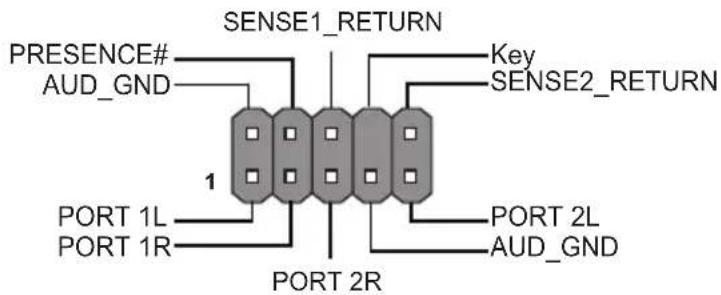
| 4. F_AUDIO Front panel audio header | |
| 5. BT CMOS Battery | |
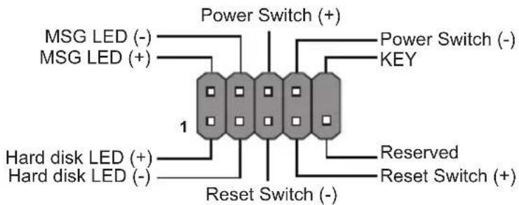
| 6. F_PANEL Front panel switch/LED header | |
| 7. M.2_SSD Support type 2242/2280 PCIex1 Gen3/ SATA SSD (Key M) | |
| 8. DC_IN1 DC Power Input | |
| 9. CLR_CMOS Clear CMOS jumper | |
| 10. CPU_FAN 4-pin CPU cooling fan connector | |
| 11. DIMM 288-pin DDR5 Module Slot | |
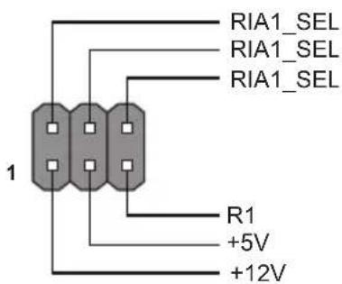
| 12. RI1_SEL COM Port RI pin select jumper | |
| 13. COM1~4 Onboard serial port header | |
| 14. F_USB Front panel USB 2.0 header | |
| 15. GPIO GPIO header | |
| 16. SATA1 | Serial ATA 6Gb/s connector |
| 17. M.2_WWAN | Support type 3052 PCIex1/USB2, USB3 Gen2x1 (Key B)*3042 (optional) |
| 18. BKLT_PWR | LCD panel back light power select jumper |
| 19. AC_PWR ATX/AT mode select jumper | |
| 20. DISP_BRT | Display brightness header |
| 21. SATA_PWR | SATA power connector |
| 22. LCD_PWR | LCD panel power select jumper |
Hader Pin Definition and Jumper Settings
F_PANEL (2.0mm)
F_AUDIO (2.0mm)
F_USB (2.54mm)

GPIO (2.0mm)

RI1_SEL
* For COM1 only
COM1\~COM4 (2.0mm)

CLR_CMOS Jumper

1-2: NORMAL

2-3: CLEAR CMOS
Before clearing the CMOS, make sure to turn off the system.
BLKT_PWR
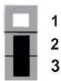
12V (default)

19V
AC_PWR
DC_IN2
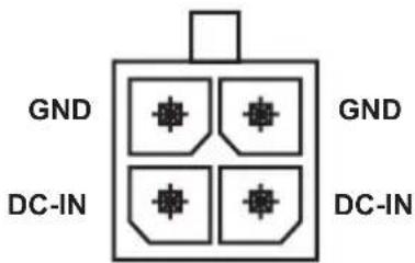

ATX Mode (default)
2

AT Mode 2
LCD_PWR
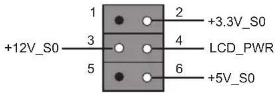
SATA

LCD_SEL

Resolution 1024 x 768 (Default)


Resolution 1600 x 900 Resolution 1680 x 1050
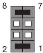
Resolution 1280 x 1024

Resolution 1366 x 768

Resolution 1920 x 1080
I/O Ports

flowchart
graph TD
    A["1"] --> B["Server Interface"]
    C["2"] --> B
    D["3"] --> E["Server Interface"]
    F["4"] --> E
    B --> G["Server Interface"]
    E --> H["Server Interface"]
1, 2 HDMI ^TM Ports
You can connect the display device to the HDMI ^TM port.
3. USB 3.2 Gen2x1 Ports
Use the USB 3.2 Gen2x1 ports to connect USB 3.2 Gen2x1 devices.
4. LAN Ports
Connect an RJ-45 jacks to the LAN port to connect your computer to the Network.
| LAN LED Status | Description | |
| Activity LED | OFF No data | |
| Yellow blinking Active | ||
| Link LED | OFF Link (10 Mbps) | |
| Green Link (100/1000 Mbps) | ||
| Orange Link (2500 Mbps) | ||

LAN Port
Hardware Installation Guide
Installation Steps
Step 1. Installation of Memory Modules:
Firmly press the DIMM down un il it seats correctly. Make sure the slot latches are levered upwards and latch on the edge of the DIMM.

natural_image
Pure technical line drawing of a mechanical component with no text or symbolsStep 2. Connecting Cables and Power Connectors:
a. Connect the SATA hard drive to its SATA cable
b. Connect SATA power connector to the SATA device

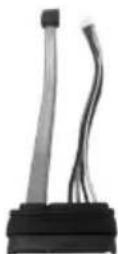
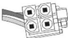
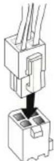
c. The 4 pin power cord is fully snapped in with the power connector at the board

Using BIOS
The BIOS (Basic Input and Output System) Setup Utility displays the system's configuration status and provides you options to set system parameters. When you power on the system, BIOS enters the Power-On Self Test (POST) routines, please press or F2 to enter setup. When powering on for the first time, the POST screen may show a "CMOS Settings Wrong" message. Please enter BIOS and choose "Load Default Settings" to reset the default CMOS values. (Changes to system hardware such as different CPU, memories, etc. may also trigger this message.)

The sequence of installation may differ depending on the type of case and devices used.
硬件安装指南
安装步骤
1. 安装记忆体模组:
natural_image
Pure technical line drawing of a mechanical component with no text or symbols2. 连接电源线与电源接头:
natural_image
Pure technical line drawing of a mechanical component or assembly (no text or symbols)natural_image
Pure technical line drawing of a mechanical component or assembly (no text or symbols)natural_image
Pure technical line drawing of a mechanical component with no text or symbolsnatural_image
Pure technical line drawing of a mechanical component or bracket (no text or symbols)About the Setup Utility
The computer uses the latest “American Megatrends Inc.” BIOS with support for Windows Plug and Play. The CMOS chip on the motherboard contains the ROM setup instructions for configuring the motherboard BIOS.
The BIOS (Basic Input and Output System) Setup Utility displays the system's configuration status and provides you with options to set system parameters. The parameters are stored in battery-backed-up CMOS RAM that saves this information when the power is turned off. When the system is turned back on, the system is configured with the values you stored in CMOS.
The BIOS Setup Utility enables you to configure:
• Hard drives, diskette drives and peripherals
• Video display type and display options
- Password protection from unauthorized use
• Power Management features
The settings made in the Setup Utility affect how the computer performs. Before using the Setup Utility, ensure that you understand the Setup Utility options.
This chapter provides explanations for Setup Utility options.
The Standard Configuration
A standard configuration has already been set in the Setup Utility. However, we recommend that you read this chapter in case you need to make any changes in the future.
This Setup Utility should be used:
- when changing the system configuration
- when a configuration error is detected and you are prompted to make changes to the Setup Utility
- when making changes to the Power Management configuration
- when changing the password or making other changes to the Security Setup
Entering the Setup Utility
When you power on the system, BIOS enters the Power-On Self Test (POST) routines. POST is a series of built-in diagnostics performed by the BIOS. After the POST routines are completed, the following message appears:
Press DEL to enter SETUP
Using BIOS
When you start the Setup Utility, the main menu appears. The main menu of the Setup Utility displays a list of the options that are available. A highlight indicates which option is currently selected. Use the cursor arrow keys to move the highlight to other options. When an option is highlighted, execute the option by pressing
Some options lead to pop-up dialog boxes that prompt you to verify that you wish to execute that option. Other options lead to dialog boxes that prompt you for information.
Some options (marked with an icon) lead to submenus that enable you to change the values for the option. Use the cursor arrow keys to scroll through the items in the submenu.
In this manual, default values are enclosed in parenthesis. Submenu items are denoted by an icon.

The default BIOS setting for this motherboard apply for most conditions with optimum performance. We do not suggest users change the default values in the BIOS setup and take no responsibility to any damage caused by changing the BIOS settings.
BIOS Navigation Keys
The BIOS navigation keys are listed below:
| KEY FUNCTION | |
| ESC Exits the current menu | |
| ↑↓→← | Scrolls through the items on a menu |
| +/- Change Opt. | |
| Enter Select | |
| F1 General Help | |
| F2 Previous Value | |
| F3 Optimized Defaults | |
| F4 Save & Exit | |

- For the purpose of better product maintenance, the manufacture reserves the right to change the BIOS items presented in this manual. The BIOS setup screens shown in this chapter are for reference only and may differ from the actual BIOS. Please visit the manufacture's website for updated manual.
- In this Gui BIOS, you can operate by mouse or keyboard. Click: select item; Double click: enter; Right click: exit.
Default
Select the default icon and press
Advanced
Select the advanced icon and press
Exit
Select the exit icon and press
Main Menu
This menu shows the information of BIOS and enables you to set the system language, date and time.
| Main | Advanced | Chipset | Tweak | Security | Boot | Exit |
| BIOS InformationSystem Language [English]System Time [02:18:06]BIOS Version 24.02.26 | Choose the system default languageDate | |||||
| →←: Select Screen↑↓: Select ItemEnter: Select+/-: Change Opt.F1: General HelpF2: Previous ValuesF3: Optimized DefaultsF4: Save & ExitESC: Exit | ||||||
| Version 2.22.1287 Copyright (C) 2024 AMI | ||||||
System Language (English)
This item is used to set system language.
System Date & Time
The Date and Time items show the current date and time on the computer. If you are running a Windows OS, these items are automatically updated whenever you make changes to the Windows Date and Time Properties utility.
Advanced Menu
The Advanced menu items allow you to change the settings for the CPU and other system.
| Main Advanced Chipset Tweak Security Boot Exit | ||||||
| LAN ConfigurationPC Health StatusPower Management SetupACPI SettingsCPU ConfigurationSATA ConfigurationUSB ConfigurationSuper IO ConfigurationTrusted Computing | LAN Configuration Parameters | |||||
| →←: Select Screen↑↓: Select ItemEnter: Select+/-: Change Opt.F1: General HelpF2: Previous ValuesF3: Optimized DefaultsF4: Save & ExitESC: Exit | ||||||
| Version 2.22.1287 Copyright (C) 2024 AMI | ||||||
» LAN Configuration
The item in the menu shows the LAN-related information that the BIOS automatically detects.
| Aptio Setup - AMI Advanced | |
| LAN ConfigurationOnboard LAN 1 Controller [Enabled]Onboard LAN 2 Controller [Enabled] | Enabled/Disabled Onboard LAN 1 Controller |
| →←: Select Screen↑↓: Select ItemEnter : Select+/-: Change Opt.F1 : General HelpF2 : Previous ValuesF3 : Optimized DefaultsF4 : Save & ExitESC : Exit | |
| Version 2.22.1287 Copyright (C) 2024 AMI | |
Onboard LAN 1 Controller (Enabled)
Use this item to enable or disable Onboard LAN1 controller.
Onboard LAN 2 Controller (Enabled)
Use this item to enable or disable Onboard LAN2 controller.
Press
» PC Health Status
On motherboards support hardware monitoring, this item lets you monitor the parameters for critical voltages, temperatures and fan speeds.
| Aptio Setup - AMI | |
| Advanced | |
| PC Health Status | |
| Smart Fan Function | |
| CPU Temperature (DTS) 37System Temperature 31°C | |
| CPU Fan Speed 3110 RPMCore Voltage 0.748VDIMM Voltage 1.155V+12V 12.144V+5VSB 4.818V+VCC 5.192VTCC Activation Temperature (DTS) 105 | →←: Select Screen↓↓: Select ItemEnter: Select+/-: Change Opt.F1: General HelpF2: Previous ValuesF3: Optimized DefaultsF4: Save & ExitESC: Exit |
| Version 2.22.1287 Copyright (C) 2024 AMI | |
» Smart Fan Function
Scroll to this item and press
| Aptio Setup - AMI Advanced | |
| Smart Fan Select CPU | Smart Fan Select |
| Smart Fan Mode [Normal] | |
| Smart Fan start PWM value 180 | |
| Smart Fan start PWM TEMP (DTS) 70 | |
| DeltaT 3 | |
| Smart Fan Slope PWM value 10 | |
| Fan Full Speed Offset (DTS) 77 | |
| →←: Select Screen↑↓: Select ItemEnter: Select+/-: Change Opt.F1: General HelpF2: Previous ValuesF3: Optimized DefaultsF4: Save & ExitESC: Exit | |
| Version 2.22.1287 Copyright (C) 2024 AMI | |
Smart Fan Select (CPU)
This item allows you to change and configure Smart Fans on M/B. ex. CPU Fan, System Fan.
Smart Fan Mode (Normal)
This item allows you to select the fan mode (Normal, Quiet, Silent, or Manual) for a better operation environment. If you choose Normal mode, the fan speed will be auto adjusted depending on the CPU temperature. If you choose Quite mode, the fan speed will be auto minimized for quiet environment. If you choose Silent mode, the fan speed will be auto restricted to make system more quietly. If you choose Manual mode, the fan speed will be adjust depending on users' parameters.
Smart Fan start PWM value (180)
This item is used to set the start PWM value of the smart fan.
Smart Fan start PWM TEMP (DTS) (70)
This item is used to set the start temperature of the smart fan.
DeltaT (3)
This item specifies the range that controls CPU temperature and keeps it from going so high or so low when smart fan works.
Smart Fan Slope PWM value (10)
This item is used to set the Slope Select PWM of the smart fan.
Fan Full Speed Offset (DTS) (77)
This item is used to set the fan full speed offset value.
Press
System Component Characteristics
These items display the monitoring of the overall inboard hardware health events, such as CPU & DIMM voltage, CPU & System fan speed...etc.
- CPU Temperature
- System Temperature
- CPU Fan Speed
- System Fan Speed
- Core Voltage
- DIMM Voltage
• +12V
+5VSB
• +VCC
TCC Activation Temperature (DTS) (105)
This item is used to set the value from the factory TCC Activation Temperature.
Press
» Power Management Setup
This page sets up some parameters for system power management operation.
| Aptio Setup - AMI Advanced | |
| Power Management SetupResume By PME [Disabled]Resume By USB [Disabled]Resume By RTC Alarm [Disabled]EUP Function [Enabled]Power LED Type [Dual Color LED]Restore AC Power Loss [Power off]PSU extra Load [Disabled] | About Resume by PCE-E/LAN/Ring PME |
| →←: Select Screen↑↓: Select ItemEnter: Select+/-: Change Opt.F1: General HelpF2: Previous ValuesF3: Optimized DefaultsF4: Save & ExitESC: Exit | |
| Version 2.22.1287 Copyright (C) 2024 AMI | |
Resume By PME (Disabled)
The system can be turned off with a software command. If you enable this item, the system can automatically resume if there is an incoming call on the PCI/PCI-E Modem or PCI/PCI-E LAN card. You must use an ATX power supply in order to use this feature. Use this item to do wake-up action if inserting the PCI/PCI-E card.
Resume By USB (Disabled)
This item allows you to enable or disable the USB device wakeup function from S3 mode.
Resume By RTC Alarm (Disabled)
The system can be turned off with a software command. If you enable this item, the system can automatically resume at a fixed time based on the system's RTC (realtime clock). Use the items below this one to set the date and time of the wake-up alarm. You must use an ATX power supply in order to use this feature.
EUP Function (Enabled)
This item allows user to enable or disable EUP support.
Power LED Type (Dual Color LED)
This item shows the type of the Power LED.
Restore AC Power Loss (Power off)
This item allows you to control the system's startup behavior when the power is restored.
PSU extra Load (Disabled)
This item enables or disables dummy load. When the power supply is at low load, a self-protection will activate causing it to shutdown or fail. If this occurs, please set to Enabled.
Press
» ACPI Settings
The item in the menu shows the highest ACPI sleep state when the system enters suspend.
| Advanced\Aptio Setup - AMI | |
| ACPI SettingsACPI Sleep State [S3 (Suspend to RAM)] | Select the highest ACPI sleep state the system will enter when the SUSPEND button is pressed. |
| →←: Select Screen↑↓: Select ItemEnter : Select+/- : Change Opt.F1 : General HelpF2 : Previous ValuesF3 : Optimized DefaultsF4 : Save & ExitESC : Exit | |
| Version 2.22.1287 Copyright (C) 2024 AMI | |
ACPI Sleep State [S3(Suspend to RAM)]
This item allows user to enter the ACPI S3 (Suspend to RAM) Sleep State (default).
Press
» CPU Configuration
The item in the menu shows the CPU.
| Aptio Setup - AMI | |
| Advanced | |
| CPU ConfigurationIntel (R) N200Processor Speed 1000 MHzID 0xB06E0Microcode Revision 15VMX SupportedSMX/TXT Not SupportedLimit CPUID Maximum [Disabled]Intel (VMX) Virtualization Technology [Enabled]Package C State Limit [C10]Enhanced Halt (C1E) [Enabled]Intel(R) Speed Shift Technology [Enabled] | Disable for Windows XP→←: Select Screen↑↓: Select ItemEnter: Select+/-: Change Opt.F1: General HelpF2: Previous ValuesF3: Optimized DefaultsF4: Save & ExitESC: Exit |
| Version 2.22.1287 Copyright (C) 2024 AMI | |
Intel (R) N200
This is display-only field and displays the information of the CPU installed in your computer.
Processor Speed (1000 MHz)
This item shows the processor speed.
ID (0xB06E0)
This item shows the processor ID.
Microcode Revision (15)
This item shows the Microcode Revision.
VMX (Supported)
This item shows the computer supports the VMX or not.
SMX/TXT (Not Supported)
This item shows the computer supports the SMX/TXT or not.
Use this item to enable or disable the maximum CPUID value limit, you can enable this item to prevent the system from "ebooting" when trying to install Windows NT 4.0.
Intel (VMX) Virtualization Technology (Enabled)
When disabled, a VMM cannot utilize the additional hardware capabilities provided by Vandor Pool Technology.
Package C State Limit (C10)
Use this item to set the Package C State limit.
Enhanced Halt (C1E) (Enabled)
Use this item to enable or disable the Enhanced C1 state.
Intel(R) Speed Shift Technology (Enabled)
Use this item to enable the CPU energy-saving function when the system is not running.
Press
» SATA Configuration
Use this item to show the mode of serial SATA configuration options.
| Aptio Setup - AMI Advanced | |
| SATA Configuration | Determines how SATA controller(s) operate. |
| SATA Mode Selection [AHCI] | |
| SATA Port1Not Present | |
| M2Not Present | →←: Select Screen↑↓: Select ItemEnter: Select+/-: Change Opt.F1: General HelpF2: Previous ValuesF3: Optimized DefaultsF4: Save & ExitESC: Exit |
| NVMe Configuration | |
| Version 2.22.1287 Copyright (C) 2024 AMI | |
SATA Mode Selection (AHCI)
Use this item to select SATA mode.
SATA Port 1 (Not Present)
This item shows the SATA Port 1 Device.
M2 (Not Present)
This item shows the M2 Device.
▶ NVMe Configuration
NVMe Device Options Settings.
| Aptio Setup - AMI Advanced | |
| NVMe controller and Drive informationBus: Dev: 0 Func:0 PLEXTOR PX-256M9PeGN NVMe Size 256.0GB | |
| →← : Select Screen1↓ : Select ItemEnter : Select+/- : Change Opt.F1 : General HelpF2 : Previous ValuesF3 : Optimized DefaultsF4 : Save & ExitESC : Exit | |
| Version 2.22.1287 Copyright (C) 2024 AMI | |
NVMe controller and Drive information
This item shows NVMe device information (Model Name, Size).
Press
Press
» USB Configuration
Use this item to show the information of USB configuration.
| Aptio Setup - AMI Advanced | |
| USB ConfigurationAll USB Devices Enabled | USB Support Parameters |
| →←: Select Screen↑↓: Select ItemEnter : Select+/- : Change Opt.F1 : General HelpF2 : Previous ValuesF3 : Optimized DefaultsF4 : Save & ExitESC : Exit | |
| Version 2.22.1287 Copyright (C) 2024 AMI | |
All USB Devices (Enabled)
Use this item to enable or disable all USB devices.
Press
» Super IO Configuration
Use this item to show the information of Super IO configuration.
| Aptio Setup - AMI | ||
| Advanced | ||
| Super IO Configuration | Set Parameters of Serial Port 1 (COMA) | |
| Super IO Chip | IT8786 | |
| Serial Port 1 Configuration COM1 Mode | [RS232 Mode] | |
| COM1 Speed | [High] | |
| Serial Port 2 Configuration | →←: Select Screen↑↓: Select ItemEnter : Select+/-: Change Opt.F1 : General HelpF2 : Previous ValuesF3 : Optimized DefaultsF4 : Save & ExitESC : Exit | |
| Serial Port 3 Configuration | ||
| Serial Port 4 Configuration | ||
| Version 2.22.1287 Copyright (C) 2024 AMI | ||
Super IO Chip (IT8786)
This item shows the information of the super IO chip.
» Serial Port 1 Configuration
Scroll to this item and press
| Aptio Setup - AMI | ||
| Advanced | ||
| Serial Port 1 Configuration | Enable or Disable Serial Port (COM) | |
| Serial Port | EnabledIO=3F8h; IRQ=4; Device Settings | |
| Change Settings | [Auto] | →←: Select Screen↑↓: Select ItemEnter: Select+/-: Change Opt.F1: General HelpF2: Previous ValuesF3: Optimized DefaultsF4: Save & ExitESC: Exit |
| Version 2.22.1287 Copyright (C) 2024 AMI | ||
Serial Port (Enabled)
This item allows you to enable or disable serial port.
Device Settings (IO=3F8h; IRQ=4)
This item shows the information of the device settings.
Change Settings (Auto)
Use this item to change device settings.
Press
» Serial Port 2 Configuration
Scroll to this item and press
| Advanced Aptio Setup - AMI | ||
| Serial Port 2 Configuration Serial Port Enabled IO=2F8h; IRQ=3; Device Settings Change Settings [Auto] | Enable or Disable Serial Port (COM) | |
| →←: Select Screen ↑↓: Select Item Enter: Select +/-: Change Opt. F1: General Help F2: Previous Values F3: Optimized Defaults F4: Save & Exit ESC: Exit | ||
| Version 2.22.1287 Copyright (C) 2024 AMI | ||
Serial Port (Enabled)
This item allows you to enable or disable serial port.
Device Settings (IO=2F8h; IRQ=3)
This item shows the information of the device settings.
Change Settings (Auto)
Use this item to change device settings.
Press
» Serial Port 3 Configuration
Scroll to this item and press
| Advanced Aptio Setup - AMI | ||
| Serial Port 3 Configuration Serial Port Enabled IO=3E8h; IRQ=7; Change Settings [Auto] | Enable or Disable Serial Port (COM) Device Settings | |
| →←: Select Screen ↑↓: Select Item Enter: Select +/-: Change Opt. F1: General Help F2: Previous Values F3: Optimized Defaults F4: Save & Exit ESC: Exit | ||
| Version 2.22.1287 Copyright (C) 2024 AMI | ||
Serial Port (Enabled)
This item allows you to enable or disable serial port.
Device Settings (IO=3E8h; IRQ=7)
This item shows the information of the device settings.
Change Settings (Auto)
Use this item to change device settings.
Press
» Serial Port 4 Configuration
Scroll to this item and press
| Advanced Aptio Setup - AMI | ||
| Serial Port 4 Configuration Serial Port Enabled IO=2E8h; IRQ=7; Device Settings Change Settings [Auto] | Enable or Disable Serial Port (COM) | |
| →←: Select Screen ↑↓: Select Item Enter: Select +/-: Change Opt. F1: General Help F2: Previous Values F3: Optimized Defaults F4: Save & Exit ESC: Exit | ||
| Version 2.22.1287 Copyright (C) 2024 AMI | ||
Serial Port (Enabled)
This item allows you to enable or disable serial port.
Device Settings (IO=2E8h; IRQ=7)
This item shows the information of the device settings.
Change Settings (Auto)
Use this item to change device settings.
Press
» Trusted Computing
Use this item to show the information of trusted computing configuration.
| Aptio Setup - AMI | |
| Advanced | |
| TPM 2.0 Device FoundFirmware Version : 600.18Vendor : INTCTPM Support [Enabled]Active PCR banks SHA256Available PCR banks SHA256, SHA384, SM3SHA256 PCR Bank [Enabled]SHA384 PCR Bank [Disabled]SM3_256 PCR Bank [Disabled]Pending operation [None]Platform Hierarchy [Enabled]Storage Hierarchy [Enabled]Endorsement Hierarchy [Enabled]Physical Presence Spec Version [1.3]TPM 2.0 InterfaceType [CRB] | Enables or Disables BIOS support for security device, O.S. will not show Security Device.TCG EFI protocol and INT1A interface will not be available. |
| ←←: Select Screen↑↓: Select ItemEnter: Select+/-: Change Opt.F1: General HelpF2: Previous ValuesF3: Optimized DefaultsF4: Save & ExitESC: Exit | |
| Version 2.22.1287 Copyright (C) 2024 AMI | |
TPM Support (Enabled)
Use this item to enable or disable the TPM support. O.S. will not show TPM. Reset of platform is required.
Active PCR banks (SHA256)
Use this item to show the Active PCR banks.
Available PCR banks (SHA256, SHA384, SM3)
Use this item to show the Available PCR banks.
SHA256 PCR Bank (Enabled)
Use this item to enable or disable the SHA256 PCR bank.
SHA384 PCR Bank (Disabled)
Use this item to enable or disable the SHA384 PCR bank.
SM3\_256 PCR Bank (Disabled)
Use this item to enable or disable the SM3_256 PCR bank.
Pending operation (None)
Schedule an Operation for the Security Device. NOTE: Your Computer will reboot during restart in order to change State of Security Device.
Platform Hierarchy (Enabled)
Use this item to enable or disable the platform hierarchy.
Storage Hierarchy (Enabled)
Use this item to enable or disable the storage hierarchy.
Endorsement Hierarchy (Enabled)
Use this item to enable or disable the Endorsement hierarchy.
Physical Presence Spec Version (1.3)
Use this item to show the Physical Presence Spec Version.
TPM 2.0 Interface Type (CRB)
Use this item to select the communication interface to TPM 20 device.
Press
Chipset Menu
The chipset menu items allow you to change the settings for the North Bridge chipset, South Bridge chipset and other system.

» System Agent Configuration
Scroll to this item and press
| Chipset Aptio Setup - AMI | |
| System Agent Configuration IGD Memory [64M] DVMT/FIXED Memory [256M] | Select DVMT 5.0 Pre-Allocated (Fixed) Graphics Memory size used by the Internal Graphics Device. |
| →←: Select Screen ↑↓: Select Item Enter: Select +/-: Change Opt. F1: General Help F2: Previous Values F3: Optimized Defaults F4: Save & Exit ESC: Exit | |
| Version 2.22.1287 Copyright (C) 2024 AMI | |
IGD Memory (64M)
This item shows the information of the IGD (Internal Graphics Device) memory.
DVMT/FIXED Memory (256M)
When set to Fixed Mode, the graphics driver will reserve a fixed position of the system memory as graphics memory, according to system and graphics requirement.
Press
» PCH Configuration
Scroll to this item and press
| Chipset Aptio Setup - AMI | |
| PCH ConfigurationAudio ConfigurationHD Audio [ | Control Detection of the HD-Audio device. Disabled = HDA will be unconditionally disabled Enabled = HDA will be unconditionally enabled. Enabled] |
| →←: Select Screen↑↓: Select ItemEnter : Select+/-: Change Opt.F1 : General HelpF2 : Previous ValuesF3 : Optimized DefaultsF4 : Save & ExitESC : Exit | |
| Version 2.22.1287 Copyright (C) 2024 AMI | |
HD Audio (Enabled)
This item enables or disables Azalia HD audio.
Press
» ME Configuration
Scroll to this item and press
| Chipset\Aptio Setup - AMI | |
| Management Engine Technology ConfigurationME Control [Enabled]ME FW Version 16.50.10.1351 | when Disabled ME will be put into ME Temporarily Disabled Mode. |
| →←: Select Screen↑↓: Select ItemEnter: Select+/-: Change Opt.F1: General HelpF2: Previous ValuesF3: Optimized DefaultsF4: Save & ExitESC: Exit | |
| Version 2.22.1287 Copyright (C) 2024 AMI | |
ME Control (Enabled)
Use this item to enable or disable the ME Firmware.
ME FW Version (16.50.10.1351)
This item shows the ME FW version.
Tweak Menu
This page displays your system's processor model, clock speed, and memory clock speed. The information depends on the type of processor installed in your system.
| Main Advanced Chipset Tweak Security Boot Exit | ||||||
| TweakIntel(R) N200 Processor Speed 1000 MHz Memory Frequency 4800 MHz Total Memory 16384 MB | ||||||
| →←: Select Screen↑↓: Select ItemEnter: Select+/-: Change Opt.F1: General HelpF2: Previous ValuesF3: Optimized DefaultsF4: Save & ExitESC: Exit | ||||||
| Version 2.22.1287 Copyright (C) 2024 AMI | ||||||
Inter(R) N200
This is display-only field and displays the information of the CPU installed in your computer.
Processor Speed (1000 MHz)
This item shows the processor speed.
Memory Frequency (4800MHz)
This item shows the information of the memory frequency.
This item shows the information of the total memory.
Security Menu
This page enables you to set setup administrator password and user password.
| Main Advanced Chipset Tweak Security Boot Exit | |||||
| Administrator PasswordAdministrator Password Status Not InstallUser Password Status Not InstallSystem Mode state SetupSecure Boot state Not ActiveSecure Boot [Enabled]Secure Boot Mode [Standard] | Set Administrator Password→←: Select Screen↑↓: Select ItemEnter: Select+/-: Change Opt.F1: General HelpF2: Previous ValuesF3: Optimized DefaultsF4: Save & ExitESC: Exit | ||||
| Version 2.22.1287 Copyright (C) 2024 AMI | |||||
Administrator Password Status (Not Install)
This item shows administrator password installed or not.
User Password Status (Not Install)
This item shows user password installed or not.
System Mode state (Setup)
This item shows system mode setup or not.
Secure Boot state (Not Active)
This item allows you to enable or disable the secure boot state.
Secure Boot (Enabled)
This item is used to control the secure boot flow, it is possible only if system runs in User Mode.
Secure Boot Mode (Standard)
This item is used to select the secure boot mode.
Boot Menu
This page enables you to set the keyboard NumLock state.
| Aptio Setup - AMI | ||||||
| Main | Advanced | Chipset | Tweak | Security | Boot | Exit |
| Boot ConfigurationLaunch PXE OpROM [Disabled]Launch Storage OpROM [Enabled]Fast Boot [Disabled]Bootup NumLock State [On]Quiet Boot [Enabled]Update System BIOS [Disabled]Boot mode select [UEFI]FIXED BOOT ORDER PrioritiesBoot Option #1 [Hard Disk]Boot Option #2 [NVME]Boot Option #3 [CD/DVD]Boot Option #4 [USB Floppy]Boot Option #5 [USB CD/DVD]Boot Option #6 [USB Hard Disk]Boot Option #7 [USB Key : UEFI : ADAT...]Boot Option #8 [Network]Boot Option #9 [Other Device]UEFI USB Key Drive BBS Priorities | Enable or disable Boot Option for Legacy Network Devices.→←: Select Screen↑↓: Select ItemEnter : Select+/- : Change Opt.F1 : General HelpF2 : Previous ValuesF3 : Optimized DefaultsF4 : Save & ExitESC : Exit | |||||
Launch PXE OpROM (Disabled)
The item enables or disables launch PXE Option ROM.
Launch Storage OpROM (Enabled)
Use this item to enable or disable the Storage OpROM.
This item enables or disables boot with initialization of a minimal set of device required to launch active boot option. Has no effect for BBS boot options.
Bootup NumLock State (On)
This item enables you to select NumLock state.
Quiet Boot (Enabled)
This item enables or disables quiet boot.
Update System BIOS (Disabled)
This item enables or disables Update System BIOS.
Boot mode select (UEFI)
Use this item to select boot mode.
These items show the boot priorities.
UEFI USB Key Drive BBS Priorities
This item enables you to specify the sequence of loading the operating system from the installing USB Key drive. Press
Exit Menu
This page enables you to exit system setup after saving or without saving the changes.
| Aptio Setup - AMI | |
| Main Advanced Chipset Tweak Security Boot Exit | |
| Save Changes and ExitDiscard Changes and ExitSave Changes and ResetDiscard Changes and ResetSave OptionsSave ChangesDiscard ChangesRestore DefaultsSave as User DefaultsRestore User DefaultsBoot OverrideUFFI: ADATA USB Flash Drive 1100, Partition 1 (ADATA USB... | Exit system setup after saving the changes.→←: Select Screen↑↓: Select ItemEnter: Select+/-: Change Opt.F1: General HelpF2: Previous ValuesF3: Optimized DefaultsF4: Save & ExitESC: Exit |
| Version 2.22.1287 Copyright (C) 2024 AMI | |
Save Changes and Exit
This item enables you to exit the system setup after saving the changes.
Discard Changes and Exit
This item enables you to exit system setup without saving any changes.
Save Changes and Reset
This item enables you to reset system setup after saving the changes.
Discard Changes and Reset
This item enables you to reset system setup without saving any changes.
Save Options
This item enables you to save the options that you have made.
Save Changes
This item enables you to save the changes that you have made.
Discard Changes
This item enables you to discard any changes that you have made.
Restore Defaults
This item enables you to restore defaults to all the setup options.
Save as User Defaults
This item enables you to save the changes that you have made as user defaults.
This item enables you to restore the user defaults.
Boot Override
Use this item to select the boot device.
Updating the BIOS
You can download and install updated BIOS for this motherboard from the manufacturer's Website. New BIOS provides support for new peripherals, improvements in performance, or fixes for known bugs. Install new BIOS as follows:
1 If your motherboard has a BIOS protection jumper, change the setting to allow BIOS flashing.
2 If your motherboard has an item called Firmware Write Protect in Advanced BIOS features, disable it. (Firmware Write Protect prevents BIOS from being overwritten.)
3 Prepare a bootable device or create a bootable system disk. (Refer to Windows online help for information on creating a bootable system disk.)
4 Download the Flash Utility and new BIOS file from the manufacturer's Web site. Copy these files to the bootable device.
5 Turn off your computer and insert the bootable device in your computer. (You might need to run the Setup Utility and change the boot priority items on the Advanced BIOS Features Setup page, to force your computer to boot from the bootable device first.)
6 At the fs0:> prompt, type the Flash Utility program name and the file name of the new BIOS and then press
7 When the installation is complete, remove the bootable device from the computer and restart your computer. If your motherboard has a Flash BIOS jumper, reset the jumper to protect the newly installed BIOS from being overwritten. The computer will restart automatically.
This concludes Chapter 3. Refer to the next chapter for information on the trouble shooting with the motherboard.
- Federal Communications Commission (FCC)
- Declaration of Conformity
- Preface ....i
- Brief Introduction
- Multi-language Quick Installation Guide
- Using BIOS
- Hader Pin Definition and Jumper Settings
- I/O Ports
- 1, 2 HDMI TM Ports
- USB 3.2 Gen2x1 Ports
- LAN Ports
- Hardware Installation Guide
- Installation Steps
- Step 1. Installation of Memory Modules:
- Step 2. Connecting Cables and Power Connectors:
- 硬件安装指南
- 安装步骤
- 安装记忆体模组:
- 连接电源线与电源接头:
- About the Setup Utility
- The Standard Configuration
- Entering the Setup Utility
- BIOS Navigation Keys
- Default
- Advanced
- Exit
- Main Menu
- System Language (English)
- System Date & Time
- Advanced Menu
- » LAN Configuration
- Onboard LAN 1 Controller (Enabled)
- Onboard LAN 2 Controller (Enabled)
- » PC Health Status
- » Smart Fan Function
- Smart Fan Select (CPU)
- Smart Fan Mode (Normal)
- Smart Fan start PWM value (180)
- Smart Fan start PWM TEMP (DTS) (70)
- DeltaT (3)
- Smart Fan Slope PWM value (10)
- Fan Full Speed Offset (DTS) (77)
- System Component Characteristics
- TCC Activation Temperature (DTS) (105)
- » Power Management Setup
- Resume By PME (Disabled)
- Resume By USB (Disabled)
- Resume By RTC Alarm (Disabled)
- EUP Function (Enabled)
- Power LED Type (Dual Color LED)
- Restore AC Power Loss (Power off)
- PSU extra Load (Disabled)
- » ACPI Settings
- ACPI Sleep State [S3(Suspend to RAM)]
- » CPU Configuration
- Intel (R) N200
- Processor Speed (1000 MHz)
- ID (0xB06E0)
- Microcode Revision (15)
- VMX (Supported)
- SMX/TXT (Not Supported)
- Intel (VMX) Virtualization Technology (Enabled)
- Package C State Limit (C10)
- Enhanced Halt (C1E) (Enabled)
- Intel(R) Speed Shift Technology (Enabled)
- » SATA Configuration
- SATA Mode Selection (AHCI)
- SATA Port 1 (Not Present)
- M2 (Not Present)
- ▶ NVMe Configuration
- NVMe controller and Drive information
- » USB Configuration
- All USB Devices (Enabled)
- » Super IO Configuration
- Super IO Chip (IT8786)
- » Serial Port 1 Configuration
- Serial Port (Enabled)
- Device Settings (IO=3F8h; IRQ=4)
- Change Settings (Auto)
- » Serial Port 2 Configuration
- Device Settings (IO=2F8h; IRQ=3)
- » Serial Port 3 Configuration
- Device Settings (IO=3E8h; IRQ=7)
- » Serial Port 4 Configuration
- Device Settings (IO=2E8h; IRQ=7)
- » Trusted Computing
- TPM Support (Enabled)
- Active PCR banks (SHA256)
- Available PCR banks (SHA256, SHA384, SM3)
- SHA256 PCR Bank (Enabled)
- SHA384 PCR Bank (Disabled)
- SM3\_256 PCR Bank (Disabled)
- Pending operation (None)
- Platform Hierarchy (Enabled)
- Storage Hierarchy (Enabled)
- Endorsement Hierarchy (Enabled)
- Physical Presence Spec Version (1.3)
- TPM 2.0 Interface Type (CRB)
- Chipset Menu
- » System Agent Configuration
- IGD Memory (64M)
- DVMT/FIXED Memory (256M)
- » PCH Configuration
- HD Audio (Enabled)
- » ME Configuration
- ME Control (Enabled)
- ME FW Version (16.50.10.1351)
- Tweak Menu
- Inter(R) N200
- Memory Frequency (4800MHz)
- Security Menu
- Administrator Password Status (Not Install)
- User Password Status (Not Install)
- System Mode state (Setup)
- Secure Boot state (Not Active)
- Secure Boot (Enabled)
- Secure Boot Mode (Standard)
- Boot Menu
- Launch PXE OpROM (Disabled)
- Launch Storage OpROM (Enabled)
- Bootup NumLock State (On)
- Quiet Boot (Enabled)
- Update System BIOS (Disabled)
- Boot mode select (UEFI)
- UEFI USB Key Drive BBS Priorities
- Exit Menu
- Save Changes and Exit
- Discard Changes and Exit
- Save Changes and Reset
- Discard Changes and Reset
- Save Options
- Save Changes
- Discard Changes
- Restore Defaults
- Save as User Defaults
- Boot Override
- Updating the BIOS
Brand : ECS
Model : ADLN-IE1
Category : Motherboard