
i86V-01 - Intercom FlyingVoice - Free user manual and instructions
Find the device manual for free i86V-01 FlyingVoice in PDF.


| Product Type | SIP Audio/Video Intercom |
| Model | i86V-01 |
| Dust/Water Protection | IP65 |
| Power Supply | PoE (802.3af) or 12V DC/1A |
| Network Interface | 10/100 Mbps Ethernet (WAN) with PoE |
| Camera | 2 MP, max resolution 1920x1080 |
| Audio | Built-in speaker |
| Key Buttons | 3 physical keys (Left, Middle, Right) |
| Input Port | 1x short circuit input (for switches, sensors) |
| Output Port | 1x relay (NC/COM/NO, max DC30V/1A or AC125V/0.3A) |
| TF Card Slot | Yes (for storage) |
| Wireless | WiFi (for configuration only) |
| Installation | Standard type-86 box (86x86 mm) |
| Operating Temperature | 0°C to 50°C (estimated) |
| Weight | Approximately 200 g |
| Package Contents | i86V-01, connector, screwdriver, screws, quick guide |
| Compliance | FCC Part 15, CE |
| Manufacturer | Flyingvoice Network Technology Co., Ltd. |
Frequently Asked Questions - i86V-01 FlyingVoice
User questions about i86V-01 FlyingVoice
0 question about this device. Answer the ones you know or ask your own.
Ask a new question about this device
Download the instructions for your Intercom in PDF format for free! Find your manual i86V-01 - FlyingVoice and take your electronic device back in hand. On this page are published all the documents necessary for the use of your device. i86V-01 by FlyingVoice.
USER MANUAL i86V-01 FlyingVoice
natural_image
Close-up of a black electronic device with a circular button and dotted grid pattern (no visible text or symbols)
natural_image
Front view of a black electronic device with a circular button and two phone icons (① and ②) on the side, no readable text or symbols.i86V Series User's Guide
Version: 0.1
Date: Jul. 2023
Copyright
Copyright © 2020 Flyingvoice Network Technology CO., LTD.
Copyright © 2020 Flyingvoice Network Technology CO., LTD. All rights reserved. No parts of this publication may be reproduced or transmitted in any form or by any means, electronic or mechanical, photocopying, recording, or otherwise, for any purpose, without the express written permission of Flyingvoice Network Technology CO., LTD. Under the law, reproducing includes translating into another language or format.
When this publication is made available on media, Flyingvoice Network Technology CO., LTD. gives its consent to downloading and printing copies of the content provided in this file only for private use but not for redistribution. No parts of this publication may be subject to alteration, modification or commercial use. Flyingvoice Network Technology CO., LTD. will not be liable for any damages arising from use of an illegally modified or altered publication.
Trademark
Flyingvoice®, the logo and the name and marks are trademark of Flyingvoice Network Technology CO., LTD, which are registered legally in China, the United States, EU (European Union) and other countries.
All other trademarks belong to their respective owners. Without Flyingvoice's express written permission, the recipient shall not reproduce or transmit any portion thereof in any form or by any means, with any purpose other than personal use.
Warranty
1. Warranty
THE SPECIFICATIONS AND INFORMATION REGARDING THE PRODUCTS IN THIS GUIDE ARE SUBJECT TO CHANGE WITHOUT NOTICE. ALL STATEMENTS, INFORMATION, AND RECOMMENDATIONS IN THIS GUIDE ARE BELIEVED TO BE ACCURATE AND PRESENTED WITHOUT WARRANTY OF ANY KIND, EXPRESS OR IMPLIED. USERS MUST TAKE FULL RESPONSIBILITY FOR THEIR APPLICATION OF PRODUCTS.
2. Disclaimer
FLYINGVOICE NETWORK TECHNOLOGY CO., LTD. MAKES NO WARRANTY OF ANY KIND WITH REGARD TO THIS GUIDE, INCLUDING, BUT NOT LIMITED TO, THE IMPLIED WARRANTIES OF MERCHANTABILITY AND FITNESS FOR A
PARTICULAR PURPOSE. FLYINGVOICE Network Technology CO., LTD. shall not be liable for errors contained herein nor for incidental or consequential damages in connection with the furnishing, performance, or use of this guide.
3. Limitation of Liability
Flyingvoice and/or its respective suppliers are not responsible for the suitability of the information contained in this document for any reason. The information is provided “as is”, and Flyingvoice does not provide any warranty and is subject to change without notice. All risks other than risks caused by use of the information are borne by the recipient. In no event, even if Flyingvoice has been suggested the occurrence of damages that are direct, consequential, incidental, special, punitive or whatsoever (Including but not limited to loss
of business profit, business interruption or loss of business information), shall not be liable for these damages.
End User License Agreement
This End User License Agreement ("EULA") is a legal agreement between you and Flyingvoice. By installing, copying or otherwise using the Products, you: (1) agree to be bounded by the terms of this EULA, (2) you are the owner or an authorized user of the device, and (3) you represent and warrant that you have the right, authority and capacity to enter into this agreement and to abide by all its terms and conditions, just as if you had signed it. The EULA for this product is available on the Flyingvoice Support page for the product.
Patent Information
China, the United States, EU (European Union) and other countries are protecting one or more patents of accompanying products and/or patents being applied by Flyingvoice.
Technical Support
Visit www.flyingvoice.com for product documents and FAQ, or contact Flyingvoice by email at support@flyingvoice.com. We'll get you the help you need.
Declaration of Conformity
Part 15 FCC Rules
This device complies with Part 15 of the FCC Rules. Operation is subject to the following three conditions:
• This device may not cause harmful interference
- This device must accept any interference received, including interference that may cause undesired operation.
- The distance between user and products should be no less than 20cm
Note: This equipment has been tested and found to comply with the limits of a Class B digital device, pursuant to Part 15 of the FCC Rules. These limits are designed to provide reasonable protection against harmful interference in a residential installation. This equipment generates, uses and can radiate radio frequency energy, and if not installed and used in accordance with the instructions, may cause harmful interference to radio or television reception, which can be determined by turning the equipment off and on, the user is encouraged to try to correct the interference by one or more of the following measures:
-- Reorient or relocate the receiving antenna.
-- Increase the separation between the equipment and receiver.
-- Connect the equipment into an outlet on a circuit different from that to which the receiver is connected.
-- Consult the dealer or an experienced radio/TV technician for help.
Note: The manufacturer is not responsible for any radio or TV interference caused by unauthorized modifications to this equipment. Such modifications could void the user's authority to operate this equipment.
Changes or modifications not expressly approved by the party responsible for compliance could void the user's authority to operate the equipment.
CE
Manufacturer: Flyingvoice Network Technology Co., Ltd.
Address: 1801-1802, Building 1, Chongwen Park, Nanshan Zhiyuan, Nanshan District, Shenzhen, China
Hereby, Flyingvoice Network Technology Co., Ltd. declares that this device is in compliance with the essential requirements and other relevant provisions of Directive 2014/53/EU
A copy of the declaration of conformity can be obtained with this user guide; this product is not restricted in the EU.
The wireless operation frequency
WIFI: 2412MHz-2472MHz, Max EIRP Power 18.16 dBm
Safety warning and Attentions
If use adapter, adapter must be comply 2014/30/EU Directive.
Adapter Caution: Adapter shall be installed near the equipment and shall be easily accessible.
Do not store or use your product in temperatures higher than 50^ C.
RF Exposure Statement
The distance between user and products should be no less than 20cm.
GNU GPL INFORMATION
Flyingvoice phone firmware contains third-party software under the GNU General Public License (GPL). Flyingvoice uses software under the specific terms of the GPL. Please refer to the GPL for the exact terms and conditions of the license.
The original GPL license, source code of components licensed under GPL and used in Flyingvoice products can be downloaded online:
https://www.flyingvoice.com/soft_GPL.aspx
Risk Warning Statement
This risk warning statement contains a summary of external network servers that FVUI will access under its factory settings in order to obtain necessary service support. If you want to prohibit these accesses based on security considerations, you can disable them through the WEB management page.
| Number | Server Domain Name | Description | Factory Setting |
| 1 | https://prv3.flyingvoice.net:442 | Flyingvoice Provision web management configuration server | Enable |
| 2 | prv3.flyingvoice.net:3450 | Flyingvoice Provision web management stun server | Enable |
| 3 | https://prv4.flyingvoice.net | Flyingvoice Provision web management backup server | Enable |
| 4 | log3.flyingvoice.net:9005 | Flyingvoice Provision web management log server | Disable |
| 5 | http://acs3.flyingvoice.net:8080 | Flyingvoice TR069 web management server | Disable |
| 6 | acs3.flyingvoice.net:3478 | Flyingvoice TR069 web management server | Disable |
| 7 | pool.ntp.org/cn.pool.ntp.org | NTP server | Enable |
| 8 | https://rps.flyingvoice.net | Flyingvoice Provision redirect server | Enable |
Table of Contents
Chapter 1 Forewords....1
Chapter 2 Overviews....2
2.1 Appearance Introductions....2
2.2 Interface Introductions ...... 4
2.3 Package Contents....5
2.4 Documents 5
Chapter 3 Getting Started with Users ....6
3.1 Device Installations....6
3.1.1 Wiring....6
3.1.2 i86V Bottom Box Installation....7
3.1.3 Device Boot....7
3.2 Quick Settings 8
3.2.1 Get Device IP 8
3.2.2 Web Page Management 8
3.2.3 Account Registration....9
Chapter 4 Basic Functions....10
4.1 Make a Call....10
4.1.1 Number Speed Dialing....10
4.1.2 IP Direct Dialing....11
4.2 Answer a Call....11
4.3 Hang Up the Phone....11
4.4 Auto Answer....11
4.5 Function Keys Setting....12
Chapter 5 Advanced Functions ...... 14
5.1 Multicast Broadcast....14
5.2 Input Port Setting....15
5.3 Output Port Setting....16
5.4 DTMF 19
5.5 Camera Settings....21
Chapter 6 Bulk Deployment....22
6.1 FDC 22
6.1.1 Bulk Upgrade....22
6.1.2 Export Profile 24
Chapter 7 Web Page Configuration....25
7.1 Device Status 25
7.2 Restore Factory Settings ....25
7.3 Firmware Updates....26
Chapter 1 Forewords
The i86V is a SIP audio & video terminal intercom. It has a exquisite appearance, clear and high-definition voice, and provides users with high-quality communication intercom services. And its dust-proof and water-proof level meets the IP65 standard, which is applicable to indoor and outdoor to use. It integrates intelligent security, audio intercom, video surveillance and broadcasting functions to meet the needs of industry users for one key help, one key unlock, two-way intercom, real-time broadcasting, etc.
This guide is designed to help you be familiar with the functions of the i86V intercom quickly.
Firstly, please confirm with your system administrator that the network deployment related to the i86V intercom has been completed.
Secondly, you can find the Quick Start Guide in the box and read it carefully before installing and using the i86V intercom. Some of the functions described in this article need to be configured by the administrator or are limited to your i86V intercom environment previously, so please be aware that some functions may be disabled or the description is not completely consistent with the implementation operation.
The examples or pictures in this guide are for reference only.
Instruction
This user's Guide contains the following information about FlyingVoice products:
- i86V-01
- i86V-02
Chapter 2 Overviews
Before using the intercom, we recommend you to familiarize with the appearance and interface of the i86V intercom. Except for the special instructions in the guide, the other way around is similar to a normal phone. This chapter gives an overview of the i86V intercom, including the following:
- Appearance Introductions
- Interface Introductions
- Package Contents
- Documents
For further information and support, please contact your system administrator.
2.1 Appearance Introductions
The main hardware components of the i86V (including i86V-01 and i86V-02) are as follows:

flowchart
graph LR
    A["Device 1"] -->|①| B["Phone ①"]
    C["Device 2"] -->|②| D["Phone ②"]
    E["Device 3"] -->|③| F["Phone ③"]
    G["Device 4"] -->|④| H["Phone ④"]
    I["Device 5"] -->|⑤| J["Phone ⑤"]
Figure 2-1 (Front)

Figure 2-2 (Remove the cover)
The main hardware components of the i86V intercom are described as follows:
| Serial Number | Name | Instructions |
| 1 | Middle Key | Definition: Dialing Key, answering keyOne key intercom call, off hook or on hook |
| 2 | Left Key | Definition: Dialing key, answering keyOne key intercom call, off hook or on hook |
| 3 | Right Key | Definition: Door opening key or multi-function keyDoor opening, speed dial or other advanced functions can be configured |
| 4 | Camera | Surveillance camera (Default enabled) |
| 5 | Speaker | Intercom Speaker |
| 6 | Fuselage Sticker | SSID: Wireless WiFi NameSN: Product IDMAC: MAC Address |
| 7 | Reset Key(The cover needs to be removed) | Functions:1. Restore factory settings2. Turn on WiFi |
| 8 | Screw Hole | type-86 Box Screw Hole Position |
2.2 Interface Introductions
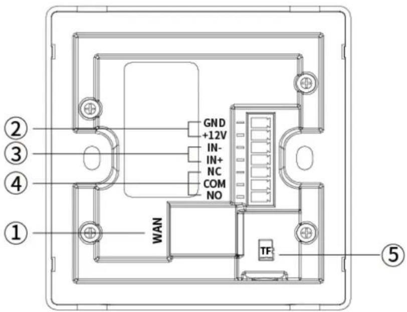
Figure 2-3 (Back)
The interface on the back of the i86V intercom is described as follows:
| 1 | WAN Interface | 10/100M Network InterfaceSupport PoE to input |
| 2 | Power Interface | 12V/1A (Input/Output) |
| 3 | Short Circuit Input Interface | Used to connect switches, infrared probes, vibration sensors and other input deviceInput+: Input Positive PoleInput-: Input Negative PoleRated voltage of input interface 12V |
| 4 | Short Circuit Output Interface | Used to control electric locks, alarms, etcNC: Connected in idle state (normally closed)COM: Contact of relay (Common)NO: Disconnected in idle state (normally open)Default NC/COM connection, rated voltage: 12V, maximum voltage: DC30V/1A, AC125V/0.3A |
| 5 | TF Card Interface | TF memory card can be inserted |
2.3 Package Contents
| Serial Number | Name | Quantity |
| 01 | i86V-01 or i86V-02 | 1 |
| 02 | Connector | 1 |
| 03 | Small Screwdriver | 1 |
| 04 | Screws | 2 |
| 05 | Quick Installation Guide | 1 |
2.4 Documents
The user's documents available for the i86V series are:
| Name | Content | Position | Language |
| Quick Installation Guide | Installation steps and basic configuration of i86V series | Package | Chinese or English |
| Flyingvoice Official Website | Chinese or English | ||
| User's Guide | Intercom introductions, basic functions and advanced functions and configuration | FlyingVoice Official Website | Chinese or English |
Chapter 3 Getting Started with Users
This chapter describes how to get started with the i86V, including the following:
● Device Installations
- Quick Settings
For further information and support, please contact your system administrator.
3.1 Device Installations
3.1.1 Wiring
- If PoE power supply is needed, plug the network cable into the WAN interface.
- If powered by 12V DC, connect the power cord and the connector and plug in the device.
- To use the access control function, please refer to the following picture:

Figure 3-1
- By default, NC-COM is in the channel state and NO-COM is in the open circuit state at the output interface. If you need to use an input interface, you can connect the device to the output interface according to your specific needs. The following is an example of door lock device wiring:
(1) Power on normally closed door lock: refer to Figure 3-1 and connect the door lock to NC and COM.
(2) Power on normally open door lock: connect the door lock to the NO-COM interface.
- To use the input interface, there are two wiring methods, which are selected according to your device conditions, as follows:
(1) For passive device (without power supply device), refer to Figure 3-1 and connect the switch.
(2) For active device (with its own power supply device), refer to Figure 3-2 and connect the switch.

Figure 3-2
- After wiring, install the i86V device and 86 bottom box.
3.1.2 i86V Bottom Box Installation
The i86V can be installed using a standard type-86 bottom box
Installation Process:
a. After all wires are connected from the 86 bottom shell, start the installation.
b. During installation, first remove the cover, and then install the main device into the bottom box.
c. Screw two screws into the screw holes of the 86 bottom box through the holes of the main device, and tighten them with a screwdriver, as shown in the following figure.
d. Finally, install the cover to complete the panel installation.

Figure 3-3 (Installation demonstration)
3.1.3 Device Boot
After the device is connected and powered on, it should wait for the device to start normally. The device starts successfully when the welcome tone is heard.
3.2 Quick Settings
3.2.1 Get Device IP
Broadcast IP Mode
- Before setting, please confirm whether your device is connected to the network cable, and ensure that the network cable connected to your device can be connected to the network, and finally complete the connection of network hardware.
- By default, the device will automatically obtain your IP address. You can press and hold the dial key of the device for 5s, then the i86V will play the IP address of the device by voice. After that, you can check whether you have received the IP address assignment.
The factory default network mode, IPv4 address mode, is the dynamic DHCP mode.
3.2.2 Web Page Management
Method 1: PC accesses the device management page
When the device and your computer are successfully connected to the network, enter the IP address of the device WAN interface in the browser http://xxx.xxx.xxx.xxx/, enter the account password, and then jump to the web page for configuration.
To use it as an access control device, please timely modify the device user name/password after successful login.
- Open a web browser on your computer.
- Enter the IP address of the phone (IPv4 address: 192.168.1.100, for example) in the address bar of the browser, and press Enter.
- Enter the user name and password in the login interface (the default administrator user name/password is admin/admin).
- Click Login.

Figure 3-4 (Web login interface)
Method 2: WiFi Configuration of i86V
- You can briefly press the Reset button of the i86V, and the i86V will broadcast a prompt
that Wi-Fi is on. At this time, the i86V WiFi can scan through other devices.
- You can connect the WiFi of the i86V through your mobile phone or PC. After connecting, you can open the cover of the i86V to view the WiFi SSID (i.e. WiFi name), such as the i86V_2E5229。
- After successfully connecting to the WiFi of the i86V, you can use your mobile phone or PC browser to access 192.168.15.1, and then you can access the device management interface.
- Enter the user's name and password in the login interface (the default administrator user's name/password is admin/admin).
- Click Login.
3.2.3 Account Registration
The i86V device needs to complete the account configuration correctly to use the inbound and outbound functions. Users can configure lines in the background of the device's web page configuration.
Find the VoIP ->account on the webpage to configure the account.
- Line enable ->enable.
- Enter the corresponding information in the display name, registered name, user name, password, SIP server and interface number respectively. You can consult your administrator to obtain the registration information.
- After the configuration is completed, click Save & Apply below to view the registration status.
![FLYINGVOICE Firmware Version V0.0.17 Current Time 2022-11-14 16:40:40 Admin Mode [Logout] [Reboot] Status Network Wireless SIP Account Phone Administration Line 1 Line 2 SIP Settings VoIP QoS Ring Basic Register Status Register Status Registered Basic Setup Line Enable Enable Subscriber Information Display Name 1008 Phone Number 1008 Account 1008 Password ********** Hash Password Proxy and Registration Proxy Server 192.168.50.165 Proxy Port 5060 Outbound Server Outbound Port 5060 Backup Outbound Server Backup Outbound Port 5060 Allow DHCP Option 120 to Disable Transport UDP Override SIP Server](/content/2026/05/908159/images/e29ffedf7b11c6d3b00c36a2b6c07bcaa6e0557819f54d40c7c0c031da45b5ac.jpg)
Figure 3-5 (Wire configuration interface)
Chapter 4 Basic Functions
This chapter describes the basic functions of the i86V, including the following:
- Make a Call
- Answer a Call
- Hang Up the Phone
- Auto Answer
• Function Keys Setting
If you want more information and help, please contact your system administrator.
4.1 Make a Call
Before the i86V makes a call, you need to register the extension number of the local phone, set the speed dial through the function keys, and preset the opposite extension number or IP address to achieve one touch call.
4.1.1 Number Speed Dialing
Speed dial configuration
- Enter the management configuration interface and register the local extension number
- Open Web page ->Phone ->Function key
- Select "SpeedDial" in the corresponding key type, and fill in the opposite extension number in the value
- You can also fill in the extension number remarks in the label
- Click Save to make one click call through i86V
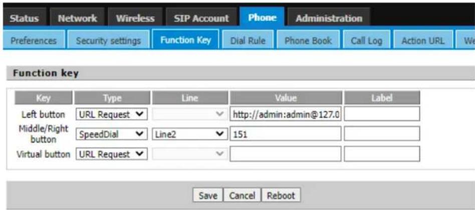
Figure 4-1
4.1.2 IP Direct Dialing
In the same LAN, in an environment without a SIP server, you can set the IP direct dialing,
and then dial the opposite IP addresses to achieve the intercom function.
- There is no need to register the extension number of this phone. Open the web page ->Phone ->Function key
- Select "Speed dial" in the corresponding key type, and fill in the opposite IP address in the value, such as 192.168.50.123
- Click Save to make one click call through i86V
4.2 Answer a Call
When the i86V calls in, the automatic answering is canceled by default, and the device will hear the ring within the set time. If you want to answer, you need to press the answer key. After the answer timed out, the call ends.
4.3 Hang Up the Phone
When the device is in call, you can end the call by pressing the Answer or End key again.
4.4 Auto Answer
The automatic answering function can be enabled for the device. When the device has an incoming call, it will automatically answer the call. You can find all the auto answer numbers in "Phone - Preferences" and turn them on.

Figure 4-2
4.5 Function Keys Setting
Open the "Phone - Function Key" to set the functions of the keys. One click tp trigger the corresponding functions. Currently, the settings supported include speed dial, multicast and URL request. You can check the web configuration page for more details.

Figure 4-3
The following is an explanation of each function:
| Speed Dialing | It call the corresponding extension number |
| Multicast | It can broadcast and talk to multiple devices |
| Action URL | It can trigger access to the entered url address |
Key mapping instructions:
| One keys version (i86V-01) | |
| Middle Key | Mapping device dialing/answering key |
| Virtual Key | As the spare key set for the input interface, there is no entity mapping |
| Double key version (i86V-02) | |
| Left Key | Mapping device the left dialing/answering key |
| Right Key | Mapping device the right dialing/answering key |
| Virtual Key | As the spare key set for the input interface, there is no entity mapping |
Chapter 5 Advanced Functions
This chapter describes the advanced features of the i86V, including the following:
- Multicast Broadcast
- Input Interface Setting
- Onput Interface Setting
• Surveillance Camera Setting
For further information and support, please contact your system administrator.
5.1 Multicast Broadcast
Multicast function is to send the voice message to the set multicast address, and all those who listen to the multicast address can receive the voice message. The function is similar to broadcasting. Using the broadcast function, it is easy and convenient to send announcements to each member of the multicast.
Use Instructions:
- The i86V device sets the multicast initiating address interface through the WEB
Access the phone web page ->Phone ->Function Key, set a function key type as multicast, and the Value is Monitoring Address (Example 224.0.0.1:10001)

Figure 5-1
- The broadcast device can listen to the multicast address and interface through Web settings.
- Select Phone ->Enter Multicast IP ->Enter Monitoring Address (Example 224.0.0.1:10001)

Figure 5-2
- After the configuration is completed, the intercom/phone can initiate multicast by pressing the set multicast key. The device monitoring the address can receive the multicast content without answering
5.2 Input Port Setting
You can meet your personalized scene needs through input devices such as access switches, infrared probes, and vibration sensors.
Path: Phone-Security-Settings

Figure 5-3
The following are the parameters of the input port:
| Input Port Setting | |
| Input Port 1 | Enable or disable the input port |
| Close Trigger Event | When the external device circuit of the i86V changes from the disconnected state to the closed state, a one-time URL is requestedInstructions: Each URL can trigger a request at the same time. Filling in the same URL will trigger the request only once |
| Disconnect Trigger Event | When the external device circuit of the i86V changes from the closed state to the disconnected state, a one-time URL will be requestedInstructions: Each URL can trigger a request at the same time. Filling in the same URL will trigger the request only once |
| Trigger Key Function URL | Left Key: http://user name: password@127.0.0.1/cgi-bin/ConfigManApp.com ?key=L1Right Key: http://user name: password@127.0.0.1/cgi-bin/ConfigManApp.com ?key=L2Virtual key: http://username:password@127.0.0.1/cgi-bin/ConfigManApp.com ?key=L3(The user name and password are admin/admin by default) |
| Trigger Relay Action | Http://username:password@127.0.0.1/cgi-bin/ConfigManApp.com?Key= (trigger command/reset command, see output port setting) |
| Third Party Platform URL | Support filling in third-party platform URL for signal reporting |
5.3 Output Port Setting
You can access input devices such as electric locks and alarms to achieve scene requirements such as opening doors and alarming through the i86V.
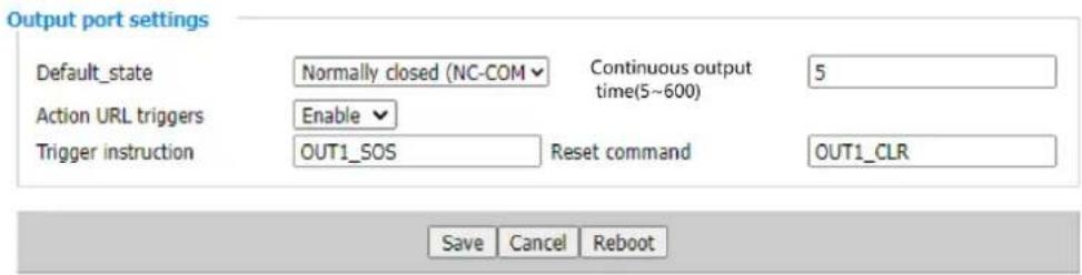
Figure 5-4
The following are the parameters of the output port:
| Output Port Setting | |
| Standard Status | The default state is normally closed (NC-COM connected), and users can customize and modify the default statusNormally closed (NC-COM connected): When the trigger conditions are met, NC-COM is disconnected and NO-COM is connectedNormally open (NO-COM connected): When the trigger conditions are met, NO-COM is disconnected and NC-COM is connected |
| Action URLTrigger | Enable or disable URI triggering.When enabled, the remote device or the local computer sends the request command. If it is correct, the corresponding action will be triggered |
| Trigger ActionDefinition | 1. The default status of the relay is normally closed. When the i86V receives the trigger command, it becomes normally open. After a period of time, it returns to the default status2. The default status of the relay is normally open. When the i86V receives the trigger command, it becomes normally closed. After a period of time, it returns to the default state |
| Reset ActionDefinition | When the duration of relay triggering action has not expired, the output port triggering action will be stopped immediately after receiving the reset command |
| Output Duration | Output port change duration, the default value is 5 seconds, which supports user-defined (5-600s) |
| TriggerInstruction | The default is OUT1_ SOS supports user-defined modification |
| ResetCommand | The default is OUT1_ CLR, support user-defined modification |
| Output TriggerURL | Local trigger:Http://User name: password @ 127.0.0.1/cgi-bin/ConfigManApp.com?Key=Trigger command/Reset commandRemote triggerhttp://User Name: Password@IP Address/cgi-bin/ConfigManApp.com?key=Trigger Command /Reset Command |
| UserName/Password | The default is admin/adminIf you have modified your user name and password, please fill in your modified user name and password |
| IP Address | Enter the IP address you need to control |
5.4 DTMF
DTMF (Dual-Tone Multi-Frequency) signals are used for digital dialing and control functions in telephone systems.
By setting DTMF trigger codes on the i86, you can enable the output port of the device when a specific code, such as "1234," is pressed during a call. This allows you to remotely control operations such as opening doors or triggering alarm lights using DTMF.
Tips: It is important to ensure that both devices have the same DTMF mode, and the extension type registered on the SIP server is also set to the same DTMF mode (usually defaulting to RFC2833).
Output port settings
Default_state
Normally closed (NC-CO)
Continuous output time(5\~600)
5
Trigger By DTMF
Enable
DTMF Trigger Code
1234
DTMF Reset Code
4321
DTMF Reset By
By continus output time
Action URL triggers
Enable
Trigger instruction
OUT1_SOS
Reset command
OUT1_CLR
DTMF configuration
- Log in to the management background of the device
- Open the device->Security Settings->Output Port Settings
- DTMF Trigger -> Select Enable, fill in the trigger code (default is 1234),
- Select the reset method of the output port of the device according to the needs (according to the call time, according to the duration)
- Click Save
Use DTMF
- Presses the speed dial key of i86V to call the indoor phone
- Press the trigger code "1234" on the phone, and the intercom will play DTMF tone at the same time
- Intercom enable output port to realize door opening and other operations

Tips: Here is an example of a FIP15G Plus call, pressing the trigger code.
5.5 Camera Settings
i86V integrates a 2 megapixel high-definition camera, which is set to automatically enable video during calls. It supports a maximum resolution of 1920*1080p for the video capture and display. Users can decode the device's RTSP video stream URL to obtain the video image, thus achieving functions such as security surveillance and video calling.
Tips: Supports video calls with FIP15G Plus
Path: Device -> Camera Settings

Figure 5-5
Video stream push enable : On, Off
Video frame Rate: Default 25. Optional selections include 5, 10, 15, 20, 24, 25, and 30.
Video resolution: 1920*1080、1280×720、704×576、352×288、176×144
Video stream bit rate control: Constant bitrate, Variable bitrate\
Base profile: Base profile, Main profile
Video stream bit rate: Default 4Mbps; Maximum support 14Mbps.
Video stream I frame interval: The interval between two consecutive I-frames in a video stream is the duration or time gap between these frames.
Code stream URL: rtsp://admin:admin@192.168.80.79:8554/unicast
Tips: You can play the video footage using media players like VLC.
Chapter 6 Bulk Deployment
6.1 FDC
In order to manage and configure i86V intercom in large quantities more conveniently and quickly in the local LAN, FDC can provide read/modify device parameters for single or multiple devices.
- The device is up and running and can access a LAN or switch via the WAN port
- Repeat the above steps to connect more devices
- Connect to a computer running FDC software
6.1.1 Bulk Upgrade
Use Instructions:
a. Run the FDC software, in the upper left corner ->Device ->Scan, wait for the scanning to complete, and then you can see the devices connected under the current network

Figure 6-1 Scanning
b. Select in the upper left corner ->Select All: i86V
Chapter 6 Bulk Deployment
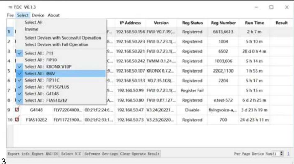
Figure 6-2 Select device
c. Select Device ->Firmware Device - Upgrade Firmware in the upper left corner
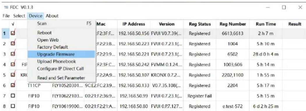
Figure 6-3 Select device
d. Select the version upgrade file in the window
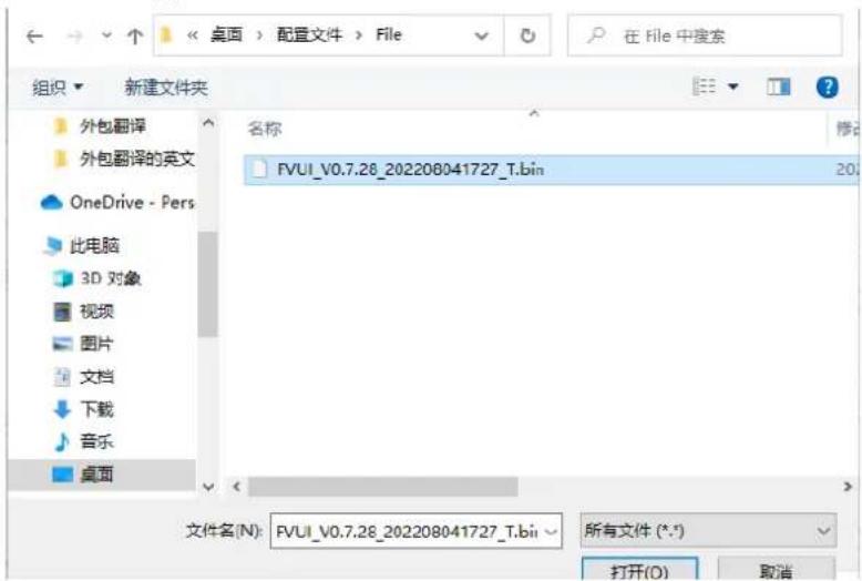
Figure 6-4 Select file
e. Wait for the firmware upgrade to be completed
6.1.2 Export Profile
Device ->Export information ->Save format. csv ->Select the save path ->After export, it can be opened in Excel

Chapter 7 Web Page Configuration
Topic
- Device Status
- Restore Factory Settings
- Firmware Updates
7.1 Device Status
The users can view the current device status of the device on the web page. The status ->Basic includes the following:
● Product Information: (Product Name, MAC address, Hardware version, Loader Version, Firmware Version, Serial Number)
● Line Status: (Line status, primary server, backup server)
● Network Status: (WAN port status, VPN status, wireless status, WiFi switch, Network Mode, channel bandwidth)
● System Status: (Current time, Elapsed time)
7.2 Restore Factory Settings
The device will empty all the configurations on the device, such as the initial account, phone settings, etc., and return to the factory default status.
- Open the device web page ->Administration ->Go down to find the factory settings

Figure 7-1 Restore factory settings
- Click Factory Defalut ->OK -Wait for recovery to be completed
Tips: If you cannot enter the device web, you can press the Reset button and hold it while
the device is powered on until the device emits a beep tone, then release the Reset button and the device starts to restore factory settings. When the device emits a welcome tone, the device reset to factory settings is completed.
7.3 Firmware Updates
The i86V device can be upgraded in the web page.
- Go to the website-> Administration-> Firmware Upgrade Select the file and click Upgrade. You can choose to Ban/Enable Delete the current configuration.
- Click and Save

Figure 7-2


- i86V Series User's Guide
- Copyright
- Trademark
- Warranty
- Warranty
- Disclaimer
- Limitation of Liability
- End User License Agreement
- Patent Information
- Technical Support
- Declaration of Conformity
- Part 15 FCC Rules
- CE
- Safety warning and Attentions
- RF Exposure Statement
- GNU GPL INFORMATION
- Risk Warning Statement
- Table of Contents
- Chapter 1 Forewords....1
- Chapter 2 Overviews....2
- Chapter 3 Getting Started with Users ....6
- Chapter 4 Basic Functions....10
- Chapter 5 Advanced Functions ...... 14
- Chapter 6 Bulk Deployment....22
- Chapter 7 Web Page Configuration....25
- Chapter 1 Forewords
- Instruction
- Chapter 2 Overviews
- Appearance Introductions
- Interface Introductions
- Package Contents
- Documents
- Chapter 3 Getting Started with Users
- Device Installations
- Wiring
- i86V Bottom Box Installation
- Device Boot
- Quick Settings
- Get Device IP
- Broadcast IP Mode
- Web Page Management
- Method 1: PC accesses the device management page
- Method 2: WiFi Configuration of i86V
- Account Registration
- Chapter 4 Basic Functions
- Make a Call
- Number Speed Dialing
- Speed dial configuration
- IP Direct Dialing
- Answer a Call
- Hang Up the Phone
- Auto Answer
- Function Keys Setting
- Chapter 5 Advanced Functions
- Multicast Broadcast
- Use Instructions:
- Input Port Setting
- Output Port Setting
- DTMF
- Output port settings
- DTMF configuration
- Use DTMF
- Camera Settings
- Chapter 6 Bulk Deployment
- FDC
- Bulk Upgrade
- Export Profile
- Chapter 7 Web Page Configuration
- Topic
- Device Status
- Restore Factory Settings
- Firmware Updates
Brand : FlyingVoice
Model : i86V-01
Category : Intercom