
DTP T HD2 4K 230 - Audio/video converter Extron - Free user manual and instructions
Find the device manual for free DTP T HD2 4K 230 Extron in PDF.


| Product Type | Audio/video converter / DTP transmitter |
| Model | DTP T HD2 4K 230 |
| Brand | Extron |
| Video Support | 4K @ 60 Hz with 4:4:4 chroma sampling (up to 10.2 Gbps) |
| HDCP Support | HDCP 2.2 |
| Signal Type | DTP (Digital Twisted Pair) |
| Input Connectors | 1x HDMI (female) |
| Output Connector | 1x RJ-45 (DTP) |
| Audio | Embedded audio pass-through |
| EDID Management | Internal EDID emulation |
| Power Supply | Power over Ethernet (PoE) or external 12 V DC |
| Power Consumption | 5 W (typical) |
| Dimensions (H x W x D) | 1.0" x 4.3" x 3.0" (2.5 cm x 10.9 cm x 7.6 cm) |
| Weight | 0.5 lb (0.2 kg) |
| Enclosure Type | Metal, black |
| Mounting | Furniture mountable with included brackets |
| Operating Temperature | 32 to 104 °F (0 to 40 °C) |
| Compliance | CE, UL, RoHS |
| Maintenance | Clean with a dry, lint-free cloth |
| Warranty | 3 years parts and labor |
| Included Accessories | Mounting brackets, power supply (if not PoE), user manual |
Frequently Asked Questions - DTP T HD2 4K 230 Extron
User questions about DTP T HD2 4K 230 Extron
0 question about this device. Answer the ones you know or ask your own.
Ask a new question about this device
Download the instructions for your Audio/video converter in PDF format for free! Find your manual DTP T HD2 4K 230 - Extron and take your electronic device back in hand. On this page are published all the documents necessary for the use of your device. DTP T HD2 4K 230 by Extron.
USER MANUAL DTP T HD2 4K 230 Extron
Safety Instructions • English
WARNING: This symbol, , when used on the product, is intended to alert the user of the presence of uninsulated dangerous voltage within the product's enclosure that may present a risk of electric shock.
ATTENTION: This symbol, △when used on the product, is intended to alert the user of important operating and maintenance (servicing) instructions in the literature provided with the equipment.
For information on safety guidelines, regulatory compliances, EMI/EMF compatibility, accessibility, and related topics, see the Extron Safety and Regulatory Compliance Guide, part number 68-290-01, on the Extron website, www.extron.com.
This equipment has been tested and found to comply with the limits for a Class A digital device, pursuant to part 15 of the FCC rules. The Class A limits provide reasonable protection against harmful interference when the equipment is operated in a commercial environment. This equipment generates, uses, and can radiate radio frequency energy and, if not installed and used in accordance with the instruction manual, may cause harmful interference to radio communications. Operation of this equipment in a residential area is likely to cause interference. This interference must be corrected at the expense of the user.
ATTENTION: The Twisted Pair Extension technology works with shielded twisted pair (STP) cables only. To ensure FCC Class A and CE compliance, STP cables and STP Connectors are also required.
For more information on safety guidelines, regulatory compliances, EMI/EMF compatibility, accessibility, and related topics, see the “Extron Safety and Regulatory Compliance Guide” on the Extron website.
Copyright
© 2015 Extron Electronics. All rights reserved.
Trademarks
All trademarks mentioned in this guide are the properties of their respective owners.
The following registered trademarks ^® , registered service marks ^(SM) , and trademarks ^(TM) are the property of RGB Systems, Inc. or Extron Electronics:
| Registered Trademarks ^(8) |
| AVTrac, Cable Cubby, CrossPoint, DTP, eBUS, EDID Manager, EDID Minder, Extron, Flat Field, FlexOS, Global Configurator, GlobalViewer, Hideaway, Inline, IP Intercom, IP Link, Key Minder, LockIt, MediaLink, PlenumVault, PoleVault, PowerCage, Pure3, Quantum, SoundField, SpeedMount, SpeedSwitch, System INTEGRATOR, TeamWork, TouchLink, V-Lock, VersaTools, VN-Matrix, VoiceLift, WallVault, WindoWall, XTP, and XTP Systems |
| Registered Service Mark ^(SM) : S3 Service Support Solutions |
| Trademarks ^(TM) |
| AAP, AFL (Accu-Rate Frame Lock), ADSP (Advanced Digital Sync Processing), Auto-Image, CableCover, CDRS (Class D Ripple Suppression), DDSP (Digital Display Sync Processing), DMI (Dynamic Motion Interpolation), Driver Configurator, DSP Configurator, DSVP (Digital Sync Validation Processing), eLink, EQIP, FastBite, FOX, FOXBOX, IP Intercom HelpDesk, LinkLicense, MAAP, MicroDigital, NetPA, ProDSP, QS-FPC (QuickSwitch Front Panel Controller), Room Agent, Scope-Trigger, ShareLink, SIS, Simple Instruction Set, Skew-Free, SpeedNav, Triple-Action Switching, True4K, Vector, WebShare, XTRA, ZipCaddy, ZipClip |
Conventions Used in this Guide
Notifications
The following notifications are used in this guide:
ATTENTION:
- Risk of property damage.
- Risque de dommages matériels.
NOTE: A note draws attention to important information.
TIP: A tip provides a suggestion to make working with the application easier.
Software Commands
Commands are written in the fonts shown here:
^AR Merge Scene,,Op1 scene 1,1 ^B 51 ^W^C
[∅1] R∅0∅4∅03∅0∅04∅0∅08∅0∅06∅0 [∅2] 35 [17] [∅3]
Esc X1 * X17 * X20 * X23 * X21 CE ←
NOTE: For commands and examples of computer or device responses mentioned in this guide, the character "O" is used for the number zero and "O" is the capital letter "o."
Computer responses and directory paths that do not have variables are written in the font shown here:
Reply from 208.132.180.48: bytes=32 times=2ms TTL=32
C:\Program Files\Extron
Variables are written in slanted form as shown here:
ping xxx.xxx.xxx.xxx -t
SOH R Data STX Command ETB ETX
Selectable items, such as menu names, menu options, buttons, tabs, and field names are written in the font shown here:
From the File menu, select New. Click the OK button.
Specifications Availability
Product specifications are available on the Extron website, www.extron.com.
Contents
Introduction.... 1
About the DTP T HD2 4K 230/330....1
Features 1
Application Diagram 2
Installation and Features....3
Mounting the Units 3
Tabletop Use 3
Mounting Kits 3
UL Rack-Mounting Guidelines 4
Front Panel Features....4
Rear Panel Features 5
Twisted Pair Recommendations for DTP
Communication 7
Supported Cables 7
Cable Recommendations 7
Power Supply Wiring 8
SIS Commands 10
Introduction to SIS 10
Host-to-Transmitter
Communications 10
Transmitter-initiated Messages....10
Copyright Information 10
Symbols Used in this Guide....11
Symbol Definitions 11
Error Messages 13
EDID....13
TMDS Output Format 13
DTP T HD2 4K EDID Memory Locations......14
Command and Response Table for SIS
Commands 15
Introduction
This guide describes the function, installation, and operation of the DTP T HD2 4K series of HDMI extenders. Unless otherwise stated, the terms “extender” and “transmitter” are used interchangeably in this guide to refer to all of the products in the series.
This section provides the following information:
• About the DTP T HD2 4K 230/330
- Features
• Application Diagram
About the DTP T HD2 4K 230/330
The DTP T HD2 4K family extends HDMI signals up to 230 feet (70 meters) for the 230 model, and 330 feet (100 meters) for the 330 model over shielded twisted pair (STP) cables. Both models are fully High-bandwidth Digital Content Protection (HDCP) compliant.
These extenders support data rates up to 10.2 Gbps (3.4 Gbps per color) with up to 12-bit deep color and use the EDID Minder feature for EDID management.
The automatic output compatibility correction feature scans each output device to ensure that the output signal is compatible with the color depth and format requirements of the device. Each output is adjusted independently.
Features
Extends HDMI plus control and analog audio up to 230 feet (70 meters) or 330 feet (100 meters) over STP cable (depending on model) — The DTP T HD2 4K series provides high reliability and maximum performance on an economical and easily installed cable infrastructure.
Inputs: One HDMI with buffered input loop-through
Output: One DTP 230 or DTP 330 (depending on model) twisted pair output on RJ-45
Supports computer and video resolutions up to 4K, including 1080p/60 Deep Color
Buffered HDMI input loop-through — The DTP T HD2 4K series features an active local HDMI output for local monitor support or system expansion.
Remote power capability — For simplified installation, the transmitter can be remotely powered by a DTP 230/330-enabled product over the twisted pair connection.
HDCP compliant — Fully supports HDCP-encrypted sources, with selectable authorization for unencrypted content.
EDID Minder automatically manages EDID communication between connected devices — EDID Minder ensures that the source powers up properly and reliably outputs content for display.
Supports EDID and HDCP transmission — DDC channels are actively buffered, allowing continuous communication between source and display.
HDCP authentication and signal presence confirmation — Provides real-time verification of HDCP status for each digital video input and output. This allows for simple, quick, and easy signal and HDCP verification through front panel LEDs or USB, providing valuable feedback to a system operator or helpdesk support staff.
Front panel USB configuration port — Enables easy configuration without having to access the rear panel.
LED indicators for signal presence, HDCP, and power — Provides visual indication of system status for real-time feedback and monitoring of key performance parameters.
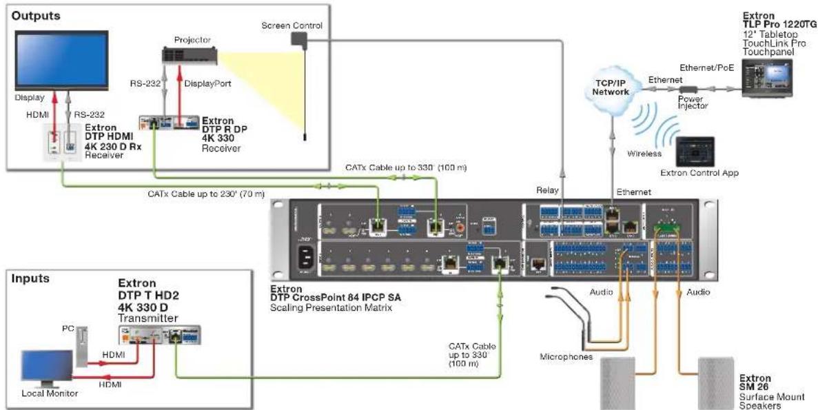
Application Diagram
The diagram below shows a typical application for the DTP T HD2 4K.
flowchart
graph TD
    A["Outputs"] --> B["Display"]
    B --> C["HDMI"]
    C --> D["RS-232"]
    D --> E["Extron DTP HDMI 4K 230 D Rx Receiver"]
    E --> F["Projector"]
    F --> G["DisplayPort"]
    G --> H["Extron DTP R DP 4K 330 Receiver"]
    H --> I["Screen Control"]
    I --> J["Extron TLP Pro 1220TG 12' Tabletop TouchLink Pro Touchpanel"]
    J --> K["TCP/IP Network"]
    K --> L["Ethernet"]
    L --> M["Power Injector"]
    M --> N["Extron Control App"]
    N --> O["Wireless"]
    O --> P["Extron CrossPoint 84 IPCP SA Scaling Presentation Matrix"]
    P --> Q["Relay"]
    Q --> R["Ethernet"]
    R --> S["Microphones"]
    S --> T["Audio"]
    T --> U["Extron SM 26 Surface Mount Speakers"]
    P --> V["CATx Cable up to 330 (100 m)"]
    P --> W["CATx Cable up to 330 (100 m)"]
    P --> X["CATx Cable up to 330 (100 m)"]
    Y["Inputs"] --> Z["Extron DTP T HD2 4K 330 D Transmitter"]
    Z --> AA["PC"]
    AA --> AB["HDMI"]
    AB --> AC["Local Monitor"]
Figure 1. DTP T HD2 4K Application Diagram
Installation and Features
This section of the guide describes the following topics concerned with the installation, setup, and operation of the DTP T HD2 4K series of extenders.
- Mounting the Units
- Front Panel Features
- Rear Panel Features
• Power Supply Wiring
• Twisted Pair Recommendations for DTP Communication
Mounting the Units
ATTENTION:
The DTP T HD2 4K series of extenders can be placed on a table, mounted in a rack, or mounted under a desk or table.
Tabletop Use
Affix the included rubber feet to the bottom of the unit and place it in any convenient location.
Mounting Kits
Mount the unit using any optional compatible mounting kit listed on the Extron website (www.extron.com), in accordance with the directions included with the kit. For rack mounting, see UL Rack-Mounting Guidelines on the next page.
UL Rack-Mounting Guidelines
The following Underwriters Laboratories (UL) requirements pertain to the installation of the unit into a rack.
- Elevated operating ambient temperature — If installed in a closed or multi-unit rack assembly, the operating ambient temperature of the rack environment may be greater than room ambient. Therefore, consider installing the equipment in an environment compatible with the maximum ambient temperature (TMA = +122 °F, +50 °C) specified by Extron.
- Reduced air flow — Installation of the equipment in a rack should be such that the amount of air flow required for safe operation of the equipment is not compromised.
- Mechanical loading — Mounting of the equipment in the rack should be such that a hazardous condition is not achieved due to uneven mechanical loading.
- Circuit overloading — Consideration should be given to the connection of the equipment to the supply circuit and the effect that overloading of the circuits might have on overcurrent protection and supply wiring. Appropriate consideration of equipment nameplate ratings should be used when addressing this concern.
- Reliable Earthing — Reliable earthing of rack-mounted equipment should be maintained. Particular attention should be given to supply a connection other than a direct connection to a branch circuit, such as by using a power strip.
Front Panel Features

A Power status LED — Lights green when power is applied to the unit.
B USB Config port — Used for firmware updates, SIS configuration, and software control.
C Input/Output signal LEDs — Light green when HDCP presence is detected on the HDMI input.
D Input/Output HDCP LEDs — Light green when HDCP presence is detected on the HDMI outputs.
Rear Panel Features
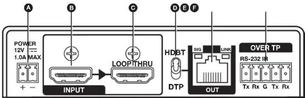
A DC power input connector
B HDMI input
© HDMI Loop Thru
D DTP/HDBaseT configuration switch
E DTP/HDBaseT output
F Over DTP RS-232/IR connector
A DC power input connector — Wire and plug the included external 12 VDC power supply into either this 2-pole connector or the power input connector on the receiver (see page 8 for wiring information).
B HDMI input — Connect a source device to this female HDMI type A connector.
© HDMI Loop Thru — Connect a display to this female HDMI type A connector for local loop-through monitoring of the source signal.
DTP/HDBaseT configuration switch — Set this 2-position, recessed switch to configure the output between DTP and HDBaseT modes. When configured for DTP, use a DTP-compatible receiver. When configured for HDBaseT, use an HDBaseT-compatible receiver.
NOTES:
- When the switch is set to DTP mode, only one power supply is required. A single power supply connected to either a transmitter or compatible receiver can power both units.
- When the switch is set to HDBaseT mode, remote power is disabled and power supplies are required for both transmitter and receiver. Analog audio is enabled, but incompatible with third-party HDBaseT devices.
E DTP/HDBaseT output — Use an STP cable to connect this output to the input of a compatible receiver (see Twisted Pair Recommendations for DTP Communication on page 7 for more information).
ATTENTION:
RS-232 Over TP port — To pass bidirectional serial control between DTP-compatible or HDBaseT-compatible devices, connect a control device to the 5-pole captive screw connector. This port includes only the 3 poles labeled "RS-232" (see image below for wiring instructions).
IR Over TP port — To transmit and receive IR signals, connect a control device to the 5-pole captive screw connector. This port includes only the 2 poles labeled "IR" and shares the ground pole with the RS-232 port (see image below for wiring instructions).


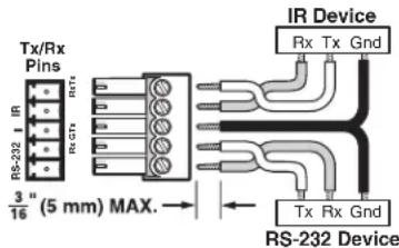
NOTE: RS-232 and IR data can be transmitted simultaneously.
Twisted Pair Recommendations for DTP Communication
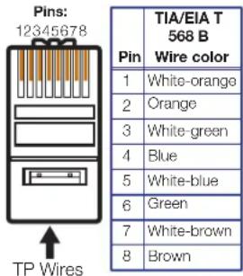
Use the following pin configurations for shielded twisted pair cables.
Supported Cables
The transmitters are compatible with shielded twisted pair cable (F/UTP, SF/UTP, and S/FTP).
ATTENTION:
Cable Recommendations
Extron recommends using the following practices to achieve full transmission distances and reduce transmission errors.
- Use the following Extron XTP DTP 24 SF/UTP cables and connectors for the best performance:
• XTP DTP 24/1000 Non-Plenum 1000' (305 m) spool 22-236-03
• XTP DTP 24P/1000 Plenum 1000' (305 m) spool 22-235-03
• XTP DTP 24 Plug Package of 10 101-005-02
- If not using XTP DTP 24 cable, at a minimum, Extron recommends 24 AWG, solid conductor, STP cable with a minimum bandwidth of 400 MHz.
- Terminate cables with shielded connectors to the TIA/EIA-T568B standard.
- Limit the use of more than two pass-through points, which may include patch points, punch down connectors, couplers, and power injectors. If these pass-through points are required, use shielded couplers and punch down connectors.
NOTE: When using shielded twisted pair cable in bundles or conduits, consider the following:
- Do not exceed 40% fill capacity in conduits.
- Do not comb the cable for the first 20 meters, where cables are straightened, aligned, and secured in tight bundles.
- Loosely place cables and limit the use of tie wraps or hook-and-loop fasteners.
- Separate twisted pair cables from AC power cables.
Power Supply Wiring
NOTES:
- Only one power supply is required. A single power supply connected to either a transmitter or compatible receiver can power both units.
- Remote power is only available when the unit is set to DTP mode. When the unit is set to HDBaseT mode, remote power and analog audio are disabled.
- A power supply is included with each individually-packaged transmitter.
- Do not tin the power supply leads before installing them in the direct insertion connector. Tinned wires are not as secure in the connectors and could be pulled out.
Figure 2 shows how to wire the connector.

Figure 2. Power Connector Wiring
CAUTION: The wires must be kept separate while the power supply is plugged in. Remove power before wiring.
- Always use a power supply supplied and or specified by Extron. Use of an unauthorized power supply voids all regulatory compliance certification and may cause damage to the supply and the end product.
- If not provided with a power supply, this product is intended to be supplied by a power source marked "Class 2" or "LPS" and rated at 12 VDC and a minimum of 1.0 A.
- The installation must always be in accordance with the applicable provisions of National Electrical Code ANSI/NFPA 70, article 725 and the Canadian Electrical Code part 1, section 16. The power supply shall not be permanently fixed to building structure or similar structure.
- Power supply voltage polarity is critical. Incorrect voltage polarity can damage the power supply and the unit. The ridges on the side of the cord (see figure 2 on previous page) identify the power cord negative lead.
- To verify the polarity before connection, plug in the power supply with no load and check the output with a voltmeter.
- The length of the exposed (stripped) copper wires is important. The ideal length is 3/16 inch (5 mm). Longer bare wires can short together. Shorter wires are not as secure in the connectors and could be pulled out.
- Unless otherwise stated, the AC/DC adapters are not suitable for use in air handling spaces or in wall cavities.
This section provides information about the SIS commands that are used to configure the DTP T HD2 4K series. The following topics are discussed:
• Introduction to SIS
• Symbols Used in this Guide
• DTP T HD2 4K EDID Memory Locations
• Command and Response Table for SIS Commands
Introduction to SIS
The transmitter can be set up and controlled remotely via Extron SIS commands that are issued from a host computer running the Extron DataViewer utility or other control system. The host device can be connected to the mini USB config port on the front panel.
NOTE: The wiring in the RS-232 cables crosses over so that the unit transmit (Tx) wire connects with the control device receive (Rx) and vice versa.
Host-to-Transmitter Communications
SIS commands consist of strings (one or more characters per command field). No special characters are required to begin or end a command sequence. Unless otherwise stated, upper and lower case characters can be used interchangeably. Most responses from the transmitter end with a carriage return and a line feed (CR/LF = ←), which signals the end of the response character string. When the device determines that a command is valid, it executes the command and sends a response to the host device.
Transmitter-initiated Messages
When a local event such as a change in signal status takes place, the transmitter responds by sending a message to the host, indicating the status change. No response is required from the host.
Copyright Information
The copyright message is displayed upon connecting to a transmitter USB.
←© Copyright 20yy, Extron Electronics, DTP T HD2 4K 230/330, Vx.xx,60-xxxx-01
20yy is the year the currently installed firmware was released, Vx.xx is the firmware version number, and 60-xxxx-01 is the catalog part number.
Symbols Used in this Guide
When programming in the field, certain characters are most conveniently represented by their hexadecimal rather than their ASCII values. The table below shows the hexadecimal equivalent of each ASCII character:
| ASCII to HEX Conversion Table | Esc | 1B | CR | ∅D | LF | ∅A | |||||||||
| mm | 20 | ! | 21 | " | 22 | # | 23 | 24 | % | 25 | & | 26 | ' | 27 | |
| ( | 28 | ) | 29 | * | 2A | + | 2B | , | 2C | - | 2D | . | 2E | / | 2F |
| ∅ | 30 | 1 | 31 | 2 | 32 | 3 | 33 | 4 | 34 | 5 | 35 | 6 | 36 | 7 | 37 |
| 8 | 38 | 9 | 39 | : | 3A | ; | 3B | < | 3C | = | 3D | > | 3E | ? | 3F |
| @ | 40 | A | 41 | B | 42 | C | 43 | D | 44 | E | 45 | F | 46 | G | 47 |
| H | 48 | I | 49 | J | 4A | K | 4B | L | 4C | M | 4D | N | 4E | O | 4F |
| P | 50 | Q | 51 | R | 52 | S | 53 | T | 54 | U | 55 | V | 56 | W | 57 |
| X | 58 | Y | 59 | Z | 5A | [ | 5B | \ | 5C | ] | 5D | ^ | 5E | - | 5F |
| ` | 60 | a | 61 | b | 62 | c | 63 | d | 64 | e | 65 | f | 66 | g | 67 |
| h | 68 | i | 69 | j | 6A | k | 6B | l | 6C | m | 6D | n | 6E | o | 6F |
| p | 70 | q | 71 | r | 72 | s | 73 | t | 74 | u | 75 | v | 76 | w | 77 |
| x | 78 | y | 79 | z | 7A | { | 7B | | | 7C | } | 7D | ~ | 7E | DEL | 7F |
Table 1. ASCII to HEX Conversion Table
Symbol Definitions
- = Space
← = Carriage return with line feed
| or ← = Carriage return with no line feed
W
x1 = Output selection 1 through maximum number of outputs
x2 = Output status 0 = disabled/off/undetected
1 = enabled/on/detected
x3 = Video color bit depth = auto (based on EDID of sink)
1 = force 8-bit
X4 = EDID memory location 1-16 (default is 9)
See the DTP T HD2 4K EDID Memory
Locations table on page 14.
X5 = EDID data as 256 bytes of hex data (text representation)
X6 = Native resolution and refresh rate Example: 1600x1200 @60Hz (translated from hex)
[X7] = Controller firmware version to the second decimal place
X8 = Unit name: Up to 24 alphanumeric characters (including hyphen [-]) No spaces allowed No distinction between upper and lower case letters
First character must be a letter Last character cannot be a hyphen (-) Default is model name
[X9] = Video mute 0 = video mute disabled
1 = video mute (TMDS)
2 = video and sync mute
Esc or = Escape
X10 = TMDS output format
∅ = Auto (default), pass through if HDMI sink, force DVI format if DVI sink
1 = DVI RGB 444
2 = HDMI RGB "Full"
3 = HDMI RGB "Limited"
[X11] = HDCP output mode
∅ = Encrypt as required by input
(Continuous trials for HDMI sinks, attempt for
10 seconds on DVI sinks, then fail)
1 = Always encrypt
(Continuous trials for HDMI sinks, attempt for
10 seconds on DVI sinks, then fail)
2 = Encrypt as required by input
(Continuous trials for HDMI sinks and DVI sinks)
3 = Always encrypt
(Continuous trials for HDMI sinks and DVI sinks)
X12 = DTP/HDBaseT switch position
∅ = DTP mode
1 = HDBaseT mode
X13 = Verbose mode
∅ = Clear/none (default for telnet)
1 = Verbose mode (default for USB)
2 = Tagged responses for queries
3 = Verbose mode and tagged responses for queries
Error Messages
E01 — Invalid output channel number (too large)
E10 — Invalid command
E13 — Invalid value (too large)
EDID
User assigned mode
In user assigned mode, the user can select from 14 factory loaded EDID files, each categorized by rate type (IT or CE), video format (DVI or HDMI), audio type (2-Ch), and native resolution. The unit retains this setting after a power cycle.
Additionally, two user-loaded slots are available to save the EDID of any connected display. EDID saved to these slots are retained after a power cycle. Upon a factory reset, these EDID revert to the factory default (720p @ 60 Hz, 2-Ch audio).
A table showing the factory loaded EDID options is shown on the following page. The EDID memory location is labelled 4 for consistency with the value in the SIS commands.
TMDS Output Format
The TMDS output format has three components:
• Video format (HDMI or DVI)
• Colorspace (RGB 4:4:4, YUV 4:2:2, or YUV 4:4:4)
• Quantization range (full [0-255] or limited [16-235]).
By default, the output format will be configured for AUTO, which will automatically force RGB 4:4:4 Full, with the video format being dependent on the source signal and the sink capabilities.
NOTE: When the source signal is detected as 4K/UHD @ 60Hz with YUV 4:2:0 (based on AVI infoframe data), it must pass unaltered, overriding the TMDS output format setting. If the TMDS output format is changed while this signal type is passing, the setting will be applied, but with no observable change. The TMDS output format will resume as configured when the source signal changes to a signal other than 4K/UHD @ 60 Hz with YUV 4:2:0.
DTP T HD2 4K EDID Memory Locations
| X4 | Native Resolution | Refresh Rate Rate | Type Video | Format Audio Type | |
| 1 | 1280x800 60 Hz IT HDMI 2 | -Ch | |||
| 2 | 1440x900 60 Hz IT HDMI 2 | -Ch | |||
| 3 | 1600x900 60 Hz IT HDMI 2 | -Ch | |||
| 4 | 1680x1050 60 Hz IT HDMI | 2-Ch | |||
| 5 | 1920x1200 60 Hz IT HDMI | 2-Ch | |||
| 6 | 2560x1440 60 Hz IT HDMI | 2-Ch | |||
| 7 | 2560x1600 60 Hz IT HDMI | 2-Ch | |||
| 8 | 720p 50 Hz CE HDMI 2-Ch | ||||
| 9* | 720p 60 Hz CE | HDMI 2-Ch | |||
| 10 | 1080p | 50 Hz CE HDMI 2-Ch | |||
| 11 | 1080p | 60 Hz CE HDMI 2-Ch | |||
| 12 | 4K / UHD | 30 Hz CE HDMI 2-Ch | |||
| 13 | Output 1 | ||||
| 14 | Output 2 | ||||
| 15 | User Loaded Slot 1 | ||||
| 16 | User Loaded Slot 2 | ||||
| *Default | |||||
Command and Response Table for SIS Commands
| Command ASCII Command(host to unit) | Response(unit to host) | Additional Description | |
| Video Mute | |||
| Video mute single output | 1*9B/b | Vmt1*9 | 9=0-2 (default is 0) |
| Video mute all outputs | 9B/b Vmt9 | ||
| Query video mute status | B/b 99 | Video mute status of outputs 1-2Verbose Mode 2/3 | |
| Vmt99 | |||
| Embedded Audio Mute | |||
| Audio mute single output | 1*x2Z/z Amt1*x2 | Audio mute of embedded audio only | |
| Audio mute all outputs | 2Z/z Amt2 | ||
| Query audio mute status | Z/z 22 | Audio mute status of outputs 1-2Verbose Mode 2/3 | |
| Amt22 | |||
| TMDS Output Format | |||
| Set format for single output | Esc1*x10VTPO | Vtpo1*x10 | 10=0-7 (default is 0) |
| Set format for all outputs | Esc10VTPO Vtpo10 | ||
| Query format settings | EscVTPO x1010 | Outputs 1-2Verbose Mode 2/3 | |
| Vtpo1010 | |||
| Video Color Bit Depth | |||
| Set video bit depth for a single output | EscV1*x3BITD | BitdV1*x3 | 3=0 (default) or 1 |
| Set video bit depth for all outputs | EscV3BITD | BitdV3 | 3=0 (default) or 1 |
| Query video bit depth for all outputs | EscVBITD | 33 | Video bit depth of outputs 1-2Verbose Mode 2/3 |
| BitdV33 | |||
| NOTES: 1=Output selection 2=Output status 3=Video color bit depth 9=Video mute 10=TMDS output format | 1 through max number of outputs (disabled/off/undetected, default), 1 (enabled/on/detected) = auto (based on EDID of sink), 1 = force 8-bit = disabled, 1 = video (TMDS), 2 = video and sync = Auto (default) 1 = DVI RGB 4442 = HDMI RGB “Full”3 = HDMI RGB “Limited”4 = HDMI YUV 444 “Full”5 = HDMI YUV 444 “Limited”6 = HDMI YUV 422 “Full”7 = HDMI YUV 422 “Limited” | ||
| HDCP Output Mode | |||
| Set HDCP output mode for a single output | EscS × 1 * × 11 HDCP← | HdcpS × 1 * × 11 ← | × 11 = -3 ( is default) |
| Set HDCP output mode for all outputs | EscS × 11 HDCP← | HdcpS × 11 ← | × 11 = -3 ( is default) |
| Query HDCP output mode for all outputs | EscSHDCP← × 11 * × 11 ← | HdcpS × 11 * × 11 ← | Video bit depth of outputs 1-2Verbose Mode 2/3 |
| Signal Status (unsolicited) | |||
| Request all signal status | EscLS← × 2 * × 2 * × 2 ← | Sig × 2 * × 2 * × 2 ← | Input * Outputs 1-2Verbose Mode 2/3 |
| Request all HDCP status | EscHDCP← × 2 * × 2 * × 2 ← | Hdcp × 2 * × 2 * × 2 ← | Input * Outputs 1-2Verbose Mode 2/3 |
| HDCP Authorized Device | |||
| HDCP authorization enable/disable | EscE × 2 HDCP← | HdcpE × 2 ← | × 2 = (disabled), 1 (enabled, default) |
| Query HDCP authorization status | EscEHDCP← | × 2 ←Hdcp × 2 ← | × 2 = (disabled), 1 (enabled, default)Verbose Mode 2/3 |
NOTES:
| x1 = Output selection | 1 through max number of outputs |
| x2 = Output status | ∅ = disabled/off/undetected (default), 1 = (enabled/on/detected) |
| x11 = HDCP output mode | ∅ = Encrypt as required by input(Continuous trials for HDMI sinks, attempt for 10 seconds on DVI sinks, then fail)1 = Always encrypt(Continuous trials for HDMI sinks, attempt for 10 seconds on DVI sinks, then fail)2 = Encrypt as required by input(Continuous trials for HDMI sinks and DVI sinks)3 = Always encrypt(Continuous trials for HDMI sinks and DVI sinks) |
| Command ASCII Command(host to unit) | Response(unit to host) | Additional Description | |
| EDID Minder | |||
| Assign EDID to input | EscA4EDID← | EdidA4← | X4= EDID memory location (1-16)see the DTP T HD2 4K EDIDMemory Locations table on page 14(default is 9) |
| View EDID assignment | EscAEDID← | X4← | |
| EdidA4← | Verbose Mode 2/3 | ||
| Save EDID of output to user location | EscS1*X4EDID← | EdidS1*X4← | Store the EDID of output X1into EDIDmemory location X4(58 or 59) |
| View/Read EDID in Hex | EscREDID← | X5← | Display currently assigned EDID in Hex |
| EdidRX5 | Verbose 2/3 | ||
| View EDID native resolution | EscNEDID← | X6← | Resolution and refresh rate of currently selected EDID |
| EdidNX6 | Verbose Mode 2/3Example: 1600x1200@60Hz | ||
| Unit Name | |||
| Set unit name | EscX8CN← Ipn•X8← | X8= Up to 24 alphanumeric characters, including "-" | |
| Set unit name to factory default | Esc•CN← | Ipn•{Default}← | Example:DTP-T-HD2-330(Model name) |
| View unit name | EscCN← | X8← | |
| Ipn•X8← | Verbose Mode 2/3 | ||
| Other | |||
| Set verbose mode | EscX13CV← | VrbX13← | ∅-3 (1 is default) |
| Query verbose mode | EscCV← | X13← | |
| VrbX13← | Verbose Mode 2/3 | ||
| Query DTP mode | Esc01HDBT← X12← | ||
| HdbtOX12← | Verbose Mode 2/3 | ||
| Request part number | N/n 6∅-1491-12← | DTP T HD2 4K 230 | |
| 6∅-1491-52← | DTP T HD2 4K 330 | ||
| Query firmware version | Q/q | X7← | |
| Query firmware version with build | *Q/q x.xx.xxxx← | Firmware build with 2 decimals | |
| Reset settings | EscZXXX← Zpx← | ||
NOTES:
| X1 = Output selection | 1 through max number of outputs |
| X4 = EDID memory location | 1 - 16 (9 is default), see table on page 14 |
| X5 = EDID data as 256 bytes of hex data (text representation) | |
| X6 = Native resolution and refresh rate (translated from hex) | Example: 1600x1200@60Hz |
| X8 = Unit name | Up to 24 alphanumeric characters (including hyphen [-]) |
| X12 = DTP/HDBaseT switch position | ∅ = DTP mode, 1 = HDBaseT mode |
| X13 = Verbose mode | ∅ = Clear/none (default for telnet) |
| 1 = Verbose mode (default for RS-232 and USB) | |
| 2 = Tagged responses for queries | |
| 3 = Verbose mode and tagged responses for queries |
Extron Warranty
Extron Electronics warrants this product against defects in materials and workmanship for a period of three years from the date of purchase. In the event of malfunction during the warranty period attributable directly to faulty workmanship and/or materials, Extron Electronics will, at its option, repair or replace said products or components, to whatever extent it shall deem necessary to restore said product to proper operating condition, provided that it is returned within the warranty period, with proof of purchase and description of malfunction to:
and Central America:
Extron Electronics
1230 South Lewis Street
Anaheim, CA 92805
U.S.A.
Japan:
Extron Electronics, Japan
Kyodo Building, 16 Ichibancho
Chiyoda-ku, Tokyo 102-0082
Japan
Europe and Africa:
Extron Europe
Hanzeboulevard 10
3825 PH Amersfoort
The Netherlands
China:
Extron China
686 Ronghua Road
Songjiang District
Shanghai 201611
China
Asia:
Extron Asia Pte Ltd
135 Joo Seng Road, #04-01
PM Industrial Bldg.
Singapore 368363
Singapore
Middle East:
Extron Middle East
Dubai Airport Free Zone
F13, PO Box 293666
United Arab Emirates, Dubai
This Limited Warranty does not apply if the fault has been caused by misuse, improper handling care, electrical or mechanical abuse, abnormal operating conditions, or if modifications were made to the product that were not authorized by Extron.
NOTE: If a product is defective, please call Extron and ask for an Application Engineer to receive an RA (Return Authorization) number. This will begin the repair process.
USA: 714.491.1500 or 800.633.9876 Europe: 31.33.453.4040
Asia: 65.6383.4400 Japan: 81.3.3511.7655
Units must be returned insured, with shipping charges prepaid. If not insured, you assume the risk of loss or damage during shipment. Returned units must include the serial number and a description of the problem, as well as the name of the person to contact in case there are any questions.
Extron Electronics makes no further warranties either expressed or implied with respect to the product and its quality, performance, merchantability, or fitness for any particular use. In no event will Extron Electronics be liable for direct, indirect, or consequential damages resulting from any defect in this product even if Extron Electronics has been advised of such damage.
Please note that laws vary from state to state and country to country, and that some provisions of this warranty may not apply to you.
| Extron Headquarters+1.800.633.9876 (Inside USA/Canada Only)Extron USA - West Extron USA - East+1.714.491.1500 +1.919.850.1000+1.714.491.1517 FAX +1.919.850.1001 FAX | Extron Europe+800.3987.6673(Inside Europe Only)+31.33.453.4040+31.33.453.4050 FAX | Extron Asia-65.6383.4100-65.6383.4864 FAX | Extron Japan-81.3.3511.7855-81.3.3511.7856 FAX | Extron China+96.21.3780.1568+86.21.3780.1568 FAX | Extron Middle East+071.4.299.1800+1971.4.299.1880 FAX | Extron Korea+82.2.344.4.1571+182.2.3444.1575 FAX | Extron India1800.3070.3777(Inside India Only)+91.80.3055.3777+91.80.3055.3737 FAX |
- Safety Instructions • English
- Copyright
- Trademarks
- Conventions Used in this Guide
- Notifications
- ATTENTION:
- Software Commands
- Specifications Availability
- Contents
- Introduction.... 1
- Installation and Features....3
- SIS Commands 10
- Introduction
- About the DTP T HD2 4K 230/330
- Features
- Application Diagram
- Installation and Features
- Mounting the Units
- Tabletop Use
- Mounting Kits
- UL Rack-Mounting Guidelines
- Rear Panel Features
- NOTES:
- Twisted Pair Recommendations for DTP Communication
- Supported Cables
- Cable Recommendations
- Power Supply Wiring
- Introduction to SIS
- Host-to-Transmitter Communications
- Transmitter-initiated Messages
- Copyright Information
- Symbols Used in this Guide
- Symbol Definitions
- Error Messages
- EDID
- User assigned mode
- TMDS Output Format
- Extron Warranty
- Japan:
- Europe and Africa:
- China:
- Asia:
- Middle East:
Brand : Extron
Model : DTP T HD2 4K 230
Category : Audio/video converter