
IN1806 - Commutateur audiovisuel Extron - Free user manual and instructions
Find the device manual for free IN1806 Extron in PDF.


| Product Type | Multi-format Presentation Switcher/Scaler |
| Brand | Extron |
| Model | IN1806 |
| Inputs | 6 (HDMI, VGA, DisplayPort, composite video, S-video, audio) |
| Outputs | 1 HDMI, 1 VGA, 1 audio |
| Max Resolution | 1920x1200 (WUXGA) or 1080p |
| Scaling | Yes, with motion-adaptive deinterlacing |
| EDID Management | Selectable EDID modes |
| HDCP Support | Yes, HDCP 1.4 compliant |
| Dimensions (H x W x D) | 1.7 in (4.3 cm) x 17 in (43.2 cm) x 6.5 in (16.5 cm) |
| Weight | 4.0 lb (1.8 kg) |
| Power Consumption | 30 W |
| Power Supply | 100-240 VAC, 50/60 Hz, internal |
| Control | Front panel, RS-232, IR, Ethernet |
| Rack Mountable | Yes, 1U, with included brackets |
| Operating Temperature | 32 to 104 °F (0 to 40 °C) |
| Maintenance | Clean with a soft, dry cloth. Do not use liquids. |
| Safety | Follow all warning labels; use grounded outlets; avoid moisture. |
| Spare Parts / Repairability | Contact Extron support for service or replacement parts. |
| Warranty | 3 years parts and labor |
Frequently Asked Questions - IN1806 Extron
User questions about IN1806 Extron
0 question about this device. Answer the ones you know or ask your own.
Ask a new question about this device
Download the instructions for your Commutateur audiovisuel in PDF format for free! Find your manual IN1806 - Extron and take your electronic device back in hand. On this page are published all the documents necessary for the use of your device. IN1806 by Extron.
USER MANUAL IN1806 Extron
IN1806 • Setup Guide
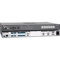
The Extron IN1806 is a six input seamless scaling presentation switcher that supports signal resolutions up to 4K @ 60 Hz at 4:4:4. It features DisplayPort and HDMI inputs, an HDMI output, and a mirrored Extron DTP2 output for extending video, audio, and control signals up to 330 feet (100 meters) over a shielded CATx cable. The IN1806 delivers high image quality, fast and reliable switching, Extron ProDSP audio processing, seamless video transition effects, logo keying, and HDMI loop-out. The scaler can be controlled and configured over Ethernet, RS-232, or USB.
This guide provides instructions for an experienced user to set up and configure the IN1806 scaler. It covers how to perform basic setup operations using the front panel controls and selected Simple Instruction Set (SISTM) commands.
NOTES:
- For full installation, configuration, menus, connector wiring, and operation details, see the IN1806 and IN1808 Series User Guide at www.extron.com.
- The IN1806 can also be configured via the Extron Product Configuration Software (PCS), available at www.extron.com. For information on using PCS, see the IN1806 and IN1808 Series Help File.
Installation
Rear Panel Features

A AC power connector
B DisplayPort input connector (input 1)
© HDMI (with CEC) loop out connector
D HDMI (with CEC) output connector (1A)
E DTP2/XTP/HDBaseT (with CEC) output connector (1B)
F Over TP IR pass-through connector
G Analog line audio inputs 3 and 4
H Analog mic/line audio inputs 1 and 2 and adjacent phantom power LEDs
I Analog line audio outputs 1 through 4
J LAN connector
Remote RS-232 port
Reset LED
M Reset button
N Aux mono or stereo analog line audio input connector
HDMI inputs 2 through 6
Figure 1. Rear Panel Connectors - IN1806
Mounting and Cabling
Step 1 — Mount the device
a. Turn off or disconnect all equipment power sources.
b. Mount the IN1806 to a rack using the pre-installed side mounting brackets, or remove the brackets and use an optional 19-inch kit for under-desk mounting (see the instructions provided with the mounting kit, available at www.extron.com).
Step 2 - Connect inputs
a. Make the following video input connections as needed:
- Connect a DP source to the Input 1 DisplayPort connector (see figure 1, B).
- Connect digital HDMI or DVI (with an appropriate adapter) sources to HDMI input connectors 2 through 6 (O).
b. Connect analog audio sources to:
- The 5-pole captive screw line audio input connectors 3 and 4 (G) and the Aux connector (N) for balanced or unbalanced stereo audio. The Aux Line input (N) is shared and can be associated with one or more video inputs.
- Connect balanced or unbalanced mic or line level inputs to 3-pole Mic/Line captive screw connectors 1 and 2 (H). These inputs support optional +48 VDC phantom power, which is indicated by the LEDs at the left of the connectors.
Step 3 — Connect outputs
Make the following output connections as needed:
- Connect an HDMI, or DVI with an appropriate adapter, display to HDMI/CEC output connector 1A (see figure 1, D, on the previous page). Connect a display to the HDMI Loop Out connector (C).
- Connect a DTP/XTP matrix switcher/HDBaseT compatible receiver to output connector 1B (E). For cable wiring and recommendations, see “Twisted Pair Recommendations for DTP, XTP, and HDBaseT Communication.”
- Connect balanced or unbalanced analog audio output devices to one or both 5-pole captive screw output connector pairs 1 and 2, or 3 and 4 (1) (see Audio Wiring on the next page for more information).
To pass infrared data, connect a control device to the 3-pole IR Over DTP captive screw connector (see IR Over TP Wiring, on the next page). Alternatively, insert RS-232 communication to a DTP/HDBaseT endpoint via Ethernet (see the IN1806 and IN1808 Series User Guide for more information).
Step 4 — Connect control devices
- To control the IN1806 through Ethernet, connect a LAN or WAN to the RJ-45 LAN connector (J). To wire the RJ-45 connector to the cable, see “Twisted Pair Recommendations for DTP, XTP, and HDBaseT Communication.” The default IP address of the scaler is 192.168.254.254, the default subnet mask is 255.255.255.0, and the default gateway address is 0.0.0.0.
- For serial RS-232 control, connect a host device to the 3-pole captive screw connector (K). The default baud rate is 9600.
- For control through USB, connect a host device to the front panel USB mini-B port (see figure 2, A, on the next page).
Step 5 — Connect power
Connect a 100 to 240 VAC, 50-60 Hz power source to the AC power connector (see figure 1, A, on the previous page).
Twisted Pair Recommendations for DTP, XTP, and HDBaseT Communication
Extron recommends using the following practices to achieve full transmission distances and reduce transmission errors:
- Use Extron XTP/DTP 24 SF/UTP cable for the best performance. At a minimum, Extron recommends 24 AWG, solid conductor, STP cable with a minimum bandwidth of 400 MHz.
- Terminate cables with shielded connectors to the TIA/EIA-T568B standard (shown at right).
- Limit the use of more than two pass-through points, which may include patch points, punch down connectors, couplers, and power injectors. If these pass-through points are required, use shielded couplers and punch down connectors.

| TIA/EIA-T568B | |
| Pin | Wire Color |
| 1 | White-orange |
| 2 | Orange |
| 3 | White-green |
| 4 | Blue |
| 5 | White-blue |
| 6 | Green |
| 7 | White-brown |
| 8 | Brown |
ATTENTION:
NOTE: When using shielded twisted pair cable in bundles or conduits, consider the following:
- Do not exceed 40% fill capacity in conduits.
• Do not comb the cable for the first 20 meters, where cables are straightened, aligned, and secured in tight bundles. - Loosely place cables and limit the use of tie wraps or hook-and-loop fasteners.
- Separate twisted pair cables from AC power cables.
Firmware Updates
Download firmware updates from the Extron website and upload them via the internal web pages or PCS.
Audio Wiring
Wire the audio input and output connectors as shown at right. Use the supplied tie wrap to strap the audio cable to the extended tail of the connector.
ATTENTION:
NOTE: The length of exposed wires is critical. The ideal length is 3/16 inch (5 mm).
IR Over TP Wiring
To transmit and receive IR signals, connect a control device to the three-pole Over TP IR connector (G, Tx, and Rx).
NOTE: RS-232 data can be inserted via Ethernet only (see the IN1806 and IN1808 Series User Guide for details).
Audio Inputs and Outputs 1 – 4 and Aux


Unbalanced Audio InputBalanced Auc

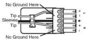
Unbalanced Audio Output
Balanced Audio Output
Mic/Line Inputs 1 and 2
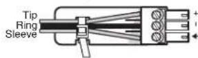
Balanced Audio Input

Unbalanced Audio Input

Do not tin the wires!
Front Panel Overview

Figure 2. Front Panel Features — IN1806
A Config port
B Input selection buttons
© Logo button
D Signal and Status LEDs
E Menu and Enter buttons
F Navigation buttons
G Mic knob and LEDs
H Volume knob and LEDs
A Front panel configuration port — Connect a host device to the USB mini-B port for device configuration, control, file transfers, and firmware upgrades.
B Input selection buttons (1-6) — Press one of these buttons to select an input. The buttons light amber for audio and video, green for video only, or red for audio only.
Logo button — Press this button to enable or disable the most recently selected logo slot. Press and hold the button to select logo slot 1 through 6 using the input selection buttons (slots 7-16 are available via SIS commands only). See the IN1806 and IN1808 Series User Guide at www.extron.com for more information about logos.
D Signal and Status LEDs
- Input signal LEDs — These six LEDs light green for their corresponding inputs when active video content is detected on that input.
- Output signal LEDs — Output LEDs 1A, 1B, and Loop light green when active video is being output, and blink amber when output video and sync are disabled.
• Input HDCP LEDs — These six LEDs light green for each input signal that is HDCP-encrypted.
• Output HDCP LEDs — These three LEDs light green for an output when it is currently HDCP-encrypted.
• DTP2 and DTP Output LEDs — These LEDs light green if DTP or DTP2 power has been enabled on DTP output 1B.
Menu and Enter buttons — Press these buttons to access and navigate the on-screen display (OSD) menu system.
F Navigation buttons — Press these buttons to navigate through the on-screen display menu system or change settings.
G Mic knob and LED indicators — Rotate the knob to adjust the microphone level. The eight LED indicators light according to the level being adjusted. The LEDs light in order from bottom to top to indicate steps from 1% (-99 dB) to 99% (-1 dB). The bottom LED blinks when the volume is muted. The top LED blinks when the volume is at 100% (0 dB).
H Volume knob and LED indicators — Rotate the knob to adjust the program or output volume level.
IN1806 Configuration
To configure the IN1806, use the front panel controls, the on-screen display (OSD) menu, internal web pages, PCS, or SIS.
On-screen Display (OSD) Menu System
To configure IN1806 using the OSD menu, connect a display to either HDMI output 1A or to a DTP/XTP matrix switcher/HDBaseT compatible device. The OSD menu consists of nine submenus accessed using the front panel Menu or Enter button (see the example at right).
Extron Product Configuration Software
To configure IN1806 scaler using PCS, install the software (available on the Extron website, www.extron.com) to a PC connected to the IN1806 via Ethernet or the front panel USB Config port. After the installation, start the program. For full instructions, press
Internal Web Pages
To configure the IN1806 using the factory-installed web pages in a web browser (see the example at right), connect the LAN connector on the IN1806 to a LAN or WAN. The default IP address is 192.168.254.254.
| Extron | IN1806 | |
| DEVICE INFO | IN2: Input Mode | HDMI |
| QUICK SETUP | IN2: EDID | Auto |
| PICTURE CONTROLS | Output Rate | 1080p @ 60 Hz |
| INPUT | Audio Mute | Off |
| OUTPUT | ||
| AUDIO | Test Pattern | Off |
| ADVANCED | DHCP Mode | Off |
| COMMUNICATIONS | IP Address | 192.168.254.254 |
| Input 2 Scaled Output 1080p @ 60.00Hz 1080p @ 60.00Hz | ||
Basic SIS Command Table
To configure the IN1806 with specific SIS commands via an RS-232, USB, or Ethernet connection, use the Extron DataViewer utility or a control system to send and receive SIS commands. The table below lists a selection of SIS commands. For a full list of SIS commands and variables, see the IN1806 and IN1808 Series User Guide, at www.extron.com.
| Command ASCII Command Response Additional Description | |||
| Input Selection | |||
| Select audio and video input | 1*1! In 1*1 | ●All← | Select audio and video from input 1 to the output. |
| Select video input only | 1*1% In 1 | ●Vid← | Select the video only input 1 . |
| Select audio input only | 1*1\In\boxed{\mathsf{X1}} | ●Aud← | Select the audio only input\boxed{\mathsf{X1}}. |
| Auto Image | |||
| Execute Auto-ImageTM | 1*∅A Img*∅← | Execute an Auto-Image (follows aspect setting). | |
| Execute Auto-Image and fill | 1*1A Img*1← | Execute an Auto-Image and fill the output raster. | |
| Execute Auto-Image and follow | 1*2A Img*2← | Execute an Auto-Image and follow input aspect ratio. | |
| Auto-Switch Mode | |||
| Set Auto-Switch mode | \boxed{\text{Esc}}\boxed{\text{X30}}\text{AUSW} \leftarrow \text{Ausw}\boxed{\text{X30}} \leftarrow | Select Auto-Switch mode\boxed{\mathsf{X30}}. | |
| View Auto-Switch mode | \boxed{\text{Esc}}\text{AUSW} \leftarrow | \boxed{\mathsf{X30}} \leftarrow | View the current Auto-Switch mode. |
| Set Auto-Switch priority | \boxed{\text{Esc}}\text{P}\boxed{\mathsf{X31}}^{1...}\boxed{\mathsf{X31}}^{6}\text{AUSW} \leftarrow \text{Ausw P}\boxed{\mathsf{X31}}^{1...}\boxed{\mathsf{X31}}^{6} \leftarrow | Set priority\boxed{\mathsf{X31}}for input selection. Lists inputs in order of priority, from highest to lowest. | |
| View Auto-Switch priority | \boxed{\text{Esc}}\text{P}\text{AUSW} \leftarrow \boxed{\mathsf{X31}} | ^{1...}\boxed{\mathsf{X31}}^{6} \leftarrow | View Auto-Switch priority. Lists inputs in order of priority, from highest to lowest. |
| View memory priority | \boxed{\text{Esc}}\text{O}\text{AUSW} \leftarrow \boxed{\mathsf{X31}} | ^{1...}\boxed{\mathsf{X31}}^{6} \leftarrow | View Auto-Switch memory priority, from highest to lowest |
| KEY: | |||
| \boxed{\mathsf{X1}}= Input selection | 1 through 6 | ||
| \boxed{\mathsf{X30}}= Auto-Switch mode | ∅ = disabled (default), 1 = user defined priority, 2 = input memory priority (most recently detected input) | ||
| \boxed{\mathsf{X31}}$ = Input numbers for Auto-Switch priority | 1 through 6 | ||
| Output Scaler Rate | |||
| Set output rate | Esc1*X21RATE← Rate1*X21← | Select output resolution and refresh rate X21. | |
| View output rate | Esc1RATE← | X21← | View the output rate. |
| Video Mute | |||
| Mute global video | 1B Vmt1← | Mute the video on all outputs. | |
| Mute global video and sync | 2B Vmt2← | Mute the video and sync on all outputs. | |
| Unmute global video and sync | ∅B Vmt∅← | Unmute the video on all outputs. | |
| View output mute status | B VmtX42 | 1X422X423← | View mute status X42 for outputs 1A (1), 1B (2), and loop (3). |
| Audio Configuration | |||
| Set audio input format | Esc1X1*X58AFMT← | Afmt1X1*X58← | Set the audio format of input X1 to X58. |
| View audio input format | Esc1X1AFMT← | X58← | View the audio format of input X1. |
| Front Panel Lockout (Executive Mode) | |||
| Enable lock mode 1 | 1X Exe1← | Lock all front panel controls. | |
| Enable lock mode 2 | 2X Exe2← | Lock the front panel except for input selection, logo configuration, and volume adjustment. | |
| Enable lock mode 3 | 3X Exe3← | Lock the front panel except for input selection and logos. | |
| Enable lock mode 4 | 4X Exe4← | Lock the front panel except for volume adjustment. | |
| Disable executive mode | ∅X Exe∅← | Allow all front panel adjustments and selections. | |
| KEY:X2= Output number 1 = 1A, 2 = 1B, 3 = loopX21= Output resolution and rate See the EDID Emulation and Output Rate table in the IN1806 and IN1808 Series User Guide.X42= Video mute status ∅ = unmuted, 1 = mutedX58= Audio input type ∅ = None (input muted), 1 = Analog aux line (5-pole captive screw), 2 = LPCM-2Ch digital, 3 = Multi-Ch digital, 4 = LPCM-2Ch digital auto audio aux line (default), 5 = Multi-Ch digital auto aux line. | |||
| IP Settings | |||
| Set scaler IP address | EscX87CI← | Ipi•X87← | Specifies a new scaler IP address. |
| Set scaler DHCP mode | EscX9DH← | IdhX9← | Enables or disables DHCP (∅ = default). |
| Set subnet mask | EscX88CS← | Ips•X88← | Specifies a new subnet mask. |
| Set gateway IP address | EscX89CG← | Ipg•X89← | Specifies a new gateway IP address. |
| Reboot network | Esc2BOOT← | Boot2← | Restarts the network connection after IP or DHCP changes. |
| NOTE: IP settings do not take effect until the Esc2BOOT← command is executed. | |||
| DTP Remote Power Parameters | |||
| Set input remote power | Esc1X1*X66RPWR← | Rpwr1X1*X66← | Set remote power on input X1 to X66. |
| View input remote power | Esc1X1RPWR← | X66← | View remote power setting on input X1. |
| Set output 1B remote power | Esc0 2*X66RPWR← | Rpwr0 2*X66← | Set remote power on output 1B to X66. |
| View output 1B remote power | Esc0X2RPWR← | X66← | View remote power setting on output . |
| KEY:X1= Input selection Inputs 1 through 6X10= Enable or disable ∅ = off or disabled, 1 = on or enabled)X66= DTP remote power ∅ = Off (No remote power, default), 1 = DTP 12 VDC, 2 = DTP2 48 VDCX87= IP address nnn.nnn.nnn.nnn), 192.168.254.254 = defaultX88= Subnet mask nnn.nnn.nnn.nnn), 255.255.255.∅ = defaultX89= Gateway address nnn.nnn.nnn.nnn), ∅.∅.∅.∅ = default | |||
For information on safety guidelines, regulatory compliances, EMI/EMF compatibility, accessibility, and related topics, see the Extron Safety and Regulatory Compliance Guide on the Extron website.
©2019 Extron Electronics — All rights reserved. www.extron.com
All trademarks mentioned are the property of their respective owners.
Worldwide Headquarters: Extron USA West, 1025 E. Ball Road, Anaheim, CA 92805, 800.633.9876

- IN1806 • Setup Guide
- NOTES:
- Installation
- Mounting and Cabling
- Step 1 — Mount the device
- Step 2 - Connect inputs
- Step 3 — Connect outputs
- Step 4 — Connect control devices
- Step 5 — Connect power
- Twisted Pair Recommendations for DTP, XTP, and HDBaseT Communication
- ATTENTION:
- Firmware Updates
- Audio Wiring
- IR Over TP Wiring
- IN1806 Configuration
- On-screen Display (OSD) Menu System
- Extron Product Configuration Software
- Internal Web Pages
- Basic SIS Command Table
Brand : Extron
Model : IN1806
Category : Commutateur audiovisuel