
TLP Pro 1025M - Monitor Extron - Free user manual and instructions
Find the device manual for free TLP Pro 1025M Extron in PDF.


| Product Type | Touchscreen Monitor |
| Brand | Extron |
| Model | TLP Pro 1025M |
| Display Size | 10.1 inches (diagonal) |
| Resolution | 1280 x 800 (WXGA) |
| Aspect Ratio | 16:10 |
| Touch Technology | Projected Capacitive (PCAP) |
| Brightness | 350 cd/m² (typical) |
| Contrast Ratio | 1000:1 (typical) |
| Viewing Angle | 178° / 178° |
| Dimensions (W x H x D) | 10.8 x 6.8 x 1.3 inches (274 x 173 x 33 mm) |
| Weight | 2.2 lbs (1.0 kg) |
| Power Supply | Power over Ethernet (PoE) 802.3af Class 2 |
| Power Consumption | 12 W (max) |
| Mounting Options | Wall mount, desk mount, or rack mount (bracket included) |
| Connectivity | 1x Ethernet (PoE), 1x USB (for firmware) |
| Primary Function | AV system control and monitoring via touch interface |
| Operating System | Extron TouchLink Pro firmware |
| Maintenance | Clean with soft, lint-free cloth; mild detergent if needed |
| Safety | UL listed, CE compliant; use only with PoE source |
| Spare Parts | Contact Extron for replacement touchscreen or power modules |
| Repairability | No user-serviceable parts; return to Extron for service |
| Environmental | Operating: 32-104°F (0-40°C), 10-90% non-condensing |
| Warranty | 3 years standard |
| Manual Language | English (53 pages) |
Frequently Asked Questions - TLP Pro 1025M Extron
User questions about TLP Pro 1025M Extron
0 question about this device. Answer the ones you know or ask your own.
Ask a new question about this device
Download the instructions for your Monitor in PDF format for free! Find your manual TLP Pro 1025M - Extron and take your electronic device back in hand. On this page are published all the documents necessary for the use of your device. TLP Pro 1025M by Extron.
USER MANUAL TLP Pro 1025M Extron
TLP Pro x25 Series and TLS x25 Series
TLP Pro 525M, TLP Pro 525T, and TLS 525M
TLP Pro 725M, TLP Pro 725T, and TLS 725M
TLP Pro 1025M, TLP Pro 1025T, and TLS 1025M
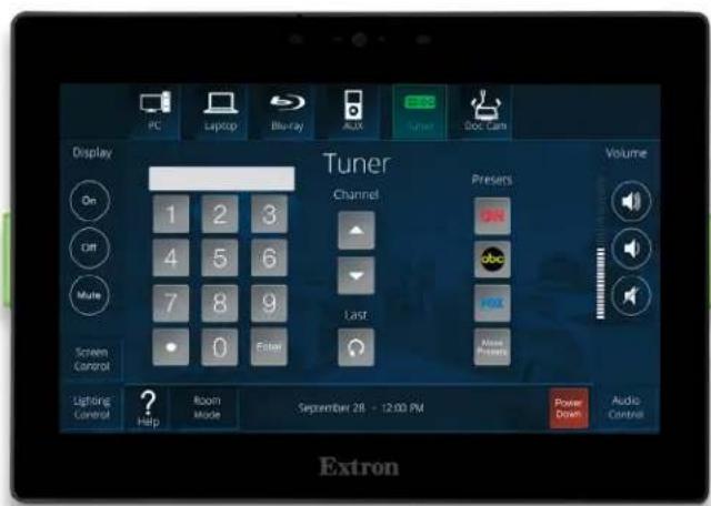
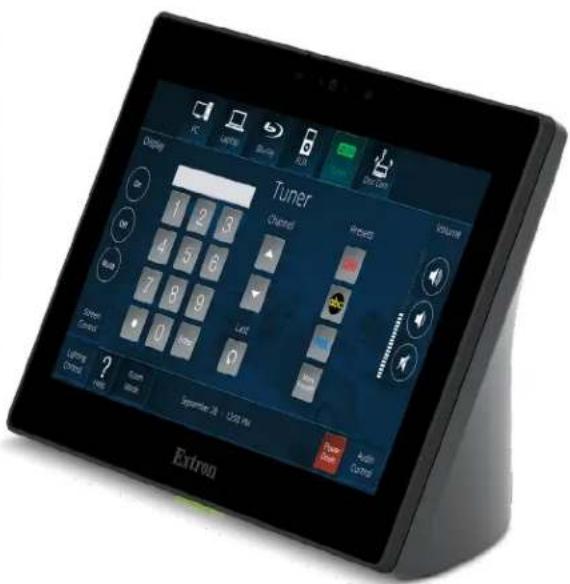
User Guide
TouchLink® Products
Safety Instructions
Safety Instructions • English

WARNING: This symbol, when used on the product, is intended to alert the user of the presence of uninsulated dangerous voltage within the product's enclosure that may present a risk of electric shock.
ATTENTION: This symbol, when used on the product, is intended to alert the user of important operating and maintenance (servicing) instructions in the literature provided with the equipment.
For information on safety guidelines, regulatory compliances, EMI/EMF compatibility, accessibility, and related topics, see the Extron Safety and Regulatory Compliance Guide, part number 68-290-01, on the Extron website, www.extron.com.
All trademarks mentioned in this guide are the properties of their respective owners.
The following registered trademarks (®), registered service marks (SM), and trademarks (TM) are the property of RGB Systems, Inc. or Extron (see the current list of trademarks on the Terms of Use page at www.extron.com):
| Registered Trademarks (®) |
| Extron, Cable Cubby, ControlScript, CrossPoint, DTP, eBUS, EDID Manager, EDID Minder, eLink, Flat Field, FlexOS, Glitch Free, Global Configurator, Global Scripter, GlobalViewer, Hideaway, HyperLane, IP Intercom, IP Link, Key Minder, LinkLicense, LockIt, MediaLink, MediaPort, NAV, NetPA, PlenumVault, PoleVault, PowerCage, PURE3, Quantum, ShareLink, Show Me, SoundField, SpeedMount, SpeedSwitch, StudioStation, System INTEGRATOR, TeamWork, TouchLink, V-Lock, VN-Matrix, VoiceLift, WallVault, WindoWall, XPA, XTP, XTP Systems, and ZipClip |
| Registered Service Mark ^(SM) : S3 Service Support Solutions |
| Trademarks ^(TM) |
| AAP, AFL (Accu-Rate Frame Lock), ADSP (Advanced Digital Sync Processing), AVEdge, CableCover, CDRS (Class D Ripple Suppression), Codec Connect, DDSP (Digital Display Sync Processing), DMI (Dynamic Motion Interpolation), Driver Configurator, DSP Configurator, DSVP (Digital Sync Validation Processing), EQIP, Everlast, FastBite, Flex55, FOX, FOXBOX, IP Intercom HelpDesk, MAAP, MicroDigital, Opti-Torque, PendantConnect, ProDSP, QS-FPC (QuickSwitch Front Panel Controller), Room Agent, Scope-Trigger, SIS, Simple Instruction Set, Skew-Free, SpeedNav, Triple-Action Switching, True4K, True8K, Vector ^TM 4K, WebShare, XTRA, and ZipCaddy |
FCC Class B Notice
NOTE: This device complies with part 15 of the FCC rules. Operation is subject to the following two conditions: (1) This device may not cause harmful interference, and (2) This device must accept any interference received, including interference that may cause undesired operation.
This equipment has been tested and found to comply with the limits for a Class B digital device, pursuant to part 15 of the FCC rules. These limits provide reasonable protection against harmful interference in a residential installation. This equipment generates, uses, and can radiate radio frequency energy and, if not installed and used in accordance with the instructions, may cause harmful interference to radio communications. There is no guarantee that interference will not occur. If this equipment does cause interference to radio or television reception, which can be determined by turning the equipment off and on, you are encouraged to try to correct the interference by one or more of the following measures:
- Reorient or relocate the receiving antenna.
- Increase the separation between the equipment and receiver.
- Connect the equipment into an outlet on a circuit different from that to which the receiver is connected.
- Consult the dealer or an experienced radio/TV technician for help.
In order to maintain compliance with FCC regulations, shielded cables must be used with this equipment. Operation with non-approved equipment or unshielded cables is likely to result in interference to radio and TV reception. The user is cautioned that changes and modifications made to the equipment without the approval of the manufacturer could void the user's authority to operate this equipment.
NOTE: For more information on safety guidelines, regulatory compliances, EMI/EMF compatibility, accessibility, and related topics, see the Extron Safety and Regulatory Compliance Guide on the Extron website.
Changes or modifications not expressly approved by the party responsible for compliance could void the user's authority to operate the equipment.
Battery Notice
This product contains a battery. Do not open the unit to replace the battery. If the battery needs replacing, return the entire unit to Extron (for the correct address, see the Extron Warranty section on the last page of this guide).
CAUTION: Risk of Explosion if Battery is replaced by an Incorrect Type. Dispose of Used Batteries According to the Instructions.
Class 1 Laser Product
Any service to this product must be carried out by Extron and its qualified service personnel.
CAUTION: Using controls, making adjustments, or performing procedures in a manner other than what is specified herein may result in hazardous radiation exposure.
NOTE: For more information on safety guidelines, regulatory compliances, EMI/EMF compatibility, accessibility, and related topics, see the “Extron Safety and Regulatory Compliance Guide” on the Extron website.
Complies with 21 CFR 1040.10 and 1040.11.
NOTE: The Safety Notices and Industry Canada Notices on this and the following pages refer to the TLP Pro 525M and TLP Pro 1025T models.
Antenna Warnings

WARNING: The radiated output power of the wireless device is far below the FCC radio frequency exposure limits. Nevertheless, the unit should be used in such a manner that the potential for human contact during normal operation is minimized. To avoid the possibility of exceeding the FCC radio frequency exposure limits, you should keep a distance of at least 20 cm between you (or any other person in the vicinity) and the antenna that is built into the unit.
NOTE: The wireless network device must be installed and used in strict accordance with Extron Electronic's instructions as described in the user documentation that comes with the product. Any other installation or use will violate FCC Part 15 regulations.
Compliance IC
Canada, Industry Canada (IC) Notices
CAN ICES-3 (B)/NMB-3(B)
This device complies with Industry Canada license-exempt RSS standard(s). Operation is subject to the following two conditions: (1) this device may not cause interference, and (2) this device must accept any interference, including interference that may cause undesired operation of the device.
This device complies with RSS247 of Industry Canada.
This Class B digital apparatus complies with Canadian ICES-003, Issue 4, and RSS-247, No 4.
To prevent radio interference to the licensed service, this device is intended to be operated indoors and away from windows to provide maximum shielding. Equipment (or its transmit antenna) that is installed outdoors is subject to licensing.
IC Antenna Statement
Under Industry Canada regulations, this radio transmitter may only operate using an antenna of a type and maximum (or lesser) gain approved for the transmitter by Industry Canada.
To reduce potential radio interference to other users, the antenna type and its gain should be so chosen that the equivalent isotropically radiated power (e.i.r.p.) is not more than that necessary for successful communication.
This radio transmitter has been approved by Industry Canada to operate with the antenna types listed below with the maximum permissible gain and required antenna impedance for each antenna type indicated.
Antenna types not included in this list, having a gain greater than the maximum gain indicated for that type, are strictly prohibited for use with this device.
Type: Chip
Maximum Peak Gain: 0.5 dBi
Impedance: 50 Ohm
Radio Frequency (RF) Exposure Information
This equipment complies with IC RSS-102 radiation exposure limits set forth for an uncontrolled environment. This equipment should be installed and operated with minimum distance 20 cm between the antenna and your body.
IC conformité
Canada, avis d'Industry Canada (IC)
CAN ICES-3 (B)/NMB-3(B)
Conventions Used in this Guide
Notifications
In this user guide, the following are used:

WARNING: Potential risk of severe injury or death.
CAUTION: Risk of minor personal injury.
NOTE: A note draws attention to important information.
Software Commands
Directory paths that do not have variables are written in the font shown here:
Reply from 208.132.180.48: bytes=32 times=2ms TTL=32
C:\Program Files\Extron
Variables are written in slanted form as shown here:
ping xxx.xxx.xxx.xxx -t
SOH R Data STX Command ETB ETX
Selectable items, such as menu names, menu options, buttons, tabs, and field names are written in the font shown here:
From the File menu, select New.
Click the OK button.
Specifications Availability
Product specifications are available on the Extron website, www.extron.com.
Extron Glossary of Terms
A glossary of terms is available at www.extron.com/technology/glossary.aspx.
Contents
Introduction....1
About This Guide....1
About the Touchpanels....2
Features 2
All Models....2
TLP Pro Series Touchpanels....3
TLP Pro 525M, TLP Pro 725M, and TLP Pro 1025M....3
TLP Pro 525T, TLP Pro 725T, and TLP Pro 1025T....3
TLS 525M, TLS 725M, and TLS 1025M....3
Application Diagrams 5
Requirements 6
Software 6
Hardware....6
Installation Overview....7
Panel Features....9
Front Panel Features....9
Rear Panel Features 11
TLP Pro 525T, TLP Pro 725T, and TLP Pro 1025T Base 13
Connecting Power....14
On-screen Menus 16
Setup Menu 16
Status....16
LinkLicenses 17
System Information 18
Network....19
Display 21
Audio 22
Advanced 23
Configuration Software....25
Configuration Software....25
TLS Touchpanels 25
TLP Pro Touchpanels....25
Installing Software 25
Using the Software 27
TLP Pro 525, 725, and 1025 Series Web Page 28
Updating the Firmware 30
Mounting 31
Mounting the TLP Pro x25M Series and TLS Series Touchpanels....31
Mounting to a Wall Box or Junction Box 32
Mounting to Drywall....34
Mounting the Touchpanels with Optional Kits 34
Mounting the TLP Pro 525T, 725T or 1025T 34
Desktop Mounting 34
LinkLicenses....35
What is an Extron LinkLicense? 35
How Customers Obtain a LinkLicense 35
Applying a LinkLicense....35
Reference Material....36
Best Practices for Cleaning Your Extron Products 36
Network Port Requirements and Licensed Third-Party Software Used by the Touchpanels....36
Digital I/O Port Cases 37
Connecting an Occupancy Sensor to the Digital I/O Port 37
Connecting a Two-position Switch to the Digital I/O Port 37
Reset Modes 38
Use Factory Firmware....38
Reset Network Settings....39
Full Factory Reset....39
Toggle DHCP Client 40
Secure Sockets Layer (SSL) Certificates 40
IEEE 802.1X Certificates....41
Certificate File Requirements....41
Private Key File Requirements....41
SNMP 42
Extron Warranty....43
Introduction
This section discusses the following topics:
- About This Guide
- About the Touchpanels
- Features
• Application Diagrams - Requirements
About This Guide
This guide describes the function, installation, and operation of the following Extron Touchlink Pro Touchpanels:
- TLP Pro 525M, TLP Pro 525M NC, TLP Pro 725M, TLP Pro 725M NC, TLP Pro 1025M, and TLP Pro 1025M NC — wall mountable touchpanels. For use in a high-security environment, the camera, Bluetooth, and microphone have been removed from the TLP Pro 525M NC, 725M NC, and 1025M NC models.
A range of mounting options are available for each model (see Mounting on page 31).
- TLS 525M, TLS 725M, and TLS 1025M — versions of the TLP Pro 525M, TLP Pro 725M, and TLP Pro 1025M adapted for use with Room Agent scheduling software. Other than Mounting, this guide does not apply to the TLS models. See the Room Agent User Guide or Room Agent Help File for more information.
- TLP Pro 525T, TLP Pro 525T NC, TLP Pro 725T, TLP Pro 725T NC, TLP Pro 1025T and TLP Pro 1025T NC — touchpanels with weighted bases that allow them to stand on any suitable flat surface. For use in a high-security environment, the camera, Bluetooth, and microphone have been removed from the TLP Pro 525T NC, 725T NC, and 1025T NC models.
Unless otherwise stated:
- The term "touchpanel" refers to all models.
- "Wall mountable" models refers to the TLP Pro 525M, TLP Pro 525M NC, TLP Pro 725M, TLP Pro 725M NC, TLP Pro 1025M, TLP Pro 1025M NC, and all three TLS models (TLS 525M, TLS 725M, and TLS 1025M).
- "Tabletop" models refers to the TLP Pro 525T, TLP Pro 525T NC, TLP Pro 725T, TLP Pro 725T NC, TLP Pro 1025T, and TLP Pro 1025T NC.
- The term "TLP Pro 725T" refers to the TLP Pro 725T and the TLP Pro 725T NC.
About the Touchpanels
These touchpanels are ideal for any AV application requiring small or medium-sized touchpanels with flexible mounting options and fully customizable interfaces.
For all TLP Pro models, the screen layout is designed with the Extron GUI Designer software. The functions are assigned to the screen objects with the Extron Global Configurator Plus and Professional software or ControlScript programming. The user can define the graphics and the functions associated with those graphics, providing versatility and adaptability to the configuration and control of an AV system.
The TLS 525M, TLS 725M, and TLS 1025M have the same physical appearance as the corresponding TLP Pro models but have different firmware. The TLS models can only be used with the room scheduling software (see the Room Agent Help File and Room Agent User Guide, which are available at www.extron.com).
Features
All Models
- LCD touchscreen — With 24-bit color depth and a vibrant edge-to-edge glass display.
• TLP Pro 525 Series and TLS 525M — 5-inch touchscreen with 800x480 (WVGA) resolution.
• TLP Pro 725 Series and TLS 725M — 7-inch touchscreen with 1024x600 (WSVGA) resolution.
• TLP Pro 1025 Series and TLS 1025M — 10.1-inch touchscreen with 1280x800 (WXGA) resolution.
- Gorilla ^® Glass screen is tough, scratch, and smudge-resistant — Corning ^® Gorilla Glass is stronger and more scratch-resistant than standard glass, while maintaining touch sensitivity, color saturation, and brightness.
- Faster, quad-core processing — Provides enhanced response and overall user experience.
- Power over Ethernet (PoE 802.3af, class 3) compliance — Allows the touchpanel to receive power and communication over a single Ethernet cable, eliminating the need for a local power supply (power injector sold separately).
- Optional Mounting Kits available.
- Mounting options for TLP Pro x25M series and TLS x25M series:
- Mount in a one-gang (TLP Pro 525M series and TLS 525M) or two-gang (TLP Pro 725M series, TLP Pro 1025M series, TLS 725M, and TLS 1025M) junction box or on a wall, lectern, or any flat surface, including glass, with the optional mounting kits (see www.extron.com).
- Mounting options for TLP Pro 525T Series, TLP Pro 725T Series, and TLP Pro 1025T series:
- Sit on a tabletop — Fixed 65 degree viewing angle provides optimum viewing comfort while seated or standing.
- Threaded holes in baseplate allow for secure mounting to a table.
-
Can be used with the optional SMA-2 Swivel Mount Adapter.
-
Manage, monitor, and control this device remotely using GVE — GlobalViewer Enterprise Resource Management software.
• Built-in speaker — Provides audible feedback from button presses.
• Light sensor — Adjusts screen brightness as the ambient room lighting changes.
• Automatic clock synchronization — Allows the touchpanel to display the accurate time and date.
• Energy-saving features — -
Adjustable sleep timer puts the touchpanel into sleep mode.
- Motion detector wakes the touchpanel.
• High speed USB 2.0 port — For future expansion.
TLP Pro Series Touchpanels
- Compatible with the full range of Extron IPL Pro and IPCP Pro control processors — Allows easy integration into existing systems.
- Transform your touchpanel into an all-in-one Pro xi Series control system using LinkLicense for TLP Control Processor and the TLCA 1 TouchLink Control Port Expansion Adapter — Supports up to four Ethernet-controllable devices using GC Plus and eight using GC Pro.
- System connection status indicator — The communication LED provides visual feedback if the touchpanel is not communicating with a control processor.
- Fully customizable using Extron control system software — GUI Designer combined with Global Configurator Plus, Global Configurator Professional, or ControlScript Deployment Utility.
- Manage, monitor, and control this device remotely using GVE - GlobalViewer Enterprise Resource Management software
• Supports the Extron Control App and Extron Control for Web. - TAA Compliant version available — Please inform your local Extron representative if your order requires compliance with TAA regulations.
TLP Pro 525M, TLP Pro 725M, and TLP Pro 1025M
• Digital input — Allows connections to a variety of devices, such as sensors and switches.
TLP Pro 525T, TLP Pro 725T, and TLP Pro 1025T
• Supports the optional SMA-2 Swivel Mount Adapter.
- Kensington lock support — Allows the touchpanel to be locked to a table or other flat surface.
- JITC Certified — Successfully completed interoperability and information assurance testing for use in government applications and other mission-critical environments (TLP Pro 725T and TLP Pro 1025T only).
- Highly reliable, energy-efficient external universal power supply (optional) — Provides worldwide power compatibility, with high demonstrated reliability and low power consumption for reduced operating costs. (TLP Pro 525T only).
TLS 525M, TLS 725M, and TLS 1025M
- Configurable red and green status lights indicate a room's availability or call status.
- All panel updates are conveniently handled through Room Agent.
- Make on-demand reservations from the touchpanel, computer, or any smartphone or tablet that connects to Microsoft® Exchange, Office 365™, Google Calendar™, 25Live®, EMS, NFS, and Ad Astra®.
- Room Agent software provides easy integration with Microsoft Exchange 2007, 2010, 2013, 2016, and 2019, as well as Office 365 for convenient scheduling right from Outlook.
- Supports two factor authentication (OAuth) required for Microsoft 365 — Refer to the Room Agent page for more software feature details.
- New Alternative Microsoft 365 authentication options — Administrators now have new Microsoft 365 authentication options using either Client Secret or Certificate Upload methods in Room Agent for extended TLS Panel - Server connection. These new workflows are supported for the TLS x25 devices and require MSGraph Application permissions in Microsoft Azure.
- No annual subscription or maintenance fees.
- PIN access for TLS panels configured with Microsoft 365, Exchange, Google, and 25Live, enabling users to reserve, book, check-in and extend a meeting via a PIN (English Only).
- Deploy a single touchpanel, or multiple touchpanels with similar settings very easily.
-
Ability to set/view room capacity via TLS panel — Users can now view the next upcoming meeting via the TLS panel user interface.
-
All communication between the touchpanel and calendar server is encrypted and secure.
- Digital input allows connection to an occupancy sensor, such as the Extron OCS 100.
- Room usage data provides insight into trends and activity — Each touchpanel includes a downloadable Scheduling Activity file that enables you to generate analytics on usage, activity patterns, and trends using data from across the enterprise or organization.
- Provides service account and impersonation support — TLS panels can be configured using a service account with Exchange or Office 365, simplifying administrative tasks.
- Ability to view meeting attendees for panels configured with Microsoft 365, Exchange, and Google.
- Meetings scheduled as private will by default have the meeting details hidden for meetings scheduled with Microsoft® Exchange, Office 365™, and Google Calendar™.
- Display up to 50 characters from the meeting body details for panels configured with Office 365™ and Microsoft Exchange — The TLS can display up to 50 characters from the meeting body for any selected custom dropdown.
- Meeting Subject Line accommodates up to 2 lines of text.
- Exchange auto-discovery streamlines system setup.
• Support for 802.1X certification on TLS panels, which can be managed via Extron Toolbelt software. - Two bright LED lights make it easy to see if a room is occupied or available even from down the hall.
• Supports 27 languages — For a complete list of supported languages, refer to Room Agent page. - Check-In button confirms attendance for the scheduled meeting and retains the reserved status of the room, even if the start of the meeting is delayed.
- Make meeting rooms available as soon as a scheduled meeting ends.
- Two color themes, custom loaded background images, and transparency controls provide personalized branding options.
- Customizable date and time formats with a preview showing how the UI will look on the touchpanel.
- Customizable room availability hours — Allows one to select the start and end times for the availability of a room.
• View details of the meetings scheduled for the day directly from the TLS panel. - Rear-facing light bars reflect off the mounting surface — Provides enhanced visibility of room status (TLS 725M and TLS 1025M only).
Application Diagrams
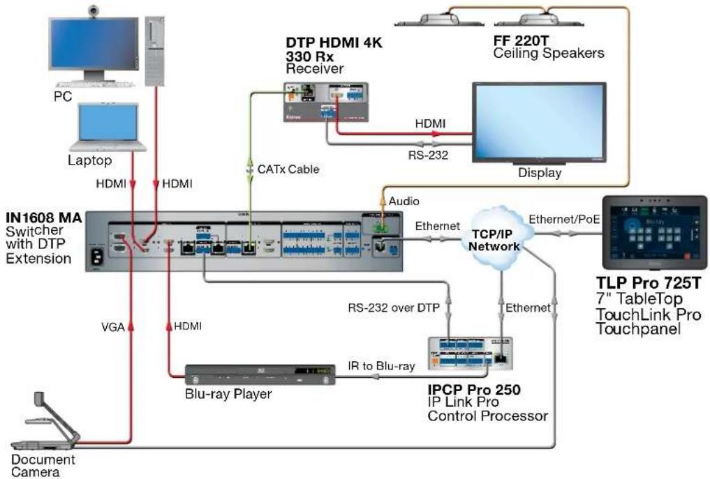
flowchart
graph TD
    PC["PC"] -->|HDMI| Switcher["IN1608 MA Switcher with DTP Extension"]
    Laptop["Laptop"] -->|HDMI| Switcher
    Switcher -->|VGA| Device["Document Camera"]
    Switcher -->|HDMI| Blu-ray_Player["Blu-ray Player"]
    Blu-ray Player -->|IR to Blu-ray| IPCPPro["IPC P Pro 250 IP Link Pro Control Processor"]
    IPCPPro -->|Ethernet/PoE| TCPIP["TCP/IP Network"]
    TCPIP -->|Ethernet| Display["Display"]
    CPU["DTP HDMI 4K 330 Rx Receiver"] -->|HDMI| Media["Media Hub"]
    Media -->|RS-232| TV["TV"]
    Media -->|CATx Cable| Cable["CATx Cable"]
    Cable -->|Audio| TCPIP
    TCPIP -->|Ethernet| Monitor["TLP Pro 725T 7" TableTop TouchLink Pro Touchpanel"]
    TV -->|Ethernet| Monitor
    Monitor -->|Ethernet| Media
    Media -->|DHMI| PC
    Media -->|DHMI| Laptop
    Media -->|DHMI| Switcher
    Media -->|DHMI| Video
    Media -->|DHMI| Audio
    Media -->|DHMI| Video
    Media -->|DHMI| Video
    Media -->|DHMI| Video
    Media -->|DHMI| Video
    Media -->|DHMI| Video
    Media -->|DHMI| Video
    Media -->|DHMI| Video
    Media -->|DHMI| Video
    Media -->|DHMI| Video
    Media -->|DHMI| Video
    Media -->|DHMI| Video
    Media -->|DHMI| Video

    subgraph Legend
    PC
    L
    L
    Switcher
    Switcher
    Video
    Audio
    Radio
    Bluetooth
    Radio
    Bluetooth
    Radio
    Bluetooth
    Radio
    Bluetooth
    Radio
    Bluetooth
    Radio
    Bluetooth
    Radio
    Bluetooth
    Radio
    Bluetooth
    Radio
    Bluetooth
    Radio
    Bluetooth
    Radio
    Bluetooth
    Radio
    Bluetooth
Figure 1. Application Diagram for TLP Pro 725T
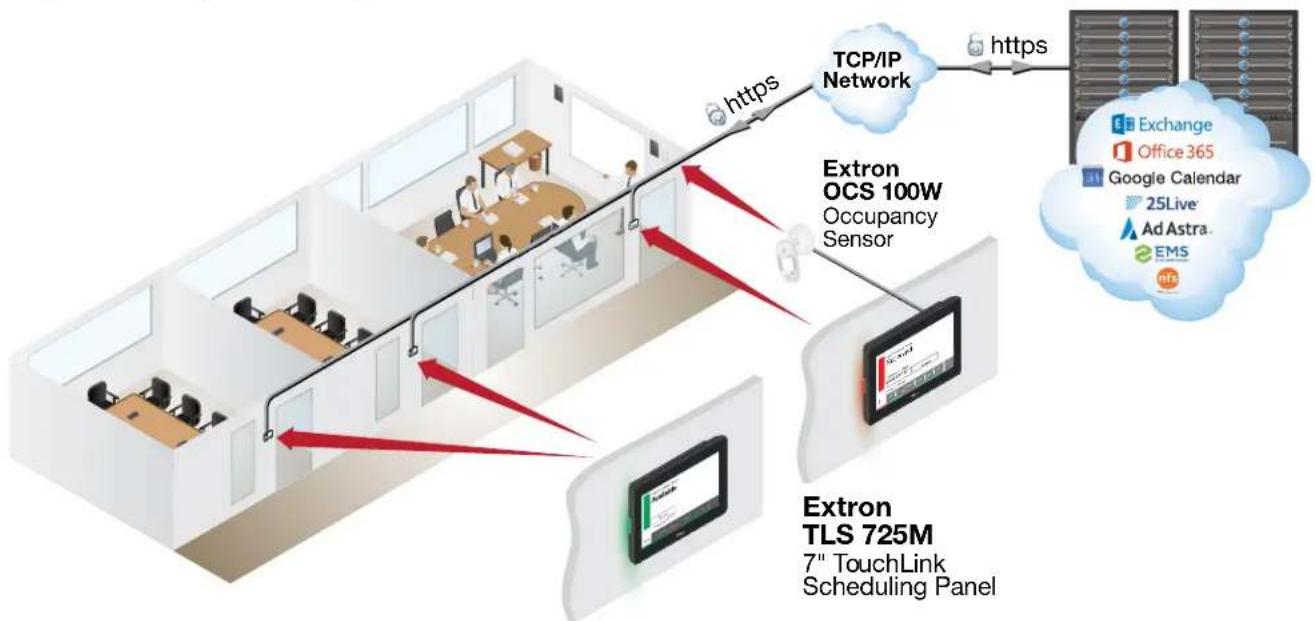
flowchart
graph TD
    A["Extron TLS 725M\n7" TouchLink\nScheduling Panel"] --> B["Extron OCS 100W\nOccupancy Sensor"]
    B --> C["TCP/IP Network"]
    C --> D["Exchange"]
    C --> E["Office 365"]
    C --> F["Google Calendar"]
    C --> G["25Live"]
    C --> H["Ad Astra."]
    C --> I["EMS"]
Figure 2. Application Diagram for TLS 725M
Requirements
Software
For a complete list of the requirements for running GUI Designer, Global Configurator Plus and Professional, ControlScript Deployment Utility, Toolbelt, and Room Agent see the Extron web page (www.extron.com) for that software.
NOTE: These touchpanels are not compatible with Global Configurator 3 or GUI Configurator.
Hardware
An Extron IP Link Pro control interface must also be connected to the same network domain as the TLP Pro TouchLink panel. See www.extron.com for a list of suitable controller processor.
NOTE: These TLP Pro touchpanels are not compatible with Extron IP Link (non-Pro) control processors.
The TLS models do not require a control processor.
Installation Overview
This section provides an overview of the installation process. Follow the links for a more detailed explanation of each step.
-
Before starting to install the touchpanels, download and install the latest versions of the following software:
-
GUI Designer (TLP Pro models only) — For designing layouts for Extron TouchLink Pro touchpanels and third party touch interfaces. (TLP Pro models only)
- Global Configurator Plus and Professional (TLP Pro models only) — For setting up and configuring the control processor and touchpanel.
- ControlScript Deployment Utility (TLP Pro models only) — Provide integrated development environments for Extron control systems programming.
See Configuration Software on page 25. - Toolbelt (TLP Pro and TLS models) — Provides device discovery, device information, firmware updates, and configuration of network settings, system utilities, and user management.
• Room Agent (TLS models only) — For setting up and configuring the Room Scheduling System.
NOTE: The TLS models do not need to be configured or programmed. Other than setting network addresses (see On-screen Menus on page 16), they are ready to use, as shipped.
- Before starting to install the TLP Pro or TLS models, obtain the following network information from your network administrator:
• Dynamic Host Configuration Protocol (DHCP) status (on or off). If DHCP is off, you also require:
- IP address • Subnet mask • Gateway
- User name — This can be either admin or user.
- Password — The factory configured passwords for all accounts on this device have been set to the device serial number. Passwords can be changed during configuration. Passwords are case sensitive.
- User name — This can be either admin or user. - Password — The factory configured passwords for all accounts on this device have been set to the device serial number. Passwords can be changed during configuration. Passwords are case sensitive.
NOTE: If the device is reset to default settings, the password is the default password configuration. The default password is extron (for either admin or user accounts).
- MAC address — Make a note of the touchpanel MAC address, which can be found on the rear panel label (TLP Pro 525M, 725M, or 1025M) or a label on the base (TLP Pro 525T, 725T, or 1025T).
NOTE: This information is not required for the TLS models.
- SSL security certificates and IEEE 802.1X authentication — Extron touchpanels come with a factory-installed Secure Sockets Layer (SSL) security certificate. IEEE 802.1X authentication is also supported once enabled. See Secure Sockets Layer (SSL) Certificates on page 40 or see IEEE 802.1X Certificates on page 41 for more information.
3. Mount and cable the units:
ATTENTION:
- If you use the setup menu to configure the TLP Pro 525M, 725M, or 1025M for network communication (see step 4, below), configure the touchpanel before mounting as you will need access to the rear panel Menu button.
-
The TLS models do not use the setup menu.
-
Connect cables to the touchpanels (see TLP Pro 525T, TLP Pro 725T, and TLP Pro 1025T Base on page 13 or Rear Panel Features on page 11).
-
Connect the power cords and power on all devices (see figure 4, F, on page 11 or figure 5, F, on page 13).
-
Set up the touchpanels for network communication:
-
Connect the PC that you are using for setup, the Extron control processor (not required for TLS models), and the touchpanel to the same Ethernet subnetwork.
- For TLP models, use the On-screen Menus on page 16 or Toolbelt to set the DHCP status and, if required, the IP address, subnet mask, gateway, and related settings for the touchpanel.
-
For TLS models, use the Network settings of Room Agent to set the DHCP status and, if required, the IP address, subnet mask, gateway, and related settings for the touchpanel.
-
Configure or program the Touchpanels
-
For TLS touchpanels, the Room Agent Help File provides step-by-step instructions and detailed information.
- For TLP Pro touchpanels, the GUI Designer Help File, the Global Configurator Plus and Professional Help File, the ControlScript Deployment Utility Help File, and the Toolbelt Help File provide step-by-step instructions and detailed information.
- The Global Configurator Help File also includes an introduction to that software and sections on how to start a project and configuration.
- ControlScript Deployment Utility provides an Extron-exclusive Python library, including Extron ControlScript Extension for VS Code. See the ControlScript Deployment Utility Help File for more information.
NOTE: Frequently touched devices, such as touchscreens, require regular cleaning to ensure their surfaces remain sanitary. Plastic surfaces and cosmetic finishes can be damaged by long term exposure to chemicals. For Best Practices for Cleaning Your Extron Products on page 36.
Panel Features
This section describes the TLP Pro x25 series and TLS series touchpanels:
- Front Panel Features
- Rear Panel Features
• TLP Pro 525T, TLP Pro 725T, and TLP Pro 1025T Base - Connecting Power
Front Panel Features
Figure 3 shows the TLP Pro 725M (left) and TLP Pro 725T (right) front panels. The front panels for all models, including TLS touchpanels have the same features and are very similar, apart from size.
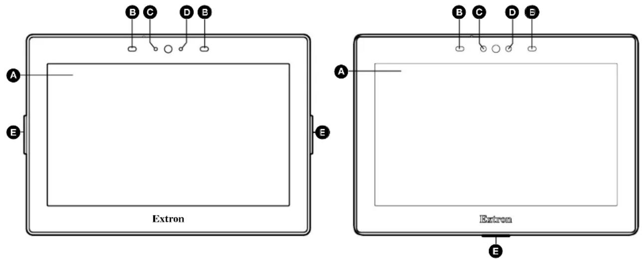
A LCD touchscreen
© Communication LED
E Front status light
B Motion sensor
D Light sensor
Figure 3. TLP Pro 725M (left) and TLP Pro 725T (right) Front Panels
A LCD touchscreen — Made with tough, scratch-resistant touchscreen.
• TLP Pro 525 Series and TLS 525 — 5-inch touchscreen with 800x480 (WVGA) resolution
• TLP Pro 725 Series and TLS 725 — 7-inch touchscreen with 1024x600 (WSVGA) resolution
• TLP Pro 1025 Series and TLS 1025 — 10.1-inch touchscreen with 1280x800 (WXGA) resolution
B Motion sensor (two) — The sensor detects motion between 3 to 5 feet (0.9 to 1.5 meters) from the TLP, and at least 15^ from the center axis.
When both Sleep Mode and Wake on Motion have been enabled (see Display on page 21):
- When no motion has been detected for a user-defined period of time, the touchpanel enters sleep mode.
- When motion is detected by the sensor, the screen display is restored and active.
C Communication LED — (see figure 3 on page 9). Shows the configuration and connection status of the touchpanel:
- Unlit during normal operation (the touchpanel is configured and connected to an IP Link Pro control processor).
- Blinks if the touchpanel has been configured but is not connected to an IP Link Pro control processor.
- Lights steadily if the touchpanel has not been configured.
The indicator can be enabled and disabled, using the On-screen Menus on page 16).
Light sensor — Monitors ambient light level and adjusts screen brightness, based on the settings configured using the Setup Menu.
E Front status light — The TLS Series and TLP Pro 525M, 725M, and 1025M have two LEDs (one on each side). The TLP Pro 525T, 725T, and 1025T have a single LED (in the center of the bottom edge).
- For the TLS series touchpanels, the lights remain lit steadily to indicate whether the room is occupied (red) or available (green).
- For the TLP Pro touchpanels, the lights can blink or remain lit steadily and they can light red or green. The lights can be configured (using Global Configurator) or programmed (using ControlScript programming) to provide feedback information about the system using these variables. Different combinations, for example a red LED lit steadily or a green LED that is blinking, can provide indications about the system.
For information about setting up these LEDs, see the Global Configurator Help File or the ControlScript Deployment Utility Help File.
Rear Panel Features
Figure 4 shows the rear panels of the TLP Pro 525M (top left), TLP Pro 725M (bottom left), TLP Pro 1025M (top right) and TLP Pro 725T (bottom right). The rear panels of the TLS series are similar to the TLP Pro x25M models. The rear panels of the TLP Pro 525T and TLP Pro 1025T are similar to the TLP Pro 725T. The rear panels of the NC models are similar to the corresponding "Non-NC" models.
Many of the features shown on the TLP Pro 525M, 725M, or 1025M rear panels are found on the TLP Pro 525T, TLP Pro 725T, and TLP Pro 1025T Base (see page 13).
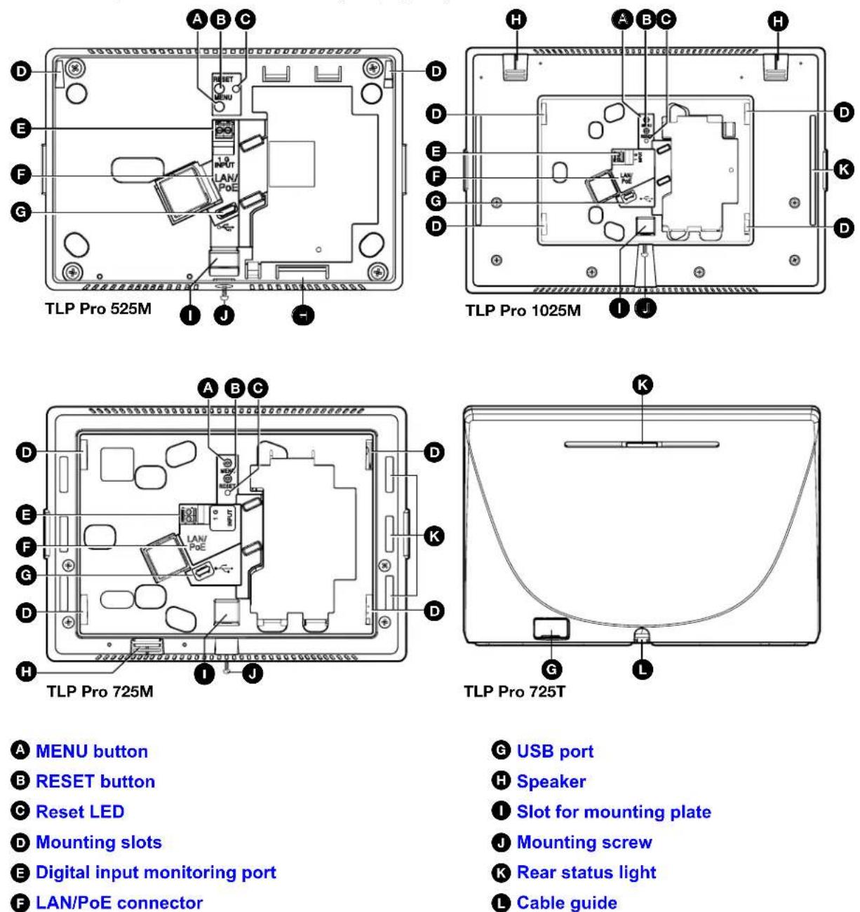
A MENU button
B RESET button
© Reset LED
D Mounting slots
E Digital input monitoring port
F LAN/PoE connector
G USB port
H Speaker
① Slot for mounting plate
J Mounting screw
K Rear status light
L Cable guide
Figure 4. TLP Pro 525M (top left), 725M (bottom left), 1025M (top right) and 725T (bottom right) Rear Panels
A MENU button (TLS Series and TLP Pro x25M only) — (figure 4 on page 11) Activates the On-screen Menus (see page 16).
B RESET button (TLS Series and TLP Pro x25M only) — Pressing the RESET button allows the unit to be reset in any of three different modes and can also be used to toggle between enabling and disabling the DHCP client (see Reset Modes on page 38).
C Reset LED (TLS Series and TLP Pro x25M only) — Provides feedback about the reset status when the RESET button is pressed (see Reset Modes).
Mounting slots (TLS Series and TLP Pro x25M only) — The TLP Pro 725M and 1025M have four, one in each corner. The TLP Pro 525M has two, one in each top corner (see Mounting the TLP Pro x25M Series and TLS Series Touchpanels on page 31).
Digital input monitoring port (TLS Series and TLP Pro x25M only) — This two-pole captive screw port (1 = signal and G = ground) monitors digital input with or without a +5 VDC pull-up.
The table below provides information about the ports:
| Digital Input, Pullup Disabled | |
| Logic State Notes | |
| Logic Low Voltage below 2.0 VDC | |
| Logic High Voltage above 2.8 VDC | |
| Digital Input, Pullup Enabled | |
| Logic State Notes | |
| Logic Low Externally shorted to ground | |
| Logic High Open, +5V from pull-up resistor |
See Digital I/O Port Cases on page 37, for examples of how these ports function.
F LAN/PoE connector (TLS Series and TLP Pro x25M only) — These touchpanels must be powered by Power over Ethernet (PoE; see Connecting Power on page 14).
ATTENTION:
NOTE: The touchpanels ship without a power injector. The power injector must be purchased separately.
An Extron IPL Pro control processor must also be connected to the same network domain as the TouchLink Pro touchpanel (see www.extron.com for a list of compatible models).
The network port has two LEDs. The green LED lights steadily to indicate that the touchpanel is connected correctly to a network. The yellow LED blinks to indicate that data is being passed to or from the touchpanel.
USB port — Compatible with USB 2.0. The TLP Pro 525T, TLP Pro 725T, and TLP Pro 1025T have a plastic cover that must be removed for access to the USB port.
H Speaker (TLS Series and TLP Pro x25M only) — Provides audible feedback for the user. The TLP Pro 525M and 725M have a single speaker. The TLP Pro 1025M has two (dual mono) speakers.
Slot for mounting plate (TLS Series and TLP Pro x25M only) — The tongue at the bottom of the mounting plate fits into this slot, for wall mounting (Mounting the TLP Pro x25M Series and TLS Series Touchpanels).
Mounting screw (TLS Series and TLP Pro x25M only) — Tightens against the tongue of the mounting plate to secure the touchpanel (see Mounting the TLP Pro x25M Series and TLS Series Touchpanels).
K Rear status light — The TLS 525M and TLP Pro 525M do not have any rear panel status lights. The TLS 725M and TLP Pro 725M has six LEDs (three on each side of the rear panel). The TLS 1025M and TLP Pro 1025M have a single LED strip on each side. The TLP Pro 525T, TLP Pro 725T, and TLP Pro 1025T have a single LED (top center of the rear panel).
The lights can blink or remain steadily lit and they can light red or green. The lights can be configured (using Global Configurator) or programmed (using ControlScript Deployment Utility) to provide feedback information about the system using these variables. Different combinations, for example a red LED lit steadily or a green LED that is blinking, can provide indications about the system. For information about setting up these LEDs, see the Global Configurator Help File or the ControlScript Deployment Utility Help File.
The rear panel status lights of the TLP Pro 725M and the TLP Pro 1025M can be disabled, using the On-screen Menus (see page 16).
L Cable guide (TLP Pro 525T, 725T, and 1025T only) — The Ethernet cable is inserted through this hole at the back of the base (also see figure 5, C, below).
TLP Pro 525T, TLP Pro 725T, and TLP Pro 1025T Base
Figure 5 shows the TLP Pro 725T (top) and the TLP Pro 525T base (bottom). TLP Pro 1025T base is similar to the TLP Pro 725T base.
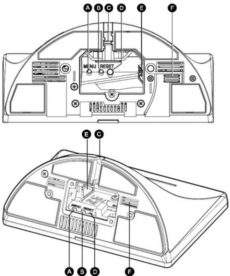
A MENU button
B RESET button
Cable guide
D RESET LED
E LAN/PoE connector
F Speaker
Figure 5. TLP Pro 725T (top) and TLP Pro 525T (bottom) Base
A MENU button — Activates the On-screen Menus (see page 16).
B RESET button — Pressing the RESET button allows the unit to be reset in any of three different modes and can also be used to toggle between enabling and disabling the DHCP client (see Reset Modes on page 38).
Cable guide (see figure 5 on page 13) — The Ethernet cable is inserted through this hole at the back of the base (see LAN/PoE connector on page 14).
RESET LED — Provides feedback about the reset status when the user presses the RESET button (see Reset Modes on page 38).
E LAN/PoE connector — These touchpanels must be powered by Power over Ethernet (PoE; see “Connecting Power”, below).
ATTENTION:
NOTE: The touchpanels ship without a power injector. The power injector must be purchased separately.
An Extron IPL Pro control processor must also be connected to the same network domain as the TouchLink Pro touchpanel (see the www.extron.com for a list of suggested models).
The network port has two LEDs. The green LED lights steadily to indicate that the touchpanel is connected correctly to a network. The yellow LED blinks to indicate that data is being passed to or from the touchpanel.
F Speaker — A single speaker provides audible feedback for the user.
Connecting Power
These touchpanels must be powered by Power over Ethernet (PoE). Users must provide their own PoE power injector. Figure 6 shows the Extron XTP PI 100. Your power injector may look different.
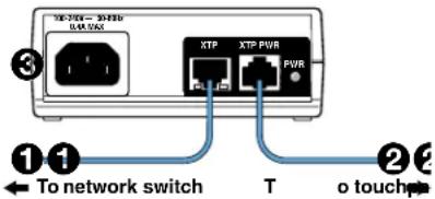
Figure 6. XTP PI 100 Power Injector
- Connect a straight-through Ethernet cable from the power injector to a switch or router (figure 6, ①). This cable carries network information from the switch or router to the power supply.
- Connect a second straight-through cable (②) from the power injector to the touchpanel. This cable carries the network information and 48 VDC from the power injector to the touchpanel.
- Connect the IEC power cord to a convenient 100 VAC to 240 VAC, 50-60 Hz power source (③).
Alternatively, connect the touchpanel to a PoE switch.
On-screen menus allow initial configuration of the touchpanels. The figures in this section show screens for the TLP Pro 525M. Unless stated otherwise, the screens for the other touchpanels are very similar.
Setup Menu
To open the setup menu, use a screw driver with a fine blade to press the MENU button. The MENU button is located on the rear panel of the TLP Pro 525M, 725M, or 1025M (see figure 4, A, on page 11) or on the base of the TLP Pro 525T, 725T, or 1025T (see figure 5, A, on page 13).
The menus open at the Status screen. There are seven different panels:
• Status (see below)
• Display (see page 21)
• LinkLicenses (see page 17)
• Audio (see page 22)
• System Information (see page 18)
• Advanced (see page 23)
• Network (see page 19)
Status, Network, Display, Audio, and Advanced screens can be selected by pressing the appropriate button in the navigation panel at the top of the screen. The button for the selected screen is yellow. The buttons for the remaining screens are black.
LinkLicenses and System Information are available only from the Status screen.
Press the red Exit button in the top right corner of the screen button to apply and save any changes and close the menu screens.
Status
Press the Status button in the navigation panel at the top of any screen to open the Status screen.
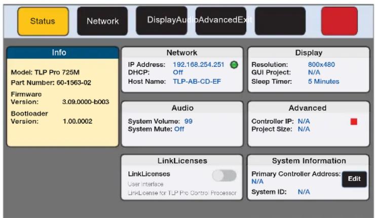
Figure 7. Status Screen
The Status screen is mostly read-only and provides basic information about the touchpanel. Each of the other six panels shows a summary of the information on the other screens.
Pressing the Network, Display, Audio, and Advanced panels opens the corresponding screen in exactly the same way as pressing the buttons in the top navigation panel. Features in the LinkLicenses (see page 17) and System Information (see page 18) panels can only be accessed from the Status screen.
A green bubble in the Network panel lights when there is a network connection or a red square appears if there is no connection (see figure 7). The green bubble in the Advanced panel lights when a control processor is connected or a red square appears if none is connected.
LinkLicenses
For information about LinkLicenses, see LinkLicenses on page 35.
Enable LinkLicenses
The Enable LinkLicenses feature is available from the Status (see page 16). When the LinkLicense is enabled, the touchpanel is a control processor.
- To enable LinkLicences, set the LinkLicense switch to on by moving the toggle switch in the System Information pane to the right (see image to the right).

NOTE: A LinkLicense must be applied to the touchpanel for the toggle switch to be active.
The Enable LinkLicenses dialog box opens.

Enable LinkLicenses
Enabling LinkLicenses will remove all user loaded project files and reboot the device.
Enable LinkLicenses Camel
Figure 8. Enable LinkLicenses
- Click Enable LinkLicenses.
The dialog text changes to Waiting to Reboot.
The screen goes blank as the touchpanel reboots.
NOTES:
- All projects that were on the touchpanel have been removed and need to be reloaded.
- When the LinkLicense for the unit is enabled, the device name changes to Model Name with LinkLicense and the part number for the device changes to 60-xxxx-02C (see figure 7 on page 16).
Disable LinkLicenses
The Disable LinkLicenses feature is available from the Status screen.
- To disable LinkLicences, set the LinkLicense switch to off by moving the toggle switch in the System Information pane to the left (see image to the right). A dialog box opens.

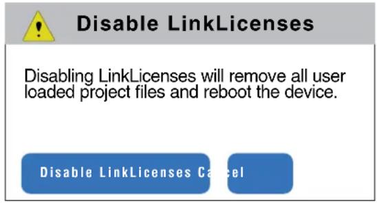
Figure 9. Disable LinkLicenses
- Click Disable LinkLicenses.
The dialog text changes to Waiting to Reboot.
The screen goes blank as the touchpanel reboots.
NOTES:
- All projects that were on the touchpanel have been removed and need to be reloaded.
- When the LinkLicense for the unit is enabled, the device name changes to Model Name and the part number for the device changes to 60-xxxx-02 (see figure 7 on page 16).
System Information
NOTE: TLS models do not need to be connected to a control processor. This section applies only to TLP Pro models.
With a LinkLicense, the TLP Pro device is a control processor. Without a LinkLicense, it is a touchpanel and must be connected to primary control processor. The process of connecting the touchpanel to a control processor is called pairing and is carried out from the System Info section of the Status tab without requiring another build and upload of the GCP file.
NOTE: When the touchpanel is in LinkLicense mode, it is the controller and cannot be paired with another control processor. In LinkLicense mode, the Primary Controller Address and System ID information are not shown.
To pair the touchpanel with a control processor, follow these instructions:
- Click Edit in the System Information panel of the Status page (see figure 7). The System ID dialog box opens.
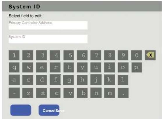
Figure 10. System ID Dialog Box
-
Enter the Primary Controller Address.
-
Enter the System ID. This is a four digit number generated by ControlScript Deployment Utility or Global Configurator Plus and Professional and needed to link the touchpanel to a control processor. For more information, see the ControlScript Deployment Utility Help File or Global Configurator Plus and Professional Help File.
The dialog box closes and the Primary Controller Address and the System ID are displayed in the System Information pane.
Network
Verify with your network administrator whether the IP address for the touchpanel is assigned by Dynamic Host Configuration Protocol (DHCP) or set manually. If they are set manually, you need to obtain an IP address, a subnet mask, a gateway address, and a Domain Name Server (DNS) from the network administrator.
Press the Network button in the navigation panel at the top of the screen to open the Network screen.
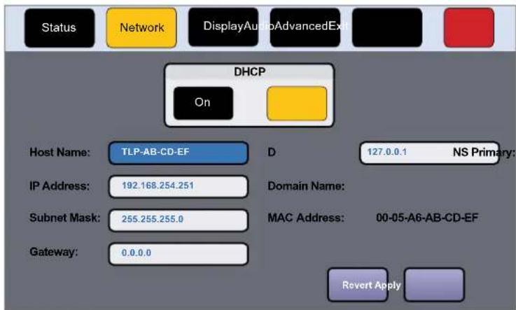
Figure 11. Network Screen
-
If IP addresses are assigned by DHCP, press 0n. If IP addresses are assigned manually, press Off. When DHCP is 0n, the Host Name can be edited. The addresses are grayed out and cannot be edited because they are set by the DHCP server (see figure 11). When DHCP is Off, the Host Name is grayed out and cannot be edited. All addresses can be edited.
-
If DHCP is on, press the Host Name button to edit the Host Name. The Host Name dialog box opens:
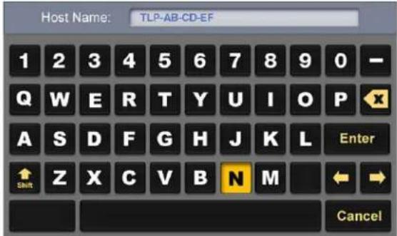
Figure 12. Alphanumeric Keypad
- Use the keypad to enter a new name, which appears in the Host Name text box.
If DHCP is disabled, set the unit IP address, subnet mask, gateway address, and DNS server address.
- Press the button for the address to be edited (see figure 11 on page 19). A screen opens, showing the address and a numerical keypad.
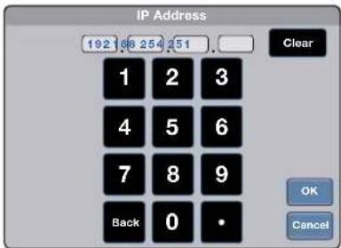
Figure 13. Numeric Pad for Setting IP Addresses
- Select an octet and enter the 3-digit value (leading zeroes in the octet are ignored).
NOTES:
• Octets can have any value between 0 and 255.
- If you attempt to enter an invalid number, for example 892, you are able to enter the 89 but the 2 cannot be entered.
- When a valid 3-digit value is entered, the next octet is automatically selected.
- Press OK to save the changes and return to the Network screen or press Cancel to return to the Network screen without saving the changes.
If you have changed any of the values in the Network screen, the background color of the button changes to blue. Press Apply to apply the new values or press Revert to return to the previous values without saving the changes. The address button returns to gray (see figure 11 on page 19).
If you have not made any changes, the Apply and Revert buttons are grayed out.
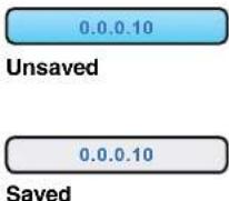
Figure 14. IP Address, unsaved (top) and saved (bottom).
Display
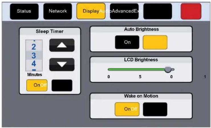
Press the Display button in the navigation panel at the top of the screen to open the Display screen.
00
Figure 15. Display Screen
The Display screen allows you to set the Sleep Timer, Auto Brightness, LCD Brightness, and Wake on Motion.
• Sleep Timer — Toggle between On and Off.
- If the Sleep Timer is on, after a period of inactivity, the screen goes dark to save power (Sleep mode). Use the up and down arrows to set how long the period of inactivity should be. The value can be between 1 and 120 minutes.
• If the Sleep Timer is off, the panel does not enter sleep mode.
• Auto Brightness — Toggle between On and Off.
- If Auto Brightness is on, the light sensor (see figure 3, D, on page 9) monitors the amount of ambient light detected and automatically provides a suitable amount of screen backlighting for the situation.
• If Auto Brightness is off, the screen brightness is not affected by changes in the ambient light.
• LCD Brightness — Use the slider control to adjust the screen brightness between 0 and 100.
- Wake on Motion — Toggle between On and Off. For this to work, the touchpanel must be in sleep mode.
- If Wake on Motion is on, and the touchpanel is in sleep mode, any motion detected by the motion sensor (B) wakes the panel from sleep mode. The screen lights and all buttons become functional.
- If Wake on Motion is off, the panel does not wake in response to nearby motion and the touchpanel can be activated by pressing anywhere on the screen.
Configuring the Motion Sensor
The Motion Sensor (B) detects motion between three to five feet from the touchpanel, and at least 15^ from the center axis.
- If the Sleep Timer has been set and no motion has been detected for a user-defined period of time, the touchpanel enters sleep mode.
• If the Sleep Timer has not been set, the touchpanel does not enter sleep mode. - If Wake on Motion has been set and motion is detected by the sensor while the screen is in sleep mode, the screen display is restored and active.
- If Wake on Motion has not been set and the screen is in sleep mode, touch the screen to restore it to an active state.
Audio
Press the Audio button in the navigation panel at the top of the screen to open the Audio screen.
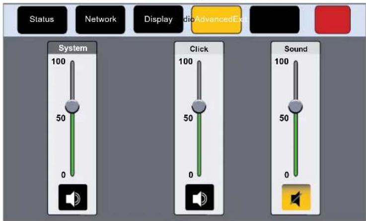
Figure 16. Audio Screen
On the Audio screen, use the slider controls to adjust the System, Click, and Sound volume settings.
- System — Sets the maximum volume for all the other sound volume settings. For example, if the System volume is set to 80 (80 percent of maximum), when the sound volume is set to 90, it is equivalent to 90 percent of 80, which is 72 percent of maximum.
- Click — Sets the volume for audible feedback that accompanies events such as a screen button being pressed.
• Sound — Sets the volume of audio from any audio file playback. - Speaker icon — Click on the Speaker icon at the bottom of each panel to toggle between audio on and audio mute. The sound audio is muted in figure 16, above.
Advanced
Press the Advanced button in the navigation panel at the top of the screen to open the Advanced screen. The TLP Pro 725M and TLP Pro 1025M series wall mount models have the option to Enable or Disable the rear panel status lights (see figure 17). This option is not available for the TLP Pro 525M, TLP Pro 525T, TLP Pro 725T, or TLP Pro 1025T series touchpanels (see figure 18).
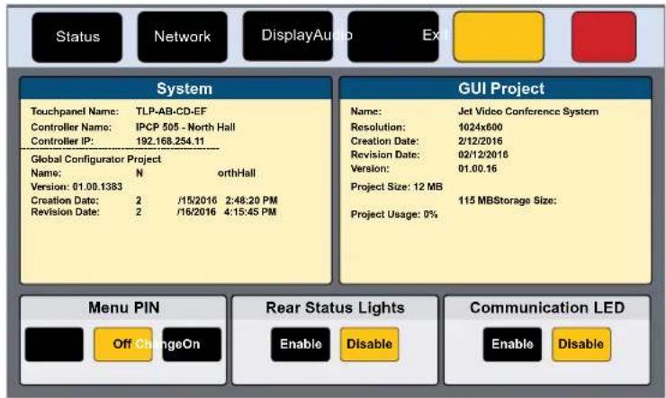
Figure 17. Advanced Screen (TLP Pro 725M)
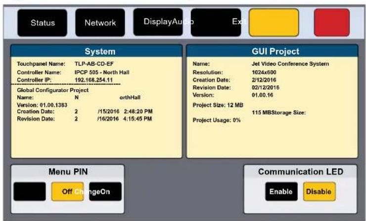
Figure 18. Advanced Screen (All Other Touchpanels)
System and GUI Project Panels
These panels are read only, providing information about the system, the Global Configurator Project, and the GUI Designer Project.
Menu PIN
The PIN setup options allow you to enable, disable, or change the setup menu PIN. The PIN is a 4-digit number. Each digit can have any value from 0-9.
- Click On to enable the use of a PIN. Click Off to disable the use of a PIN. Click Change to edit an existing PIN. (see figure 17 or figure 18 on page 23).
If no PIN has been set, clicking On or Change opens the PIN dialog.
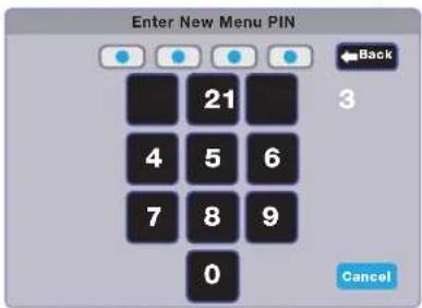
Figure 19. Numeric Keypad for Setting PIN
- Press a number on the keypad. A blue circle appears in the first box.
- Select the other three digits for the PINs. The fourth circle appears momentarily and then the screen changes to Confirm New Menu Pin.
- Enter the PIN a second time. When the PIN entered on the second occasion matches the PIN entered on the first occasion, the PIN is set and the dialog closes.
Rear Status Lights
These lights can be switched on or off by pressing the Enable or Disable button (see figure 17 on page 23 [TLP Pro 725M and TLP Pro 1025M series only]).
Communication LED
The LED can be switched on or off by pressing the Enable or Disable button (see figure 17 or figure 18 on page 23).
Configuration Software
This section of the user guide provides information about:
- Configuration Software
- Installing Software
• Using the Software
• TLP Pro 525, 725, and 1025 Series Web Page - Updating the Firmware
Configuration Software
TLS Touchpanels
Room Agent — Used to configure TLS touchpanels and connect to calendar servers. For further information, see the Room Agent Help File.
Extron Toolbelt — provides device discovery, device information, installation of 802.1x certificates, firmware updates, and configuration of network settings, system utilities (testing connection to a proxy server), and user management for TouchLink Pro devices. For further information, see the Toolbelt Help File.
TLP Pro Touchpanels
Use Toolbelt to provide device information, firmware updates, and configuration of network settings, system utilities (reset, reboot), and user management (username and password) for TouchLink Pro devices.
GUI Designer, Global Configurator Plus and Professional, and ControlScript Deployment Utility are used to design the touchpanel screen and assign functions to the screen elements. For further information, see the help file for the appropriate software.
Installing Software
The TLS 525, 725, and 1025 touchpanels are compatible with Room Agent and Toolbelt.
The TLP Pro 525, 725, and 1025 series touchpanels are compatible with GUI Designer, Global Configurator Plus and Professional, ControlScript Deployment Utility, and Toolbelt.
All five software products can be downloaded from www.extron.com.
NOTE: Ensure you are downloading the correct software. These touchpanels are not compatible with Global Configurator 3 or GUI Configurator.
- On the Extron home page, select the Downloads tab (see figure 20, ①).
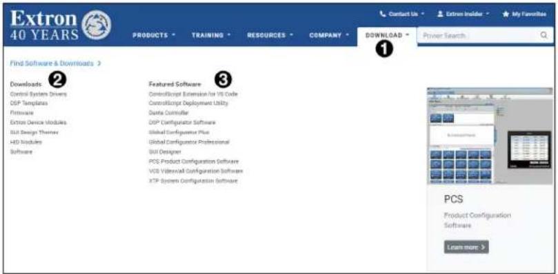
Figure 20. Downloads Tab
- Carry out one of these options:
- If the software of interest is listed in the Featured Software list (③), click on it directly. This takes you directly to the product web page (see figure 21).
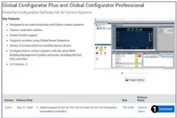
Figure 21. Software Product Page
• Otherwise, click Software in the Downloads list (see figure 20, ②).
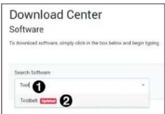
Figure 22. Software Downloads from the Extron Website
a. Start typing the name of the software in the Search Software text box (see figure 22, ①).
The name of the software appears in a drop-down list (②).
b. Click the Software name.
Information about the software appears under the Search Software text box (see figure 23).
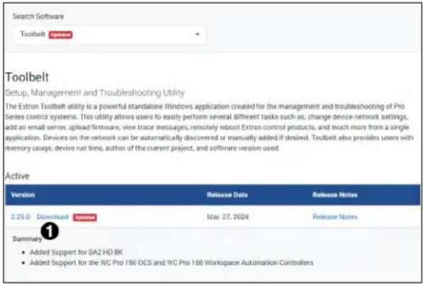
Figure 23. Software Product Information
- Click Download whether you are on the Software Product page (see figure 21, ①, on page 26) or the Software Search page (see figure 23, ①).
An executable file (.exe) is placed in your default Downloads folder.
NOTES:
- You may need an Extron Insider account to run some of these software programs. To obtain one, contact the Extron Sales Department.
-
Ensure you are downloading the correct software. TLP Pro touchpanels are not compatible with Global Configurator 3 or GUI Configurator.
-
Run the executable file to install the software. By default, your computer creates a new folder at C:\Program Files\Extron or C:\Program Files (x86)\Extron.
Using the Software
User Room Agent to configure the TLS touchpanels and connect them to calendar servers.
Use GUI Designer and Global Configurator Plus and Professional to design and configure a graphical user interface (GUI) for the TLP Pro touchpanels.
- Design the layout of the screen text and graphics using GUI Designer, which is a Windows-based application. You can either customize an existing template or create an entirely new interface. GUI Designer offers several templates.
- After the user interface has been designed, the project is saved, built, and imported into Global Configurator Plus and Professional.
- Use Global Configurator Plus and Professional to assign functions to the text and graphics of the interface.
- After assigning the control functions, the project is rebuilt and uploaded to the control processor and touchpanel.
Alternatively, instead of using Global Configurator Plus and Professional, use ControlScript Deployment Utility to program control functions for the text and graphic items of the interface.
The GUI Designer, Global Configurator Plus and Professional, and ControlScript Deployment Utility software provide versatility and adaptability for control of an AV system as it grows and evolves.
- Room Agent — Use Room Agent to design the layout of the TLS touchpanels and to connect them to calendar servers.
- GUI Designer — Use the GUI Designer software to design the screen layout for the touchpanel. See the GUI Designer Help File for step-by-step instructions and more detailed information.
- Global Configurator Plus and Professional — Use the Global Configurator Plus and Professional software to assign functions to the text and graphics of the interface. See the Global Configurator Plus and Professional Help File for step-by-step instructions and more detailed information. The Global Configurator Plus and Professional Help File also includes an introduction to the software and sections on how to start and configure a project.
- ControlScript Deployment Utility — As an alternative to Global Configurator Plus and Professional, use the ControlScript Deployment Utility software to program the touchpanel (see the ControlScript Deployment Utility Help File for more detailed information).
- Toolbelt — The touchpanel can use the Toolbelt software for device discovery, device information, firmware updates, and configuration of network settings (see the Toolbelt Help File for more detailed information).
TLP Pro 525, 725, and 1025 Series Web Page
To access the TLP Pro touchpanel default web page, enter the IP address of the unit into the web browser of a PC connected to the same subnet. A log-in page opens.
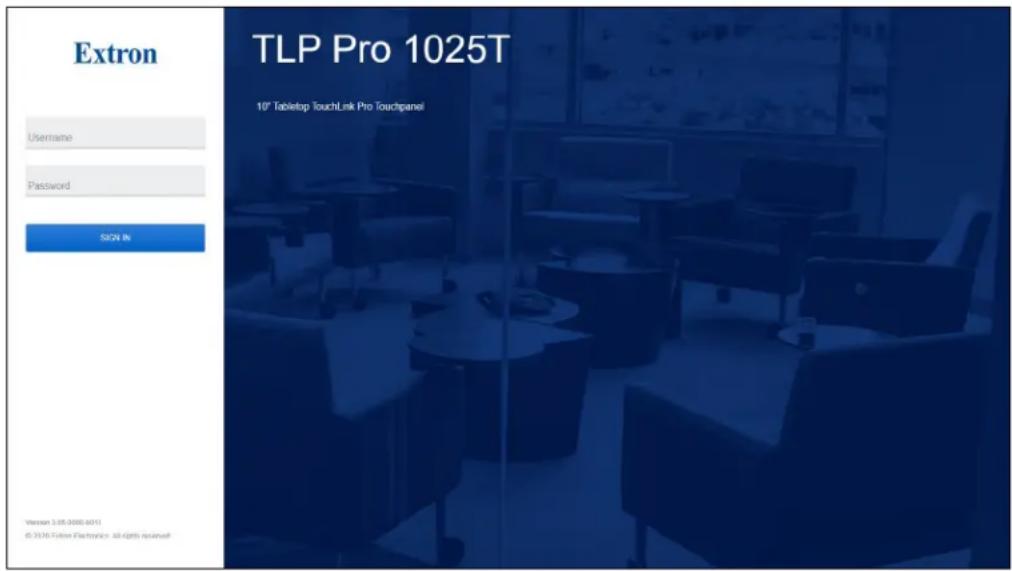
Figure 24. TLP Pro 1025T Login Page
Figure 24 shows the login page for the TLP Pro 1025T. The login pages for the other touchpanels are very similar. Enter the Username and Password. The factory configured passwords for all accounts on this device have been set to the device serial number. Passwords can be changed during configuration. Passwords are case sensitive.
NOTE: If the device is reset to default settings, the passwords are reset to the default password, which is extron (for either admin or user).
The web page opens. Figure 25 shows the TLP Pro 725T web page. The web pages for the other touchpanels are very similar.
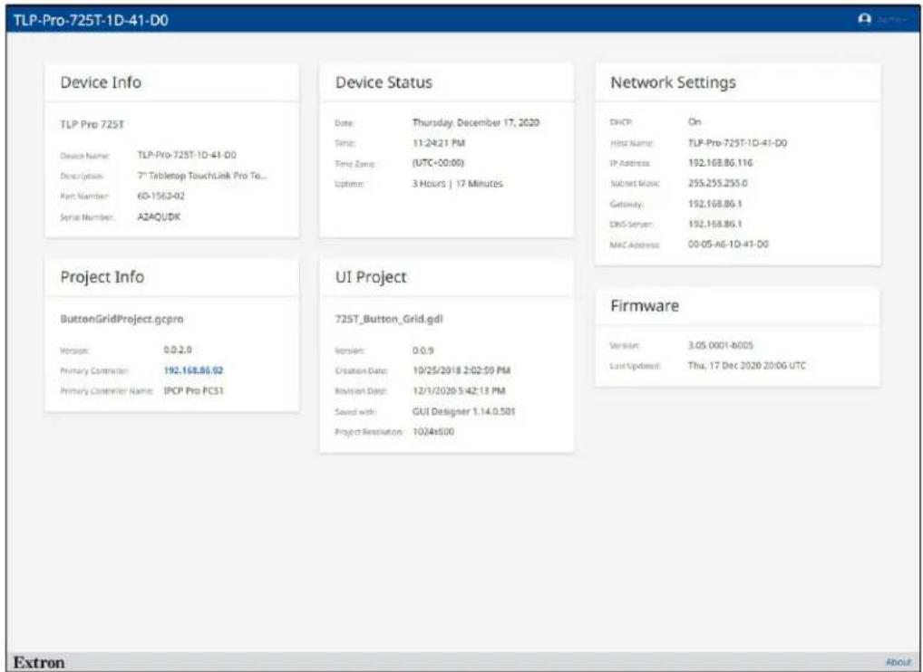
Figure 25. TLP Pro 725T Web Page
There is a single page, most of which is read-only, providing general and network information about the unit. Use the On-screen Menus (see page 16) or Toolbelt to configure the touchpanel network settings. Use Toolbelt to upgrade the unit firmware (see Updating the Firmware on page 30).
Updating the Firmware
Firmware for the TLP Pro 725 series touchpanels can be upgraded using Toolbelt. Before starting, consult your IT team and ensure that the touchpanel has a unique IP address.
Power on a computer that is connected to the same network as the touchpanel.
- On the Extron home page, select the Downloads tab (see figure 20, ①, on page 26).
- Click Firmware in the Downloads list (②).
- Start typing the product name for the firmware in the Search Firmware text box (see figure 26, 1).
The name of the firmware appears in a drop-down list.
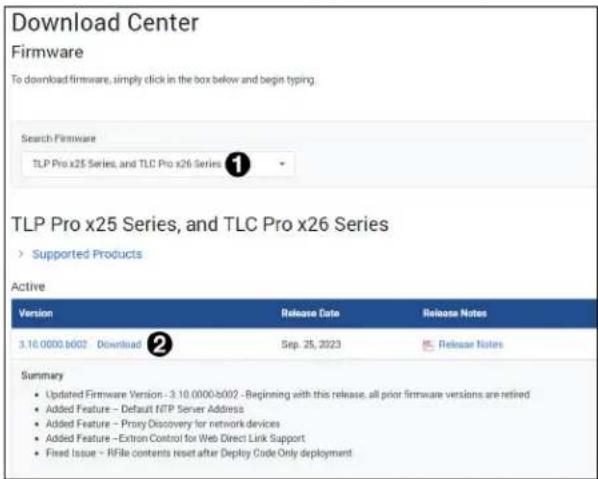
Figure 26. Firmware Download Center
- Click the Firmware name.
Information about the software appears under the Search Software text box.
- Click Download (②).
- Enter the required information and click the download button.
- Go to the Downloads folder and click on the file to install the firmware on the PC. By default, it is stored at C:\Program Files (x86)\Extron\Firmware\
\ . - Upload this file to the touchpanel using Toolbelt. For information about using Toolbelt to update the firmware, see the Toolbelt Help File.
Mounting
There are several options for mounting these touchpanels. Visit the Extron website (www.extron.com) for a complete list.
This section outlines the various options for:
- Mounting the TLP Pro x25M Series and TLS Series Touchpanels
- Mounting to a Wall Box or Junction Box
- Mounting to Drywall
- Mounting the Touchpanels with Optional Kits
• Mounting the TLP Pro 525T, 725T or 1025T
ATTENTION:
Mounting the TLP Pro x25M Series and TLS Series Touchpanels
NOTE: Mount the TLS 525M, TLS 725M, and TLS 1025M in exactly the same way as the corresponding TLP Pro x25M touchpanel.
Mounting to a Wall Box or Junction Box
Some local building codes require the touchpanel to be mounted in a junction box. Junction boxes or wall boxes must be purchased separately.
NOTES:
- The TLP Pro 525M and TLS 525M touchpanels mount to a 1-gang junction box and have their own mounting plate (see figure 27, top). The US 1-gang junction box should be installed so that the long side is horizontal. EU or MK 1-gang junction boxes should be installed in the standard orientation.
- The TLP Pro 725M, TLS 725M, TLP Pro1025M, and TLS 1025M touchpanels mount to a 2-gang junction box. All four of these models use the same mounting plate (see figure 27, bottom).
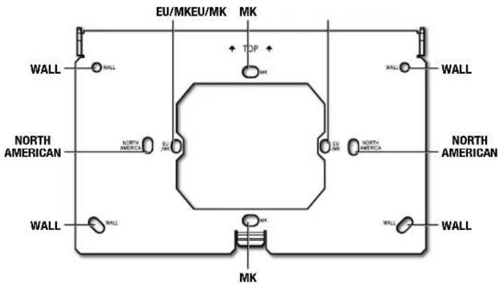
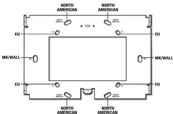
Figure 27. Mounting Plates for TLP Pro 525M (top) and TLP Pro 725M and 1025M (bottom)
Figure 28 shows how to mount the TLP Pro 725M. Mounting the all the other touchpanels is very similar.
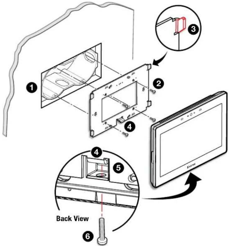
Figure 28. Mounting the TLP Pro 725M to a Wall Box (left) and Mounting Plate (right)
-
Install a junction box or wall box (see figure 28, ①), following the instructions provided by the manufacturer.
-
Make sure you have the correct mounting plate for your touchpanel and fasten it to the wall with the provided screws (②). Use the mounting holes that are appropriate to the junction box you are using (see figure 27 on page 32).
NOTES:
- Extron provides four 3/4" #6-32 Philips pan head screws for mounting to US junction boxes.
-
Extron provides two 16 mm M 3.5 Philips pan head screws for mounting to MK junction boxes.
• EU junction boxes are usually provided with their own screws. -
Run and connect cables to the back of the touchpanel (see Rear Panel Features on page 11).
-
Position the touch panel so that the mounting slots in the rear of the touchpanel align with the hooks on the mounting plate. The TLP Pro 725M and 1025M mounting plate has four hooks (③), one in each corner, top and bottom. The TLP Pro 525M mounting plate has two hooks, one in each corner at the top.
-
Move the touchpanel inwards so that slots move over the hooks.
-
Move the touchpanel down so that touchpanel is seated securely on the hooks and the tongue at the bottom of the mounting plate (4) is sitting in a groove in the bottom of the touchpanel (see inset, 5).
-
Tighten the mounting screw (6) to fasten the touchpanel to the mounting plate.
Mounting to Drywall
If local building codes do not require a wall box, you can mount the touchpanel directly into drywall.
- Go to www.extron.com and download the cut-out template for your touchpanel. Print the template at 100% size (no scaling).
- Remove the gray area in the center of the template, place the template against the wall or furniture in a suitable location, and ensure that it is level. Use the template to mark the hole that is being cut and the location of the MK slots (see figure 27 on page 32).
- Cut a hole in the wall or furniture (see figure 28, ①, on page 33).
- Drill two pilot holes at the location of the MK slots.
- Secure the mounting plate to the wall. Extron recommends using two molly bolts or SnapToggle bolts.
- Complete the installation as described in steps 3 through 7 of the previous section on page 33.
NOTE: Extron provides four 3/4" #6-32 Philips pan head screws for mounting to US junction boxes and two 16 mm M 3.5 Philips pan head screws for mounting to MK junction boxes. Screws are usually provided with EU junction boxes.
Mounting the Touchpanels with Optional Kits
A number of kits are available for mounting these touchpanels (see www.extron.com). The kits must be purchased separately and installed by following the instructions provided with the kit.
Mounting the TLP Pro 525T, 725T or 1025T
The TLP Pro 525T, 725T or 1025T can be placed on any suitable flat surface.
Desktop Mounting
No mounting kit
For additional security, secure the touchpanel to a table or desk with screws:
- Under the table top, mark the location of the two mounting holes, 2.71 inches (69 mm) apart. The distance between the mounting holes is the same for all models.
- Drill two holes through the table top from underneath.
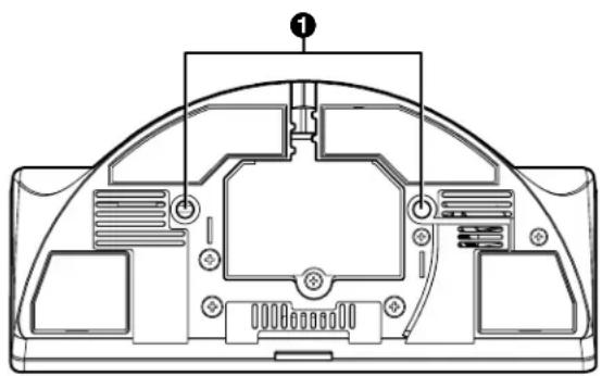
- Attach the touchpanel, using two #6-32 machine screws through the table top from underneath into the two holes in the base of the touchpanel (see figure 29, ①).
natural_image
Technical line drawing of a device rear panel with internal components and mounting holes (no text or symbols)Figure 29. TLP Pro 725T Base
SMA-2 Swivel Mount Adapter
The TLP Pro 525T, 725T, and 1025T can be mounted with the optional Extron SMA-2 swivel mount adapter, which allows it to be mounted permanently and swivel up to 180^ in either direction. The kit must be purchased separately and installed by following the instructions provided with the kit.
LinkLicenses
• What is an Extron LinkLicense?
• How Customers Obtain a LinkLicense
- Applying a LinkLicense
What is an Extron LinkLicense?
An Extron LinkLicense is a quick, cost-effective way for people to add even more powerful capabilities to Extron products. Each type of LinkLicense unlocks a unique set of features that add convenience and expand the functionality available in your system. It is applied per-system, enabling you to enhance the capabilities and performance where and when you need it. Activating a LinkLicense on a product is quick and effortless, so you can take immediate advantage of all the benefits.
For more information about Control System LinkLicenses, go to www.extron.com/product/linklicense.
How Customers Obtain a LinkLicense
Customers can obtain a LinkLicense by purchasing a redemption code and applying it to the touchpanel.
Once the LinkLicense is purchased, the end-user receives a redemption code. Go to the Extron LinkLicense Redemption webpage (www.extron.com/download/linklicense.aspx).
Enter the redemption code and the touchpanel serial number.
Once the serial number is verified, follow the prompts to download the LinkLicense activation file from the Extron LinkLicense Redemption webpage or obtain it as an attachment from an automated email.
Applying a LinkLicense
The LinkLicense activation file can be applied to the touchpanel using Toolbelt. For more information about Toolbelt, see the Toolbelt Help File.
- Open Toolbelt.
- Connect the touchpanel.
- Open the LinkLicense tab.
- Press the ... menu button.
- Find the LinkLicense activation file.
- Click Apply.
The LinkLicence is applied to the touchpanel.
NOTE: Once the redemption code is used in the Extron website, the LinkLicense is tied (locked) to the specific device serial number entered into the form. This means that the code cannot be transferred to another device after the code has been used.
Reference Material
This section describes:
• Best Practices for Cleaning Your Extron Products
• Network Port Requirements and Licensed Third-Party Software Used by the Touchpanels
• Digital I/O Port Cases
- Reset Modes
- Secure Sockets Layer (SSL) Certificates
• IEEE 802.1X Certificates
• SNMP
Best Practices for Cleaning Your Extron Products
Depending on the device, application, and location, there may be times when it becomes necessary to clean your Extron product. Frequently touched devices, such as touchscreens and button panels, require regular cleaning to ensure their surfaces remain sanitary. Plastic surfaces and cosmetic finishes can be damaged by long term exposure to chemicals. Therefore, Extron recommends the following guidelines when cleaning our products.
All Extron products can be safely cleaned with:
- 70% concentration or higher isopropyl alcohol
• Disinfectant cleaners that:
- Are non-ammonium based (for example, contains no ammonium chloride)
- Contain 2% or less sodium hypochlorite (for example, 2% bleach, 98% water)

natural_image
Illustration of a blue glove resting on a beige sheet of paper (no text or symbols)Regardless of the device, it is important to follow these general guidelines when cleaning:
- If possible, unplug the device.
- Spray the cleaner on a lint-free cloth until the cloth is damp.
- Do not spray the cleaner directly onto the product.
- Gently clean the product surface using the cloth.
Your health and safety are our top priority. Keeping devices clean, especially those in high-traffic environments and high-use applications, is a crucial step in minimizing the spread of infections. Please contact us if you have any questions about the guidelines outlined in this section or if you have a question about cleaning a specific Extron product.
Network Port Requirements and Licensed Third-Party Software Used by the Touchpanels
For information about network port requirements and licensed third-party software for all the touchpanels described in this guide, please refer to the Extron Control Product Network Ports and Licenses Guide (for TLP Pro touchpanels) or TouchLink Scheduling Panels Network Ports, Protocols, and Licenses (for TLS touchpanels) which are both available at www.extron.com.
Digital I/O Port Cases
Connecting an Occupancy Sensor to the Digital I/O Port
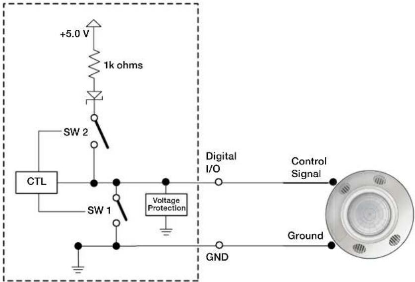
Figure 30. Connecting an Occupancy Sensor to the Digital I/O Port
Port Configured — Input (switch 1 open, switch 2 open)
Room Occupied — Digital input reads +2.8 to 24 VDC = Logic High
Room Unoccupied — Digital Input reads 0 VDC = Logic Low
NOTE: An occupancy sensor typically supplies +24 VDC when occupancy is detected. After a defined period when no occupancy is detected, the sensor supplies 0 VDC.
Connecting a Two-position Switch to the Digital I/O Port
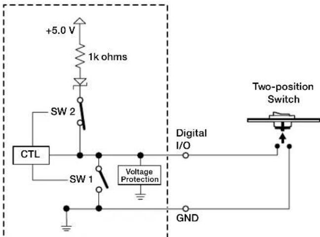
Figure 31. Connecting a Two-position Switch to the Digital I/O Port
Port Configured — Input with pullup (switch 1 open, switch 2 closed)
Two Position Switch Open — Digital input reads +5 VDC = Logic High
Two Position Switch Closed — Digital Input reads 0 VDC = Logic Low
Reset Modes
The touchpanels described in this guide have three reset modes that are initiated by pressing the RESET button. An additional (fourth) mode toggles between enabling and disabling the DHCP client:
• Use Factory Firmware (see below).
- Reset Network Settings (see page 39).
• Full Factory Reset (see page 39).
- Toggle DHCP Client (see page 40)
The RESET button is found on the rear panel of the TLP Pro 525M, 725M, and 1025M series (see figure 4, B, on page 11) or the base of the TLP Pro 525T, 725T, or 1025T series (see figure 5, B, on page 13).
Use Factory Firmware
This mode is used to boot up the unit with factory-installed firmware for a single power cycle if a firmware update fails or incompatibility issues arise with user-loaded firmware.
Activation
To start the Use Factory Firmware reset mode and replace firmware:
- Remove power from the touchpanel.
- On the touchpanel, hold down the recessed RESET button (see figure 4, B or figure 5, B) while re-applying power to the unit. When power is restored, the Reset LED lights. Hold the RESET button for a further 2 seconds before releasing it. The touchpanel enters factory firmware mode.
- Upload new firmware to the unit as desired (see Updating the Firmware on page 30).
NOTE: Do not continue to operate the touchpanel using the factory firmware version. If you want to use the factory default firmware, you must upload that version again (see Updating the Firmware).
Result
The unit reverts to factory-installed firmware. Event scripting does not start if the unit is powered on in this mode. All user files and settings such as drivers, adjustments, and IP settings are maintained.
NOTE: To return the unit to the firmware version that was running prior to the reset, cycle power to the unit.
Reset Network Settings
This mode resets all IP settings to factory defaults.
Activation
To reset all IP settings:
- Hold down the RESET button for about 6 seconds until the Reset LED blinks twice (once at 3 seconds and again at 6 seconds).
- Release and press RESET momentarily (for <1 second) within 1 second. Nothing happens if the momentary press does not occur within 1 second.
Result
Reset All IP Settings mode:
- Sets the IP address back to factory default (192.168.254.251).
- Sets the subnet back to factory default (255.255.255.0).
- Sets the default gateway address to the factory default (0.0.0.0).
- Sets all other IP settings, addresses, and domain and host names back to factory default.
- Turns DHCP off.
Full Factory Reset
This mode resets all IP settings and touchpanel settings, including passwords, to factory defaults and removes all configurations. It allows you to start over with configuration and uploading.
NOTES:
- The factory configured passwords for all accounts on this device have been set to the device serial number. Passwords can be changed during configuration. Passwords are case sensitive.
- If the device is reset using Full Factory Reset, the password is the default password configuration. The default password is extron (for either admin or user accounts).
Activation
To reset the unit to all factory default settings:
- Hold down the RESET button for about 9 seconds until the Reset LED blinks three times (once at 3 seconds, again at 6 seconds, and again at 9 seconds).
- Release and press RESET momentarily (for <1 second) within 1 second. Nothing happens if the momentary press does not occur within 1 second.
Result
Reset to Factory Defaults mode performs a complete reset to factory defaults (except the firmware):
- Does everything "Reset Network Settings" mode does.
- Removes touchpanel user interface layout and configurations.
- Resets all touchpanel settings to factory default.
Toggle DHCP Client
This mode toggles between DHCP enabled and DHCP disabled. This can also be carried out from the Network screen (see page 19) of the Setup menu.
Activation
To enable or disable the DHCP client for the LAN port:
- Press the RESET button five times (consecutively).
- Release the button. Do not press the button within 3 seconds, following the fifth press.
Result
If DHCP was enabled, it is now disabled. The Reset LED blinks three times.
If DHCP was disabled, it is now enabled. The Reset LED blinks six times.
NOTES:
- DHCP toggle mode is supported on firmware version 3.0 or higher.
- By default DHCP is off and the unit uses a static IP address.
- When you disable DHCP, the unit reverts to using the previously-set static IP address.
Secure Sockets Layer (SSL) Certificates
Extron TouchLink Pro control systems ship with factory-installed SSL certificates created by Extron. If you want or are required to use a different SSL certificate at your installation site, then you can use system utilities in the Toolbelt software to change the SSL certificate at any time. The Toolbelt Help File provides instructions on how to apply an SSL certificate to a controller.
NOTES:
- You must run Toolbelt as an administrator.
- Some certificates require a passphrase that is created when the certificate is created. If a passphrase is required, you must enter that passphrase before uploading and applying the certificate.
These devices support standard OpenSSL certificate encodings such as .pem (Privacy-enhanced Electronic Mail) and .der (Distinguished Encoding Rules) file types. PEM file types are ASCII encoded and are the required format for uploading to the Extron control product. DER file types are binary encoded and can typically have several file extension variations, such as .crt and .cer. There are many standard tools that can convert from DER to PEM file encodings if needed.
NOTE: A DER format file must be converted to PEM encoding before uploading it to the button panel, control processor, or collaboration receiver.
To properly create the certificate for uploading to Extron control devices, ensure that the certificate file meets the following requirements:
- contains X.509 certificate information
• contains public and private keys - uses PEM encoding
NOTE: ITU-T standard X.509 covers aspects of public key encryption, digital cryptography, certificates, and validation.
Contact your IT administrator for more information on what tools and policies are required to obtain or create the SSL certificate and, if necessary, the corresponding passphrase.
IEEE 802.1X Certificates
IEEE 802.1X is a standard that enables port-based network access control via an authentication server. The protocol requires that all devices must be authenticated before gaining privileges to access the secure part of the network.
The Extron implementation of 802.1X supports PEAP - MSCHAPV2 and EAP - TLS methods of authentication. This section of the guide details the “Certificate File Requirements” and the “Private Key File Requirements” to be used in the system (see below).
Extron provides resources for learning about 802.1X implementation:
The Extron 802.1X Technology Reference Guide, available from www.extron.com, is the primary resource for background information, system planning, topology, and how to set up these systems.
The Toolbelt Help file provides detailed step-by-step information on using the software to set up 802.1X for IP Link Pro control systems and on troubleshooting.
The 802.1X Primer white paper, also available from www.extron.com, provides a general overview of the protocol and its use within a control system.
NOTES:
- You must run Toolbelt as an administrator.
- Machine certificates require a private key file, which can be encrypted.
Certificate File Requirements
PEM (Privacy-enhanced Electronic Mail) file types are ASCII encoded, and they are the required format for 802.1X authentication for the TouchLink Pro control systems. DER (Distinguished Encoding Rules) file types are binary encoded and can typically have several file extension variations, such as .crt and .cer.
NOTE: DER encoded files (files with .der, .crt, or .cer extensions that are encoded in DER binary format) must be converted to a PEM encoded file type (.pem) before being used for authentication.
DER encoded certificates must be converted to PEM encoding using a third-party tool. Contact your IT administrator for more information on required tools.
To create the 802.1X security certificate for uploading to Extron TouchLink Pro control systems, ensure that the certificate file meets the following requirements:
- It contains X.509 certificate information.
- It contains a private key (for machine certificates only).
- It is PEM encoded.
• It has a file extension that is .crt or .pem - Its file name consists of the following types of valid characters:
• Alphanumerical (A-Z, a-z, 0-9) characters
• Some special characters (colon [:], underscore [ ], and hyphen [-])
NOTE: Spaces are not permitted anywhere in the name.
Private Key File Requirements
Private key files are required only when employing machine certificates. Follow these requirements for creating a private key:
- Its file name consists of the following types of valid characters:
• Alphanumerical (A-Z, a-z, 0-9) characters
• Some special characters (colon [:], underscore [ ], and hyphen [-])
• It has a file extension that is .key or .pem. - It can have optional encryption (via password or passphrase).
SNMP
Extron control products support Simple Network Management Protocol (SNMP). SNMP facilitates the exchange of basic network management information between network devices. It helps in monitoring of operations and factors such as packet usage, memory usage, remote password resets, and collection of error information. An information technology administrator can use common IT tools to monitor those factors, as well as look up device location and the name of the contact person for the device.
The SNMP controls within Toolbelt provide a way to enable or disable SNMP. It also allows you to specify related information such as the name of a contact person, the physical location of the unit, and a community name. The text that is specified in these fields is seen by the network community when the unit is queried.
Extron control products support the following security levels:
• Management Information Base 2 (MIB-II)
- SNMPv2c.
Extron Warranty

Extron warrants its powered products against defects in materials and workmanship for a period of three years from the date of invoice. In the event of malfunction during the warranty period, Extron will repair or replace a products to whatever extent it shall deem necessary to restore the product to proper operating condition.
This Limited Warranty does not apply if the fault has been caused by misuse, improper handling care, electrical or mechanical abuse, abnormal operating conditions or non-Extron authorized modification to the product. Extron Electronics makes no further warranties either expressed or implied with respect to the product and its quality, performance, merchantability, or fitness for any particular use. In no event will Extron Electronics be liable for direct, indirect, or consequential damages resulting from any defect in this product even if Extron Electronics has been advised of such damage. Please note that laws vary from state to state and country to country, and that some provisions of this warranty may not apply to you.
Powered Warranty Exception
Everlast™ Power Supplies — Extron warrants Everlast power supplies against any defects in materials and workmanship for a period of seven years from the date of invoice. In the event of a malfunction during the warranty period, Extron will repair or replace the power supply to its original operating condition. Extron engineers will examine the returned product and determine whether the Everlast Power Supply Warranty or Powered Product Warranty applies.
Speakers — Extron warrants Flat Field®, SoundField®, SpeedMount®, Column Array, and System INTEGRATOR® speakers against any defects in materials and workmanship for a period of five years from the date of invoice.
Touchscreens — Extron warrants touchscreen display and overlay components against any defects in materials and workmanship for a period of one year from the date of invoice.
Annotator 300 — Extron warrants the Annotator 300 against any defects in materials and workmanship for a period of five years from the date of invoice.
Non-Powered Warranty Exception
Cable Cubby, Hideaway Surface Access Enclosures and Retractors — Extron warrants Cable Cubby cable access enclosures, HSA Hideaway Surface Access enclosures, and Retractor cable retraction modules for a period of three years from the date of invoice.
Active Cables and Active Adapters — Extron warrants active cables and active adapter cables for a period of three years from the date of invoice.
Cable Termination Tools and Dies — Extron warrants cable termination tools for a period of three years from the date of invoice, excluding the die.
Return Information
Units must be returned insured, with shipping charges prepaid. If not insured, you assume the risk of loss or damage during shipment. Returned units must include the serial number and a description of the problem, as well as the name of the person to contact in case there are any questions.
NOTE: To assure the highest level of service, a return authorization number must be obtained from Extron before products are returned for service. Products must be shipped to Extron, prepaid along with proof of purchase only after obtaining a Return Authorization (RA) number from the Extron Customer Support department.
Please contact Extron to receive an RA (Return Authorization) number:
USA: 714.491.1500 or 800.633.9876
Asia: 65.6383.4400
Europe: 31.33.453.4040 or 800.3987.6673
Japan: 81.3.3511.7655
Africa and Middle East: 971.4.299.1800
- TLP Pro x25 Series and TLS x25 Series
- Safety Instructions
- Safety Instructions • English
- FCC Class B Notice
- Battery Notice
- Class 1 Laser Product
- Antenna Warnings
- Compliance IC
- CAN ICES-3 (B)/NMB-3(B)
- IC Antenna Statement
- Radio Frequency (RF) Exposure Information
- IC conformité
- Conventions Used in this Guide
- Notifications
- Software Commands
- Specifications Availability
- Extron Glossary of Terms
- Contents
- Introduction....1
- Installation Overview....7
- Panel Features....9
- On-screen Menus 16
- Configuration Software....25
- Mounting 31
- LinkLicenses....35
- Reference Material....36
- Extron Warranty....43
- Introduction
- About This Guide
- About the Touchpanels
- Features
- All Models
- TLP Pro Series Touchpanels
- TLP Pro 525M, TLP Pro 725M, and TLP Pro 1025M
- TLP Pro 525T, TLP Pro 725T, and TLP Pro 1025T
- TLS 525M, TLS 725M, and TLS 1025M
- Requirements
- Software
- Hardware
- Installation Overview
- Mount and cable the units:
- ATTENTION:
- Panel Features
- Front Panel Features
- Rear Panel Features
- TLP Pro 525T, TLP Pro 725T, and TLP Pro 1025T Base
- Connecting Power
- Setup Menu
- Status
- LinkLicenses
- Enable LinkLicenses
- NOTES:
- Disable LinkLicenses
- System Information
- Network
- Display
- Configuring the Motion Sensor
- Audio
- Advanced
- System and GUI Project Panels
- Menu PIN
- Rear Status Lights
- Communication LED
- Configuration Software
- TLS Touchpanels
- TLP Pro Touchpanels
- Installing Software
- Using the Software
- TLP Pro 525, 725, and 1025 Series Web Page
- Updating the Firmware
- Mounting
- Mounting the TLP Pro x25M Series and TLS Series Touchpanels
- Mounting to a Wall Box or Junction Box
- Mounting to Drywall
- Mounting the Touchpanels with Optional Kits
- Mounting the TLP Pro 525T, 725T or 1025T
- Desktop Mounting
- No mounting kit
- SMA-2 Swivel Mount Adapter
- What is an Extron LinkLicense?
- How Customers Obtain a LinkLicense
- Applying a LinkLicense
- Reference Material
- Best Practices for Cleaning Your Extron Products
- Network Port Requirements and Licensed Third-Party Software Used by the Touchpanels
- Digital I/O Port Cases
- Reset Modes
- Use Factory Firmware
- Activation
- Result
- Reset Network Settings
- Full Factory Reset
- Toggle DHCP Client
- Secure Sockets Layer (SSL) Certificates
- IEEE 802.1X Certificates
- Certificate File Requirements
- Private Key File Requirements
- SNMP
- Extron Warranty
- Powered Warranty Exception
- Non-Powered Warranty Exception
- Return Information
Brand : Extron
Model : TLP Pro 1025M
Category : Monitor