
TLP Pro 1725MG - Monitor Extron - Free user manual and instructions
Find the device manual for free TLP Pro 1725MG Extron in PDF.


| Product Type | Touchpanel Monitor |
| Display Size | 17.5 inches diagonal |
| Resolution | 1920 x 1080 (Full HD) |
| Touch Technology | Projected Capacitive Touch |
| Brightness | 400 cd/m² |
| Contrast Ratio | 1000:1 |
| Viewing Angle | 178° horizontal / 178° vertical |
| Connectivity | Ethernet (PoE), USB 2.0, RS-232, Audio In/Out |
| Power Supply | Power over Ethernet (PoE) or external 12V DC adapter |
| Power Consumption | 25 W typical |
| Dimensions (W x H x D) | 17.0 x 10.7 x 2.2 inches (432 x 272 x 56 mm) |
| Weight | 8.8 lbs (4.0 kg) |
| Mounting | VESA 100 x 100 mm, desktop stand optional |
| Operating Temperature | 32 to 104°F (0 to 40°C) |
| Operating Humidity | 10% to 85% non-condensing |
| Key Functions | AV control, room scheduling, digital signage |
| Cleaning & Maintenance | Use a soft, dry cloth; avoid solvents or abrasives |
| Safety Instructions | Use only with approved power sources; do not block vents |
| Spare Parts & Repairability | Contact Extron authorized service centers |
| General Information | Designed for professional AV control systems |
Frequently Asked Questions - TLP Pro 1725MG Extron
User questions about TLP Pro 1725MG Extron
0 question about this device. Answer the ones you know or ask your own.
Ask a new question about this device
Download the instructions for your Monitor in PDF format for free! Find your manual TLP Pro 1725MG - Extron and take your electronic device back in hand. On this page are published all the documents necessary for the use of your device. TLP Pro 1725MG by Extron.
USER MANUAL TLP Pro 1725MG Extron
TLP Pro 1225MG, 1525MG, and 1725MG • Setup Guide

Overview
The Extron® TLP Pro 1225MG, TLP Pro 1525MG, and TLP Pro 1725MG are wall-mounted touchpanels with capacitive, edge-to-edge glass touchscreens. The TLP Pro 1225MG has a 12.1 inch screen with a 1280x800 resolution. The TLP Pro 1525MG has a 15.6 inch screen with a 1366x768 resolution. The TLP Pro 1725MG has a 17.3 inch screen with a 1920x1080 resolution. All three touchpanels are ideal for any AV applications requiring large touchpanels with flexible mounting options and fully customizable interfaces. This guide provides instructions for experienced installers to mount and install these touchpanels. For more complete details, see the TLP Pro 1225, 1525, and 1725 Series User Guide at www.extron.com.
Setup Checklist
Get Ready
☐ Download and install the latest version of the following software:
☐ GUI Designer — Used to design layouts for Extron TouchLink® Pro touchpanels and third party touch interfaces.
Global Configurat®Plus and Professional – Used to set up and configure the control processor and touchpanel.
Global Scripter- Used to provide an integrated development environment for Extron control systems programming. Global Scripter provides an Extron-exclusive Python ™ library (ControlScript ® ) and modules to get you started.
□ Toolbelt — Used for device discovery, device information, firmware updates, and configuration of network settings, system utilities, and user management for TouchLink Pro devices.
NOTE: All four software programs are available from www.extron.com.
☐ Obtain the following network information from your network administrator:
☐ DHCP status (on or off). If DHCP is off, you also require:
IP address
□ Subnet mask
Gateway
□ Username — This can be either admin or user.
☐ Passwords — The factory configured passwords for all accounts on this device have been set to the device serial number. Passwords can be changed during configuration. Passwords are case sensitive.
NOTE: If the device is reset to default settings, the passwords are reset to the default password, which is extron (for either admin or user).
☐ Make a note of the touchpanel MAC address from the label on the back of the device.
Mount and Cable All Devices
ATTENTION:
☐ Mount the units. There are several mounting options for TouchLink Pro touchpanels (see Mounting on page 2).
☐ Connect cables to the touchpanels (see Rear Panel Features on page 4).
☐ Connect the touchpanel to a Power over Ethernet (PoE) injector. The TLP Pro 1725MG ships with the PI 140 power injector. A power injector must be purchased separately for the 12-inch and 15-inch models.
□ Connect an Extron IP LinRro control processor to the same Ethernet subnetwork as the touchpanel.
Set up the Touchpanels for Network Communication
☐ Connect the PC that you will use for setup, the control processor, and touchpanel to the same Ethernet subnetwork.
☐ Use the Setup Menu (see page 6) or Toolbelt (see Toolbelt Help File) to set the DHCP status and, if necessary, the IP address, subnet mask, gateway, and related settings for the touchpanel.
Configure the Touchpanels
□ Create a graphical user interface with GUI Designer (see GUI Designer Help File for step-by-step instructions).
☐ Associate functions with the graphical user interface features by configuring (see the Global Configurator Help File) or programming (see the Global Scripter Help File) the system.
Mounting
ATTENTION:
The touchpanels can be wall mounted using the provided hardware. Where local codes require a rear metal enclosure, either model can be mounted using the Extron BB 700M (not provided). Figure 1 shows the TLP Pro 1525MG. Mount the TLP Pro 1225MG or TLP Pro 1725MG in the same way.
With a wall box
Some local building codes require the touchpanel to be mounted in a wall box such as the Extron BB 700M. This installation procedure is described below.
-
Cut a hole in the drywall, 9.6 inches (243 mm) wide x 6.6 inches (166 mm) high, and install the BB 700M (see figure 1, ①), as described in the BB 700M Installation Guide (see www.extron.com).
-
Place the metal mounting plate against the wall, mark the four mounting holes, and drill four pilot holes (②) in those locations.
-
Secure the mounting plate with four #10 screws (③).
-
Run and connect cables to the back of the touchpanel (④, and see Rear Panel Features on page 4).
-
Insert the two provided Phillips pan head #6-32 x 3/4 inch length screws with washers in the mounting screw slot (⑤, see figure 1, Back View inset). Leave a gap for the flange at the bottom of the mounting plate to fit into.
-
Hold the touchpanel at a slight angle and lower the notches at the top of the back panel over the hooks of the mounting plate (6).
-
Swing the bottom of the touchpanel inwards so that it lies flat against the mounting plate with the flange at the bottom of the mounting plate sitting in a groove in the bottom of the touchpanel.
-
Secure the touchpanel to the mounting plate with the mounting screws (7).
Without a wall box
If the wall box is not required by local building codes, you can mount the touchpanel directly into drywall.
-
Download the cut-out template for your touchpanel from www.extron.com. Print it at 100% (no scaling).
-
Use the template to mark the wall, cut the hole, and drill the four pilot holes. The size of the cut-out hole is 9.25 inches (235 mm) wide x 6.25 inches (159 mm) high.
-
Secure the mounting plate and complete the installation, as described in steps 3 through 8 above.

Figure 1. TLP Pro 1525MG Mounting
Rack Mounting
These touchpanels can be mounted in any standard 19-inch equipment rack, using the optional rack mounting kit. The TLP Pro 1225MG can be mounted with the RM2 mounting kit. The TLP Pro 1525MG and the TLP Pro 1725MG can be mounted in the RM3 mounting kit. Read the "Underwriters Labs Guidelines for Rack Mounting" section of the TLP Pro 1225, 1525, and 1725 Series User Guide and follow the instructions provided with the appropriate kit.
Front Panel Features
Figure 2 shows the TLP Pro 1225MG front panel. The TLP Pro 1525MG and TLP Pro 1725MG features are very similar.

Figure 2. TLP Pro 1225MG Front Panel
A Ambient light sensor — Monitors ambient light level and adjusts screen brightness.
B Status light — Can be programmed to provide system feedback. This LED light bar is located above the screen.
C Capacitive touch screen — Provides simple control of AV systems.
• The TLP Pro 1225MG has a 12.1 inch screen with a 1280x800 resolution.
• The TLP Pro 1525MG has a 15.6 inch screen with a 1366x768 resolution.
• The TLP Pro 1725MG has a 17.3 inch screen with a 1920x1080 resolution.
D Speakers — Provide stereo audio for video preview and audible feedback from button presses. They are located below the screen, one on each side of the panel.
E Motion sensor — Detects motion between three to five feet from the touchpanel, and at least 15° from the center axis.
- If the sleep timer feature has been set, and no motion has been detected for a user-defined period of time, the touchpanel enters sleep mode.
- If the wake on motion feature has been set, and motion is detected by the sensor while the screen is in sleep mode, the screen display is restored and active.
For more information about setting the Sleep Timer or Wake on Motion, see the "Setup Menu" section of the TLP Pro 1225, 1525, and 1725 Series User Guide.
F Menu button — Activates the setup menu (see Setup Menu). Access the button from under the touchpanel. It performs the same function as the rear panel Menu button but is easier to reach when the touchpanel is installed.
Rear Panel Features
Figure 2 shows the TLP Pro 1225MG rear panel. The TLP Pro 1525MG and TLP Pro 1725MG features are very similar.

Figure 3. TLP Pro 1225MG Rear Panel
A Mounting plate notch (2) — Fit over the hooks at the top of the mounting plate (see Wall Mounting on page 2).
B RESET LED — Provides feedback about the reset status when the user presses the reset button.
RESET button — Pressing the RESET button allows the unit to be reset in any of three different modes (see Reset Modes: a Brief Summary on page 5). For more information, see the TLP Pro 1225, TLP Pro 1525, and TLP Pro 1725 Series User Guide.
D MENU button — Activates the setup menu (see Setup Menu).
E USB connectors (2) — For peripheral controls.
F Mounting screw slot (2) — Insert the provided screws here to secure the touchpanel to the mounting plate.
G Audio output — One 3.5 mm line level audio output for use with headphones or assistive listening devices.
H HDMI input — For alternative video input.
① XTP/LAN/PoE input
- XTP input — Connect the touchpanel to an Extron XTP® source using a twisted pair cable, terminated with an RJ-45 connector. For complete information about which cables to use, see the user guide for your XTP product.
• LAN input — Connect the touchpanel to the LAN using a twisted pair cable, terminated with an RJ-45 connector. - PoE input — the connector can be used with a PoE power injector (see Connecting Power on page 5).
NOTE: Some XTP models are able to remotely power these touchpanels but not all have that capability. Go to the Extron website and check the product page for your XTP model to ensure it can power your touchpanel.
An Extron IP Link Pro control processor must also be connected to the same network as the TouchLink Pro touchpanel.
Connecting Power
ATTENTION:
- Do not power on the touchpanels until you have read the Attention in the "Rear Panel Features" section of the TLP Pro 1225, 1525, and 1725 Series User Guide.
- Ne branchez pas les écrans tactiles avant d'avoir lu la mise en garde dans la section « Rear Panel Features » du TLP Pro 1225, 1525, and 1725 Series User Guide.
The TLP Pro 1725MG ships with the Extron PI 140 power injector included. For the TLP Pro 1225MG and TLP Pro 1525MG, the power injector must be purchased separately. Figure 4 shows the PI 140. Your power injector may look different.
- Connect a straight-through Ethernet cable from the power injector to a switch or router (see figure 4, ①). This cable carries network information from the switch or router to the power supply input.
- Connect a second straight-through cable (②) from the power injector to the TLP Pro touchpanel XTP/LAN/PoE connector (see figure 3, ①, on page 4). This cable carries the network information and 48 VDC from the power injector to the touchpanel.
- Connect the IEC power cord to a convenient 100 VAC to 240 VAC, 50-60 Hz power source (figure 4, ③).
Alternatively, use an Ethernet cable to connect the XTP/LAN/PoE port of the interface to a PoE+ switch or connect the touchpanel directly to an XTP model that is capable of remotely powering a touchpanel (see the note on page 4).

Figure 4. Connecting the Power Injector
Reset Modes: a Brief Summary
These touchpanels offer the following reset modes. For full information about the modes, see the TLP Pro 1225, 1525, and 1725 Series User Guide.
- Use factory firmware:
Use this mode to replace firmware in the event of firmware failure. Press and hold the RESET button (see figure 3, Ⓐ) while applying power to the unit.
- Reset All IP Settings:
Use this mode to reset all network settings without affecting user-loaded files. Press and hold the RESET button for 6 seconds. After the RESET LED (B) blinks twice, release and momentarily press the RESET button.
- Reset to Factory Defaults:
Use this mode to return the interface to factory default settings. Press and hold the RESET button for 9 seconds. After the RESET LED blinks three times, release and momentarily press the RESET button.
NOTES:
- The factory configured passwords for all accounts on this device have been set to the device serial number. Passwords can be changed during configuration. Passwords are case sensitive.
- If the device is reset to default settings, the passwords are reset to the default password, which is extron (for either admin or user).
- Enable or Disable the DHCP Client:
Use this mode to toggle between DHCP enabled and DHCP disabled.
Press the RESET button five times, consecutively. After the fifth press, do not press the button again within 3 seconds. If DHCP was enabled, it is now disabled and the RESET LED blinks three times. If DHCP was disabled, it is now enabled and the RESET LED blinks six times.
NOTES:
- By default DHCP is off and the unit uses a static IP address.
- When you disable the DHCP client, the unit reverts to using the previously-set static IP address.
TLP Pro 1225MG, 1525MG, and 1725MG • Setup Guide
Setup Menu
Press the MENU button (figure 2, F on page 3 or figure 3, D, on page 4) to open the setup menu. Select any of the six available screens (Status, Network, Display, Audio, Input and Advanced) by tapping the appropriate button in the navigation bar at the top of the screen (for more information, see the TLP Pro 1225, 1525, and 1725 Series User Guide).
Figure 5 shows the setup menu for the TLP Pro 1225MG. The setup menu for the TLP Pro 1525MG and TLP Pro 1725MG are very similar.
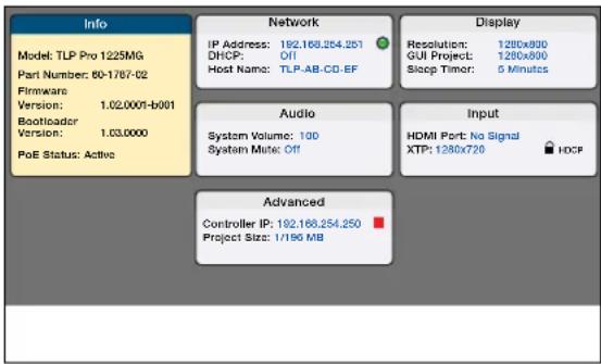
Figure 5. Setup Menu: Status page for TLP Pro 1225MG
For information on safety guidelines, regulatory compliances, EMI/EMF compatibility, accessibility, and related topics, see the Extron Safety and Regulatory Compliance Guide on the Extron website. For information about replacing and disposing of batteries, see the TLP Pro 1225, 1525, and 1725 Series User Guide at www.extron.com.


- TLP PRO 1225MG, 1525MG, AND 1725MG • SETUP GUIDE
- OVERVIEW
- SETUP CHECKLIST
- GET READY
- MOUNT AND CABLE ALL DEVICES
- ATTENTION
- SET UP THE TOUCHPANELS FOR NETWORK COMMUNICATION
- CONFIGURE THE TOUCHPANELS
- MOUNTING
- WITH A WALL BOX
- WITHOUT A WALL BOX
- RACK MOUNTING
- FRONT PANEL FEATURES
- REAR PANEL FEATURES
- CONNECTING POWER
- RESET MODES: A BRIEF SUMMARY
- NOTES
- SETUP MENU
Brand : Extron
Model : TLP Pro 1725MG
Category : Monitor