
Straight Shaft Helm Drive - Commande de direction bateau SIMRAD - Free user manual and instructions
Find the device manual for free Straight Shaft Helm Drive SIMRAD in PDF.


| Product Type | Straight Shaft Helm Drive |
| Brand | Simrad |
| Model | Straight Shaft Helm Drive |
| Material | Stainless Steel and Aluminum |
| Shaft Length | Typical 3-4 ft (custom lengths available) |
| Weight | Approximately 8-12 lbs |
| Power Source | Manual (no electrical power required) |
| Primary Function | Converts helm wheel rotation into steering cable movement |
| Compatibility | Compatible with most mechanical steering systems |
| Installation | Mounts directly to helm console; requires proper alignment |
| Maintenance | Periodic lubrication of shaft and bearings |
| Cleaning | Wipe with damp cloth; avoid harsh chemicals |
| Safety Notes | Ensure secure mounting to prevent steering failure |
| Spare Parts Availability | Replacement shafts, bearings, and mounting brackets available |
| Repairability | Modular design allows easy replacement of worn components |
Frequently Asked Questions - Straight Shaft Helm Drive SIMRAD
User questions about Straight Shaft Helm Drive SIMRAD
0 question about this device. Answer the ones you know or ask your own.
Ask a new question about this device
Download the instructions for your Commande de direction bateau in PDF format for free! Find your manual Straight Shaft Helm Drive - SIMRAD and take your electronic device back in hand. On this page are published all the documents necessary for the use of your device. Straight Shaft Helm Drive by SIMRAD.
USER MANUAL Straight Shaft Helm Drive SIMRAD
natural_image
Mechanical component with black steering wheel and metallic shaft, no visible text or symbols4 Introduction
4 System overview
4 Compatibility information
5 Compliance statements
5 General maintenance guide
5 Important safety features
6 Manual override
7 Mechanical installation
7 Available space - Physical Envelope & Orientation
8 Cable compatibility
10 Type S Straight Shaft Drive
15 Replacing steering cable
16 Running new steering cable
17 Rudder Feedback unit (RFB) installation and calibration
18 Electrical installation
18 Connecting drive to autopilot
19 Accessories
1
Introduction
System overview
The drive is a rotary mechanical autopilot drive system which makes it simple and economical to fit an autopilot on smaller powerboats with mechanical push-pull cable steering.
The drive unit is suitable for standard straight shaft configurations and incorporate a drive motor, solenoid clutch and integrated rudder feedback (RFB) capability.
The compact drive unit completely replaces the existing manual steering helm and is totally concealed behind the dash, giving a neat, professional installation.
Compatibility information
- The drive is recommended for use on boats with a maximum speed of 65 km/h (40 mph) and should not be fitted to boats which can exceed this.
- The drive should not be fitted to boats where the engine max horsepower exceeds the max horsepower rating for the boat as stated on the boat manufacturer's tag.
- The drive unit either replaces or is used in conjunction with common brands of mechanical rotary and rack and pinion steering helm units. The drive is based on the Morse 290 rotary helm unit and accepts Morse 304411 and Teleflex SSC52 rotary cables without modification. If the boat is fitted with any of the following systems:
Teleflex Safe T or Teleflex Big T Uflex T71, Uflex T73NR or Uflex T81
a cable adapter must be fitted to the cable before installing the drive.
- If the boat has a rack and pinion type steering system (or other brands of rotary system), the drive can be used, but the steering cable must also be replaced with a Morse 304411 or Teleflex SSC52.
- The drive is designed to produce a maximum cable push/pull of 136 kg, which makes it suitable for the vast majority of cable steered boats. However, some boats fitted with push-pull cable steering systems have very stiff steering or steering which is heavily loaded in one direction due to hull design and engine considerations. Generally speaking, the drive will steer boats that do not require more than a 7 kg force on the rim of a 35 cm diameter steering wheel to
hold a course, this equals 1.2 kgm of torque. If the steering wheel input torque exceeds this figure it is recommended that a hydraulic linear actuator drive system is used.
- If the existing steering system is a NFB (non feed back) type, the drive can be fitted, but it is strongly advised that the helmsperson is formally familiarized with the different operational characteristics of the new helm.
Compliance statements
The Simrad Straight Shaft Helm Drive;
• complies with CE under EMC directive 2004/108/EC
- complies with the requirements of level 2 devices of the Radio-communications (Electromagnetic Compatibility) standard 2008
The relevant Declaration of Conformity is available in the following website under model documentation section: www.simrad-yachting.com
General maintenance guide
- Check the complete steering system and all fixings for security and integrity after a few hours of operation and at frequent intervals
- Inspect all parts periodically for corrosion. Any parts affected by corrosion must be replaced
- Periodically remove the cable, clean the connector tube and thoroughly lubricate with a waterproof grease. Inspect the cable for cracks, splits or other damage. DO NOT cover cracks in the cable outer sheath with tape or other sealant; this will only delay a failure of the cable. Always replace the cable
- When replacing fi xings, self-locking nuts must always be used.
Important safety features
The helmsperson should be made aware of the two following safety features before using the Autopilot:
Manual release
The drive features a manual release in case the Autopilot is switched to manual mode by mistake, which could result in a dangerous manoeuvre or violent movement of the steering wheel on a powerboat due to propeller action or trim forces.
While the drive is under consistent load from the boat's steering system in one direction or no movement, the drive unit clutch will remain engaged when the Autopilot is switched to manual mode.
To disengage the drive
A small joggle action (turning the wheel/tiller from side to side) will release the clutch and allow manual control.
⚠ Warning: The helmsperson should always be ready to take manual control of the boat when the Autopilot is returned to manual mode.
Dockside testing
Due to the 'Manual Release' safety feature, when the boat is not in motion it might be necessary to joggle the wheel/tiller (move from side to side) to engage or disengage the drive.
Manual override
⚠ Warning: It is strongly advised that the helmsperson be familiarized with this manual override procedure before proceeding to sea.
In the event of uncontrolled automatic steering or any other emergency situation where it is imperative that manual control be reassumed immediately, the helmsperson can override the steering action of the drive unit by exerting force on the steering wheel in the opposite direction to the drive. This action will cause the drive unit thrust limit to "slip", allowing the helmsperson to take control.
→ NOTE The manual override does not disengage the autopilot - to resume full manual control the autopilot should be switched to standby as soon as practically possible.
2
Mechanical installation
When planning the installation, it is recommended that the following are considered:
- Ensure there is adequate space available to accommodate the drive
- Determine the compatibility of the existing steering cable and select the appropriate cable adapter if required
- Select the appropriate dashboard bezel kit and determine whether helm spacers are needed
• Determine whether any additional accessories are needed.
Available space - Physical Envelope & Orientation
The depth required behind the dashboard for the drive will vary slightly depending upon the drive type and mounting style used, but all require around 250 mm (10 in) clearance. If sufficient depth is not available it may be possible to re-route wiring harnesses or move components etc.


Physical drive envelope
Cable compatibility
The Type S drive is based on the Morse 290 rotary helm unit which accepts Morse 304411 and Teleflex SSC52 rotary steering cables.
- If you are unsure of the make/model of the steering cable fitted to the vessel, the part number and length of the cable are usually printed on the cable's outer casing near to the tiller/engine connection.
- If the existing steering system is a rack and pinion type then the steering cable must be replaced with a Morse 304411 or Telefl ex SSC52 rotary steering cable, see Cable length calculation, page 15 for instructions on calculating the cable length.
Morse 304411-xxx or Telefl ex SSC52-xx (x = length in feet)
If the boat is fitted with either of these cable types then it can be connected directly to the drive.
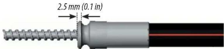
Morse 304411 and Telefl ex SSC52 steering cable
Telefl ex SSC61-xx or Telefl ex SSC62-xx (x = length in feet)
Requires a cable adapter.

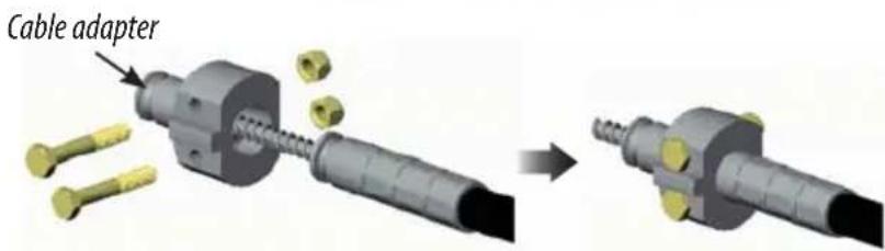
Telefl ex SSC61 or SSC62 steering cable with cable adapter fitted
Ufl ex M66-xx (x = length in feet)
Requires a cable adapter.

Ufl ex M66 steering cable with cable adapter fitted
Morse 304415-xxx, Telefl ex SSC72-xx or Ufl ex M47-xx (x = length in ft)

Morse 304415, Telefl ex SSC72 or Ufl ex M47 steering cable with cable adapter fitted
Type S Straight Shaft Drive
Mounting kits
There are two dashboard mounting options compatible with the drive system:

90° Bezel kit 000-11497-001
This kit should be used if the steering wheel is mounted 90° to the dashboard.

natural_image
Technical line drawing of a mechanical component with a 20° mounting annotation (no other text or symbols)20° Bezel kit 000-11498-001
This kit should be used if the steering wheel is mounted 20° to the dashboard.
Fitting the drive unit
- Remove the existing steering helm:
-
Remove the steering wheel
-
Unbolt and remove the helm unit*. If the existing steering is rack and pinion, the pinion will need to be unbolted from the rack before it can be removed.
*) Depending on the boat layout and accessibility to the space behind the dashboard, it may be more convenient to remove the steering cable before unbolting the existing manual helm and to refi t the steering cable after the drive has been mounted to the dashboard, rather than the order of installation given in these instructions.
- Prepare dashboard to receive drive bezel plate. Refer to illustration next page, or use the bezel plate as a template for the mounting holes that will need to be drilled:
-
Care must be taken not to damage any electrical wiring or throttle cables behind the dashboard when drilling - if necessary tape these out of the way temporarily
-
If it is necessary to enlarge the existing steering shaft hole in the dashboard for the drive unit, clamp a piece of wood over the hole as a guide for the hole saw. This will ensure that the hole is cut accurately and the hole saw doesn't jump while drilling, which could scratch or damage the dashboard.

• Fit the bezel plate to the dashboard:
1. Use the 3 x 5/16" nuts, bolts and washers supplied with the kits
2. Ensure that the nuts, bolts and washers are fitted in the correct order - the washer should be between the nut and the rear of the dashboard
3. Do not fit the plastic bezel cover at this stage.

90° bezel plate fitted to dashboard
- Remove the steering cable from the helm unit:
- Make a careful note of both the orientation of the helm unit and which side of the helm that the cable is inserted - if this is refitted incorrectly the steering will work in reverse
- Unfasten the retaining bolt or locking nut (depending on cable type) at the cable entry port
- Pull the cable retaining collar away from the helm unit
- The inner cable can be wound out by turning the steering shaft (it may help if the wheel is refitted).

Remove steering cable from existing manual helm
• Fit the steering cable:
-
Fit cable adapter to cable (if required)
-
Apply a thin coat of marine grade grease to the exposed section of the cable
-
Insert the steering cable into the drive port. Using moderate force, guide the inner cable around the driving hub and out of the opposite port
-
Push the cable jacket into the port until the retaining collar butts against the drive housing. Turn the steering shaft to wind the cable into the drive - it may help to fit the wheel in order to do this
-
Insert lock bolt to hold cable in place
-
If undue force is required to insert the cable, this may be caused by the end of the inner cable fouling the outer face of the nylon guide. If this is the case, remove the cable and inspect for sharp edges. If possible, twist the cable so that the sharp edge is towards the inside of the radius, or use a file or burr type tool to remove the sharp edges
-
Fit the spent cable tube to the opposite port and insert the lock bolt
-
Fit washers & nuts to both lock bolts, tighten & torque to 40-45 in-lbs (4 Nm).

Fitting steering cable and spent cable tube to drive unit
• Fit the drive unit to the dashboard:
-
Position the drive unit behind the dashboard and bolt it to the bezel plate using the 3 x 1/4" bolts supplied. Tighten and torque to 3-35 in-lbs.
-
Fit the plastic cover* over the bezel plate
*) This is a snap fit on the 90° bezel kit. The plastic cover on the 20° bezel kit is held in place using screws which fit the two additional holes drilled into the dashboard
- Insert the locating key ("Woodruff Key") into the recess on the steering shaft and refi t the steering wheel.

Mounting drive unit to dashboard bezel plate
- Check the installation:
-
Rotate the wheel fully from lock to lock to check that the steering works smoothly across its full range and that it is steering in the right direction
-
If the rudder moves in the opposite direction to the wheel, the cable has been inserted into the drive unit the wrong way and needs to be inserted in the other port - swap the cable and take-up tube over.
Replacing steering cable
Depending on the existing manual steering system fitted to the boat, it may be necessary to replace the steering cable with a type that is compatible with the drive (either a Morse 304411-xxx or Telefl ex SSC52-xx).
Although the replacement cable ideally will follow the same route as the existing cable, for optimum steering performance - whether under autopilot or steering manually - consideration must be given to the following points:
- The chosen route should use the minimum possible number of bends
- If any bends are necessary, maximise the bend radius as much as possible. It is recommended that bends have a radius of no less than 150 mm (6 in) and that the combined total angle of all bends is no more than 270^ .
Cable length calculation
Use a length of rope or electrical cable to plan out the steering cable route and then measure the total length required:
('A' Dimension + 'B' Dimension + 'C' Dimension) - 8 in for 2 × 90^ bend.
Round up the result to the nearest full foot size and then refer to the section for accessories, page 19 for the appropriate custom cable order code.
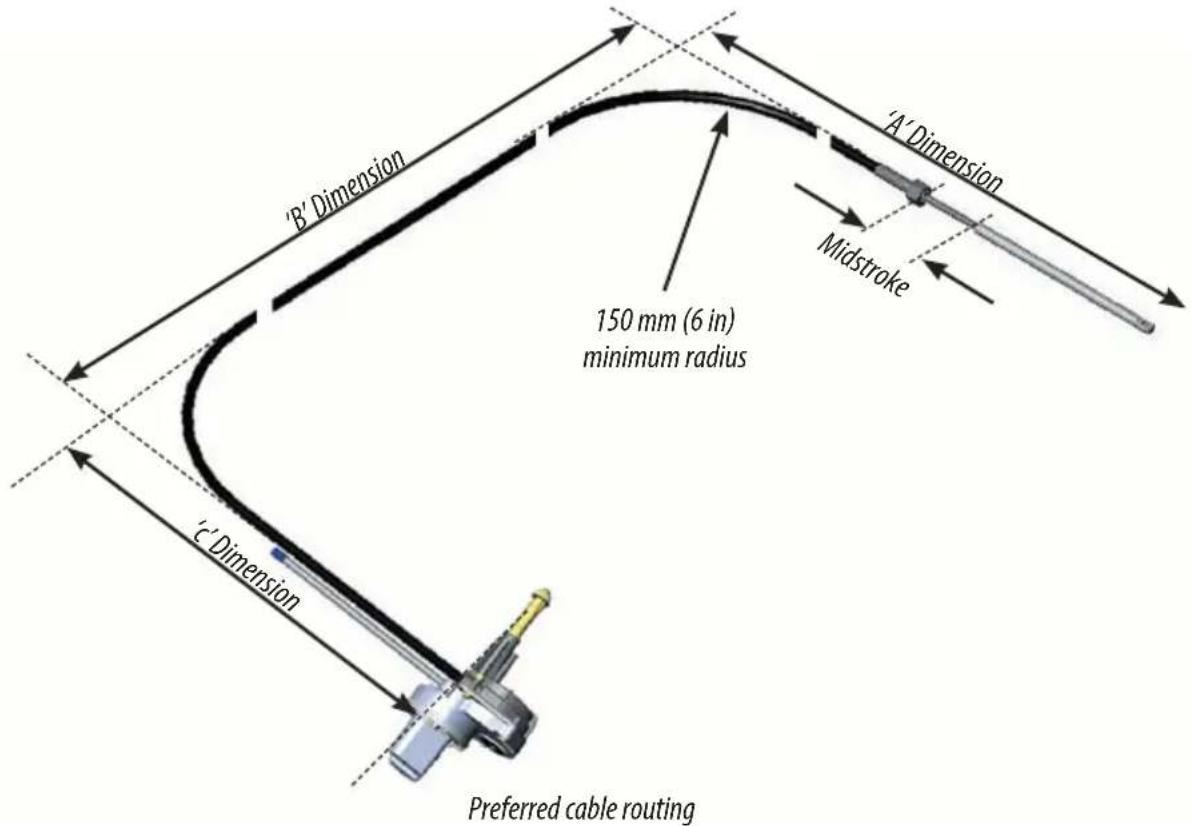
Running new steering cable

flowchart
graph TD
    A["Component 1"] --> B["Component 2"]
    B --> C["Component 3"]
    C --> D["Component 4"]
    D --> E["Component 5"]
    E --> F["Final Assembly"]
Replacing steering cable - rudder end
The accessibility of the steering cable run will depend on the size of the boat - on smaller boats the cable is usually easily accessible, but larger boats may run the cable through ducts that are more difficult to access.
- Changing the cable will be easier if a tag line (or "mouse") is attached to the end of the existing cable before it is removed. This can be used to pull the new cable through
- Use a strong line for the mouse that will not snap easily, but is thin enough to pass down the duct behind the cable
- Tie the mouse securely to the cable and use tape to reinforce the joint. Pull the cable through from the rudder end while feeding the mouse line from the steering end. When the old cable has been removed, attach the mouse to the new cable and use it to pull it back through from the rudder end.
Attach the new cable to the steering arm of the boat by pulling out the cotter pin and clevis pin to release the old steering shaft and replacing it with the new steering shaft. Line up the shaft with the steering arm by turning the steering wheel then re-insert the cotter and clevis pins.
Rudder Feedback unit (RFB) installation and calibration
The calibration routine should be performed after the drive unit has been fitted to the vessel and wired up to the autopilot. The RFB should also be electrically connected to the autopilot prior to calibration.
-
Remove the RFB module from the drive housing (if already fitted) by removing the two fixing screws
-
Center the rudder of the boat using the manual helm (you may need to run the engine to do this)
-
Calibrate the RFB by aligning the two red paint marks on the underside of the unit
-
Remove the RFB blanking cap from the drive unit housing
-
Fit the RFB to the drive housing and fix using the two screws provided. Ensure that the RFB driven gear is correctly engaged with the drive gear before tightening the 2 screws
-
Refer to the autopilot installation guide for instructions on any additional software controlled RFB fine calibration and hardover limitation.

natural_image
Mechanical gear assembly diagram with no visible text or symbols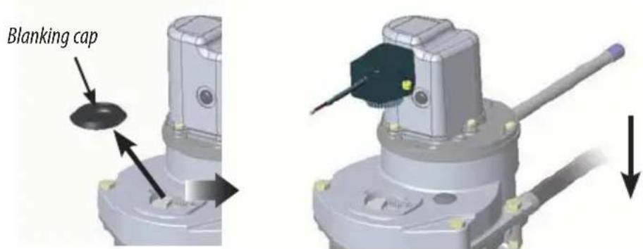
Installing the rudder feedback unit
3
Electrical installation
Connecting drive to autopilot

flowchart
graph TD
    A["Engine"] --> B["F100"]
    B --> C["SOL-MOTOR"]
    C --> D["SOLGND"]
    D --> E["DRIVE ENGAGE"]
    E --> F["Rudder"]
    F --> G["LAMP"]
    F --> H["STBD"]
    F --> I["PORT"]
    F --> J["GND"]
    F --> K["REMOTE"]
    F --> L["ALARM"]
    L --> M["NET-S"]
    L --> N["NET-C"]
    L --> O["NET-H"]
    L --> P["NET-L"]
    L --> Q["SPARE"]
    F --> R["BRIDGE"]
    F --> S["BRIDGE"]
    F --> T["BRIDGE"]
    F --> U["BRIDGE"]
    F --> V["BRIDGE"]
    F --> W["BRIDGE"]
    F --> X["BRIDGE"]
    F --> Y["BRIDGE"]
    F --> Z["BRIDGE"]
    style A fill:#f9f,stroke:#333
    style F fill:#ccf,stroke:#333
4
Accessories
 | 000-11497-001 | 90 degree Bezel mounting kit – for Type S Straight Shaft Drive |
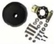 | 000-11498-001 | 20 degree Bezel mounting kit – for Type S Straight Shaft Drive |

SIMRAD
- Introduction
- Mechanical installation
- Electrical installation
- Accessories
- 1
- Introduction
- System overview
- Compatibility information
- Teleflex Safe T or Teleflex Big T Uflex T71, Uflex T73NR or Uflex T81
- Compliance statements
- General maintenance guide
- Important safety features
- Manual release
- To disengage the drive
- Dockside testing
- Manual override
- 2
- Mechanical installation
- Available space - Physical Envelope & Orientation
- Cable compatibility
- Morse 304411-xxx or Telefl ex SSC52-xx (x = length in feet)
- Telefl ex SSC61-xx or Telefl ex SSC62-xx (x = length in feet)
- Ufl ex M66-xx (x = length in feet)
- Morse 304415-xxx, Telefl ex SSC72-xx or Ufl ex M47-xx (x = length in ft)
- Type S Straight Shaft Drive
- Mounting kits
- 90° Bezel kit 000-11497-001
- 20° Bezel kit 000-11498-001
- Fitting the drive unit
- Replacing steering cable
- Cable length calculation
- Running new steering cable
- Rudder Feedback unit (RFB) installation and calibration
- 3
- Electrical installation
- Connecting drive to autopilot
- 4
- Accessories
- SIMRAD
Brand : SIMRAD
Model : Straight Shaft Helm Drive
Category : Commande de direction bateau