SUN-25K-G04-LV - Solar installation Deye - Free user manual and instructions
Find the device manual for free SUN-25K-G04-LV Deye in PDF.


| Product Type | Grid-Tie Solar Inverter |
| Brand | Deye |
| Model | SUN-25K-G04-LV |
| Rated Output Power | 25 kW |
| Max. Input Voltage | 1000 VDC |
| MPPT Voltage Range | 200 - 850 VDC |
| Number of MPP Trackers | 2 |
| Output Type | Three-Phase, Low Voltage (400 VAC) |
| Max. Efficiency | 98.6% |
| European Efficiency | 98.0% |
| Dimensions (W x H x D) | 690 x 510 x 280 mm |
| Weight | 50 kg |
| Cooling | Smart Fan Cooling |
| IP Rating | IP65 |
| Operating Temperature Range | -25°C to +60°C |
| Communication | RS485, Optional Wi-Fi |
| Display | LCD |
| Warranty | 5 Years (Standard) |
| Safety Features | Anti-Islanding, Overvoltage, Overcurrent, Ground Fault Protection |
| Maintenance | Clean air vents and check connections every 6 months |
| Reparability | Replacement parts available; authorized service centers |
Frequently Asked Questions - SUN-25K-G04-LV Deye
User questions about SUN-25K-G04-LV Deye
0 question about this device. Answer the ones you know or ask your own.
Ask a new question about this device
Download the instructions for your Solar installation in PDF format for free! Find your manual SUN-25K-G04-LV - Deye and take your electronic device back in hand. On this page are published all the documents necessary for the use of your device. SUN-25K-G04-LV by Deye.
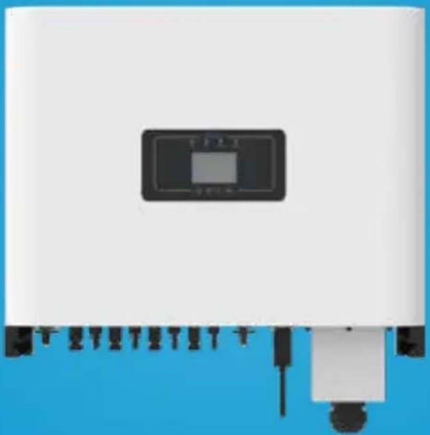
USER MANUAL SUN-25K-G04-LV Deye
Grid-connected PV Inverter
SUN-25K-G02-LV
SUN-30K-G02-LV
User Manual
natural_image
White industrial machine with a control panel and mechanical components, set against a blue background (no visible text or symbols)Contents
1. Introduction - 1 -
1.1 Appearance Introduction - 1 -
1.2 Parts list - 2 -
2. Safety warnings and instructions ..... - 3 - ....
2.1 Safety signs -3-
2.2 Safety instructions -3-
2.3 Notes for using -4-
3. Operation Interface -5-
3.1 Interface View -5-
3.2 Status Indicator -5-
3.3 Buttons - 6 -
3.4 LCD Display -6-
4. Product installation -7-
4.1 Select installation location -7-
4.2 Mounting bracket of inverter -9-
4.3 Inverter Installation - 10 -
5. Electrical Connection ...... - 11 -
5.1 PV Module Selection - 11 -
5.2 DC input terminal connection - 13 -
5.3 AC input terminal connection - 16 -
5.4 The connection of the ground line - 16 -
6. Startup and Shutdown - 18 -
6.1 Start up the inverter - 18 -
6.2 Inverter Shutdown - 18-
7. Zero-export function via energy meter - 19 -
7.1 Multiple strings and parallel connection meters - 29 -
7.2 How to browse the load power of your PV grid-tieplant on monitoring platform? - 39 -
8. General Operation - 41 -
8.1 The initial interface - 44 -
8.2 Statistics information - 46 -
8.3 Fault Record - 48 -
8.4 ON/OFF setting - 49 -
9. Repair and Maintenance -69-
10. Error information and processing -69-
- Specification -74-
- EU Declaration of Conformity - 75 -
About This Manual
The manual mainly describes the product information, guidelines for installation, operation and maintenance. The manual cannot include complete information about the photovoltaic (PV) system.
How to Use This Manual
Read the manual and other related documents before performing any operation on the inverter. Documents must be stored carefully and be available at all times. Contents may be periodically updated or revised due to product development. The information in this manual is subject to change without notice. The latest manual can be acquired via service@deye.com.cn
1. Introduction
1.1 Appearance Introduction
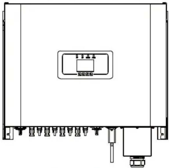
On-grid inverter can convert solar panel DC power into AC power which can directly input to the grid. Its appearance is shown below. These models contain SUN-25K-G02-LV, SUN-30K-G02-LV. The following is collectively referred to as “inverter”.
natural_image
Technical line drawing of a mechanical or electrical enclosure with no visible text or symbolsPic 1.1 Front view
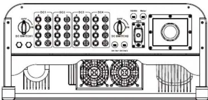
Pic 1.2 Bottom view
1.2 Parts list
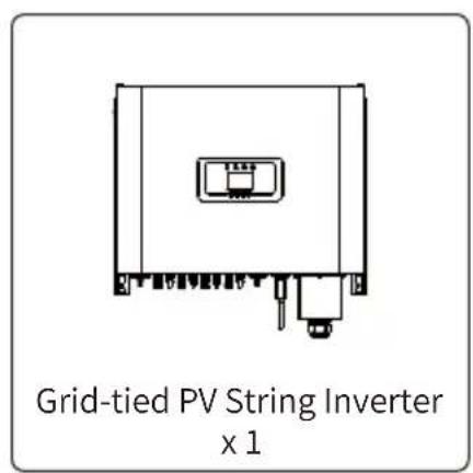
Please check the following table, to see whether all the parts are included in the package:
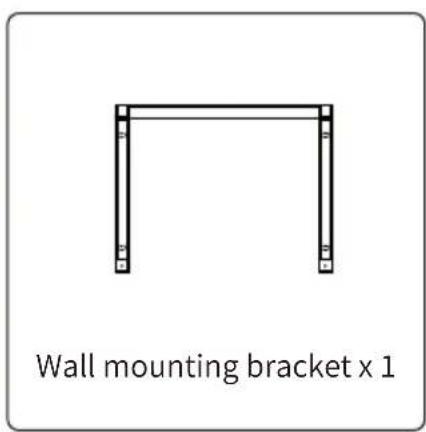
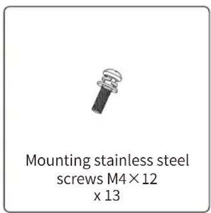
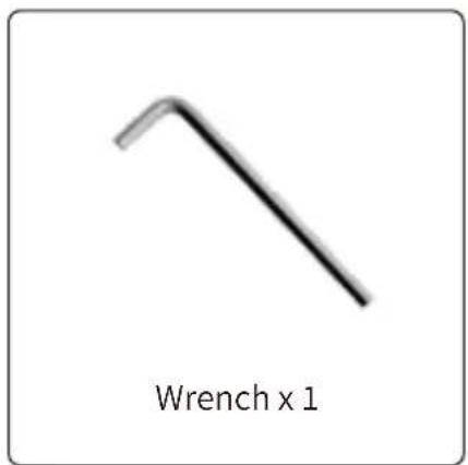
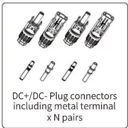
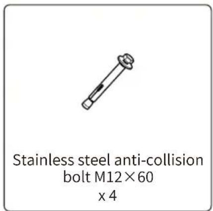
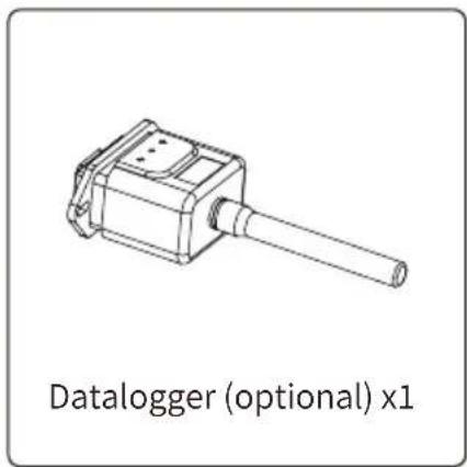
natural_image
Technical line drawing of a mechanical device with a cylindrical shaft and housing (no text or symbols on the diagram itself)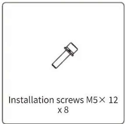
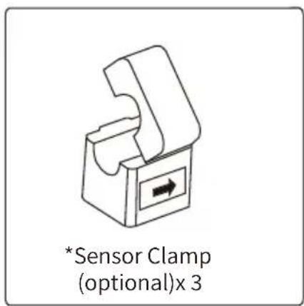
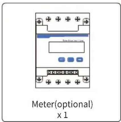
2. Safety warnings and instructions
Improper use may result in potential electric shock hazards or burns. This manual contains important instructions that should be followed during installation and maintenance. Please read these instructions carefully before use and keep them for future reference.
2.1 Safety signs
Safety symbols used in this manual, which highlight potential safety risks and important safety information, are listed as follows:

Warning:
Warning symbol indicates important safety instructions, which if not correctly followed, could result in serious injury or death.
Shock Hazard:
Caution, risk of electric shock symbol indicates important safety instructions, which if not correctly followed, could result in electric shock.

Safety Hint:
Note symbol indicates important safety instructions, which if not correctly followed, could result in some damage or the destruction of the inverter.

High Temperature Hazard:
Caution, hot surface symbol indicates safety instructions, which if not correctly followed, could result in burns.
2.2 Safety instructions

Warning:
Electrical installation of the inverter must conform to the safety operation rules of the country or local area.

Warning:
Inverter adopts non-isolated topology structure, hence must insure DC input and AC output are electrical isolated before operating the inverter.
Shock Hazard:
Prohibit disassembling inverter case, there existing shock hazard, which may cause serious injury or death, please ask qualified person to repair.
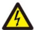
Shock Hazard:
When PV module is exposed to sunlight, the output will generate DC voltage. Prohibit touching to avoid shock hazard.
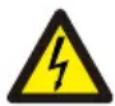
Shock Hazard:
While disconnect the input and output of the inverter for maintenance, please waits for at least 5 mins until the inverter discharge the remnant electricity.
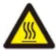
High Temperature Hazard:
Local temperature of inverter may exceed 80^ C while under operating. Please do not touch the inverter case.
2.3 Notes for using
The three phase string power inverter is designed and tested under related safety regulations. It can ensure the personal safety of the user. But as a electric device, it may cause shock or injury by incorrect operation. Please operate the unit under below requirements:
- Inverter should be installed and maintained by qualified person under local standard regulations.
- Must disconnect the AC side first, then disconnect DC side while doing installation and maintenance, after that, please wait at least 5 mins to avoid getting shocked.
- Local temperature of the inverter may exceed 80 °C while under operating. Do not touch to avoid getting injured.
- All electrical installation must be in accordance with local electrical standards, and achieved permission of local power company.
- Please take appropriate anti-static measure.
- Please install where children can not touch.
3. Operation Interface
3.1 Interface View
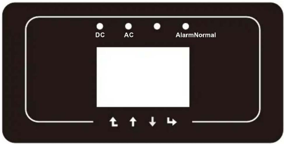
Pic 3.1 Front panel display
3.2 Status Indicator
The inverter panel has 4 indicators, the left one is dc output indicators, green indicates normal DC input. Beside is the AC indicator, green indicating normal ac connection. Beside the AC indicator is the operating indicator, green indicating normal output. The right indicator is alarm. red indicates alarming.
| Indicator status | Explanation | |
| DC | on | Inverter detects DC input |
| off | Low DC input voltage | |
| AC | on | Grid Connected |
| off | Grid Unavailable | |
| NORMAL | on | Under normal operating |
| off | Stop operating | |
| ALARM | on | Detected faults or report faults |
| off | Under normal operating | |
Table 3.1 Status indicator lights
3.3 Buttons
There are four buttons on the inverter panel: Above is Up and increase button(UP), Below is down and decrease button(DOWN), Left is ESC button(ESC), Right is Enter button(ENTER). Achieving below functions by the four buttons:
- Page turning (use UP and DOWN button)
- Modify adjustable parameters (use ESC and ENTER button)
3.4 LCD Display
Three phase string inverter use 256*128 dot formation display, Display below content:
- Inverter operation status and information;
- Operating information;
- Warning message and malfunction display.
4. Product installation
4.1 Select installation location
To select a location for the inverter, the following criteria should be considered:
WARNING: Risk of fire
- Do not install the inverter in areas containing highly flammable materials or gases.
- Do not install the inverter in potentially explosive atmospheres.
- Do not install in small closed spaces where air can not circulate freely. To avoid overheating,
always make sure the flow of air around the inverter is not blocked.
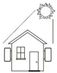
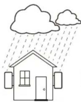
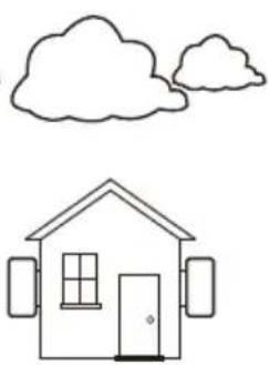
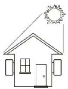
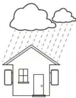
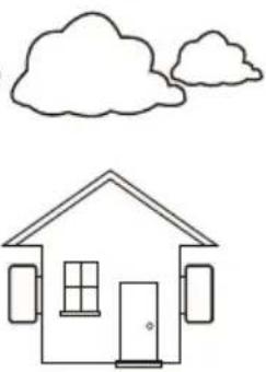
- Exposure to direct sunlight will increase the operational temperature of the inverter and may cause output power limiting. It is recommended that inverter installed to avoid direct sunlight or raining.
- To avoid overheating ambient air temperature must be considered when choosing the inverter installation location. It is recommended that using a sun shade minimizing direct sunlight when the ambient air temperature around the unit exceeds 104^ / 40^ .
natural_image
Simple line drawing of a house with sun and roof, no text or symbols present×
natural_image
Simple line drawing of a house under rain with cloud and raindrops (no text or symbols)×
natural_image
Simple line drawing of a house with cloud above and door, no text or symbols present×
natural_image
Simple line drawing of a house with sun and roof, no text or symbols present√
natural_image
Simple line drawing of a house under rain with cloud and raindrops (no text or symbols)√
natural_image
Simple line drawing of a house with cloud above and door, no text or symbols present√
Pic 4.1 Recommended installation place
• Install on a wall or strong structure capable of bearing the weight.
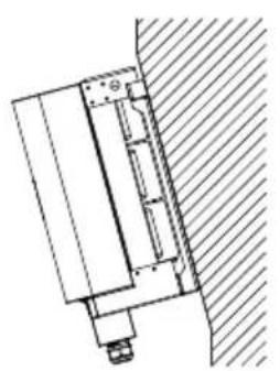
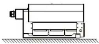
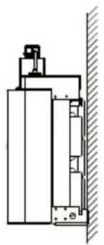
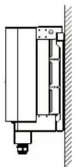
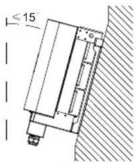
- Install vertically with a maximum incline of +/-15^ . If the mounted inverter is tilted to an angle greater than the maximum noted, heat dissipation can be inhibited, and may result in less than expected output power.
- If install more than one inverter, must leave at least 500mm gap between each inverter. And each inverter must be at least 500mm above and below. And must install the inverter at the place where children cannot touch. Please see picture 4.3.
- Consider whether the installation environment is helpful to see the inverter LCD display and indicator status clearly.
- Must offer a ventilate environment if inverter installed in the airtight house.

Safety Hint:
Do not place or store any items next to the inverter.
natural_image
Technical line drawing of a mechanical assembly with no visible text or symbols×
natural_image
Technical line drawing of a mechanical device with no visible text or symbols×
natural_image
Technical line drawing of a mechanical assembly or enclosure with no visible text or symbols×
natural_image
Technical line drawing of a mechanical assembly with no visible text or symbols√
√
Pic 4.2 Installation Angle
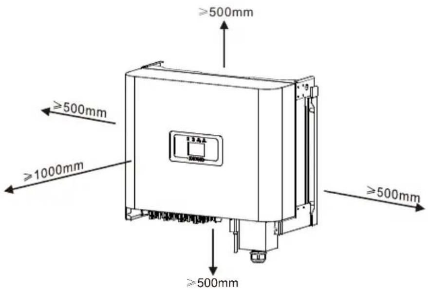
Pic 4.3 Installation Gap
4.2 Mounting bracket of inverter
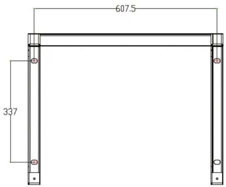
Pic 4.4 Mounting bracket dimensions
4.3 Inverter Installation
The inverter should be mounted in a vertical position. The steps of mounting are as follows
- For brick walls, the position of the holes should be suitable for the expansion bolts.
- Make sure the bracket is horizontal and the mounting holes are in the correct points. Drilling the holes on the wall according the marks.
- Using the expansion bolts to fix the bracket to the wall.
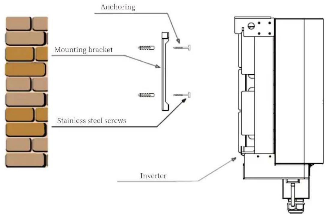
Pic 4.5 Inverter Installation
5 Electrical Connection
5.1 DC input terminal connection
- Switch the Grid Supply Main Switch(AC)OFF.
- Switch the DC Isolator OFF.
- Assemble PV input connector to the inverter.

Warning:
When using PV modules, please ensure the PV+ & PV- of solar panel is not connected to the system ground bar.

Safety Hint:
Before connection, please make sure the polarity of the output voltage of PV array matches the “DC+” and “DC-” symbols.

Warning:
Before connecting inverter, please make sure the PV array open circuit voltage is within the 800V of the inverter.
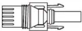
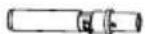
Pic 5.1 DC+ male connector
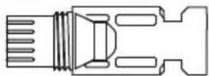
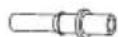
Pic 5.2 DC- female connector

Safety Hint:
Please use approved DC cable for PV system.
| Cable type | Cross section (mm2) | |
| Range Recommended | ded value | |
| Industry generic PV cable (model: PV1-F) | 4.0~6.0(12~10AWG) | 4.0(12AWG) |
Table 5.1 DC Cable Specifications
The steps to assemble the DC connectors are listed as follows:
a) Strip off the DC wire about 7mm, disassemble the connector cap nut (see picture 5.3).
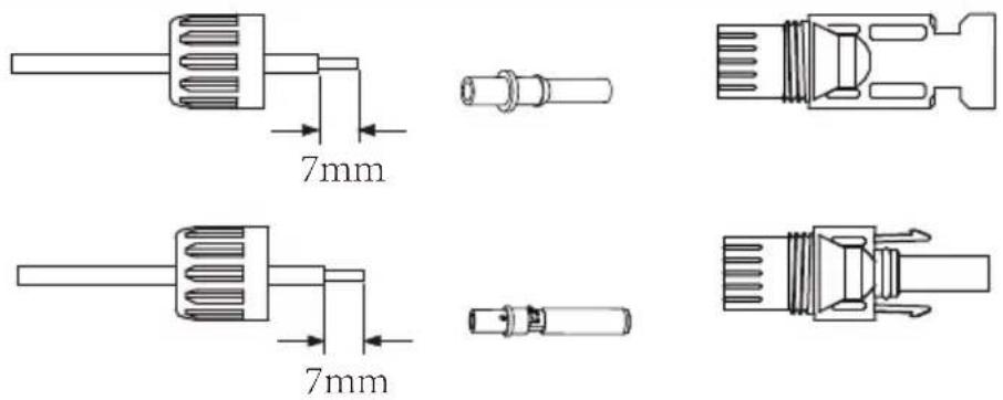
Pic 5.3 Disassemble the connector cap nut
b) Crimping metal terminals with crimping pliers as shown in picture 5.4.
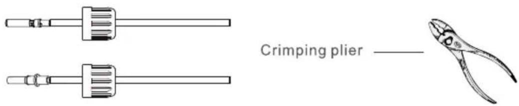
Pic 5.4 Crimp the contact pin to the wire
c) Insert the contact pin to the top part of the connector and screw up the cap nut to the top part of the connector. (as shown in picture 5.5).
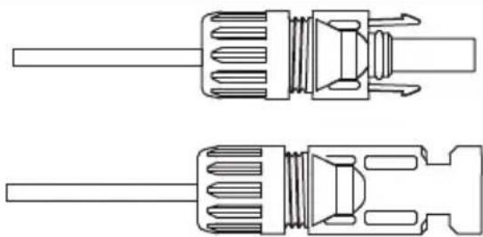
natural_image
Technical line drawing of two mechanical components with threaded ends and shafts (no text or symbols)Pic 5.5 connector with cap nut screwed on
d) Finally insert the DC connector into the positive and negative input of the inverter, shown as picture 5.6
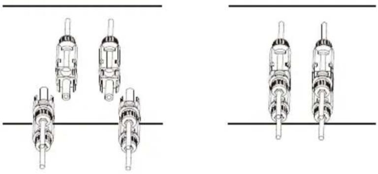
natural_image
Technical line drawings of mechanical components with no visible text or symbolsPic 5.6 DC input connection

Warning:
Sunlight shines on the panel will generate voltage, high voltage in series may cause danger to life. Therefore, before connecting the DC input line, the solar panel needs to be blocked by the opaque material and the DC switch should be 'OFF', otherwise, the high voltage of the inverter may lead to life-threatening conditions.

Warning:
Please use its own DC power connector from the inverter accessories. Do not interconnect the connectors of different manufacturers.Max. DC input current should be 20A. if exceeds, it may damage the inverter and it is not covered by Deye warranty.
5.2 AC terminal connection
| Model | Wire Size | Cable( mm^2 ) | Torque value(max) Max | cable length |
| 25/30kW 12.4Nm | 4AWG | 21mm^2 | Outside cable (3L+N)20m |
Table 5.2 Recommended cable specifications

Warning:
The AC cable line L1 is connected to socket 1; L2 is connected to socket 2; L3 is connected to socket 3, the PE line is connected to the earth, the N wire is connected to the socket of N.
AC wire production method is the same as that of 5.2.1.
AC wire installation method:
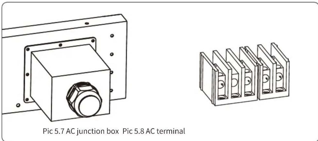
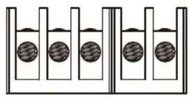
1) Remove the 8 fixing screws on the AC junction box of the inverter as shown in Pic 5.7. After removing the junction box, you can see the terminals of the inverter. The default is 4 digits as shown in Pic 5.8.
2) Connect the cable through the junction box, waterproof jacket, and insert into the terminal (The picture Pic 5.9 shows the connection mode of three phase lines connected to the junction box, ground wire screwed on the inverter shell), and use hexagon screwdriver to presses the wiring harness to the connect terminal as shown in Pic 5.10.
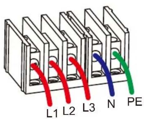
Pic 5.9 AC cable connected to the terminal
natural_image
Diagram of a test tube with four wells containing water, no text or symbols presentPic 5.10 Tightening the AC connection cable
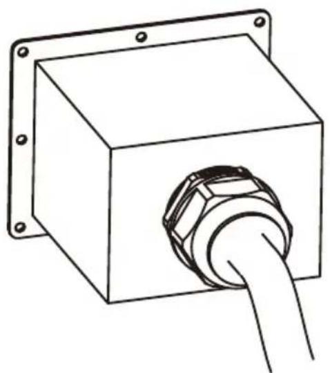
3) Screw the AC connection cover back to the shell and tighten all the screws to tighten the waterproof protection connector, as shown in Pic 5.11
natural_image
Line drawing of a rectangular electrical connector with a bulb inserted, mounted on a mounting bracket (no text or symbols)Pic 5.11 Tighten the AC junction box
5.2.3 Recommended current protector specifications
| Inverter | Rated voltage | Rated output power (KW) | Current protection device (A) |
| SUN-25K-G02-LV | 127 | 25 | 75 |
| SUN-30K-G02-LV | 127 | 30 | 90 |
Table 5.3 Recommended current protector specifications
5.3 Connection of the ground line
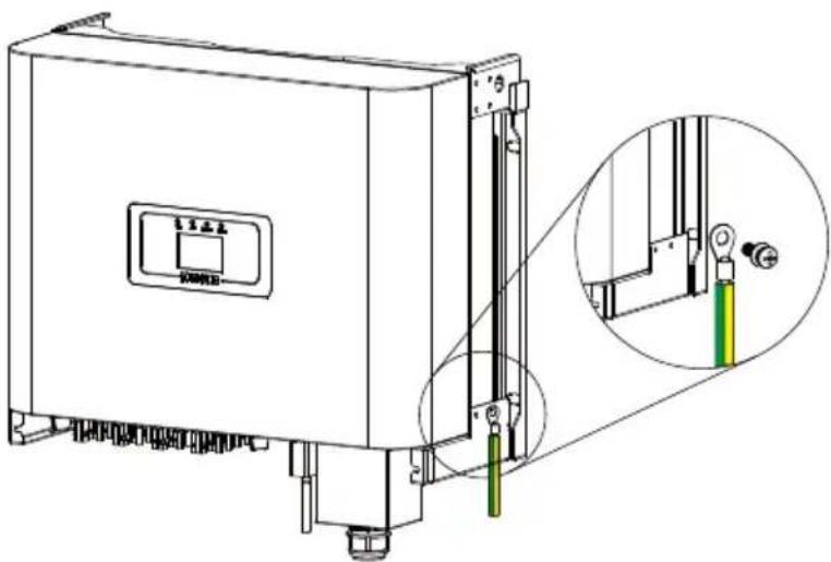
Good grounded is important for resist the surge voltage shock and improve EMI's performance. So before the connection of AC, DC, communication connections, inverter needs to ground first. For a single system, just ground the PE cable; For multiple machine systems, all PE cables of the inverter need to be connected to the same grounding copper platoon to ensure the equipotent connection. The installation of the shell ground wire is shown as Pic 5.12.
natural_image
Technical line drawing of a mechanical device with a close-up inset showing internal components (no text or symbols)Pic 5.12 The installation of the shell ground wire
| Model | Wire Size | Cable( mm^2 ) | Torque value(max) |
| 25/30kW 12.4Nm | 5AWG | 16.7mm^2 |

Warning:
Inverter has built-in leakage current detection circuit, If an external leakage current protection device is connected, its operating current must be greater than 300 mA or higher, otherwise inverter may not work properly.
5.4 Inverter monitoring connection
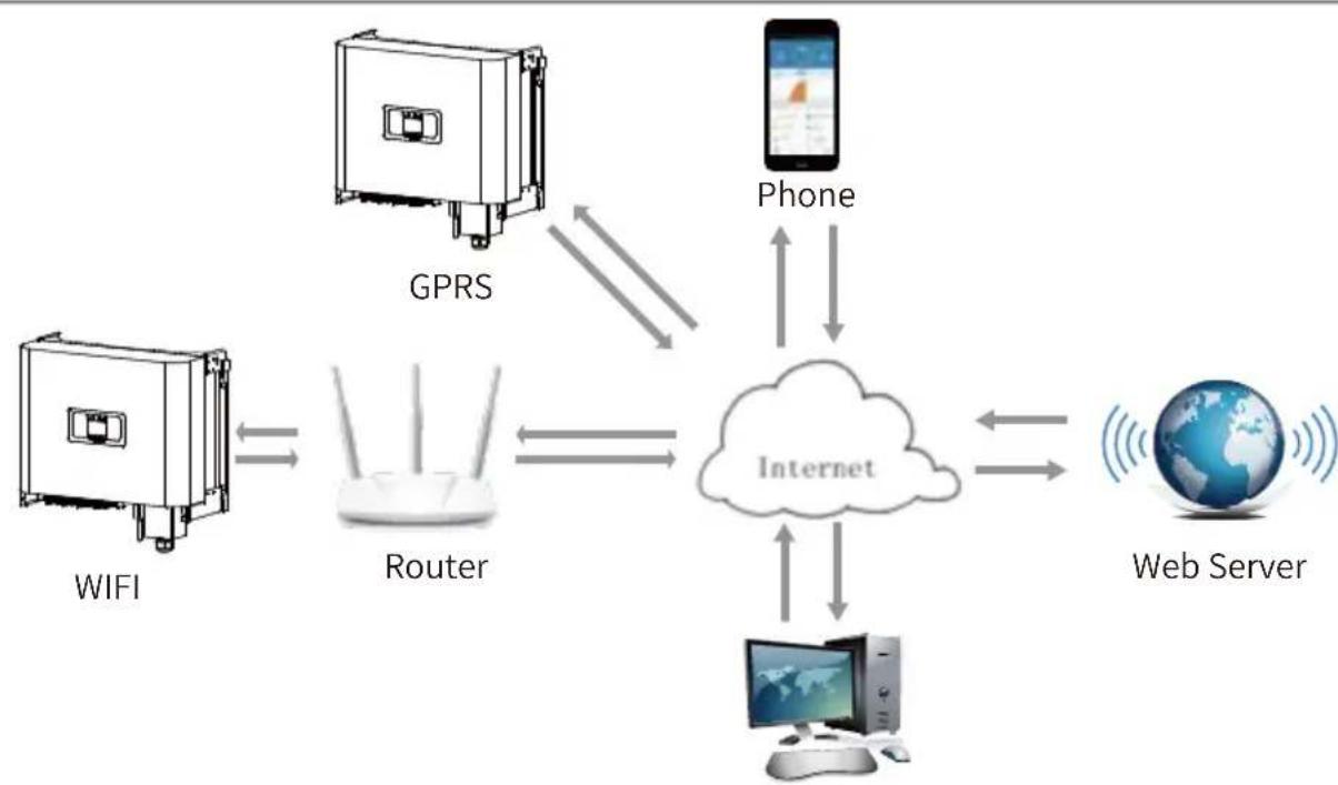
Inverter has the function of wireless remote monitoring inverter. The inverter has Wifi function and Wifi Plug in the accessories is used to realize the connection between the inverter and the network. The operation, installation, networking, APP download are detailed in the WIFI PLUG instructions. Figure 5.13 is the Internet monitoring solution.
flowchart
graph TD
    A["WIFI"] <--> B["Router"]
    C["GPRS"] <--> D["Internet"]
    E["Phone"] <--> D
    F["Web Server"] <--> D
    B <--> D
    D <--> E
    B <--> F
    C <--> D
Pic 5.13 Internet monitoring solution
5.4.1 Installation of datalogger
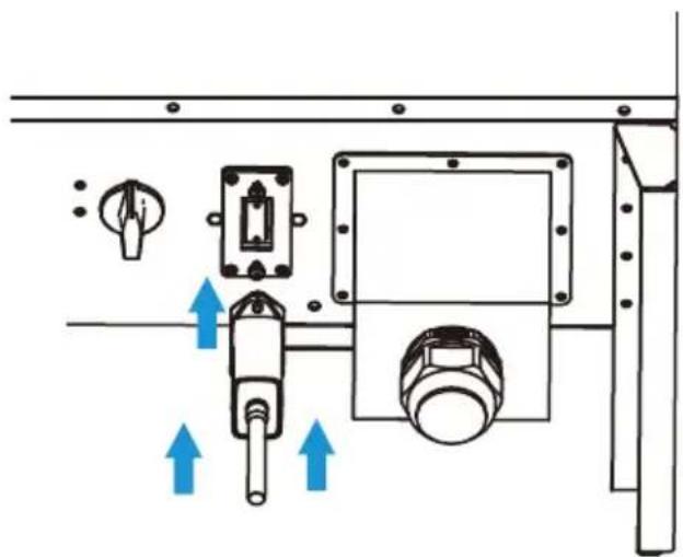
When installing the WiFi stick, tear off the sealing strip on the inverter. Insert the datalogger into the interface and fix it with a screw. The configuration of the datalogger needs to be performed after various electrical connections have been completed and the inverter DC power on. When the inverter is on the DC power, it is determined whether the datalogger is normally electrified (The LED light shines out of the shell).
natural_image
Technical diagram of a mechanical assembly with directional arrows and component labels (no readable text or symbols)Pic 5.14 datalogger installation diagram
5.4.2 Configuration of datalogger
For the configuration of datalogger, please refer to illustrations of the datalogger.
6. Start up and Shut off
Ensure that the inverter meets the following conditions before starting the inverter, otherwise it may cause fire or damage to the inverter without quality assurance, at the same time the situation on our company does not undertake any responsibility. At the same time, to optimize the system configuration, it is recommended that the two inputs be connected to the same number of PV modules.
a). The maximum open circuit voltage of each set of PV modules shall not exceed 1000Vdc under any conditions.
b). Each input of the inverter better use the same type of PV module in series.
c). Total output power of PV shall not exceed the maximum input power of inverter, each PV modules shall not exceed the rated power of each channel.
6.1 Start up the inverter
When starting up the inverter, should fellow steps below:
- Starting switch on the AC breaker.
- Turn on the DC switch of the PV module, and if the panel provides sufficient starting voltage and power, the inverter will start.
- The inverter will first check the internal parameters and the grid parameters, while the liquid crystal will show that the inverter is self-checking.
- If the parameter is within acceptable range, the inverter will generate energy. NORMAL indicator light is on.
6.2 Shut off the inverter
Must follow below steps while Shutting down the inverter:
- Switch off the AC breaker.
- Wait for 30 seconds, turn off the dc switch (if any), or simply disconnect the dc input connector. The inverter will close the LCD and all led within two minutes.
7. Zero-export function via energy meter
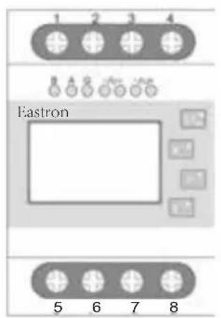
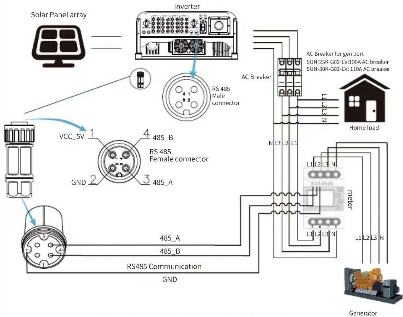
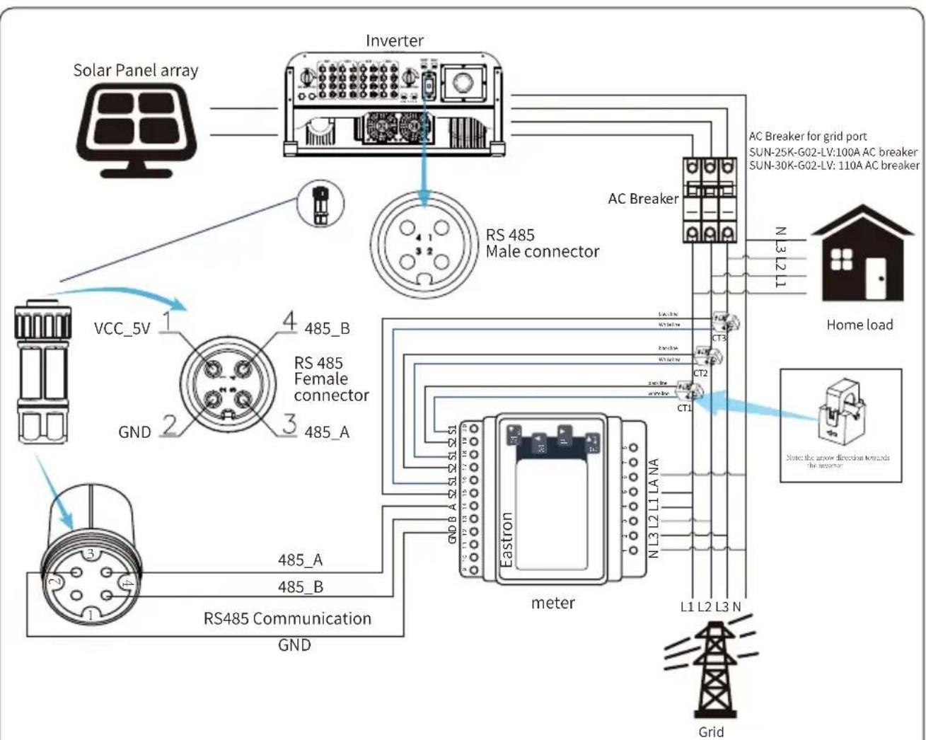
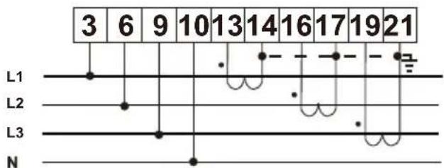
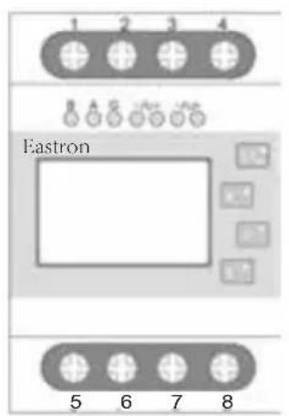
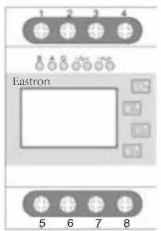
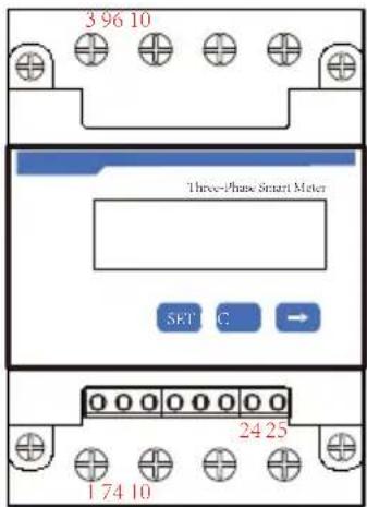
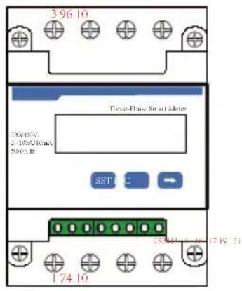
There're four kinds of energy meters for this series inverter. First type is Eastron SDM630-Modbus V2 which is able to measure the Max. 100A current directly. More details please refer to Pic 7.1 & 7.4. For the Eastron SDM630 MCT 40mA, it needs external CT to measure the current. The CT power range is from 5A-2000A. More details about the Eastron SDM630 MCT, please refer to Pic 7.5 & 7.8. Also, the CHNT meter DTSU666 is supported, it can measure the Max. 80A current directly. More details about the DTSU666, please refer to Pic 7.9 - 7.16.
When you are reading this, we believe that you have completed the connection according to the requirements of chapter 5, if you have been running your inverter at this time, and you want to use the zero-export function, please turn off AC and DC switch of the inverter, and wait for 5 minutes until the inverter completely discharged.
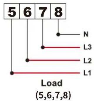
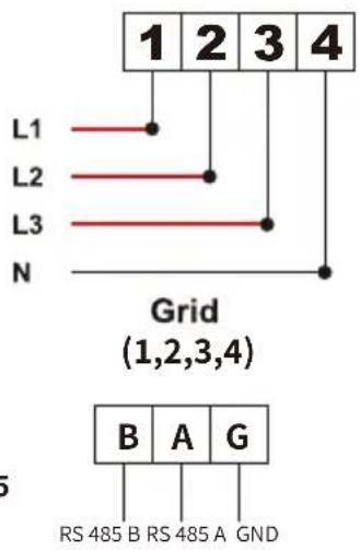
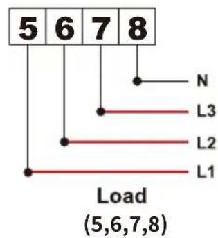
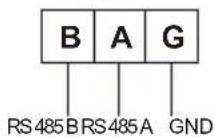
For system wiring diagram, the red line refers to L line (L1, L2, L3), the black line refers to the neutral line (N). Connecting energy meter RS485 cable to inverter's RS485 port. It's recommended to install an AC switch between the inverter and the utility grid, the specs of the AC switch are determined by the power of load.
If there is no integrated DC switch inside the inverter you purchased, we commend you to connect the DC switch. The voltage and current of the switch depend on the PV array you access.
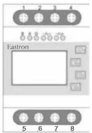
Eastron SDM630-Modbus V2
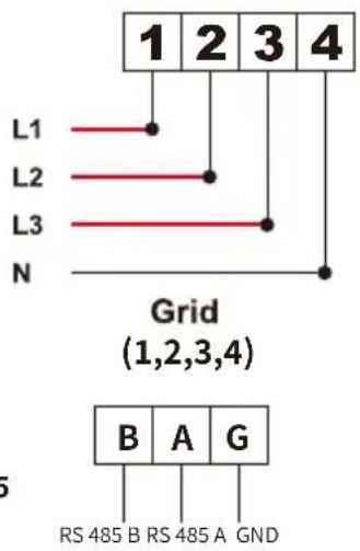
RS 485
Pic 7.1 Eastron meter
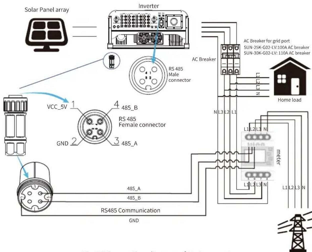
Pic 7.2 Connection diagram of Eastron meter

Warning:
In final installation, breaker certified according to IEC 60947-1 and IEC 60947-2 shall be installed with the equipment.
Eastron SDM630-Modbus V2
RS 485
Pic 7.3 Eastron meter
flowchart
graph TD
    A["Solar Panel array"] --> B["Inverter"]
    B --> C["RS 485 Male connector"]
    C --> D["AC Breaker"]
    D --> E["Home load"]
    E --> F["meter"]
    F --> G["Generator"]
    B --> H["VCC_5V 1"]
    B --> I["GND 2"]
    B --> J["RS 485 Female connector"]
    J --> K["RS485 Communication GND"]
    K --> L["AC Breaker for gen port SUN-25K-G02-LV:100A AC breaker SUN-30K-G02-LV:110A AC breaker"]
    style A fill:#f9f,stroke:#333
    style B fill:#ccf,stroke:#333
    style C fill:#cfc,stroke:#333
    style D fill:#fcc,stroke:#333
    style E fill:#ffc,stroke:#333
    style F fill:#fcc,stroke:#333
    style G fill:#fff,stroke:#333
    style H fill:#fff,stroke:#333
    style I fill:#fff,stroke:#333
    style J fill:#fff,stroke:#333
    style K fill:#fff,stroke:#333
    style L fill:#fff,stroke:#333
Pic 7.4 Connection diagram of Eastron meter
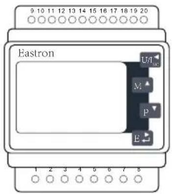
Eastron SDM630MCT
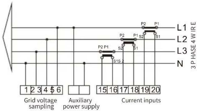
flowchart
graph TD
    A["Grid voltage sampling"] --> B["Auxiliary power supply"]
    B --> C["Current inputs"]
    subgraph Grid voltage sampling
        D["1"] --> E["2"] --> F["3"] --> G["4"] --> H["$6"]
    end
    subgraph Auxiliary power supply
        I["15"] --> J["16"] --> K["17"] --> L["18"] --> M["19"] --> N["20"]
    end
    subgraph Current inputs
        O["P2"] --> P["P1"]
        Q["S1"] --> R["S2"]
        S["S1S"] --> T["S2"]
        U["P1"] --> V["P2"]
        W["P2"] --> X["P1"]
        Y["S1"] --> Z["S2"]
        AA["P1"] --> AB["S2"]
        AC["S1S"] --> AD["S2"]
        AE["P1"] --> AF["S1"]
        AG["P2"] --> AH["S2"]
        AI["S1"] --> AJ["S2"]
        AK["P1"] --> AL["S1"]
        AM["P2"] --> AN["S2"]
        AO["S1S"] --> AP["S2"]
        AQ["P1"] --> AR["S1"]
        AS["P2"] --> AT["S2"]
        AU["S1"] --> AV["S2"]
        AW["P1"] --> AX["S1"]
        AY["P2"] --> AZ["S2"]
        BA["P2"] --> BB["S1"]
        BC["P1"] --> BD["S1"]
        BE["P2"] --> BF["S2"]
        BG["P1"] --> BH["S1"]
        BI["P2"] --> BJ["S2"]
        BK["P1"] --> BL["S1"]
        BM["P2"] --> BN["S2"]
        BO["P1"] --> BP["S1"]
        BQ["P2"] --> BR["S2"]
        BS["P1"] --> BT["S1"]
        BU["P2"] --> BV["S2"]
        BW["P1"] --> BX["S1"]
        BY["P2"] --> BZ["S2"]
        CA["P1"] --> CB["S1"]
        CC["P2"] --> CD["S2"]
        DE["P1"] --> DF["S1"]
        DG["P2"] --> DH["S2"]
        DI["P1"] --> DJ["S1"]
        DK["P2"] --> DL["S2"]
        DM["P1"] --> DJ
        MX["P2"] --> DY["S1"]
        DX["P1"] --> DY
        DY --> DX
    end
RS 485
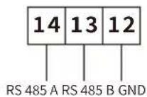
Pic 7.5 Eastron meter
flowchart
graph TD
    A["Solar Panel array"] --> B["Inverter"]
    B --> C["RS 485 Male connector"]
    C --> D["AC Breaker"]
    D --> E["Home load"]
    E --> F["Grid"]
    G["VCC_5V"] --> H["RS 485 Female connector"]
    H --> I["RS485 Communication"]
    I --> J["Grid"]
    K["AC Breaker for grid port"] --> L["SUN-25K-G02-LV:100A AC breaker"]
    K --> M["SUN-30K-G02-LV: 110A AC breaker"]
    N["Home load"] --> O["Refering direction towards the inverter"]
    P["Grid"] --> Q["L1 L2 L3 N"]
Pic 7.6 Connection diagram of Eastron meter
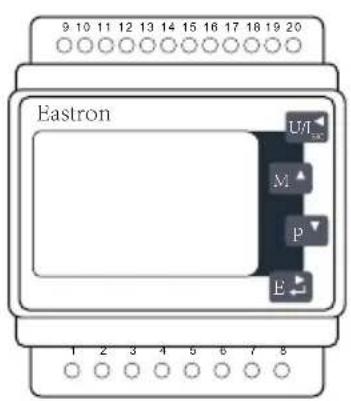
Eastron SDM630MCT
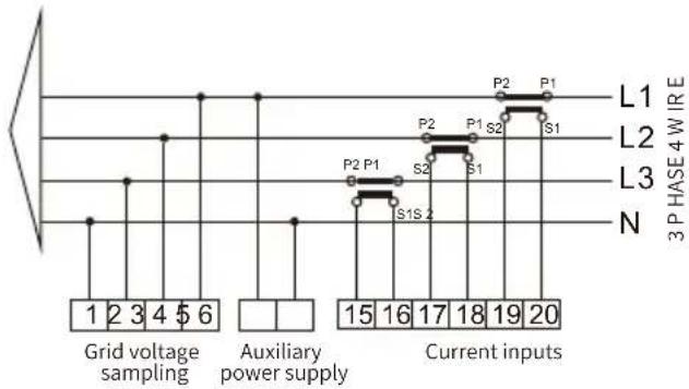
flowchart
graph TD
    A["Grid voltage sampling"] --> B["Auxiliary power supply"]
    B --> C["Current inputs"]
    subgraph Grid voltage sampling
        D["1"] --> E["2"] --> F["3"] --> G["4"] --> H["$6"]
    end
    subgraph Auxiliary power supply
        I["15"] --> J["16"] --> K["17"] --> L["18"] --> M["19"] --> N["20"]
    end
    subgraph Current inputs
        O["P2"] --> P["P1"]
        Q["P1"] --> R["S1"]
        S["P2"] --> T["S2"]
        U["P1"] --> V["S1S"]
        W["P1"] --> X["S1"]
        Y["P2"] --> Z["S2"]
        AA["P1"] --> AB["S1S"]
        AC["P2"] --> AD["S2"]
        AE["P1"] --> AF["S1"]
        AG["P2"] --> AH["S1S"]
    end
    style Grid voltage sampling fill:#f9f,stroke:#333
    style Auxiliary power supply fill:#ccf,stroke:#333
    style Current inputs fill:#cfc,stroke:#333
    style Grid voltage sampling fill:#fff,stroke:#333
    style Auxiliary power supply fill:#fff,stroke:#333
    style Current inputs fill:#fff,stroke:#333
RS 485
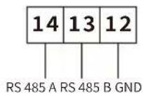
Pic 7.7 Eastron meter
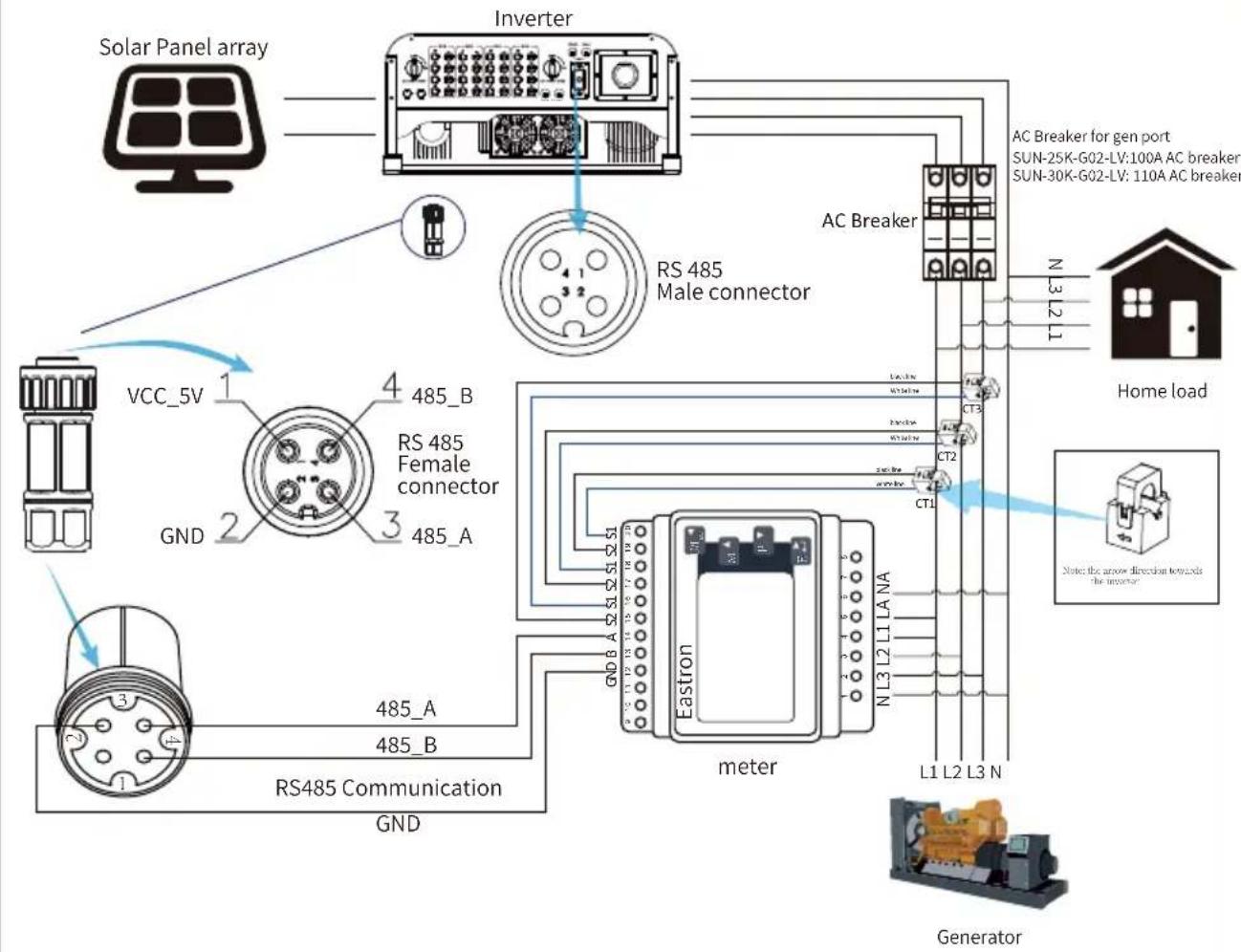
flowchart
graph TD
    A["Solar Panel array"] --> B["Inverter"]
    B --> C["RS 485 Male connector"]
    C --> D["AC Breaker"]
    D --> E["Home load"]
    E --> F["Generator"]
    subgraph Inverter
        G["VCC_5V 1"]
        H["GND 2"]
        I["RS 485 Female connector 3"]
        J["RS485 Communication GND 1"]
    end
    subgraph Solar Panel Array
        K["Inverter"]
        L["RS 485 Female connector"]
    end
    M["AC Breaker for gen port"] --> N["SUN-25K-G02-LV:100A AC breaker"]
    M --> O["SUN-30K-G02-LV:110A AC breaker"]
    P["Home load"] --> Q["AC Breaker for gen port"]
    R["Generator"] --> S["AC Breaker for gen port"]
Pic 7.8 Connection diagram of Eastron meter
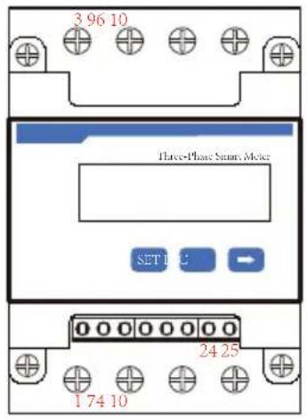
CHNT DTSU666
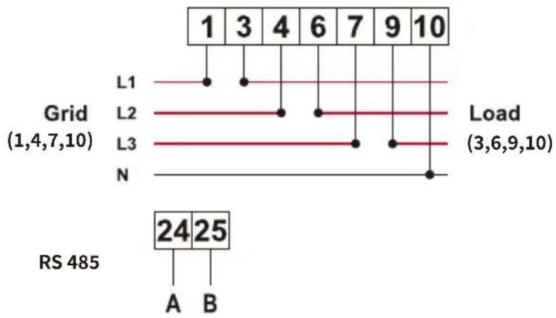
line
| Grid | Load | | :--- | :--- | | L1 | 1 | | L2 | 3 | | L3 | 4 | | N | 6 | | 1 | 7 | | 2 | 9 | | 3 | 10 | | 4 | 10 | | 5 | 10 | | 6 | 10 | | 7 | 10 | | 8 | 10 | | 9 | 10 | | 10 | 10 | | RS 485 | 24 |Pic 7.9 CHNT meter
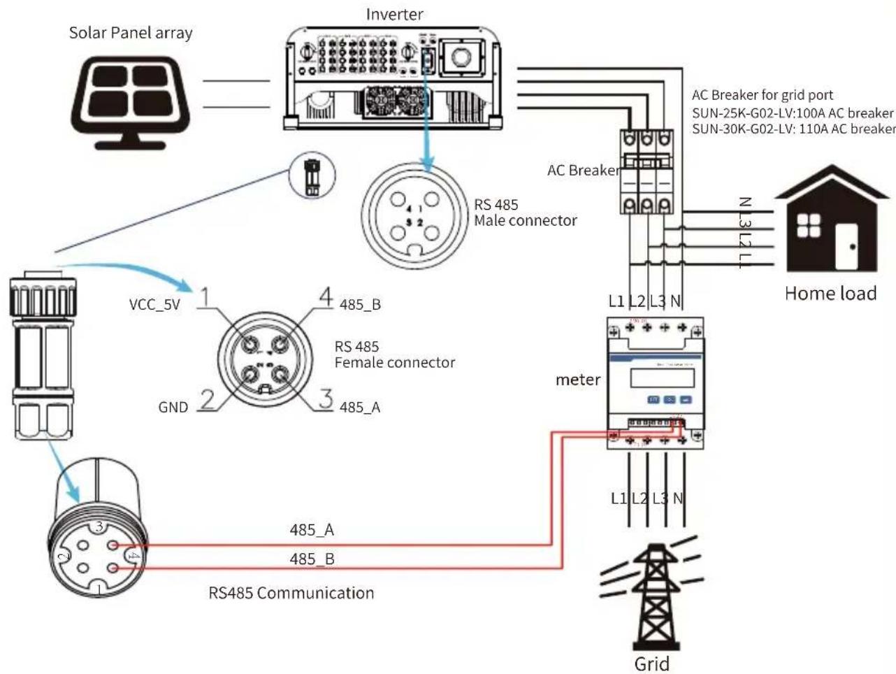
flowchart
graph TD
    A["Solar Panel array"] --> B["Inverter"]
    B --> C["RS 485 Male connector"]
    C --> D["AC Breaker for grid port"]
    D --> E["Home load"]
    E --> F["meter"]
    F --> G["Grid"]
    H["VCC_5V"] --> I["1"]
    I --> J["2"]
    J --> K["3"]
    K --> L["4"]
    L --> M["485_B"]
    N["GND"] --> O["1"]
    O --> P["2"]
    P --> Q["3"]
    Q --> R["485_A"]
    S["RS 485 Female connector"] --> T["1"]
    T --> U["2"]
    U --> V["3"]
    V --> W["485_B"]
    X["RS485 Communication"] --> Y["1"]
    Y --> Z["2"]
    Z --> AA["3"]
    AA --> AB["485_A"]
    AC["AC Breaker for grid port"] --> AD["SUN-25K-G02-LV:100A AC breaker"]
    AD --> AE["SUN-30K-G02-LV: 110A AC breaker"]
Pic 7.10 Connection diagram of CHNT meter
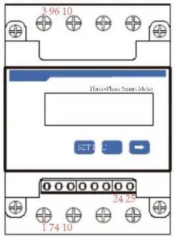
CHNT DTSU666
line
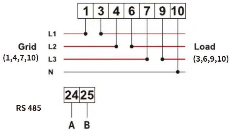
| Grid | Load | | :--- | :--- | | L1 | 1 | | L2 | 3 | | L3 | 4 | | N | 6 | | 1 | 7 | | 2 | 9 | | 3 | 10 | | 4 | 10 | | 5 | 10 | | 6 | 10 | | 7 | 10 | | 8 | 10 | | 9 | 10 | | 10 | 10 | | RS 485 | 24 |Pic 7.11 CHNT meter
flowchart
graph TD
    A["Solar Panel array"] --> B["Inverter"]
    B --> C["RS 485 Male connector"]
    C --> D["AC Breaker for gen port"]
    D --> E["SUN-25K-G02-LV:100A AC breaker"]
    D --> F["SUN-30K-G02-LV: 110A AC breaker"]
    G["Home load"] --> H["meter"]
    H --> I["Generator"]
    J["VCC_5V"] --> K["RS 485 Female connector"]
    K --> L["GND"]
    L --> M["RS485 Communication"]
    M --> N["485_A"]
    M --> O["485_B"]
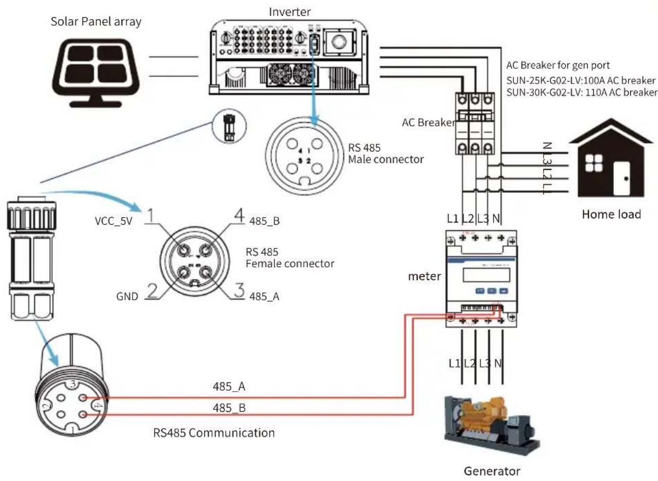
Pic 7.12 Connection diagram of CHNT meter
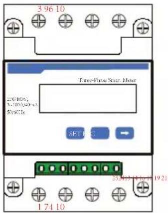
CHNT DTSU666
3x230/400V
100A/40mA
line
| Level | Value | |---|---| | L1 | 3 | | L1 | 6 | | L1 | 9 | | L1 | 10 | | L1 | 13 | | L1 | 14 | | L1 | 16 | | L1 | 17 | | L1 | 19 | | L1 | 21 | | L2 | | | L2 | | | L2 | | | L2 | | | L2 | | | L2 | | | L2 | | | L2 | | | L2 | | | L2 | | | L2 | | | L2 | | | L2 | | | L2 | | | L2 | | | L2 | | | L2 | | | L2 | | | L2 | | | L2 | | | L2 / N | |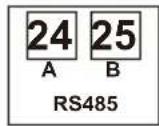
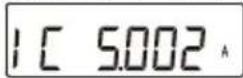
Phase C current =5.002A
Pic 7.13 CHINT meter
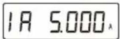
Phase A current =5.000A
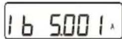
Phase B current =5.001A
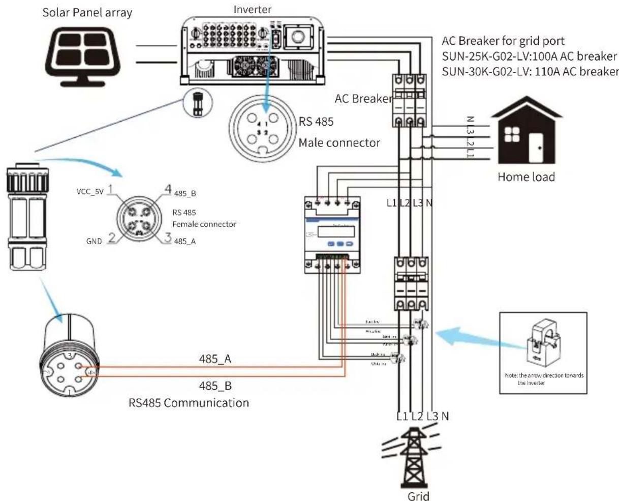
flowchart
graph TD
    A["Solar Panel array"] --> B["Inverter"]
    B --> C["RS 485 Male connector"]
    C --> D["AC Breaker for grid port SUN-25K-G02-LV:100A AC breaker"]
    C --> E["Home load"]
    F["VCC_5V"] --> G["RS 485 Female connector"]
    H["GND"] --> I["RS485 Communication"]
    J["Grid"] --> K["L1 L2 L3 N"]
    K --> L["AC Breaker"]
    L --> M["Home load"]
    N["Note: the arrow direction towards the inverter"] --> O["Grid"]
Pic 7.14 Connection diagram of CHNT meter
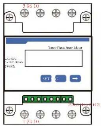
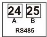
Phase C current =5.002A
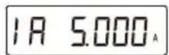
Phase A current =5.000A
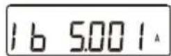
Phase B current =5.001A
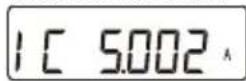
Pic 7.15 CHINT meter
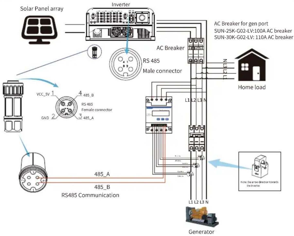
flowchart
graph TD
    A["Solar Panel array"] --> B["Inverter"]
    B --> C["AC Breaker for gen port"]
    C --> D["Home load"]
    D --> E["Generator"]
    E --> F["RS485 Communication"]
    F --> G["RS 485 Female connector"]
    G --> H["VCC_5V 1"]
    G --> I["GND 2"]
    H --> J["AC Breaker for gen port"]
    I --> K["AC Breaker for Gen port"]
    J --> L["SUN-25K-G02-LV:100A AC breaker"]
    K --> M["SUN-30K-G02-LV:110A AC breaker"]
    L --> N["AC Breaker for Gen port"]
    M --> O["AC Breaker for Gen port"]
    style A fill:#f9f,stroke:#333
    style B fill:#ccf,stroke:#333
    style C fill:#cfc,stroke:#333
    style D fill:#fcc,stroke:#333
    style E fill:#cff,stroke:#333
    style F fill:#ffc,stroke:#333
    style G fill:#cfc,stroke:#333
    style H fill:#fcc,stroke:#333
    style I fill:#ffc,stroke:#333
    style J fill:#cfc,stroke:#333
    style K fill:#cfc,stroke:#333
    style L fill:#fcc,stroke:#333
    style M fill:#cfc,stroke:#333
    style N fill:#fcc,stroke:#333
    style O fill:#cfc,stroke:#333
Pic 7.16 Connection diagram of CHNT meter

Safety Hint:
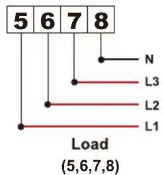
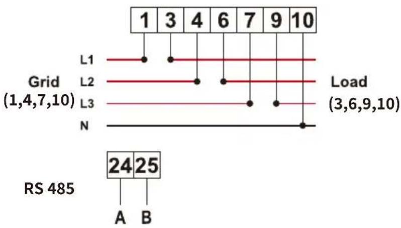
Ensuring grid input cables connect 1/4/7/10 port of energy meter, and inverter AC output cables connect 3/6/9/10 port of energy meter when connecting.
- Press Enter button on the LCD panel in the main interface into the menu options, select [parameter setting] to enter setup submenu, and then select [run param], at this time please input the default password 1234 through pressing the button [up down, enter], enter the operation parameter setting interface, shown as picture 7.17.
| MENU» Setup» Run Param | |||
| ActiveP | 31% | SelfCheck | 20S |
| QMode | QU | Island | OFF |
| ReactP | 0.0% | Meter | ON |
| PF | 1.000 | Limiter | OFF |
| Fun_ISO | ON | Feed_In | 0% |
| Fun_RCD | ON | MPPT Num | 4 |
| OK Cancel | |||
Pic 7.17 Zero-export function via meter setting interface
- Operate the button [up down], move setting cursor to energy meter and press the button [enter]. At this time you can turn on the energy meter by choosing [up down] button, please press [enter] button to confirm when setting done.
- Move the cursor to [OK], press [enter] to save the settings and exit the running parameters page, otherwise the settings are invalid.
- If set up successfully, you can return to the menu interface, and display the LCD to [home page] by press the [up down] button. If it displays [meter power XXW], the zero-export function setting is completed. Shown as picture 7.18.
| PARAMETR | Meter | |
| SN:1 | ||
| Meter Power: | 428W | |
| Load Power: | 1.043kW | |
| Day | Total | |
| ImpEp : 9.51kWh | 2.24MWh | |
| ExpEp : 0.00kWh | 574.75KWh | |
| LoadEp : 13.71kWh | 1.67MWh | |
Pic 7.18 Zero-export function via energy meter turn on
- Meter power 428W shows positive means grid is supplying the load, and no power fed into grid. if meter power shows negative, it means PV energy is being sold to grid or energy meter wiring connection has problem.
- After properly connection is done, wait for inverter starting. If the power of the PV array meets the current power consumption, the inverter will keep a certain output to counteract the power of the grid without backflow.
7.1 Multiple strings and parallel connection meters
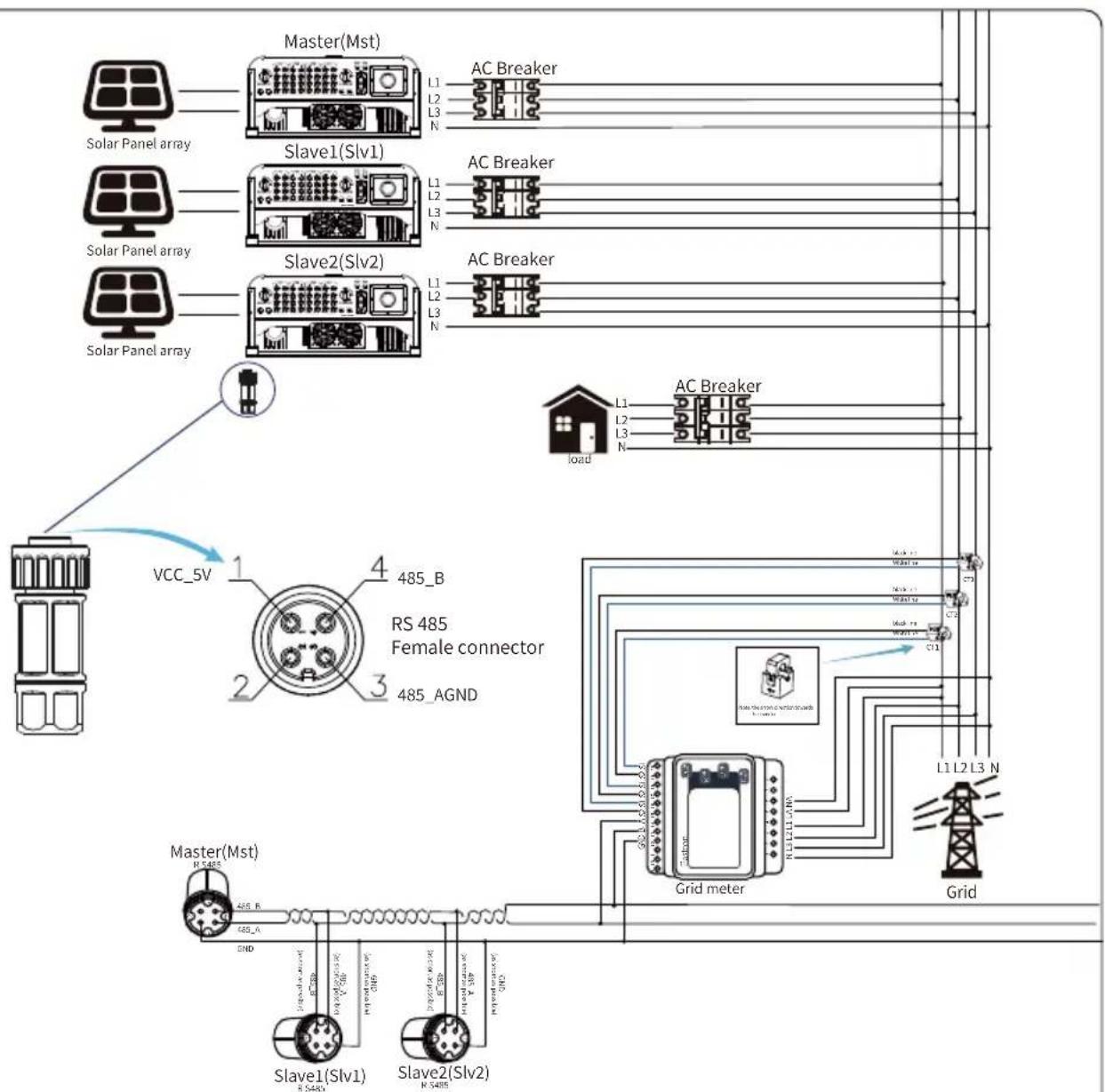
This application is that when the string inverters work in parallel, there is only one power grid and one load, and only one meter can be connected to prevent reverse current, so only this many-to-one anti-reverse current connection can be connected.
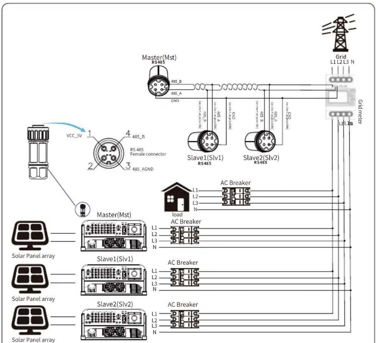
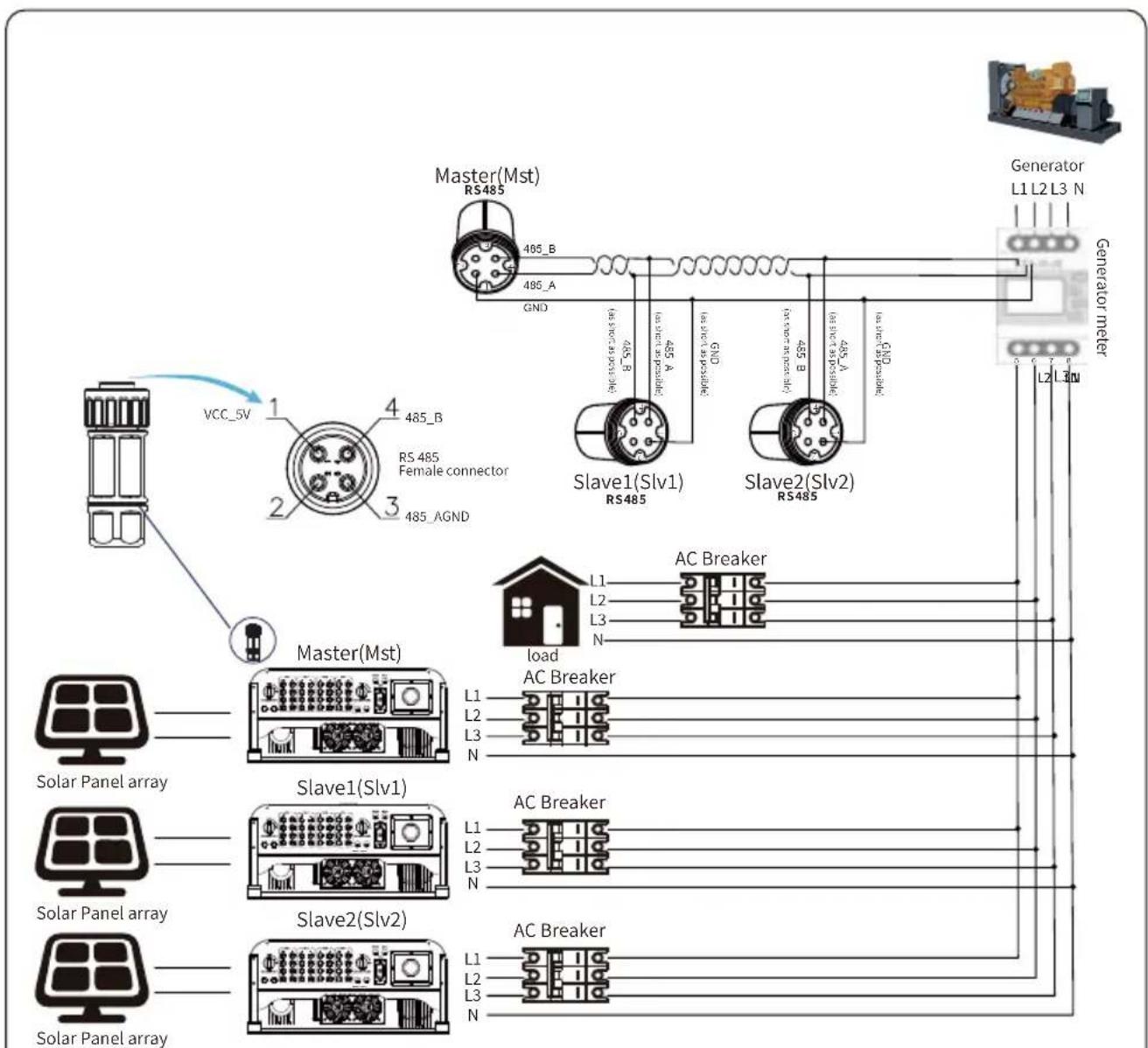
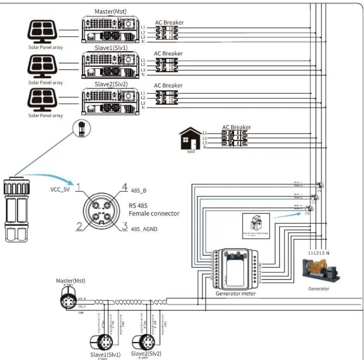
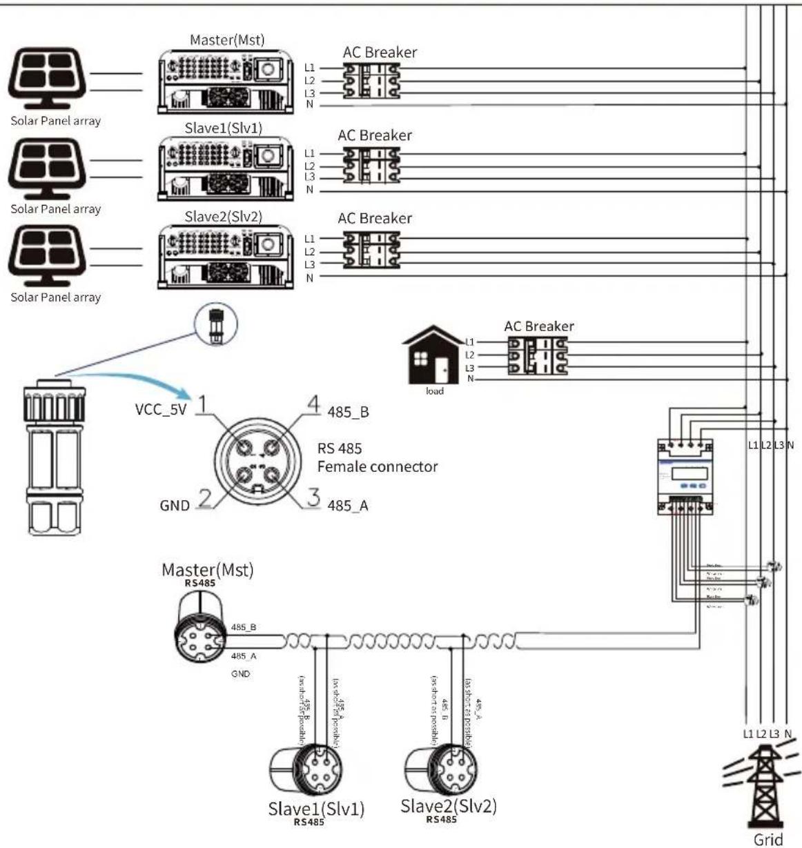
If there're several inverters parallelling operation in a plant, also it can use 1pcs meter to realize zero export function. For example, if there're 3pcs inverters parallelling operation in the system with 1pcs meter. We need to setup 1pcs inverteras the master and others setup as slaves. And, all of them need to connect to the meter via RS485. Below is the system diagram and configuration of the system.
| MENU Setting | |||
| Exp_Mode AVG | Generator | ON | |
| CT_Ratio | 1 | G.CT | 1 |
| MFR | AUTO | G.MFR | AUTO |
| FeedIn | 0.0KW | G.Pout | 0% |
| Shunt | OFF | G.Cap | 200.0 KW |
| ShuntQTY | 3 | ||
| Back | |||
Pic 7.19 Meter function
| Name Description | Range | |
| Exp_Mode | AVG: Average power of three phase is zero exported.MIN: Phase with minimum load power is zero exported, while the other two phase may be in purchase mode. | AVG/MIN |
| CT_Ratio | CT ratio of power grid side meter when extern CT is applied. | 1-1000 |
| MFR | Manufacturer of the grid side meter. Modbus Address of it should be set as 01. | AUTO/CHNT/EASTRON |
| Feedin | Percentage of the Feed in power exported to the grid. | 0-110% |
| Shunt | Parallel mode. Set one inverter as Master, others are Slave. ONLY need to set the master, Slave will follow the settings in the master. | OFF/Master/Slave |
| ShuntQTY | Number of inverters in parallel | 1-16 |
| Generator | DG side meter function Enable/Disable | ON/OFF |
| G.CT | CT ratio of power DG side meter when extern CT is applied. | 1-1000 |
| G.MFR | Manufacturer of the DG side meter. Modbus Address of it should be set as 02. | AUTO/CHNT/EASTRON |
| G.Pout | Output power percentage of the DG. | 0-110% |
| G.Cap | Capacity of the DG. | 1-999kW |
Note: Select Meter option in Run Param and long press ENTER button to enter this Meter Setting page.
Eastron SDM630-Modbus V2
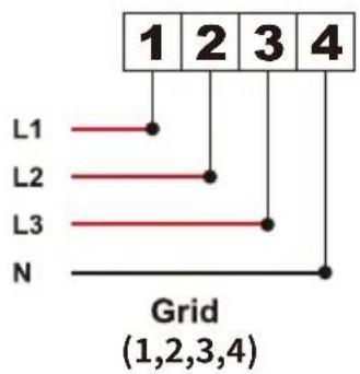
flowchart
graph TD
    A["1"] --> B["L1"]
    C["2"] --> D["L2"]
    E["3"] --> F["L3"]
    G["4"] --> H["N"]
    style A fill:#f9f,stroke:#333
    style C fill:#f9f,stroke:#333
    style E fill:#f9f,stroke:#333
    style G fill:#f9f,stroke:#333
    style B fill:#ccf,stroke:#333
    style D fill:#ccf,stroke:#333
    style F fill:#ccf,stroke:#333
    style H fill:#ccf,stroke:#333
RS 485
Pic 7.20 Eastron meter
flowchart
graph TD
    A["Power Supply"] --> B["Master(Mst)"]
    B --> C["Slave1(Slv1)"]
    B --> D["Slave2(Slv2)"]
    B --> E["Grid Meter"]
    C --> F["Load AC Breaker"]
    D --> G["AC Breaker"]
    E --> H["AC Breaker"]
    I["VCC_5V"] --> B
    J["RS 485 Female connector"] --> B
    K["RS485"] --> L["465_B"]
    K --> M["485_A"]
    N["485_AGND"] --> B
    O["485_A"] --> P["465_B (less shot as possible)"]
    Q["485_A"] --> R["465_B (less shot as possible)"]
    S["485_A"] --> T["465_B (less shot as possible)"]
    U["485_A"] --> V["465_B (less shot as possible)"]
    W["L1"] --> X["AC Breaker"]
    Y["L2"] --> Z["AC Breaker"]
    AA["L3"] --> AB["AC Breaker"]
    AC["L1"] --> AD["AC Breaker"]
    AE["L2"] --> AF["AC Breaker"]
    AG["L3"] --> AH["AC Breaker"]
    AI["L1"] --> AJ["AC Breaker"]
    AK["L2"] --> AL["AC Breaker"]
    AM["L3"] --> AN["AC Breaker"]
Pic 7.21 Eastron Connection diagram(The pass-through table)
Eastron SDM630-Modbus V2

flowchart
graph TD
    A["1"] --> B["L1"]
    C["2"] --> D["L2"]
    E["3"] --> F["L3"]
    G["4"] --> H["N"]
    style A fill:#f9f,stroke:#333
    style C fill:#f9f,stroke:#333
    style E fill:#f9f,stroke:#333
    style G fill:#f9f,stroke:#333
    style B fill:#ccf,stroke:#333
    style D fill:#ccf,stroke:#333
    style F fill:#ccf,stroke:#333
    style H fill:#ccf,stroke:#333
RS 485
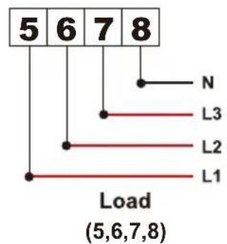
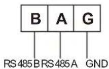
Pic 7.22 Eastron meter
flowchart
graph TD
    A["Solar Panel array"] --> B["Master(Mst)"]
    B --> C["Slave1(Slv1)"]
    B --> D["Slave2(Slv2)"]
    C --> E["Load"]
    D --> F["AC Breaker"]
    E --> G["Generator meter"]
    F --> G
    H["VCC_5V"] --> I["Master(Mst)"]
    I --> J["Slave1(Slv1)"]
    I --> K["Slave2(Slv2)"]
    J --> L["Load"]
    K --> M["AC Breaker"]
    L --> N["Generator meter"]
    M --> N
    style A fill:#f9f,stroke:#333
    style B fill:#ccf,stroke:#333
    style C fill:#cfc,stroke:#333
    style D fill:#fcc,stroke:#333
    style E fill:#ffc,stroke:#333
    style F fill:#cfc,stroke:#333
    style G fill:#fcc,stroke:#333
    style H fill:#f9f,stroke:#333
    style I fill:#ccf,stroke:#333
    style J fill:#cfc,stroke:#333
    style K fill:#fcc,stroke:#333
    style L fill:#ffc,stroke:#333
    style M fill:#cfc,stroke:#333
    style N fill:#fcc,stroke:#333
Pic 7.23 Eastron Connection diagram(The pass-through table)
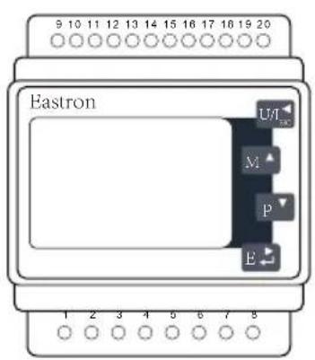
Eastron SDM630MCT
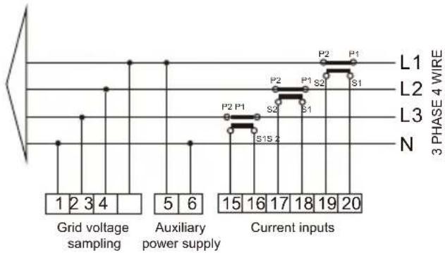
flowchart
graph TD
    A["Grid voltage sampling"] --> B["Current inputs"]
    C["Auxiliary power supply"] --> D["Current inputs"]
    style A fill:#f9f,stroke:#333
    style B fill:#ccf,stroke:#333
    style C fill:#cfc,stroke:#333
    style D fill:#fcc,stroke:#333
    subgraph Grid voltage sampling
        A1["1"] --> A2["2"] --> A3["3"] --> A4["4"] --> A5["5"] --> A6["6"]
    end
    subgraph Auxiliary power supply
        B1["15"] --> B2["16"] --> B3["17"] --> B4["18"] --> B5["19"] --> B6["20"]
    end
    subgraph Current inputs
        C1["P2 P1"] --> C2["S1S 2"] --> C3["P2 S2"] --> C4["S1"] --> C5["P1 S1"]
    end
    L1["L1"] --> L2["L2"] --> L3["L3"] --> N["N"]
RS 485
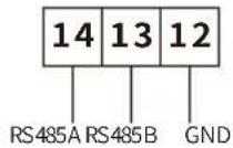
Pic 7.24 Eastron meter
flowchart
graph TD
    A["Solar Panel array"] --> B["Master(Mst)"]
    C["Solar Panel array"] --> D["Slave1(Slv1)"]
    E["Solar Panel array"] --> F["Slave2(Slv2)"]
    G["Solar Panel array"] --> H["Load"]
    I["VCC_5V"] --> J["RS 485 Female connector"]
    K["Master(Mst)"] --> L["Slave1(Slv1)"]
    K --> M["Slave2(Slv2)"]
    N["Grid meter"] --> O["AC Breaker"]
    P["Grid"] --> Q["L1 L2 L3 N"]
    R["485_B"] --> S["RS 485 Female connector"]
    T["AGND"] --> U["RS 485 AGND"]
    V["AC Breaker"] --> W["AC Breaker"]
    X["Grid meter"] --> Y["L1 L2 L3 N"]
    Z["AC Breaker"] --> AA["L1 L2 L3 N"]
Pic 7.25 Connection diagram(Three-phase electricity)
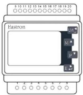
Eastron SDM630MCT
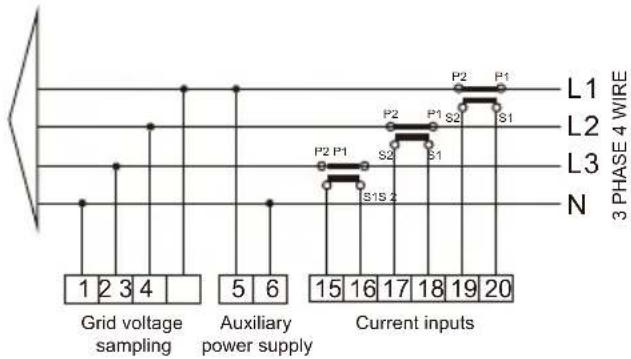
flowchart
graph TD
    A["Grid voltage sampling"] --> B["Current inputs"]
    C["Auxiliary power supply"] --> D["Current inputs"]
    style A fill:#f9f,stroke:#333
    style B fill:#ccf,stroke:#333
    style C fill:#cfc,stroke:#333
    style D fill:#fcc,stroke:#333
    subgraph Grid voltage sampling
        A1["1"] --> A2["2"] --> A3["3"] --> A4["4"] --> A5["5"] --> A6["6"]
    end
    subgraph Auxiliary power supply
        B1["15"] --> B2["16"] --> B3["17"] --> B4["18"] --> B5["19"] --> B6["20"]
    end
    subgraph Current inputs
        C1["P2 P1"] --> C2["S1S 2"] --> C3["P2 S2"] --> C4["S1"] --> C5["P1 S1"]
    end
    L1["L1"] --> L2["L2"] --> L3["L3"] --> N["N"]
    style L1 fill:#fff,stroke:#333
    style L2 fill:#fff,stroke:#333
    style L3 fill:#fff,stroke:#333
    style N fill:#fff,stroke:#333
RS 485
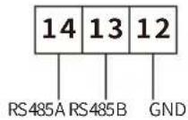
Pic 7.26 Eastron meter
flowchart
graph TD
    A["Solar Panel array"] --> B["Master(Mst)"]
    C["Solar Panel array"] --> D["Slave1(Slv1)"]
    E["Solar Panel array"] --> F["Slave2(Slv2)"]
    G["Solar Panel array"] --> H["AC Breaker"]
    I["VCC_5V"] --> J["RS 485 Female connector"]
    K["Generator meter"] --> L["AC Breaker"]
    M["Load"] --> N["AC Breaker"]
    O["485_B"] --> P["RS 485 AGND"]
    Q["485_A"] --> R["Slave1(Slv1)"]
    S["485_B"] --> T["Slave2(Slv2)"]
    U["L1 L2 L3 N"] --> V["AC Breaker"]
    W["L1 L2 L3 N"] --> X["AC Breaker"]
    Y["L1 L2 L3 N"] --> Z["AC Breaker"]
    AA["L1 L2 L3 N"] --> AB["AC Breaker"]
    AC["L1 L2 L3 N"] --> AD["AC Breaker"]
    AE["L1 L2 L3 N"] --> AF["AC Breaker"]
Pic 7.27 Connection diagram(Three-phase electricity)
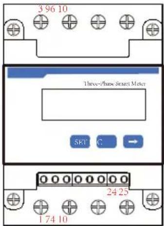
CHNT DTSU666
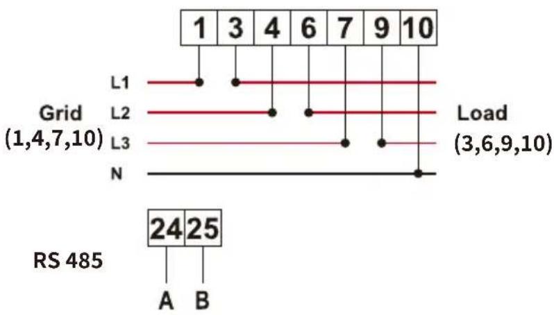
line
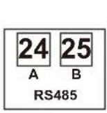
| Grid | Load | | :--- | :--- | | L1 | 3 | | L2 | 3 | | L3 | 3 | | N | 3 | RS 485 24 25 A BPic 7.28 CHNT meter
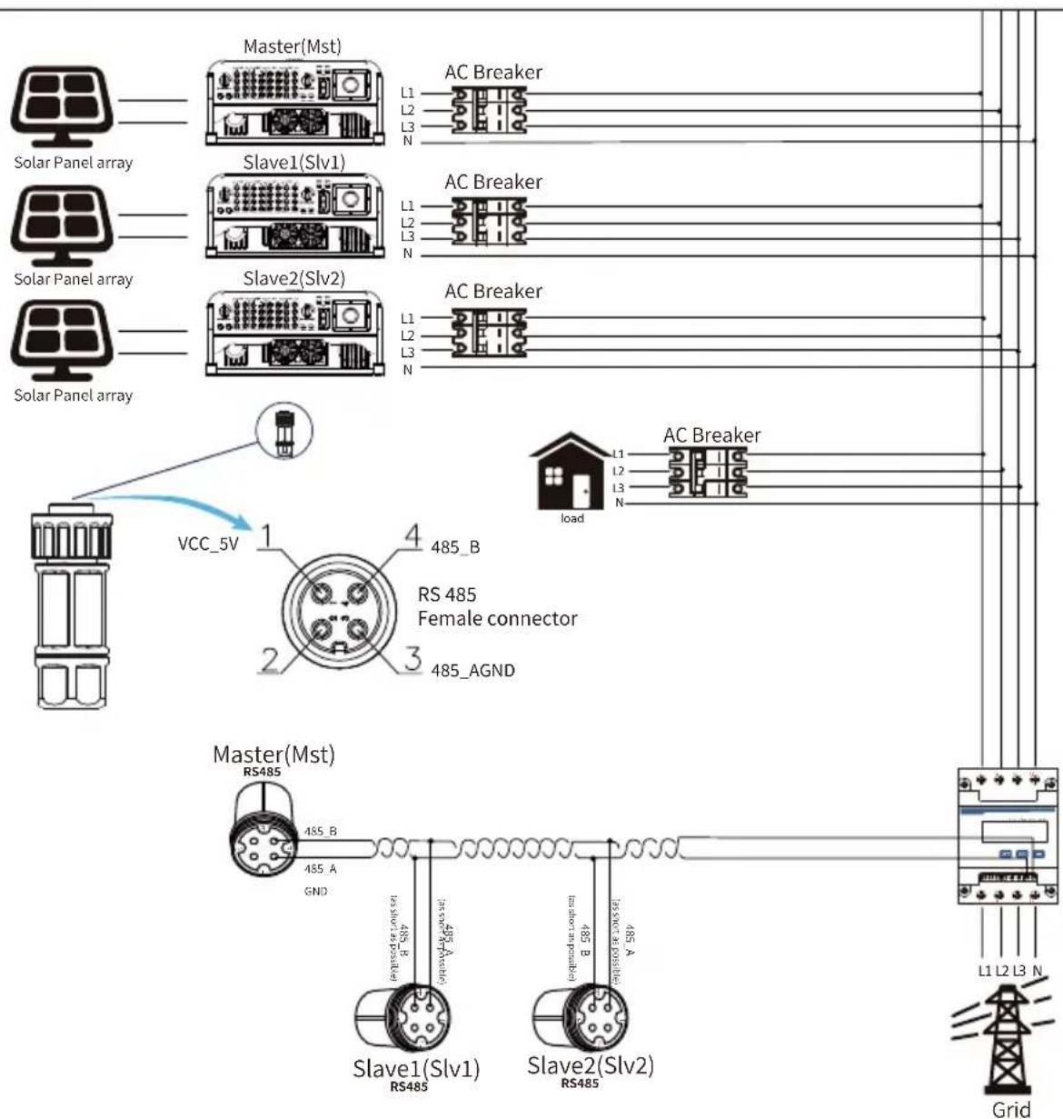
Pic 7.29 CHNT Connection diagram(The pass-through table)
CHNT DTSU666
line
| Grid | Load | | :--- | :--- | | L1 | 3 | | L2 | 3 | | L3 | 3 | | N | 3 | RS 485 24 25 A BPic 7.30 CHNT meter
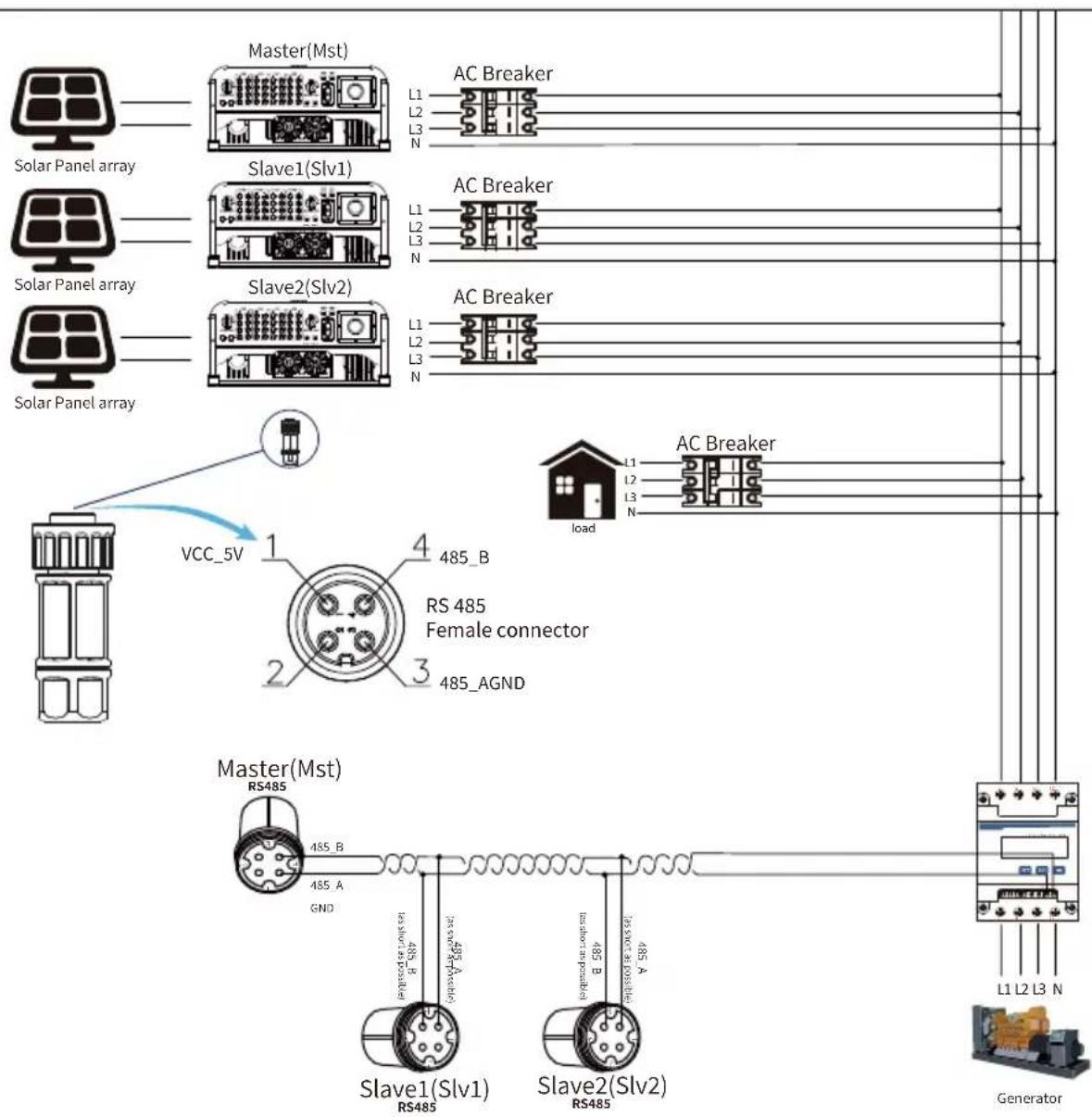
Pic 7.31 CHNT Connection diagram(The pass-through table)
line
| Phase | Phase A Current (A) | Phase B Current (A) | | :--- | :--- | :--- | | 1A | 5.000A | - | | 1B | - | - | | 24 | - | - | | 25 | - | - | | RS485 | - | - | | 16 | 5.001A | - | | 1C | 5.002A | - | Phase C current =5.002APic 7.32 CHINT meter
Pic 7.33 CHNT Connection diagram(The pass-through table)
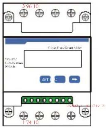
Phase C current =5.002A
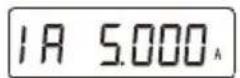
Phase A current =5.000A
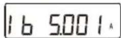
Phase B current =5.001A
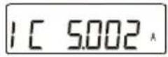
Pic 7.34 CHINT meter
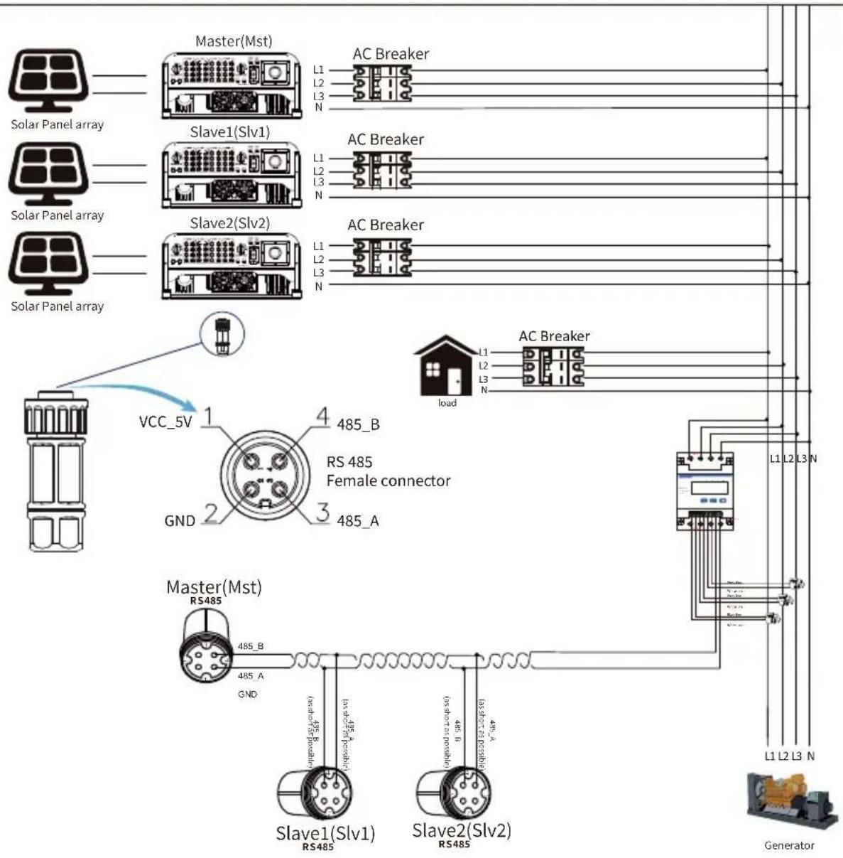
Pic 7.35 CHNT Connection diagram(The pass-through table)
7.2 How to browse the load power of your PV grid-tie plant on monitoring platform?
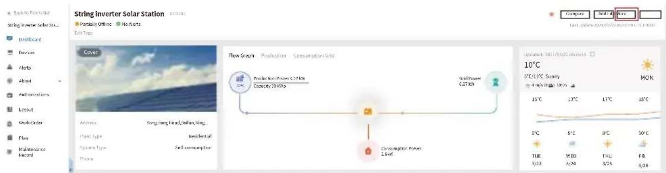
If you want to browse load power of the system and how much energy (KWH) does it export to grid(inverter output power is used to power the load firstly and then the surplus energy will feed into grid). You also need to connect the meter according to above diagram. After the connection completed successfully, the inverter will show the load power on the LCD. But please don’t setup “Meter ON”. Also, you will be able to browse the load power on the monitoring platform. The plant setting method as below description.
Firstly, go to the solarman platform(https://pro.solarmanpv.com, this link is for solarman distributor account; or https://home.solarmanpv.com, this link is for solarman end user account;) plant home page and click “edit”
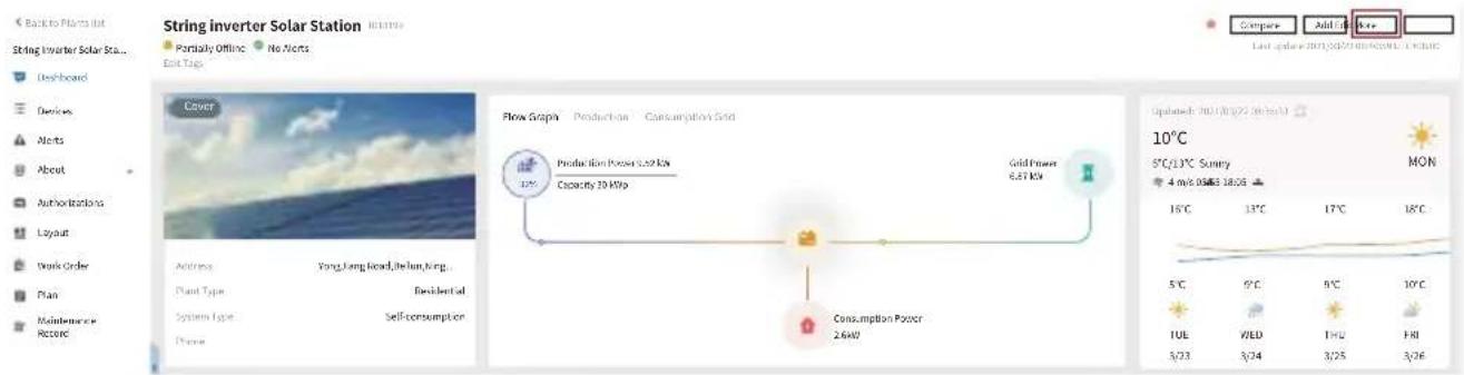
And then choose your system type as "Self-consumption"
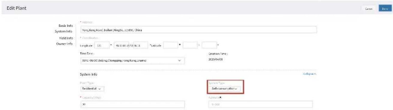
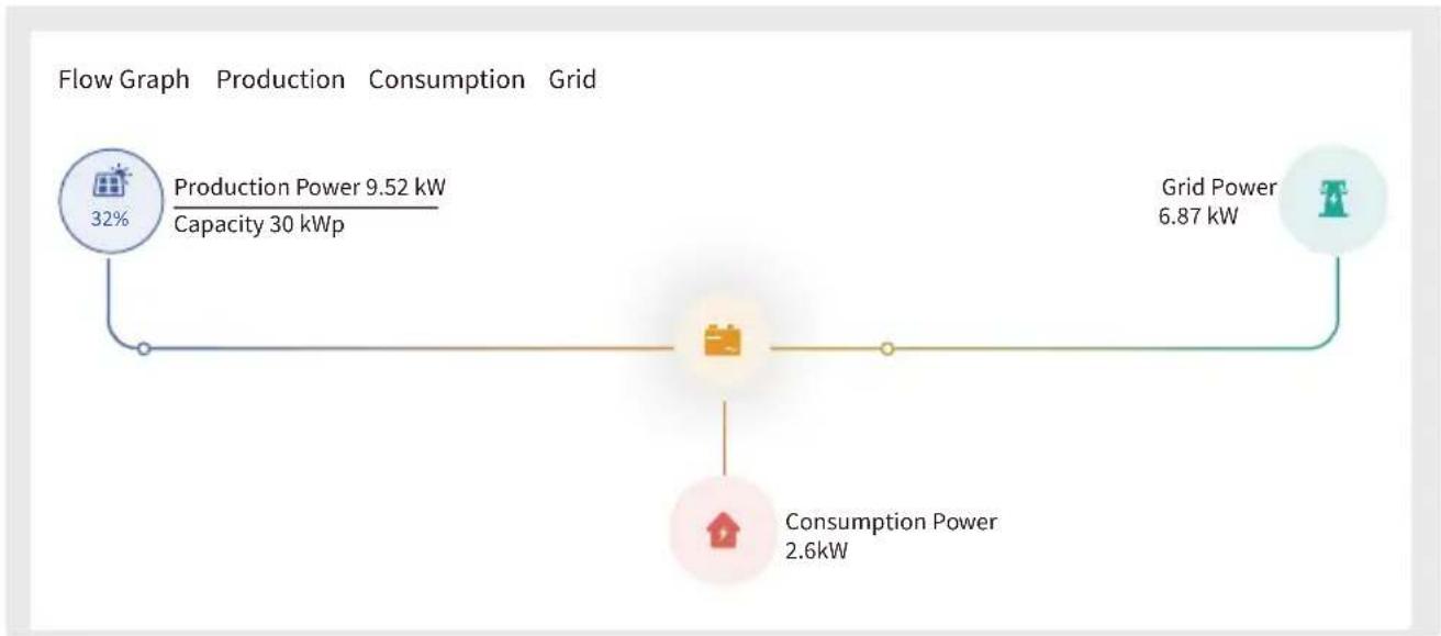
Secondly, go to plant page, if it shows the PV power, load power and grid power, which means the configuration is correct.
flowchart
graph LR
    A["Flow Graph"] --> B["Production Power 9.52 kW\nCapacity 30 kWp"]
    B --> C["Grid Power 6.87 kW"]
    C --> D["Consumption Power 2.6kW"]
8. General Operation
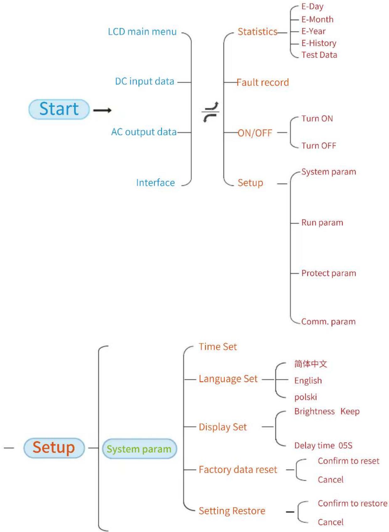
During normal operation, the LCD shows the current status of the inverter, including the current power, total generation, a bar chart of power operation and inverter ID, etc. Press the Up key and the Down key to see the current DC voltage, DC current, AC voltage, AC current, inverter radiator temperature, software version number and Wifi connection state of the inverter.
flowchart
graph TD
    A["Start"] --> B["LCD main menu"]
    A --> C["DC input data"]
    A --> D["AC output data"]
    A --> E["Interface"]
    B --> F["Statistics"]
    F --> G["E-Day"]
    F --> H["E-Month"]
    F --> I["E-Year"]
    F --> J["E-History"]
    F --> K["Test Data"]
    C --> L["Fault record"]
    L --> M["ON/OFF"]
    M --> N["Turn ON"]
    M --> O["Turn OFF"]
    C --> P["Setup"]
    P --> Q["System param"]
    P --> R["Run param"]
    P --> S["Protect param"]
    P --> T["Comm. param"]
    U["Setup"] --> V["System param"]
    V --> W["Time Set"]
    V --> X["Language Set"]
    X --> Y["简体中文"]
    X --> Z["English"]
    X --> AA["polski"]
    V --> AB["Display Set"]
    AB --> AC["Brightness Keep"]
    AB --> AD["Delay time 05S"]
    V --> AE["Factory data reset"]
    AE --> AF["Confirm to reset"]
    AE --> AG["Cancel"]
    V --> AH["Setting Restore"]
    AH --> AI["Confirm to restore"]
    AH --> AJ["Cancel"]
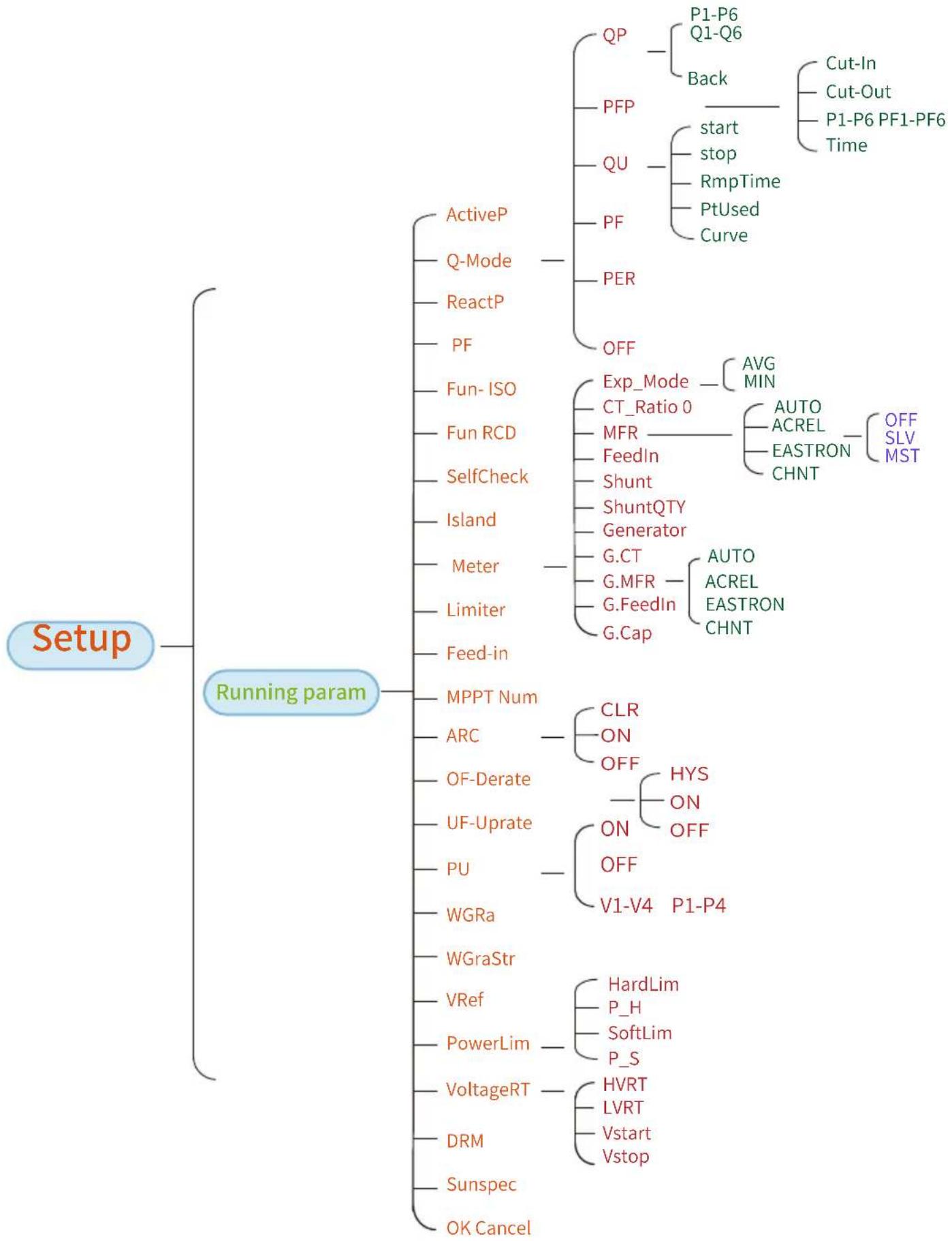
flowchart
graph TD
    A["Setup"] --> B["Running param"]
    B --> C["ActiveP"]
    B --> D["Q-Mode"]
    B --> E["ReactP"]
    B --> F["PF"]
    B --> G["Fun-ISO"]
    B --> H["Fun RCD"]
    B --> I["SelfCheck"]
    B --> J["Island"]
    B --> K["Meter"]
    B --> L["Limiter"]
    B --> M["Feed-in"]
    B --> N["MPPT Num"]
    B --> O["ARC"]
    B --> P["OF-Derate"]
    B --> Q["UF-Uprate"]
    B --> R["PU"]
    B --> S["WGRa"]
    B --> T["WGraStr"]
    B --> U["VRef"]
    B --> V["PowerLim"]
    B --> W["VoltageRT"]
    B --> X["DRM"]
    B --> Y["Sunspec"]
    B --> Z["OK Cancel"]

    C --> C1["QP"]
    C1 --> C1a["P1-P6\nQ1-Q6"]
    C1 --> C1b["Back"]
    C1b --> C1b1["Cut-In\nCut-Out\nP1-P6 PF1-PF6\nTime"]

    C --> C2["PFP"]
    C2 --> C2a["Start\nstop\nRmpTime\nPtUsed\nCurve"]

    C --> C3["QU"]
    C3 --> C3a["PER"]

    C --> C4["PF"]

    C4 --> C4a["OFF"]

    D --> D1["Exp_Mode"]
    D1 --> D1a["CT_Ratio 0"]
    D1 --> D1b["MFR"]
    D1 --> D1c["FeedIn"]
    D1 --> D1d["Shunt"]
    D1 --> D1e["ShuntQTY"]
    D1 --> D1f["Generator"]

    D --> D2["G.CT"]
    D2 --> D2a["G.MFR"]
    D2 --> D2b["G.FeedIn"]
    D2 --> D2c["G.Cap"]

    D3 --> D3a["AUG\nMIN"]
    D3 --> D3b["AUTO\nACREL\nEASTRON\nCHNT"]

    D4 --> D4a["AUTO\nACREL\nEASTRON\nCHNT"]

    E --> E1["CLR"]
    E1 --> E1a["ON"]
    E1 --> E1b["OFF"]

    E2["OFF"] --> E2a["HYS"]
    E2 --> E2b["ON"]
    E2 --> E2c["OFF"]

    F --> F1["ON"]
    F1 --> F1a["OFF"]

    F2["V1-V4"] --> F2a["P1-P4"]

    G --> G1["HardLim"]
    G1 --> G1a["P_H"]
    G1 --> G1b["SoftLim"]
    G1 --> G1c["P_S"]

    H --> H1["HVRT"]
    H1 --> H1a["LVRT"]
    H1 --> H1b["Vstart\nVstop"]
flowchart
graph TD
    A["Setup"] --> B["Protect Param"]
    A --> C["Comm. param"]
    B --> D["GridStandard"]
    B --> E["Advanced"]
    B --> F["Back"]
    D --> G["INMETRO"]
    D --> H["EN50549"]
    D --> I["EN50438"]
    D --> J["IEC61727"]
    D --> K["CUSTOM"]
    D --> L["VDE_4105"]
    D --> M["UTE_C15"]
    D --> N["RD1699"]
    D --> O["CEI_0_21"]
    D --> P["G98_G99"]
    D --> Q["AS4777(.2)"]
    D --> R["NB/T 32004"]
    D --> S["MEA"]
    D --> T["PEA"]
    T --> U["OV_3-OV_1 240.0V"]
    T --> V["Tov_3-Tov_1 1000ms"]
    T --> W["UV_1-UV_3 235.0V"]
    T --> X["Tuv_1-Tuv_3 1000ms"]
    T --> Y["OF_3-OF_1 52.00HZ"]
    T --> Z["Tof_3-Tof_1 1000ms"]
    T --> AA["UF_1-UF_3 48.00HZ"]
    T --> AB["Tuf_1-Tuf_3 1000ms"]
    T --> AC["Vrc_H"]
    T --> AD["Vrc_L"]
    T --> AE["Frc_H"]
    T --> AF["Frc_L"]
    T --> AG["VGrid 127/220V"]
    T --> AH["OV10Min"]
    T --> AI["Uov"]
    C --> AJ["Address:08"]
    C --> AK["Meter:Unkonw"]
    C --> AL["BaudRate:9600"]
8.1 The initial interface
From the initial interface, you can check power, daily generation, gross generation, invertert ID, model and time.
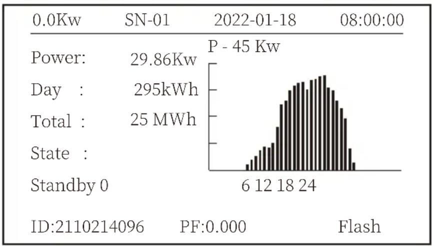
histogram
| Metric | Value | | :--- | :--- | | Power: | 29.86Kw | | Day : | 295kWh | | Total : | 25 MWh | | State : | | | Standby 0 | | | P - 45 Kw | | | 6 | 12 | | 18 | 24 | | Flash | | | ID:2110214096 PF:0.000Pic 8.1 The initial interface
Press UP or Down you can check inverter DC voltage, DC current, AC voltage, AC current, inverter temperature, software version information.
| RUN Input | |||
| PV1 | V : 349.9V | I : 10.3A | P : 3.6KW |
| PV2 | V : 313.0V | I : 8.3A | P : 2.6KW |
Pic 8.2 PV input and DC current information
You can check the PV information, the number of strings input, MPPT voltage and MPPT current.
| RUN Grid |
| Ua : 234.5V Ia : 0.0A |
| Grid Freq : 50.00Hz PF : 0.000 |
Pic 8.3 AC running state information
You can check the three phase voltage, current, and grid frequency.
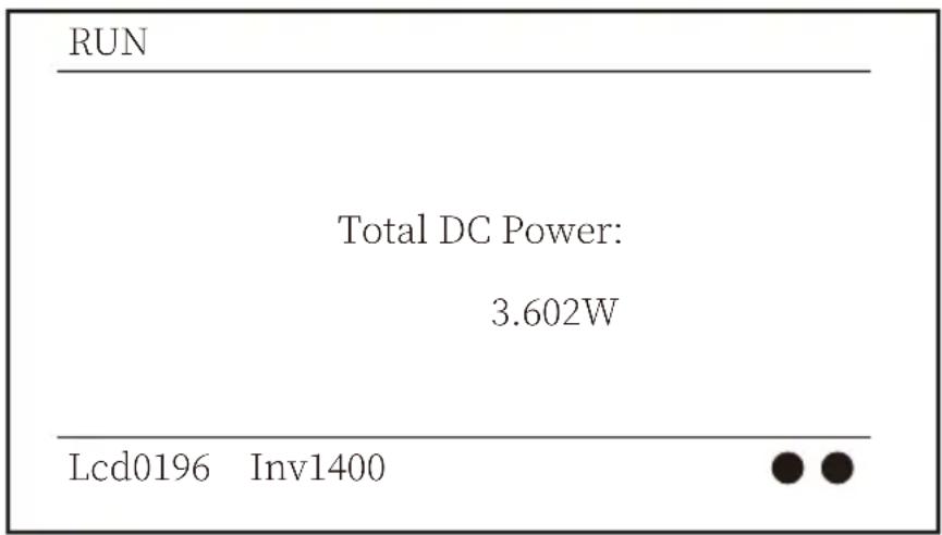
Pic 8.4 Inverter firmware version
You can check the inverter LCD software Ver0196 and Control Software Version Ver1400. There are two black spot in the bottom right corner. The first flash means inverter is communicating with LCD. The second flash means LCD is communicating with wifi plug.
| PARAMETR | Meter | |
| SN: 0 | ||
| Meter Power: | 0W | |
| Load Power: | 0W | |
| Day | Total | |
| ImpEp : 0.00kWh | 0.00kWh | |
| ExpEp : 0.00kWh | 0.00kWh | |
| LoadEp : 0.00kWh | 0.00kWh | |
Pic 8.5 Meter power and load power
8.1.1 Main Menu
There are four submenu in the Main Menu.
| MENU |
| Statistics « |
| Fault Record |
| ON/OFF |
| Setup |
Pic 8.6 Main Menu
8.2 Statistics information
There are five submenu in the statistics.
| MENU》Statistics | ||
| E-Day E-History | ||
| E-Month | Test Data | 《 |
| E-Year | ||
Pic 8.7 Statistics
Into each submenu through cursor.
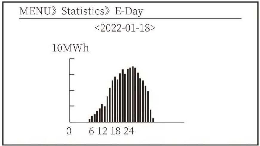
histogram
MENU》Statistics》E-Day | Time (min) | Energy Consumption (10MWh) | | :--- | :--- | | 0-3 | 0 | | 3-6 | 1 | | 6-9 | 3 | | 9-12 | 5 | | 12-15 | 7 | | 15-18 | 10 | | 18-21 | 14 | | 21-24 | 16 | | 24-27 | 15 | | >27 | 8 |Pic 8.8 E-Day
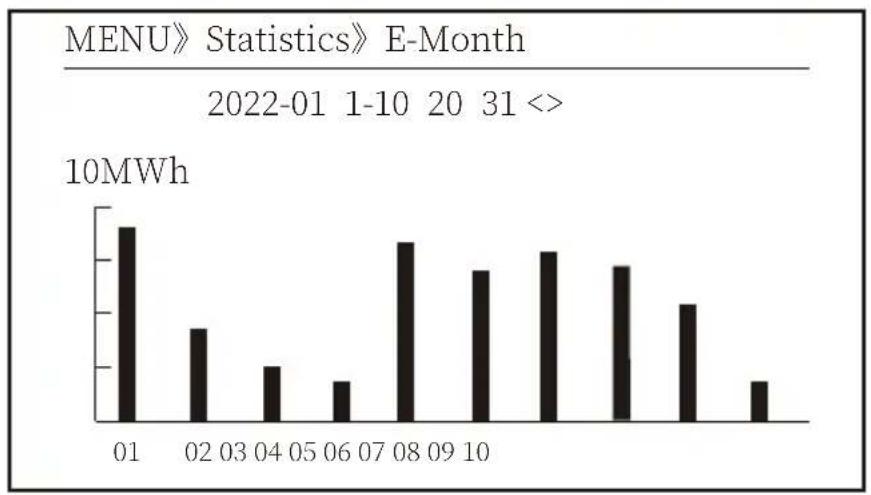
bar
MENU》 Statistics》 E-Month | Month | Value (10MWh) | |---|---| | 01 | 9.5 | | 02 | 3.8 | | 03 | 0.0 | | 04 | 2.5 | | 05 | 0.5 | | 06 | 1.8 | | 07 | 0.0 | | 08 | 7.2 | | 09 | 0.0 | | 10 | 5.5 | | | 6.8 | | | 6.2 | | | 5.8 | | | 4.2 | | | 1.5 |Pic 8.9 E-Month
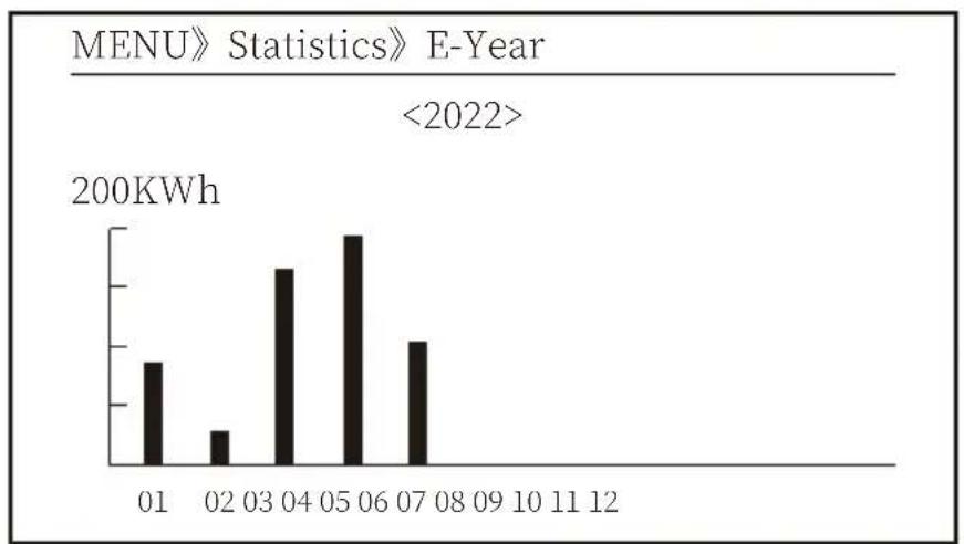
bar
MENU》 Statistics》 E-Year | Month | Energy Consumption (200KWh) | | :--- | :--- | | 01 | 80 | | 02 | 30 | | 03 | 150 | | 04 | 180 | | 05 | 200 | | 06 | 190 | | 07 | 120 | MENU》 Statistics》 E-Year <2022>Pic 8.10 E-Year
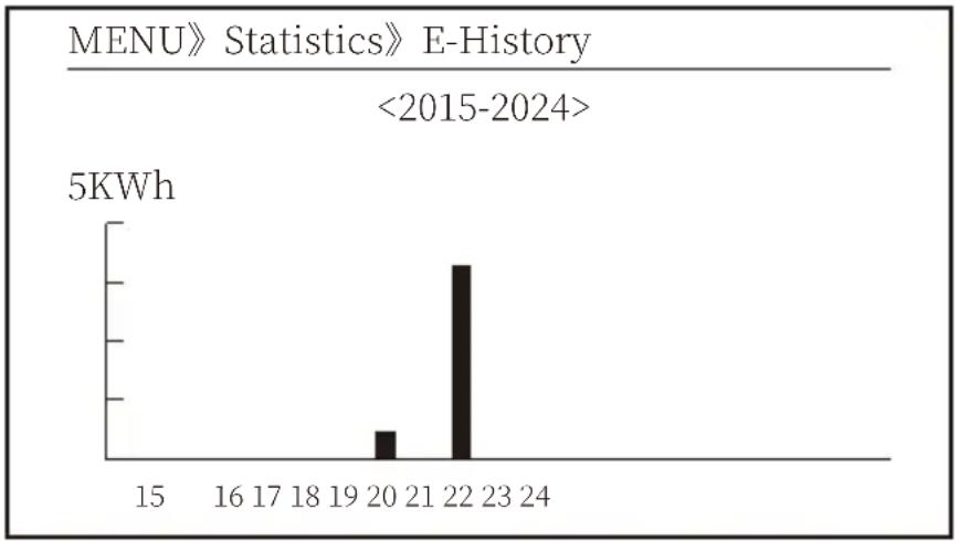
Pic 8.11 E-History
This information is for technician's reference.
Only can keep four fault record in the menu include time, customer can deal with it depends on the error code.
| MENU》Fault Record | |
| Fault : F352022-01-05 08:38 | |
| History : 1 | F352022-01-05 08:37 |
| 2 | F352022-01-04 18:47 |
| 3 | F352022-01-04 17:54 |
| 4 | F352022-01-04 17:53 |
Pic 8.13 Fault Record
8.4 ON/OFF setting
MENU》ON/OFF
Turn ON
Turn OFF 《
Pic 8.14 ON/OFF setting
Into each submenu through cursor.
MENU》ON/OFF》Turn ON
OK 《 Turn ON Cancel
Pic 8.15 ON set
MENU》ON/OFF》Turn OFF
OK 《 Turn OFF Cancel
Pic 8.16 OFF set
8.5 Parameter setting
Setting includes system param, run param, protect param, comm.. param. All of these information for maintenance reference.
MENU》 Setup
System Param 《
Run Param
ParamProtect
ParamComm.
Pic 8.17 Setting
8.5.1 System Param
MENU》 Setup \$ystem Param
Time Set
Language Set
Display Set
Factory data reset
Setting Restore
Pic 8.17.1 System Param Setting
8.5.1.1 Time Set
Time Set
2022-01-18 09:36:30
OK Cancel
Pic 8.18 System Param
8.5.1.2 Language Set
Lauguage Set
简体中文
English 《
Polski
Pic 8.19 Lauguage set
8.5.1.3 Display Set
Display Set
Brightness Keep 《
Delay time 05S
OK Cancel
Pic 8.20 Display set
8.5.1.4 Factory data reset
Factory data reset
Confirm to reset 《
Cancel
Pic 8.21 Factory data reset set
Password required-- only for access-authorized engineer. Un-authorized access may avoid the warranty. The initial password is 1234.
8.5.2 Run Param
PassWord

Pic 8.23 Password
| Name Description | Range | |
| ActiveP | Adjust the output active power in % 0-110% | |
| QMode | Multiple reactive power control modes | OFF/Q(P)/PF(P)/Q(U)/PF/PER |
| -100%-+100%Re | ||
| PF | Power Fator | -1-0.8~+0.8-1 |
| Fun_ISO | Insulation resistance detection | ON/OFF |
| Fun_RCD | Residual current detection | ON/OFF |
| Self-check | Inverter's self-check time.The default value 60s | 0-1000s |
| Island | Anti-islanding protection | ON/OFF |
| Meter | Energy meter.If inverter will connect meter,then set here to ON | ON/OFF |
| Feed_IN % | It is used to deploy how much power can be feed in to grid when the inverter works under zero export mode.(For example,Feed_in=50% of the 30KW modeland loadpower is 14KW. which means Max 15KW power can befeed into grid after inverter providing 14Kw to the load firstly. | 0-100% |

Warning:
Engineer Only.
We will set the param depends on the safety requirements, so customers don't need to reset it.
The password is same as 8.23 Running param
| Name Description Range | ||
| ARC | Arc-fault detection function | ON/OFF/Clear |
| OFDerate | Active power response to over frequency | 0-100% Pmax/Hz |
| UFUprate | Active power response to under frequency | 0-100% Pmax/Hz |
| PU | power response to grid voltage deviation | ON/OFF |
| WGra | Active power ramp rate (% Pnom/Sec) | 0.1%-50% |
| WGraStr | Active power ramp rate at first start (% Pnom/Sec) | 0.1%~50% |
| Vref | Grid reference voltage for functions including Q(U),PF(P),P(U)etc. | 80-260V |
| PowerLimit | Hard/soft export limit control | ON/OFF |
| voltage ride through function | ON/OFFVoltageRT | |
| Demand Response Modes | ON/OFFDRM | |
| Sunspec | Sunspec Function | ON/OFF |
Pic 8.24 Run Param
| MENU》 Setup》 Run Param | |||
| ARC | OFF Vref | 0.0V | |
| OFDerate | OFF | PowerLimit | |
| UFUprate | OFF | VoltageRT | |
| PU | ON | DRM | OFF |
| Sunspec | OFFWGra | ||
| Sunspec | OFF | ||
| OK Cancel | |||
0.0%
| Voltage Ride Through | ||
| HVRT | OFF LVRT | OFF |
| Vstart | 0.0% Vstart | 0.0% |
| Vstop | 0.0% Vstop | 0.0% |
| ZVRT | OFF | |
| OK Cancel | ||
Pic 8.25 Voltage Ride Through
8.5.2.1 Over-frequency Response
This series inverter provides “over-frequency response” function.
Long pressing the “OFD Derate” to enter the “over-frequency response” setting menu.
| MENU》 Setup》 Run Param | |||
| ARC | OFF | Vref | 220.0V |
| OFDerate | ON | PowerLimit | |
| UFUprate | OFF | VoltageRT | |
| PU | OFF | DRM | OFF |
| WGra | 20.0% | Sunspec | OFF |
| Sunspec | OFF | ||
| OK Cancel | |||
Definition of Over-frequency Response Parameters
| Parameter | Range | Description |
| StartPoint | 45HZ-65HZ | The Start frequency value for over-frequency response. |
| StopPoint | 45HZ-65HZ | The Stop frequency value for over-frequency response. |
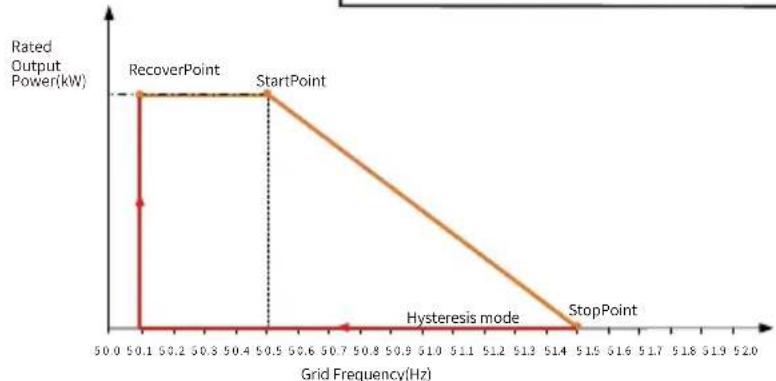
| RecoverPoint | 45HZ-65HZ | In hysteresis mode, power is restored only when it is below this frequency |
| RecoverGradient | 0.3%-300% P/min | Ramp rate of power recovery |
| RecoverDelay | 0-1000s | Time Delay of power recovery in hysteresis mode |
| ResponseDelay 0-2000S | Response delay time after entering active power frequency mode | |
For example, StartPoint: 50.5Hz, StopPoint: 51.5Hz, RecoverPoint: 50.1Hz, when the grid frequency increases beyond StartPoint: 50.5Hz, the inverter will linearly reduce the power output with a gradient of 100% Pmax/Hz until it reaches StopPoint: 51.5Hz.
| OverFrequencyDerate | |
| StartPoint | 50.50Hz |
| StopPoint | 51.50Hz |
| RecoverPoint | 50.1Hz |
| RecoverGradient | 1.00% |
| RecoverDelay | 0S |
| ResponseDelay | 0.0S |
| Back | |
line
| Grid Frequency(Hz) | Rated Output Power(kW) | | ------------------ | ---------------------- | | 50.0 | High | | 50.1 | High | | 50.5 | High | | 51.4 | Low |Frq-Watt Mode for Overfrequency Conditions
When the frequency exceeds StopPoint: 51.5Hz, the inverter output should stop (ie 0 W).
When the frequency is lower than StopPoint: 51.5 Hz, the inverter will linearly increase the power output with a gradient of 100% Pmax/Hz until it reaches StopPoint: 50.5 Hz.
In the hysteresis mode, when the frequency is lower than StopPoint: 51.5 Hz, the inverter will not increase the power output until it is lower than RecoverPoint: 50.1 Hz.
The inverter provides a reactive power regulation function.
Tap Reactive Power Regulation Mode to select proper regulation mode and set the corresponding parameters.
- "OFF" Mode
The reactive power regulation function is disabled. The PF is fixed at +1.000
- ReactiveP
Adjust reactive power output in %.
- "PF" Mode
The power factor (PF) is fixed and the reactive power is regulated by the parameter PF. The PF ranges from 0.8 leading to 0.8 lagging.
- Leading: the inverter is sourcing reactive power to the grid.
- Lagging: the inverter is injecting reactive power into the grid.
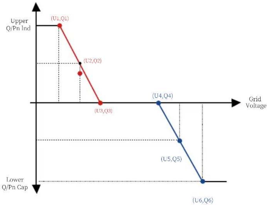
• "Q(U)" Mode
The reactive power output of the inverter varies in response to the grid voltage.
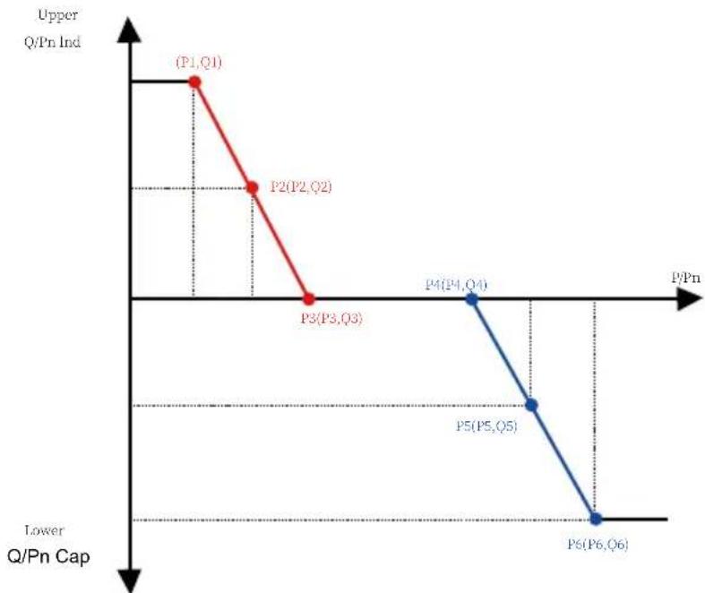
• "Q(P)" Mode
The reactive power output by the inverter is controlled by the active power of the inverter.
“Q(U)” Mode
QU Setting
| Start | 30.0% | Stop | 20.0% |
| RmpTime | 2s PtUsed | 4 | |
| Curve | Uref | OFF | |
| UrfTime |
Back
QU Setting
| V1 | 80.0% | Q1 | -25.0% |
| V2 | 90.0% | Q2 | 0.0% |
| V3 | 110.0% | Q3 | 0.0% |
| V4 | 120.0% | Q4 | 25.0% |
| V5 | 120.0% | Q5 | 25.0% |
| V6 | 120.0% | Q6 | 25.0% |
Back
line
| Grid Voltage | Upper Q/Pn Ind | Lower Q/Pn Cap | | :--- | :--- | :--- | | U1,Q1 | | | | U2,Q2 | | | | U3,Q3 | | | | U4,Q4 | | | | U5,Q5 | | | | U6,Q6 | | |Pic 8.26 Reactive Power Regulation Curve in Q(U) Curve
| Parameter Range Description | ||
| Start 0%-130% Rate out power | The QU mode starts when the active power is greater than this value | |
| Stop | 0%-130% Rate out power | The QU mode stops when the active power is less than this value |
| RMpTime | 0-1000s | Increase or decrease the time required for the reactive power to reach the specified value of the curve. |
| PtUsed | 2-6 | Point number used in QU Curve |
| Curve | QU Curve | |
| Q1 | -60% -60% Q/Pn | Value of Q/Pn at point (U1,Q1) on the Q(U) mode curve |
| V1 | 0-110% VRated | Grid voltage limit at point (U1,Q1) on the Q(U) mode curve |
| Q2 | -60% -60% Q/Pn | Value of Q/Pn at point (U2,Q2) on the Q(U) mode curve |
| V2 | 0-110% VRated | Grid voltage limit at point (U2,Q2) on the Q(U) mode curve |
| Q3 | -60% -60% Q/Pn | Value of Q/Pn at point (U3,Q3) on the Q(U) mode curve |
| V3 | 0-110% VRated | Grid voltage limit at point (U3,Q3) on the Q(U) mode curve |
| Q4 | -60% -60% Q/Pn | Value of Q/Pn at point (U4,Q4) on the Q(U) mode curve |
| V4 | 0-110% VRated | Grid voltage limit at point (U4,Q4) on the Q(U) mode curve |
| Q5 | -60% -60% Q/Pn | Value of Q/Pn at point (U5,Q5) on the Q(U) mode curve |
| V5 | 0-110% VRated | Grid voltage limit at point (U5,Q5) on the Q(U) mode curve |
| Q6 | -60% -60% Q/Pn | Value of Q/Pn at point (U6,Q6) on the Q(U) mode curve |
| V6 | 0-110% VRated | Grid voltage limit at point (U6,Q6) on the Q(U) mode curve |
"Q(U)" Mode Parameters Explanation
“Q(P)” Mode
The reactive power output by the inverter is controlled by the active power of the inverter.
line
| Point | Upper Q/Pn Ind | Lower Q/Pn Cap | |---|---|---| | P1,Q1 | High | Low | | P2(P2,Q2) | Medium | Low | | P3(P3,Q3) | Low | Low | | P4(P4,Q4) | Low | Low | | P5(P5,Q5) | Low | Medium | | P6(P6,Q6) | Low | Low |Pic 8.27 Reactive Power Regulation Curve in Q(P) Mode
| MENU》 Setup》 Run Param | |||
| ActiveP | 31% | SelfCheck | 20S |
| QMode | QP | Island | OFF |
| ReactP | 0.0% | Meter | ON |
| PF | 1.000 | Limiter | OFF |
| Fun_ISO | ON | Feed_In | 0% |
| Fun_RCD | ON | MPPT Num | 4 |
| OK Cancel | |||
| QP Setting | |||
| P1 | 80.0% | Q1 | -25.0% |
| P2 | 90.0% | Q2 | 0.0% |
| P3 | 110.0% | Q3 | 0.0% |
| P4 | 120.0% | Q4 | 25.0% |
| P5 | 120.0% | Q5 | 25.0% |
| P6 | 120.0% | Q6 | 25.0% |
| Back | |||
| Parameter Range Description | ||
| P1 | 0%-100% Pn | Value of Q/Pn at point (P1,Q1) on the Q(P) mode curve |
| Q1 | -60% -60% Q/Pn | Reactive power value at point (P1,Q1) on the Q(P) mode curve |
| P2 | 0%-100% Pn | Value of Q/Pn at point (P2,Q2) on the Q(P) mode curve |
| Q2 | -60% -60% Q/Pn | Reactive power value at point (P2,Q2) on the Q(P) mode curve |
| P3 | 0%-100% Pn | Value of Q/Pn at point (P3,Q3) on the Q(P) mode curve |
| Q3 | -60% -60% Q/Pn | Reactive power value at point (P3,Q3) on the Q(P) mode curve |
| P4 | 0%-100% Pn | Value of Q/Pn at point (P4,Q4) on the Q(P) mode curve |
| Q4 | -60% -60% Q/Pn | Reactive power value at point (P4,Q4) on the Q(P) mode curve |
| P5 | 0%-100% Pn | Value of Q/Pn at point (P5,Q5) on the Q(P) mode curve |
| Q5 | -60% -60% Q/Pn | Reactive power value at point (P5,Q5) on the Q(P) mode curve |
| P6 | 0%-100% Pn | Value of Q/Pn at point (P6,Q6) on the Q(P) mode curve |
| Q6 | -60% -60% Q/Pn | Reactive power value at point (P6,Q6) on the Q(P) mode curve |
"Q(P)" Mode Parameters Explanation
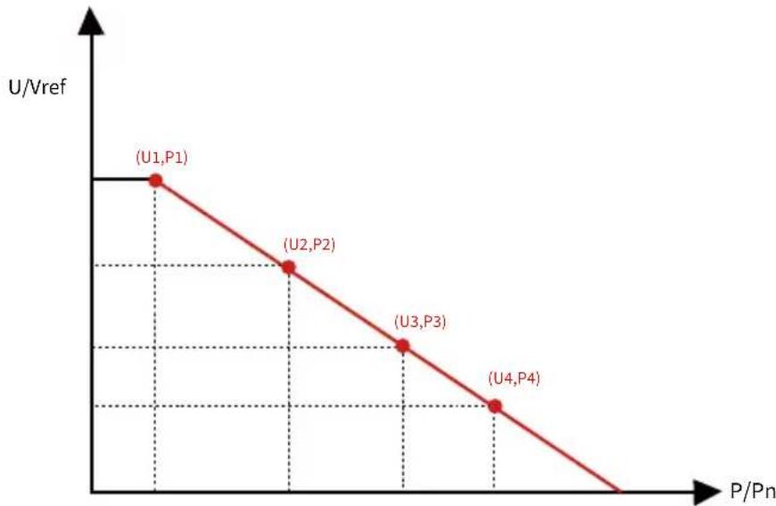
"PU" Mode
The active power output of the inverter varies in response to the grid voltage
| MENU》 Setup》 Run Param | |||
| ARC | OFF Vref | 0.0V | |
| OFDerate | OFF | PowerLimit | |
| UFUprate | OFF | VoltageRT | |
| PU | ON | DRM | OFF |
| Sunspec | OFFWGra | ||
| Sunspec | OFF | ||
| OK Cancel | |||
| PU Setting | |||
| U1 | 0.0% | P1 | 0.0% |
| U2 | 0.0% | P2 | 0.0% |
| U3 | 0.0% | P3 | 0.0% |
| U4 | 0.0% | P4 | 0.0% |
| RmpTime OS | |||
| Back | |||
line
| Point | P/Pn | U/Vref | |---|---|---| | (U1,P1) | 0.5 | 1.0 | | (U2,P2) | 1.0 | 0.7 | | (U3,P3) | 1.5 | 0.5 | | (U4,P4) | 2.0 | 0.3 |Pic 8.28 Active Power Regulation Curve in PU Curve
| Parameter Range Description | ||
| P1 | 0%-110% Pn | Value of P/Pn at point (P1,U1) on the PU mode curve |
| U1 | 0%-150% Vref | Grid voltage limit at point (P1,U1) on the PU mode curve |
| P2 | 0%-110% Pn | Value of P/Pn at point (P2,U2) on the PU mode curve |
| U2 | 0%-150% Vref | Grid voltage limit at point (P2,U2) on the PU mode curve |
| P3 | 0%-110% Pn | Value of P/Pn at point (P3,U3) on the PU mode curve |
| U3 | 0%-150% Vref | Grid voltage limit at point (P3,U3) on the PU mode curve |
| P4 | 0%-110% Pn | Value of P/Pn at point (P4,U4) on the PU mode curve |
| U4 | 0%-150% Vref | Grid voltage limit at point (P4,U4) on the PU mode curve |
"PU" Mode Parameters Explanation
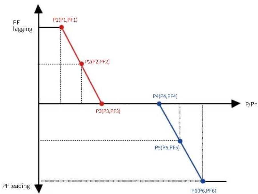
“PF(P)” Mode
| PFP Setting | |||
| Cut_in | 0.0% | Cut_out | 0.0% |
| P1 | 0.0% | PF1 | -1.000 |
| P2 | 0.0% | PF2 | -1.000 |
| P3 | 0.0% | PF3 | -1.000 |
| P4 | 0.0% | PF4 | -1.000 |
| P5 | 0.0% | PF5 | -1.000 |
| Back | |||
| PFP Setting | |||
| P6 | 0.0% | PF6 | -1.000 |
| Time | 0s | ||
| Back | |||
line
| Point | P/Pn | PF (P/L) | | :--- | :--- | :--- | | P1(P1,PF1) | Low | High | | P2(P2,PF2) | Medium | Medium-High | | P3(P3,PF3) | High | Low | | P4(P4,PF4) | High | Low | | P5(P5,PF5) | Medium | Medium | | P6(P6,PF6) | High | Low | The chart is divided into two sections: 'PF lagging' (left) and 'PF leading' (bottom). The red line represents a transition from high to low as P/L increases. The blue line represents a transition from low to high as P/N increases.Pic 8.29 Power factor Regulation Curve in PF(P) Mode
| Parameter Range Description | ||
| P1 | 0-110% Pn | Power value at point (PF1,P1) on the PF(P) Curve |
| PF1 | 0.8 leading - 0.8 lagging | PF value at point (PF1,P1) on the PF(P) Curve |
| P2 | 0-110% Pn | Power value at point (PF2,P2) on the PF(P) Curve |
| PF2 | 0.8 leading - 0.8 lagging | PF value at point (P2,PF2) on the PF(P) Curve |
| P3 | 0-110% Pn | Power value at point (P3,PF3) on the PF(P) Curve |
| PF3 | 0.8 leading - 0.8 lagging | PF value at point (P3,PF3) on the PF(P) Curve |
| P4 | 0-110% Pn | Power value at point (P4,PF4) on the PF(P) Curve |
| PF4 | 0.8 leading - 0.8 lagging | PF value at point (P4,PF4) on the PF(P) Curve |
| P5 | 0-110% Pn | Power value at point (P5,PF5) on the PF(P) Curve |
| PF5 | 0.8 leading - 0.8 lagging | PF value at point (P5,PF5) on the PF(P) Curve |
| P6 | 0-110% Pn | Power value at point (P6,PF6) on the PF(P) Curve |
| PF6 | 0.8 leading - 0.8 lagging | PF value at point (P6,PF6) on the PF(P) Curve |
| RMpTime | 0-1000s | The time of the PFF Curve in seconds (time to accomplish a change of 95%). |
"PF(P)" Mode Parameters Explanation
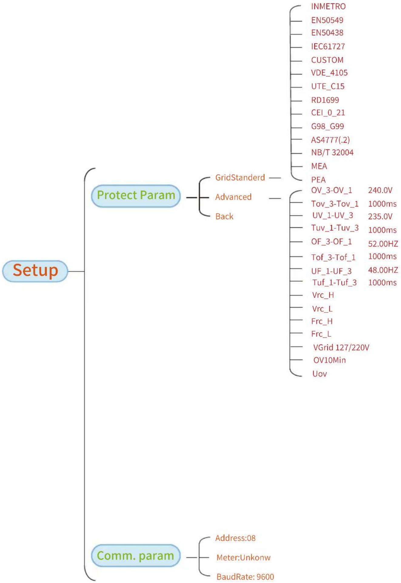
8.5.3 Protect Param
Australia-A
Australia-B
Australia-C
○ New Zealand
○ MEA
○ PEA
OK Cancel
Standard
○ Norway
○ Switzerland
R25
○ CEI-016
OK Cancel
Pic 8.31 "Standard"
| - VoltageTripping | |||
| OV_3 | 240.0V | Tov_3 | 1000ms |
| OV_2 | 240.0V | Tov_2 | 1000ms |
| OV_1 | 240.0V | Tov_1 | 1000ms |
| UV_1 | 240.0V | Tuv_1 | 1000ms |
| UV_2 | 240.0V | Tuv_2 | 1000ms |
| UV_3 | 240.0V | Tuv_3 | 1000ms |
| OK Cancel | |||
| - Frequency Tripping | |||
| OF_3 | 52.00Hz | Tof_3 | 1000ms |
| OF_2 | 52.00Hz | Tof_2 | 1000ms |
| OF_1 | 52.00Hz | Tof_1 | 1000ms |
| UF_1 | 48.00Hz | Tuf_1 | 1000ms |
| UF_2 | 48.00Hz | Tuf_2 | 1000ms |
| UF_3 | 48.00Hz | Tuf_3 | 1000ms |
| OK Cancel | |||
| - Miscellaneous | |||
| Vrc_H | 0.0V | Uov | 0.0% |
| Vrc_L | 0.0V | ||
| Frc_H | 0.0Hz | ||
| Frc_L | 0.0Hz | ||
| VGrid | 127/220V | ||
| OV10Min | OFF | ||
| OK Cancel | |||
Pic 8.32 "Advanced"
8.5.4 Comm. Param
| MENU》 Setup》 Comm.Param | |
| WIFI-SET | 485-SET |
| Address : 01《 | Address : 01 |
| Func : 485 | |
| Baud : 9600 | |
Pic 8.33 Communication param
9. Repair and Maintenance
String type inverter doesn’t need regular maintenance. However, debris or dust will affect heat sink’s thermal performance. It is better to clean it with a soft brush. If the surface is too dirty and affect the reading of LCD and LED lamp, you can use wet cloth to clean it up.

High Temperature Hazard:
When the device is running, the local temperature is too high and the touch can cause burns. Turn off the inverter and wait for it cooling, then you can clean and maintain.

Safety Hint:
No solvent, abrasive materials or corrosive materials can be used for cleaning any parts of the inverter.
10. Error information and processing
Inverter has been designed in accordance with international grid tied standards for safety, and electromagnetic compatibility requirements. Before delivering to the customer the inverter has been subjected to several tests to ensure its optimal operation and reliability.
10.1 Error code
If there is any failure, the LCD screen will display an alarm message. In this case, the inverter may stop feeding energy into the grid. The alarm description and their corresponding alarm messages are listed Table 10.1.
| Error code | Description Ongrid - Three Phase | |
| F01 DC input | polarity reverse fault Check the PV input polarity. | |
| F02 | DC insulation impedance permanent fault | Check the grounding cable of inverter. |
| F03 DC leakage current fault Hardly appear the code. Never ever happened so far. | ||
| F04 | Ground fault GFDI Check the solar panel output connection. | |
| F05 | Read the memory error | Failure in reading memory (EEPROM). Restart the inverter if the fault still exists, contact your installer or Deye service. |
| F06 | Write the memory error | Failure in writing memory (EEPROM). Restart the inverter if the fault still exists, contact your installer or Deye service. |
| F07 GFDI bown fuse Hardly appear the code. Never ever happened so far. | ||
| F08 GFDI grounding touch failure Hardly appear the code. Never ever happened so far. | ||
| F09 | IGBT damaged by excessive drop voltage | Hardly appear the code. Never ever happened so far. |
| F10 | Auxiliary switch power supply failure | 1. It tells the DC 12V is not existed.2. Restart the inverter, if the fault still exists, please contact your installer. |
| F11 AC main contactor errors Hardly appear the code. Never ever happened so far. | ||
| F12 AC auxiliary contactor errors Hardly appear the code. Never ever happened so far. | ||
| F13 | reserved | 1. Loss of one phase or AC voltage detection part failure or relays not closed.2. Restart the inverter, if the error still exists, please contact your installer or Deye service. |
| F14 DC firmware over current Hardly appear the code. Never ever happened so far. | ||
| F15 | AC firmware over current | 1. The internal AC sensor or detection circuit on control board or connection wire may loose.2. Restart the inverter, if the error still exists, please contact your installer or Deye service. |
| F16 | GFCI(RCD) Ac leakage current fault | 1. This fault means the average leakage current is over 300mA. Check whether DC power supply or solar panels is ok, then check 'Test data'-> 'diL' value is about 40; Then check the leakage current sensor or circuit (the following picture). Checking test data needs using big LCD.2. Restart the inverter, if the error still exists, please contact your installer or Deye service. |
| F17 | Three phase current, over-current fault | Hardly appear the code. Never ever happened so far. |
| F18 | AC over current fault of hardware | 1. Check AC sensor or detection circuit on control board or connection wire.2. Restart the inverter or factory reset, if the error still exists, please contact your installer or Deye service. |
| F19 | All hardware failure synthesis | Hardly appear the code. Never ever happened so far. |
| F20 | DC over current fault of the hardware | 1. Check whether solar panel output current is within the allowed range.2. Check DC current sensor and its detection circuit.3. Check if the inverter FW version is suitable for the hardware.4. Restart the inverter, if the error still exists, please contact your installer or Deye service. |
| F21 | Hardly appear the code. Never ever happened so far.DC leakage flow fault | |
| F22 | Crash stop (if there is a stop button) | Contact your installer for help. |
| F23 | AC leakage current is transient over current | This fault means the leakage current is above 30mA suddenly.Check whether DC power supply or solar panels is ok, then check 'Test data'-> 'diL value is about 40; Then check the leakage current sensor or circuit. Check test data needs using big LCD.Restart the inverter, if the fault still exists, contact your installer or Deye service. |
| F24 | DC insulation impedance failure | Check Vpe resistance on main board or detection on control board. Check PV panels is OK. Many times this issue is the PV problem.Check whether the PV panel (aluminum frame) is grounded well and inverter is grounded well. Open the cover of inverter and then check the inside ground cable is fixed well on the shell.Check if the AC/DC cable, terminal block are shorted to ground or the insulation is damaged.Restart the inverter, if the fault still exists, contact your installer or Deye service. |
| F25 DC feedback fault Hardly appear the code. Never ever happened so far. | ||
| F26 | The DC busbar is unbalanced | Check whether the 'BUSN' cable or driver board power supply cable is loose.Restart the inverter, if the fault still exists, contact your installer or Deye service. |
| F27 DC end insulation error Hardly appear the code. Never ever happened so far. | ||
| F28 Inverter 1 DC high fault Hardly appear the code. Never ever happened so far. | ||
| F29 AC load switch failure Hardly appear the code. Never ever happened so far. | ||
| F30 | AC main contactor failure | Check relays and AC voltage of relays.Check relays driver circuit. Check if the software is not suitable for this inverter. (Old inverter not have relays detection function)Restart the inverter, if the fault still exists, contact your installer or Deye service. |
| F31 | Relay open circuit fault | At least one Relay can't be closed. Check relays and its driver signal. (Old inverter not have relays detection function)Restart the inverter, if the fault still exists, contact your installer or Deye service. |
| F32 Inverter 2 dc high fault Hardly appear the code. Never ever happened so far. | ||
| F33 AC over current Hardly appear the code. Never ever happened so far. | ||
| F34 AC current over load Hardly appear the code. Never ever happened so far. | ||
| F35 | No AC grid | Check AC grid voltage. Check AC voltage detection circuit. Check if the AC connector in good condition. Check whether the AC grid is normal in voltage.Restart the inverter, if the fault still exists, contact your installer or Deye service. |
| F36 AC grid phase error Hardly appear the code. Never ever happened so far. | ||
| F37 | AC three-phase voltage unbalance failure | Hardly appear the code. Never ever happened so far. |
| F38 | AC three-phase current unbalance failure | Hardly appear the code. Never ever happened so far. |
| F39 | AC over current(one cycle) | 1. Check AC current sensor and its circuit.2. Restart the inverter, if the fault still exists, contact your installer or Deye service. |
| F40 DC over current | hardly appear the code. Never ever happened so far. | |
| F41 | AC Line W,U over voltage | Check the AC voltage protection setting. And Check if the AC cable is too thin.Check the voltage difference between LCD and meter. |
| F42 | AC Line W,U low voltage | Check the AC voltage protection setting. Check the voltage difference between LCD and meter. Also need to check whether AC cables are all firmly and correctly connected. |
| F43 | AC Line V,W over voltage | Check the AC voltage protection setting.And Check if the AC cable is too thin.Check the voltage difference between LCD and meter. |
| F44 | AC Line V,W low voltage | Check the AC voltage protection setting. Check the voltage difference between LCD and meter. Also need to check whether AC cables are all firmly and correctly connected. |
| F45 | AC Line U,V over voltage | Check the AC voltage protection setting.And Check if the AC cable is too thin.Check the voltage difference between LCD and meter. |
| F46 AC Line | U,V low voltage Check the AC voltage protection setting. | |
| F47 AC Over frequency | check the frequency protection setting. | |
| F48 AC lower frequency | check the frequency protection setting. | |
| F49 | U phase grid current DC component over current | Hardly appear the code. Never ever happened so far. |
| F50 | V phase grid current DC component over current | Hardly appear the code. Never ever happened so far. |
| F51 | W phase grid current DC component over current | Hardly appear the code. Never ever happened so far. |
| F52 | AC inductor A, phase current DC current high | Hardly appear the code. Never ever happened so far. |
| F53 | AC inductor B, phase current DC current high | Hardly appear the code. Never ever happened so far. |
| F54 | AC inductor C, phase current DC current high | Hardly appear the code. Never ever happened so far. |
| F55 | DC busbar voltage is too high | 1. Check PV voltage and Ubus voltage and its detection circuit. If the PV input voltage exceeds the limit, please reduce the number of solar panels in series.2. For Ubus voltage, please check the LCD display. |
| F56 | DC busbar voltage is too low | 1. It tells the PV input voltage is low and it always happens in the early morning.2. Check PV voltage and Ubus voltage. When inverter is running, then showing F56, maybe Loss of driver or need update firmware.3. Restart the inverter, if the fault still exists, contact your installer or Deye service. |
| F57 AC reverse irrigation AC reverse irrigation. | ||
| F58 AC grid | U over current Hardly appear the code. Never ever happened so far. | |
| F59 AC grid | V over current Hardly appear the code. | Never ever happened so far. |
| F60 AC grid | W over current Hardly appear the code. | Never ever happened so far. |
| F61 Reactor | A phase over current Hardly appear the code. | Never ever happened so far. |
| F62 Reactor | B phase over current Hardly appear the code. | Never ever happened so far. |
| F63 | ARC fault | 1. Check PV module cable connection and clear the fault;2. Seek help from us, if can not go back to normal state. |
| F64 | IGBT heat sink high temperature | 1. Check temperature sensor. Check if firmware is suitable for the hardware. Check if the inverter is its right model.2. Restart the inverter, if the fault still exists, contact your installer. |
Table10.1 Error codes and their solutions

Safety Hint:
If your string inverter has any of the fault information shown in Table 10-1, and when you reset the machine and still don’t solve the problem, please contact our distributor and provide the below details:
- Serial number of the inverter;
- The distributor/dealer of the inverter(if available);
- Installation date;
- The discription of problem(include LCD'error code and LED status indicator lights);
-
Your contact details.
-
Specification
| Model | SUN-25K-G02-LV SUN-30K-G02-LV | |
| Input Side | ||
| Max.DC Power(kW) | 32.5kW | 39kW |
| Max.DC Input Voltage(V) | 800V | |
| Start-up DC Input Voltage(V) | 250V | |
| MPPT Operating Range(V) | 200V-700V | |
| Rated DC input voltage(V) | 400V | |
| MPPT Full Power Voltage Range(V) | 250V-700V | |
| Max.DC Input Current(A) | 40A+40A+40A | 40A+40A+40A+40A |
| Max. Short Circuit Current (A) | 60A+60A+60A | 60A+60A+60A+60A |
| Number of MPPT/Strings per MPPT | 3/3+3+3 | 4/3+3+3+3 |
| MAX inverter backfeed current (A) | 0 | |
| Output Side | ||
| Rated Output Power(kW) | 25kW | 30kW |
| Max.Active Power(kW) | 27.5kW | 33kW |
| Rated AC Grid Voltage(V) | 3L/N/PE 127V/220V | |
| AC Grid Voltage Range(V) | 0.85Un-1.1Un (this may vary with grid standards) | |
| Rated Grid Frequency(Hz) | 50/60 (Optional) | |
| Operating Phase | Three phase | |
| Rated AC Grid Output Current(A) | 65.6A | 78.7A |
| Max.AC Output Current(A) | 72.2A | 86.6A |
| Maximum output fault current (a.c. A, peak) | 125.2A | 150.2A |
| Maximum output overcurrent protection (a.c. A,peak) | 139.1A | 166.9A |
| Output Power Factor | 0.8 leading to 0.8 lagging | |
| Grid Current THD | <3% | |
| DC Injection Current | <0.5% | |
| Grid Frequency Range | 45-55 or 55-65 (Optional) | |
| Efficiency | ||
| Max.Efficiency | 98.7% | |
| Euro Efficiency | 98% | |
| MPPT Efficiency | >99% | |
| Surge Protection | DC Type II / AC Type II | |
| General Data | ||
| Cabinet Size(W*H*D) [mm] | 647.5×537×303.5 (Excluding connectors and brackets) | |
| Weight(kg) | 44.5 | |
| Topology | Transformerless | |
| Internal consumption | <1W (Night) | |
| Operating temperature | -25 to +65°C,>45°C derating | |
| Ingress protection | IP65 | |
| Noise Emission(Typical) | ≤50 dB | |
| Type Of Cooling | Smart cooling | |
| Permissible Altitude (m) | 2000m | |
| Warranty [year] | Standard 5 years, extended warranty | |
| Grid Connection Standard | NBR 16149, NBR 16150, EN 50549, RD 140 | |
| Operation surrounding humidity | 0-100% | |
| Safety EMC / Standard | IEC/EN 61000-6-1/2/3/4, IEC/EN 62109-1, IEC/EN 62109-2 | |
| General Data | |
| LCD 240 × 160Display | |
| Interface RS485/RS232/Wifi/LAN | |
| Class IProtective Class | |
| Over Voltage Category III (AC), II (DC) | |
| Inverter Topology | Non-is olated |
| Pollution degree | PD2(Inside), PD3(Outside) |
12. EU Declaration of Conformity
within the scope of the EU directives
• Electromagnetic compatibility 2014/30/EU (EMC)
• Low Voltage Directive 2014/35/EU (LVD)
- Restriction of the use of certain hazardous substances 2011/65/EU(RoHS)

NINGBO DEYE INVERTER TECHNOLOGY CO.,LTD confirms herewith that the products described in this document are in compliance with the fundamental requirements and other relevant provisions of the above mentioned directives. The entire EU Declaration of Conformity can be found at www.deyeinverter.com.
Please scan the QR code to download the certification.

2023-09-26 Ver: 2.4
NINGBO DEYE INVERTER TECHNOLOGY CO., LTD.
Add: No.26 South YongJiang Road, Daqi, Beilun, NingBo, China.
Tel: +86 (0) 574 8622 8957
Fax: +86 (0) 574 8622 8852
E-mail: service@deye.com.cn
Web: www.deyeinverter.com

- Grid-connected PV Inverter
- User Manual
- Contents
- Introduction - 1 -
- Safety warnings and instructions ..... - 3 - ....
- Operation Interface -5-
- Product installation -7-
- Electrical Connection ...... - 11 -
- Startup and Shutdown - 18 -
- Zero-export function via energy meter - 19 -
- General Operation - 41 -
- Repair and Maintenance -69-
- Error information and processing -69-
- About This Manual
- How to Use This Manual
- Introduction
- Appearance Introduction
- Parts list
- Safety warnings and instructions
- Safety signs
- Warning:
- Shock Hazard:
- Safety Hint:
- High Temperature Hazard:
- Safety instructions
- Notes for using
- Operation Interface
- Interface View
- Status Indicator
- Buttons
- LCD Display
- Product installation
- Select installation location
- Mounting bracket of inverter
- Inverter Installation
- Electrical Connection
- DC input terminal connection
- AC terminal connection
- Recommended current protector specifications
- Connection of the ground line
- Inverter monitoring connection
- Installation of datalogger
- Configuration of datalogger
- Start up and Shut off
- Start up the inverter
- Shut off the inverter
- Zero-export function via energy meter
- Multiple strings and parallel connection meters
- How to browse the load power of your PV grid-tie plant on monitoring platform?
- General Operation
- The initial interface
- Main Menu
- Statistics information
- ON/OFF setting
- Parameter setting
- MENU》 Setup
- System Param
- MENU》 Setup \$ystem Param
- Time Set
- Language Set
- Display Set
- Factory data reset
- Run Param
- Over-frequency Response
- - "OFF" Mode
- - ReactiveP
- - "PF" Mode
- • "Q(U)" Mode
- • "Q(P)" Mode
- “Q(U)” Mode
- “Q(P)” Mode
- "Q(P)" Mode Parameters Explanation
- "PU" Mode
- "PU" Mode Parameters Explanation
- “PF(P)” Mode
- Protect Param
- Standard
- Comm. Param
- Repair and Maintenance
- Error information and processing
- Error code
- EU Declaration of Conformity
- NINGBO DEYE INVERTER TECHNOLOGY CO., LTD.
Brand : Deye
Model : SUN-25K-G04-LV
Category : Solar installation