SUN500G3-EU-230 - Solar installation Deye - Free user manual and instructions
Find the device manual for free SUN500G3-EU-230 Deye in PDF.


| Product Type | Solar Microinverter |
| Model | SUN500G3-EU-230 |
| Brand | Deye |
| Rated Output Power | 500 W |
| Nominal AC Voltage | 230 V |
| Grid Type | Single-phase |
| MPPT Voltage Range | 22 V - 50 V |
| Maximum Input Current | 13.5 A |
| Maximum Output Current | 2.2 A |
| Maximum Efficiency | 96.5% |
| Dimensions (W x H x D) | 280 x 200 x 42 mm |
| Weight | 2.5 kg |
| Enclosure Rating | IP67 |
| Cooling Method | Natural Convection |
| Operating Temperature | -40°C to +65°C |
| Safety Features | Overvoltage, Overcurrent, Anti-Islanding, Ground Fault Protection |
| Communication | Wi-Fi / Zigbee (optional) |
| Compliance | VDE-AR-N 4105, EN 50549, IEC 62109 |
| Warranty | 12 years standard |
| Maintenance | Keep clean with dry cloth; no water or solvents |
| Spare Parts Availability | Contact authorized dealer for replacement parts |
Frequently Asked Questions - SUN500G3-EU-230 Deye
User questions about SUN500G3-EU-230 Deye
0 question about this device. Answer the ones you know or ask your own.
Ask a new question about this device
Download the instructions for your Solar installation in PDF format for free! Find your manual SUN500G3-EU-230 - Deye and take your electronic device back in hand. On this page are published all the documents necessary for the use of your device. SUN500G3-EU-230 by Deye.
USER MANUAL SUN500G3-EU-230 Deye
Installation/UserManual
Photovoltaic Grid-connected Microinverter(Built-in WIFI-G3)
natural_image
Abstract curved lines forming concentric arcs (no text or symbols)Ver:1.2, 2020-10
502011646
Table of Contents
Important Safety Instructions 01-03
Safety Instructions
Radio Interference Statement
The Meaning of Symbols
Microinverter System Introduction 03-05
Microinverters Maximize PV Energy Production
More Reliable than Centralized or String Inverters
Simple to Install
Microinverter Introduction 05
Microinverter System Installation 06-09
Additional Installation Components
Required Parts and Tools from You
Installation Procedures
Microinverter System Operating Instructions 09-10
Troubleshooting 10-12
Status Indications and Error Reporting
Troubleshooting a Non-operating Microinverter
Replacement 13
Technical Data 14-16
300/500/600/800/1000G3 Microinverter Datasheet
1300/1600/2000G3 Microinverter Datasheet
Wiring Diagram 17-20
Monitoring Platform 21
Important Safety Instructions
This manual contains important instructions to follow during installation and maintenance of the Photovoltaic Grid-connected Inverter(Microinverter). To reduce the risk of electrical shock and ensure the safe installation and operation of the Microinverter, the following symbols appear throughout this document to indicate dangerous conditions and important safety instructions.
Specifications subject to change without notice - please ensure you are using the latest manual found at the manufacturer website.
WARNING: This indicates a situation where failure to follow instructions may cause a serious hardware failure or personnel danger if not applied appropriately. Use extreme caution when performing this task.
NOTE: This indicates information that is important for optimized microinverter operation. Follow these instructions strictly.
Safety Instructions
√ DO NOT disconnect the PV module from the Microinverter without disconnecting the AC power.
√ Only qualified professionals should install and/or replace the Microinverters.
√ Perform all electrical installations in accordance with local electrical codes.
√ Before installing or using the Microinverter, please read all instructions and cautionary markings in the technical documents and on the Microinverter system and the solar-array.
√ Be aware that the body of the Microinverter is the heat sink and can reach a temperature of 80^ C. To reduce risk of burns, do not touch the body of the Microinverter.
√ DO NOT attempt to repair the Microinverter. If it fails, contact technical support to obtain an RMA number and start the replacement process. Damaging or opening the Microinverter will void the warranty.
√ Caution!
The external protective earthing conductor is connected to the inverter protective earthing terminal through AC connector.
When connecting, connect the AC connector first to ensure the inverter earthing then do the DC connections.
When disconnecting, disconnect the AC by opening the branch circuit breaker first
but maintain the protective earthing conductor in the branch circuit breaker connect to the inverter, then disconnect the DC inputs.
√ In any circumstance, do not connect DC input when AC connector is unplugged.
√ Please install isolation switching devices on the AC side of the inverter.
Radio Interference Statement
CE EMC Compliance: The equipment can comply with CE EMC, which are designed to protect against harmful interference in a residential installation. The equipment could radiate radio frequency energy and this might cause harmful interference to radio communications if not following the instructions when installing and using the equipment. But there is no guarantee that interference will not occur in a particular installation. If this equipment causes harmful interference to radio or television reception, the following measures might resolve the issues:
A) Relocate the receiving antenna and keep it well away from the equipment.
B) Consult the dealer or an experienced radio / TV technical for help.
Changes or modifications not expressly approved by the party responsible for compliance may void the user's authority to operate the equipment.
The Meaning of Symbols
| Can be OEM Trademark. | |
 | Caution, risk of electric shock. |
 | Caution, risk of burn - Do not touch. |
 | Caution, hot surface. |
  | Symbol for the marking of electrical and electronics devices according to Directive 2002/96/EC. Indicates that the device, accessories and the packaging must not be disposed as unsorted municipal waste and must be collected separately at the end of the usage. Please follow Local Ordinances or Regulations for disposal or contact an authorized representative of the manufacturer for information concerning the decommissioning of equipment.CE mark is attached to the solar inverter to verify that the unit follows the provisions of the European Low Voltage and EMC Directives. |
 | Refer to the operating instructions. |
| Qualified personnel | Person adequately advised or supervised by an electrically skilled person to enable him or her to perceive risks and to avoid hazards which electricity can create. For the purpose of the safety information of this manual, a "qualified person" is someone who is familiar with requirements for safety, refrigeration system and EMC and is authorized to energize,ground, and tag equipment, systems, and circuits in accordance with established safety procedures. The inverter and endues system may only be commissioned and operated by qualified personnel. |
Microinverter System Introduction
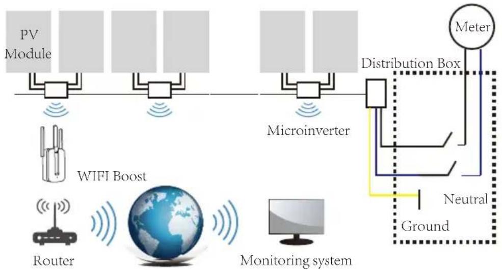
The Microinverter is used in utility-interactive grid-tied applications, comprised of two key elements:
- Microinverter
- Router
300 / 500 / 600 / 800 / 1000G3
flowchart
graph TD
    A["PV Module"] --> B["Microinverter"]
    B --> C["Distribution Box"]
    C --> D["Meter"]
    D --> E["Neutral Ground"]
    F["WIFI Boost"] --> G["Router"]
    G --> H["Global"]
    H --> I["Monitoring system"]
    I --> J["Monitor System"]
    style A fill:#f9f,stroke:#333
    style B fill:#f9f,stroke:#333
    style C fill:#ccf,stroke:#333
    style D fill:#cfc,stroke:#333
    style E fill:#fcc,stroke:#333
    style F fill:#ffc,stroke:#333
    style G fill:#cfc,stroke:#333
    style H fill:#fcc,stroke:#333
    style I fill:#cfc,stroke:#333
    style J fill:#fcc,stroke:#333
1300 / 1600 / 1800 / 2000G3
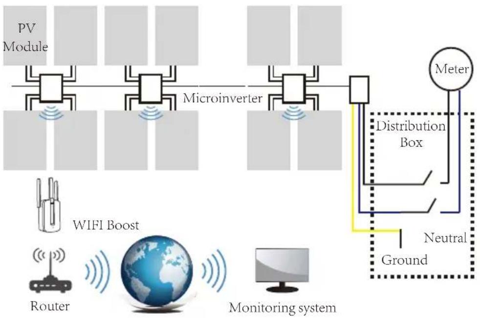
flowchart
graph TD
    A["PV Module"] --> B["Microinverter"]
    B --> C["Distribution Box"]
    C --> D["Meter"]
    D --> E["Neutral Ground"]
    E --> F["Monitoring system"]
    F --> G["Router"]
    G --> H["WIFI Boost"]
    H --> A
NOTE: If the wireless signal in the area where the microinverter is weak is weak, it is necessary to add a wifi signal booster at a suitable place between the router and the microinverter.
This integrated system improves safety; maximizes solar energy harvest; increases system reliability, and simplifies solar system design, installation, maintenance, and management.
Microinverters Maximize PV Energy Production
Each PV module has individual Maximum Peak Power Tracking (MPPT) controls, which ensures that the maximum power is exported to the utility grid regardless of the performance of the other PV modules in the array. When PV modules in the array are affected by shade, dust, orientation, or any situation in which one module underperforms compared with the other units, the Microinverter ensures top performance from the array by maximizing the performance of each module within the array.
More Reliable than Centralized or String Inverters
The distributed Microinverter system ensures that no single point of system failure exists across the PV system. Microinverters are designed to operate at full power at ambient outdoor temperatures of up to 149 F (65°C). The inverter housing is designed for outdoor installation and complies with the IP65 environmental enclosure rating.
Simple to Install
You can install individual PV modules in any combination of Module quantity, orientation, different type and power rate The Ground wire (PE) of the AC cable is connected to the chassis inside of the Microinverter, potentially eliminating the installation of grounding wire (check local regulation).
Data collection adopts internal wifi, wireless router is needed near the microinverter. When complete the installation of microinverter, configure wireless router with internal wifi (refer to the wifi user manual). The data will be uploaded automatically. Users can monitor and manage the microinverter through corresponding website or APP.
Microinverter Introduction
The Microinverters connect with the single-phase grid, and can also use multiple Microinverters in the form of single-phase grid to achieve three-phase grid.
For more information, please see the Technical Data page (P17\~20) of this manual.
| Model Number | AC grid | Max. # Per branch |
| SUN300G3-EU-230 50/60Hz, 230V | 17 for 25A breaker | |
| SUN500G3-EU-230 50/60Hz, 230V 10 for 25A breaker | ||
| SUN600G3-EU-230 50/60Hz, 230V 8 for 25A breaker | ||
| SUN800G3-EU-230 50/60Hz, 230V 6 for 25A breaker | ||
| SUN1000G3-EU-230 50/60Hz, 230V | 5 for 25A breaker | |
| SUN1300G3-EU-230 50/60Hz, 230V 4 for 25A breaker | ||
| SUN1600G3-EU-230 50/60Hz, 230V 4 for 45A breaker | ||
| SUN1800G3-EU-230 50/60Hz, 230V 3 for 45A breaker | ||
| SUN2000G3-EU-230 50/60Hz, 230V 3 for 45A breaker | ||
Microinverter System Installation
A PV system using Microinverters is simple to install. Each Microinverter easily mounts on the PV racking, directly beneath the PV module(s). Low voltage DC wires connect from the PV module directly to the Microinverter, eliminating the risk of high DC voltage. Installation MUST comply with local regulations and technical rules.
Special Statement! An AC GFCI device should not be used to protect the dedicated circuit to the microinverter even though it is an outside circuit. None of the small GFCI devices (5\~30mA) are designed for back feeding and will be damaged if back feed. In a similar manner, AC AFCIs have not been evaluated for back feeding and may be damaged if back feed with the output of a PV inverter.
WARNING: Perform all electrical installations in accordance with local electrical codes.
WARNING: Be aware that only qualified professionals should install and/or replace Microinverters.
WARNING: Before installing or using an Microinverter, please read all instructions and warnings in the technical documents and on the Microinverter system itself as well as on the PV array.
WARNING: Be aware that installation of this equipment includes the risk of electric shock.
WARNING: Do not touch any live parts in the system, including the PV array, when the system has been connected to the electrical grid.
NOTE: Strongly recommend to install Surge protection Devices in the dedicated meter box.
Additional Installation components
• AC Male and Female Interconnection Connectors (sold separately)
• Sealing end caps(sold separately)
Required Parts and Tools from you
In addition to your PV array and its associated hardware, you will need the following items:
• An AC connection junction box
- Mounting hardware suitable for module racking
- Sockets and wrenches for mounting hardware
• Continuous grounding conductor and grounding washers
• A Phillips screwdriver
• A torque wrench
Installation Procedures
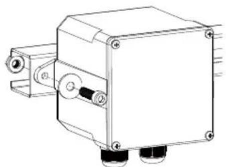
Step 1 - Install the AC branch circuit junction box
natural_image
Technical line drawing of a mechanical device with mounting brackets and a central housing (no text or symbols)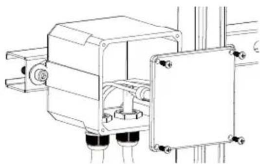
natural_image
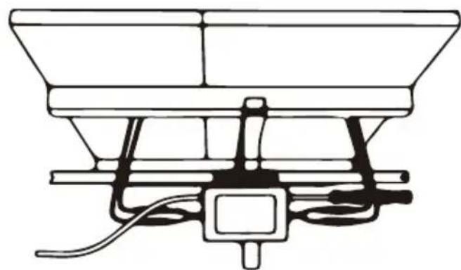
Technical line drawing of a mechanical assembly with mounting brackets and cylindrical components (no text or symbols)a. Install an appropriate junction box at a suitable location on the PV racking system (typically at the end of a branch of modules).
b. Connect the open wire end of the AC cable into the junction box using an appropriate gland or strain relief fitting.
c. Wire the conductors of the AC(230/400Vac): L - red; N - black ;PE - yellow green.
d. Connect the AC branch circuit junction box to the point of utility Interconnection.
WARNING: Wiring colour code can be different according local regulation, check all the wires of the installation before connecting to the AC cable to be sure they match. Wrong cabling can damage irreparably the microinverters, such an issue is not covered by the warranty.
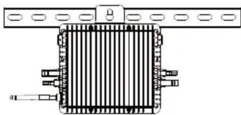
Step 2 - Attach the Microinverters to the racking or the PV module frame
a. Mark the location of the Microinverter on the rack, with respect to the PV module junction box or any other obstructions.
b. Mount one Microinverter at each of these locations using hardware recommended by your module racking vendor.
natural_image
Pure electrical circuit lines without any symbols300 / 500G3 (1MPPT) 600 / 800 / 1000G3 (2MPPT) Mounting
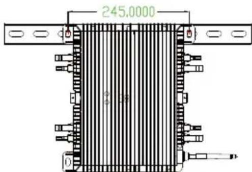
1300 / 1600 / 2000G3 (4MPPT) Mounting
WARNING: Prior to installing any of the microinverters, verify that the utility voltage at the point of common connection matches the voltage rating on microinverter label.
WARNING: Do not place the inverters (including DC and AC connectors) where exposed to the sun, rain or snow, even gap between modules. Allow a minimum of 3/4 (1.5cm.) between the roof and the bottom of the Microinverter to allow proper air flow.
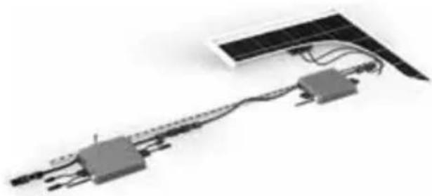
Step 3 - Connect the microinverters in parallel
natural_image
Pure electrical circuit lines without any symbols300/500G (1MPPT)
600/800/1000G3 (2MPPT)
connect in parallel
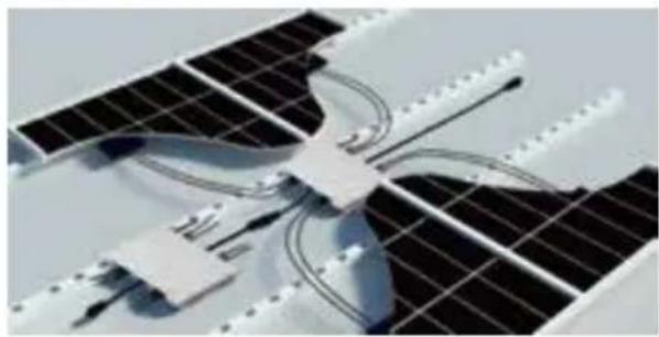
natural_image
Close-up of a solar panel with visible internal components and wiring (no text or symbols)1300/1600/2000G3 (4MPPT)
connect in parallel
a. Check the Microinverter technical data page 5 for the maximum allowable number of Microinverters on each AC branch circuit.
b. Plug the male AC connector of the Microinverter into the female connector to get it connected. AC connector interface as follows.
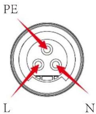
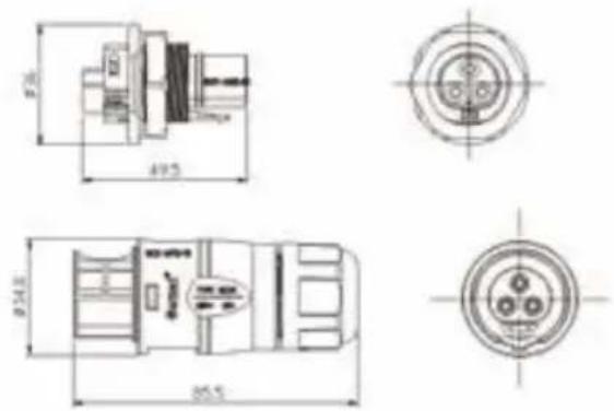
WARNING: DO NOT exceed maximum number of Microinverters in an AC branch circuit, as displayed on the page 5 of this manual.
Step 4 - Install an AC cable protective end cap at the end of AC cable
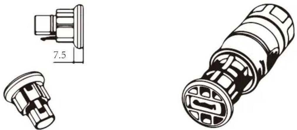
Step 5 - Connect Microinverter to the PV Modules
natural_image
Technical line drawing of a mechanical assembly with no visible text or symbols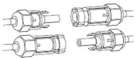
natural_image
Technical line drawings of four different mechanical or electronic component assemblies (no text or symbols)NOTE: When plugging in the DC cables, if AC already available, the Microinverter should immediately blink red light and will start work within the setting time (default 60 seconds). If AC is not available, the red light will blink 3 times quickly and repeat after one second until AC is connected.
Microinverter System Operating Instructions
To operate the microinverter PV system:
-
Turn ON the AC circuit breaker on each microinverter AC branch circuit.
-
Turn ON the main utility-grid AC circuit breaker. Your system will start producing power after a one-minute waiting time.
-
The units should start blinking red one minutes after turning on the AC circuit breaker. Then blue led blinking. This means they are producing power normally, the faster blinking of the blue led means more power generated.
- Configure the internal wifi module according to its user manual.
- The Microinverters will start to send performance data over wifi module to the network every 5 minutes. It enables customers to monitor performance data of each microinverter through website and APP.
NOTE: When AC power is applied but the microinverter not started up, about 0.1A current and 25VA(W) power for each microinverter may be measured by a power meter. This power is reactive power, not consume from utility grid.
Troubleshooting
Qualified personnel can use the following troubleshooting steps if the PV system does not operate correctly:
Status Indications and Error Reporting
Start up LED
One minute after DC power is first applied to the microinverter, one short red blinks indicate a successful microinverter startup sequence, be equal or greater than two short red blinks after DC power is first applied to the microinverter indicate a failure during microinverter setup.
Operation LED
Flashing Slow Blue - Producing small power Flashing Fast Blue - Producing big power Flashing Red - Not producing power Red blinking two times - AC low-voltage or high-voltage Red blinking three times - Grid failure
GFDI Error
A four time red LED indicates the Microinverter has detected a Ground Fault Detector Interrupter (GFDI) error in the PV system. Unless the GFDI error has been cleared, the LED will remain four times blinking.
Other Faults
All other faults can be reported to the website and APP.
WARNING: Never disconnect the DC wire connectors under load. Ensure that no current is flowing in the DC wires prior to disconnecting. An opaque covering may be used to cover the module prior to disconnecting the module.
Troubleshooting a non-operating Microinverter
There are two possible overall areas of trouble:
A. The Microinverter itself may be having problems.
B. The Microinverter itself is working fine but the communication between microinverter and network has problem. The items below refer to Microinverter issues, not communicat-ion issues:
One quick way to tell whether the issue is the Microinverter or the communication problem:
- Diagnosing from the Microinverter: A red light - either blinking or solid on the Microinverter, or no light at all means it is definitely the Microinverter problem.
-
0 watts, or 2 watts: Possibly a Microinverter problem
-
Diagnosing from the network:
a. No-Data-Display: The website and APP don't display any data. Check the network configuration.
b. Only display microinverter is online but no data. This may be because server is updating.
To troubleshoot a non-operating Microinverter, Follow the steps below in order:
- Verify the utility voltage and frequency are within ranges shown in the Technical Data section of this manual.
- Check the connection to the utility grid.Disconnect AC firstly,then disconnect DC and make sure the utility grid voltage can be measured at AC connector. Never disconnect the DC wires while the microinverter is producing power. Re-connect the DC module connectors and watch for three short LED flashes.
- Check the AC branch circuit interconnection between all the microinverters. Verify each inverter is energized by the utility grid as described in the previous step.
- Make sure that any AC breaker are functioning properly and are closed.
- Check the DC connections between the microinverter and the PV module.
- Verify the PV module DC voltage is within the allowable range shown in the Technical Data of this manual.
- If the problem still persists, please contact technical support.
WARNING: Do not attempt to repair the microinverter. If troubleshooting methods fail, please call for Technical Support
Replacement
Follow the procedure to replace a failed Microinverter
A. Disconnect the Microinverter from the PV Module, in the order shown below:
- Disconnect the AC by turning off the branch circuit breaker.
- Disconnect the AC connector of the microinverter.
- Cover the module with an opaque cover.
- Disconnect the PV module DC wire connectors from the Microinverter.
- Remove the Microinverter from the PV array racking.
B. Remove the opaque cover, Install a replaced Microinverter to the bracket.
Remember to observe the flashing LED light as soon as the new Microinverter is plugged into the DC cables.
C. Connect the AC cable of the replacement Microinverter.
Technical Data
WARNING: Be sure to verify the voltage and current specifications of your PV module match with those of the Microinverter. Please refer to the datasheet or user manual.
WARNING: You must match the DC operating voltage range of the PV module with the allowable input voltage range of the Microinverter.
WARNING: The maximum open circuit voltage of the PV module must not exceed the specified maximum input voltage of the inverter.
300G3/500G3/600G3 Microinverter Datasheet
| Model | SUN300G3-EU-230 | SUN500G3-EU-230 | SUN600G3-EU-230 |
| Input Data (DC) | |||
| Recommended input power(STC) | 210~600W | 210~400W | 210~400W |
| Maximum input DC voltage 60V | |||
| MPPT Voltage Range | 25~55V | ||
| Operating DC Voltage Range | 20~60V | ||
| Max DC short circuit current | 16A16A 16A | ||
| Max input current | 10.5A×1 12.5A×1 10.5A×2 | ||
| Output Data (AC) | |||
| Rated output Power | 300W | 500W | 600W |
| Maximum output power | 330W | 550W | 660W |
| Maximum output Current | 2.4A1.4A 2.9A | ||
| Nominal voltage / range | 230V / 184-265V | ||
| Nominal frequency | 50/60Hz | ||
| Extended frequency / range | 45~55Hz/ 55~65Hz | ||
| Power factor | >0.99 | ||
| Maximum unit per branch | 17 10 | 8 | |
| Max. allowed altitude operating | <4000m | ||
| Max.inverter backfeed current to the array | 0A | ||
| Max output fault current | 10A | ||
| Max output overcurrent protection | 1.4A 2.4A 2.9A | ||
| Efficiency | |||
| CEC weighted efficiency | 95% | ||
| Peak inverter efficiency | 96.5% | ||
| Static MPPT efficiency | 99% | ||
| Night time power consumption | 50mW | ||
| Mechanical Data | |||
| Ambient temperature range | -40 °C ~ +65 °C | ||
| Dimensions(W×H×D mm) | 212×229×40 mm (Does not include cable) | ||
| Weight (kg) | 3.5 | ||
| Cooling | Natural Convection - No Fans | ||
| Enclosure environmental rating | IP67 | ||
| Protective class | Class I | ||
| Features | |||
| Compatibility | Compatible with 60,72 cell PV modules | ||
| Communication | Power line / WiFi / Zigbee | ||
| Compliance | EN50549,VDE0126,VDE4105,IEC62109,CE,INMETRO | ||
| Warranty | 10 Years | ||
800G3/1000G3 Microinverter Datasheet
| Model | SUN800G3-EU-230 | SUN1000G3-EU-230 |
| Input Data (DC) | ||
| Recommended input power(STC) 210~600W | ||
| Maximum input DC voltage 60V | ||
| MPPT Voltage Range | 25~55V | |
| Operating DC Voltage Range | 20~60V | |
| Max DC short circuit current | 16A | |
| Max input current | 12.5A×2 | |
| Output Data (AC) | ||
| Rated output Power | 1000W800W | |
| Maximum output power | 880W | 1100W |
| Maximum output Current | 3.8A 4.8A | |
| Nominal voltage / range | 230V / 184-265V | |
| Nominal frequency | 50/60Hz | |
| Extended frequency / range | 45~55Hz/ 55~65Hz | |
| Power factor | >0.99 | |
| Maximum unit per branch | 6 | 5 |
| Max. allowed altitude operating | <4000m | |
| Max.inverter backfeed current to the array | 0A | |
| Max output fault current | 10A | |
| Max output overcurrent protection | 3.8A 4.8A | |
| Efficiency | ||
| CEC weighted efficiency | 95% | |
| Peak inverter efficiency | 96.5% | |
| Static MPPT efficiency | 99% | |
| Night time power consumption | 50mW | |
| Mechanical Data | ||
| Ambient temperature range | -40 °C ~ +65 °C | |
| Dimensions(W×H×D mm) | 212×229×40 mm (Does not include cable) | |
| Weight (kg) | 3.5 | |
| Cooling | Natural Convection - No Fans | |
| Enclosure environmental rating | IP67 | |
| Protective class | Class I | |
| Features | ||
| Compatibility | Compatible with 60,72 cell PV modules | |
| Communication | Power line / WiFi / Zigbee | |
| Compliance | EN50549,VDE0126,VDE4105,IEC62109,CE,INMETRO | |
| Warranty | 10 Years | |
1300G3/1600G3/1800G3/2000G3 Microinverter Datasheet
| Model | SUN1300G3-EU-230 | SUN1600G3-EU-230 | SUN1800G3-EU-230 | SUN2000G3-EU-230 |
| Input Data (DC) | ||||
| Recommended input power(STC) | 210~600W | 210~600W | 210~400W | 210~600W |
| Maximum input DC voltage 60V | ||||
| MPPT Voltage Range | 25~55V | |||
| Operating DC Voltage Range | 20~60V | |||
| Max DC short circuit current | 16A | |||
| Max input current | 12.5A×4 | 12.5A | 12.5A×4 | |
| Output Data (AC) | ||||
| Rated output Power | 1600W | 1300W | 1800W | 2000W |
| Maximum output power | 1430W | 1760W | 1980W | 2200W |
| Maximum output Current | 6.2A | 7.7A | 9.6A | 8.6A |
| Nominal voltage / range | 230V / 184-265V | |||
| Nominal frequency | 50/60Hz | |||
| Extended frequency / range | 45~55Hz/ 55~65Hz | |||
| Power factor | >0.99 | |||
| Maximum unit per branch | 4 4 33 | |||
| Max. allowed altitude operating | <4000m | |||
| Max.inverter backfeed current to the array | 0A | |||
| Max output fault current | 10A | |||
| Max output overcurrent protection | 6.2A | 7.7A | 9.6A | 8.6A |
| Efficiency | ||||
| CEC weighted efficiency | 95% | |||
| Peak inverter efficiency | 96.5% | |||
| Static MPPT efficiency | 99% | |||
| Night time power consumption | 50mW | |||
| Mechanical Data | ||||
| Ambient temperature range | -40 °C ~ +65 °C | |||
| Dimensions(W×H×D mm) | 267×300×42.5 mm (Does not include cable) | |||
| Weight (kg) | 5.2 | |||
| Cooling | Natural Convection - No Fans | |||
| Enclosure environmental rating | IP67 | |||
| Protective class | Class I | |||
| Features | ||||
| Compatibility | Compatible with 60,72 cell PV modules | |||
| Communication | Power line / WiFi / Zigbee | |||
| Compliance | EN50549,VDE0126,VDE4105,IEC62109,CE,INMETRO | |||
| Warranty | 10 Years | |||
Wiring Diagram
Sample Wiring Diagram Three Phase
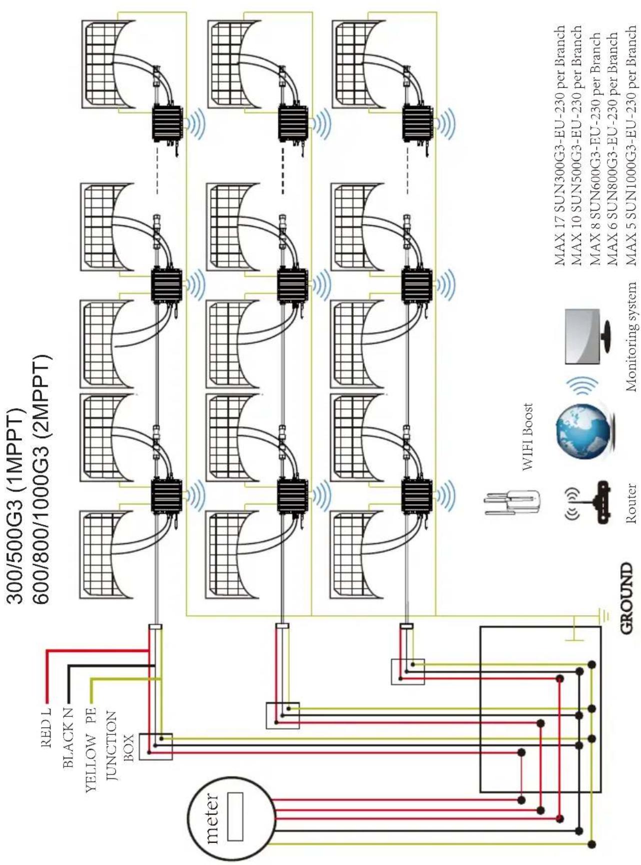
flowchart
graph TD
    A["meter"] --> B["300/500G3 (1MPPT)"]
    A --> C["600/800/1000G3 (2MPPT)"]
    B --> D["Network"]
    C --> D
    D --> E["Router"]
    D --> F["Monitoring system"]
    style A fill:#f9f,stroke:#333
    style B fill:#ccf,stroke:#333
    style C fill:#ccf,stroke:#333
    style D fill:#cfc,stroke:#333
    style E fill:#fcc,stroke:#333
    style F fill:#fcc,stroke:#333
    subgraph Network
        G["Network"]
        H["300/500G3 (1MPPT)"]
        I["600/800/1000G3 (2MPPT)"]
    end
    J["Ground"] --> K["WIFI Boost"]
    L["Router"] --> M["Monitor system"]
    N["Monitoring system"] --> M
    style J fill:#fff,stroke:#333
    style K fill:#fff,stroke:#333
    style M fill:#fff,stroke:#333
    note right of J "meter"
        MAX 17 SUN300G3-EU-230 per Branch
        MAX 10 SUN500G3-EU-230 per Branch
        MAX 8 SUN600G3-EU-230 per Branch
        MAX 6 SUN800G3-EU-230 per Branch
        MAX 5 SUN1000G3-EU-230 per Branch
    end
Sample Wiring Diagram Single Phase
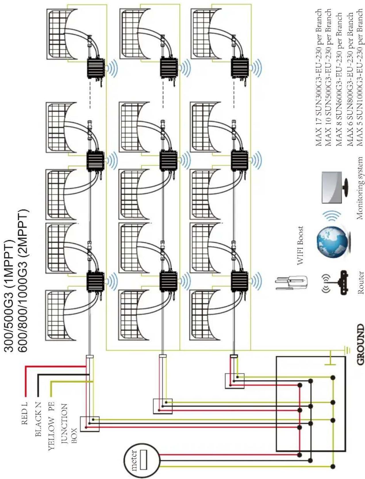
flowchart
graph TD
    A["meter"] --> B["300/500G3 (1MPPT)"]
    A --> C["600/800/1000G3 (2MPPT)"]
    B --> D["Network"]
    C --> D
    D --> E["Router"]
    D --> F["Monitoring system"]
    E --> G["WIFI Boost"]
    F --> G
    style A fill:#f9f,stroke:#333
    style B fill:#ccf,stroke:#333
    style C fill:#ccf,stroke:#333
    style D fill:#cfc,stroke:#333
    style E fill:#fcc,stroke:#333
    style F fill:#fcc,stroke:#333
    style G fill:#ffc,stroke:#333
Sample Wiring Diagram Three Phase
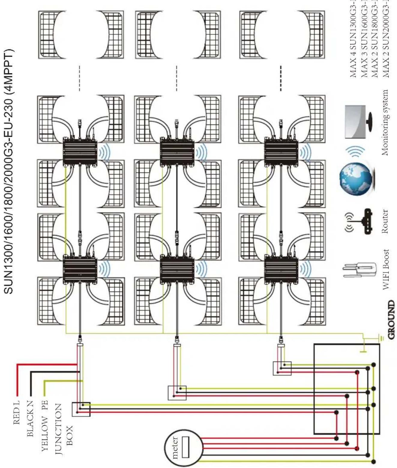
flowchart
graph TD
    A["meter"] --> B["RED L"]
    A --> C["BLACK N"]
    A --> D["YELLOW PE"]
    A --> E["JUNCTION BOX"]
    B --> F["Network Diagram"]
    C --> F
    D --> F
    E --> F
    F --> G["Grid of Sensors"]
    G --> H["WIFI Boost"]
    G --> I["Router"]
    G --> J["Monitoring System"]
    H --> K["SUN1300G3-"]
    I --> L["SUN1600G3-"]
    J --> M["SUN1800G3-"]
    K --> N["SUN2000G3-"]
    L --> N
    M --> N
    style A fill:#f9f,stroke:#333
    style B fill:#ccf,stroke:#333
    style C fill:#ccf,stroke:#333
    style D fill:#ccf,stroke:#333
    style E fill:#ccf,stroke:#333
    style F fill:#cfc,stroke:#333
    style G fill:#fcc,stroke:#333
    style H fill:#ffc,stroke:#333
    style I fill:#ffc,stroke:#333
    style J fill:#ffc,stroke:#333
    style K fill:#cfc,stroke:#333
    style L fill:#cfc,stroke:#333
    style M fill:#cfc,stroke:#333
    style N fill:#cfc,stroke:#333
Sample Wiring Diagram Single Phase
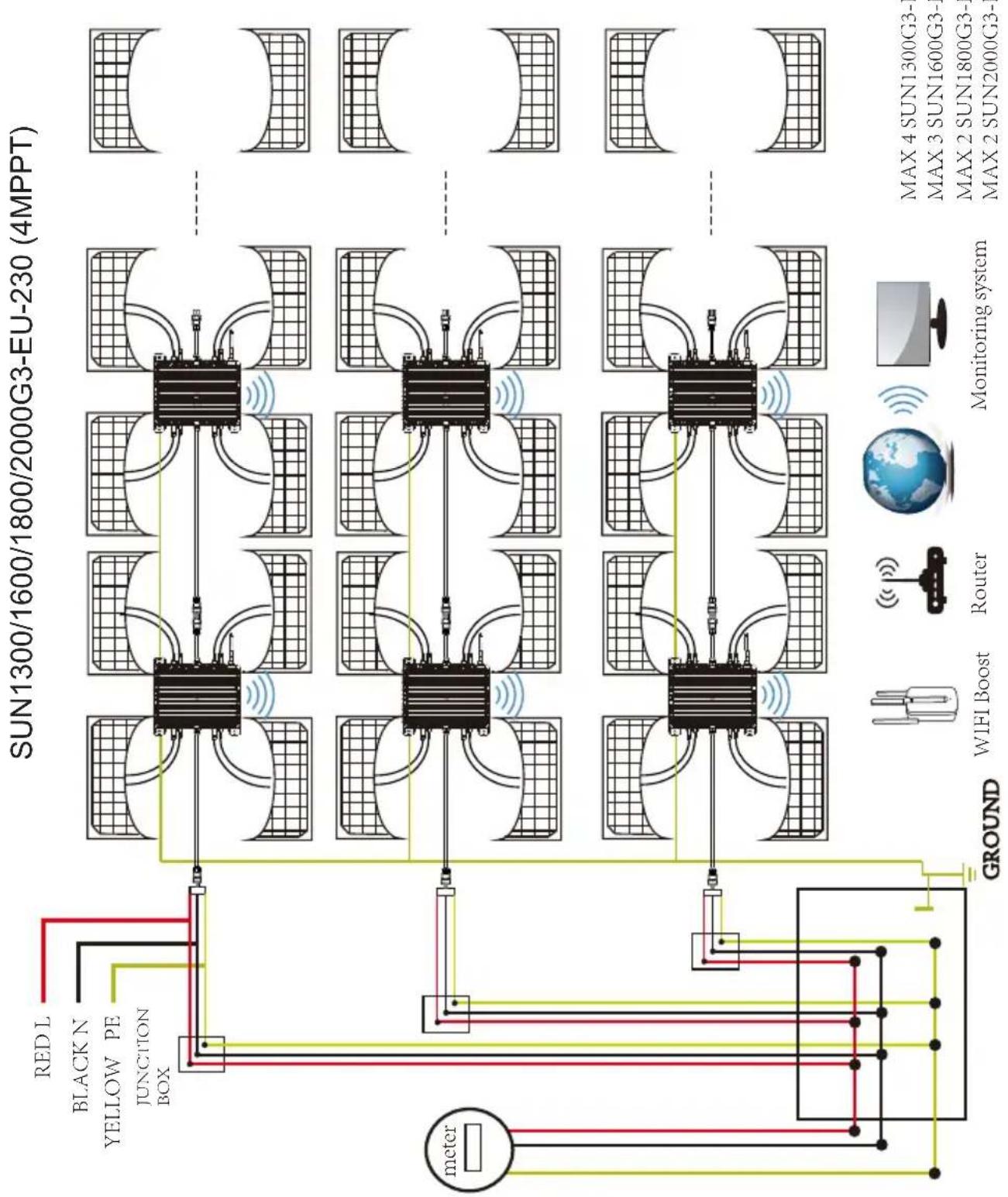
flowchart
graph TD
    A["meter"] --> B["RED L"]
    A --> C["BLACK N"]
    A --> D["YELLOW PE"]
    A --> E["JUNCTION BOX"]
    B --> F["Network Diagram"]
    C --> F
    D --> F
    E --> F
    F --> G["Network Diagram with Sensors"]
    G --> H["Monitoring System"]
    H --> I["WIFI Boost"]
    H --> J["Router"]
    H --> K["MAX 4 SUN1300G3-"]
    H --> L["MAX 3 SUN1600G3-"]
    H --> M["MAX 2 SUN1800G3-"]
    H --> N["MAX 2 SUN2000G3-"]
Monitoring Platform
This series microinverter has built-in WIFI modular which is able to connect router directly. For WIFI configuration, please check the manual of “Built-in WIFI modular microinverter WIFI configuration Manual”
Web monitoring address: https://pro.solarmanpv.com; (for Solarman distributor account)
https://home.solarmanpv.com (for Solarman end user account)
For mobile phone monitoring system, scan the QR code to download the APP. Also, you could find it by searching “solarman” in App store or Google Play.

IOS/Android system for plant owner account

IOS/Android system for distributor account
- Installation/UserManual
- Photovoltaic Grid-connected Microinverter(Built-in WIFI-G3)
- Table of Contents
- Important Safety Instructions 01-03
- Microinverter System Introduction 03-05
- Microinverter Introduction 05
- Microinverter System Installation 06-09
- Microinverter System Operating Instructions 09-10
- Troubleshooting 10-12
- Replacement 13
- Technical Data 14-16
- Wiring Diagram 17-20
- Monitoring Platform 21
- Important Safety Instructions
- Safety Instructions
- Radio Interference Statement
- The Meaning of Symbols
- Microinverter System Introduction
- Microinverters Maximize PV Energy Production
- More Reliable than Centralized or String Inverters
- Simple to Install
- Microinverter Introduction
- Microinverter System Installation
- Additional Installation components
- Required Parts and Tools from you
- Installation Procedures
- Microinverter System Operating Instructions
- To operate the microinverter PV system:
- Troubleshooting
- Status Indications and Error Reporting
- Start up LED
- Operation LED
- GFDI Error
- Other Faults
- Troubleshooting a non-operating Microinverter
- To troubleshoot a non-operating Microinverter, Follow the steps below in order:
- Replacement
- Follow the procedure to replace a failed Microinverter
- Technical Data
- Wiring Diagram
- Monitoring Platform
Brand : Deye
Model : SUN500G3-EU-230
Category : Solar installation