
HB24FS - Freezer Perlick - Free user manual and instructions
Find the device manual for free HB24FS Perlick in PDF.


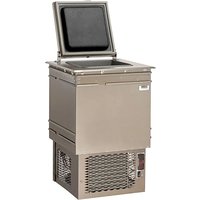
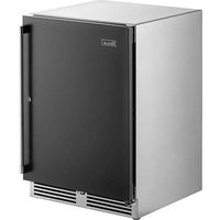
| Product Type | Freezer |
| Brand | Perlick |
| Model | HB24FS |
| Overall Dimensions (Width x Depth x Height) | 23-7/8" x 24" x 32" (606 x 610 x 813 mm) |
| Internal Volume | 4.8 cu ft (136 L) |
| Shipping Weight | 195 lbs (88 kg) |
| Electrical Supply | 115V/60Hz/1Ph, 2.7A |
| Power Cord | 6 ft (1.8 m) with NEMA 5-15P grounded plug |
| Temperature Range | -10°F to 10°F (-23.3°C to -12.2°C) |
| Factory Setpoint | 0°F (-17.8°C) |
| Defrost Type | Automatic hot gas defrost with manual 6-hour defrost option |
| Refrigerant | R600a (Isobutane), 59g |
| Heat Rejection | 700 BTU/hr at 75°F ambient |
| Ventilation | Front-vented |
| Door/Drawer Style | Solid stainless steel or black vinyl/field laminate drawers (lock included) |
| Number of Drawers | 2 |
| Lighting | LED interior light |
| Temperature Control | Digital with programming options |
| Compressor Warranty | 5 years |
| Cabinet Construction Interior | Stainless steel |
| Cabinet Construction Exterior | Stainless steel sides/top, galvanized back/bottom |
| Insulation | Polyurethane-Ecomate, 2" thick |
| Condenser Access | Front, removable grille |
| Plumbing Required | No; self-evaporating condensate pan |
| Compliance | NSF/ANSI Standard 7, cULus listed |
| Accessories Included | Anti-tip brackets; optional casters or legs |
Frequently Asked Questions - HB24FS Perlick
User questions about HB24FS Perlick
0 question about this device. Answer the ones you know or ask your own.
Ask a new question about this device
Download the instructions for your Freezer in PDF format for free! Find your manual HB24FS - Perlick and take your electronic device back in hand. On this page are published all the documents necessary for the use of your device. HB24FS by Perlick.
USER MANUAL HB24FS Perlick
INSTALLATION AND OPERATION INSTRUCTIONS
24" HC SERIES, HB SERIES, & HD SERIES UNDERCOUNTER REFRIGERATION
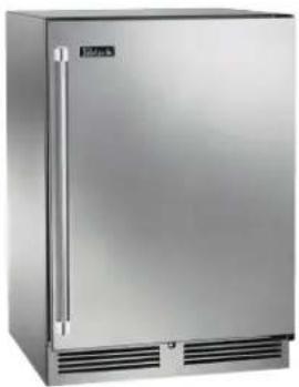
natural_image
Exterior view of a stainless steel multi-door refrigerator with visible doors and ventilation slots (no text or symbols)ADA Refrigerator
HB24RS4
*SS Door Option Shown
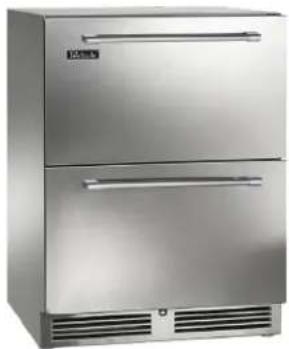
natural_image
Exterior view of a stainless steel double-door refrigerator with two horizontal panels and ventilation slots (no visible text or symbols)Refrigerator
HB24RS4
*SS Drawers Door Option Shown

natural_image
Exterior view of a stainless steel multi-level refrigerator with glass doors and red-labeled items (no visible text or symbols)Wine Reserve
HB24WS4
*SS Glass Door Option Shown


Intertek
For HB24 and HC24 series only

For HD24RS4 and HD24WS4 only

eco-friendly
R600a Refrigerant
The Perlick Corporation verifies this product does not contain a prohibited refrigerant as defined by the California Air Resource Board (CARB), the state of New York, and any other state with HFC prohibition laws. This product does not contain HFC's. The following disclosure statement is provided to comply with the CARB regulation:
This equipment is prohibited from use in California with any refrigerants on the "List Of Prohibited Substances" for that specific end use, in accordance with the California Code of Regulations, title 17, section 95374. This disclosure statement has been reviewed and approved by the Perlick Corporation and the Perlick Corporation attests under penalty of perjury, that these statements are true and accurate.
GENERAL INFORMATION
Introduction
Congratulations on your purchase of a Perlick commercial underbar product. This manual has been prepared to assist you in the installation of your cabinet and to acquaint you with its operation and maintenance.
This manual has been prepared to assist you in the installation of your under counter refrigerator and to acquaint you with its operation and maintenance.
We dedicate considerable time to ensure that our products provide the highest level of customer satisfaction. If service is required, your dealer can provide you with a list of qualified service agents. For your own protection, never return merchandise for credit without our approval.
We thank you for selecting a Perlick product and assure you of our continuing interest in your satisfaction.
Warranty
To register your product, visit our web site at perlick.com. Click on "Commercial", then "Service". Click on the link "Warranty Registration Form". You must complete and submit this form or the installation date will revert back to the ship date.
Please record the purchase date and the dealer's name, address and telephone number below.
Model Number: ____
Serial Number: ____
Purchase Date: ____
Dealer Name & Address
Phone Number
Form No. Z2363
Rev. 01.29.24
Perlick
24" HC SERIES, HB SERIES, & HD SERIES UNDERCOUNTER REFRIGERATION
Operation/Installation Manual
TABLE OF CONTENTS
General Information....1
Safety 2
Cabinet Specifications....3
Preparing the Cabinet for Use Refrigerant....6
Uncrating and Inspection 6
Installation....6
Electrical 6
Use and Operation....7
Repair & Maintenance ....7
Installing Casters or Legs....7
Placing the Cabinet 7
Sealing the Cabinet 8
Preparing the Cabinet 9
Adjusting Full Extension Shelving....9
Operation 10
Checking Product Temperature 10
Digital Temperature Control....10
Programming Button Definitions....11
LED Functions....11
Maintenance 12
Troubleshooting 15
Wiring Diagrams 16
Product/Service/Warranty Information....16
SAFETY
PLEASE READ all instructions completely before attempting to install or operate the unit. Take particular note of the DANGER, WARNING and CAUTION information in the manual. The information is important for the safe and efficient installation, operation and care of your Perlick unit.

Indicates a hazard that WILL result in serious injury or death if precautions are not followed.

Indicates a hazard MAY cause serious injury or death if precautions are not followed.

Indicates a hazard where minor or moderate injury may occur if precautions are not followed.
NOTICE
Indicates that property damage may occur if warnings or instructions are not followed.
IMPORTANT!
Read and understand all information in this manual before attempting the installation. All plumbing and electrical work must be performed by a qualified technician and conform to all applicable state and local codes.

WARNING: California Prop 65 Notice
These products may expose you to chemicals including Chromium, which are known to the state of California to cause cancer and birth defects or other reproductive harm. For more information on whether a product in this list contains these chemicals, please refer to the specific product page at perlick.com. Or to find out more about Prop 65, go to P65Warnings.ca.gov.
Perlick is committed to continuous improvement. Therefore, we reserve the right to change specifications without prior notice
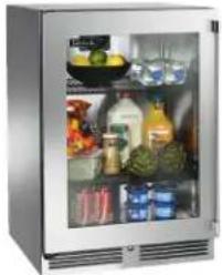
natural_image
Exterior view of a stainless steel refrigerator with open glass doors showing various food items (no visible text or labels)HC24RS4 Refrigerator

natural_image
Exterior view of a stainless steel open refrigerator (no visible text or labels)HC24FS4 Chiller
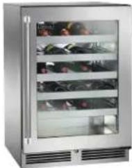
natural_image
Exterior view of a stainless steel multi-level refrigerator with glass doors and side shelves (no visible text or symbols)HC24WS4 Wine Reserve

natural_image
Exterior view of a stainless steel multi-level refrigerator with a vertical chimney (no visible text or symbols)HC24RS4-T1 Beverage Dispenser *Shown with 1 faucet draft arm tapping option
| MODEL NO. |
| HC24FS4 |
| HC24RS4 |
| HC24WS4 |
HC Series Size and Specifications

| MODEL NO. HC24RS4 HC24FS4 HC24WS4 | |||
| CABINET DIMENSIONS | Length Ins. (mm) 23-7/8" (606) 23-7/8" (606) 23-7/8" (606) | ||
| Depth Ins. (mm) 24" (610) 24" (610) 24" (610) | |||
| Height Ins. (mm) 34" (864) 34" (864) 34" (864) | |||
| SHIP WEIGHT LBS. (KG) 185 (83) 195 (88) | 205 (92) | ||
| CAPACITY CU. FT. (L.) [PRODUCT*] | 5.3 (150) [5 cases] | 5.3 (150) [86 glasses] | |
| SHELVING 2 black vinyl-coated full-extension shelf (adjustable) | 2 black vinyl-coated full-extension shelf (adjustable) | 5 black vinyl-coated full-extension wine shelves that hold 8 wine bottles each (750 ml.) (adjustable)Refrigerator & beverage shelving available | |
| TEMPERATURE SETTINGS F°(C) | 34° (1.1) - 42° (5.6)Factory Set Point 36° (2.2°) | -10°(-23.3) - 10°(-12.2)Factory Set Point 0° (-17.8°) | |
| TAPPING | Centered over door only.Tapping option removes shelving. | Not available | |
| CABINET CONSTRUCTION (INT.) | Interior Stainless Steel | ||
| CABINET CONSTRUCTION (EXT.) | Exterior Sides, Exterior Top and Grill Stainless Steel Exterior Back and Exterior Bottom GalvanizedDoor Exterior Customer Choice (see below under 'Customer Options') | ||
| CABINET INSULATION | Polyurethane-Ecomate. Wall Thickness-2" Door, Drawer Thickness-2" (solid stainless steel only) | ||
| DOORS, HINGING & HARDWARE | Number of Doors 1 Opening Style Hinged (Left or Right) Door Style Solid or GlassDoor Swing Clearance 25" (635) Locks Available (factory installed) | ||
| CONDENSING UNIT | Condenser Access Front | ||
| REFRIGERATION | Refrigerant R600a Expansion Device Capillary Tube Type w/Hermetic Compressor Defrost Chiller equipped w/automatic 4-hour hot gas defrost cycle and manual 6-hour defrost with auto restart (HC24FS model only) | ||
| HEAT REJECTION (at 75°F ambient) | 450 btu/hr | 700 btu/hr | |
| PLUMBING | None required. Moisture drains to self evaporating condensate pan | ||
| ELECTRICAL | Electrical Supply 115V/60 Hz/1 Phase Running Load Amps HC24FS4: 2.7A/HC24RS4 & HC24WS4: 1.9 Cord Connection Cord Connected (3-prong 6' NEMA 5-15P) Thermostat Digital Lighting Type LED | ||
| VENTILATION | Front-vented | ||
| CUSTOMER OPTIONS | Door Finishes Black Vinyl/Field Laminate (B), Stainless Steel (S), Glass w/ Black Vinyl/Field Laminate (G), Glass w/ Stainless Steel Frame (T), Stainless Steel Drawers (E), Black Vinyl/Field Laminate Drawers (D) Door Handle Options 24" full length stainless steel, Classic 6" chrome w/black vinyl grip, tab handle (top mount, stainless steel)NOTE: Glass option not available for freezer or beer dispenser | ||
| ADDITIONAL ACCESSORIES | Casters 3.75" (Part No. 66736) Legs 4" -5" (Part No. 66734), 6" -7.25" (Part. No 66735) | ||
*Product capacity based on 12 oz. long neck bottles (Refrigerator), 3" diameter glass size (Freezer) and 750 ml. wine bottles (Wine Reserve)
NOTE: This equipment is intended for the storage and display of non-potentially hazardous bottled or canned products only!
Perlick is committed to continuous improvement. Therefore, we reserve the right to change specifications without prior notice

24" HC SERIES, HB SERIES, & HD SERIES UNDERCOUNTER REFRIGERATION Operation/Installation Manual

natural_image
Exterior view of a stainless steel outdoor refrigerator with ventilation grilles (no visible text or symbols)HB24RS4 Refrigerator

natural_image
Exterior view of a modern stainless steel multi-level refrigerator with glass doors and fruit displays (no visible text or symbols)HB24BS4 Beverage Center
natural_image
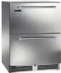
Exterior view of a modern stainless steel double-door refrigerator with two horizontal panels and ventilation grilles (no visible text or symbols)HB24FS4 Freezer Drawers
natural_image
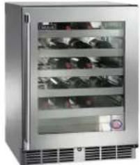
Exterior view of a stainless steel multi-level refrigerator with clear glass doors and ventilation grilles (no visible text or labels)HB24WS4 Wine Reserve
| HB24RS4 Refrigerator | |
| HB24FS4 Freezer | |
| HB24BS4 Beverage | Center |
| HB24WS4 Wine Reserve |
Note: NSF/ANSI Standard 7 Listed for the storage and display of bottled or canned products only.
HB Series Size and Specifications




| MODEL NUMBERS HB24RS4 HB24FS4 HB24BS4 HB24WS4 | |||||
| MODEL DESCRIPTION Refrigerator Freezer Beverage Center Wine Reserve | |||||
| OVERALL DIMENSIONS | Width - in. (mm) 23-7/8 | (606) 23-7/8 (606) 23-7/8 (606) 23-7/8 (606) | |||
| Depth - in. (mm) | 24 (610) | 24 (610) | 24 (610) | 24 (610) | |
| Height - in. (mm) | 32 (813) | 32 (813) | 32 (813) | 32 (813) | |
| OPENING DIMENSIONS | Width - in. (mm) | 24 (610) | 24 (610) | 24 (610) | 24 (610) |
| Depth - in. (mm) | 24 (610) | 24 (610) | 24 (610) | 24 (610) | |
| Height - in. (mm) | 32-1/8 (816) | 32-1/8 (816) | 32-1/8 (816) | 32-1/8 (816) | |
| INTERNAL VOLUME Net. Cu. Ft. (L) | 4.8 (136) | 4.8 (136) | 4.8 (136) | 4.8 (136) | |
| SHIPPING WEIGHT Lbs. (kg.) | 195 (88) | 195 (88) | 195 (88) | 195 (88) | |
| ELECTRICAL SPECIFICATIONS | Electrical Supply | 115 VAC/60 Hz/1 Ph | 115 VAC/60 Hz/1 Ph | 115 VAC/60 Hz/1 Ph | 115 VAC/60 Hz/1 Ph |
| Running Load Amps | 1.9 | 2.7A | 1.9 | 1.9 | |
| Electrical Connection | Cord connected | Cord connected | Cord connected | Cord connected | |
| Cord Plug Type | NEMA 5-15P | NEMA 5-15P | NEMA 5-15P | NEMA 5-15P | |
| Cord Length | 6' | 6' | 6' | 6' | |
| Defrost Initiation | Automatic | Automatic | Automatic | Automatic | |
| Defrost Type | Off cycle | Hot Gas | Off cycle | Off cycle | |
| Thermostat | Digital | Digital | Digital | Digital | |
| Lighting Type | LED | LED | LED | LED | |
| REFRIGERATION SPECIFICATIONS | Refrigerant | R600a (62g) | R600a (59g) | R600a (62g) | R600a (62g) |
| Expansion Device | Capillary Tube | Capillary Tube | Capillary Tube | Capillary Tube | |
| Temperature Settings F (C) | 34° (1.1) - 42° (5.6)Factory Set Point 36°(2.2") | -10° (-23.3) - 10°(-12.2)Factory Set Point 0° (-17.8) | 34° (1.1) - 48° (8.9)Factory Set Point 42°(5.6") | 40° (4.4) - 68° (20)Factory Set Point 55°(12.8") | |
| Heat Rejection | 450BTU/hr | 700BTU/hr | 450BTU/hr | 450BTU/hr | |
| Front Vented | Yes | Yes | Yes | Yes | |
| PLUMBING | None Required None Required None Required None Required | ||||
| AVAILABLE DOOR/DRAWER STYLES | HB24RS4 | HB24FS4 | HB24BS4 | HB24WS4 |
| Solid Black Vinyl/Field Laminate (Lock Optional) | X | X | X | X |
| Solid Stainless Steel (Lock Optional) | X | X | X | X |
| Glass w/Black Vinyl/Field Laminate (Lock Optional) | X | X | X | |
| Glass w/Stainless Steel (Lock Optional) | X | X | X | |
| Drawers Solid Black Vinyl/Field Laminate (Lock INCLUDED) | X | X | ||
| Drawers Stainless Steel (Lock INCLUDED) | X | X |
*Doors/Drawers can be finished with wood overlay panels (by others). Contact Perlick for drawing templates.
Perlick is committed to continuous improvement. Therefore, we reserve the right to change specifications without prior notice
24" HC SERIES, HB SERIES, & HD SERIES UNDERCOUNTER REFRIGERATION
Operation/Installation Manual


natural_image
Exterior view of a stainless steel multi-door refrigerator with ventilation grilles (no text or symbols visible)HD24RS4
Shown with Solid Stainless Steel Door (S)

natural_image
Exterior view of a modern stainless steel refrigerator with open storage compartments filled with colorful food items (no visible text or symbols)HD24RS4
Shown with Glass with Stainless Steel Frame Door (S)

natural_image
Exterior view of a stainless steel multi-level refrigerator with glass doors and side shelves (no visible text or symbols)HD24WS4
Shown with Glass with Stainless Steel Frame Door (S)
| MODELS |
| HD24RS4 |
| HD24WS4 |
HD Series Size and Specifications



| MODEL NO. HD24RS4 HD24WS4 | |||
| MODEL DESCRIPTION Refrigerator Wine Reserve | |||
| CABINET DIMENSIONS | Length Ins. (mm) 23-7/8" (606) | 23-7/8" (606) | |
| Depth Ins. (mm) 18" (457) 18" (457) | |||
| Height Ins. (mm) 32" (813) 32" (813) | |||
| SHIP WEIGHT LBS. (KG) 185 (83) 185 (83) | |||
| CAPACITY CU. FT. (L.) 3.1 (88) 3.1 (88) | |||
| SHELVING | 2 black vinyl-coated full-extension shelves (adjustable) | 4 black vinyl-coated full-extension wine shelves (adjustable). Each wine shelf holds 5 (750 ml) wine bottles. | |
| CABINET CONSTRUCTION (INT.) | Interior Stainless Steel | ||
| CABINET CONSTRUCTION (EXT.) | Exterior Sides, Exterior Top Stainless Steel Exterior Back GalvanizedDoor Exterior Customer Choice (see below under 'Customer Options') | ||
| CABINET INSULATION | Polyurethane-Ecomate. Wall Thickness-2" Door, Drawer Thickness-2" (solid stainless steel only) | ||
| DOORS, HINGING & HARDWARE | Number of Doors 1 Opening Style Hinged (Left or Right) Door Style Solid or GlassDoor Swing Clearance 25" (635) Locks Available (factory installed) | ||
| CONDENSING UNIT | Condenser Access Front | ||
| REFRIGERATION | Refrigerant R600a (62g) Expansion Device Capillary Tube Type w/ Hermetic Compressor | ||
| HEAT REJECTION AT 75°F AMBIENT | 350 BTU/hr | ||
| PLUMBING | None required. Moisture drains to self evaporating condensate pan | ||
| ELECTRICAL | Electrical Supply 115V/60 Hz/1 Phase Running Load Amps 1.9 Cord Connection Cord Connected (3-prong 6' NEMA 5-15P)Thermostat Electro-Mechanical Lighting Type Incandescent | ||
| TEMPERATURE SETTINGS F°(C°) | Temp. Range 34° (1.1°) - 42° (5.6°)Factory Temp. Setting 36°(2.2°) | Temp. Range 40° (4.4°) - 68° (20°)Factory Temp. Setting 55° (12.8°) | |
| CUSTOMER OPTIONS | Door Finishes Black Vinyl/Field Laminate (B), Stainless Steel (S), Glass w/ Black Vinyl/Field Laminate (G), Glass w/ Stainless Steel Frame (T), Black Vinyl/Field Laminate Drawers (D) Door Handle Options 24" full length stainless steel, Classic 6" chrome w/black vinyl grip, tab handle (top mount, stainless steel)NOTE: Glass option not available for freezer | ||
| ADDITIONAL ACCESSORIES | Door Locks (Castors and Legs: Not Applicable) | ||
*Product capacity based on 12 oz. long neck bottles (Refrigerator), 3" diameter glass size (Freezer) and 750 ml. wine bottles (Wine Reserve)
NOTE: This equipment is intended for the storage and display of non-potentially hazardous bottled or canned products only!
Perlick is committed to continuous improvement. Therefore, we reserve the right to change specifications without prior notice
Perlick
24" HC SERIES, HB SERIES, & HD SERIES UNDERCOUNTER REFRIGERATION
Operation/Installation Manual
Refrigerant
DANGER
Take caution when handling, moving and using the product to
avoid damaging the refrigerant tubing or increasing the risk of a leak
WARNING
All service work shall be performed by factory authorized
service personnel and all component parts shall be replaced with like components to minimize the risk of possible ignition due to incorrect parts or improper service.
CAUTION
If service is necessary, repair work must be performed by a Perlick
authorized servicer. Work done by unqualified individuals could potentially be dangerous and will void the warranty.
NOTICE
This product contains blown foam insulation using blowing agent
R-611 (Methyl Formate). The foam in this product does not contain HFC's, CFC's, or HCFC's.
Preparing the Cabinet for Use
UNCRATING AND INSPECTION
Remove all crating material before operating. Carefully inspect cabinet for hidden damage. If damage is discovered, file your claim immediately with the transport company. Perlick is not responsible for damage in transit.
DANGER
Do not use or store flammable liquids (ie; gasoline) or vapors
near the appliance to avoid fire.
INSTALLATION
NOTICE
The unit must NOT be totally enclosed or damage may occur.
Air circulation must not be restricted. The condenser at cabinet front must be provided with a minimum of two inches air space. Be sure to provide access so front cover can be removed to clean the condenser.
NOTICE
If unit has been laid on its back or sides, place unit upright and allow
a minimum of 24 hours before connecting power.
Failure to follow this procedure may damage the compressor and void the warranty.
NOTICE
Use care when handling, moving and using the product to avoid
damaging the refrigerant tubing or increasing the risk of a leak.
All models covered in this user manual are manufactured using refrigerant R600a (Isobutane). R600a is a hydrocarbon. This refrigerant is flammable and is only allowed for use in appliances with fulfill the requirements of UL471, or UL/IEC 60335-1 and UL/IEC 60335-2-89. (To cover potential risk originated from the use of flammable refrigerants). Consequently, R600a is only allowed to be used in refrigerating appliances with are designed for this refrigerant and fulfill the above-mentioned standard.
- R600a is heavier than air. The concentration will always be highest at the floor level.
• The explosion limits are as follows:
o Lower Limit: 1.8% by volume
o Upper Limit: 8.4% by volume
o Ignition Temperature: 460°C
ELECTRICAL
For specifications, see data plate located on the cabinet. Also, see wiring diagram located in this publication.
WARNING
Inspect the electrical cord and plug for damage prior to
energizing the unit to avoid potential electric shock.
WARNING
Use electrical grounding to avoid electrocution or electric shock.
This appliance is equipped with a 3-prong (grounding) polarized plug for your protection against possible shock hazards. Failure to use grounding may result in death, serious injury, or property damage.
WARNING
Never use an extension cord to connect the unit to the electrical
source. Do not use a two-prong adapter or remove the power cord ground prong. Failure to use grounding may result in death, serious injury, or property damage.
NOTICE
Using any voltage other than specified will result in serious
damage to the unit.
USE & OPERATION

Do not use or store flammable liquids (ie; gasoline) or vapors
near the appliance to avoid fire.

To avoid contamination, use food safe containers (not included) for
the storage of craft ice in the cabinet's freezer compartment. This equipment does not include a drain and is intended for use with craft ice and other non-hazardous food stored in food safe containers. Perlick recommends the use of NSF food certified containers.

If service is necessary, repair work should be performed by a Perlick-
authorized service personnel. Work done by unqualified individuals could create dangerous conditions in unit that may result in serious injury or death.
NOTICE
The unit must NOT be totally enclosed or damage may occur.
REPAIR & MAINTENANCE

All service work shall be performed by Perlick-authorized
service personnel. All component parts shall be replaced with like components. Incorrect parts or improper service may result in fire.
INSTALLING CASTERS OR LEGS (OPTIONAL)
Attach bracket assembly to the bottom of the cabinet base using the 14 "-20 Philips head machine screws provided. Attach casters or legs to the mounting bracket with 14 " – 20 Philips head screws provided
NOTICE
To comply with NSF requirements, cabinet must be sealed to floor or
on legs, casters, or rollers.
PLACING THE CABINET
To assure maximum performance, fresh air must be allowed to circulate through the machinery compartment. Do not place anything in front of the cabinet that would obstruct air flow at these grilles. Do not place the unit in an unventilated small room.
NOTICE
Cabinet should be leveled front to back then side to side.
INSTALLING ANTI-TIP BRACKETS
Unit may tip forward if loaded racks/shelves are all pulled out at the same time. To prevent tipping, and to provide stable installation, the unit must be secured in place with the anti-tip brackets supplied with the unit. The anti-tip brackets, when properly installed, should secure the rear legs/glides to the mounting surface and prevent the unit from tipping forward.
Please note:
- Anti-tip brackets are only used for stationary cabinets and should not be installed on cabinets with accessory casters. Caster kits are available for HC and HB model cabinets. Refer to the instructions supplied with the caster kit for proper installation.
- If installing on a concrete floor, concrete fasteners are required and not included with the anti-tip kit.
- Some installation sites may require modifications to provide a secure surface for attaching the brackets.
A set of anti-tip brackets is supplied with the unit. These brackets should be attached to the floor at the rear of the unit. Each bracket must be located to engage the rear glides when the cabinet is pushed back into position. Refer to Figure 1 (shown below) for anti-tip bracket mounting locations.
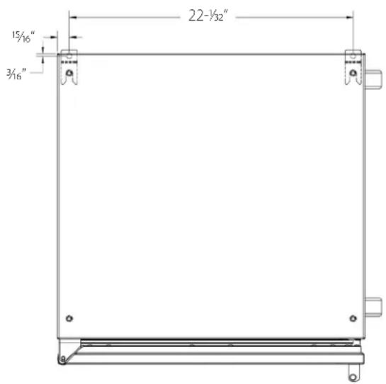
Figure 1.24" Anti-Tip Bracket
WOOD OVERLAY INSTALLATION
Before beginning installation, check all components for proper fit and finish. Handle should be installed to the overlay prior to installing overlay to door (use countersunk flathead fasteners for handle installation.)
CAUTION For best performance and functionality, the overlay panels should be 3/4" thick. The weight of the overlays should not exceed 20 lbs for solid (-2) doors, 10 lbs for glass (-4) doors, or 10 lbs for drawer (-6) models.
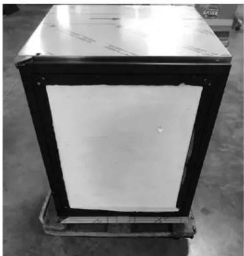
- -2, -4 and -6 models come ready to accept wood overlay as shown below.
natural_image
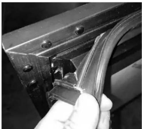
Black-and-white photo of a rectangular industrial box with a black frame and white interior, placed on a wooden pallet (no visible text or symbols)- Remove the gasket carefully starting at the corners and avoid ripping the dart.
natural_image
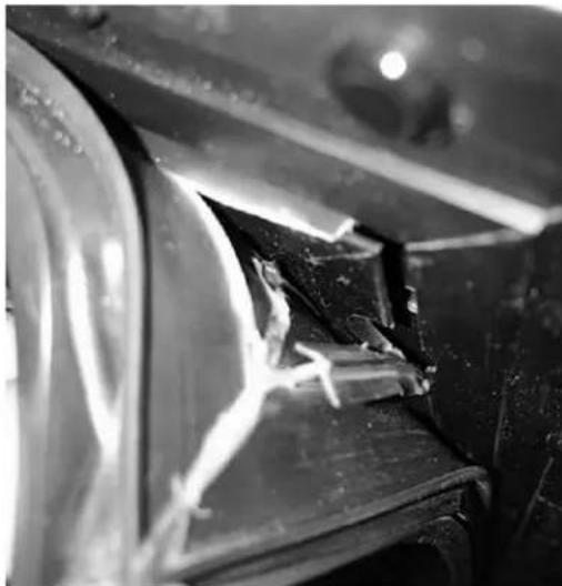
Close-up of a hand holding a metallic bracket with a visible crack, no text or symbols present.- In some cases, the dart on the gasket may rip. If this happens, replace with a new gasket.
natural_image
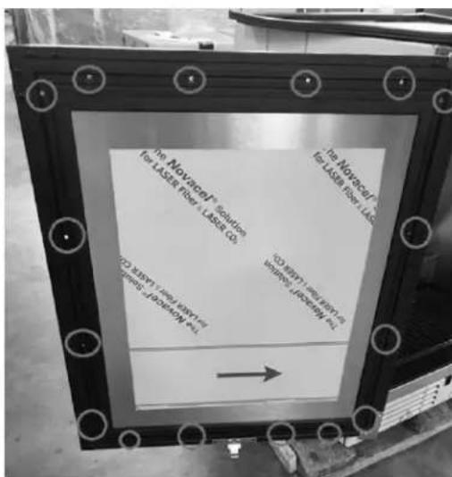
Close-up of a damaged metal structure with visible cracks and debris (no text or symbols)- With the gasket removed, the screw holes needed to hold the overlay panel will be reveal as shown below.
24" HC SERIES, HB SERIES, & HD SERIES UNDERCOUNTER REFRIGERATION
Operation/Installation Manual

- Loosely attached the four corners of the overlay panel with the door frame with #10 x 3/4" wood screws.
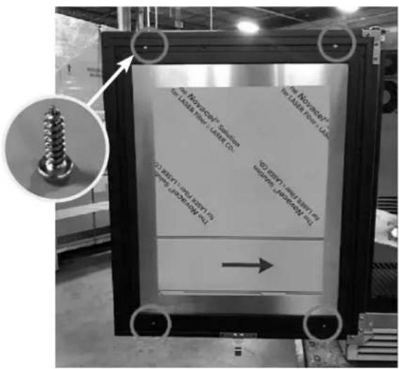
- After alignment is satisfied, fasten down all screws through the screw holes.
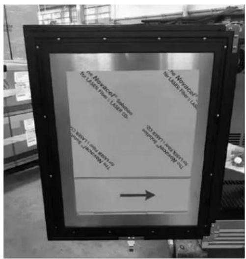
- Make sure the overlay panel is aligned properly with the door.
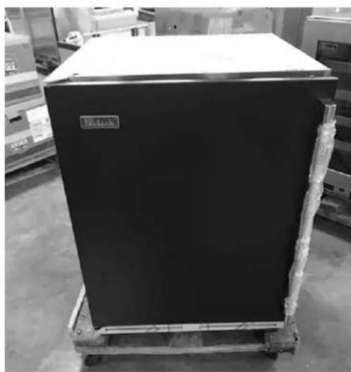
natural_image
Black rectangular industrial box on pallet in warehouse setting (no visible text or symbols)CAUTION Do not overtighten wood overlay attachment screws, as this may damage the factory supplied door frame.
- When re-installing the gasket, make sure the dart is pressed inside the slot on the door frame. Start at the four corners and firmly press your way inwards

natural_image
Close-up of a metal bracket with curved cutouts, no visible text or symbolsPerlick is committed to continuous improvement. Therefore, we reserve the right to change specifications without prior notice
- Verify that the gasket is fully seated onto the door frame when completed.
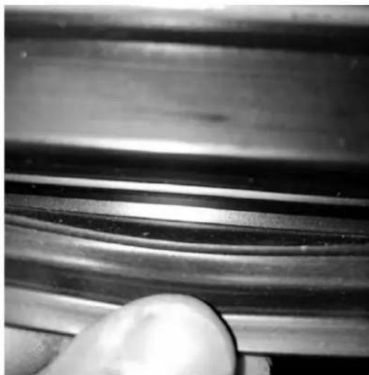
natural_image
Close-up of a metallic mechanical component with layered grooves and a hand holding a white ball (no text or symbols visible)- After installation of the overlay panel is completed, verify that the gasket is completely sealing around the cabinet frame. If installing panels onto drawer models (-6), repeat installation process for second drawer face. Installation is now complete.
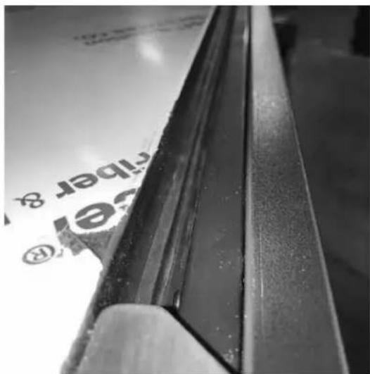
WINE RACK TRIM (OPTIONAL)
All wine reserve racks come with sleek stainless steel fronts. Unfinished solid hardwood fronts are optional and can be removed and replaced with other wood to match your cabinetry. See diagrams below for wine rack face details.
NOTE: The unfinished faces should be finished and sealed. In many cases, stains and/or finishes have odors that may be objectionable in an enclosed area. Do not stain or finish wood faces while installed on unit. To remove the front wood face from the wine shelf, simply pull out the wine shelf and remove the fasteners, finish as desired, and when completely dry, reinstall with fasteners.
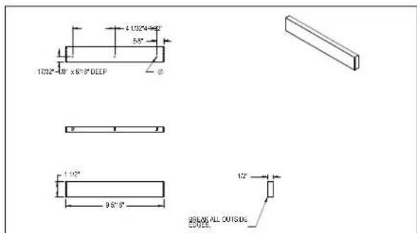
Wine Rack Trim, 15" models
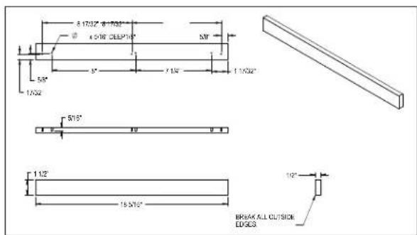
Wine Rack Trim, 24" models
SEALING THE CABINET
NOTICE
Finished flooring should be protected with appropriate
material to avoid damage from moving the unit.
NOTICE
If unit has laid on its back or sides, place unit upright and allow
minimum of 24 hours before connecting power.
NOTICE
To prevent damage to the counter top and unit underneath, do not
place heavy objects on the counter top directly above the unit.
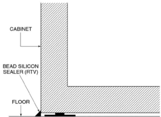
For installation of a cabinet directly to the floor, (without legs or casters), the cabinet must be sealed to the floor to prevent liquid spillage passing under inaccessible portions of the equipment and to maintain the equipment's NSF sanitation certification. The floor surface shall be level and smooth. It is recommended to be sealed to the floor using an NSF certified silicone sealer. (Figure 1).
When sealing the cabinet to the floor, make sure that the louvered front grille plate can still be removed for condenser maintenance and cleaning
Plug the unit into the 15amp grounded outlet located in the installation opening. With power applied to the unit, check that lighting and cooling function operate properly, then turn off power to wall outlet at the circuit breaker.
Check interior door openings inside the unit to ensure the unit is level
PREPARING THE CABINET
NOTICE
TO achieve maximum
performance, interior louver
openings and fan guard openings should never be obstructed.
Refrigerator:
The refrigerator compartments come standard with black vinyl coated adjustable full extension shelves.
Wine Reserve:
The two-door unit comes standard with 4 full extension wine shelves and six full extension black vinyl coated wine shelves. The shelves are removable and adjustable to accommodate oversized (magnum) bottles.
ADJUSTING FULL EXTENSION SHELVING
CAUTION
Shelves should be emptied and free of any product prior to
moving or adjusting.
Pull the shelf out to its furthest position Locate the tabs in the middle of both extenders (see extender tabs below). Press tabs and pull out.
- Reposition each bracket separately. Grasp the middle of the bracket, pull the front end up and out, then forward to remove (See mounting brackets below).
- Place bracket at desired position. Push the rear hook into the rear key slot. Set front of bracket on the wall hook.
- Repeat for other bracket(s).
- Push extenders completely into the unit. Align the shelf grooves with the extenders and slide completely into the unit.

Sliding Shelf Extender Tabs

Sliding Shelf Mounting Brackets
OPERATION
WARNING
Before storing perishables, turn unit on and allow it to operate for a minimum of 24 hours to allow temperatures to stabilize.
NOTICE
When loading items into the unit, do not block internal louvers and fan guard openings or performance will be decreased. For optimal performance, leave a minimum clearance of 1 inch between the loaded product and any internal air openings.
NOTICE
Always ensure that the manual light switch is in the OFF position before closing a solid wood or stainless steel door. If manual light switch is left on for an extended period of time, it may increase the cabinet temperature, and cause the refrigeration system to run harder.
Master Switch
These products come equipped with a master power switch located behind the louvered toe kick. Remove the toe kick to turn power on or off to the unit.
Interior Light
Units are equipped with an interior light that illuminate when the door is opened. All HC48 models come standard with adjustable blue and white LED lighting (except for HC24FS & HB24FS models, which have default white LED light). The cabinet also comes equipped with a manual light switch for displaying the products through a glass door.
Loading Product
Before storing perishables, turn unit on and allow it to operate for a minimum of 24 hours to allow temperatures to stabilize. When loading items into the unit, leave a minimum of 1 inch clearance in front of internal louvers and fan guard openings, blocking airflow will result in decreased performance.
CHECKING PRODUCT TEMPERATURE
-
To accurately check the temperature of product stored in the refrigerated compartment, insert an accurate thermometer into a plastic unbreakable bottle, partially filled with water. Tighten bottle cap securely.
-
Place the bottle in the desired area for 24 hours. Refrain from opening the unit during the testing period. After 24 hours, check the temperature of the water. Adjust the temperature accordingly using the following procedures:
DIGITAL TEMPERATURE CONTROL - REFRIGERATORS, BEVERAGE CENTERS, AND WINE RESERVES
To display the Set point values press the SET' when the 'SET' label is displayed. The Set point value appears on the display. To change the Set point value, press the
and keys within 15 seconds. Press to confirm the modification.
The condenser fan motor turns off and on with compressor. The evaporator fan motor runs continuously.

Digital Temperature Controller
On/Off
Press the ON/OFF button to turn the unit on or off.
Key Combinations:
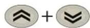
Press the UP and DOWN arrow buttons to lock and unlock the keyboard

Press the SET and DOWN arrow buttons simultaneously to enter programming mode.

Press the SET and UP arrow buttons simultaneously to return to room temperature display.
NOTE: Dependent on the model and configuration, the controllers have been programmed to only allow a temperature adjustment within a specified range. See the chart top right for the specified range allowed for your unit.
SELECTING APPLICATIONS
The procedure for loading one of the default applications is:
- At start-up of the device, keep the SET key pressed: the label "AP1" will appear;
- Browse the various applications (AP1-AP2-AP3-AP4) using the 🔊 and ➕ keys;
- Select the desired application using the SET key ("AP3" in the example) or cancel the procedure by pressing the Ⓞ key; alternatively wait for the timeout;
- If the operation is successful, the display will show "y", if not it will show "n";
- After a few seconds the instrument will return to the main display.
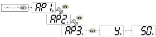
flowchart
graph LR
    A["Power on - SET"] --> B["AP1"]
    B --> C["AP2"]
    C --> D["AP3"]
    D --> E["y"]
    E --> F["50"]
Selecting Applications
| HC/HB/HD 24" Application Temperatures | |||
| Model | AP1 | AP2 | AP3 |
| HB24BSHB24RSHB24WS | Refrigerator(36°F) | Beverage Center(42°F) | Wine Reserve(55°F) |
| HC24RSHC24WS | Refrigerator(36°F) | N/A | Wine Reserve(55°F) |
| HD24RSHD24WS | Refrigerator(36°F) | N/A | Wine Reserve(55°F) |
| HC48RSHC48WS | Refrigerator(36°F) | N/A | Wine Reserve(55°F) |
| HC24 24" C-Series | |
| Model Factory Temp Setpoint | |
| HC24FS4 0°F | |
| HC24RS4 36°F | |
| HC24WS4 55°F | |
| HB24 24" ADA Compliant Series | |
| Model Factory Temp Setpoint | |
| HB24FS4 0°F | |
| HB24RS4 36°F | |
| HB24RS4 42°F | |
| HB24WS4 55°F | |
| HD24 18" Shallow-Depth Series | |
| Model Factory Temp Setpoint | |
| HD24RS4 36°F | |
| HD24WS4 55°F | |
LED Functions
The following table describes LED functions
| LED Mode Function | ||
 | ON Compressor is on | |
 | Flashing | Delay, protection or Blocked start-up |
 | ON Defrost is on | |
 | Flashing | Manual or D.I. activation |
 | ON | Alarm is on |
 | Flashing | Alarm acknowledged |
 | ON | Evaporator is on |
NOTE: An audible alarm will sound on any alarm condition. To silence the active alarm press and release any key on the controller. See the troubleshooting section for description of alarm codes and resolutions.
DIGITAL TEMPERATURE CONTROL - FREEZERS & CHILLERS
On/Off
Press the ON/OFF button to turn the unit on or off.
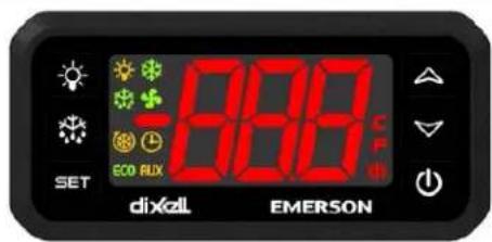
Fig. 2. HC24FS4 & HB24FS4 Controller
Models Built after January 29, 2024
To Set Target Temperature
Press and release the SET button. Display will show the current temperature setpoint.
To Change Setpoint Temperature
-
Press and hold the SET button until the display shows the current setpoint temperature with the "F" flashing.
-
Use the UP and DOWN arrow button to scroll to the desired temperature.
To Start A Manual Defrost (Freezer Models Only)
Press the DEFROST button.

To See Maximum Stored Temperature
Press the UP arrow button to see the maximum stored temperature. To reset the maximum stored temperature, while displayed, press and hold the SET button until 'rst' flashes in the display.
To See Minimum Stored Temperature
Press the DOWN arrow button to see the minimum stored temperature. To reset the minimum stored temperature, while displayed, press and hold the SET button until 'rst' flashes in the display.
Making Selections
Press the SET button to make a selection while in programming mode. When not in programming mode, button will display refrigerator set point.
Defrosting The Unit
All chiller and freezer models models are equipped with an automatic evaporator, automatic hot gas defrost system to allow maintenance free operation of the cooling system.
HC24FS models are also equipped with a six (6) hour manually initiated defrost that users can activate by holding the DEF button for at least three (3) seconds, defrost has initiated when the controller display reads "DEF". After the six (6) hour defrost is complete, the unit will resume to normal operation. All other models employ off cycle defrost systems.
NOTE: Dependent on the model and configuration, the controllers have been programmed to only allow a temperature adjustment within a specified range. See the chart top right for the specified range allowed for your unit.
LED Functions
The following table describes LED functions.
| LED Mode Function | ||
 | ON Compressor is on | |
 | Flashing | Anti-short cycle delay is on |
 | ON Defrost is on | |
 | ON Alarm is on | |
 | Flashing | You are in the process of programming the unit |
Maintenance
Audible alarm will sound if the door is left ajar for longer than one minute. Fully closing the door will clear the alarm condition, prolonged time spent with the door open can damage the equipment.
WARNING
Shut off the electricity to the unit before cleaning the condenser and
other routine maintenance.
CAUTION
NEVER use hydrochloric acid (muriatic acid) on stainless steel. Do not use
abrasive cleansers or cloths on any interior or exterior surfaces or removable parts.
CAUTION
Avoid damaging or crushing the con denser fins or tubing.
STAINLESS STEEL CARE & CLEANING
General
Stainless steel is a “passive” metal because it contains other metals like chromium, nickel and manganese that stabilize the atoms. Chromium provides an invisible passive film that covers the steel surface, acting as a shield against corrosion. As long as the film is intact and not contaminated, the metal is passive and stainless. If the passive film of stainless steel has been broken, equipment can start to corrode and rust.
Three materials or processes can break down stainless steel's passive layer and allow corrosion to occur:
- Mechanical abrasion
- Deposits and water
- Chlorides
Mechanical abrasion refers to items that will scratch a steel surface. Steel pads, wire brushes and scrapers are prime examples.
Water comes out of the faucet in varying degrees of hardness. Hard water may leave spots. When allowed to sit, these deposits will break down the passive chromium layer and rust stainless steel. Other deposits from food preparation must be promptly removed with an appropriate cleaning agent.
Chlorides are found nearly everywhere. They are in water, food and table salt. Household and industrial cleaners are the worst offenders.
Preventing Stainless Steel Rust
Use non-abrasive tools to clean stainless steel products. Soft cloths and plastic scouring pads will not harm the steel's passive layer.
Clean with polish lines. Some stainless steels have visible polishing lines or "grain". When visible lines are present, always scrub in a motion parallel to the lines. When the grain cannot be seen, polish in a consistent straight pattern and not in a circular motion.
Use alkaline, alkaline chlorinated or non-chloride containing cleaners. While many traditional cleaners are loaded with chlorides, the industry is providing an ever-increasing choice of non-chloride cleaners. If you are not sure of chloride content in the cleaner being used, contact your cleaner supplier. If your present cleaner contains chlorides, ask your supplier for an alternative. Avoid cleaners containing quaternary salt; it also can attack stainless steel and cause pitting and rusting. Keep food equipment clean. Use alkaline, alkaline chlorinated or non-chloride cleaners at recommended strength. Clean frequently to avoid build-up of hard, stubborn stains. The single most likely cause of damage is chlorides in the water. Remember, adding heat to cleaners that contain chlorides dramatically increases their effect on stainless steel.
If chlorinated cleaners are used, immediately rinse and wipe equipment and supplies dry. The sooner you wipe standing water, especially when it contains cleaning agents, the better. After wiping equipment down, allow it to air dry. Oxygen helps maintain the stainless steel passive film.
Glass panels may be cleaned using any standard glass cleaner available on the market.
To clean interior and exterior non-metallic surfaces and removable parts, wash with mild solution of soap and lukewarm water with a little baking soda. Rinse and dry thoroughly. Avoid getting water on the lights, controllers, fan motors and unfinished wood wine rack faces.
Cleaning the Condenser

Flammable Refrigerant. Risk of fire or explosion. Do not damage
refrigeration tubes.
The condenser (located behind the front grille cover) should be cleaned every three (3) months. Use a soft bristle brush and vacuum to remove dust and lint.
Recommended Cleaners for Specific Situations
| JOB CLEANING AGENT COMMENTS | ||
| Routine cleaning Soap, ammonia, detergent Apply with sponge or soft cloth | ||
| Fingerprints and smears Areal 20, Lac-O-Nu, Lumin Wash, O-Cedar Cream Polish | Provides barrier film to minimize fingerprints. Can be used on all finishes. Rub the surface with a cloth as directed on the package. | |
| Stubborn stains and discolorations | AllChem Concentrated Cleaner, Samae, Twinkle, Cameo Copper Cleaners, Grade FFF Italian Pumice Whiting, Steel Bright, Lumin Cleaner, Zud Restoro, Sta-Clean, Highlite Cooper's Stainless Steel Cleaner or Revere Stainless Steel Cleaner | Apply with a damp sponge or cloth, then rinse with clear water and wipe dry. |
| Old Dutch, Lighthouse Sunbrite, Wyandotte Bab-O, Gold Dust, Sapollo, Bon Ami or Comet | For these household cleaners, rub with a damp cloth. They may contain chlorine bleaches so rinse thoroughly after use and wipe dry. | |
| Liquid NuSteel or Dubois Temp For these products, rub the surface with a dry cloth using only a small amount of cleanser. Rinse with water and dry. | ||
| Heat tint or heavy discoloration Penny-Brite, Copper Brite, Paste Nu-Steel, Dubois Temp or Tarnite | Rub onto surface with a dry cloth | |
| Bar Keepers Friend, Revere Stainless Steel Cleaner, Allen Polish, Steel Bright Wyandotte Bab-O or Zud | When using these cleaners, apply with a damp sponge or cloth, rinse thoroughly and wipe dry. | |
| Tenacious deposits, rust, discoloration, industrial atmospheric stains | Oakite No. 33 Dilac, Texo NY, Flash-Klenz Caddy Cleaner, Turco Scale 4368 or Permag 57 | Swab and soak with a clean cloth. Let stand for 15 minutes or more according to directions on package, then rinse and wipe dry. |
| Rust discoloration or corrosion caused by cleaning agents containing hydrochloric (muriatic) acid or chlorine bleach | 3M Scotch Pad, type A, grade "fine" Clean off | the surface soil using cleaning methods above. Then rub discolored or corroded areas lightly with a dry pad. |
| Use of property names is intended only to indicate a type of cleaner and does not constitute an endorsement. Omission of any proprietary cleaner does not imply its inadequacy. All products should be used in strict accordance with instructions on the package.NOTE: Do NOT use steel wool or scouring pads to clean stainless steel. | ||
Perlick is committed to continuous improvement. Therefore, we reserve the right to change specifications without prior notice
Troubleshooting

Electrocution hazard! Never attempt to repair or perform
maintenance on the unit until the main electrical power has been disconnected.
If the unit appears to be malfunctioning, read through the OPERATION section first, then check the guide below to identify and resolve the problem.
| PROBLEM RESOLUTION | |
| Light stays on when the door is closed Manual | ON/OFF light switch is turned on. |
| Is the door switch making contact with the plunger? | |
| Noisy during operation | Certain sounds are normal. Soft sounds from the compressor, fan motor and valves will be heard. |
| The refrigerated cabinet isn't running Is there | electrical power to the unit? |
| Is the building circuit breaker or fuse on? | |
| Is the control set properly? | |
| Is the condenser area clean? | |
| The refrigeration compartment is warmer than usual | Is the control set properly? |
| Is the light staying on? | |
| Is the condenser area clean and free of obstruction? | |
| Has the door been open for a long time or more frequently door opening occurred? | |
| Are internal louvers and fan guard openings obstructed? | |
| The refrigerated compartment is cooler than usual | Is the control set properly? |
| Is the door closing and sealing properly? | |
| The refrigerations runs for long periods of time | Is the condenser area clean and free of obstruction? |
| Has the door been open for a long time or more frequently door opening occurred? | |
| Has warm product just been placed in the unit? | |
| On hot days and in warm room temperatures, the system will run longer. | |
| Condensation forms inside the refrigerated compartments | This is normal during high humidity and frequent door openings. |
| Are the doors closing and sealing properly? | |
| Condensation forms on the outside of the unit | During periods of high humidity, some condensation might appear on the outside surface. The condensation will disappear when the humidity drops. Meanwhile, be sure doors are closing and sealing properly. If condensation persists, contact your Perlick Factory Authorized service center. |
| LED Controller display is flashing "E1" - Compartment temperature probe error | Is the main compartment temperature probe firmly plugged into the digital controller? |
| Contact Perlick Factory Authorized service center for replacement probe. | |
| LED Controller display is flashing "E2" - Evaporator temperature probe error | Is the main compartment temperature probe firmly plugged into the digital controller? |
| Contact Perlick Factory Authorized service center for replacement probe. | |
| LED Controller display is flashing "AH1" - High compartment temperature alarm | Refer to problem "The refrigeration compartment is warmer than usual" |
| LED Controller display is flashing "AL1" - Low compartment temperature alarm | Refer to problem "The refrigeration compartment is cooler than usual" |
| LED Controller display is flashing "OPd" - Open door alarm | Has the door been open for longer than 1 minute? |
| Is the door fully closed? | |
| Is the door plunger fully depressing the door switch (right side)? | |
| Is the door switch harness firmly plugged into the digital controller? | |
| Is there continuity across the ends of the door switch harness when the switch is depressed? | |
| Contact Perlick Factory Authorized service center for replacement switch. |
Perlick is committed to continuous improvement. Therefore, we reserve the right to change specifications without prior notice
Wiring Diagram for Models HB24RS4, HB24WS4, HC24RS4, HC24WS4, HD24RS4, HD24WS4

Perlick is committed to continuous improvement. Therefore, we reserve the right to change specifications without prior notice
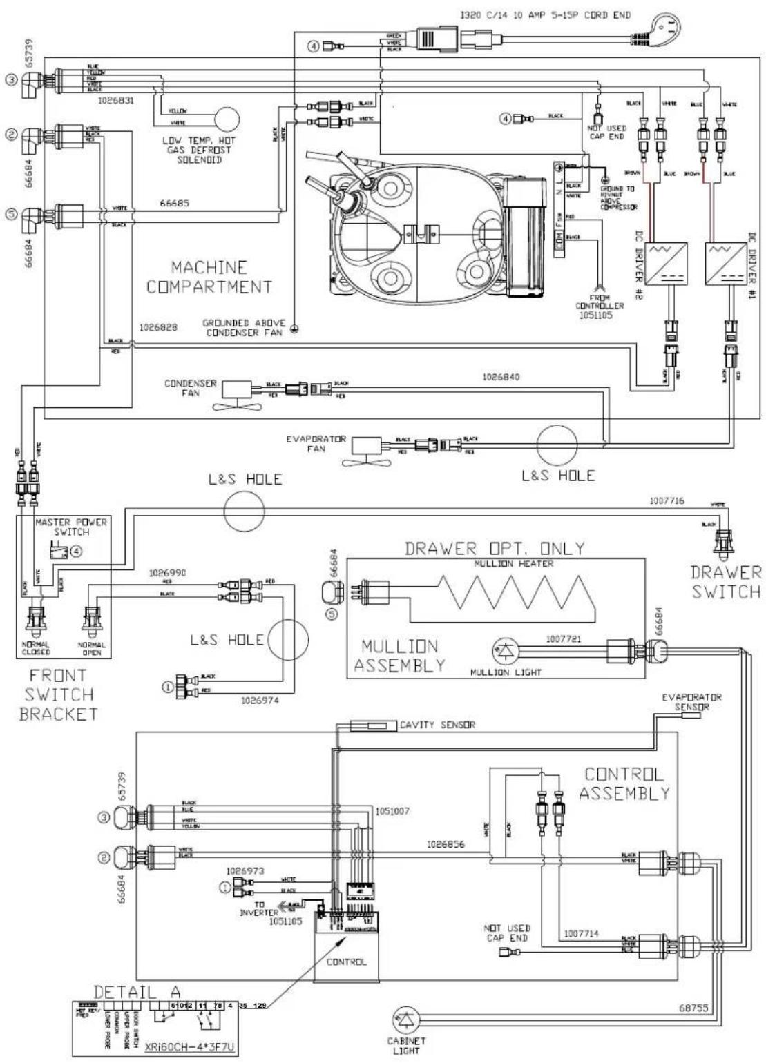
Wiring Diagram for Models HB24FS4, HC24FS4
Perlick is committed to continuous improvement. Therefore, we reserve the right to change specifications without prior notice
Product/Service/Warranty Information
To Obtain Product Information
- Contact your selling dealer.
- Inquire on the web at www.perlick.com.
- Call 800-558-5592 for factory assistance for information, planning, installation or product information.
- Write Perlick Corporation, Customer Service Department, 8300 W. Good Hope Road, Milwaukee, Wisconsin 53223.
• E-mail us at warrantyserv@perlick.com.
To Obtain Product Service, Replacement Parts or Accessories:
Use only genuine Perlick replacement parts and accessories. Genuine Perlick parts and accessories are designed to work correctly with Perlick products and offer superior service life. The use of non-Perlick parts can damage the unit and may void the warranty.
Check the model and serial number of the unit located on the label attached to the inside top of the cabinet.
Call a Perlick Factory Authorized service center. For the location of the nearest Service Center, contact your dealer, or inquire via the web at www.perlick.com, or write to:
Perlick Corporation, Customer Service Department, 8300 W. Good Hope Road, Milwaukee, Wisconsin 53223, call 800-558-5592, or e-mail us at: warrantyserv@perlick.com.
NOTES
NOTES

Form No. Z2363
Rev. 01.29.24

- INSTALLATION AND OPERATION INSTRUCTIONS
- GENERAL INFORMATION
- Introduction
- Warranty
- Perlick
- 24" HC SERIES, HB SERIES, & HD SERIES UNDERCOUNTER REFRIGERATION
- Operation/Installation Manual
- TABLE OF CONTENTS
- SAFETY
- IMPORTANT!
- WARNING: California Prop 65 Notice
- 24" HC SERIES, HB SERIES, & HD SERIES UNDERCOUNTER REFRIGERATION Operation/Installation Manual
- Refrigerant
- DANGER
- WARNING
- CAUTION
- NOTICE
- Preparing the Cabinet for Use
- UNCRATING AND INSPECTION
- INSTALLATION
- ELECTRICAL
- USE & OPERATION
- REPAIR & MAINTENANCE
- INSTALLING CASTERS OR LEGS (OPTIONAL)
- PLACING THE CABINET
- INSTALLING ANTI-TIP BRACKETS
- Please note:
- WOOD OVERLAY INSTALLATION
- CAUTION Do not overtighten wood overlay attachment screws, as this may damage the factory supplied door frame.
- WINE RACK TRIM (OPTIONAL)
- SEALING THE CABINET
- PREPARING THE CABINET
- Refrigerator:
- Wine Reserve:
- ADJUSTING FULL EXTENSION SHELVING
- moving or adjusting.
- OPERATION
- Master Switch
- Interior Light
- Loading Product
- CHECKING PRODUCT TEMPERATURE
- DIGITAL TEMPERATURE CONTROL - REFRIGERATORS, BEVERAGE CENTERS, AND WINE RESERVES
- On/Off
- Key Combinations:
- SELECTING APPLICATIONS
- LED Functions
- DIGITAL TEMPERATURE CONTROL - FREEZERS & CHILLERS
- To Set Target Temperature
- To Change Setpoint Temperature
- To Start A Manual Defrost (Freezer Models Only)
- To See Maximum Stored Temperature
- To See Minimum Stored Temperature
- Making Selections
- Defrosting The Unit
- Maintenance
- STAINLESS STEEL CARE & CLEANING
- General
- Preventing Stainless Steel Rust
- Cleaning the Condenser
- Troubleshooting
- Wiring Diagram for Models HB24RS4, HB24WS4, HC24RS4, HC24WS4, HD24RS4, HD24WS4
- Product/Service/Warranty Information
- To Obtain Product Information
- To Obtain Product Service, Replacement Parts or Accessories:
- NOTES
Brand : Perlick
Model : HB24FS
Category : Freezer