
FR36RT-SS-STK - Freezer Perlick - Free user manual and instructions
Find the device manual for free FR36RT-SS-STK Perlick in PDF.


| Product Type | Glass/Mug Froster Freezer |
| Model Number | FR36RT-SS-STK |
| Exterior Dimensions (L x D x H) | 36 x 24 x 34-1/8 in (914 x 610 x 866 mm) |
| Interior Net Volume | 8.6 cubic ft (242 L) |
| Plate Capacity | 215 plates (9-1/2" diameter x 1/2" thick) |
| Glass Capacity | 142 glasses (3" diameter); optional third shelf increases to 172 |
| Shipping Weight | 245 lbs (111 kg) |
| Cabinet Construction (Interior) | Stainless steel walls and floor |
| Cabinet Construction (Exterior) | Stainless steel front and ends, galvanized back and bottom (SS-STK option) |
| Doors | Sliding style, stainless steel top and bottom pans, die cast handle |
| Plumbing | No drain required; condensate automatically evaporates |
| Insulation | 2-inch foamed-in-place Ecomate® polyurethane |
| Ventilation | Requires 2" clearance from wall on left end or back |
| Temperature Setpoint (Default) | 0 °F (-17.75 °C) |
| Temperature Range | -10 °F to +10 °F (-23.3 °C to -12.2 °C) |
| Power Supply | 120 VAC / 60 Hz / 1 Ph, 3.8 A |
| Power Cord | 6 ft with NEMA 5-15 plug |
| Thermostat | NSF listed electronic digital control |
| Defrost | Automatic every 4 hours (20 min); manual push button (6 hours) |
| Refrigerant | R290 (Propane), 100 g charge |
| Compressor | 1/4 HP, hermetic condensing unit |
| Heat Rejection at 75°F Ambient | 1625 BTU/h |
| Optional Accessories | Flat shelving, divider shelving, roller baskets, legs, casters, bottle rails |
| Safety Features | R290 flammable refrigerant; UL 471 compliant; Prop 65 warning |
| Cleaning | Clean condenser every 30 days; mild detergent for cabinets; no steel wool |
Frequently Asked Questions - FR36RT-SS-STK Perlick
User questions about FR36RT-SS-STK Perlick
0 question about this device. Answer the ones you know or ask your own.
Ask a new question about this device
Download the instructions for your Freezer in PDF format for free! Find your manual FR36RT-SS-STK - Perlick and take your electronic device back in hand. On this page are published all the documents necessary for the use of your device. FR36RT-SS-STK by Perlick.
USER MANUAL FR36RT-SS-STK Perlick
Installation & Operation Manual
Glass/Mug Frosters
FR Series
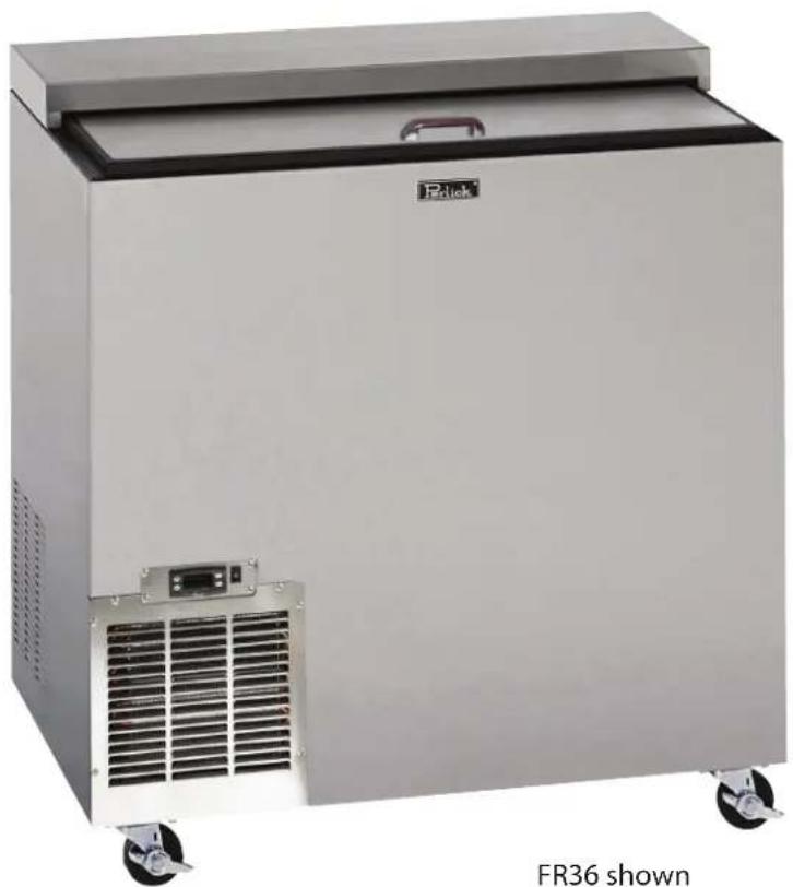
natural_image
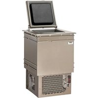
Exterior view of a silver refrigerated industrial machine (no visible text or symbols on the device body)


R290
Refrigerant
The Perlick Corporation verifies this product does not contain a prohibited refrigerant as defined by the California Air Resource Board (CARB), the state of New York, and any other state with HFC prohibition laws. This product does not contain HFC's. The following disclosure statement is provided to comply with the CARB regulation:
This equipment is prohibited from use in California with any refrigerants on the "List Of Prohibited Substances" for that specific end use, in accordance with the California Code of Regulations, title 17, section 95374. This disclosure statement has been reviewed and approved by the Perlick Corporation and the Perlick Corporation attests under penalty of perjury, that these statements are true and accurate.
Form No. Z2633
Rev. 04.20.23

natural_image
Front view of a white industrial refrigerator with cooling fans and ventilation slots (no visible text or symbols)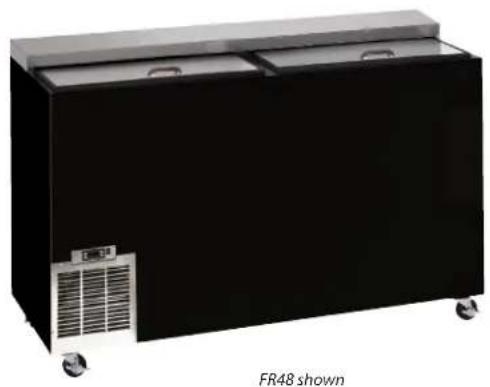
natural_image
Black FR48 refrigerated stainless steel container with cooling fans and wheels (no visible text or symbols)| JOB | |
| AREA | |
| ITEM NO. | |
| MODEL NO. |
| MODEL NUMBERS FR24 FR36 FR48 FR60 | |||||
| EXTERIOR CABINET DIMENSIONS | Length - in. (mm) 24 (610) 36 (914) 48 (1219) 60 (1524) | ||||
| Depth - in. (mm) 24 (610) 24 (610) 24 (610) 24 (610) | |||||
| Height - in. (mm) 34-1/8 (866) 34-1/8 (866) 34-1/8 (866) 34-1/8 (866) | |||||
| INTERNAL NET VOLUME - cubic ft. (liters) 4.2 (118) 8.6 (242) 12.5 (353) 16.3 (462) | |||||
| PLATE CAPACITY * 135 Plates 215 Plates 300 Plates 400 Plates | |||||
| GLASS CAPACITY * | 90 Glasses | 142 Glasses | 214 Glasses | 286 Glasses | |
| W/ OPTIONAL THIRD SHELF | N/A | 172 Glasses | 273 Glasses | 363 Glasses | |
| SHIPPING WEIGHT LBS. (KG.) | 190 (86) | 245 (111) | 300 (136) | 353 (160) | |
| CABINET CONSTRUCTION (INTERIOR) | All models have stainless steel walls and floor. | ||||
| CABINET CONSTRUCTION (EXTERIOR) | Choice of black, stainless steel and all stainless. Black Option: Front and ends are black vinyl coated steel, back and bottom are galvanized. Stainless Steel Option: Front and ends are stainless steel, back and bottom are galvanized. All Stainless Option: Front, ends, back and bottom are all stainless steel. | ||||
| DOORS AND HARDWARE | Sliding style open. Stainless steel top and bottom pans. Die cast handle | ||||
| PLUMBING | No drain required. Condensate evaporates automatically. | ||||
| INSULATION | 2 inch foamed-in-place, environmentally friendly Ecomate® polyurethane insulation. | ||||
| VENTILATION | FR24 model is front vented, all other models require 2" clearance from wall on either left end or back of cabinet for proper air flow. | ||||
| TEMPERATURE SPECIFICATIONS | Default Temperature Setpoint: Standard Temp Models - °F [°C] | 0 [-17.75] | |||
| Adjustable Setpoint Range: Standard Temp Models - °F [°C] | (-) 10 to (+)10 [-23.3 to -12.2] | ||||
| ELECTRICAL SPECIFICATIONS | Supply | 120 VAC/60 Hz/1 Ph | |||
| Running Load Amps | 3.8 | 3.8 | 3.8 | 3.8 | |
| Power Cord | 6-foot length with NEMA 5-15 plug. | ||||
| Thermostat | NSF Listed electronic control. | ||||
| Automatic Defrost | Automatic electric defrost every 4 hours for approximately 20 minutes. | ||||
| Manual Defrost | Push button defrost system, manually initiated at the end of each day. Automatically terminates after six hours. | ||||
| REFRIGERATION SPECIFICATIONS | Condensing Unit | Hermetic condensing unit pulls out for service and cleaning. | |||
| Expansion Device | Capillary Tube | ||||
| Refrigerant | R290 | ||||
| Refrigerant Charge (g) | 80 | 100 | 100 | 115 | |
| Compressor H.P. | 1/4 | 1/4 | 1/4 | 1/4 | |
| Total Heat of Rejection At 75°F ambient (BTU/h) | 1530 | 1625 | 1625 | 1670 | |
| OPTIONAL ACCESSORIES | Flat shelving • Divider shelving • Roller basket shelving Set of 4 Adjustable legs (Multiple sizes available) Set of 4 Casters w/ brakes (Multiple sizes available) • 2; 3; 4; and 5' Bottle Rail (field Installed) | ||||
* Capacity based on use of 3" diameter glass and 9-1/2" diameter X 1/2" thick plate.
This product is evaluated by NSF for the chilling of glassware and plates. This product is not intended for the storage of food products.
Perlick is committed to continuous improvement. Therefore, we reserve the right to change specifications without prior notice.
TABLE OF CONTENTS
Cabinet Specifications....2
Installing
- Refrigerant....4
- Uncrating and Inspection....4
- Plumbing 4
- Electrical....4
-Adjusting Partitions....4 - Installing Casters and Legs 4
- Placing the Cabinet 4
- Sealing to the Floor 5
Temperature Control....5
Defrosting the Unit....5
Cleaning the Cabinet 6
Wiring Diagrams 7/8
Replacement Parts 8/9
Spec Drawings 10
GENERAL INFORMATION SAF
Introduction
This manual has been prepared to assist you in the installation of your Glass Froster and to acquaint you with its operation and maintenance.
We dedicate considerable time to ensure that our products provide the highest level of customer satisfaction. If service is required, call Perlick at 1-800-777-7267 or your dealer who can provide you with a list of qualified service agents. For your own protection, never return merchandise for credit without our approval.
We thank you for selecting a Perlick product and assure you of our continuing interest in your satisfaction.
Warranty
To register your product, visit our web site at www.perlick.com. Click on “Commercial”, then “Service”. Click on the link “Warranty Registration Form”. You must complete and submit this form or the installation date will revert back to the ship date.
Please record the purchase date and the dealer's name, address and telephone number below.
Model Number:
Serial Number:
Purchase Date:
Dealer Name & Address
Phone Number
PLEASE READ all instructions completely before attempting to install or operate the unit. Take particular note of the DANGER, WARNING an CAUTION information in the manual. The information is important for the safe and efficient installation, operation and care of your Perlick unit.
DANGER
Indicates a hazard that WILL result in serious
injury or death if precautions are not followed.
WARNING
Indicates a hazard MAY cause serious injury or
death if precautions are not followed.
CAUTION
Indicates a hazard where minor injury or product
damage may occur if precautions are not followed.
IMPORTANT!
Read and understand all information in this manual before attempting the installation.
All plumbing and electrical work must be performed by a qualified technician and conform to all applicable state and local codes.
! WARNING: California Prop 65 Notice
These products may expose you to chemicals including Chromium, which are known to the state of California to cause cancer and birth defects or other reproductive harm. For more information on whether a product in this list contains these chemicals, please refer to the specific product page at perlick.com. Or to find out more about Prop 65, go to P65Warnings.ca.gov.
Perlick is committed to continuous improvement. Therefore, we reserve the right to change specifications without prior notice.
PREPARING THE CABINET - GLASS FROSTERS
Refrigerant
All models covered in this user manual are manufactured using refrigerant R290 (Propane). R290 is a hydrocarbon. This refrigerant is flammable and is only allowed for use in appliances which fulfill the requirements of UL 471 (To cover potential risk originated from the use of flammable refrigerants). Consequently, R290 is only allowed to be used in refrigerating appliances which are designed for this refrigerant and fulfill the above-mentioned standard.
■ R290 is heavier than air. The concentration will always be highest at floor level.
■ The explosion limits are as follows:
- Lower Limit: 1.7% by vol. (37 g/m3)
- Upper Limit: 9.5% by vol. (177 g/m3)
- Ignition Temperature: 470 °C
DANGER Take caution when handling, moving and using the product to avoid damaging the refrigerant tubing or increasing the risk of a leak.
WARNING All service work shall be performed by factory
authorized service personnel and all component parts shall be replaced with like components to minimize the risk of possible ignition due to incorrect parts or improper service.
⚠️ CAUTION If service is necessary, repair work must be performed by a
Perlick authorized servicer. Work done by unqualified individuals could potentially be dangerous and will void the warranty.
Uncrating and Inspection
Remove all crating material. Carefully inspect cabinet for hidden damage. If damage is discovered, file your claim immediately with the transport company. Perlick is not responsible for damage in transit.
Plumbing
No plumbing connections are required. Condensate from the cooling coil automatically evaporated through a condensate pan located in the condensing unit section.
Electrical
The cabinet must be connected to a separately fused power source (see Electrical Specification Plate affixed to unit) in accordance with National and Local electrical codes.
CAUTION Do not attempt to operate the equipment on any other power source than that listed on the Electrical Specification Plate.
Adjustable Partitions & Shelving
Perlick Glass Frosters may be provided with adjustable partitions and shelving which will accommodate various bottle sizes.
■ When placing glasses in chiller make sure to ensure proper air flow between glasses.
- When loading product into cabinet, care must be taken to avoid blocking airflow into and out of the evaporator. Maintain at least 2" of clearance on evaporator air intake and exhaust for proper operation.
Installing Casters or Legs (optional)
Attach casters or legs to the cabinet bottom in holes provided. Use the supplied 1/4" - 20 hex head self-tapping machine screws. If unit is tipped on its back, wait 24 hours after unit is uprighted to plug the unit in.
Placing the Cabinet
To assure maximum performance, fresh air must be allowed to circulate through the machinery compartment. It is important to allow at least two inches of clearance at the back or left end of the cabinet. Do not place anything in front of the cabinet that would obstruct air flow at these grilles. Do not place the unit in an unventilated small room.
⚠️ CAUTION Removing the factory installed back clearance spacers without providing proper left side grill clearance for compressor air flow will void the warranty.
Perlick is committed to continuous improvement. Therefore, we reserve the right to change specifications without prior notice.
HOW TO OPERATE- GLASS FROSTERS
Cabinet should be leveled.
For installation of a cabinet directly to the floor, (without legs or casters), the cabinet must be sealed to the floor to prevent liquid spillage passing under inaccessible portions of the equipment and to maintain the equipment's NSF sanitation certification. The floor surface shall be level and smooth. It is recommended to be sealed to the floor using an NSF certified silicone sealer. (Figure 1).

Figure 1. Sealing Cabinet to Floor
Temperature Control
A digital temperature control is located on the front face of the Glass Froster, above the condensing unit housing. It is factory set at approximately 0^ F.
Digital Temperature Control
To display the Set point values press the set key when the 'SET' label is displayed. The Set point value appears on the display. To change the Set point value, press the and keys within 15 seconds. Press set to confirm the modification.
The condenser fan motor turns off and on with compressor. The evaporator fan motor runs continuously.

Figure 2: Digital Temperature Controller
Defrosting The System
This system consists of a six-hour, as well as a four hour defrost cycle. The six hour defrost cycle is manually activated and automatically terminated, while the four hour cycle is completely automatic.
The Six Hour Manual Defrost
The six hour manual defrost shuts off the power to the condensing unit, door frame heater, evaporator heater, and the automatic four hour defrost timer, while it supplies power to the evaporator fan. To activate the six hour defrost system, depress (and hold for 3 seconds) the defrost switch located next to the controller above the front grill of the cabinet. When the manual defrost cycle initiates a fan icon will appear on the controller display as well as “def” (figure 3a). When the defrost cycle ends, the cabinet resumes normal operation. To cancel a manual defrost cycle, momentarily turn off the electricity to the machine (unplug unit).

Figure 3a
Automatic Defrost
This automatic defrost ensures that frost will not buildup on the evaporator coil. Every four hours it shuts down the condensing unit, box frame heater, evaporator fan and supplies power to the defrost element clamped to the bottom of the evaporator. When automatic defrost is initiated the controller will display a melting snowflake as well as “def” for the duration of the defrost (figure 3b).

Figure 3b
Perlick is committed to continuous improvement. Therefore, we reserve the right to change specifications without prior notice.
HOW TO OPERATE- GLASS FROSTERS
To manually initiate the automatic defrost cycle press and hold either the up or down arrows. The defrost cycle lasts for approximately 20 minutes followed by 2 minutes of drip time (where the evaporator fan shuts off to allow water to drip off the coil and drain before it can refreeze). (figure 3c).

Figure 3c
When the cycle is complete the unit will resume cooling operation shown on the controller with a snowflake and fan icon, however “def” will remain on the display screen until the next time the set point value is reached (figure 3d). During normal operation it is recommended that the doors are not left open to prevent excessive frost buildup on the coil.

Figure 3d
Cleaning the Condenser
DANGER Flammable Refrigerant. Risk of fire or explosion. Do not damage refrigeration tubes.
■ The condenser (located behind the front grille) should be inspected every 30 days, and cleaned, if necessary. Condenser should be cleaned using a soft bristled brush and vacuum. Failure to keep the condenser clean will cause a loss in condensing unit efficiency, or compressor failure.
Cleaning the Doors
■ Doors should be periodically removed from the cabinet and inspected for a buildup of foreign materials, such as syrups, beer, etc. Buildups on the underside of the doors, along with the cabinet breaker strips on which they ride, will cause them to bind, and therefore, not function as designed. If dirty, these surfaces should be cleaned with a mild detergent and water and then coated with an NSF certified silicone lubricating material.
To remove doors:
■ With door closed, lift it upward by its handle and slide forward until doors clears the cabinet top. Use the reverse procedure to reinstall the doors.
Cleaning the Cabinets
■ Use a damp cloth with a mild detergent and water to clean the inside and outside of the cabinet. Dry thoroughly. Do not allow cleaning agents or large amounts of water to go down the drain. Use an acceptable stainless steel polish to clean all stainless steel surfaces. Never use steel wool or scouring pads to clean stainless steel.
Avoiding Stainless Steel Corrosion
Corrosion can be prevented by following product cautions, cleaning instructions and avoiding use of certain chemicals or objects which will cause stainless steel corrosion.
STAINLESS STEEL ENEMY
■ Steel wool or steel scouring pads
■ Cherry/Orange/Olive juice
■ Chlorine Bleach
■ Sharp Objects
WIRING DIAGRAM - GLASS FROSTERS
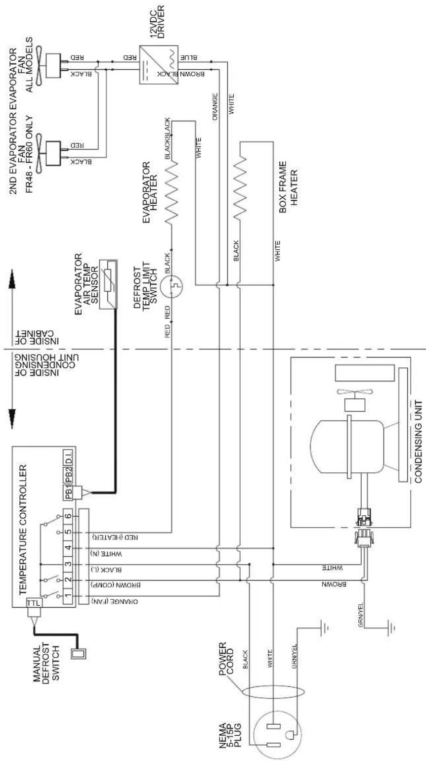
flowchart
graph TD
    A["NEMA 5-15P PLUG"] --> B["POWER CORD"]
    B --> C["ORANGE (FAN)"]
    C --> D["TEMPERATURE CONTROLLER"]
    D --> E["1 2 3 4 5 6 PB1 PB2 D.I."]
    E --> F["ORANGE (COMP)"]
    E --> G["BROWN (L)"]
    E --> H["WHITE (N)"]
    E --> I["RED (HEATER)"]
    J["BOX FRAME HEATER"] --> K["CONDENSING UNIT"]
    L["2ND EVAPORATOR EVAPORATOR FR48 - FR60 ONLY"] --> M["FAN ALL MODELS"]
    N["12VDC DRIVER"] --> O["BROWN BLACK BLUE"]
    P["EVAPORATOR AIR TEMP SENSOR"] --> Q["DEFROST TEMP LIMIT SWITCH"]
    Q --> R["BLACK"]
    Q --> S["BLACKBLACK"]
    T["BOX FRAME HEATER"] --> U["ORANGE"]
    V["CONDENSING UNIT"] --> W["BROWN"]
    X["BOX FRAME HEATER"] --> Y["WHITE"]
    Z["CONDENSING UNIT"] --> AA["WHITE"]
    AB["NAMAL DEFROST SWITCH"] --> AC["ORANGE (FAN)"]
    AD["NAMAL DEFROST SWITCH"] --> AE["ORANGE (COMP)"]
    AF["NAMAL DEFROST SWITCH"] --> AG["WHITE (N)"]
    AH["NAMAL DEFROST SWITCH"] --> AI["RED (HEATER)"]
    AJ["NAMAL DEFROST SWITCH"] --> AK["PB1 PB2 D.I."]
    AL["NAMAL DEFROST SWITCH"] --> AM["PB1 PB2 D.I."]
    AN["INSIDE OF CONDENSING UNIT HOUSING"] --> AO["INSIDE OF CABINET"]
    AP["INDICATOR"] --> AQ["Black"]
    AP --> AR["Red"]
    AP --> AS["Black Black"]
    AP --> AT["Blue"]
    AP --> AU["Black Black"]
    AP --> AV["Black Black"]
    AP --> AW["Black Black"]
    AP --> AX["Black Black"]
    AP --> AY["Black Black"]
Perlick is committed to continuous improvement. Therefore, we reserve the right to change specifications without prior notice.
REPLACEMENT PARTS- GLASS FROSTERS
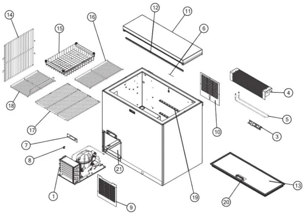
Perlick is committed to continuous improvement. Therefore, we reserve the right to change specifications without prior notice.
REPLACEMENT PARTS- GLASS FROSTERS
| MODEL NOS. FR24 RT - 3 FR36 RT - 3 FR48 RT - 3 FR60 RT - 3 | |||||
| Item Description Part Numbers | |||||
| 1 | Complete condensing unit 1018400 1018400 1018400 1018400 | ||||
| Replacement compressor, R290 C22999CMP11 C22999CMP11 C22999CMP11 C22999CMP11 | |||||
| Condensing unit fan motor assy. 1013047 1013047 1013047 1013047 | |||||
| Condensing unit filter drier C22999DAH01 C22999DAH01 C22999DAH01 | |||||
| Condensing units electrical components | C22999STCP10 | C22999STCP10 | C22999STCP10 | C22999STCP10 | |
| 3 | Evaporator fan | 71386 | 71386 | 71386 | 71386 |
| 4 | Evaporator coil | 64785-1EP | C17511-1EP | C17511-1EP | C17511-2EP |
| 5 | Defrost heater | C25655-1 | 65045-1 | 65045-1 | 61900 |
| 6 | Temperature sensor | 1005668 | 1005668 | 1006584 | 1006584 |
| 7 | Controller Bracket | 1024461-1 | 1024228-2 | 1024428-2 | 1024228-2 |
| 8 | Manual Defrost Switch | 1026317 | 1026317 | 1026317 | 1026317 |
| 9 | Front grille | 1024465-1 | 1024230-1 | 1024230-1 | 1024230-1 |
| 10 | Rear grille/panel | 66498-1 | 65662-3 | 65662-3 | 65662-3 |
| 11 | Top assembly | RT-SL2 | RT-SL2 | RT-SL2 | RT-SL2 |
| 12 | Top wiper gasket | 63671-24 | 63671-36 | 63671-48 | 63671-60 |
| 13 | Door assembly | RD-SL2 | RD-SL2 | RD-SL2 | RD-SL2 |
| 14 | Vertical partition | 65503 | 66441 | 66441 | 66441 |
| 15 | Roller basket | N/A | 66442-1 | 66442-1 | 66442-1 |
| 16 | Wide shelf | N/A | 64811-1 | 64811-1 | 64811-1 |
| 17 | Narrow shelf | 64809-1 | 64809-1 | 64809-1 | 64809-1 |
| Bottom floor rack (wide) | 64814-1 | 64814-1 | 64814-1 | 64814-1 | |
| 18 | Bottom floor rack (narrow) | N/A | N/A | 64815-1 | 64815-1 |
| Shelf with side rail | N/A | 64810-1 | 64810-1 | 64810-1 | |
| 19 | Shelf bracket | 65653-24 | 65653-36 | 65653-48 | 65653-60 |
| 20 | Door handle | 63931 | 63931 | 63931 | 63931 |
| 21 | Evaporator drain pan | 1025311-1 | 1025311-2 | 1025583-1 | 1025583-2 |
ITEMS NOT SHOWN
| Wire harness, main | 1026161 1026161 1026161 1026161 | |||
| Suction line and capillary tube assembly | 1026509 | 1026509 | 1026526 | 1026528 |
| Mullion assembly | N/A | N/A | 66551 | 66551 |
| Refrigerant charge (grams R290) | 80 | 100 | 100 | 115 |
| Defrost temp. limit switch | 57676 | 57676 | 57676 | 57676 |
| Evaporator fan DC driver | 68758 | 68758 | 68758 | 68758 |
| Digital temperature controller | 1026455 1026455 1026455 1026455 | |||
Perlick is committed to continuous improvement. Therefore, we reserve the right to change specifications without prior notice.
SPEC DRAWINGS - GLASS FROSTERS
24" CABINET
![24" [610] 11 5/8" [295] 2 [51] 2" [51] 34 1/8" [866] END VIEW* 24" CABINET](/content/2026/06/1249562/images/d6a7fb9bf21a37b9c3d3e0db10dfe8a898f6a764d759d900e374b98312938ef8.jpg)
![24" [610] 2" [51] 2" [51] 19 1/16" [484] INSIDE FRONT VIEW* 24" CABINET POWER CORD EXIT (BACK OF UNIT)](/content/2026/06/1249562/images/b09f4e57402ed7bd5071bf9e2152ef2b8c4fa37f005ff620288bb8d3bed1cb99.jpg)
36", 48", 60" CABINET
![24" [610] 11 5/8" [295] 2" [51] 34 1/8" [866] END VIEW* 36", 48", 60" CABINET](/content/2026/06/1249562/images/1e651197e29eb30bf19d01020e32cac10308365fcdc28085ed5a7d22d72dc35e.jpg)
![36" [914] 48" [1219] 60" [1524] 2" [51] 2" [51] 17 1/16" [433] HOUSING STEP 27 3/4" [705] INSIDE POWER CORD EXIT (BACK OF UNIT) FRONT VIEW* 36", 48", 60" CABINET](/content/2026/06/1249562/images/eeff1818f363f0d11c6f2461e49d30afb281b7fdb150a11cea07bbab0be10e2c.jpg)
NOTES

Form No. Z2633
Rev. 04.20.23

- Installation & Operation Manual
- This product is evaluated by NSF for the chilling of glassware and plates. This product is not intended for the storage of food products.
- TABLE OF CONTENTS
- GENERAL INFORMATION SAF
- Introduction
- Warranty
- DANGER
- WARNING
- CAUTION
- IMPORTANT!
- ! WARNING: California Prop 65 Notice
- PREPARING THE CABINET - GLASS FROSTERS
- Refrigerant
- Uncrating and Inspection
- Plumbing
- Electrical
- Adjustable Partitions & Shelving
- Installing Casters or Legs (optional)
- Placing the Cabinet
- HOW TO OPERATE- GLASS FROSTERS
- Temperature Control
- Digital Temperature Control
- Defrosting The System
- The Six Hour Manual Defrost
- Automatic Defrost
- Cleaning the Condenser
- Cleaning the Doors
- To remove doors:
- Cleaning the Cabinets
- Avoiding Stainless Steel Corrosion
- STAINLESS STEEL ENEMY
- WIRING DIAGRAM - GLASS FROSTERS
- REPLACEMENT PARTS- GLASS FROSTERS
- SPEC DRAWINGS - GLASS FROSTERS
- NOTES
Brand : Perlick
Model : FR36RT-SS-STK
Category : Freezer