
DVR 4X4 - Separator Smart-AVI - Free user manual and instructions
Find the device manual for free DVR 4X4 Smart-AVI in PDF.


| Product Type | 4x4 Matrix Switch (Separator) |
| Brand | Smart-AVI |
| Model | DVR 4X4 |
| Input Ports | 4 (e.g., HDMI or composite) |
| Output Ports | 4 (independent routing possible) |
| Video Resolution Support | Up to 1080p full HD |
| Dimensions (WxDxH) | 17 x 6 x 1.75 inches (rackmountable, 1U) |
| Weight | Approximately 2 kg |
| Power Supply | 12V DC, 1A (external adapter) |
| Power Consumption | Less than 10W |
| Operation Temperature | 0°C to 50°C |
| Storage Temperature | -20°C to 60°C |
| Humidity | 10% to 90% non-condensing |
| Key Functions | Matrix switching, independent input-to-output routing, IR remote control (optional) |
| Maintenance | Clean with a soft, dry cloth; avoid liquids |
| Safety Precautions | Do not expose to moisture or extreme temperatures; use only provided power adapter |
| Spare Parts Availability | Contact Smart-AVI for replacement power adapters or cables |
| Repairability | No user-serviceable parts; contact authorized service center |
Frequently Asked Questions - DVR 4X4 Smart-AVI
User questions about DVR 4X4 Smart-AVI
0 question about this device. Answer the ones you know or ask your own.
Ask a new question about this device
Download the instructions for your Separator in PDF format for free! Find your manual DVR 4X4 - Smart-AVI and take your electronic device back in hand. On this page are published all the documents necessary for the use of your device. DVR 4X4 by Smart-AVI.
USER MANUAL DVR 4X4 Smart-AVI
USER MANUAL
DVR-4X4 DVI-D 4x4 Router
OVERVIEW
TECHNICAL SPECIFICATIONS 3
WHAT'S IN THE BOX? 4
FRONT AND BACK 4
INSTALLATION 5
DCC LEARNING 6
FRONT PANEL 7
ESTABLISHING AN RS-232 CONNECTION 7-8
RS-232 CONTROL WITH SMART CONTROL PRO 8-10
TROUBLESHOOTING 11
TECHNICAL SUPPORT 11
LIMITED WARRANTY STATEMENT 12
TECHNICAL SPECIFICATIONS
| VIDEO | |
| Format DVI-D Single Line | |
| Input interface (4) DVI-D 29-pin | (Female) |
| Output interface (4) DVI-D 29-pin | (Female) |
| Resolution Up to 1920x1200 @ | 60hz |
| DDC 5 volts p-p (TTL) | |
| Input Equalization Automatic | |
| Input Cable Length Up to 20 ft | |
| Output Cable Length Up to 20 ft | |
| CONTROL | |
| Front Panel Select/Switch between sources | |
| RS-232 DB9 Female - 115200, N, 8, 1, No flow control | |
| OTHER | |
| Power Adapter External 100-240 | VAC/5VDC4A |
| Dimensions 12" W x 2" H x 6.5" | D |
| Weight | 2.3 lbs |
| Operating Temperature | 32 to 104°F (0 to 40°C) |
| Storage Temperature | 4 to 140°F (-20 to 60°C) |
| Humidity | Up to 95% (non-condencing) |
WHAT'S IN THE BOX?
| PART NO. Q-TY DESCRIPTION | ||
| DVR-4X4 1 DVI-D 4x4 Router | ||
| PS5VD4A 1 5 V DC 4 A | ||
| User Manual 1 | ||
FRONT AND BACK
![DVI Router 4X4 Source Smart-AM [1] [2] [3] [4] Input Select Output Select DVR4X4](/content/2026/05/905227/images/fe8418f39a09468ec25c072e6292c8c21b05e9b0d458513c91424fe8774ef270.jpg)
DVR-4X4 Front Panel
![[In 1] [In 2] [Out 2] [Out 1] [In 3] [In 4] [Out 4] [Out 3] RS 232 IR DC-IN 5V smartavi.com Made in USA](/content/2026/05/905227/images/ce6dc06f59aa3a468ab96f88c3e06f33b306c0ed8ea2b4d405c18365d19fc328.jpg)
DVR-4X4 Back Panel
INSTALLATION
- Power off the computers and displays.
- Connect the DVI video cables from the computers to the DVI-D inputs on the rear of the DVR-4X4.
- Connect the DVI displays to the DVI-D outputs on the rear of the DVR-4X4.
- Optionally connect a computer to the RS-232 port on the DVR-4X4 for additional remote control.
- Power on the DVR-4X4.
- Power on the computers and displays. If the monitors don't display correctly see DDC Learning.
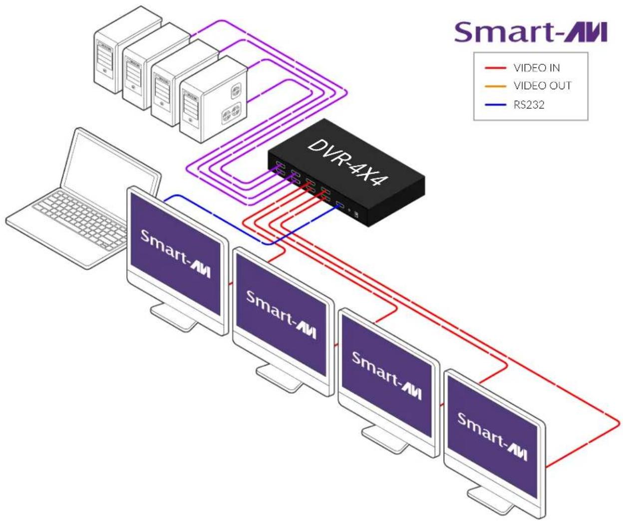
flowchart
graph TD
    A["Server 1"] -->|VIDEO OUT| B["DVR-4X4"]
    C["Server 2"] -->|VIDEO OUT| B
    D["Server 3"] -->|VIDEO OUT| B
    E["Server 4"] -->|VIDEO OUT| B
    F["Laptop"] --> G["Smart-AM1"]
    G --> H["Smart-AM2"]
    H --> I["Smart-AM3"]
    I --> J["Smart-AM4"]
    J --> K["Smart-AM5"]
    K --> L["Smart-AM6"]
    L --> M["Smart-AM7"]
    M --> N["Smart-AM8"]
    N --> O["Smart-AM9"]
    O --> P["Smart-AM10"]
    P --> Q["Video IN"]
    P --> R["Video OUT"]
    P --> S["RS232"]
DDC LEARNING
DDC provides plug-and-play capability to your displays. When you plug a display into your computer, the DDC table in the display tells the computer the optimal resolution to use. In order to preserve this plugand-play capability, we have integrated DDC learning into all of our DVI Solutions.
DDC Learning Menu
Connect 1 monitor only to Output 1.
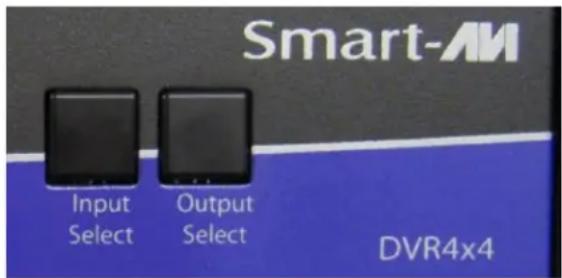
To access the DDC learning feature of the DVR4X4, press and hold both the Input Select and Output Select buttons simultaneously for 3 seconds to enter learning mode. The red LEDs will read LErn.
MENU Options
To cycle through the menu items, press Input Select. To select a menu item, press Output Select and you will exit the DDC menu. To exit the DDC menu, you must select a menu option.
"LE-S" indicates Screen Mode, which learns the type of display connected to the [Out 1] output port. If no screen is detected the display will read Err. This DDC will be used by all the connected computers.
"LE-P" indicates Personal Computer Mode and automatically selects the standard display characteristics of a PC display, which typically works for any PC/Display combination. This DDC is stored in the SmartAVI device and when selected will be used by all the connected computers.
"LE-A" indicates Apple Mode and selects the best display mode to accommodate an Apple Mac. This DDC is stored in the SmartAVI device and when selected will be used by all the connected computers.
![L E r n [1] [2] [3] [4]](/content/2026/05/905227/images/2bb5c2a459906ca9c3abdd895fd219c41a9a96302e3c1760a497f00adcca46f7.jpg)
![L E - 5 [1] [2] [3] [4]](/content/2026/05/905227/images/af79848eedfaad119b352147e1de71dbe2b33a739ffd88887373d9a6a4b43bee.jpg)
![L E - P [1] [2] [3] [4]](/content/2026/05/905227/images/5d0fa6a57e12a0857210c225dd9590f3795041e997e4645d082b9d730f0eb580.jpg)
![L E - A [1] [2] [3] [4]](/content/2026/05/905227/images/2823144f17609c4804e69adbb8193a74a03e69deb921047ab9937a9a6b99f854.jpg)
FRONT PANEL
During normal operation, the unit will display the status of each output with four red LED number. The number indicates the current INPUT or source for each OUTPUT or display indicated by the green LED.
Switching Between Ports
To select an output press Output Select.
The green LEDs will change to indicate the selected output. Then press Input Select and the LED number will change to reflect the selected input. A few seconds later the selected input or source will display on the selected output or display.
![1 2 3 4 [1] [2] [3] [4]](/content/2026/05/905227/images/f528645e34735f5dd55bc4d0fc2984b56d11d1164e9533fdfc7fca6440592ac4.jpg)
ESTABLISHING AN RS-232 CONNECTION
Before you start:
Controlling a SmartAVI device via RS-232 requires an RS-232 card installed on your computer or a USB to RS-232 adapter. Below are instructions on how to create an RS-232 connection between a PC and the SmartAVI device.
Check the device and your PC to determine if you need a male to male or a male to female cable and how long it needs to be. This SmartAVI device uses a straight through cable. You can use a Null Modem Adapter to convert a straight through cable to a crossed cable or a crossed cable to a straight through cable. Examples of crossed and straight thorough cable pin-outs are shown below. The standard maximum length for an RS-232 cable is 50 feet. Call our Smart-AVI Support Engineer if you require more information.
RS-232
DB9 to DB9
Crossed Cable

RS-232
DB9 to DB9
Straight Through Cable

Figure 7-1
Examples of 9 pin RS-232 Straight Through and Crossed Cables
ESTABLISHING AN RS-232 CONNECTION (CONTINUED)
Establish a connection to the Smart-AVI device:
- Connect an RS-232 cable to the RS-232 connector on the PC.
- Connect the other end of the cable to the RS-232 port of the device.
- Use Windows Control Panel / Device Manager to identify the Com port number. See Figure 8-1 below.
- Power on the device.
If you are using a USB to COM port adapter on a Windows PC and need to identify the COM port used, do the following:
- Click on the start button.
- Click on Control Panel.
- Click on Device Manager.
- Click on the arrow next to Ports (COM & LPT).
You should see the name of your adapter and the COM port number in use.

Figure 8-1
RS-232 CONTROL WITH SMART CONTROL PRO
Go to the Smart-AVI website, www.smartavi.com and click Support.
On the Support page click on "HELPFUL LINKS TO SOFTWARE".
On the HELPFUL LINKS page click on SmartControlPro.
SmartControlPro-v5-0-03_Installer.zip should begin to download.
When the download has finished open the .zip file and extract SmartControlPro-v5-0-03_Installer.exe. Execute SmartControlPro-v5-0-03_Installer.exe and follow the prompts to install the Smart Control Pro software on your PC
When executed Smart Control Pro will present you with an opportunity to open a saved configuration. If you later develop a configuration that you frequently use you can save it and load it at this point but for the initial set up click "No".

RS-232 CONTROL WITH SMART CONTROL PRO (CONTINUED)
The "Router Count" drop down selection is for users with more than 1 SmartAVI device.

Figure 9-1
Use the "Router Type" drop down to select your connected SmartAVI device from the list.

Figure 9-2
Select the COM port your computer is connected to your SmartAVI device with from the "Com Port" drop down list. See the section on Establishing an RS-232 connection if you don't know which Com Port to select.

Figure 9-3
Click the "OK" button.
RS-232 CONTROL WITH SMART CONTROL PRO (CONTINUED)
After clicking the "OK" button you will see the main page. Here by selecting the File Tab you can Create and save different configurations and load existing configurations.

Figure 10-1
By clicking on a square to the right of an Input and under an output you can switch that source to that display.
You can also create and store Macros and assign names to your input ports (sources) and output ports (Displays).
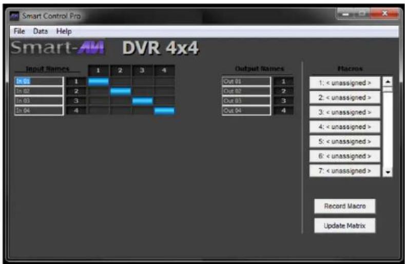
Figure 10-2
TROUBLESHOOTING
No Power
- Make sure that the power adapter is securely connected to the power connector of the unit.
- Check the output voltage of the power supply and make sure that the voltage value is around 5VDC.
- Replace the power supply.
No Video
- Check if all the video cables are connected properly.
- Connect the computer directly to the monitor to verify that your monitor and computer are functioning properly.
- Try replacing the video cable.
- Restart the computers.
TECHNICAL SUPPORT
For product inquiries, warranty questions, or technical questions, please contact info@smartavi.com.
LIMITED WARRANTY STATEMENT
A. Extent of limited warranty
SmartAVI, Inc. warrants to the end-user customers that the SmartAVI product specified above will be free from defects in materials and workmanship for the duration of 1 year, which duration begins on the date of purchase by the customer. Customer is responsible for maintaining proof of date of purchase.
SmartAVI limited warranty covers only those defects which arise as a result of normal use of the product, and do not apply to any:
a. Improper or inadequate maintenance or modifications
b. Operations outside product specifications
c. Mechanical abuse and exposure to severe conditions
If SmartAVI receives, during applicable warranty period, a notice of defect, SmartAVI will at its discretion replace or repair defective product. If SmartAVI is unable to replace or repair defective product covered by the SmartAVI warranty within reasonable period of time, SmartAVI shall refund the cost of the product.
SmartAVI shall have no obligation to repair, replace or refund unit until customer returns defective product to SmartAVI.
Any replacement product could be new or like new, provided that it has functionality at least equal to that of the product being replaced.
SmartAVI limited warranty is valid in any country where the covered product is distributed by SmartAVI.
B. Limitations of warranty
To the extent allowed by local law, neither SmartAVI nor its third party suppliers make any other warranty or condition of any kind whether expressed or implied with respect to the SmartAVI product, and specifically disclaim implied warranties or conditions of merchantability, satisfactory quality, and fitness for a particular purpose.
C. Limitations of liability
To the extent allowed by local law the remedies provided in this warranty statement are the customers sole and exclusive remedies.
To the extent allowed by local law, except for the obligations specifically set forth in this warranty statement, in no event will SmartAVI or its third party suppliers be liable for direct, indirect, special, incidental, or consequential damages whether based on contract, tort or any other legal theory and whether advised of the possibility of such damages.
D. Local law
To the extent that this warranty statement is inconsistent with local law, this warranty statement shall be considered modified to be consistent with such law.
Smart-AM
SMART AUDIO VIDEO INNOVATION
NOTICE
The information contained in this document is subject to change without notice. SmartAVI makes no warranty of any kind with regard to this material, including but not limited to, implied warranties of merchantability and fitness for particular purpose. SmartAVI will not be liable for errors contained herein or for incidental or consequential damages in connection with the furnishing, performance or use of this material. No part of this document may be photocopied, reproduced, or translated into another language without prior written consent from SmartAVI, Inc.
20180109
Tel: (888)-994-7427 • (702)-800-0005
2455 W Cheyenne Ave, Suite 112
North Las Vegas, NV 89032
www.smartavi.com
- USER MANUAL
- OVERVIEW
- TECHNICAL SPECIFICATIONS
- WHAT'S IN THE BOX?
- FRONT AND BACK
- INSTALLATION
- DDC LEARNING
- DDC Learning Menu
- MENU Options
- FRONT PANEL
- Switching Between Ports
- ESTABLISHING AN RS-232 CONNECTION
- Before you start:
- ESTABLISHING AN RS-232 CONNECTION (CONTINUED)
- Establish a connection to the Smart-AVI device:
- RS-232 CONTROL WITH SMART CONTROL PRO
- RS-232 CONTROL WITH SMART CONTROL PRO (CONTINUED)
- TROUBLESHOOTING
- No Power
- No Video
- TECHNICAL SUPPORT
- LIMITED WARRANTY STATEMENT
- Extent of limited warranty
- Limitations of warranty
- Limitations of liability
- Local law
- Smart-AM
- SMART AUDIO VIDEO INNOVATION
- NOTICE
Brand : Smart-AVI
Model : DVR 4X4
Category : Separator