
ControlCenter CC-16 - Régulateur BOSE - Free user manual and instructions
Find the device manual for free ControlCenter CC-16 BOSE in PDF.

| Product Type | Zone Controller for ControlSpace systems |
| Brand | Bose |
| Model | ControlCenter CC-16 |
| Display | 122 x 32 pixel backlit blue LCD |
| Controls | 4 buttons: Select Up/Down, Volume Up/Down |
| IR Receiver | Yes, for IR remote control |
| Network | RS-485, up to 15 units per ESP-88 |
| Max Network Cable Length | 2000 ft (610 m) daisy chain, 1000 ft (305 m) star |
| Power Supply Voltage | 8-18 VDC |
| Power Consumption | 100 mA minimum |
| Address Setting | DIP switches (binary, addresses 1-15) |
| Termination | Built-in resistors, set via DIP switches |
| Mounting | Dual-gang electrical box (North American, Japanese, Australian, European) |
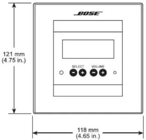
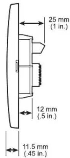
| Dimensions (W x H x D) | 121 mm x 118 mm x 25 mm (4.75 x 4.65 x 1 in) |
| Weight | Approx. 0.3 kg (estimated) |
| Certifications | FCC Class B, ICES-003, CE |
| Cleaning Instructions | Use only a dry cloth |
| Installation | Professional installation recommended; comply with local codes |
| Operating Environment | Indoor, away from moisture and heat sources |
| Warranty | Limited warranty; see BoseProfessional.com/Warranty |
Frequently Asked Questions - ControlCenter CC-16 BOSE
User questions about ControlCenter CC-16 BOSE
0 question about this device. Answer the ones you know or ask your own.
Ask a new question about this device
Download the instructions for your Régulateur in PDF format for free! Find your manual ControlCenter CC-16 - BOSE and take your electronic device back in hand. On this page are published all the documents necessary for the use of your device. ControlCenter CC-16 by BOSE.
USER MANUAL ControlCenter CC-16 BOSE
Safety Instructions
&
Install Guide
Important Safety Instructions
For the intended audience
This guide has been written for professional installers of sound systems.
- Read these instructions – for all components before using this product.
- Keep these instructions – for future reference.
- Heed all warnings – on the product and in the installer's guide.
- Follow all instructions.
- Do not use this apparatus near water or moisture.
- Clean only with a dry cloth - and as directed by Bose Professional.
- Do not block any ventilation openings. Install in accordance with the manufacturer's instructions.
- Do not install near any heat sources, such as radiators, heat registers, stoves or other apparatus (including amplifiers) that produce heat.
- Refer all servicing to qualified service personnel. Servicing is required when the apparatus has been damaged in any way such as: power-supply cord or plug is damaged; liquid has been spilled or objects have fallen into the apparatus; the apparatus has been exposed to rain or moisture, does not operate normally, or has been dropped. Do not attempt to service this product yourself. Opening or removing covers may expose you to dangerous voltages or other hazards. Please call Bose Professional to be referred to an authorized service center near you.
- Do not let objects or liquids enter the product – as they may touch dangerous voltage points or short-out parts that could result in a fire or electric shock.
- See product enclosure for safety related markings.
- Only use attachments/accessories specified by the manufacturer.
Important Safety Instructions
Information about products that generate electrical noise
This equipment has been tested and found to comply with the limits for a Class B digital device, pursuant to Part 15 of the FCC rules. These limits are designed to provide reasonable protection against harmful interference in a residential installation. This equipment generates, uses, and can radiate radio frequency energy and, if not installed and used in accordance with the instructions, may cause harmful interference to radio communications. However, this is no guarantee that interference will not occur in a particular installation. If this equipment does cause harmful interference to radio or television reception, which can be determined by turning the equipment off and on, you are encouraged to try to correct the interference by one or more of the following measures:
- Reorient or relocate the receiving antenna.
- Increase the separation between the equipment and receiver.
- Connect the equipment to an outlet on a different circuit than the one to which the receiver is connected.
- Consult the dealer or an experienced radio/TV technician for help.
This product complies with the Canadian ICES-003 Class B specifications.
The information furnished in this install guide does not include all of the details of design, production, or variations of the equipment. Nor does it cover every possible situation which may arise during installation, operation, or maintenance. If you need assistance beyond the scope of this user's guide, please contact our Customer Service department.
Important Safety Instructions
Caution
Check local regulations before installing the ControlSpace CC-16 zone controller. The building code may require professional installation by a skilled technician or licensed contractor. Regional electrical codes may require similar qualifications for wiring the system. This product must be used with a Class 2 power supply.
Please read this install guide
The CC-16 zone controller is engineered to provide customized on-site controls for ControlSpace sound systems. Please read this guide to help you install and use your controller correctly.
Regulatory information
An example of this equipment has been tested and found to comply with the following International Standards for Electromagnetic Compatibility:
Radiated Emissions (EU) EN55103-1
Immunity (EU) EN55103-2
Radiated Emissions (USA): FCC part 15 Class B
This Class B device meets all requirements of the Canadian Interference-Causing Equipment Regulations.
Introduction
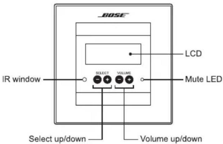
The Bose Professional ControlSpace CC-16 zone controller is an elegant wall-mounted device designed to provide end-user control of ControlSpace systems. Custom programming allows the CC-16 to control a variety of the system elements, from switching audio sources to selecting “scenes” or system configurations. The CC-16 features a bitmap LCD and four buttons for displaying and controlling the system settings.
The CC-16 connects to the ControlSpace Engineered Sound Processor (ESP-88) at the RS-485 port. Up to fifteen CC-16 units can be used per each ESP-88 to provide localized control of the system. The maximum distance from ESP-88 to CC-16 is 2000 feet. As a networked device, remote reprogramming is possible at any time.
Features and functions
• 122 x 32 pixel backlit blue LCD
• LCD displays volume level and source/scene/preset setting
- Select up/down buttons for selecting sources or scenes
• Volume up/down buttons for controlling one or more gain controls
• IR receiver (for IR remote controls)
• RS-485 network supports up to fifteen CC-16 units per ESP-88
• DIP-switch for specifying net-work address and termination
• Universal mounting bracket
Introduction
Quick start
- Run power and network (2-wire) cables from the ESP-88 to the CC-16 mounting location and install a mounting box.
- Set the DIP switches to define the unit address and termination (see silkscreen on back of CC-16).
- Connect the power and network wires to the CC-16's terminal block and insert unit into the mounting box.
- At the ESP-88, connect the network wire to the RS-485 port and connect the power cable to a power source.
- Run the ControlSpaceDesigner software to configure and test. The CC-16 must be connected to an ESP and configured with the ControlSpace Designer software before it can be used. Please refer to the Designer User's Guide for complete details on configuring and programming the CC-16 in a ControlSpace system.
CAUTION: The building code may require professional installation by a skilled technician or licensed contractor.
Installation
Cabling
The CC-16 zone controller requires power and network cables. In some cases, these can be supplied over the same multi-conductor cable. When multiple CC-16s are used, run the network (and optionally the power cable) from the ESP-88 to each zone controller in a daisy chain. You can also run multiple home runs from the ESP-88 to each CC-16 in a star configuration.
Note: The ESP-88 does not supply power to the CC-16 zone controller. A separate power supply (not included) must be provided. Refer to Power Supply on page 12 for more information about the required power supply.
The CC-16 can be wired using commonly available twisted-pair wire such as 24 AWG unshielded CAT-5. Only one pair of wires is needed for the network connection. For a daisy chain wired system, the maximum cable length is 2000 feet (610 meters). For a star topology, the maximum length is 1000 feet (305 meters).
When supplying power over the same cable as the network pair, the limiting factor will be the resistive loss in the wire. Smaller-gauge wire, will have higher resistance and cause a larger voltage drop at the CC-16. The CC-16 requires a minimum of 8VDC. 24 AWG wire has resistance of about 27 ohms per 1000 feet (305 meters), while 18 AWG wire has a resistance of about 7 ohms per 1000 feet (305 meters).
The maximum distance can be calculated as follows:
$$ d = \left(\left(V _ {\text { SUPPLY }} - 8 V\right) / \left(\text { Number of CC - 16s } * 1 0 0 \mathrm{mA}\right)\right) / R _ {\text { WIRE }}) ^ {*} 1 0 0 0 \text { feet }) $$
For example, if V_SUPPLY is 12V, the number of CC-16s = 2 and R_WIRE = 27 (24 AWG), then:
$$ \begin{array}{l} \mathrm {d = ((12V - 8V) / (2100mA)) / 27)1000 feet) = (4/.2 / 27*1000 feet) = 750 feet(225} \ \text { meters) } \end{array} $$
Maximum cable distances
| Wire Gauge/Power Supply Voltage | Number of CC-16s | |||
| 1 2 4 15 | ||||
| 24 AWG 18V 2000 | ft (610 m) | 1852 ft (564 m) | 926 ft (282 m) | 247 ft (75 m) |
| 24 AWG 12V 1481 ft | (451 m) | 741 ft (226 m) | 370 ft (113 m) | 99 ft (30 m) |
| 24 AWG 9V 370 ft | (113 m) | 185 ft (56 m) | 93 ft (28 m) | 25 ft (7 m) |
| 18 AWG 18V | 2000 ft (610 m) | 2000 ft (610 m) | 2000 ft (610 m) | 1010 ft (308 m) |
| 18 AWG 12V | 2000 ft (610 m) | 2000 ft (610 m) | 1515 ft (461 m) | 404 ft (123 m) |
| 18 AWG 9V | 1515 ft (461 m) | 758 ft (231 m) | 379 ft (115 m) | 101 ft (31 m) |
Installing the mounting box
Install a dual-gang electrical box for each CC-16. Install the wall box so that it is flush or just below the surface of the finished wall. The unit is designed to fit in North American, Japanese, Australian and some European dual-gang electrical boxes. Mount the
European and Australian double-gang boxes horizontally and the North American and
Japanese boxes vertically as shown below.
Select a place that is convenient for the people who will be controlling the system. We suggest mounting the unit at eye-level for optimal LCD viewing angle.
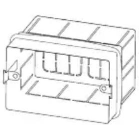
natural_image
Technical line drawing of a rectangular electronic component with internal slots and mounting holes (no text or symbols)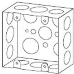
natural_image
Isometric line drawing of a rectangular box with circular holes and mounting holes (no text or symbols)CAUTION: Do not install the CC-16 in a box that has AC power (mains).
CAUTION: Do not place the power or network cables in the same conduit with the mains wire, unless you are sure that special regulatory insulation requirements are met. Consult your local electrical regulatory agency for further information.
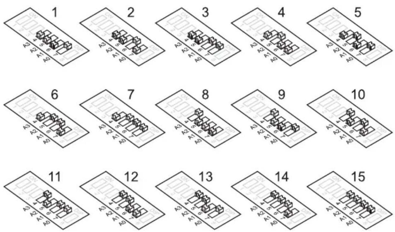
DIP Switch Settings
The CC-16 zone controller has an 8-position DIP switch located on the back of the unit. The DIP switches control addressing and termination settings.
DIP switch addresses
Up to fifteen CC-16s can be connected to an ESP-88 and each must have a unique address. Use the DIP switches numbered 4, 5, 6 and 7 on the back of the unit to set the address – 1 through 15. The addresses are in binary format. Refer to the illustration below to locate binary addresses and the corresponding switch positions.
DIP Switch Settings
Termination
The CC-16 zone controller uses a 2-wire RS-485 network to communicate with the ESP-88 sound processor. For optimum performance, the RS-485 network must be “terminated.” The EC-16 includes built-in termination resistors which make it easy to terminate the network. Termination is accomplished by setting DIP switches 1 and 2 to the ON position.
- In most cases, only one CC-16 zone controller – the last unit in the daisy chain network (furthest away from the ESP-88) should have the termination set to ON.
- In a star topology, with the ESP-88 in the middle of two or more long runs, two units (the two furthest from the ESP-88) should have the termination set to ON.
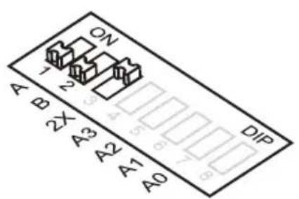
Termination OFF
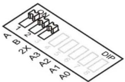
Termination ON
Note: Switch 3 (2X) should always be in the ON position.
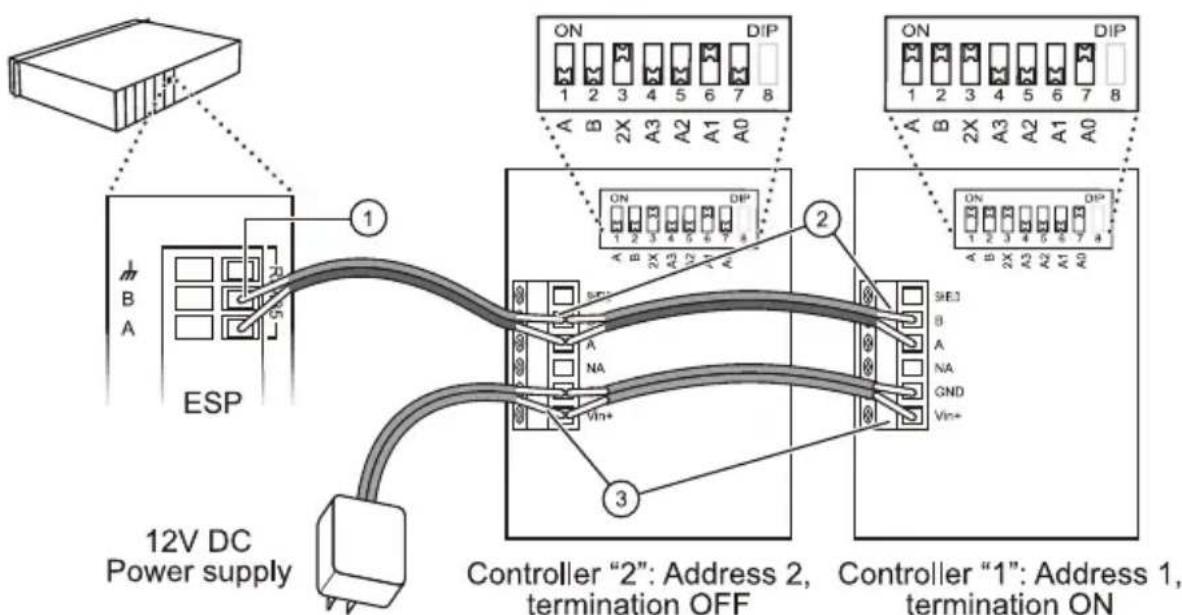
Wiring
Connecting the wires
The CC-16 zone controller uses a standard 6-wire Eurostyle terminal block for power and network connections.
- Connect the network cable to the RS-485 A/B pins on the ESP-88. Note which wire is connected to A and B.
- Connect the network cable to the CC-16 terminal blocks. Ensure the wire connected to "A" on the ESP-88 is the same one connected to "A" on the controllers and that the "B-wire" is connected to "B" on the controllers. Connect Shield to the RS-485 cable shield if necessary.
- Connect the power supply to the Ground and Vin+ terminals on the controllers.
Wiring Example
flowchart
graph TD
    A["ESP"] -->|1| B["Controller "2": Address 2, termination OFF"]
    A -->|3| C["Controller "1": Address 1, termination ON"]
    D["12V DC Power supply"] -->|B A| E["Control Block 1"]
    D -->|A B| F["Control Block 2"]
    D -->|A C A B A3 A2 A1 A0| G["Control Block 3"]
    H["ON"] --> I["1 2 3 4 5 6 7 8"]
    J["DIP"] --> K["1 2 3 4 5 6 7 8"]
    L["ON"] --> M["1 2 3 4 5 6 7 8"]
    N["ON"] --> O["1 2 3 4 5 6 7 8"]
    P["ON"] --> Q["1 2 3 4 5 6 7 8"]
    R["ON"] --> S["1 2 3 4 5 6 7 8"]
    T["ON"] --> U["1 2 3 4 5 6 7 8"]
Wiring
Power supply
The CC-16 zone controller requires a minimum of 100mA at 8VDC. For convenience and consistency, we recommend you place the power supply in an equipment area adjacent to the network connection.
Power can be supplied over the network cable, from a power supply local to the unit, or from a remotely-located power supply with a separate cable run. The required cable AWG is dependent on the length of the run—the longer the run, the higher the voltage drop in the cable and the lower the required cable AWG.
Use the ControlSpace™ accessory power supply or other suitable supply. Individual country requirements are:
- North America: Power supplies used in North America must be NRTL listed and/or CSA certified Class 2 supplies, as appropriate.
- Europe: Power supplies must be CE Marked and be certified by an accredited third party Regulatory Agency.
- Japan: Power supplies used in Japan must be in compliance with DENAN Law and be marked with the PSE diamond.
CAUTION: Never use more than one power supply on the same wire as this could cause slight differences in voltage that could damage the power supplies and/or the CC-16.
Mounting
Mounting the CC-16 zone controller
Warning: The CC-16 must be installed in a National Electric Code (NEC) approved, enclosed electrical wall box.
After setting the DIP switches and connecting the wires, mount the CC-16 zone controller in the electrical box. Two sets of screws are provided. Use the screws that are appropriate for your wall-box – the #6 for North American boxes, and the M4 for Japanese, European and Australian boxes.
CAUTION: Do not overtighten the screws. Overtightening may cause the frame to break.
Mounting the CC-16 Zone Controller in a North American 2-gang wall box
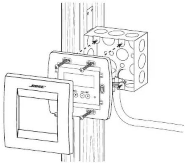
natural_image
Technical line drawing of a wall-mounted electrical enclosure with mounting holes and wiring (no text or symbols)After screwing the frame into the wall box, remove the protective clear film and snap on the cover. The cover can be removed later using a small flathead screwdriver in the slots on the sides.
Troubleshooting
| No power • Ensure that the power supply is wired correctly and plugged inTry disconnecting other CC-16s if sharing a supplyVerify that the supply is DC and provides a minimum 100mA at 8V | |
| Screen is blank • Press a button to see if backlight comes on (the backlight turns off after a period of inactivity) | |
| No response when Volume or Select up/ down buttons are pressed | Check to see if the device is connected to an ESP-88Check the polarity of the wiring to the ESP-88 (A->A, B->B)Check the DIP switch settings (2X should be ON )If this is the end of a long run, check that the termination DIP switches are set to ONCheck that the Select and/or Volume parameters have been programmed using the Designer software. Refer to the ControlSpace ^TM Designer Software user's guide for more informationCheck that the controls have been linked (in the Designer software) to signal processing blocks in the ESP-88Ensure that the CC-16 address (set with DIP switches) matches the address of the device you programmed in Designer |
| Power on, but no sound | Check that the system is not mutedCheck that other components (sources and amps) are not muted and are wired correctly |
| Cannot “find” the device in Designer | Verify that an ESP-88 has been added to your designVerify that the ESP-88 “finds” the CC-16. (Look for the CC- 16 in the Properties window and be sure it corresponds with the address you set on the CC-16.) |
Specifications
Input voltage
8 - 18VDC, 100mA
Max network cable length
2000 feet (609m)
Number of CC-16 zone controllers per ESP-88 Sound Processor
15
Dimensions

This product conforms to all applicable EU directive requirements. The complete Declaration of Conformity can be found at www.Bose.com/compliance.
This product conforms to all applicable Electromagnetic Compatibility Regulations 2016 and all other applicable UK regulations. The complete declaration of conformity can be found at:
www.Bose.com/compliance
China Importer: Bose Electronics (Shanghai) Company Limited, Level 6, Tower D, No. 2337 Gudai Rd. Minhang District, Shanghai 201100
UK Importer: Bose Limited Bose House, Quayside Chatham Maritime, Chatham, Kent, ME4 4QZ, United Kingdom
EU Importer: Bose Products B.V., Gorslaan 60, 1441 RG Purmerend, The Netherlands
Mexico Importer: Bose de México, S. de R.L. de C.V., Paseo de las Palmas 405-204, Lomas de Chapultepec, 11000 México, D.F. For importer & service information: +5255 (5202) 3545
Taiwan Importer: Bose Taiwan Branch, 9F-A1, No. 10, Section 3, Minsheng East Road, Taipei City 104, Taiwan. Phone Number: +886-2-2514 7676
Bose is a trademark of Bose Corporation.
ControlSpace is a trademark of Transom Post OpCo LLC.
Bose Corporation, Framingham, MA 01701, U.S.A. 1-877-230-5639
©2023 Transom Post OpCo LLC. No part of this work may be reproduced, modified, distributed or otherwise used without prior written permission.
Limited Warranty
Your product is covered by a limited warranty. Visit BoseProfessional.com/Warranty for warranty details.

PROFESSIONAL

285042-0030
©2023 Transom Post OpCo LLC. All rights reserved.
Framingham, MA 01701 USA
BoseProfessional.com
AM285042 Rev. 04
August 2023