SF2111H-DR - Security Camera AVer - Free user manual and instructions
Find the device manual for free SF2111H-DR AVer in PDF.


| Product Type | Security Camera (Vandal Dome) |
| Model | SF2111H-DR |
| Image Sensor | 1/2.7" CMOS, 2 Megapixel |
| Lens | Vari-focal 3~9 mm |
| Video Resolution | Up to 1920x1080 (Full HD 1080p) |
| Video Compression | H.264, MJPEG, MPEG-4 |
| Frame Rate | 30 fps at 1080p |
| IR Distance | 15 m |
| IR LEDs | 18 built-in |
| IR Cut Filter | Mechanical |
| Audio | 2-way (mono) |
| Network Interface | 10/100 Base-T Ethernet, PoE |
| Power Supply | DC 12V (adapter optional) |
| Power over Ethernet | Yes (802.3at recommended) |
| Dimensions (W x L x D) | 126 x 126 x 100 mm |
| Weight | Approx. 0.5 kg |
| Housing | Vandal dome, IP66 |
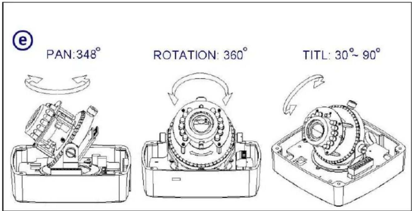
| Pan / Tilt / Rotation | 348° / 30°~90° / 360° |
| Storage | microSD/SDHC slot (max 32 GB) |
| I/O Ports | 1 sensor in, 1 relay out, video out |
| Recording Software | Free bundled NXU Lite |
| Mobile Support | iOS 4.3+, Android 1.6+ |
| Web Browser | Internet Explorer 6.0+ (32-bit) |
| Motion Detection | 3 adjustable areas |
| Privacy Mask | 3 configurable areas |
Frequently Asked Questions - SF2111H-DR AVer
User questions about SF2111H-DR AVer
0 question about this device. Answer the ones you know or ask your own.
Ask a new question about this device
Download the instructions for your Security Camera in PDF format for free! Find your manual SF2111H-DR - AVer and take your electronic device back in hand. On this page are published all the documents necessary for the use of your device. SF2111H-DR by AVer.
USER MANUAL SF2111H-DR AVer
natural_image
Front view of a white AVer surveillance camera with visible lens and three sensors (no text or symbols on the device itself)AVer SF2111H-DVR
User Manual
Table of Contents
PREFACE ....1
PRODUCT SPECIFICATIONS....1
PACKAGE CONTENTS......4
PRODUCT INSTALLATION....5
MONITOR SETTING ....5
HARDWARE INSTALLATION AND I/O PIN ASSIGNMENT 6
POWER OVER ETHERNET (PoE)....10
IP ASSIGNMENT....11
FINDING IP CAMERA BY USING "NXU LITE RECORDING SOFTWARE"......11
FINDING IP CAMERA BY USING "IP INSTALLER" 14
USING DHCP SERVER/ROUTER NETWORK....16
USING NON-DHCP SERVER/ROUTER NETWORK....17
INSTALL ACTIVEX CONTROL....20
USING THE IP CAMERA BROWSER INTERFACE 22
PREVIEW 22
SYSTEM > GENERAL 24
SYSTEM > GENERAL > MAINTENANCE....24
To Upgrade the IP Camera Firmware 25
SYSTEM > GENERAL > DATE & TIME....26
SYSTEM > USER MANAGEMENT ....27
SYSTEM > USER MANAGEMENT > ACCOUNT....27
SYSTEM > NETWORK SETTING > SETTING....29
SYSTEM > NETWORK SETTING > SEVER 30
SYSTEM > NETWORK SETTING > DDNS 31
SYSTEM > NETWORK SETTING > OTHER 1 ....33
SYSTEM > NETWORK SETTING > OTHER 2 ....35
TROUBLESHOOTING....66
APPENDIX....67
COPYRIGHT 68
NOTICE......68
WARNING....68
GOVERNING LAW AND YOUR RIGHTS .... 70
Preface
The SF2111H-DVR is an H.264 2-megapixel; full HD vandal dome camera designed for indoor and outdoor use with a mechanical IR-cut filter and built-in LED IR illuminators. Unique external controls simplify installation allowing easy corrections to focus and zoom after placement. Rated to IP66, SF2111H-DVR gives you the flexibility of a camera that can withstand both dust and driving rain, and can continue to provide superior quality video during the day without compromising on nighttime performance
Product Specifications
■ Video out support
■ 2M-pixel, full HD Definition (1080p) 30fps support
■ 3D & 2D Digital Noise Reduction
■ Digital Wide Dynamic Range
■ 3-Axis Gimbals Adjustments
■ Power over Ethernet (PoE)
■ H.264/MJPEG/MPEG-4 compression formats
■ microSD/SDHC card backup (SD card is an optional part)
■ 2-way audio
■ 3GPP mobile phone/PDA support
■ Free bundled AVer NXU Lite recording software
■ IR LED Built in 15 meters available
■ Mechanism IR Cut Filter Available
Specifications
| Hardware | |
| CPU ARM 9, 32-bit RISC | |
| DDR2 256MB | |
| Flash 16M | |
| Image sensor 1/2.7” CMOS (2 Megapixel) | |
| Lens Type Vari-focal 3~9 mm Megapixel Lens | |
| ICR Mechanism IR Cut Filter | |
| LED | Built-in 18 IR LEDIR Distance-15M |
| I/O 1 Sensor in /1 R | elay out |
| Video Out Yes | |
| MIC in 1 | |
| Audio Out 1 | |
| Power Over Ethernet Yes | |
| Power Consumption DC 12V | |
| 3-Axis Gimbal Adjustments Angle | Pan: 348°Tilt: 30° ~ 90°Rotation: 360° |
| Dimensions 126W x 126L x 100D (mm) | |
| Network | |
| Ethernet 10/100 Base-T | |
| Network Protocol | HTTP, HTTPS, NTP, UPnP, 3GPP (video only), SAMBA, Bonjour ,SNMP, QoS/DSCP, Access list, RTSP, TCP/IP, UDP, SMTP, FTP, PPPoE, DHCP,DDNS. |
| System | |
| Video Resolution | 1920x1080, 1280x720, 640x480, 320x240, 176x144 |
| Video Adjust | Brightness, Contrast, Sharpness, Night Mode, D-WDR, Noise reduction. |
| Triple Streaming Yes | |
| Image snapshot Yes | |
| Full screen monitoring Yes | |
| Privacy Mask Yes, 3 different areas | |
| Compression format H.264/ JPEG/ MPEG-4 | |
| Video bitrate adjust CBR, VBR | |
| Motion Detection | Yes, 3 different areas |
| Triggered action | Mail, FTP, Save to microSD/SDHC card, Relay, NAS |
| Pre/ Post alarm | Yes (Pre: 5 secs/ Post: 10 secs) |
| System | |
| Security | Password Protection, QoS/DSCP, IP address filtering, HTTPS encryption, data transmission |
| Firmware upgrade HTTP mode, can be upgraded remotely | |
| Simultaneous connection Up to 10 | |
| Audio Yes, 2-way (mono) | |
| MicroSD/SDHC card management | |
| Recording trigger Motion Detection, | IP Check, Network Status (wire Connection only), Schedule, Alarm |
| Video format AVI, JPEG | |
| Video playback Yes | |
| Delete files Yes | |
| Web browsing requirement | |
| OS Windows | ^ XP (32-bit), 7 (32/64-bit)Microsoft ^ IE 6.0 or above (32-bit only) |
| Hardware Suggested | Intel ^ Dual Core 2.53GHz, RAM: 1024MB, Graphics Card: 128MB |
| Mobil support iOS 4.3 or above, Android 1.6 or above. | |
*SPECIFICATIONS ARE SUBJECT TO CHANGE WITHOUT NOTICE.
Package contents
| Item Descriptions | |
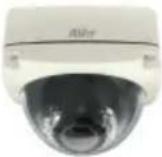 | 1. SF2111H-DVR |
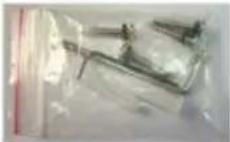 | 2. Accessory pack |
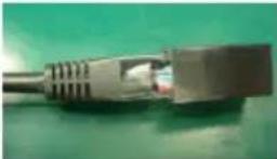 | 3. RJ45 socket |
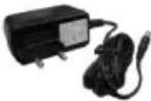 | 4. Power Adaptor(DC 12V/1A) (Optional) |
 | 5. CD (User's Manual and Quick Guide included) |
Optional accessory
| Item Descriptions | |
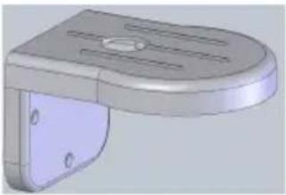 | Vandal Dome L type Bracket for bothSF2111H-DVR &SF2012H-DVWeight: 680g (N.W.)Material: AluminumColor: Silver-beigePackage: 24pcs in one carton |
Product Installation
Monitor Setting
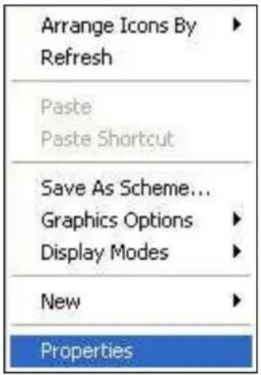
- Right-click on the desktop. Select "Properties"
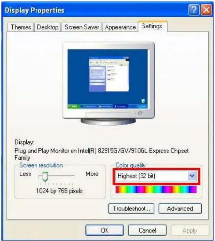
- Change "Color quality" to "Highest (32-bit)".
Hardware Installation and I/O Pin Assignment
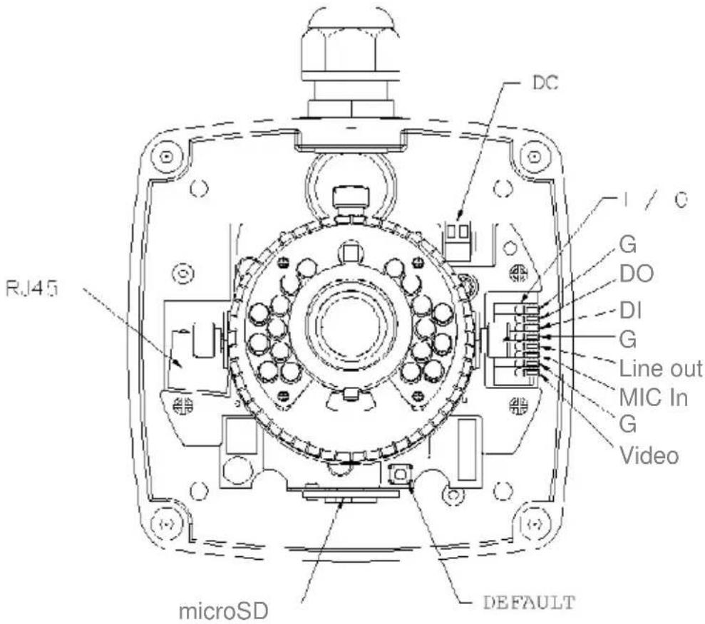
- Remove the dome cover, and you will see the structure as below.
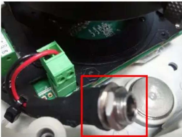
- Connect power adaptor, then connect the IP camera to PC or network. Set up the network configurations according to the network environment. The following picture shows a DC 12V connector for adapter jack plug.
natural_image
Close-up of a mechanical electronic component with green circuit boards and red wires, no visible text or symbols3. Installation Tips
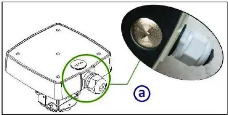
In order to ensure IP66 waterproof level, please install the vandal dome according to the instruction.
a. The Unused cable outlet hole must be closed, and the waterproof connector on the used hole must be locked closely
natural_image
Technical diagram of a mechanical component with a magnified inset showing internal components (no text or symbols)b. We recommend the bottom of housing be set on the smooth flat and closely seal with the surface.
c. When you mount the camera housing on the ceiling or wall, please use the screws with the black rubber o-rings. Without the o-ring, the water may seep into the machine.
d. Turn and loose the control stick, shift right and left to adjust the vari-focal lens until the image becomes clear, then turn and tighten the stick to fix it.
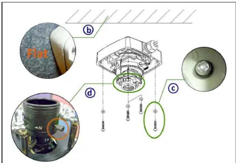
e. Use the 3-Axis bracket to adjust the camera to appropriate angle.
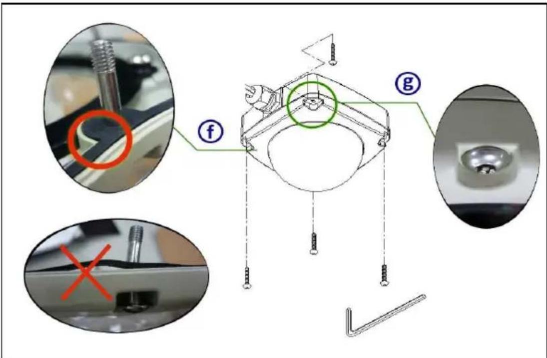
f. Before you close the dome cover, make sure that the black rubber band sticks to the inside of the cover completely. Crook or uneven rubber band may cause the waterproof defective.
g. Lock tightly the screws on the dome cover to ensure there's no gap between the lid and base.
4. I/O Interface
I/O Connection
a. Please connect the GND & DO pin to the external relay (buzzer) device.
b. Please connect the GND & DI pin to the external trigger device.
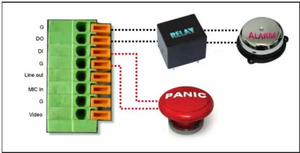
c. I/O PIN definition
■ GND (Ground): Initial state is LOW
■ DO (Digital Output): DC 5V
■ DI (Digital Input): Max. 50mA, DC 5V
Power Over Ethernet (PoE)
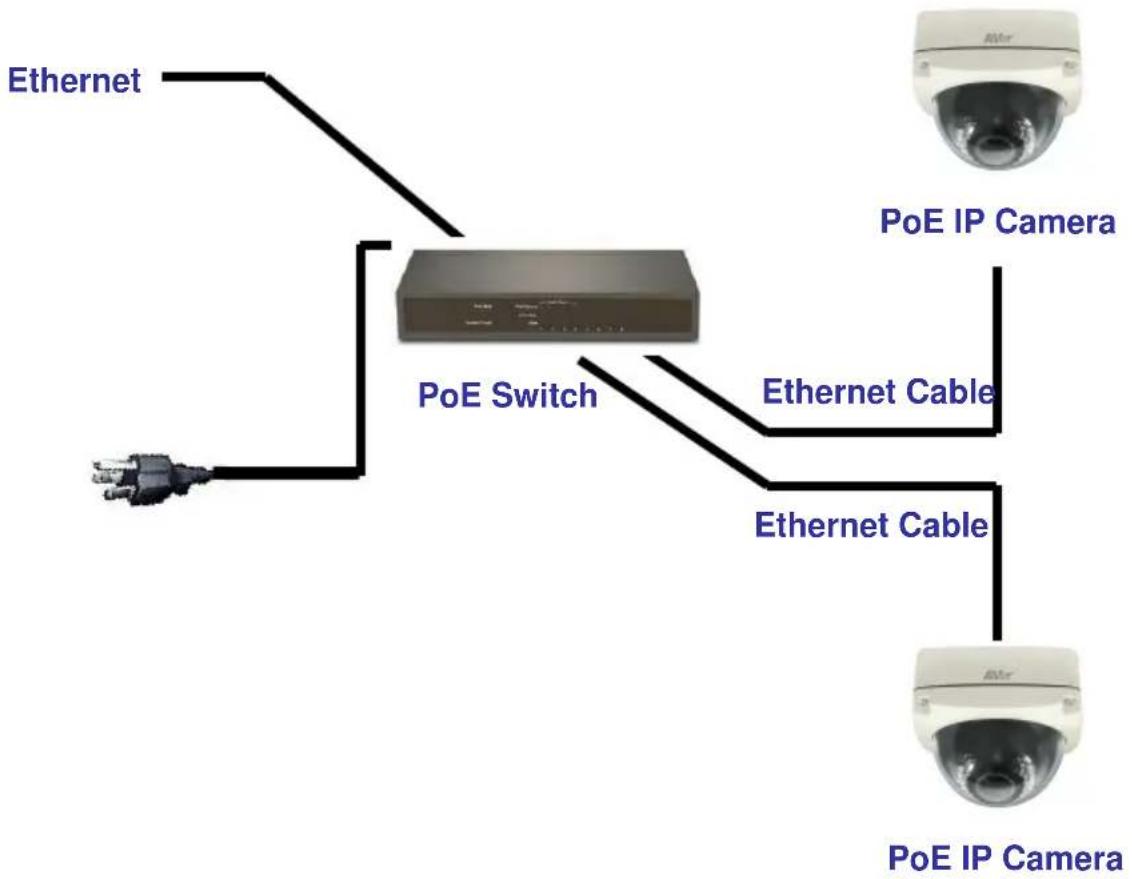
Set up the IP camera through Power over Ethernet (PoE). PoE is a technology that integrates power into a standard LAN infrastructure. It enables power to be provided to the network device, such as an IP camera, using the same cable as that used for network connection. It eliminates the need for power outlets at the camera locations.
[Note] 802.3at, 30W PoE Switch is recommended. We recommend users to purchase PoE switch from us to ensure the stability when using the IP Cameras. Please contact sales for more details.
flowchart
graph TD
    A["PoE IP Camera"] --> B["PoE Switch"]
    B --> C["Ethernet Cable"]
    B --> D["Ethernet Cable"]
    B --> E["Ethernet"]
    style A fill:#f9f,stroke:#333
    style B fill:#ccf,stroke:#333
    style C fill:#cfc,stroke:#333
    style D fill:#fcc,stroke:#333
    style E fill:#cff,stroke:#333
IP Assignment
There are two ways to find IP Camera:
– Finding IP Camera by using "NXU Lite recording software"
- Finding IP Camera by using "IP installer"
Finding IP Camera by using "NXU Lite recording software"
- The NXU Lite software is in the attached software CD. Before launching it, please install the software first. During the installing process, users will be required to input a User name and Password for login NXU Lite system. Users can define the User name and Password as wishes. Please refer to NXU Lite user manual for detailed installation instruction.
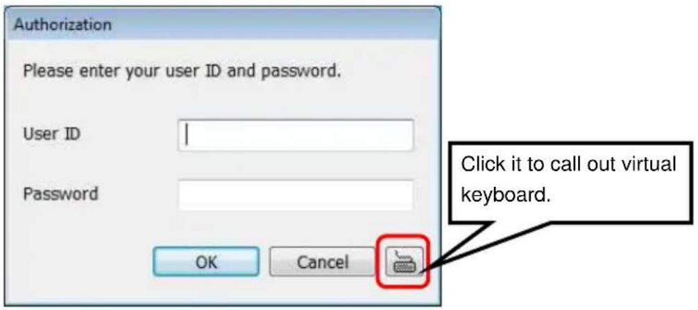
- To run the application, double-click on your PC desktop or click Start > Programs > DVR > NXU Lite. For security purpose, some of the features would require you to enter User name and Password before it can be accessed. When the Authorization dialog box appears, key in your User ID and Password. (If this is the first time, enter the one you have registered when installing the software.
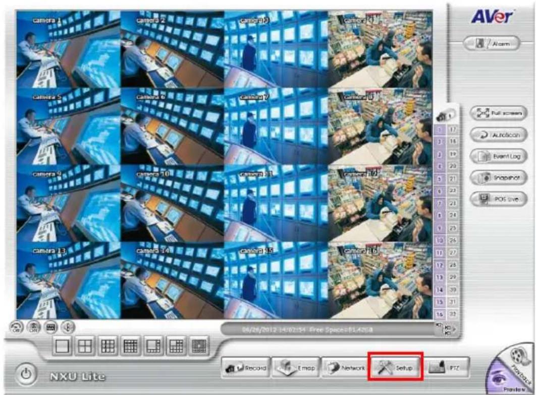
3. Click "Setup" button.
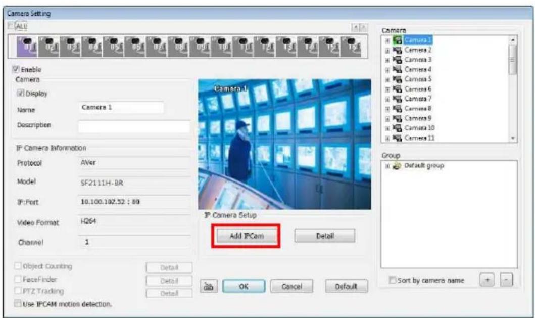
4. Click "Add IPCam" button.
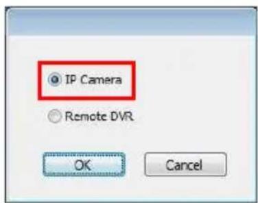
5. Select "IP Camera" item.
- Key in IP Camera's ID and Password (default is admin/admin) and click "Auto Search" to find camera.
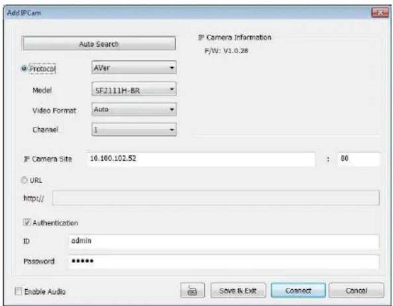
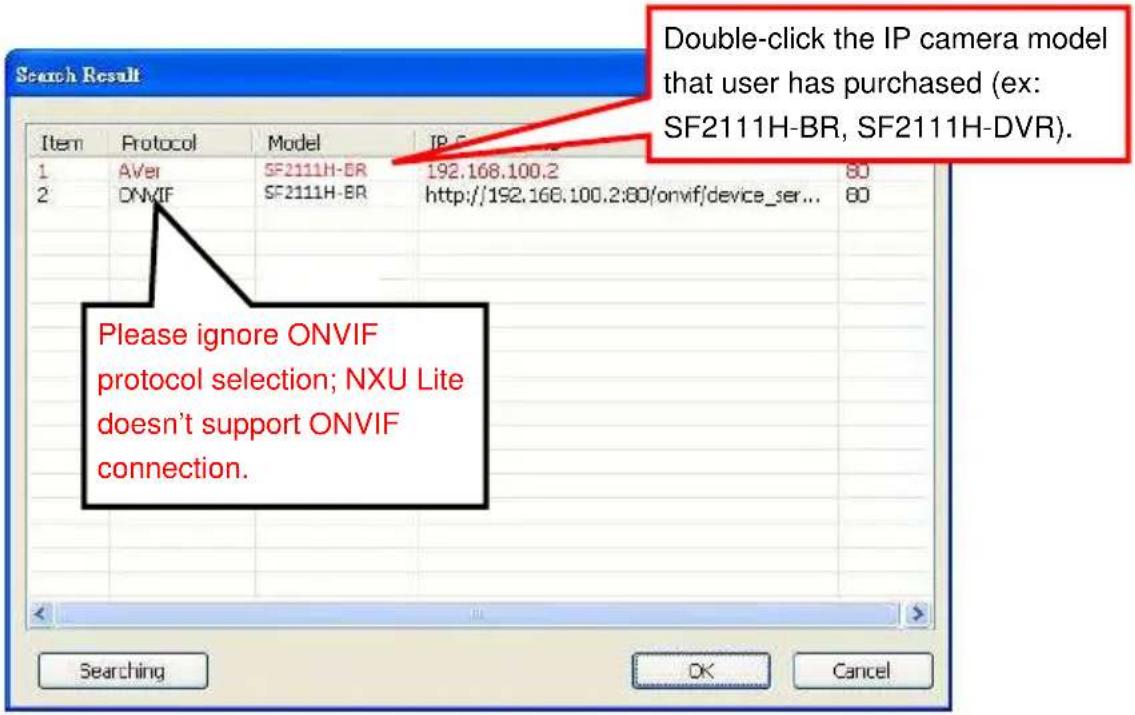
- In Search Result window, click it the IP camera model that user has purchased (Please ignore ONVIF connection item); the camera is in red text that is configurable. User can double-click on the camera is in red text and configure the IP camera's setting; even the IP camera is not in the same IP segment. Press "OK" to back to previous screen and press "Connect" to start live view.
Finding IP Camera by using "IP installer"
- Use the software, "IP Installer" to assign the IP address of the IP camera. The software is in the attached software CD.
- IP installer supports two languages
■ IPInstallerCht.exe: Traditional Chinese version
■ IPInstallerEng.exe: English version
- There are 3 kinds of IP configuration.
■ Fixed IP (Public IP or Virtual IP)
■ DHCP (Dynamic IP)
■ DHCP server/router network automatically assigns IP addresses to devices. You can use the IP Installer software in the CD to search for the IP camera(s) in the network.
■ Dial-up (PPPoE)
-
Execute IP Installer
-
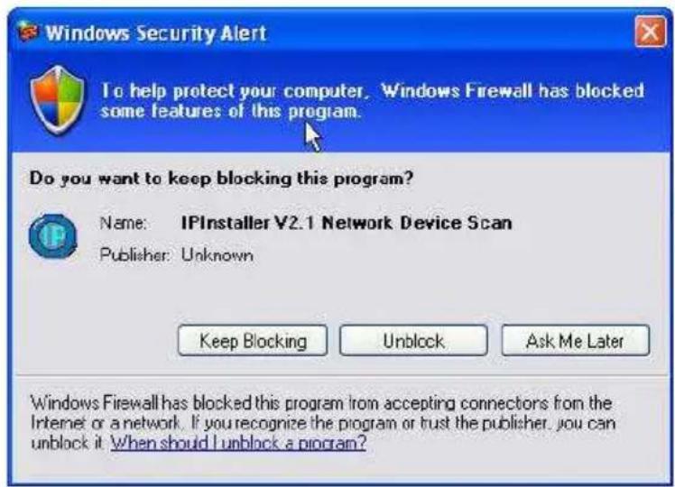
For Windows XP (SP2) users, the following message box may appear. Please click "Unblock".
IP Installer configuration:
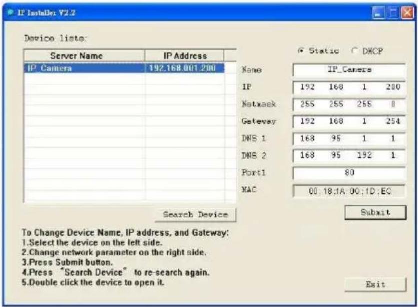
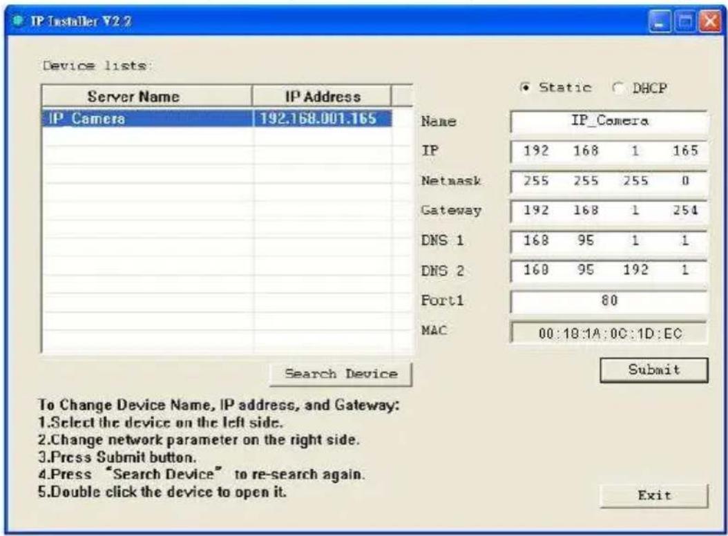
- IP Installer will search all IP cameras connected on the LAN. The user can click "Search Device" to search again.
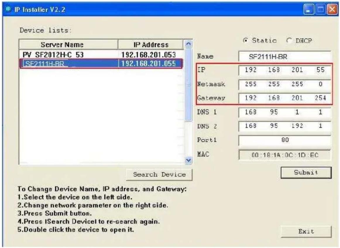
- Click one of the IP cameras listed on the left side. The network configuration for this IP camera will show on the right side. You may change the name of the IP camera to your preference (eg: Office, warehouse) in "Name" on the right side.
[Note] The server name length has to be less than 15 digits.
Using DHCP Server/Router Network
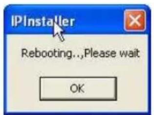
To use DHCP, please check DHCP and click "Submit" then click "OK". It will apply the change and reboot the Device.
Please left-click the mouse twice on a selected IP camera in "Device lists" in IP Installer. Upon doing so, the Internet Explorer browser should open.
Using NON-DHCP Server/Router Network
In Non-DHCP server/router network, the static IP address must be assigned to the device each time when adding another IP camera to the network; the default IP address of the current one must be changed to avoid conflict.
Please make sure the Subnet of the PC's IP address and the IP camera's IP address are the same.
[Example]
The same Subnet:
IP camera IP address: 192.168.1.200
PC IP address: 192.168.1.100
Different Subnets:
IP camera IP address: 192.168.2.200
PC IP address: 192.168.1.100
To Change PC IP Address:
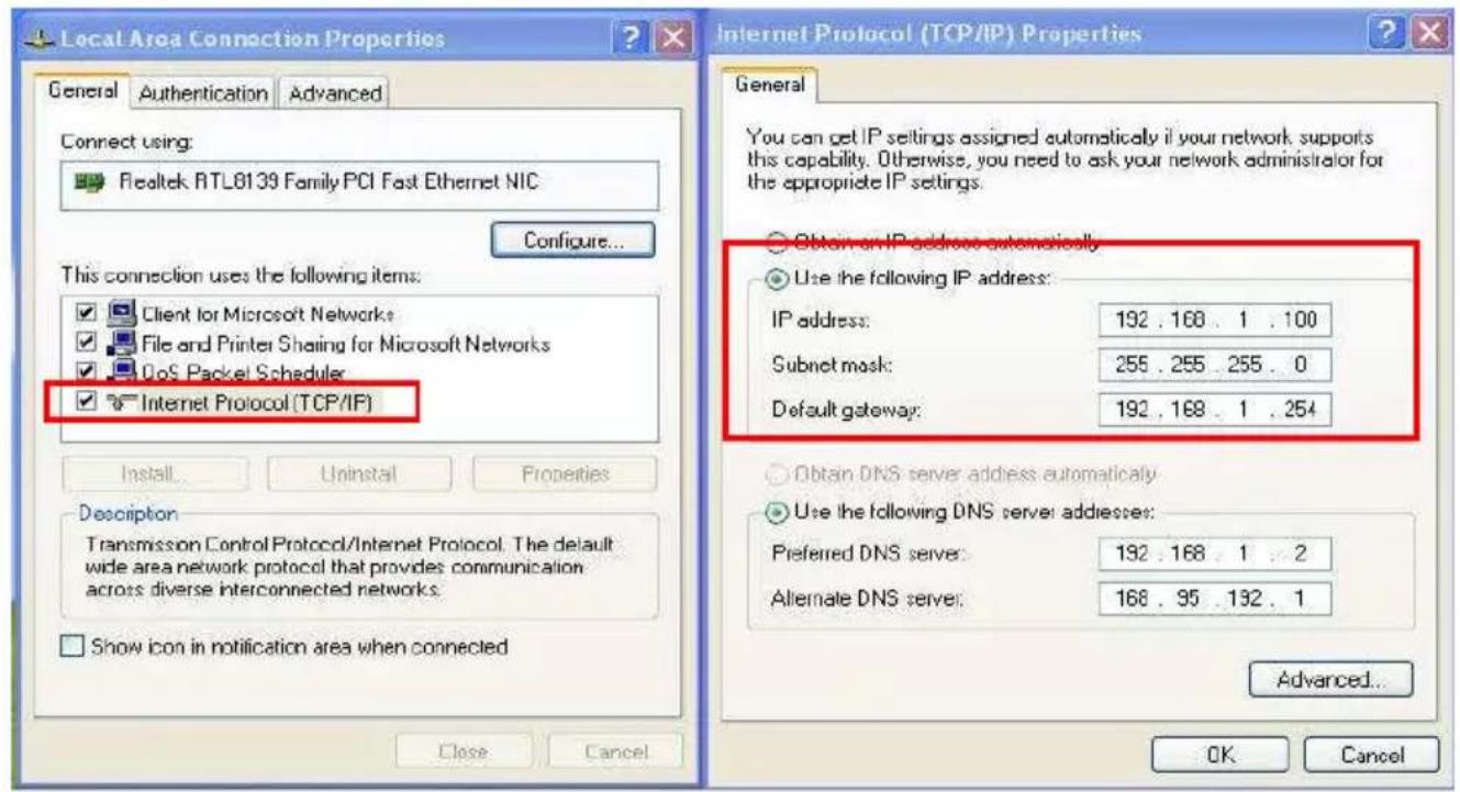
Control Panel→Network Connections→Local Area Connection Properties→Internet Protocol (TCP/IP) →Properties
Please make sure your IP camera and PC have the same Subnet. If not, please change IP camera subnet or PC IP subnet accordingly.
PC's IP address:
IP camera IP addresses:
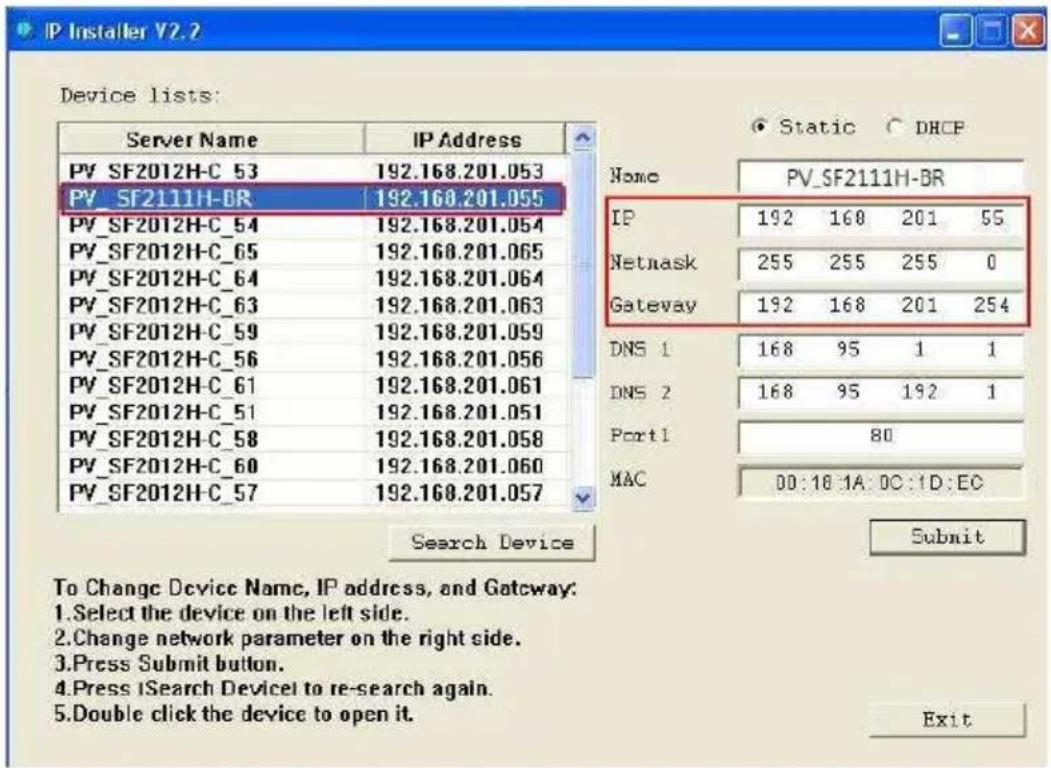
- A quick way to access remote monitoring is to left-click the mouse twice on a selected IP camera in "Device lists" in IP Installer. Upon doing so, the Internet Explorer browser should open.
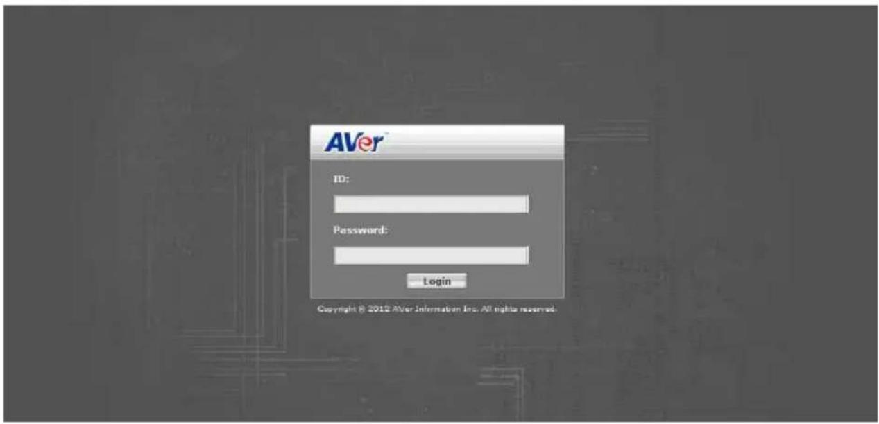
- Then, please key in the default "User name" and "Password", both of which are "admin".
Install ActiveX Control
The first time you attempt to view the camera video via Internet Explorer, it will ask you to install the ActiveX component.
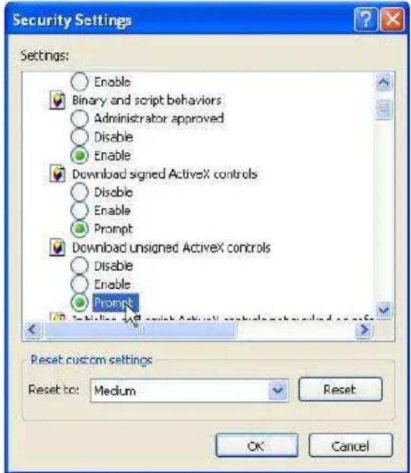
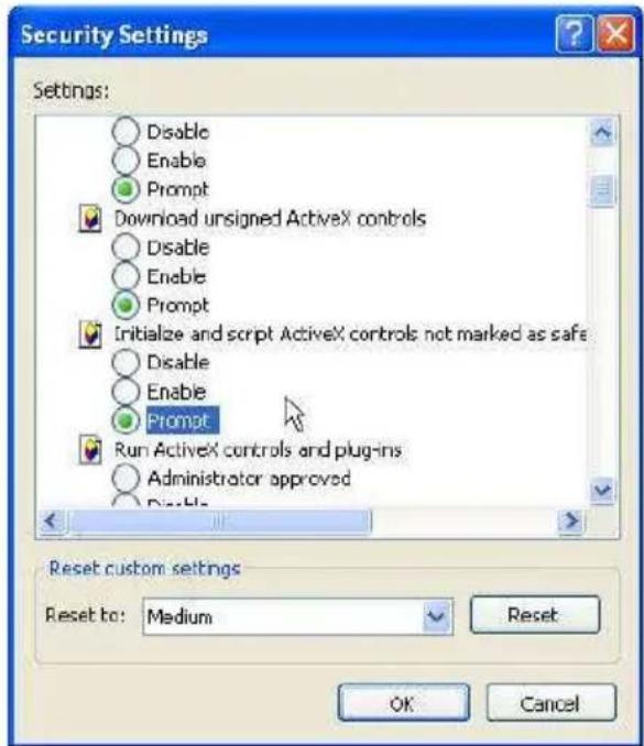
If the installation fails, please check the security settings for the Internet Explorer browser.
-
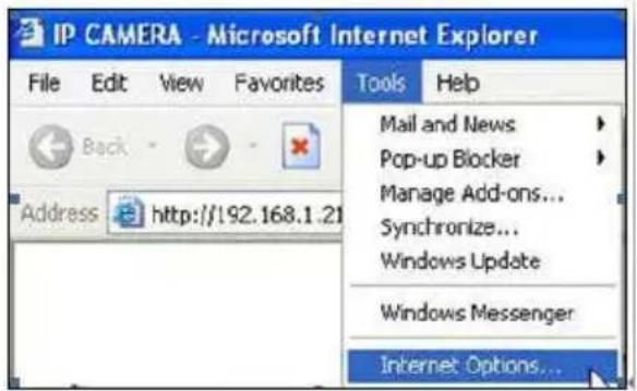
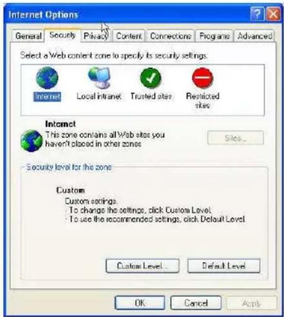
IE → Tools → Internet Options... → Security Tab → Custom Level... → Security Settings → Download unsigned ActiveX controls → Select "Enable" or Prompt.
-
IE → Tools → Internet Options... → Security Tab → Custom Level... → Initialize and script ActiveX controls not marked as safe → Select "Enable" or Prompt.
1 2
3 4
5
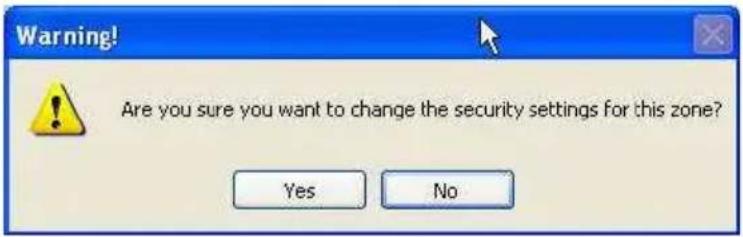
When the following dialogue box appears, click "Yes".
Using the IP Camera Browser Interface
The admin have the full access to the IP camera browser interface. The menu on the left, you can expand and navigate to access all the features.
Preview
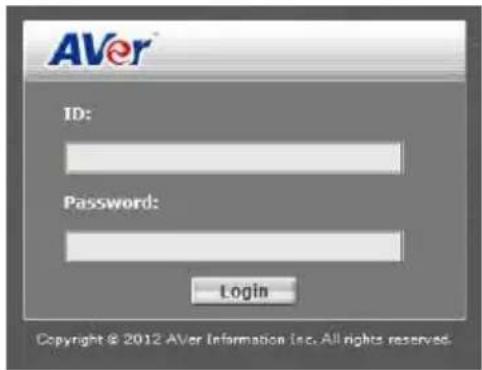
Launch the Internet Explorer browser, type the IP address of the IP camera in the address field. It will show the following dialogue box. Key-in the "ID" and "Password". The default "ID" and "Password" are both "admin".
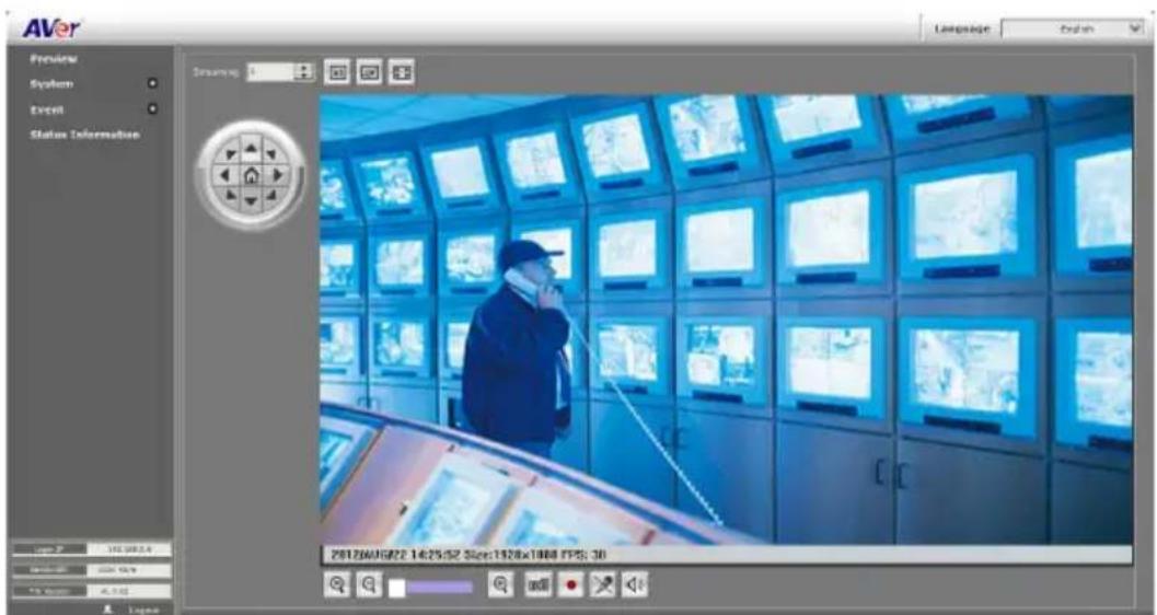
Once connected to the IP camera, the following program interface will appear.
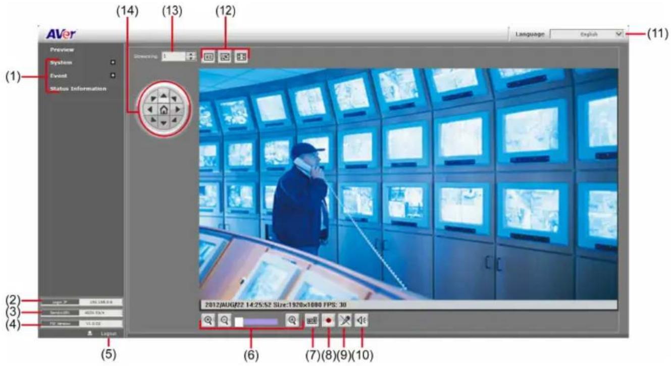
Name Function
| (1) System/Event/Status Information | Set up IP camera's configuration. |
| (2) Login IP | Show PC's IP address |
Name Function
| (3) Bandwidth | Show current IP camera's transmitting bandwidth |
| (4) FW Version | Show IP camera's current firmware version |
| (5) Logout | Exit the application |
| (6) Zoom control |  Reset zoom level. Reset zoom level. |
 Increase zoom level. Increase zoom level. | |
 Decrease zoom level. Decrease zoom level. | |
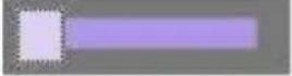 Use the scroll bar to zoom in or zoom out the video screen Use the scroll bar to zoom in or zoom out the video screen | |
| (7) Capture |  Capture and save the image on the screen in *.bmp format Capture and save the image on the screen in *.bmp format |
| (8) Record |  Start/stop audio and video recording. The recorded video will be saved in *.avi format. Start/stop audio and video recording. The recorded video will be saved in *.avi format. |
| (9) 2-way Talk |  Click the Microphone button to talk to IP camera side from user site. Click this button again to mute this function. Click the Microphone button to talk to IP camera side from user site. Click this button again to mute this function. |
| (10) Speaker |  Turn on the PC's speaker so that PC side can hear sound from IP camera side. Click this button again to mute this function. Turn on the PC's speaker so that PC side can hear sound from IP camera side. Click this button again to mute this function. |
| (11) Language | Select the browser interface language. |
| (12) Video screen | Change the video screen display. |
 Display the actual video pixel size Display the actual video pixel size | |
 Display the video screen in compact size. Display the video screen in compact size. | |
 Display the video in full screen mode. Press ESC to exit full screen mode. Display the video in full screen mode. Press ESC to exit full screen mode. | |
| (13) Stream | Switch to view the video stream type. The IP camera can send multiple video streams of up to 3 types. To change the video stream setting, go to System > Video Stream.[Notes]When streaming 2 setting in "Video Setting" is closed, there won't have other stream option |
| (14) Direction Controller | Move the position of the view point while in zoom mode. User has to zoom in first. |
System > General
In this section, only admin level is authorized to configure the IP camera system maintenance and the date and time settings.
System > General > Maintenance
In the Maintenance tab, the administrator can check the system event log, upgrade the system firmware, reset the configuration settings without having to change the user management and network settings, reboot, and restore all back to factory default settings.
![AVer Language English Preview System General User Management Network Setting Advance Image Video Stream Audio SD Card Event Status Information Login ID 10.100.200.23 Bandwidth ---- Kb/s FW Version V1-0.01 Logout Maintenance Date & Time Export Settings: Click the following button to export all configuration settings to a file. Reboot: Click following button to reboot the device. Factory Default: Click the following button to reset all configuration settings to their default values. Firmware Upgrade: Browse... Import Setting: Browse... System Logs: [2012/07/09 14:48:45] 192.168.201.1 login by admin. [2012/07/09 13:27:32] Network connection fail. [2012/07/09 13:06:40] 192.168.201.1 login by admin. [2012/07/09 13:02:33] Network Re-connected. [2012/07/09 13:01:29] Network connection fail. [2012/07/09 12:30:44] Network Re-connected. [2012/07/09 12:30:42] Network connection fail. [2012/07/09 12:30:03] Network Re-connected. [2012/07/09 11:51:52] Network connection fail. [2012/07/09 11:51:51] Network Re-connected. [2012/07/09 11:51:49] Network connection fail. [2012/07/09 11:21:04] 192.168.201.1 login by admin. [2012/07/09 11:06:36] 192.168.201.1 login by admin. [2012/07/05 10:44:40] Network connection fail. [2012/07/09 10:38:41] 192.168.201.1 login by admin. [2012/07/05 10:36:17] 192.168.201.1 login by admin. Export Reboot Restore Upgrade Upgrade (1) (2) (3) (4) (5) (6)](/content/2026/05/905101/images/79572648d63d0db633d4989cce6f9f15a07b017311871e9b9bd48153c584e062.jpg)
Name Function
| (1) Export Settings | Upload to save all the configuration settings from the IP camera to computer hard disk. |
| (2) Reboot | Turn the IP camera off and on again. |
| (3) Factory default | Set all the configuration settings back to default except the user management and network settings. |
Name Function
(4) Firmware Upgrade
Upgrade the firmware to the latest version.
To Upgrade the IP Camera Firmware
- Download the file from our website and save it in your computer hard disk.
- Click Browse. Locate and select the file and click Open.
- Click Apply. Wait till you see the massage
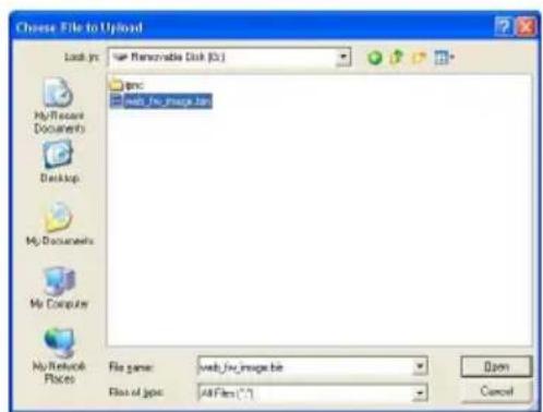
"Firmware Upgrade OK!!". You may now click the Internet Explorer browser refresh button or press F5. The login page will appear.
New firmware download OK!
It is strongly recommended to stop any unnecessary jobs while updating firmware.
Please be patient and the updating process may take a long time.

Writing Progress:100%
Firmware upgrade complete.
| (5) Import | Download to replace the current settings with the configuration settings file from the computer hard disk to IP camera. |
| (6) System log | Display the IP camera system event log. |
System > General > Date & Time
In the “Date & Time” tab, the administrator can set and update the system's date and time. After filling in the correct settings, click Apply to apply the new settings.
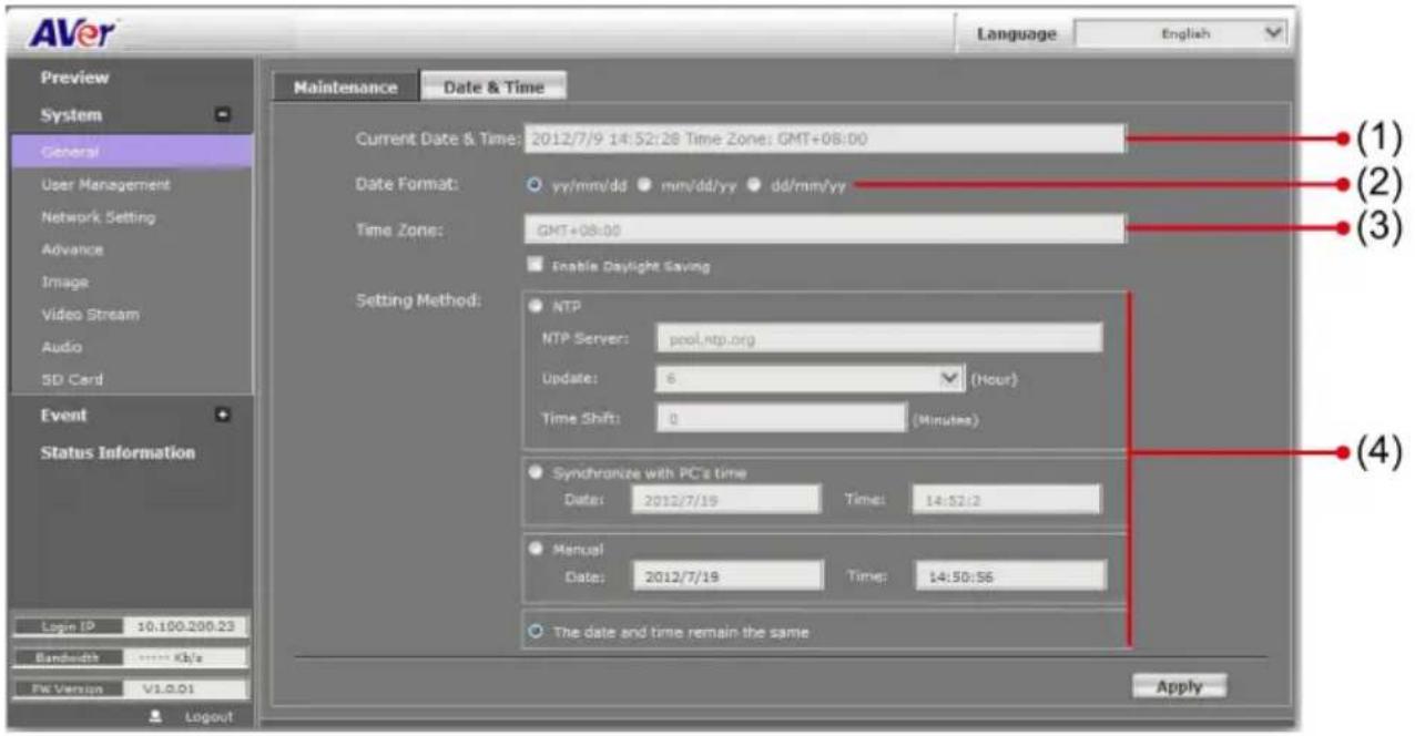
Name Function
| (1) Current Date & Time | Display the current date and time. |
| (2) Date Format | Select the date display format. |
| (3) Time Zone | Set the local time zone. Check the box next to “Enable Daylight Saving” to enable and setup the start date and end date for daylight saving time. |
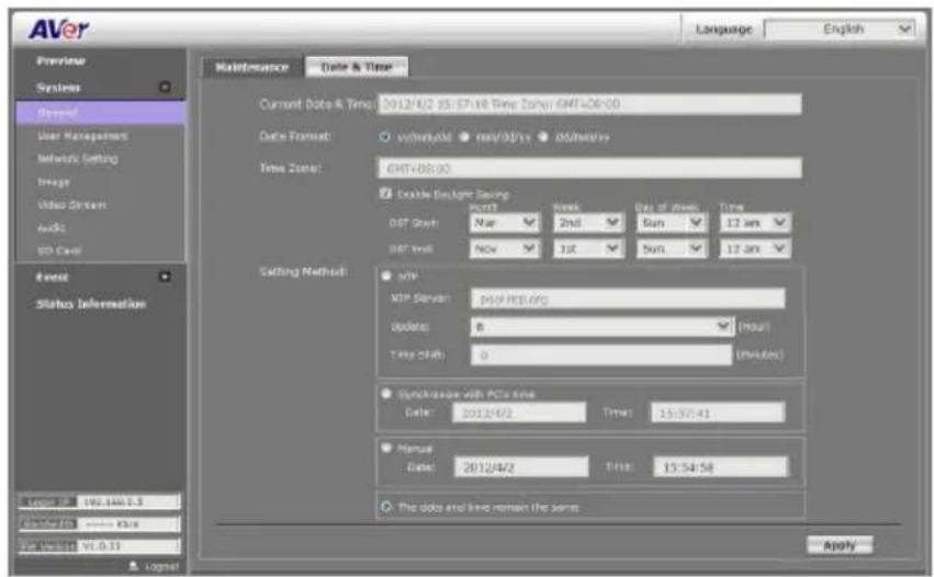
Name Function
(4) Setting Method
Select the date & time settings method.
Sync with current PC – Obtain the date and time setting on the current login computer.
Sync with NTP Server – Obtain the date and time setting from NTP server. In the drop-down list, select the NTP host name.
Manual – Manually set the date and time. Click "Done" to close the date and time interface.
System > User Management
In this section, only admin level is authorized to create, delete, and edit the account in Account tab and configure the client connection setting in Connection tab.
System > User Management > Account
IP camera supports two different user accounts – Administrator (Admin) and Guest User.
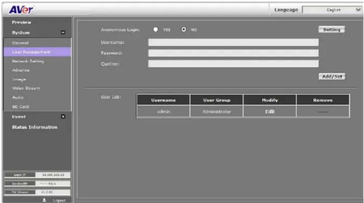
User Type Access Rights
Admin Can access all the configuration pages
Guest User Can only access the preview and status information pages.
■ Anonymous User Login
√ Yes: Allow an anonymous user to view the IP camera without logging in.
√ No: Need user name & password to access this IP camera
- Add user: Enter the user name in "Username", the password in "Password", and re-enter the password in "Confirm". Then, click "Add/Set".
■ User List: Click edit to change the account password. To delete the user account, click Remove button.
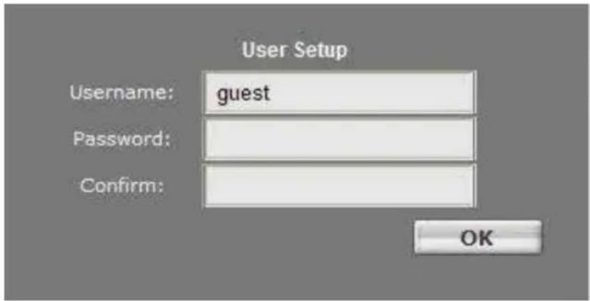
[Note]
- The password can't be empty, otherwise, user are not able to login successfully.
- Please don't use special symbols as user name such as *, %, \$, &.
System > Network Setting > Setting
■ Device Name: Used to name the IP camera to search more easily for this specific one among all connected IP cameras.
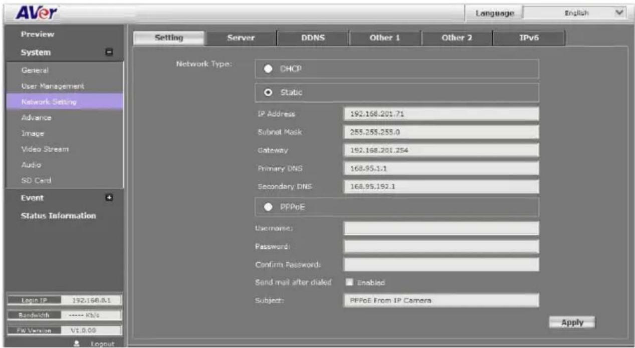
■ Network Type: IP camera supports DHCP, static IP and PPPoE. After completed all settings, click Apply to save the configuration.
- DHCP: Using DHCP, IP camera will get all the network parameters from DHCP server automatically.
- Static IP: Please enter the IP address, subnet mask, gateway, Primary DNS, and Secondary DNS.
- PPPoE: Enter the Username, Password and re-enter Password in Confirm Password for the ADSL connection. And then click Apply to save the configuration.
System > Network Setting > Sever
Used to send out the video via Email or FTP, or to save on NAS.
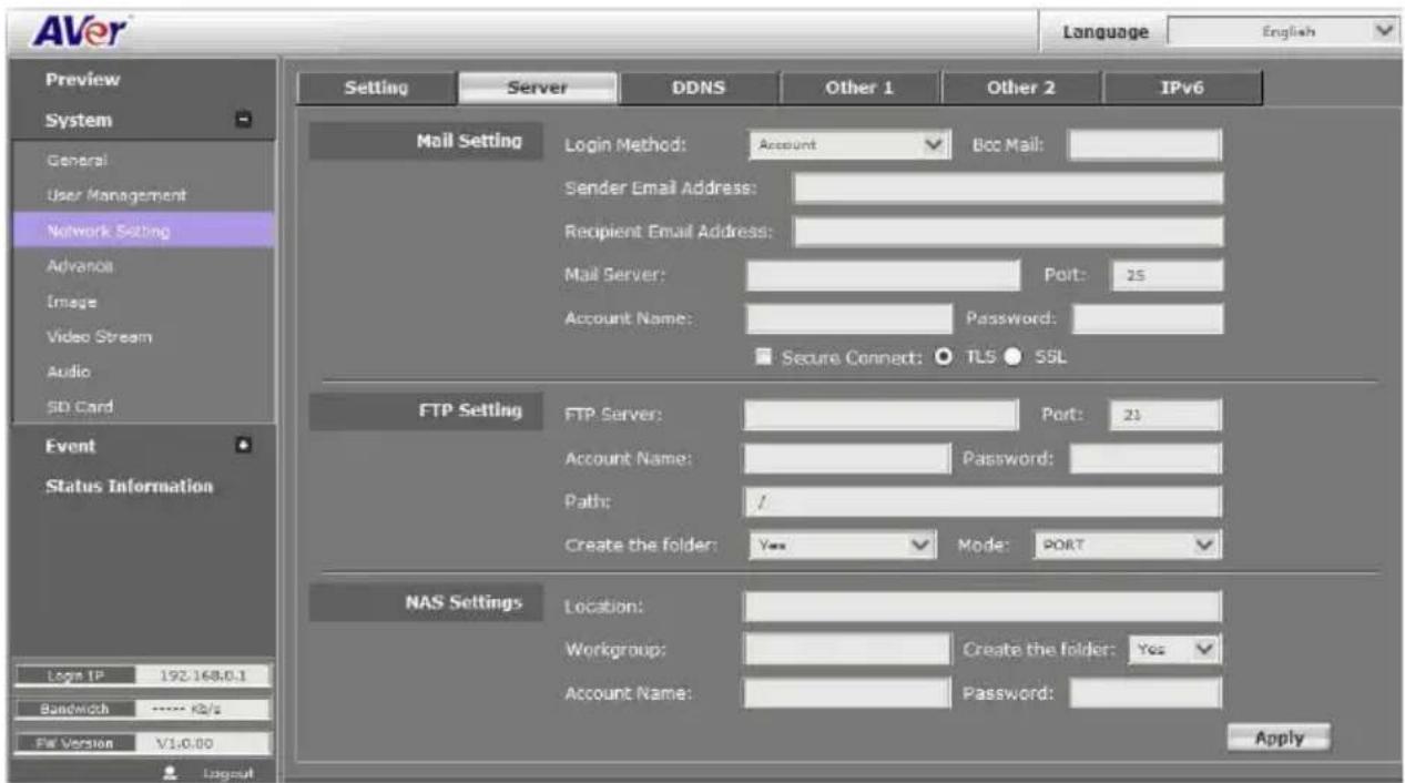
Mail Setting: Used to send out the video via Email.
a. Login Method: Click drop-down list to select the method to login Email server – “Account” or “Anonymous”.
b. Enter necessary information in "Bcc Mail", "Sender Email Address", "Recipient Email Address", "Mail Server", "Mail Server Port", "Account Name", and "Password" columns.
c. Click "Apply" to save the configuration.
■ FTP Setting: Used to send out the video to FTP server.
a. Enter necessary information in "FTP Server", "Account Name", "Password", and "Path" columns.
b. Port: Select the FTP server port.
c. If the user wants to create a new folder on the FTP server to save the video file, select "Yes" under the "Create the folder".
d. Mode: Select the FTP transmission mode.
e. Click "Apply" to save the configuration.
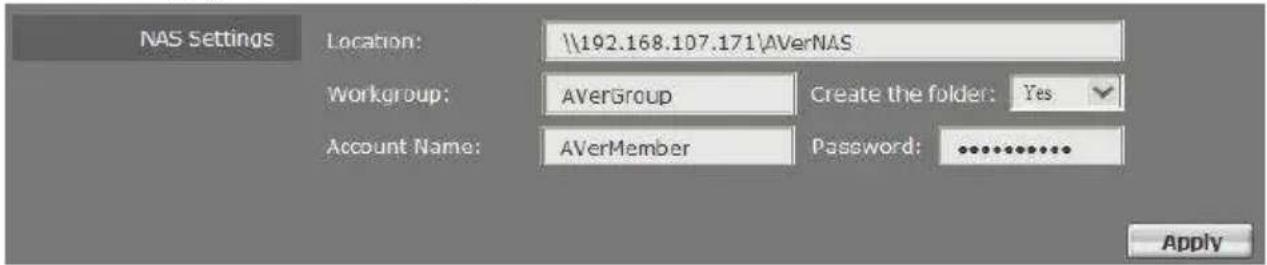
■ NAS Settings: Used to send out the video to NAS server.
a. Enter necessary information in "Location", "Workgroup", "Account Name" and "Password" columns.
b. If the user wants to create a new folder on the NAS server to save the video file, select "Yes" under the "Create the folder".
c. Click "Apply" to save the configuration.
System > Network Setting > DDNS
The IP camera supports DDNS (Dynamic DNS) service.
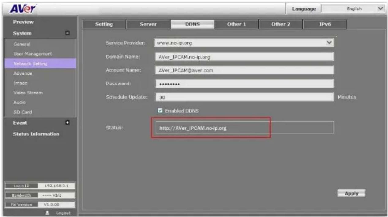
a. Select "Enabled DDNS" to enable DDNS function.
b. Enter the Domain Name, Account Name, and Password that the user has registered on the DDNS service provider in the appropriate columns.
c. Enter the IP refreshing time period in the "Schedule Update" column.
d. Click "Apply" to save the configuration.
[Note] If you set up schedule update to occur too frequently, the IP may be blocked. In general, performing schedule update once a day (1440 minutes) is recommended.
Status
- Common warning message:
Updating!
Failed(1), Please check your DNS setting.
Failed(2), Please check your internet connection.
Failed(3), Please check your internet connection.
Failed(6), receiving data failure
- Warning message from different service provider:
Server Provider : dyndns.org
Failed(4), Please check the Dyndns.org.
Error : The system parameter given is not valid.
Error : No user agent was specified.
Error : The username and password pair do not match a real user.
Error : An option available only to credited users was specified.
Error : Not in the form hostname.domain.org or domain.com.
Error : The hostname specified does not exist.
Error : Not under the username specified.
Error : Too many or no hosts specified in an update.
Error : The hostname specified is blocked for update abuse.
Error : DNS error encountered.
Error : DNS Server Error Conditions.
Server Provider : ddns.camddns.com(TW)
Failed(5), The name has already been registered.
Server provider : ddns.ipddn.com(HK)
Failed(5), The name has already been registered
Server provider : www.3322.org.
Failed(4), Please check the www.3322.org.
System > Network Setting > Other 1
![AVER Language English Preview System General User Management Network Setting Advance Image Video Stream Audio SD Card Event Status Information Login IP: 192.168.0.1 Bandwidth ...... Kb/s FW Version V1.0.00 Server DDNS Other 1 Other 2 IPv6 HTTP Port: 80 HTTPS Port: 443 UPnP Support: Yes No UPnP Port Forwarding: Yes No External HTTP Port: 80 External HTTPS Port: 443 External RTSP Port: 554 RTSP Server: Yes No RTSP Port: 554 RTP Start Port: 5000 [1024..9997] RTP End port: 9000 [1027..10000] ONVIF: v1.02 v1.01 Disabled Security: Yes No RTSP Keepalive: Yes No Apply](/content/2026/05/905101/images/9847e888b460ee8b76a0c755273edb48e0b3a983919d38fd044ca07364b6d805.jpg)
User may need to assign different port to avoid conflict when setting up IP assignment. Click Apply to save the configuration.
- HTTP Port: setup web page connecting port and video transmitting port (Default: 80)
■ HTTPS Port: AVer IP Camera supports encrypted browsing using HTTPS. This is configured on the System > Advance > HTTPS
■ UPnP Support: This IP camera supports UPnP, if this service is enabled on your computer, the camera will automatically be detected and a new icon will be added to "My Network Places."
[Note] UPnP must be enabled on your PC.
Please follow the procedure to activate UPnP.
- Open the Control Panel from the Start Menu.
- Select Add/Remove Programs.
- Select Add/Remove Windows Components and open Networking Services section.
- Click Details and select UPnP to setup the service.
- The IP device icon will be added to "My Network Places".
- User may double click the IP device icon to access IE browser.
■ UPnP Port Forwarding: If the IP camera is set up behind the firewall, please select YES to enable it.
■ RTSP Server: Enable/disable RTSP function. The Real Time Streaming Protocol (RTSP) is a network control protocol designed for use in entertainment and communications systems to control streaming media servers.
■ RTSP Port: setup port for RTSP transmitting (Default: 554)
■ RTP Start and End Port: in RTSP mode, you may use TCP and UDP for connecting. TCP connection uses RTSP Port (554). UDP connection uses RTP Start and End Port.
■ ONVIF: User can enable ONVIF standard and select the ONVIF version or disable it.
■ Security: Yes is required account and password to connect with this IP camera through ONVIF protocol. No is not required account and password to connect. (Make sure the NVR system supports ONVIF v1.02.)
■ RTSP Keepalive: To keep connection until remote site disconnects it.
System > Network Setting > Other 2
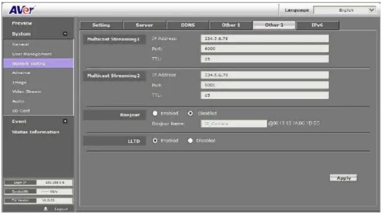
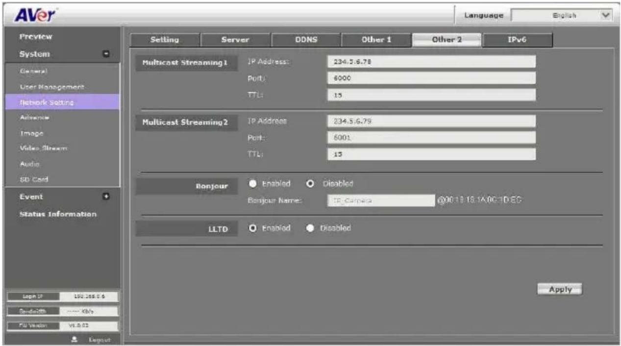
Multicast Setting (based on the RTSP Server): User can setup two streaming based on the RTSP Server.
Multicast operation example:
The application is to get the multicast streaming in the LAN environment. Basically, the users operate VLC player, and then you can get the multicast streaming form IP camera.
Please follow the steps to obtain the multicast streaming in the following steps:
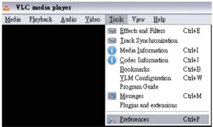
Step 1:
- Implement VLC player (please download from the internet)
- Select /tools/preferences
Step 2:
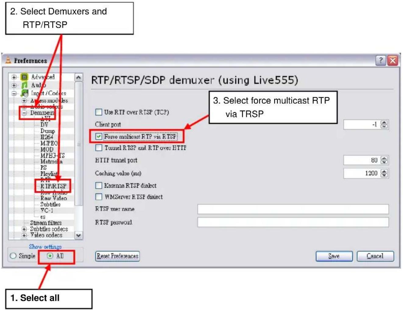
Step 3:
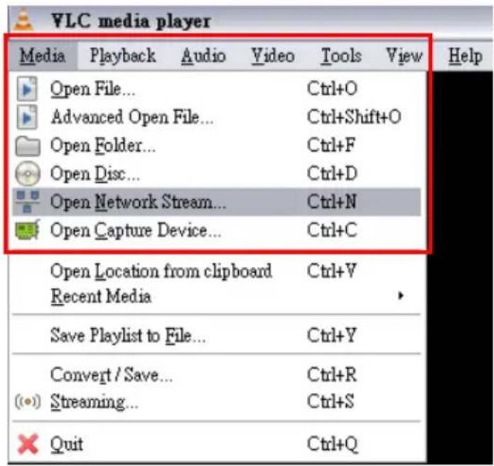
Select Media/open network stream
Step 4:
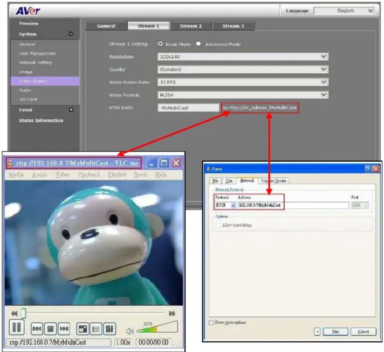
Input rtsp://[IPCAM Address] / [RTSP Path]
The URL address should be the same as the RTSP path in Video Stream (System-->Video Stream)
[Notice]
a. If the received image is not from the required IP camera, please adjust the value. (Change either IP Address or Port number)
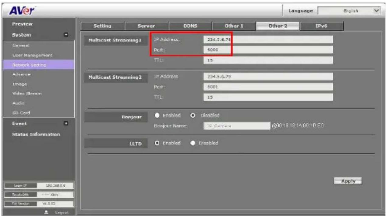
b. If the Multicast stream you use doesn't support RTSP Keepalive, please select NO.
![Aver Language English Preview System General User Management Network Setting Advance Image Video Stream Audio SD Card Event Status Information Login IP 192.168.0.1 Bandwidth ---- kb/s Pv Version V1.0.00 Setting Server DDNS Other 1 Other 2 IPv6 HTTP Port: 80 HTTPS Port: 443 UPnP Support: Yes No UPnP Port Forwarding: Yes No External HTTP Port: 60 External HTTPS Port: 443 External RTSP Port: 554 RTSP Server: Yes No RTSP Port: 554 RTP Start Port 5000 [1024..9997] RTP End port: 9000 [1027..10000] ONVIF: v1.02 v1.01 Disabled Security: Yes No RTSP Keepalive: Yes No Apply](/content/2026/05/905101/images/b26348ff8a44730df0b216c155ec96015ca202bf64b301d9ef6b3d188bd22fa6.jpg)
■ Bonjour: This function enables MAC systems to link to this IP Camera. Please key in the name here.(Safari supports Bonjour protocol)
■ LLTD: If your PC supports LLTD, enable this function then you can check the connection status, properties, and device position (like IP address) of this IP Camera in the network map. In the computer running Windows Vista or Windows 7, you can find LLTD through the path Start → Control Panel → Network and internet → Network and Sharing Center → Click “See full map”.
System > Advance > HTTPS
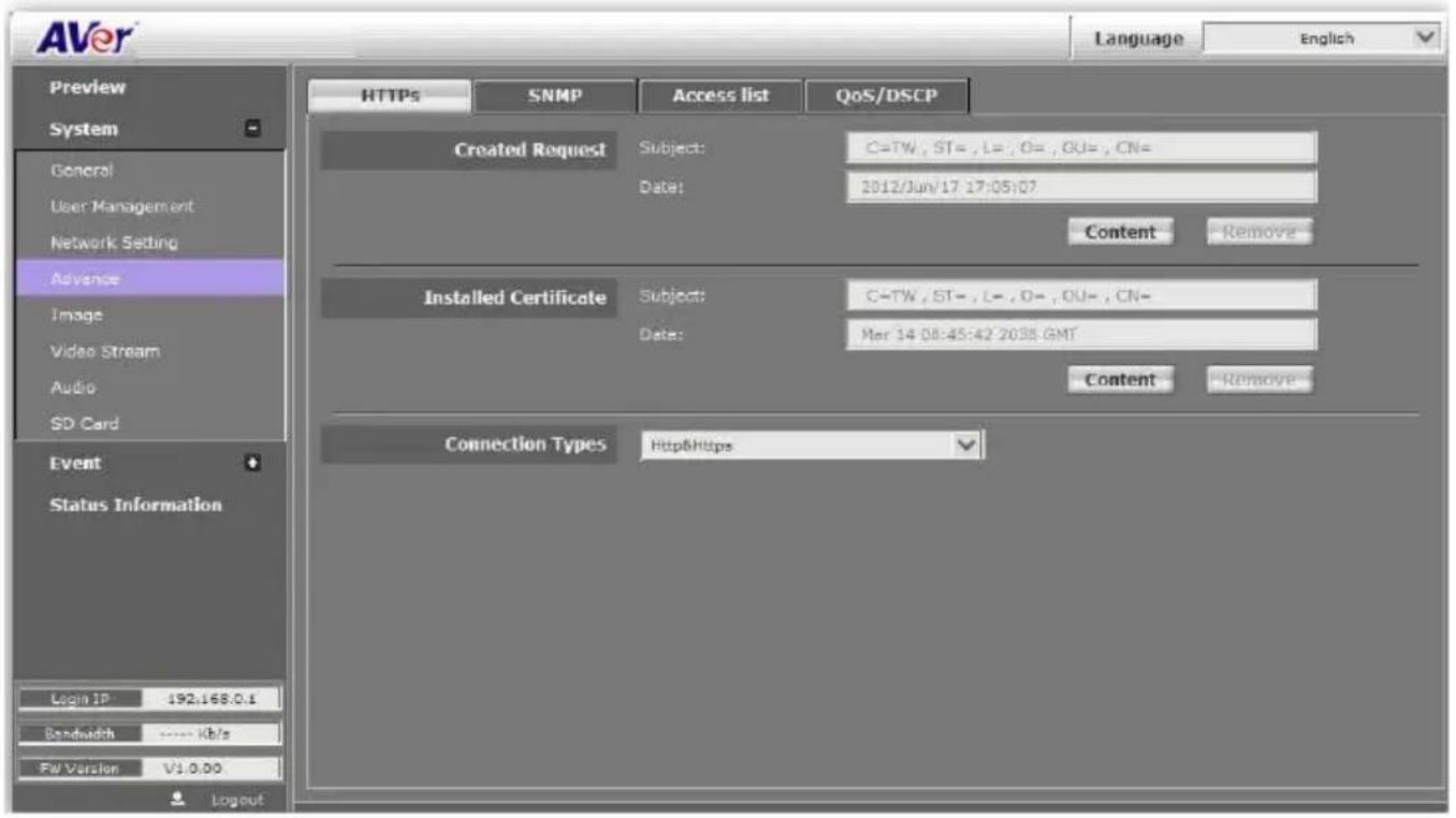
HTTPS (Hypertext Transfer Protocol Secure): Https can help protect streaming data transmission over the internal on the higher security level. You can select the connection type. "Https" means user cannot connect the camera via Http protocol. The HTTPS path will be: "https :/( IP address) /". If you select "Http & Https", both the Http and HTTPS path can be used to access the camera

Remove the existing setting: Before setting new request, please remove old secure identification. Select "Http" connection type and click "Remove".
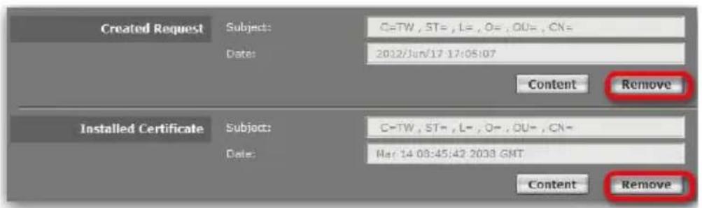
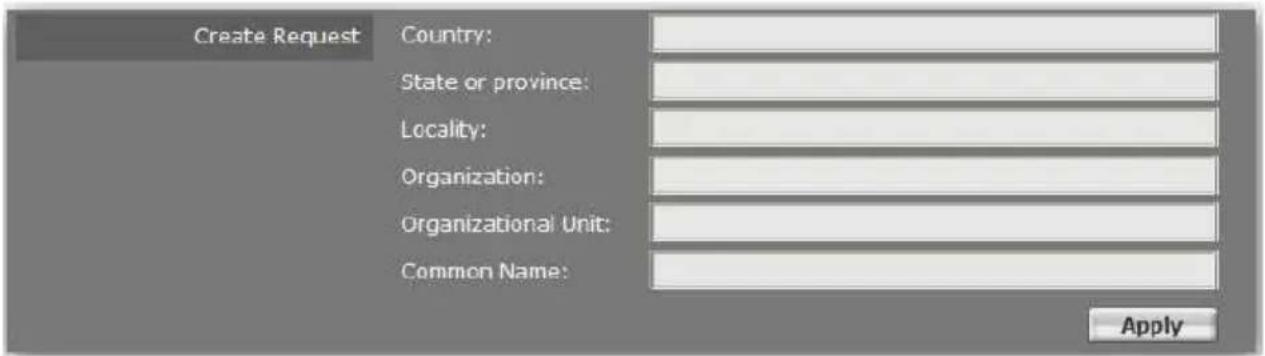
Created Request: Setting the secure identification and apply it.
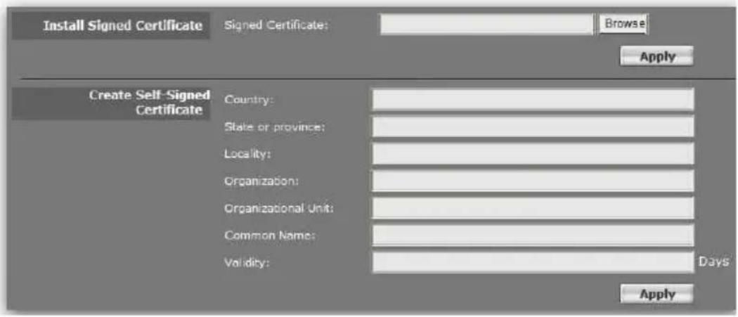
There are two ways to set Certificate- Install Signed Certificate or Create Self-Signed Certificate.
System > Advance > SNMP
SNMP (Simple Network Management Protocol) provides a simple framework for administering networked hardware. To manage the IP camera, you have to prepare a MIB browser or similar tools first. SNMPv1, SNMPv2c, and SNMPv3 can be enabled simultaneously.
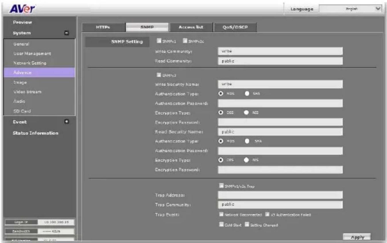
■ SNMPv1 and SNMPv2: The term "Community name" in SNMPv1 and SNMPv2c can be roughly regarded as key. The person who has the community name has the authority to read or edit the information of IP camera via SNMP. Check the box to enable SNMPv1 or SNMPv2c protocol, and specify the community name for write (read and write) and read (read-only). The user who uses read community name to access the IP camera cannot modify any data of this camera.

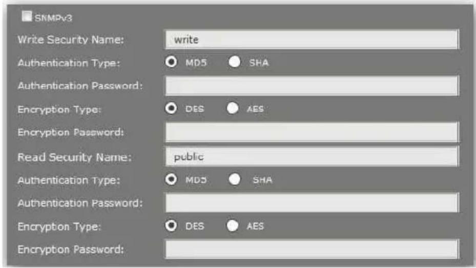
SNMPv3: For data security reason, the authentication and encryption assurances are added when developing SNMPv3. The user has to give not only the security name (the same as "community name" in v1&v2c, or sometimes we call it "context name") but the password in order to access the IP camera. Please set security name, authentication type, authentication password, encryption type, encryption password of write and read respectively. The password must be 8\~64 bits in length. Different from in SNMPv1 and v2c, the user have to create a account when using SNMPv3. In the account parameters, key in the security name and password you set in the camera to get accessing.
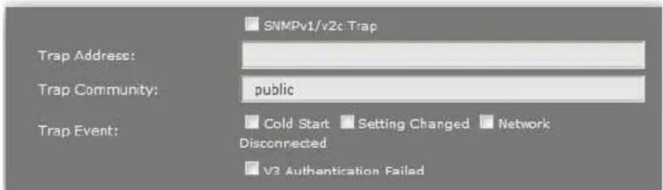
SNMPv1/v2cTrap: Trap is a mechanism that allows the managed device to send messages to manager instead of waiting passively for polling from the manager. Specify the trap event. When those events happen, the camera will send the ring message to the Trap Address, which is usually the manager's IP address. Trap Community means the community that can receive the trap message.
- Cold Start: The camera starts up or reboots.
- Setting changed: The SNMP setting is changed.
- Network Disconnected: The network connection was broken down. (The camera will send trap messages after the network being connected again)
■ V3 Authentication Failed: A SNMPv3 user account tries to get authentication but failed. (Due to incorrect password or community)
■ SD Insert / Remove: A microSD/SDHC card is inserted or removed.
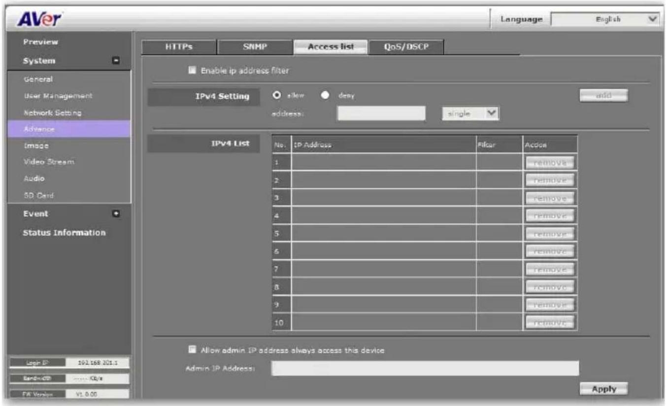
System > Advance > Access list
You can deny an IP address or a range of IP address so that they cannot access the IP camera. Tick the "enable" box, key in the IP address you want to deny, select" deny" then click "Add" to add it to the list. You can also choose to deny a range of IP address but allow one or several IP address of them. Take the picture above for example, IP address192.168.50.151\~161 is not allowed to connect to the camera, but only 192.168.50.159 can access. Note: In the list "allow" condition must be ranked before "deny" condition. For example, if we exchange the sequence, set "Deny: 192.168.50.151 \~ 192.168.50.161" for the first item and "Allow: 192.168.50.159" for the second item in the list, the IP "192.168.50.159" turns out to be denied by the camera because the "deny" condition has the priority according to our ranking way.
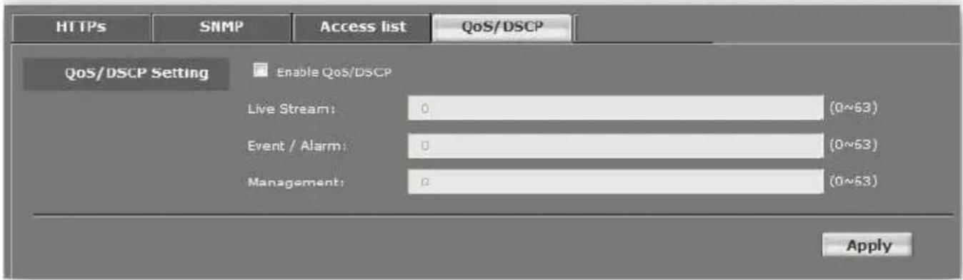
System > Advance > QoS/DSCP
QoS/DSCP (Quality of Server/Differentiated Services Code-point) specifies a simple mechanism for classifying and managing network traffic and provide QoS on IP networks. DSCP is a 6-bit in the IP header for packet classification purpose. The number 0\~63 for Live Stream, Event / Alarm, and Management represent the ratio that the bandwidth is divided. For example, if you set5, 10, and 20 for the three items, then the bandwidth of the three item is 5:10:20. There is no difference between setting "0, 0, 0" or "63, 63, 63" because under these two settings the three items will get equal bandwidth (1/3).
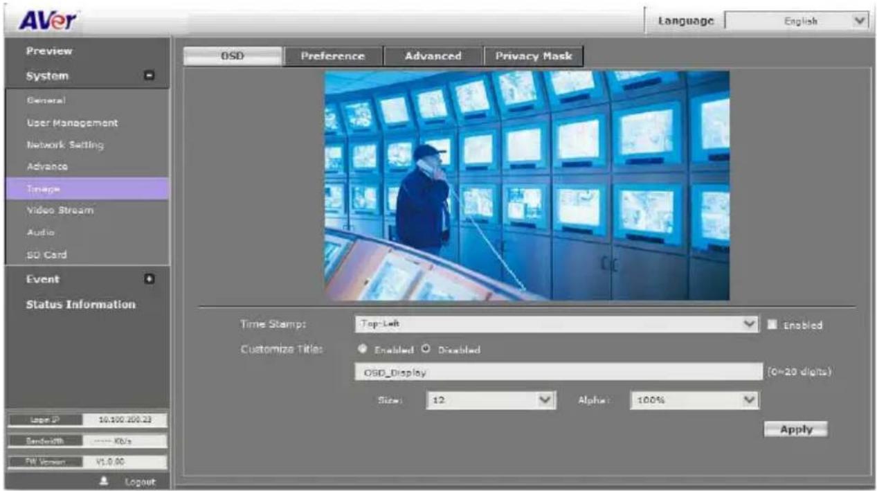
System > Image
Admin and operator levels can adjust the Image setting. There are 5 tabs: OSD, Preference, Exposure, Advanced, and Privacy Mask
System > Image> OSD
In OSD tab, you can enable/disable overlaying time stamp and text title. After completing the setting, click Save to apply the new setting and Cancel to keep the new setting.
■ Time Stamp: Mark Enable check box and select a position where date and time stamp / text to display on video screen.
■ Customize Title: Click Enabled can adjust the OSD contents which are including Size and Alpha of text.
System > Image > Preference
In Preference tab, you can tune the IP camera white balance, change the video orientation, and adjust the brightness and contrast.
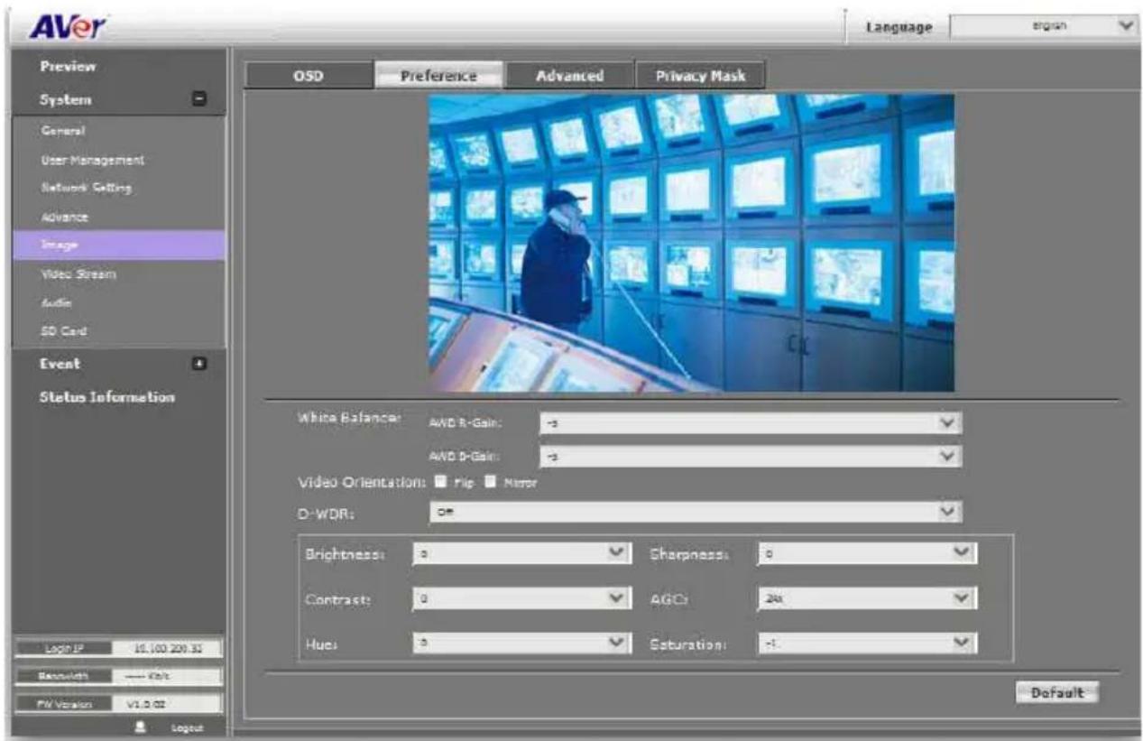
■ White Balance: Adjust white balance value.
■ Video Orientation: To Flip or Mirror the video on screen.
D-WDR: This function is able to reduce the contrast in the view to avoid the dark zones resulting from over and under exposure.
■ Adjust "Brightness", "Contrast", "Hue", "Saturation" to get clear video.
System > Image> Advanced
Click Default button will back to factory default setting.
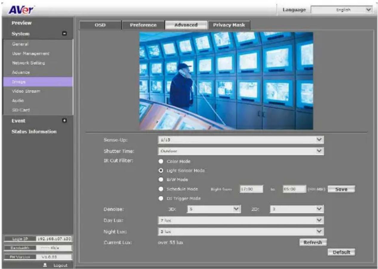
■ Sense-UP: The main purpose of sense-up is to provide a camera technology that does not rely on artificial light to see in very low light conditions. By The shutter stays open longer, allowing more light into the camera and seeing better in low light. This setting altogether when there is a moving object in the image and the faster the object moves, the worse the image appears (blurriness).
■ Shutter Time: Adjust the shutter time level to get the best image quality.
■ IR Cut Filter: Select the IR cut filter mode – Color Mode, Light Sensor Mode, B/W Mode, Schedule Mode, or DI Trigger Mode. When you choose "Light Sensor Mode", the image will be turned to black and white at night in order to keep clear. To set light sensor mode, appoint a lux standard of switching D/N here. Current lux value is provided for reference. Under "Times Mode" the switch time of Color / Black and white is according to the given time. You can also control it by choosing "Color" or "B/W".
■ Denoise: This function is able to filter the noise and blur from the image and show a clearer view. "3D" and "2D" are two different de-noising approaches. 3D denoise analyzes successive pictures to detect the noise places while 2D denoise analyzes only single picture.
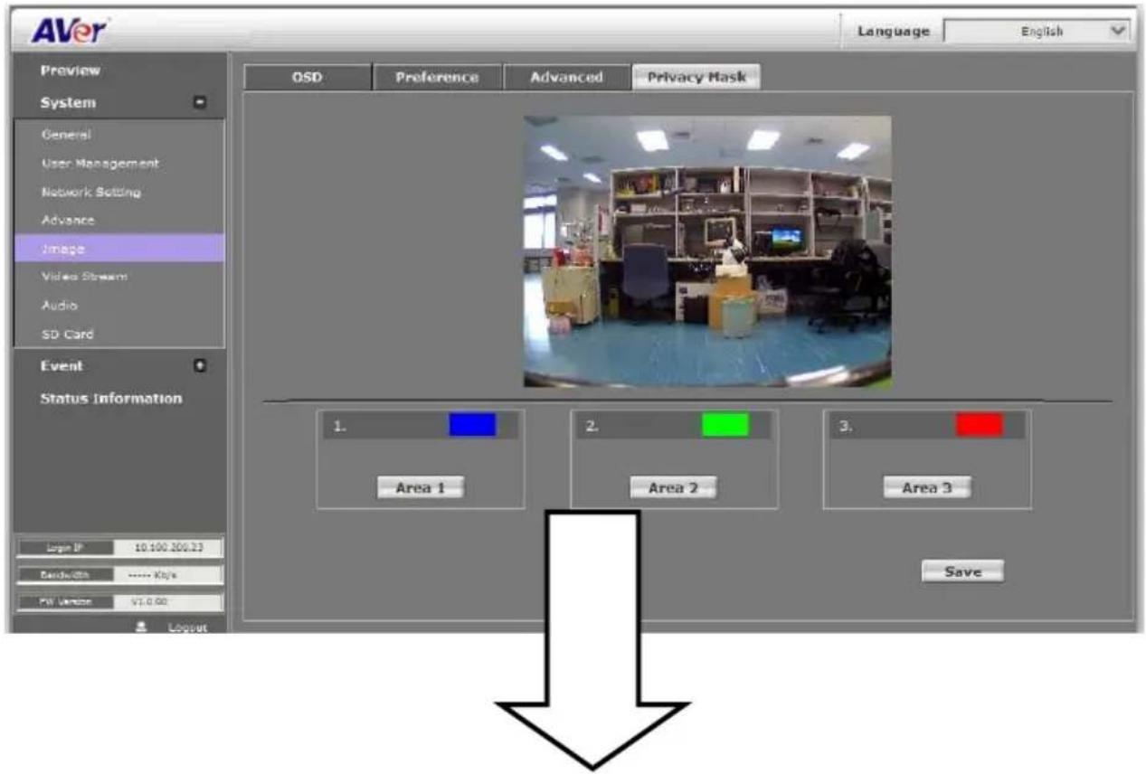
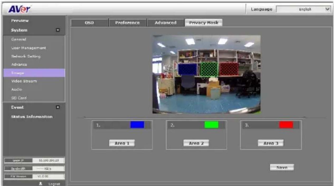
System > Image> Privacy Mask
For the security purpose, there are three areas can be setup for privacy mask. Click Area #(Area 1, Area 2, Area 3) button first and drag a area on the image screen. Then, click Save button to save the setting.
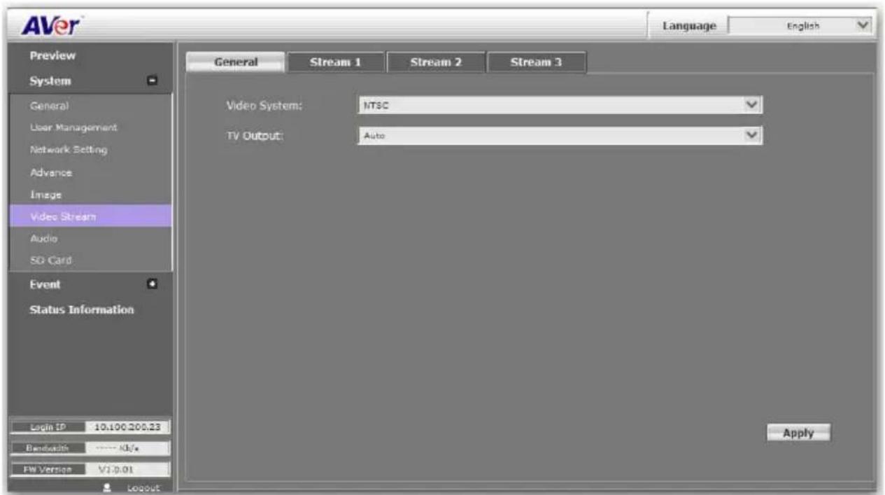
System > Video Stream > General
■ Input Resolution: Select the video resolution that is the maximum resolution supported in Stream 1 and Stream 2.
■ Video System: Select the video format.
■ TV Output: Select the video format of TV Output. (depending on different models)
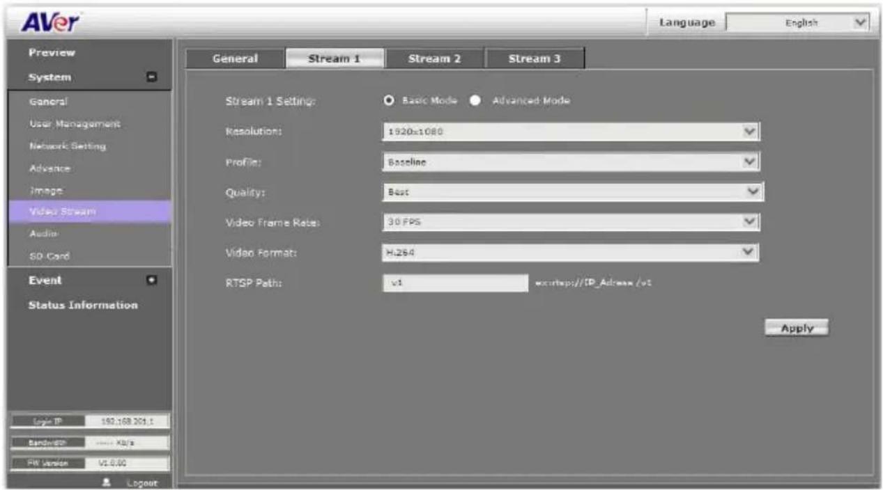
System > Video Stream > Stream1
Basic Mode
Click Apply to save the configuration.
- Resolution: There are 5 resolutions can be chosen -- 1920x1080, 1280x720, 640x480, 320x240, 176x144.
- Profile: Profiles are different compression way of H.264. High profile provides better coding efficiency. Note that some devises do not support every profile. For example, iPhone4 only supports Main profile.
- Quality: There are 5 levels to adjust – Best, High, Standard, Medium, and Low. The higher the quality is, the bigger the file size is. Also not good for internet transmitting.
- Video Frame Rate: The video refreshing rate per second.
- Video Format: H.264 or JPEG.
- RTSP Path: It's a URL address.
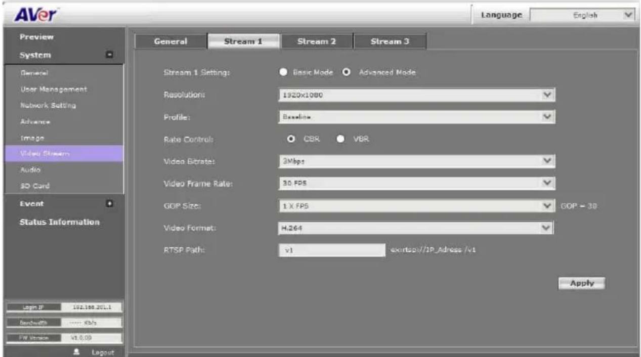
■ Advanced Mode
Click Apply to save the configuration.
- Resolution: There are 5 resolutions can be chosen -- 1920x1080, 1280x720, 640x480, 320x240, 176x144.
- Profile: Profiles are different compression way of H.264. High profile provides better coding efficiency. Note that some devises do not support every profile. For example, iPhone4 only supports Main profile.
- Rate Control: There are CBR (Constant Bit Rate) and VBR (Variable Bit Rate) to use. ✓ CBR: 32Kbps\~8Mbps (the higher the CBR is, the better the video quality is).
√ VBR: 1(Low) \~10(High) – Compression rate, the higher the compression rate, the better the picture quality is; vise versa. The balance between VBR and network bandwidth will affect picture quality. Please carefully select the VBR rate to avoid picture breaking up or lagging.
- Video Frame Rate: The video refreshing rate per second.
- GOP Size: It means "Group of Pictures".
- Video Format: H.264 or JPEG
- RTSP Path: It's a URL address
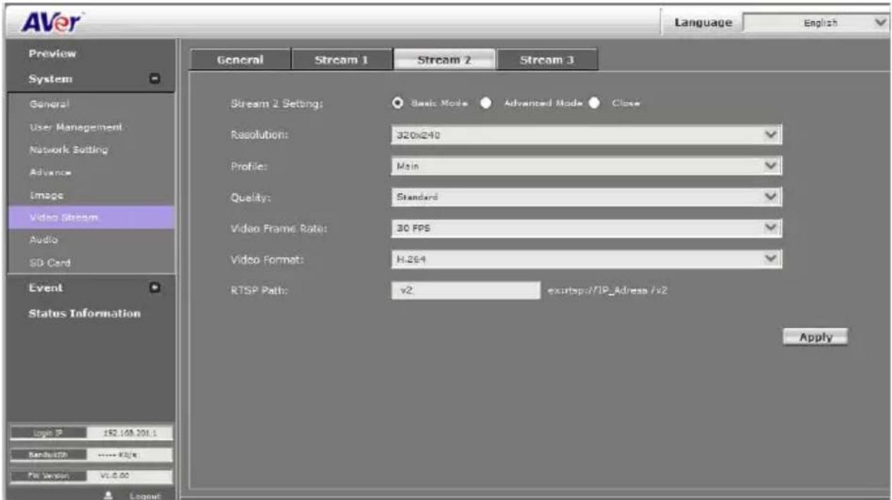
System > Video Stream > Stream2
Basic Mode
Click Apply to save the configuration.
- Resolution: There are 5 resolutions can select -- 1920x1080, 1280x720, 640x480, 320x240, 176x144.
- Profile: Profiles are different compression way of H.264. High profile provides better coding efficiency. Note that some devises do not support every profile. For example, iPhone4 only supports Main profile.
- Quality: There are 5 levels to adjust – Best, High. Standard, Medium, and Low. The higher the quality is, the bigger the file size is. Also not good for internet transmitting
- Video Frame Rate: The video refreshing rate per second.
- Video Format: H.264 or JPEG
- RTSP Path: It's a URL address
■ Advanced Mode
Click Apply to save the configuration.
- Resolution: There are 5 resolutions can select -- 1920x1080, 1280x720, 640x480, 320x240, 176x144.
- Profile: Profiles are different compression way of H.264. High profile provides better coding efficiency. Note that some devises do not support every profile. For example, iPhone4 only supports Main profile
- Rate Controls: CBR or VBR
- Video Bitrate: Select the bitrate of video.
- Video Frame Rate: The video refreshing rate per second.
- Video Format: H.264 or JPEG.
- RTSP Path: It's a URL address
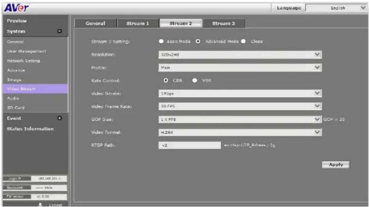
■ Close: To close the stream 2. Click Apply to save the configuration.
System > Video Stream > Stream3
3GPP Streaming is designed for mobile viewing.
Stream 3 Setting: Enable or Disable 3GPP Streaming.
■ 3GPP Path: It's a URL address.
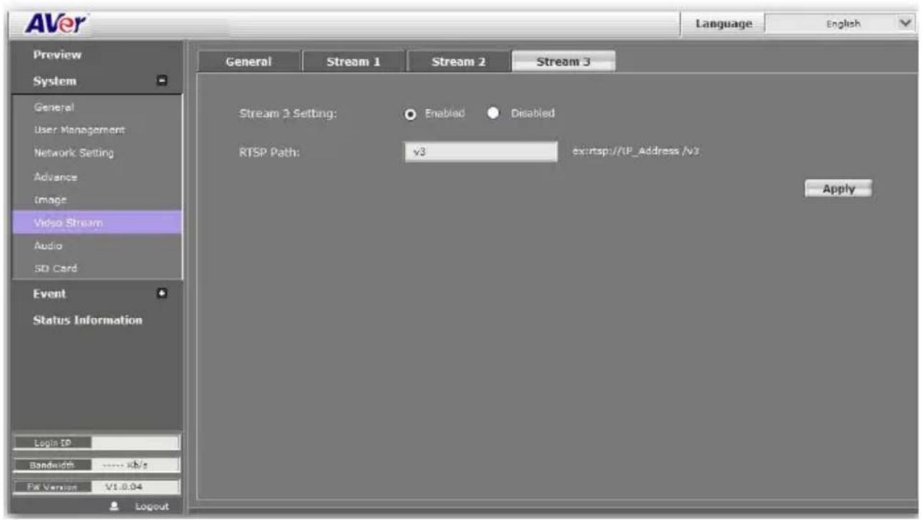
[Note]
- 3GPP mode video spec: 320x240 resolutions, 15FPS, MPEG4 format. (Audio: AMR)
- To get the best mobile viewing quality, please download AVeriViewer (AndroidViewer) from the Apple App store or Google Play. iViewer takes video from Stream 1 or Stream 2, not from 3GPP streaming.
System > Audio
IP camera supports 2-way audio (mono). User can send audio from IP camera built-in MIC (depending on different models) to remote site; User can also send audio from remote site to IP camera's external speaker.
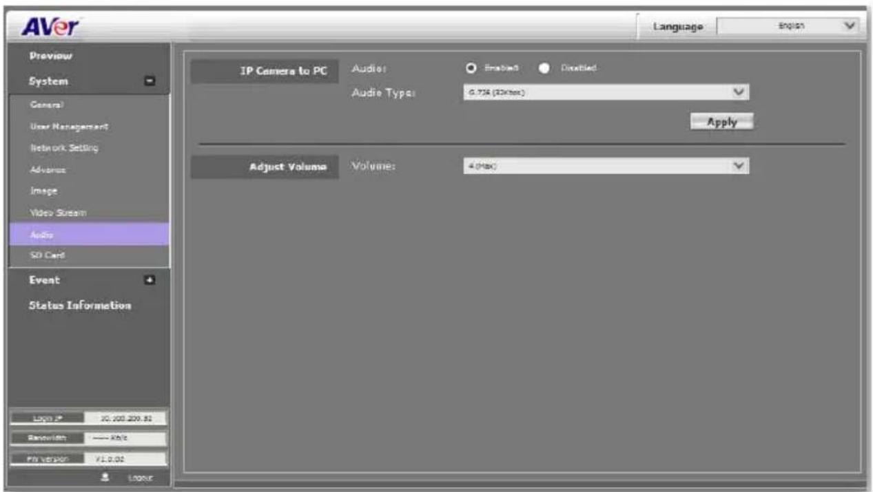
a. IP camera to PC: select "Enable" to start this function.
b. In live video screen, click button to start chatting. Press again to mute. Click button to turn on or off the speaker of PC.
[Note] The Audio will not be smooth when enable SD/SDHC card recording function simultaneously.
System > SD Card
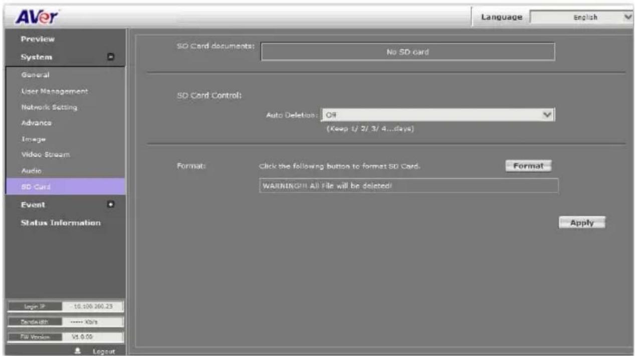
Please insert microSD/SDHC card before use it. Make sure pushing microSD/SDHC card into the slot completely.
[Note]The use of the microSD/SDHC card will affect the operation of the IP camera slightly, such as affecting the frame rate of the video.
Event > Arrangement > Motion
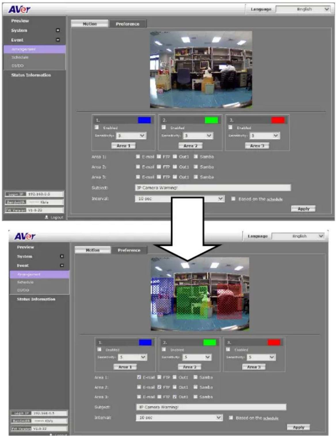
Motion Detection: IP camera allows 3 areas motion detection. When motion is triggered, it can send the video to some specific mail addresses, transmit the video to remote ftp server, trigger the relay, and save video to local SD/SDHC card. To set up the motion area 1, click "Area 1" button. Using mouse to drag and draw the area. The same operation for area 2 and 3. (The higher the sensitivity value is, the more sensitive to trigger event.)
Event > Arrangement > Preference
Record File:
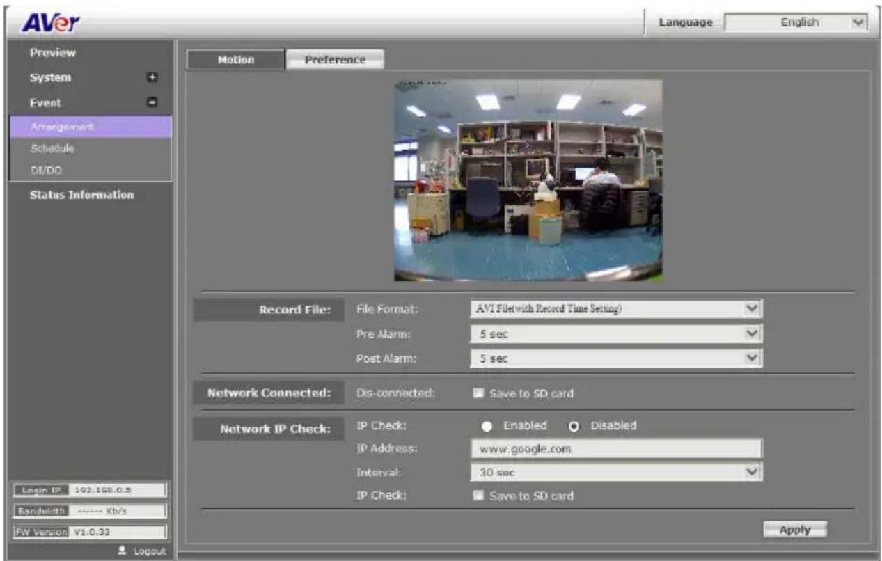
➢ File Format: IP camera allows 3 different types of recording file to change its record size. When motion/alarm is triggered, there are 3 different types of record mode.
- AVI File (With Record File Setting)
- JPEG Files (With Record File Setting), only with MJPEG compression format.
- Single JPEG (Single File with Interval Setting) (JPEG photo).
Pre Alarm and Post Alarm: Setups for video start and end time when motion detected, I/O, or other devices got triggered.
[Note] Pre/Post Alarm record time is base on record time setting and IP camera built-in Ram memory. Limited by IP camera built-in Ram Memory, When information is too much or video quality set too high, it will cause recording frame drop or decrease on post alarm recording time.
■ Network Connected: When the network is down, it will save the video to local SD/SDHC card. [Note] This function is only enabled in wire connection.
■ Network IP check: When the connection is down, it records the video to SD/SDHC card. Make sure the video recording is continuous. To use this function, key in the IP address of the PC which has recording software installed. Enable the function of "Save to SD card", then click "Apply". [Note] The interval of two video files on SD/SDHC card is fixed with 30 seconds.
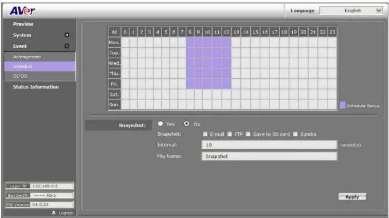
Event > Schedule
■ Schedule: After complete the schedule setup, the camera data will be recorded according to the schedule setup.
■ Snapshot: After enable the snapshot function; user can select the storage position of snapshot file, the Interval time of snapshot and the reserved File Name of snapshot.
Event > DI/DO
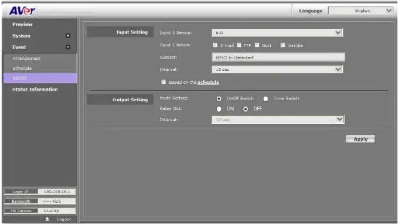
IP camera supports 1 input/1 output (depending on different models). When input is triggered, it can send the video to some specific mail addresses, transmit the video to remote ftp server, trigger the relay, and save video to local SD/SDHC card.
CAUTION!!
Please connect to propriety relay box to reduce the risk of electric shock & damaged.
Input Setting:
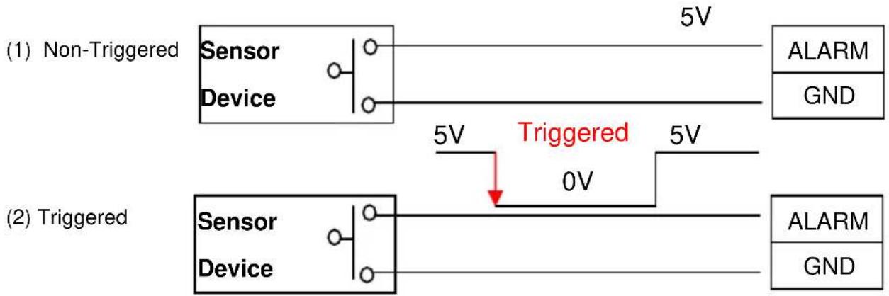
Input 1 sensor: This is to set the relay status while sensor is not yet triggered.
Input 1 action: Send the triggered video clips or photos to the selected method.
Subject: This is the subject while sending files via e-mail.
Output Setting:
Mode setting:
OnOff Switch: Relay status is based on sensor triggered times.
Time Switch: To restore the original relay status after the interval time.
[Note]GPIO pin define please refer to the part of Front / Back plane & I/O port pin assignment.
| Ground (G) | ALARM INPUT:Normal: 5V (The voltage differential from ALM_IN pin & Ground)Active: 0V (Short the pin of ALM_IN and Ground pin) |
| DI | |
| DO | RELAY OUTPUT:MAX: 50 mA, DV 5V |
| Ground(G) |
Status Information
Click Apply button to save the configuration.
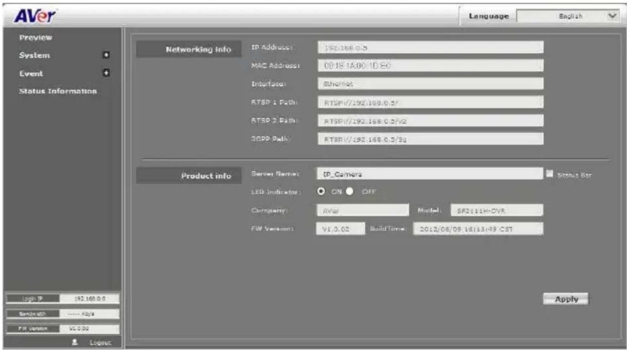
■ Networking Info: Displays network information of the IP camera.
■ Product Info:
Server Name: Assigns a name to the IP camera and the name shows on the IP Installer. Also, displays the related information of the IP camera. Mark Status Bar to display the Server Name of IP camera on preview interface.
LED indicator: To disable or enable the LED indicator on the IP camera. Only SF2111H-BR/DR/DVR has this function
Network Configuration
Configuration 1
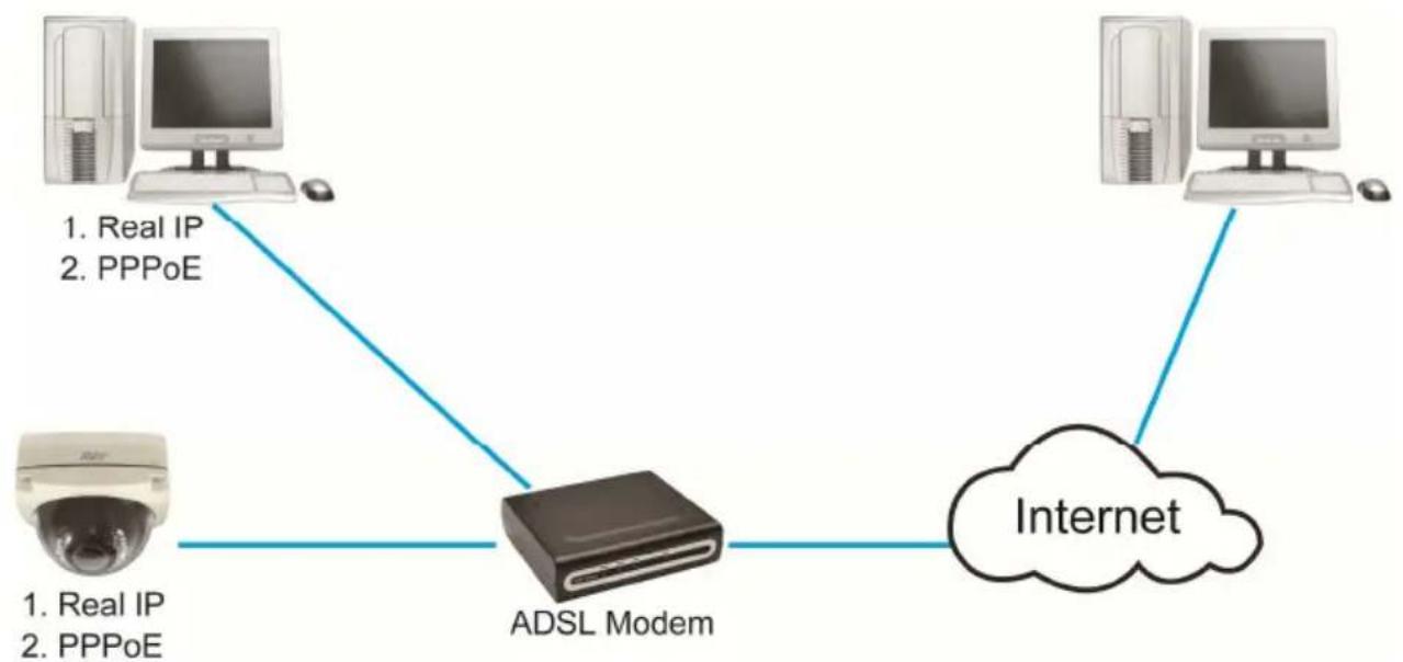
flowchart
graph TD
    A["Real IP"] -->|1. Real IP\n2. PPPoE| B["ADSL Modem"]
    C["Real IP"] -->|1. Real IP\n2. PPPoE| B
    D["Internet"] --> B
    B --> E["Computer"]
a. Internet Access: ADSL or Cable Modem
b. IP address: More than one real IP
c. IP camera and PC connect to the internet
d. For fixed real IP, set up the IP into IP camera and PC. For dynamic IP, start PPPoE.
Configuration 2
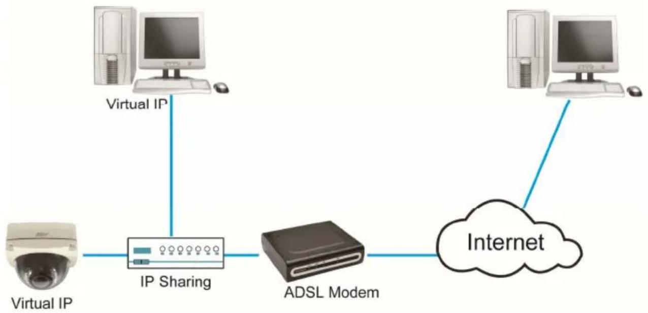
flowchart
graph LR
    A["Virtual IP"] --> B["IP Sharing"]
    C["Virtual IP"] --> B
    B --> D["ADSL Modem"]
    D --> E["Internet"]
    F["Internet"] --> E
a. Internet Access : ADSL or Cable Modem
b. IP address : one real IP
c. IPcamera and PC connect to the internet
d. Device needed : IP sharing
e. Use virtual IP, set up port forwarding in IP sharing.(Please refer to Network Setting→Other 1→UPnP Port Forwarding)
Factory Default
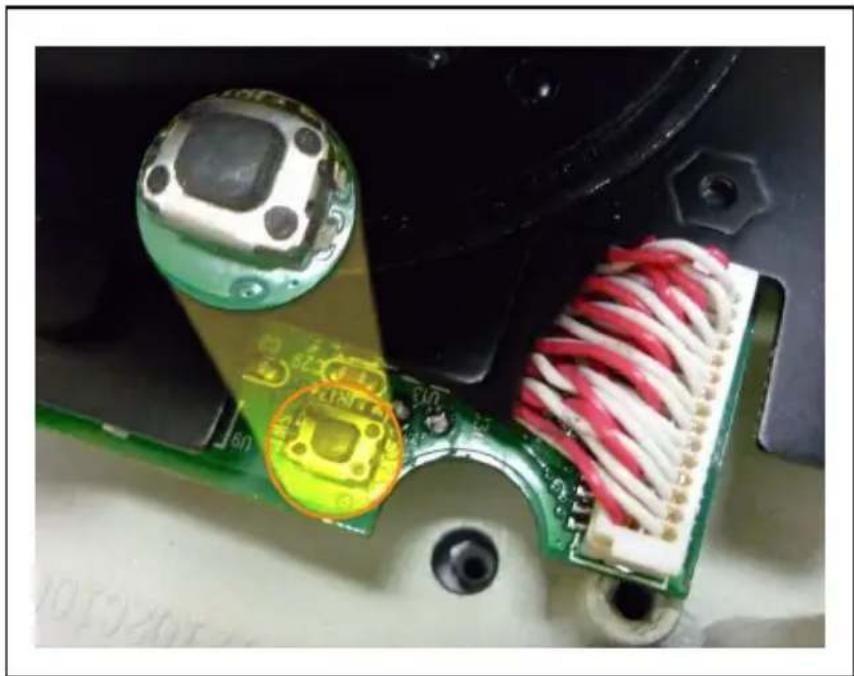
- To recover the default IP address and password, please follow the following steps.
- Remove power and Ethernet cable, press and hold the button for 10 sec. Please refer to the picture below.
natural_image
Close-up of a circuit board with electronic components and wiring, no visible text or symbols- Connect power and Ethernet cable to the camera again. Power on the camera. Don't release the button during the system booting.
- It will take around 30 seconds to boot the camera.
- Release the button when camera finishes proceed.
- Re-login the camera using the default IP (http://192.168.1.200) or DHCP, and user name (admin), password (admin).
Troubleshooting
Here are some useful tips on how to solve some common problems.
Problem Solution
| I forgot the account and password for SF2111H-DVR. How can I go back to default setting? | Please refer to the manual of “ Factory Default setting” description. |
| I can’t find a way to force day mode and night mode. Is this possible and how. | We don't provide this function due to the limitation of hardware. |
| I recorded video file in H.264 file format but failed to playback on Media Player (V.9). | Default Windows Media Player doesn’t have H.264 decoder so that you can’t playback the file successfully. Please install K-Lite program in advance or install KMPlayer or VLC program to playback the video file. You can search those free programs on Internet. |
Appendix
SF2111H-DVR is compliant with microSD/SDHC card and to ensure recording quality, and please use memory cards over 2G and Class 4 above (Max. 32G)
| MicroSD/SDHC card SD/SDHC | |
| Transcend SDHC class4 16GB Transcend SDHC Class 4 16GB | |
| Transcend SD class4 16GB Transcend SD Class 4 16GB | |
| Transcend SDHC class4 32GB Transcend SDHC Class 4 32GB | |
| Transcend SD class4 32GB Transcend SD Class 4 32GB | |
| Transcend SD class6 4GB Transcend SD Class 6 4GB | |
| Transcend SDHC class6 4GB Transcend SDHC Class 6 4GB | |
| Transcend SD class6 8GB Transcend SD Class 6 8GB | |
| Transcend SDHC class6 8GB Transcend SDHC Class 6 8GB | |
| Transcend SD class6 16GB Transcend SD Class 6 16GB | |
| Transcend SDHC class6 16GB Transcend SDHC Class 6 16GB | |
| Transcend SDHC class10 4GB Transcend SDHC Class10 4GB | |
| Transcend SDHC class10 8GB Transcend SDHC Class10 8GB | |
| Transcend SDHC class10 16GB Transcend SDHC Class10 16GB | |
| SanDisk SDHC class4 4GB SanDisk SDHC Class 4 4GB | |
| SanDisk SDHC class4 8GB SanDisk SDHC Class 4 8GB | |
| SanDisk SDHC class4 16GB SanDisk SDHC Class 4 16GB | |
| SanDisk SDHC class4 32GB SanDisk SDHC Class 4 32GB |
■ SF2111H-R/SF2111H-D: SDHC/SD card
■ SF2111H-B/SF2111H-DVR: microSDHC/SD card
COPYRIGHT
© 2012 AVer Information Inc. All rights reserved.
All rights of this object belong to AVer Information Inc. Reproduced or transmitted in any form, or by any means without the prior written permission of AVer Information Inc. is prohibited. AVer Information Inc. reserves the rights to modify its products, including their specifications and any other information stated herein without notice. The official printout of any information shall prevail should there be any discrepancy between the information contained herein and the information contained in that printout. "AVer" is a trademark owned by AVer Information Inc. Other trademarks used herein for description purpose only belong to each of their companies.
NOTICE
SPECIFICATIONS ARE SUBJECT TO CHANGE WITHOUT PRIOR NOTICE. THE INFORMATION CONTAINED HEREIN IS TO BE CONSIDERED FOR REFERENCE ONLY.
WARNING
TO REDUCE RISK OF FIRE OR ELECTRIC SHOCK, DO NOT EXPOSE THIS APPLIANCE TO RAIN OR MOISTURE. WARRANTY VOID FOR ANY UNAUTHORIZED PRODUCT MODIFICATION.
THE MARK OF CROSSED-OUT WHEELED BIN INDICATES THAT THIS PRODUCT MUST NOT BE DISPOSED OF WITH YOUR OTHER HOUSEHOLD WASTE. INSTEAD, YOU NEED TO DISPOSE OF THE WASTE EQUIPMENT BY HANDING IT OVER TO A DESIGNATED COLLECTION POINT FOR THE RECYCLING OF WASTE ELECTRICAL AND ELECTRONIC EQUIPMENT. FOR MORE INFORMATION ABOUT WHERE TO DROP OFF YOUR WASTE EQUIPMENT FOR RECYCLING, PLEASE CONTACT YOUR HOUSEHOLD WASTE DISPOSAL SERVICE OR THE SHOP WHERE YOU PURCHASED THE PRODUCT.
Limited Warranty
AVer Information, Inc. (“AVer”) warrants that the applicable product (“Product”) substantially conforms to AVer’s documentation for the product and that its manufacture and components are free of defects in material and workmanship under normal use. “You” as used in this agreement means you individually or the business entity on whose behalf you use or install the product, as applicable. This limited warranty extends only to You as the original purchaser. Except for the foregoing, the Product is provided “AS IS.” In no event does AVer warrant that You will be able to operate the Product without problems or interruptions, or that the Product is suitable for your purposes. Your exclusive remedy and the entire liability of AVer under this paragraph shall be, at AVer’s option, the repair or replacement of the Product with the same or a comparable product. This warranty does not apply to (a) any Product on which the serial number has been defaced, modified, or removed, or (b) cartons, cases, batteries, cabinets, tapes, or accessories used with this product. This warranty does not apply to any Product that has suffered damage, deterioration or malfunction due to (a) accident, abuse, misuse, neglect, fire, water, lightning, or other acts of nature, commercial or industrial use, unauthorized product modification or failure to follow instructions included with the Product, (b) misapplication of service by someone other than the manufacturer’s representative, (c) any shipment damages (such claims must be made with the carrier), or (d) any other causes that do not relate to a Product defect. The Warranty Period of any repaired or replaced Product shall be the longer of (a) the original Warranty Period or (b) thirty (30) days from the date of delivery of the repaired or replaced product.
Limitations of Warranty
AVer makes no warranties to any third party. You are responsible for all claims, damages, settlements, expenses, and attorneys' fees with respect to claims made against You as a result of Your use or misuse of the Product. This warranty applies only if the Product is installed, operated, maintained, and used in accordance with AVer specifications. Specifically, the warranties do not extend to any failure caused by (i) accident, unusual physical, electrical, or electromagnetic stress, neglect or misuse, (ii) fluctuations in electrical power beyond AVer specifications, (iii) use of the Product with any accessories or options not furnished by AVer or its authorized agents, or (iv) installation, alteration, or repair of the Product by anyone other than AVer or its authorized agents.
Disclaimer of Warranty
EXCEPT AS EXPRESSLY PROVIDED OTHERWISE HEREIN AND TO THE MAXIMUM EXTENT PERMITTED BY APPLICABLE LAW, AVER DISCLAIMS ALL OTHER WARRANTIES WITH RESPECT TO THE PRODUCT, WHETHER EXPRESS, IMPLIED, STATUTORY OR OTHERWISE, INCLUDING WITHOUT LIMITATION, SATISFACTORY QUALITY, COURSE OF DEALING, TRADE USAGE OR PRACTICE OR THE IMPLIED WARRANTIES OF MERCHANTABILITY, FITNESS FOR A PARTICULAR PURPOSE OR NONINFRINGEMENT OF THIRD PARTY RIGHTS.
Limitation of Liability
IN NO EVENT SHALL AVER BE LIABLE FOR INDIRECT, INCIDENTAL, SPECIAL, EXEMPLARY, PUNITIVE, OR CONSEQUENTIAL DAMAGES OF ANY NATURE INCLUDING, BUT NOT LIMITED TO, LOSS OF PROFITS, DATA, REVENUE, PRODUCTION, OR USE, BUSINESS INTERRUPTION, OR PROCUREMENT OF SUBSTITUTE GOODS OR SERVICES ARISING OUT OF OR IN CONNECTION WITH THIS LIMITED WARRANTY, OR THE USE OR PERFORMANCE OF ANY PRODUCT, WHETHER BASED ON CONTRACT OR TORT, INCLUDING NEGLIGENCE, OR ANY OTHER LEGAL THEORY, EVEN IF AVER HAS ADVISED OF THE POSSIBILITY OF SUCH DAMAGES. AVER'S TOTAL, AGGREGATE LIABILITY FOR DAMAGES OF ANY NATURE, REGARDLESS OF FORM OF ACTION, SHALL IN NO EVENT EXCEED THE AMOUNT PAID BY YOU TO AVER FOR THE SPECIFIC PRODUCT UPON WHICH LIABILITY IS BASED.
Governing Law and Your Rights
This warranty gives you specific legal rights; You may also have other rights granted under state law. These rights vary from state to state.
- AVer SF2111H-DVR
- Table of Contents
- PREFACE ....1
- PRODUCT SPECIFICATIONS....1
- PACKAGE CONTENTS......4
- PRODUCT INSTALLATION....5
- USING THE IP CAMERA BROWSER INTERFACE 22
- Preface
- Product Specifications
- Product Installation
- Monitor Setting
- Hardware Installation and I/O Pin Assignment
- Installation Tips
- I/O Interface
- I/O Connection
- Power Over Ethernet (PoE)
- IP Assignment
- Finding IP Camera by using "NXU Lite recording software"
- Click "Setup" button.
- Click "Add IPCam" button.
- Select "IP Camera" item.
- Finding IP Camera by using "IP installer"
- IP Installer configuration:
- Using DHCP Server/Router Network
- Using NON-DHCP Server/Router Network
- [Example]
- The same Subnet:
- Different Subnets:
- To Change PC IP Address:
- IP camera IP addresses:
- Install ActiveX Control
- 5
- Using the IP Camera Browser Interface
- Preview
- System > General
- System > General > Maintenance
- Name Function
- Firmware Upgrade
- To Upgrade the IP Camera Firmware
- System > General > Date & Time
- Setting Method
- System > User Management
- System > User Management > Account
- User Type Access Rights
- ■ Anonymous User Login
- [Note]
- System > Network Setting > Setting
- System > Network Setting > Sever
- System > Network Setting > DDNS
- Status
- - Common warning message:
- - Warning message from different service provider:
- Server Provider : dyndns.org
- Server Provider : ddns.camddns.com(TW)
- Server provider : ddns.ipddn.com(HK)
- Server provider : www.3322.org.
- System > Network Setting > Other 1
- System > Network Setting > Other 2
- Multicast operation example:
- Step 1:
- Step 4:
- [Notice]
- System > Advance > HTTPS
- System > Advance > SNMP
- System > Advance > Access list
- System > Advance > QoS/DSCP
- System > Image
- System > Image> OSD
- System > Image > Preference
- System > Image> Advanced
- System > Image> Privacy Mask
- System > Video Stream > General
- System > Video Stream > Stream1
- Basic Mode
- ■ Advanced Mode
- System > Video Stream > Stream2
- System > Video Stream > Stream3
- System > Audio
- System > SD Card
- Event > Arrangement > Motion
- Event > Arrangement > Preference
- Record File:
- Event > Schedule
- Event > DI/DO
- CAUTION!!
- Input Setting:
- Output Setting:
- Mode setting:
- Status Information
- Network Configuration
- Configuration 1
- Configuration 2
- Factory Default
- Troubleshooting
- Appendix
- COPYRIGHT
- NOTICE
- WARNING
- Limited Warranty
- Limitations of Warranty
- Disclaimer of Warranty
- Limitation of Liability
- Governing Law and Your Rights
Brand : AVer
Model : SF2111H-DR
Category : Security Camera