TR315N - Security Camera AVer - Free user manual and instructions
Find the device manual for free TR315N AVer in PDF.


| Product Type | AI Auto Tracking PTZ Camera |
| Brand | AVer |
| Model | TR315N |
| Dimensions (W x H x D) | 156.5 mm x 180 mm x 191.5 mm |
| Weight | Approx. 2.5 kg (5.5 lbs) |
| Power Supply | PoE+ (IEEE 802.3at) or DC 12V |
| Optical Zoom | 12X |
| Digital Zoom | Up to 12X |
| Pan Range | 170° |
| Tilt Range | -30° to +90° |
| Video Outputs | HDMI, 3G-SDI (except H models), USB 3.0 (Type-B) |
| Audio Input | Line in / Mic in (3.5mm) |
| Network | 10/100 Ethernet, PoE+, RTSP, RTMP, SRT, NDI | HX3 (license required) |
| Control Interfaces | RS-232, RS-422, VISCA over IP, Pelco P/D |
| Tracking Modes | Presenter, Zone, Hybrid, Click Track |
| Gesture Control | Yes (Tracking and PTZ gestures) |
| Preset Positions | Up to 256 |
| LED Indicators | Power, Tracking, Gesture recognition |
| Security | Kensington lock, HTTPS, 802.1x, user authentication |
| Mounting | Ceiling mount (included), optional wall mount |
| Operating Temperature | 0°C to 40°C (32°F to 104°F) |
| Included Accessories | Remote control, mounting bracket, power adapter, RS-232 cable, cable fixing plate |
| Maintenance | Clean lens with soft dry cloth; keep away from moisture |
| Spare Parts / Repairability | Contact AVer support for service; no user-serviceable parts inside |
Frequently Asked Questions - TR315N AVer
User questions about TR315N AVer
0 question about this device. Answer the ones you know or ask your own.
Ask a new question about this device
Download the instructions for your Security Camera in PDF format for free! Find your manual TR315N - AVer and take your electronic device back in hand. On this page are published all the documents necessary for the use of your device. TR315N by AVer.
USER MANUAL TR315N AVer
natural_image
Technical line drawing of a mechanical device with no visible text or symbols on the body or background.AI Auto Tracking PTZ Camera
— User Manual —
TR335 / TR335N / TR315 / TR315N / TR211 / TR311V3 / TR325 / TR325N
PTC310V3 / PTC310UV3 / PTC310UNV3 / PTC320UV3 /
PTC320UNV3 / PTC330UV3 / PTC330UNV3
Federal Communications Commission
NOTE: This equipment has been tested and found to comply with the limits for a Class A digital device, pursuant to part 15 of the FCC Rules. These limits are designed to provide reasonable protection against harmful interference when the equipment is operated in a commercial environment. This equipment generates, uses, and can radiate radiofrequency energy and, if not installed and used in accordance with the instruction manual, may cause harmful interference to radio communications. Operation of this equipment in a residential area is likely to cause harmful interference in which case the user will be required to correct the interference at his own expense.
FCC Caution: Any changes or modifications not expressly approved by the party responsible for compliance could void the user's authority to operate this equipment.
This device complies with part 15 of the FCC Rules.
Operation is subject to the following two conditions:
(1) This device may not cause harmful interference, and
(2) this device must accept any interference received, including interference that may cause undesired operation.
Warning
This is a class A product. In a domestic environment, this product may cause radio interference in which case the user may be required to take adequate measures.
Risk of Explosion if Battery is replaced by an Incorrect Type.
Dispose of Used Batteries According to the Instructions.
Remote Control Battery Safety Information
- Store batteries in a cool and dry place.
- Do not throw away used batteries in the trash. Properly dispose of used batteries through specially approved disposal methods.
- Remove the batteries if they are not in use for long periods of time. Battery leakage and corrosion can damage the remote control. Dispose of batteries safely and through approved disposal methods.
- Do not use old batteries with new batteries.
- Do not mix and use different types of batteries: alkaline, standard (carbon-zinc) or rechargeable (nickel-cadmium).
- Do not dispose of batteries in a fire.
- Do not attempt to short-circuit the battery terminals.
DISCLAIMER
No warranty or representation, either expressed or implied, is made with respect to the contents of this documentation, its quality, performance, merchantability, or fitness for a particular purpose. Information presented in this documentation has been carefully checked for reliability; however, no responsibility is assumed for inaccuracies. The information contained in this documentation is subject to change without notice.
In no event will AVer Information Inc. be liable for direct, indirect, special, incidental, or consequential damages arising out of the use or inability to use this product or documentation, even if advised of the possibility of such damages.
TRADEMARKS
“AVer” is a trademark owned by AVer Information Inc. Other trademarks used herein for description purpose only belong to each of their companies.
COPYRIGHT
© 2023 AVer Information Inc. All rights reserved. | August 25, 2023
All rights of this object belong to AVer Information Inc. Reproduced or transmitted in any form or by any means without the prior written permission of AVer Information Inc. is prohibited. All information or specifications are subject to change without prior notice.
NOTICE
Specifications Are Subject to Change without Prior Notice. The Information Contained Herein Is to Be Considered for Reference Only.
WARNING
■ To reduce the risk of fire or electric shock, do not expose this appliance to rain or moisture. Warranty will be void if any unauthorized modifications are done to the product.
■ Do not drop the camera or subject it to physical shock.
■ Use the correct power supply voltage to avoid the damaging camera.
■ Do not place the camera where the cord can be stepped on as this may result in fraying or damage to the lead or the plug.
■ Hold the bottom of the camera with both hands to move the camera. Do not grab the lens or lens holder to move the camera.
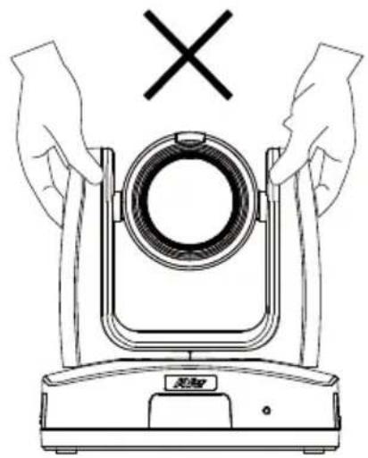
natural_image
Line drawing of hands holding a device with a circular component and a cross symbol above (no text or labels)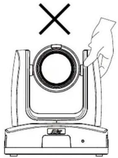
natural_image
Line drawing of a mechanical device with a hand adjusting its top component (no text or symbols)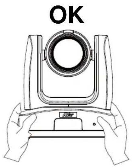
More Help
For FAQs, technical support, software and user manual download, please visit:
Headquarters
Download Center: https://www.aver.com/download-center Technical Support: https://www.aver.com/technical-support
USA Branch office
Download Center: https://www.averusa.com/pro-av/support/Technical Support: https://averusa.force.com/support/s/contactsupport
Europe Branch office
Download Center: https://www.avereurope.com/download-center Technical Support: https://www.avereurope.com/technical-support
Contact Information
Headquarters
AVer Information Inc.
https://www.aver.com
8F, No.157, Da-An Rd., Tucheng Dist., New Taipei City 23673, Taiwan
Tel: +886 (2) 2269 8535
USA Branch office
AVer Information Inc., Americas
https://www.averusa.com
668 Mission Ct., Fremont, CA 94539, USA
Tel: +1 (408) 263 3828
Toll-free: +1 (877) 528 7824
Technical support: support.usa@aver.com
Europe Branch office
AVer Information Europe B.V. https://www.avereurope.com Westblaak 134, 3012 KM, Rotterdam, The Netherlands Tel: +31 (0) 10 7600 550 Technical support: eu.rma@aver.com
Japan Branch Office
Vietnam Branch Office
Optional Accessories....3
Product Introduction .... 4
Overview....4
Dimensions....5
Pan and Tilt Angle 8
LED Indicators....9
Device Connection....9
PoE Connection....10
RS-232 and RS-422 Connection....11
Audio Input Connection....16
Video Output Connection ....17
Cable Fixing Plate Installation....18
Ceiling Mount Installation 19
Camera Installation....20
Remote Control 21
Set Up the Camera 23
OSD Menu....23
IP Address Setup....23
Static IP 23
DHCP 24
OSD Menu Tree....25
Camera....25
Video Output 28
Network 28
Advanced Setting 28
System 28
Web Setup....30
Access the Web Interface of the Camera 30
Access the Camera via AVer IPCam Utility 30
Accessing the Camera via AVer PTZ Management 32
Live View 33
Camera Control 33
Preset 35
Camera Settings....36
Exposure 36
Image Process ....37
Video & Audio 38
Network 40
Tracking Settings....45
Presenter Mode....47
Zone Mode 51
Hybrid Mode ....53
Gesture....55
NDI 57
System....59
Appendix....61
VISCA RS-232 Command Table 61
Visca over IP Settings 65
CGI Command....66
Pelco P Command....69
Pelco D Command 70
Package Contents
Package Contents
Camera Unit
Drilling Paper
Ceiling Mount Bracket (x2)
Quick Start Guide
Cable Fixing Plate

M2 x 4mm
Screw (x3)
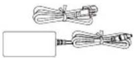
Power Adapter & Power Cord

1/4"-20 L=6.5mm Screw (x2)
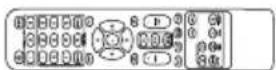
Remote Control

M3 x 6mm
Screw (x3)
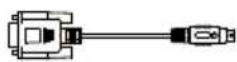
DIN8 to D-Sub9 Cable
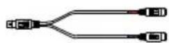
RS-232 In/Out
Y Cable
Cable Ties (x4)
*The power cord will vary depending on the standard power outlet of the country where it is sold.
Optional Accessories
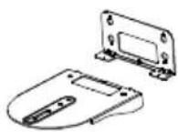
Wall Mount Bracket
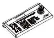
Camera Controller (CL01)
* For details on optional accessories, please consult with your local dealer.
Product Introduction
Overview
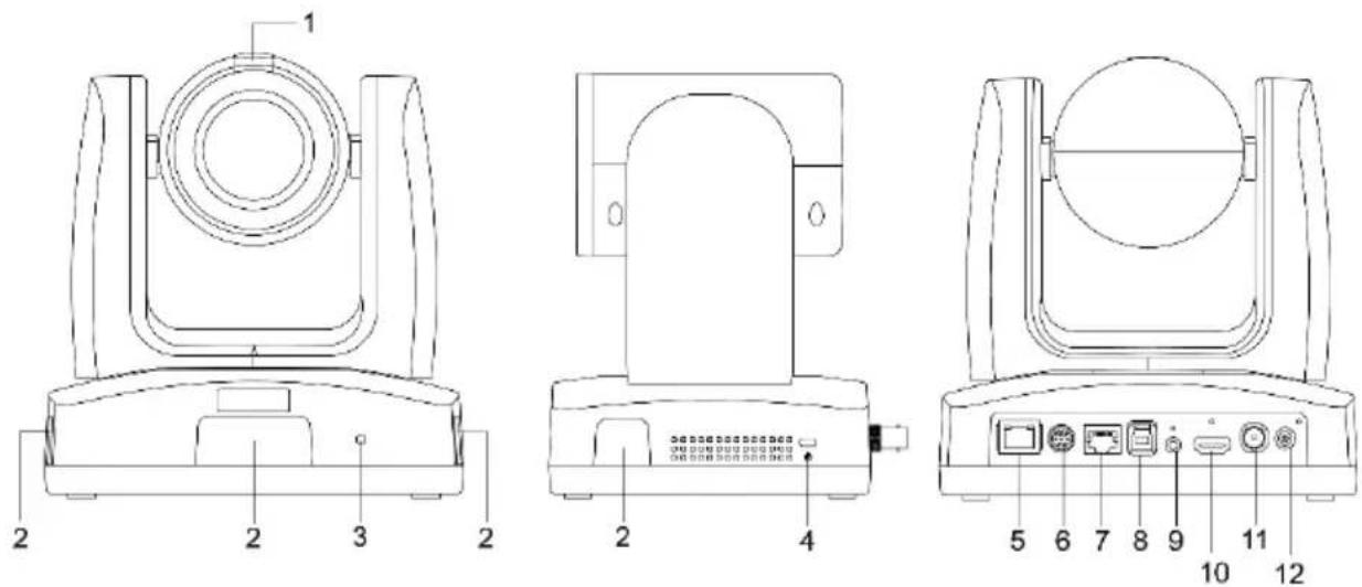
1 Tally Lamp
2 IR Sensor
3 LED Indicator
4 Kensington Lock
5 PoE+ IEEE 802.3AT
6 RS-232 Port
7 RS-422 Port
8 USB 3.0 Port (Type-B) DC 12V
9 Audio In*
10 HDMI Port
11 3G-SDI**
12 DC Power Jack
*Line input level: 1Vrms (max.).
*Mic input level: 50mVrms (max.); Supplied voltage: 2.5V.
**The model names with "H" do not have this feature.
Dimensions
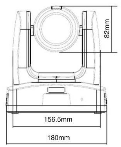
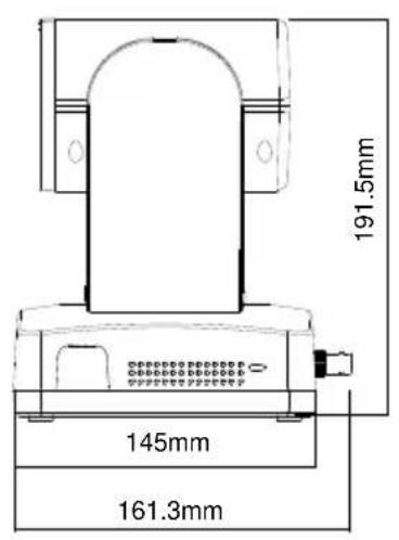
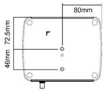
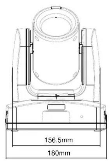
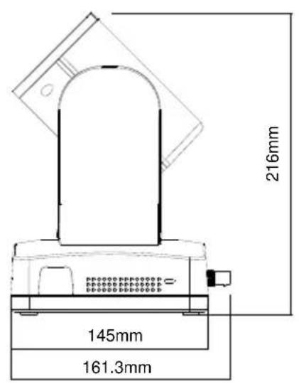
Ceiling Mount
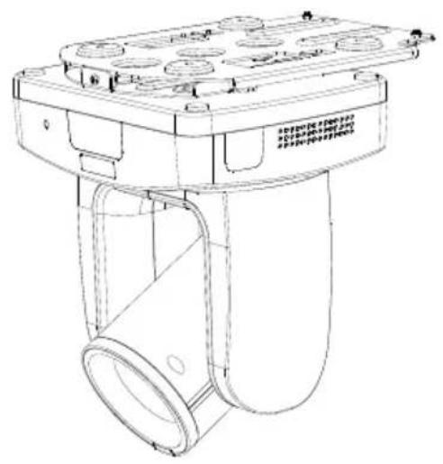
natural_image
Technical line drawing of a mechanical device with multiple circular components and a central cylindrical housing (no text or symbols)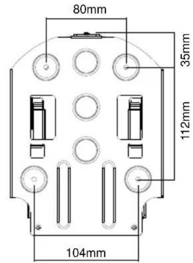
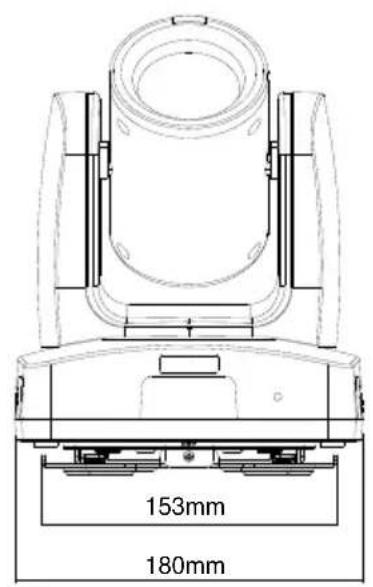
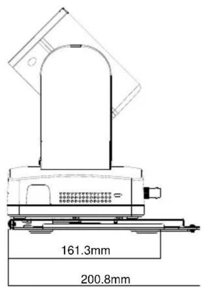
Wall Mount
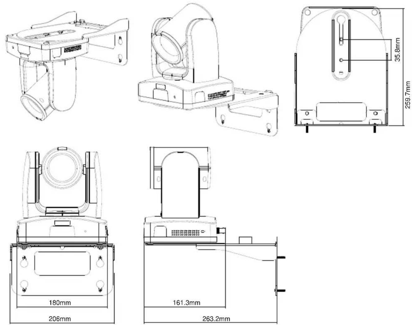
Pan and Tilt Angle
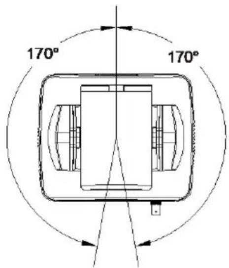
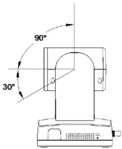
LED Indicators
| LED | Status |
| Flashing blue | Auto Tracking On |
| Solid blue | Normal |
| Flashing red | Firmware update |
| Solid orange | Standby |
| Flashing orange | Start-up |
| Flashing purple | Gesture recognition |
Device Connection
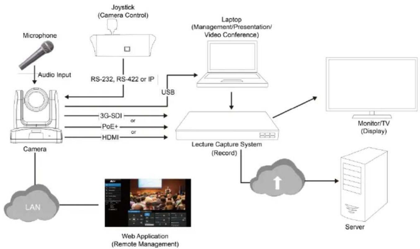
flowchart
graph TD
    A["Microphone"] -->|Audio Input| B["Camera"]
    B --> C["LAN"]
    C --> D["Web Application\n(Remote Management)"]
    D --> E["Lecture Capture System\n(Record)"]
    E --> F["Laptop\n(Management/Presentation/Video Conference)"]
    F --> G["Monitor/TV\n(Display)"]
    G --> H["Server"]
    H --> I["Cloud with Up arrow"]
    I --> E
    B --> J["3G-SDI or PoE+ or HDMI"]
    J --> K["USB"]
    K --> F
    style A fill:#f9f,stroke:#333
    style B fill:#ccf,stroke:#333
    style C fill:#cfc,stroke:#333
    style D fill:#fcc,stroke:#333
    style E fill:#cff,stroke:#333
    style F fill:#ffc,stroke:#333
    style G fill:#fcc,stroke:#333
    style H fill:#ccf,stroke:#333
    style I fill:#cfc,stroke:#333
    style J fill:#cfc,stroke:#333
    style K fill:#cfc,stroke:#333
    style_L["JS"] --> M["Robot"]
    N["JS"] --> O["Robot"]
    P["JS"] --> Q["Robot"]
    R["JS"] --> S["Robot"]
    T["JS"] --> U["Robot"]
    V["JS"] --> W["Robot"]
    X["JS"] --> Y["Robot"]
    Z["JS"] --> AA["Robot"]
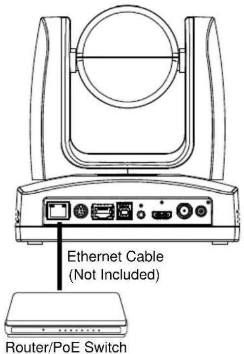
PoE Connection
Connect the camera to the router or switch through the PoE+ port.
[Note] Only support IEEE 802.3AT PoE+ standard.
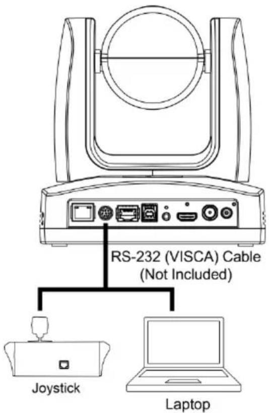
RS-232 and RS-422 Connection
Connect through the RS-232 or RS-422 for camera control.
- RS-232
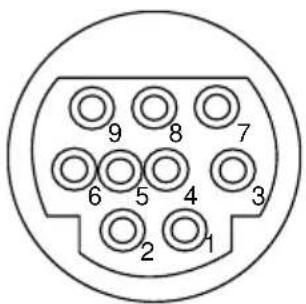
| Function | Mini DIN9 PIN # | I/O Type | Signal | Description |
| VISCA IN | 1 | Output | DTR | Data Terminal Ready |
| 2 | Input | DSR | Data Set Ready | |
| 3 | Output | TXD | Transmit Data | |
| 6 | Input | RXD | Receiver Data | |
| VISCA OUT | 7 | Output | DTR | Data Terminal Ready |
| 4 | Input | DSR | Data Set Ready | |
| 8 | Output | TXD | Transmit Data | |
| 9 | Input | RXD | Receiver Data | |
| 5 | Input | I/O | Detect DIN8/DIN9 | |
| --- | Shield | --- | GND | Ground |
flowchart
graph LR
    A["Mini DIN9"] --> B["Connect to AVer camera"]
    C["IN(Mini DIN8)"] --> D["Connect to controller or PC"]
    C --> E["Connect to next camera"]
    F["OUT(Mini DIN8)"] --> G["Connect to next camera"]
CIRCUITS:
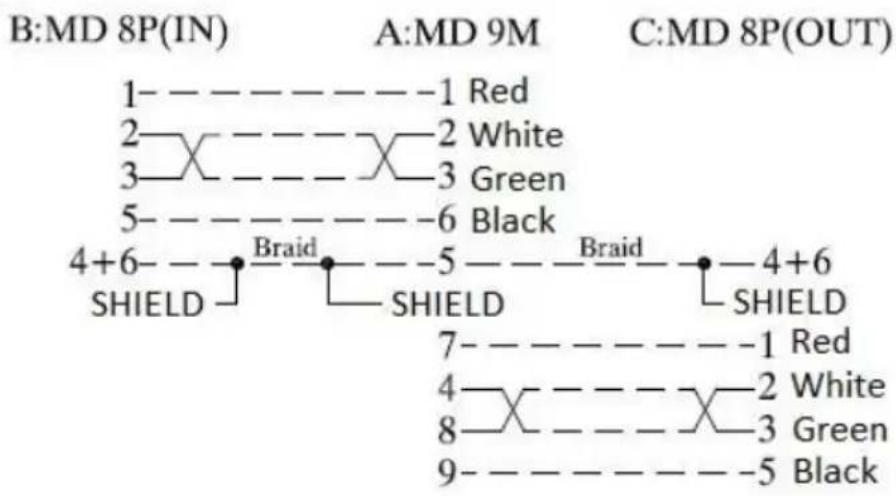
flowchart
graph TD
    A["1- - - - - - - - - - - - - - - - - - - - - - - - - - - - - - - - - - - - - - - - - - - - - - - - - - - - - - - - - - - - - - - - - - - - - - - - -"] --> B["2- X- - - - - X- 2 White"]
    B --> C["3- X- - - - X- 3 Green"]
    C --> D["5- - - - - - - - - - - - - - - - - - - - - - - - - - - - - - - - - - - - - - - - - - - - - - - - - - -"] --> E["4+6- Braid"]
    E --> F["SHIELD"]
    F --> G["SHIELD"]
    G --> H["4+6- Braid"]
    H --> I["SHIELD"]
    I --> J["SHIELD"]
    J --> K["7- - - - - - - - - - - - - - - - - - - - - - - - - 4 Red"]
    K --> L["4- X- - - - X- 2 White"]
    L --> M["8- X- X- 3 Green"]
    M --> N["9- X- X- 5 Black"]
Mini DIN8 Cable Pin Definition
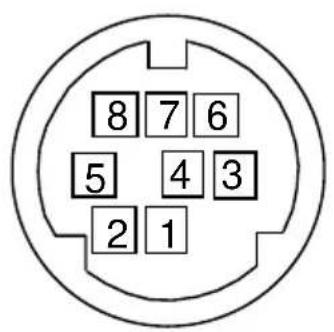
| No. | Signal |
| 1 | DTR |
| 2 | DSR |
| 3 | TXD |
| 4 | GND |
| 5 | RXD |
| 6 | GND |
| 7 | NC |
| 8 | NC |
● Din8 to D-Sub9 Cable Pin Definition
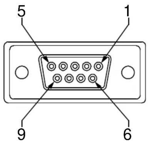
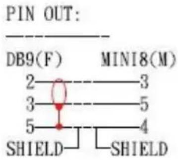
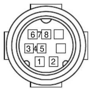
RS-422
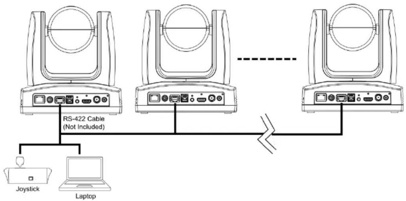
flowchart
graph TD
    A["RS-422 Cable (Not Included)"] --> B["Joystick"]
    A --> C["Laptop"]
    D["RS-422 Cable"] --> E["RS-422 Cable"]
    style A fill:#f9f,stroke:#333
    style B fill:#ccf,stroke:#333
    style C fill:#ccf,stroke:#333
    style D fill:#f9f,stroke:#333
    style E fill:#ccf,stroke:#333
[Notes] Use cat5e splitter for multi-camera connection.
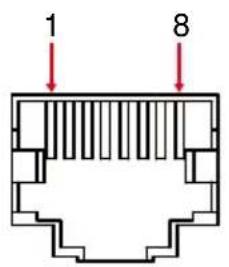
| RS-422 Pin | |||
| No. | Pin | No. | Pin |
| 1 | TX- | 5 | TX+ |
| 2 | TX+ | 6 | RX+ |
| 3 | RX- | 7 | RX- |
| 4 | TX- | 8 | RX+ |
Cat5e splitter pin assignment:
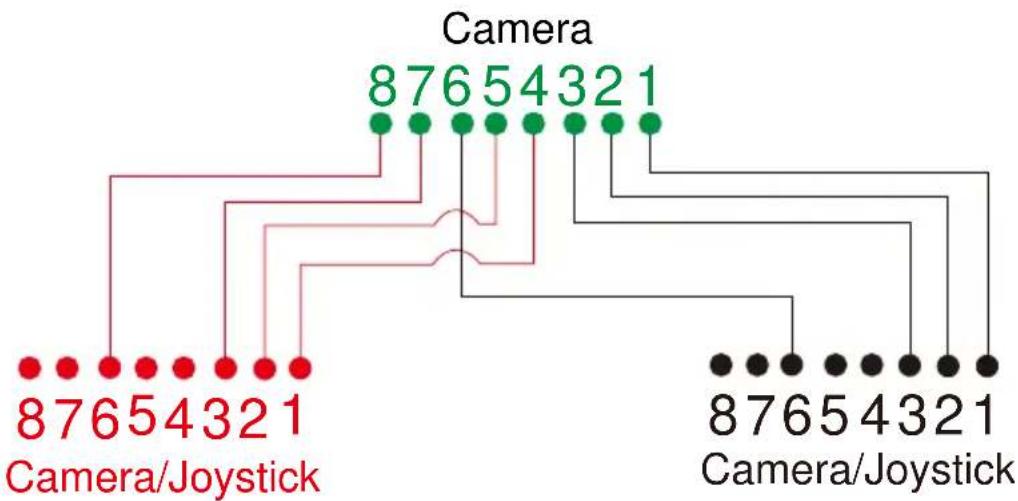
flowchart
graph TD
    A["87654321 Camera/Joystick"] --> B["87654321"]
    B --> C["87654321"]
    C --> D["87654321"]
    D --> E["87654321"]
    E --> F["87654321"]
    F --> G["87654321"]
    G --> H["87654321"]
    H --> I["87654321"]
    I --> J["87654321"]
    J --> K["87654321"]
    K --> L["87654321"]
    L --> M["87654321"]
    M --> N["87654321"]
    N --> O["87654321"]
    O --> P["87654321"]
    P --> Q["87654321"]
    Q --> R["87654321"]
    R --> S["87654321"]
Audio Input Connection
Connect the audio device for audio receiving.
[Notes]
● Line input level: 1Vrms (max.).
● Mic input level: 50mVrms (max.); Supplied voltage: 2.5V.
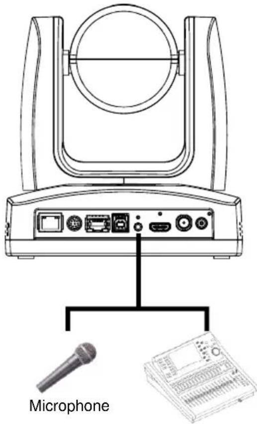
Audio Mixer
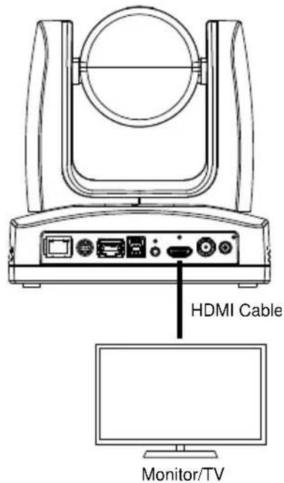
Video Output Connection
• HDMI
Use the HDMI cable to connect with monitor or TV for video output.
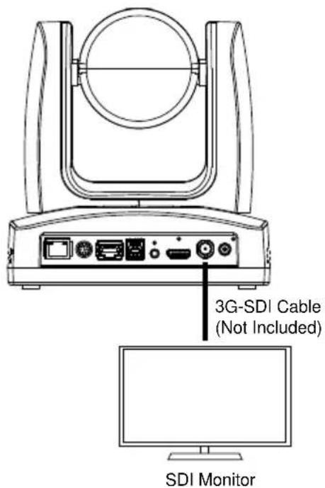
- 3G-SDI
Connect to 3G-SDI monitor for video output.
[Notes]
- HDMI and 3G-SDI monitors can be connected to camera and output live video simultaneously. When the HDMI monitor is well connected before the camera is turned on, the OSD menu will be displayed on HDMI monitor as default.
- The model name with "H" do not have 3G-SDI.
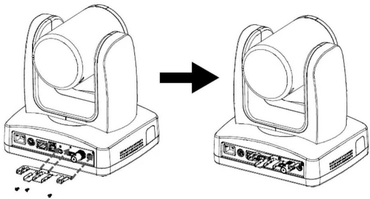
Cable Fixing Plate Installation
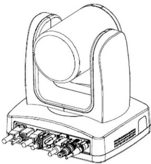
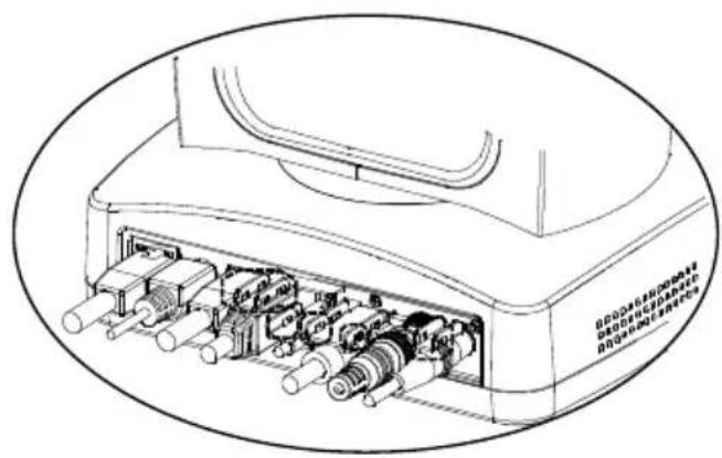
- Secure the cable fixing plate to the camera.
Screws: 3 M2 x 4mm screws (included in the package).
natural_image
Diagram showing device transformation from a multi-stage computer to a multi-stage computer, with no visible text or symbols.- Plug in cables.
natural_image
Technical line drawing of a mechanical device with multiple ports and a central cylindrical component (no text or symbols)- Use 4 cable ties to secure the cables and cable fixing plate.
Ceiling Mount Installation
- Secure the mount bracket on the ceiling. Screw: 4 screws, M4 x 10mm (Not Included in the package)
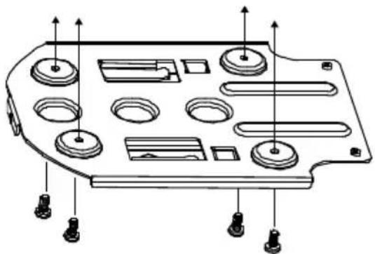
natural_image
Technical line drawing of a mechanical component with multiple circular features and mounting holes (no text or symbols)- Install the mount bracket on the camera. Screw: 2 screws, 1/4"-20 L=6.5mm (Included in the package)
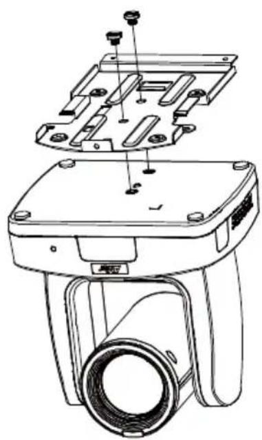
natural_image
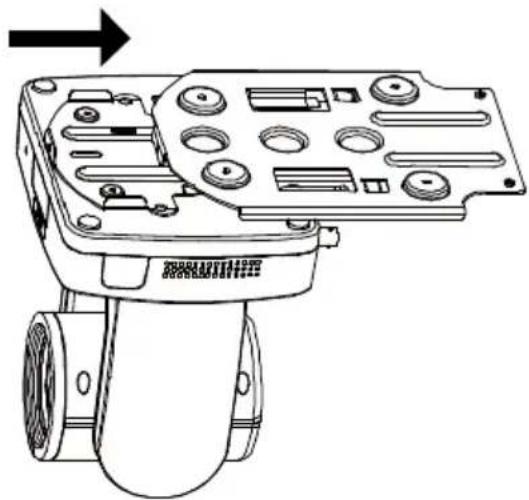
Technical line drawing of a camera module with mounting holes and internal components (no text or symbols)- Slide the mount bracket with the camera into the mount bracket which secured on the ceiling.
natural_image
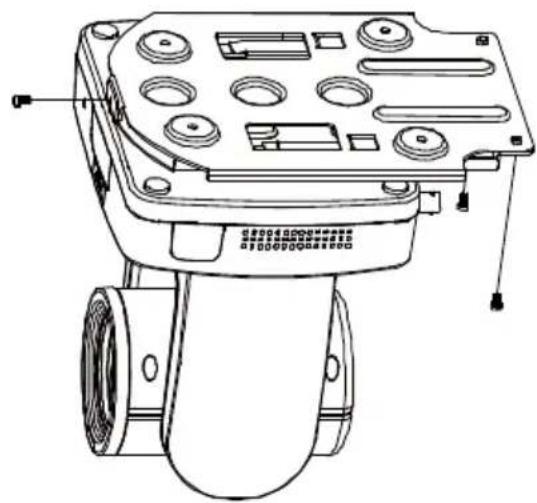
Technical line drawing of a mechanical device with multiple circular components and a cylindrical housing (no text or symbols)- Secure the camera with screws. Screw: 3 screws, M3 x 6mm (Included in the package)
natural_image
Technical line drawing of a mechanical device with mounting holes and wheels (no text or symbols)[Notes] Connect necessary cables after sliding the camera into the mount bracket.
Camera Installation
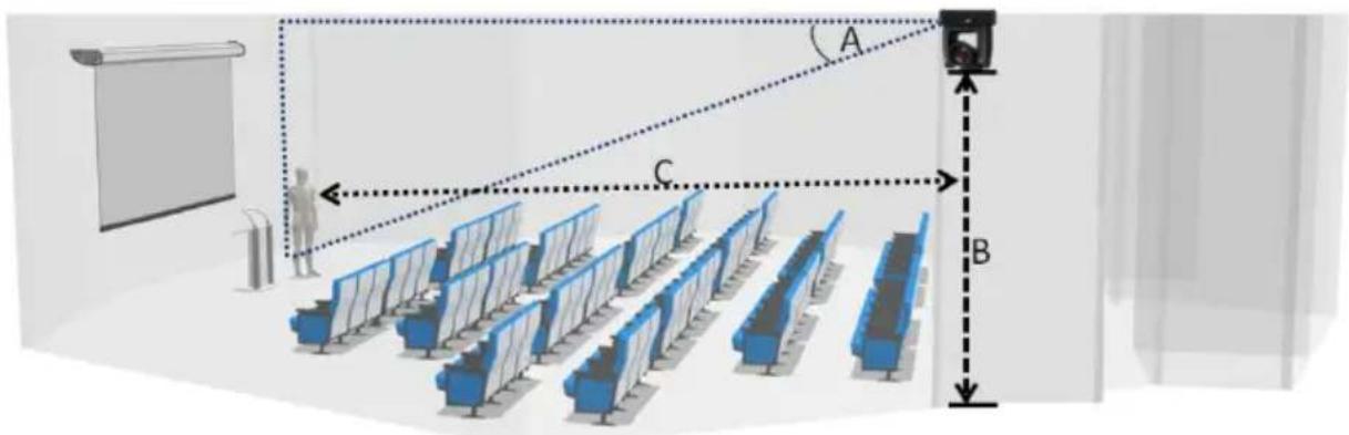
- Angle A: less than 30^
● Height B: 2\~3m from floor
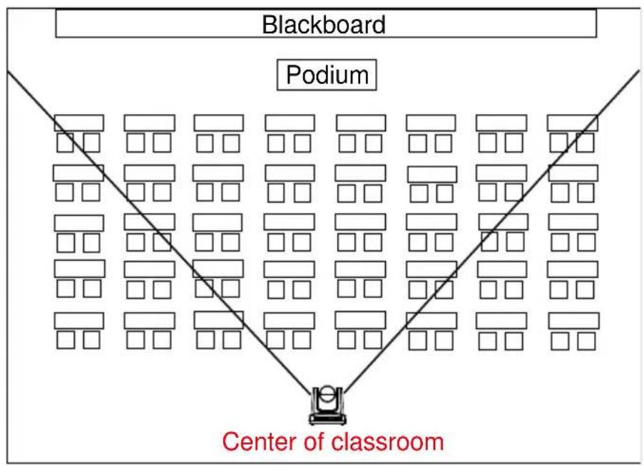
● Distance C: longer than 3m away from podium - Position: center of classroom
- Distance between the camera and tracking target (presenter):
| Optical zoom ratio ability | Upper body size | Full body size |
| 12X | 3~16m | 3~28m |
| 16X | 3~30m | 4~55m |
| 21X | 3~40m | 4~65m |
| 30X | 3~44m | 3~76m |
Remote Control
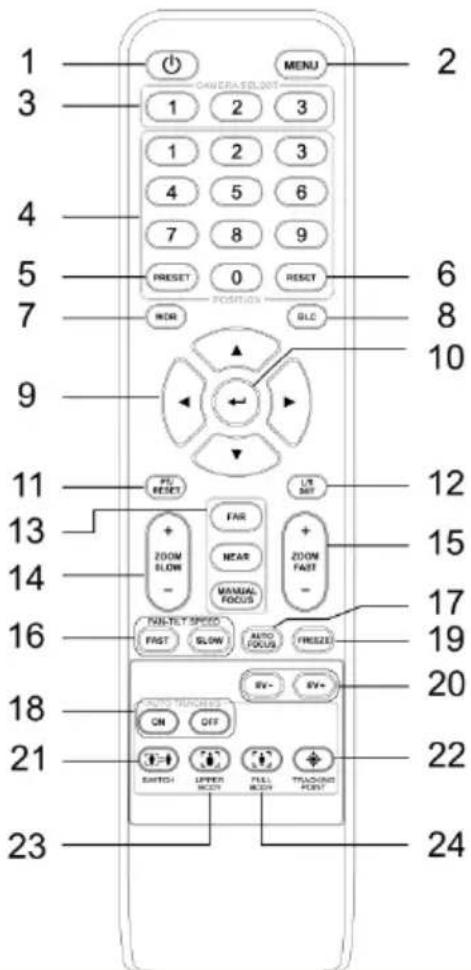
| Name | Function | |
| 1 | Power | Turn the camera on/standby. |
| 2 | Menu | Press the button to open OSD menu during HDMI output. |
| 3 | Camera Select | Set cameras to CAM1 to CAM3 button.Select a camera to operate. |
| 4 | Number Pad | ● Set the preset position 0~9.● Press number button (0~9) to move the camera to pre-configured preset position 0~9. |
| 5 | Preset | Press and hold Preset, then short press Number button (0~9), and then release both buttons to save the preset position. |
| 6 | Reset | Press and hold Reset + short press Number button (0~9), and release all to reset preset position. |
| 7 | WDR | Turn on/off Wide Dynamic Range function. |
| 8 | BLC | Turn on/off Backlight Compensation. |
| 9 | ▲,▼,◀, & ▶ | Press once for incremental movement or press and hold for continuous pan or tilt. |
| 10 | Enter | Access the OSD menu, confirm the selection or make a selection in OSD menu. |
| 11 | PT Reset | Reset the Pan-Tilt position. |
| 12 | L/R SET | ● Invert L/R Pan Direction: Press and hold L/R SET, then short press Position 2, and then release both buttons. ● Reset L/R Pan Direction: Press and hold L/R SET, then short press Position 1, and then release both buttons. |
| 13 | Far/Near/MF | Enable manual focus. Use Far/Near to adjust the focus. |
| 14 | Zoom +/- | Zoom in/out slowly. |
| 15 | Zoom Fast +/- | Zoom in/out fast. |
| 16 | Pan-Tilt Speed Fast/Slow | Pan-Tilt speed adjustment. |
| 17 | AF | Auto focus. |
| 18 | Auto Tracking | Auto Tracking ON/OFF. |
| 19 | Freeze | Freeze the live image. |
| 20 | EV +/- | ● Short press to adjust EV level. ● Long press EV+ to turn on RTMP. ● Long press EV- to turn off RTMP. |
| 21 | Switch | Change presenter. |
| 22 | Tracking Point | Press the button to enter Tracking Point (Preset Position 1). |
| 23 | Upper Body | Focus on the upper body of the presenter. |
| 24 | Full Body | Focus on the full body of the presenter. |
Set Up the Camera
OSD Menu
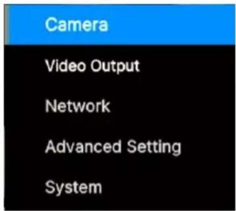
You can use the supplied Remote Control to operate the OSD Menu during HDMI output. Press the MENU button to call out the On-Screen Display (OSD) menu and use the ▲, ▼, ◀, ▶ and ← buttons to operate the OSD menu.
IP Address Setup
Static IP
- Press the MENU on the remote control to call out the OSD menu.
- Go to Network > Static IP.
[Notes] Turn the DHCP off before setting up static IP (Network > DHCP > Off).
- Select the IP Address, Gateway, Netmask and DNS to configure. Press ← and use ◀, ▶ and Number Pad to enter the data.
| Camera | ||||
| Video Output | ||||
| Network | DHCP | On | ||
| Advanced Setting | Static IP | > | IP Address | 192.168.1.168 |
| System | Gateway | 192.168.1.254 | ||
| Mask | 255.255.255.0 | |||
| DNS | 8.8.8.8 |
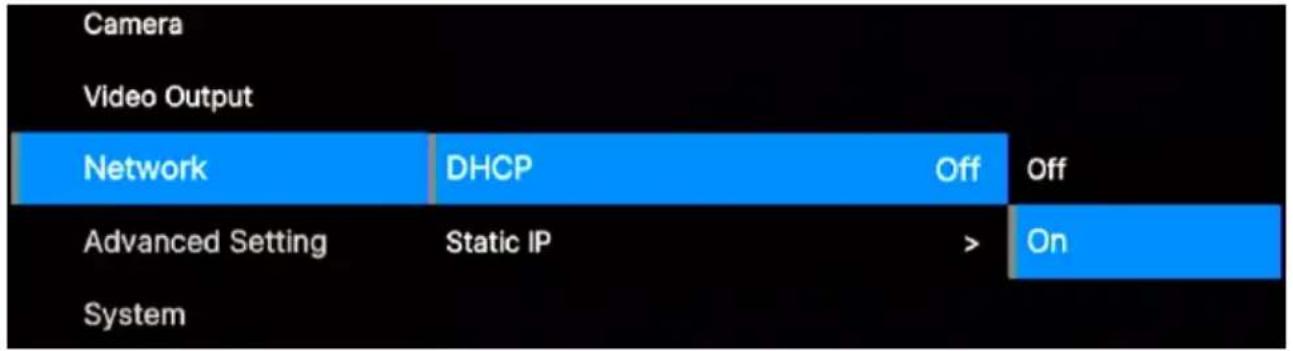
DHCP
- Press the MENON on the remote control to call out the OSD menu.
- Go to Network > DHCP > On.
flowchart
graph LR
    A["Camera"] --> B["Video Output"]
    B --> C["Network"]
    C --> D["DHCP"]
    D --> E["Off"]
    E --> F["Advanced Setting"]
    F --> G["Static IP"]
    G --> H[">"]
    H --> I["On"]
    I --> J["System"]
- After turning the DHCP on, the user can view IP address in System > Information.
| Camera | |||
| Video Output | |||
| Network | |||
| Advanced Setting | |||
| System | Camera Selector | 1 | |
| Status OSD | Off | ||
| Language | English | ||
| NDI | |||
| CameralD | TR335N | ||
| Tally | Disable | ||
| Information | > | Model Name TR335N | |
| Factory Default | > | Version 0.0.0001.20 | |
| Account Default | > | IP Address 10.100.90.20 | |
| MAC 00:18:1a:0c:ba:83 | |||
| Lens A020 | |||
| Mcu BB354DE9 |
OSD Menu Tree
Camera
Set up camera parameters: Exposure Mode, White Balance, Pan Tilt Zoom, Noise Reduction, Saturation, Contrast, Sharpness, Mirror and Flip.
| 1^st Layer | 2^nd Layer | 3^rd Layer | 4^th Layer | 5^th Layer |
| Camera | Exposure Mode | Full Auto | Exposure Value | -4/-3/-2/-1/0/1/2/3/4 |
| Gain Limit Level | 24dB/27dB/30dB/33dB/36dB/39dB/42dB | |||
| Slow Shutter | Off/On | |||
| Shutter Priority | Exposure Value | -4/-3/-2/-1/0/1/2/3/4 | ||
| Shutter Speed | 1/1, 1/2, 1/4, 1/8, 1/15, 1/30, 1/60, 1/90, 1/100, 1/125, 1/180, 1/250, 1/350, 1/500, 1/725, 1/1000, 1/1500, 1/2000, 1/3000, 1/4000, 1/6000, 1/10000 | |||
| Gain Limit Level | 24dB/27dB/30dB/33dB/36dB/39dB/42dB | |||
| Iris Priority | Exposure Value | -4/-3/-2/-1/0/1/2/3/4 | ||
| Iris Level | F1.6/F2.0/F2.4/F2.8/F3.4/F4.0/F4.8/F5.6/F6.8/F8.0/F9.6/F11/F14/Close | |||
| Gain Limit Level | 24dB/27dB/30dB/33dB/36dB/39dB/42dB | |||
| Slow Shutter | On/Off | |||
| Manual | Shutter Speed | 1/1, 1/2, 1/4, 1/8, 1/15, 1/30, 1/60, 1/90, 1/100, 1/125, 1/180, 1/250, 1/350, 1/500, 1/725, 1 /1000, 1/1500, 1/2000, 1/3000, 1/4000, 1/6000, 1/10000 | ||
| Iris Level | F1.6/F2.0/F2.4/F2.8/F3.4/F4.0/F4.8/F5.6/F6.8/F8.0/F9.6/F11/F14/Close | |||
| Gain Level | 0dB/3dB/6dB/9dB/12dB/15dB/18dB/21dB/24dB/27dB/30dB/33dB/36dB/39dB/42dB | |||
| Bright | 0, 5-31 | - | ||
| Camera | White Balance | Auto | - | - |
| ATW | - | - | ||
| Indoor | - | - | ||
| Outdoor | - | - | ||
| One push | - | - | ||
| Manual | R Gain (0-255) | - | ||
| B Gain (0-255) | - | |||
| Pan Tilt Zoom | Preset Speed | 5/25/50/100/150/200 | - | |
| Digital Zoom | Off/On | - | ||
| Digital Zoom Limit | x2-x12 | - | ||
| Pan/Tilt Slow | Off/On | - | ||
| Noise Reduction | Off/Low/Medium/High | - | - | |
| Saturation | 0-10 | - | - | |
| Contrast | 0-4 | - | - | |
| Sharpness | 0-3 | - | - | |
| Mirror | Off/On | - | - | |
| Flip | Off/On | - | - | |
| LDC* | Off/On | - | - |
*Only certain camera models support LDC function, please refer to the table below.
Supported AVer Cameras:
| PTC300V2 Series | PTC500 Series | PTC330 Series | PTC310 Series | PTC115 Series |
| PTC330UV2 | PTC500S | PTC330 | PTC310 | PTC115 |
| TR333V2 | TR530 | TR331 | TR311 | TR320 |
| PTC320UNV2 | PTC500+ | PTC330N | PTC310U | PTC115+ |
| TR323NV2 | TR530+ | TR331N | TR313 | TR320+ |
| PTC320UV2 | PTC330U TR333 | PTC310H | ||
| PTC310N | ||||
| TR311N | ||||
| PTC310UN | ||||
| TR313N | ||||
| PTC310HN |
V3 Series
TR335
TR335N
*US model name in italics.
Video Output
Select video resolution (2160p is only supported on certain models).
| 1^st Layer | 2^nd Layer | 3^rd Layer |
| Video Output | Theme Mode | Standard/Zoom/Teams/(NDI) |
| Frequency | 50Hz/59.94Hz/60Hz | |
| Resolution | 2160P/30, 2160P/60, 1080P/60, 1080P/30, 1080I/60, 720P/60 |
Network
Set up IP mode – DHCP or Static IP.
| 1^st Layer | 2^nd Layer | 3^rd Layer |
| Network | DHCP | Off/On |
| Static IP | IP Address, Gateway, Mask, DNS |
Advanced Setting
| 1^st Layer | 2^nd Layer | 3^rd Layer | 4^th Layer |
| Advanced Setting | Audio | Input Type | Line In/Mic In |
| Audio Volume | 0-10 | ||
| Control | Serial Port | RS-232/RS-422 | |
| Protocol | VISCA/PELCO D/PELCO P | ||
| Camera Address | 1-7 | ||
| Baud Rate | 4800/9600/38400 | ||
| Tracking | Off/On | - | |
| Tracking Mode | Presenter | - | |
| Zone | - | ||
| Hybrid | - |
System
- Status OSD: Enable/disable Preset status (Save Preset, Call Preset, Cancel Preset) display on the screen.
- Camera Selector: Set the camera ID 1\~3 for using remote control on multiple cameras control (also see No.3 Camera Select in Remote Control chapter).
- NDI: Enable/disable NDI function.
- Tally: Enable tally function.
| 1^st Layer | 2^nd Layer | 3^rd Layer |
| System | Camera Selector | 1-3 |
| Status OSD | Off/On | |
| Language | English/繁體中文/日本語/简体中文/한국어/ Tiếng Việt | |
| NDI | Off/On | |
| Tally | Disable/Enable | |
| Information | Model Name/Version/IP Address/MAC/Lens/Mcu | |
| Factory Default | Off/On | |
| Account Default | Off/On |
Connect the camera from a remote site through the internet.
Access the Web Interface of the Camera
To access the camera Web interface, you have to use AVer IPCam Utility or AVer PTZ Management software to search camera IP address.
Access the Camera via AVer IPCam Utility
To use AVer IPCam Utility to find the camera IP address:
- Download the AVer IPCam Utility from
https://www.aver.com/Downloads/search?q=AVer%20IPCam%20Utility%20for%20Camera%20IP%20Searching and launch the application. - Click Search to view all available devices on the screen.
- Click to select a camera from the list to view the camera info in the Settings field.
- The default network of the camera is Static IP (192.168.1.168) and default ID/Password are admin/admin. If you want to configure the network to DHCP, enter the ID/Password in the Login field, select the "camera model" on the list, select "DHCP" and then click the Apply button.
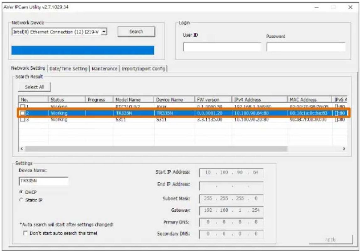
- To access the Web interface, double-click on the IP address in the IPv4 Address column.
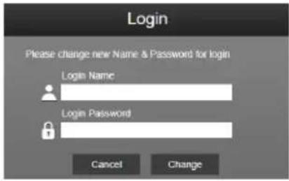
For the first-time user, you will be prompted with a Login window to change the ID and password.
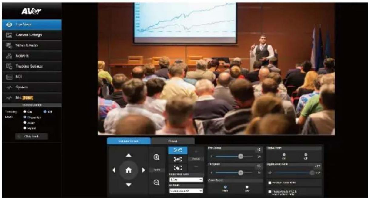
- Login with the new ID/Password, the Web interface of the camera will be displayed (Chrome browser). Please refer to
chapter for more details.
[Notes] If IPCam utility cannot find the camera, please check the following:
- Please make sure the Ethernet connection of the camera is well connected.
● The camera and PC (IPCam Utility) are in the same LAN segment.
Accessing the Camera via AVer PTZ Management
Use AVer PTZ Management to find the IP address of your cameras, follow the steps below.
- Download the AVer PTZ Management software from https://www.aver.com/download-center.
- Download the Windows program and install it.
- Set up the user ID and password, and log in to the software (default User Name/Password: admin/admin).
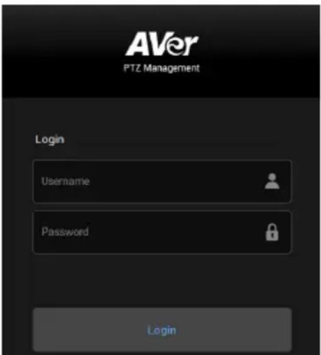
- On the Main page of PTZ Management, click Setup > Add > click Auto Search. The cameras connected on the same LAN with the computer will be displayed.
- Click on the camera and enter the camera ID and Password to add the camera to the device list (default ID/Password are admin/admin). Click Go to Web to access the camera web application.
Live View
You can control the camera and operate the Preset functions using this page.
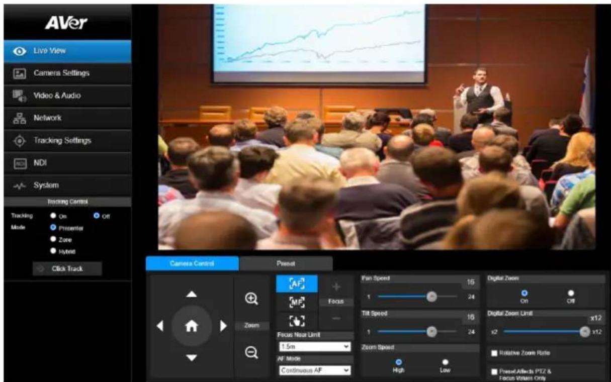
Camera Control
Click the Camera Control tab to display the panel below for operation.
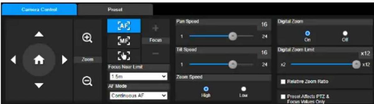
● Pan-Tilt-Zoom Control
Use the directional buttons to navigate the camera view. Adjust the Pan Speed and Tilt Speed if necessary.
Use + and - to zoom in or zoom out the live image. You can also select Zoom Speed (High/Low).
Click to go back to home (default) position.
- Focus
| Item | Description |
| Auto Focus | Click to perform the auto focus. |
| Manual Focus | Click to manually adjust the focus. You can use the Focus + and Focus – buttons to adjust the focus. |
| One-push Focus | Click to automatically adjust the focus right away. |
| Focus Near Limit | Set the focus distance limit. |
| AF Mode | If Auto Focus is selected, you can further set up the AF Mode.Continuous AF: The camera will automatically adjust focus all the time.AF Trigger after PTZ: The camera will automatically adjust focus each time after performing the pan, tilt or zoom functions. |
- Digital Zoom
| Item | Description |
| Digital Zoom | Select On or Off to enable or disable the function. |
| Digital Zoom Limit | Adjust the digital zoom from x2 to x12. |
| Relative Zoom Ratio | Turn on or off the function. If you turn on Relative Zoom Ratio, the pan/tilt speed will be automatically adjusted based on the zoom ratio.The more the zoom ratio, the slower the pan/tilt speed. |
| Preset Affects PTZ & Focus Values Only | Turn on this function to save only the value of pan, tilt, zoom and focus for the configured preset points. |
Preset
Click the Preset tab to display the panel below. You can edit and operate the preset positions.
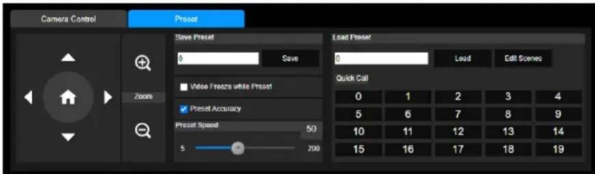
To set up preset positions:
- Go to Live View > Preset.
- Use the directional buttons to navigate the camera view. Optionally use + and - to zoom in or zoom out the images.
- Enter a preset number (0\~255) in the Save Preset column and click Save to save the position.
To move camera to preset positions:
- Enter a preset number (0\~255) in the Load Preset column or click a preset number (0\~19) in the Quick Call section.
- Click Load, the camera will move to the preset position.
When operating the go to preset positions, you can optionally adjust the Preset Speed or turn on or off the Video Freeze while Preset function.
- Video Freeze with Preset: When you turn on this function, the camera will not display the view along the path when moving from one position to another. The camera will only display the view of the positions.
- Preset Speed: Drag the slider to adjust the moving speed from one preset position to another. (5\~200)
To customize camera functions at each preset positions:
- Go to Live View > Preset > Edit scenes.
- Click Scenes 0\~9 to add up to 10 CGI commands (follow the format of https://username:password@URL) for each scene.
- Select a Scene from the Scenes drop-down list to pair Preset 0\~9 with Scene 0\~9.
- Click Append to add CGI commands, and click Remove to delete CGI commands. When finished, click Save.
Camera Settings
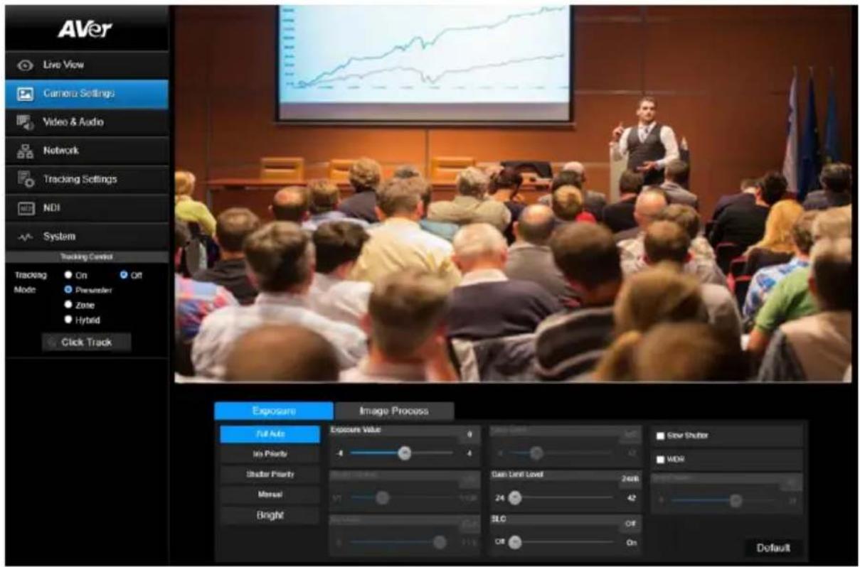
Exposure
Click the Exposure tab to display the panel below for configuration.
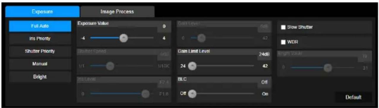
| Item | Description |
| Exposure Mode | Options include Full Auto, Iris Priority, Shutter Priority, Manual and Bright. Select an exposure mode and optionally adjust the value of Exposure Value, Gain Level, Shutter Speed, Gain Limit Level, Iris Level, BLC and Bright Value. |
| Slow Shutter | Select the checkbox to let more light enter the lens. |
| WDR | Select the checkbox to turn on Wide Dynamic Range mode for more vivid camera view. |
Click Default to reset the Exposure settings to factory default.
Image Process
Click the Image Process tab to display the panel below for configuration.
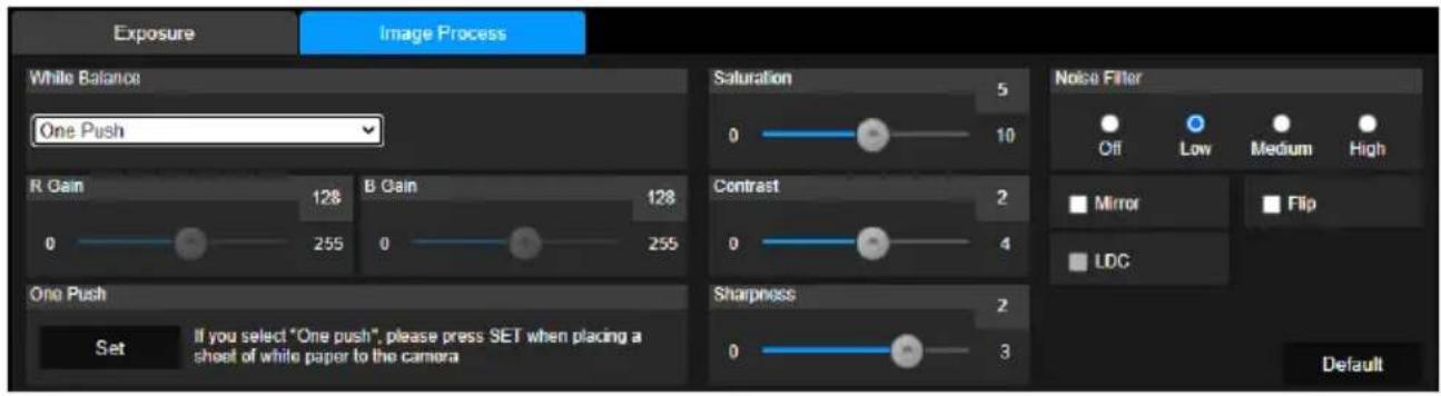
| Item | Description |
| White Balance | Options include AWB, ATW, Indoor, Outdoor, One Push and Manual.● SelectManualto adjust theR Gainand B Gainmanually.● SelectOne Push, and clickSetin theOne Pushfield when placing a white paper sheet in front of the camera lens. |
| Saturation | Drag the slider to adjust the value. |
| Contrast | Drag the slider to adjust the value. |
| Sharpness | Drag the slider to adjust the value. |
| Noise Filter | Select fromOff, Low,MiddleorHighto adjust the noise filter. |
| Mirror | Select the checkbox to flip the camera view horizontally. |
| Flip | Select the checkbox to flip the camera view vertically. |
| LDC | Turn on or off Lens Distortion Correction. Turn on this function to automatically correct image distortion caused under certain zoom level. |
Video & Audio
You can configure video and audio settings on this page.
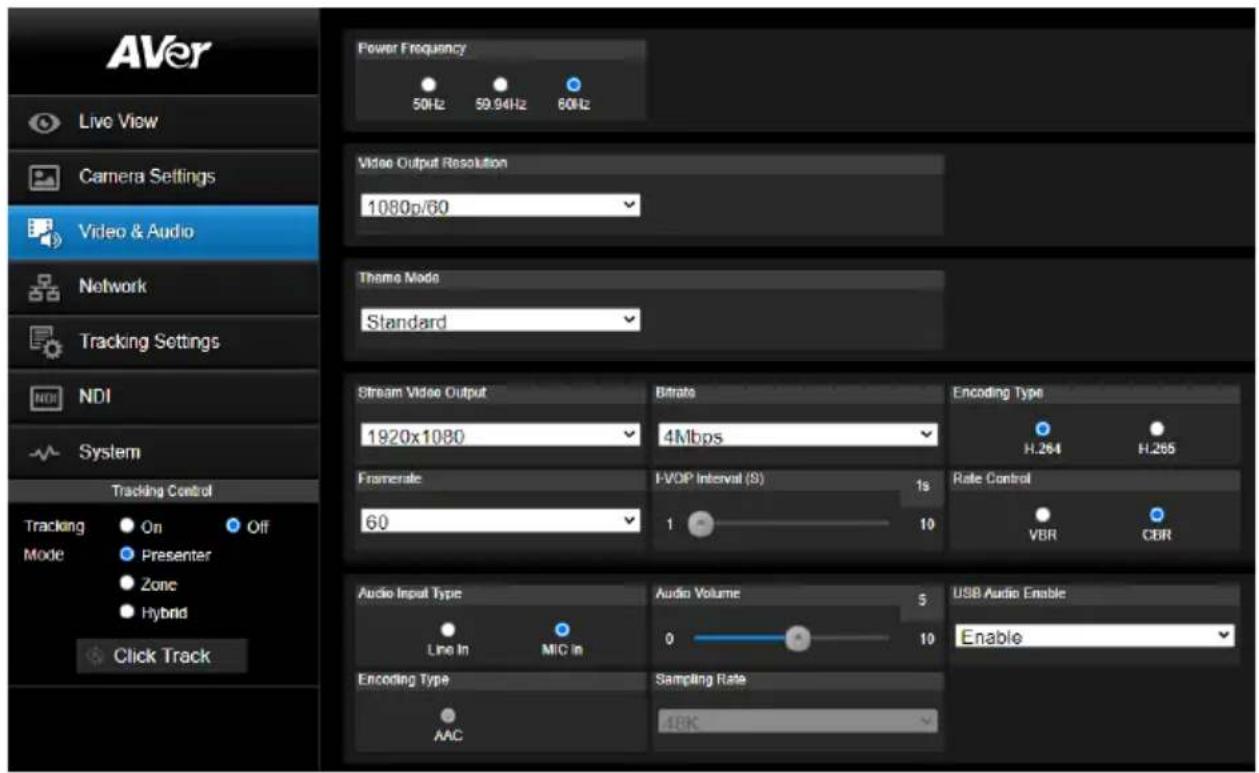
● Video and Audio Settings
| Item | Description |
| Power Frequency | Select from 50Hz, 59.94Hz or 60Hz based on your region. |
| Video Output Resolution | Select a resolution to display on your video output device. |
| Theme Mode | Select to a theme mode for your video output from the drop-down list. |
| Stream Video Output | Select a stream resolution on live view from the drop-down list. |
| Bitrate | Select a bitrate from the drop-down list. |
| Framerate | Select a framerate for live stream – 1, 5, 15, 20 or 30 for power frequency 59.94Hz or 60Hz; 1, 5, 15, 20 or 25 for power frequency 50Hz. |
| I-VOP Interval (S) | Drag the slider to set the value from 1s to 10s. |
| Encoding Type (video) | Select H.264 or H.265 to encode streaming video. |
| Rate Control | Select VBR or CBR. |
| Audio Input Type | Select to input audio by Line in or Mic in. |
| Audio Volume | Drag the slider to set the volume from 0 to 10. |
| Encoding Type (audio) | Select to encode audio. |
| Sampling Rate | Select a sampling rate from the drop-down list. |
| USB Audio Enable | Select from the drop-down list to turn on or off the setting. |
Network
You can configure network settings on this page.
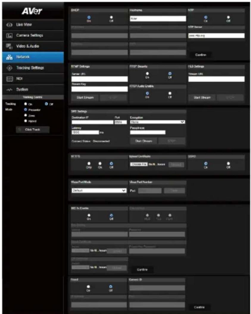
| Item | Description |
| DHCP | You can set up the network to DHCP or Static IP.DHCP: Select On to assign the related IP settings with the camera automatically. Click Confirm to save the settings.Static IP: Select Off to manually enter the IP Address, Netmask, Gateway and DNS. Click Confirm to save the settings. |
| Hostname | The default Hostname is TR335N. You can change the hostname to be displayed on other devices, e.g. IP router. |
| NTP | Select to turn the function On or Off.When NTP is On, enter NTP Server into the text box. |
| RTMP Settings | Change the RTMP settings to transfer camera stream to the broadcasting platform, e.g. YouTube.To set up the RTMP settings:1. Enter the Server URL and Stream Key of the broadcasting platform. Please refer to the instruction of the broadcasting platform you use to get the RTMP server URL and stream key.2. Click Start Stream, the camera stream will direct you to your broadcasting platform.3. To stop broadcasting, click STOP. |
| RTSP Security | Change the RTSP settings to display camera streams on applications such as VLC, PotPlayer or Quick Time to use RTSP streaming.To enable RTSP:1. Select On in the RTSP Security field.2. Select On in the RTSP Audio Enable field if you want to transfer audio.3. On your application, enter the RTSP(ex: rtsp://192.168.1.100/live_st1) and ID/Password of the camera. |
| HLS Settings | To transfer the HLS streaming, enter the Stream URL and click Start Stream. Click STOP to stop transferring. |
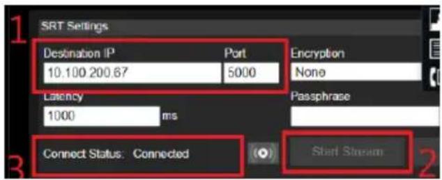
| SRT Settings | Enter Destination IP, Encryption, Latency and Passphrase.When finished, click Start Stream.Click STOP to stop streaming. |
| HTTPS | Turn on HTTPS to establish a secure connection between your browser and your camera.To turn on HTTPS access on your camera:1. Create a SSL certificate file for encryption and decryption.2. In the HTTPS setup field, select On and then click Choose File to select the certificate file.3. Click Upload. |
| Upload Certificate | Click Choose File to upload a SSL certificate (must be in the PEM format) to PTC/PTZ/DL cameras.To create this format:1. Prepare your certificate, intermediate certificates, and the CA root in a base-64 encoded format. Additionally, prepare the private key in the PKCS#8 format (should be unencrypted).2. Combine the certificates and the private key in a specified order to create the PEM format:----BEGIN PRIVATE KEY-----......----END PRIVATE KEY---------BEGIN CERTIFICATE-----...... |
----END CERTIFICATE----
| After the preparation, upload the SSL certificate. | |
| SSHD | Select to turn the function On or Off. |
| Visca Port Mode | Select from the drop-down list to set Visca Port Mode.After selected, enter Visca Port Number. |
| 802.1x Enable | Select to turn on or off the function. |
| Eap Method | After turning on 802.1x Enable function, select from MD5, TLS and PEAP to set up the function. |
| Eap Setting | After turning on 802.1x Enable function, enter Identify and Password.According to your Eap Method, import Client Certificate, Private Key Password, CA Certificate.When finished, click Confirm. |
| FreeD | Turn on FreeD protocol to send camera positioning data to a virtual reality production system.When FreeD is on, enter TR335N Camera ID, and the IP Address and Port of the device receiving positioning data. |
- SRT Settings
Example 1 vMix:
Set the workstation and the TR335N camera in the same network. Check the workstation's IP address (Destination IP). Example:
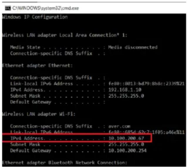
Select SRT (Listener) from Stream Type in vMix Input Select window.
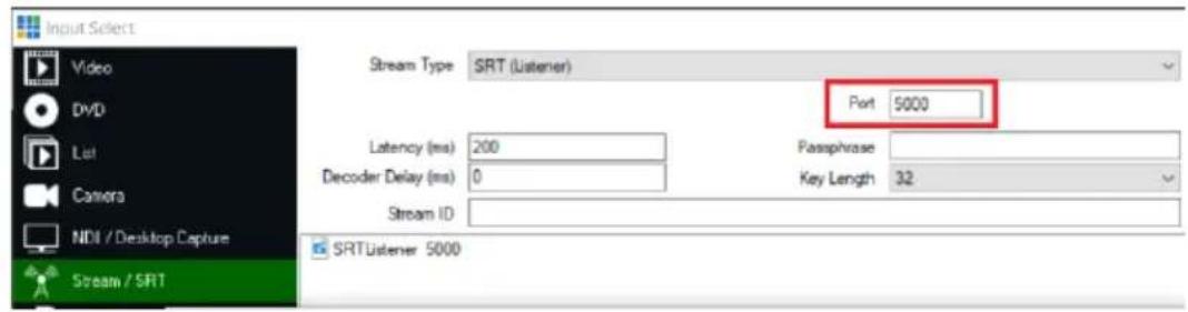
Enter the information into the SRT Settings TR335N web interface, then click on Start Stream, Connect Status shows Connected.
Example2 OBS (Open Broadcaster Software):
Set the workstation and the TR335N camera in the same network. Check the workstation's IP address (Destination IP). Example:
Connection-specific DNS Suffix . : aver.com
Link-local IPv6 Address . . . . . : fe80::f1dc:bcda:87bd:ac1e%12
IPv4 Address. . . . . . . . . . . : 10.100.105.127
Subnet Mask . . . . . . . . . . : 255.255.255.0
Default Gateway . . . . . . . . . : 10.100.105.254
Open OBS, add a scene, add a source, enter srt://Work Station IP:port?mode=listener Example: srt://10.100.105.127:8889?mode=listener
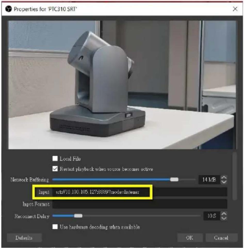
[Notes] If there is no image, please try right-click on the source->Transform->Fit to screen to re-scale image.
Tracking Settings
You can set up the tracking modes and use the Tracking Control panel to perform the tracking function. You can also turn on Gesture control to use your hands to control certain camera functions.
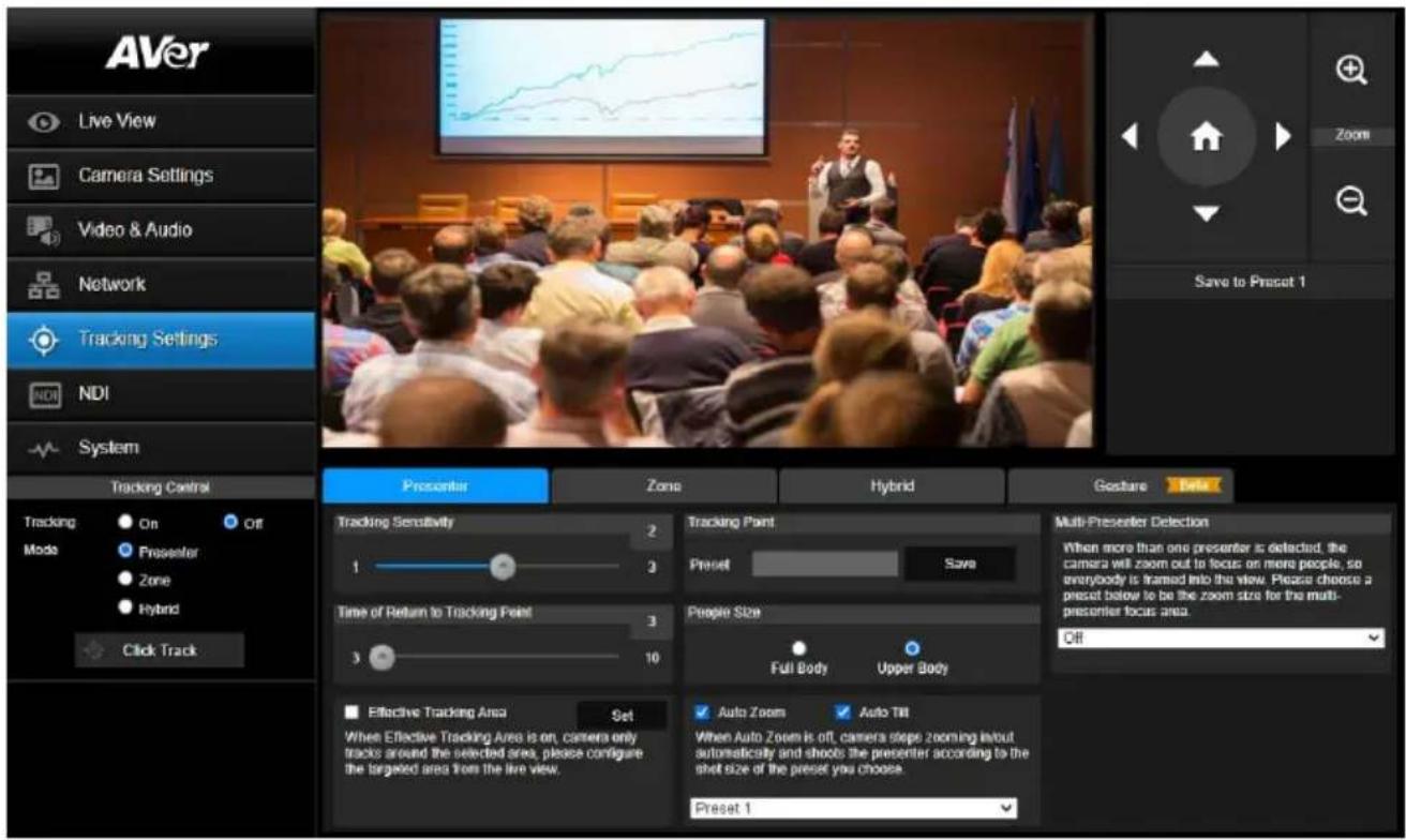
| Tracking Mode | Description |
| Presenter | Camera starts tracking when a presenter appears in the camera view. SelectUpper Bodyfor People Size, the camera will focus on the targeted presenter with less background. If the presenter is out of the camera view, the camera will return to the pre-configuredTracking Point. |
| Zone | Camera focuses on the pre-configured zones (preset areas) while tracking the presenter. |
| Hybrid | You can benefit from the advantages of both thePresenterand Zonemodes. The camera will start tracking when a presenter is detected in the camera view. If the position where a presenter enters is pre-configured as a tracking zone (preset area), the camera will activate as Zone tracking. |
To perform the tracking function, you can:
- On the camera web application, click Tracking Settings to set the tracking modes.
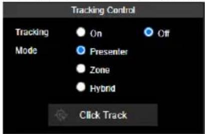
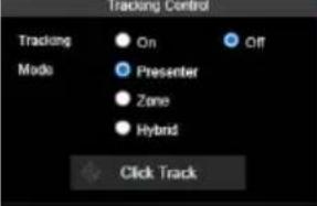
- Go to Tracking Control panel > select from Presenter, Zone and Hybrid mode. Optionally click the Click Track button if you want to select a new target presenter to track.
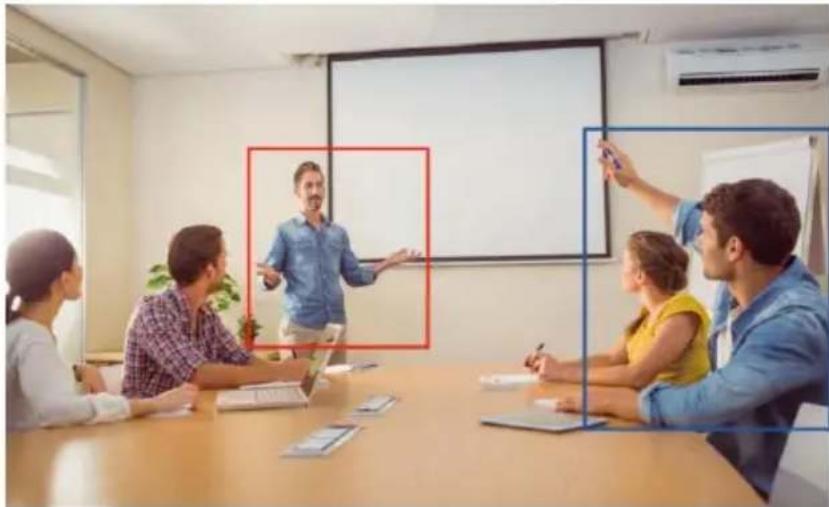
Click the Click Track button, the target presenter will be highlighted with a red frame, while the other detected presenters will be highlighted with blue frames.
natural_image
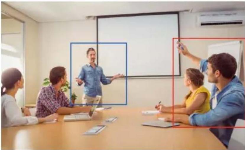
Group of people in a meeting room with a presenter pointing at a whiteboard (no visible text or symbols)Click on the presenter with a blue frame, the camera will change focus to the presenter you click.
natural_image
Group of people in a meeting room with a presenter pointing at a whiteboard (no visible text or symbols)Presenter Mode
Camera will start tracking when the presenter enters the camera live view.
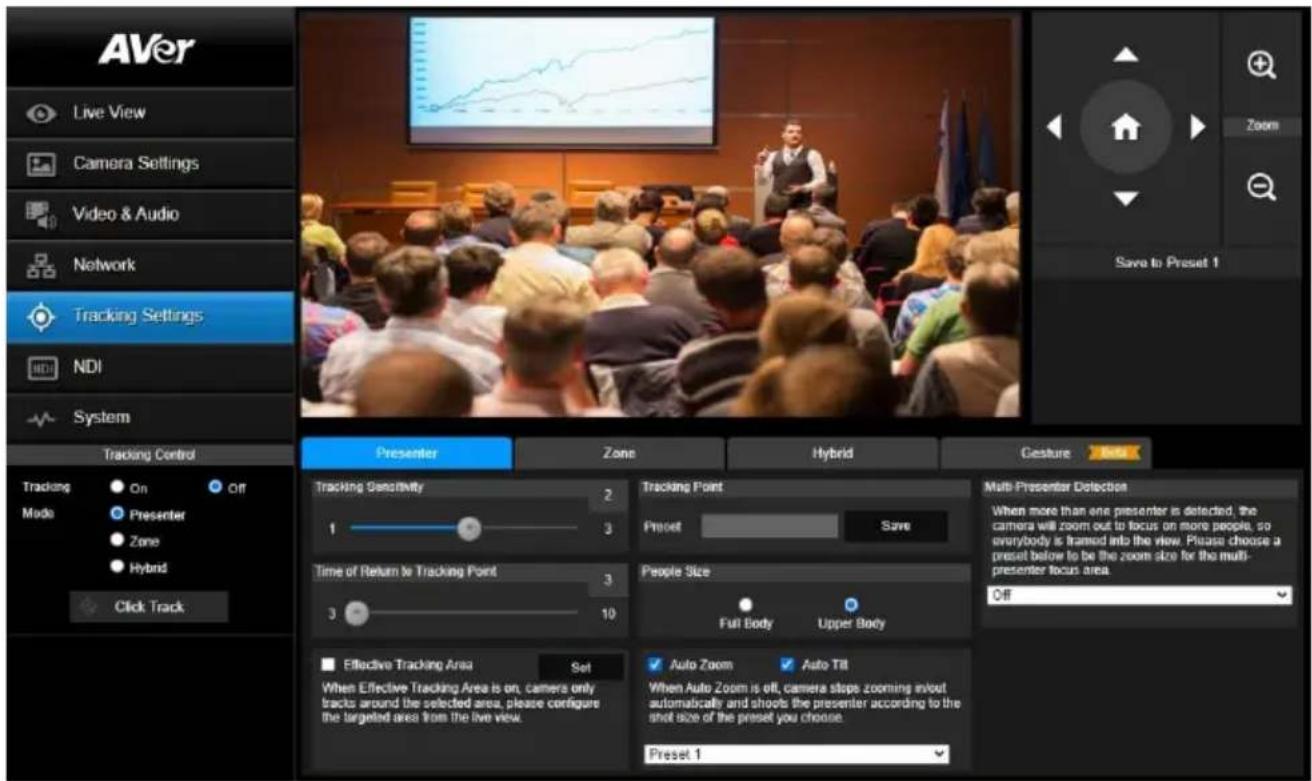
 | Description |
| Tracking Control | Click to turn on or off, and select a tracking mode. |
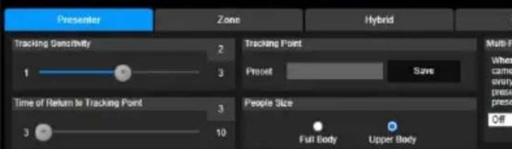
| Tracking Sensitivity | Drag the slide bar to adjust the sensitivity of the tracking function. |
| Tracking Point | Use the directional buttons,and to adjust the camera to a Tracking Point (preset position). Click Save to Preset 1 to save the Tracking Point.When no one is in view, the camera will go back to the Tracking Point (preset position). |
| Time of Return to Tracking Point | Set the idle time (sec.) for the camera to return to the Tracking Point. Drag the slider to adjust the value. |
| People Size | Select to track the presenter in Full Body (entire body) or Upper Body (up to 60% of body). |
| Effective Tracking Area | Set up a tracking area (optional). When Effective Tracking Area function is on, the camera only tracks around the selected area. Select the checkbox to enable the function and click the Set, a red frame appears in the preview window. Drag the upper-left or the lower-right corner of the red frame to adjust the tracking area. |
natural_image
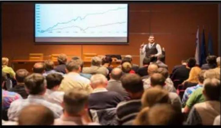
Audience giving a presentation in front of a large screen displaying a line chart (no visible text or labels)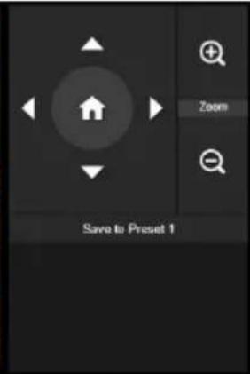

natural_image
Solid black image with no visible content or text.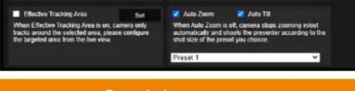
| Auto Zoom | When Auto Zoom is off, the camera stops zooming in/out automatically but keep the zoom size based on the preset point selected from the drop-down list below. |
| Auto Tilt | Select the checkbox to turn on the Auto Tilt function. |
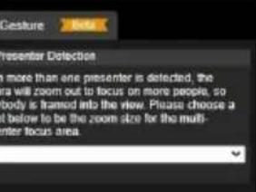
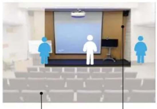
| Multi-Presenter Detection | When more than one presenter is detected, the camera will zoom out to frame every presenter in the camera view. To set up Multi-Presenter Detection, please refer to. |
Configuring Multi-Presenter Detection
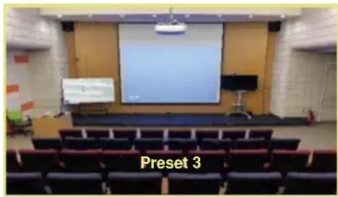
Set up a preset position for Multi-Presenter Detection. Ensure the camera view of this position fully covers the area where multiple presenters may appear. This preset position will be triggered when multiple presenters are detected.
To set up the preset position, go to Live View > Preset.
natural_image
Interior view of a modern auditorium with a large projection screen and rows of seats (no visible text or symbols)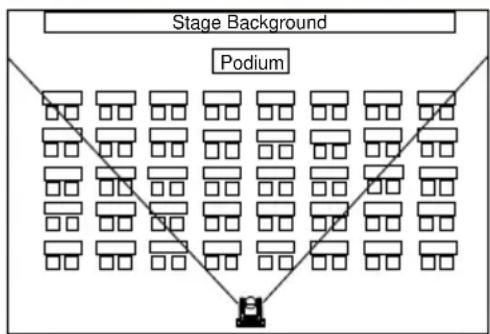
flowchart
graph TD
    A["Stage Background"] --> B["Podium"]
    B --> C["1"]
    B --> D["2"]
    B --> E["3"]
    B --> F["4"]
    B --> G["5"]
    B --> H["6"]
    B --> I["7"]
    B --> J["8"]
    B --> K["9"]
    B --> L["10"]
    style A fill:#f9f,stroke:#333
    style B fill:#ccf,stroke:#333
    style C fill:#cfc,stroke:#333
    style D fill:#fcc,stroke:#333
    style E fill:#cff,stroke:#333
    style F fill:#ffc,stroke:#333
    style G fill:#cfc,stroke:#333
    style H fill:#fcc,stroke:#333
    style I fill:#cfc,stroke:#333
    style J fill:#fcc,stroke:#333
    style K fill:#cfc,stroke:#333
    style L fill:#fcc,stroke:#333
To configure Multi-Presenter Detection:
- Go to Tracking Settings > Presenter setup page > select a pre-configured preset position (e.g. Preset 3) from the Multi-Presenter Detection drop-down list to turn on Multi-Presenter Detection function. Presenters appearing within the current camera view will trigger the Multi-Presenter Detection.
- Drag the slider of Time of Return to Tracking Point to adjust the duration when the camera loses track of the detected presenters and moves back to the selected preset point. By default, the dwell time set up with 3 second.
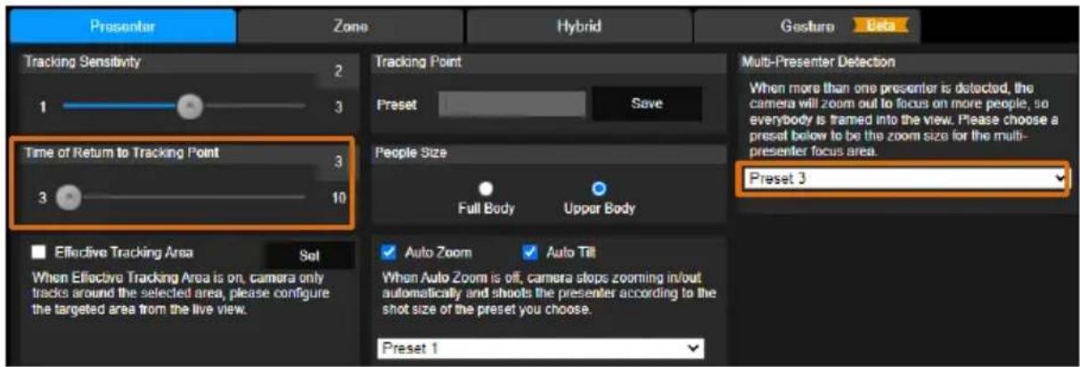
- When the Presenter tracking function is on, the Multi-Presenter Detection will be activated. To turn on the Presenter tracking, please refer to
. - To turn off the Multi-Presenter Detection function, go to Tracking Settings > Presenter setup page > select Off from the Multi-Presenter Detection drop-down list.
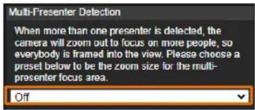
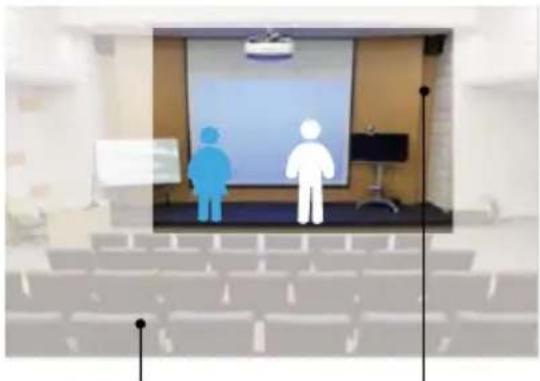
Multi-Presenter Detection will be triggered
natural_image
Interior view of a lecture hall with two human silhouettes on stage and a projection screen (no text or symbols visible)Multi-Presenter Detection
Multi-Presenter Detection will not be triggered
natural_image
Interior view of a lecture hall with three human figures standing on the stage and a presentation screen (no visible text or symbols)Current Camera ViewPreset Position bundled with Multi-Presenter Detection
Current Camera View
For example, when there is one presenter detected, the camera will perform single-presenter tracking, in which the camera view will focus on the presenter.
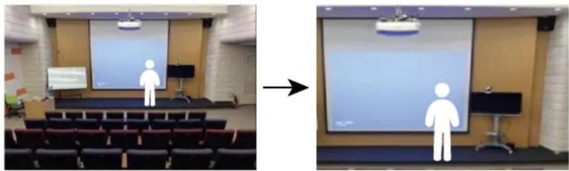
natural_image
Two presentation slides showing a person standing on a stage and another with a person standing on a podium, both without visible text or symbols.Meanwhile, when there is another presenter appears within the current camera view and then detected by the camera, the camera will be triggered to the pre-configured preset position.
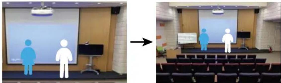
natural_image
Two presentation slides showing a group of human figures on stage, one with a projection screen and the other with a presentation board (no visible text or symbols)You can also use the supplied Remote Control to quickly set up the Presenter Mode.
-
Adjust the camera view properly and then save to preset 1 as the initial position.
-
Press Auto Tracking ON to turn on the function.
-
Press Upper Body to track the presenter with a closer view (up to 60% of body), or Full body to track the entire presenter in the view.
-
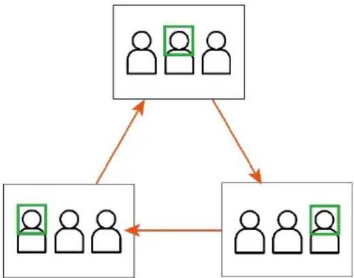
Press SWITCH to switch between presenters. Initially the camera tracks the one who is in the center of view. Every switch follows the sequence: left to right, then back to far left one in the camera view (see picture below).
-
To see which presenter is being tracked, press and hold FREEZE button to call/cancel engineering mode while tracking, you will see the tracked presenter is framed with a green box (Only during HDMI output).
flowchart
graph TD
    A["User Group 1"] --> B["User Group 2"]
    A --> C["User Group 3"]
    B --> D["User Group 4"]
    C --> D
    D --> A
    style A fill:#f9f,stroke:#333
    style B fill:#ccf,stroke:#333
    style C fill:#cfc,stroke:#333
    style D fill:#fcc,stroke:#333
Zone Mode
Set up the block areas for the camera to detect the presenter and track the presenter when the presenter appears within the pre-configured areas (preset areas).
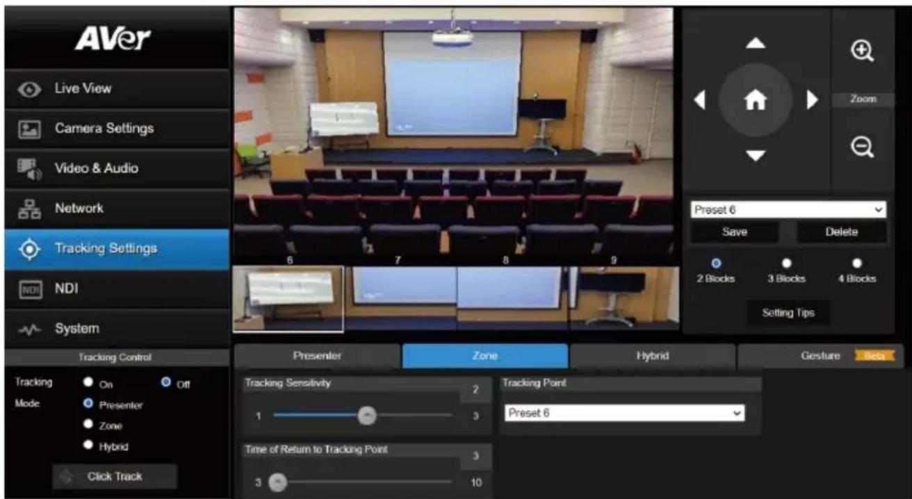
To configure the preset areas:
- Select the block number (2 Blocks, 3 Blocks or 4 Blocks) you want to configure for the preset positions. You can set up to 4 preset positions.
- Select a preset number from the drop-down list (Preset 6 \~ 9).
- Use the directional buttons, + and - to move the camera to the desired position.
- Click Save to save the position to the selected preset number. A preset thumbnail will be displayed below the preview window.
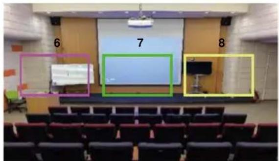
[Notes] To ensure smooth transition while tracking the presenter, please OVERLAP the set up preset areas. Do not separate the preset areas.
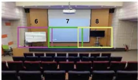
Ensure to overlap the preset areas
natural_image
Interior view of a lecture hall with a projector screen and audience seating (no visible text or symbols)Do not separate the preset areas
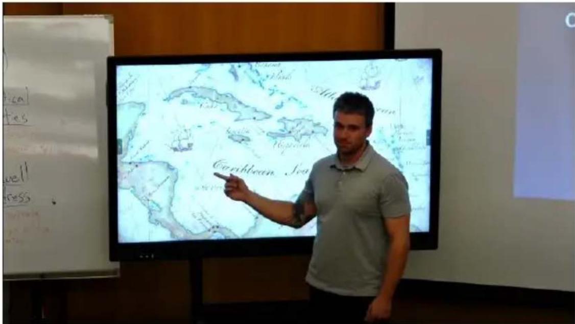
Set up the preset view to clearly see the preseter at least complete half body (60% upper body) to ensure tracking accuracy. Make sure there is no any other human-outline poster/TV/monitor in the background. The result of the Zone Mode is illustrated as below.
- Adjust the value or turn on the functions below.
| Item | Description |
| Tracking Sensitivity | Drag the slider to adjust the sensitivity of the tracking function. |
| Tracking Point | When losing tracking target, the camera will go back to the Tracking Point (preset position). To set up the Tracking Point, refer to step 1. |
| Time of Return to Tracking Point | Set the idle time (sec.) for the camera to return to the Tracking Point. Drag the slider to adjust the value. |
- You can also use the supplied Remote Control to quickly set up the Zone Mode. Press the Auto Tracking "On" button to turn on tracking function. Long press Tracking Point to switch tracking mode from Presenter Mode to Zone Mode (the hotkey supported at firmware v0.0.0000.21 or later).
- By default, 2 Blocks has initially selected if you use the Remote Control to set up the Zone Mode. If you want to configure more blocks, you will have to use the Web interface for setup.
- Adjust the camera view properly and then save to preset 6 and preset 7. By default, preset 6 is initially selected to be the first position to set up.
Hybrid Mode
You can benefit from the advantages of both the Presenter and Zone modes. The camera will start tracking when a presenter is detected in the camera view. If the position where a presenter enters is pre-configured as a tracking zone (preset area), the camera will activate as Zone tracking.
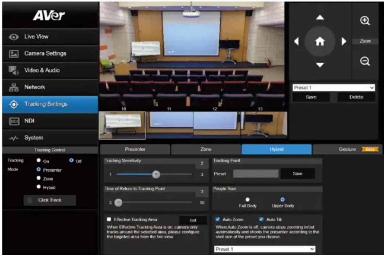
Set up a Tracking Point. When losing tracking target, the camera will go back to the Tracking Point (preset position).
To set up the Tracking Point:
- Select Preset 1 from the drop-down list.
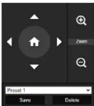
- Use the directional buttons, + and - to adjust the camera view.
- Click Save to save this preset point as the Tracking Point.
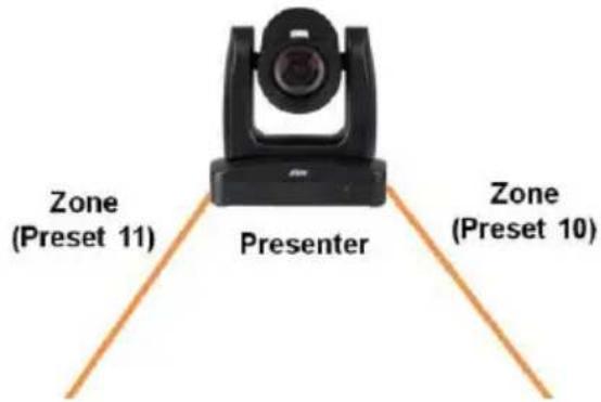
To better perform the Hybrid Mode, DO NOT overlap the zones (preset areas) nor configure the zones close to each other. It's recommended to leave some distance among the zones.
Adjust the value or turn on the below functions:
| Item | Description |
| Tracking Sensitivity | Drag the slider to adjust the sensitivity of the tracking function. |
| Tracking Point | 1. Select a preset number from the drop-down list (Preset 10 ~ 13).2. Use the directional buttons, and to move the camera to the desired position.3. ClickSaveto save the position to the selected preset number. A preset thumbnail will be displayed in the preview window below. |
| Time of Return to Tracking Point | Set the idle time (sec.) for the camera to return to theTracking Point.Slide the bar to adjust the value. |
| People Size | Select to track the presenter inFull Body(entire body) orUpper Body(up to 60% of body) while tracking. |
| Effective Tracking Area | Set up a tracking area (optional). WhenEffective Tracking Areafunction is on, the camera only tracks around the selected area. Check the box to turn on the function and then clickSet, a red frame appears in the preview window. Drag the upper-left or the lower-right corner of the red frame to adjust the tracking area.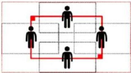 |
| Auto Zoom | WhenAuto Zoomis off, the camera stops zooming in/out automatically but keep the zoom size based on the preset point selected from the drop-down list below. |
| Auto Tilt | Check the box to turn on theAuto Tiltfunction. |
Gesture
The Gesture Control allows you to control certain camera functions with hand gestures. Connect your device to the screen with an HDMI cable.
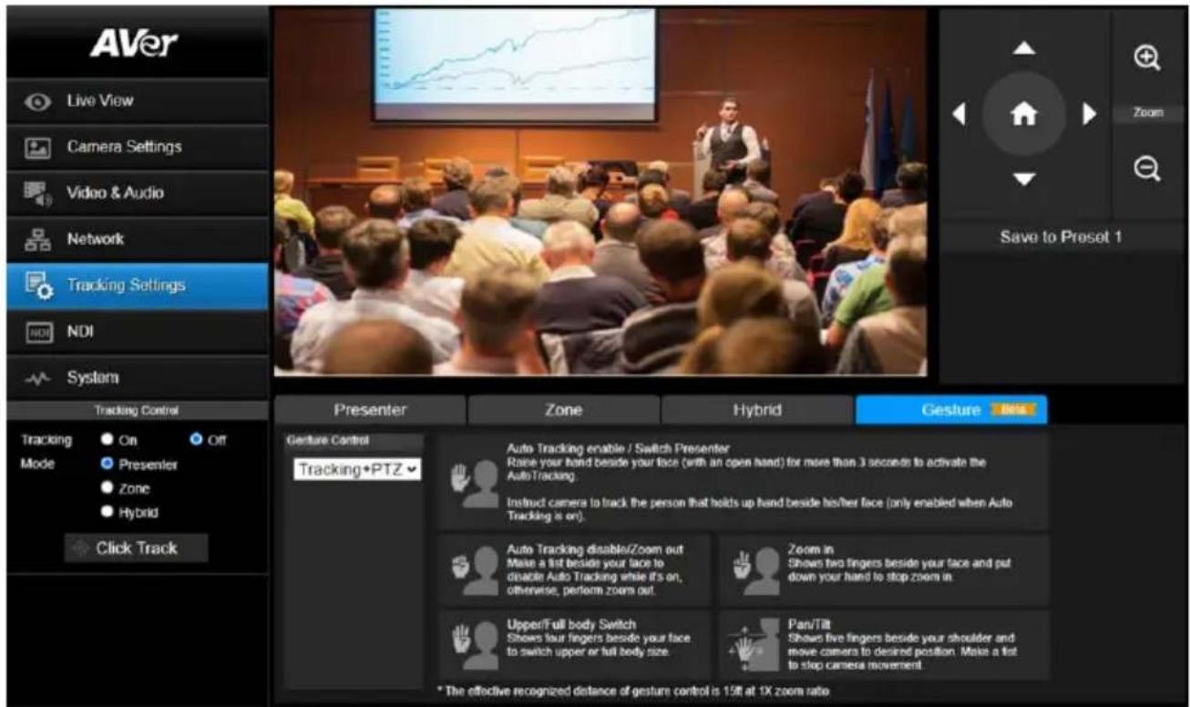
To perform the gesture control function:
- Turn off the Tracking Mode first.
- Ensure the camera has been set up at 1X zoom ratio and the distance between the presenter and the camera is 15ft.
-
On the Gesture Control drop-down list, select an option to turn on the gesture control function.
-
Off: Select to turn off the gesture control function. When Auto Tracking is off, the camera will automatically return to the preset position you choose.
- Tracking: Select to turn on the gesture control functions in the Tracking mode. Gesture functions include turning on or off Auto Tracking and switching people size between full and upper body.
- PTZ: Select to turn on the gesture control functions in the PTZ mode. Gesture functions include zoom in/out and pan/tilt control.
-
Tracking+PTZ: Select to turn on the gesture control functions both in the Tracking and PTZ mode.
-
When the camera recognize the gestures, the LED indicator will blink purple and the system will activate the corresponding functions.
| Gesture | Description |
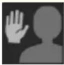 | Auto Tracking enable / Switch PresenterRaise your hand beside your face (with an open hand) for more than 3 seconds to activate the Auto Tracking.Instruct camera to track the person that holds up beside his/her face (only enabled when Auto Tracking is on). |
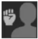 | Auto Tracking disable/ Zoom outMake a fist beside your face to disable Auto Tracking while it's on; otherwise perform zoom out. |
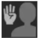 | Upper/Full Body SwitchShows four fingers beside your face to switch upper or full body size. |
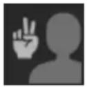 | Zoom InShows two fingers beside your face and put down your hand to stop zoom in. |
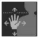 | Pan/TiltShows five fingers beside your shoulder and move camera to desired position.Make a fist to stop camera movement. |
NDI
You can activate the NDI function using this page. Camera firmware version v31 and later supports NDI function.
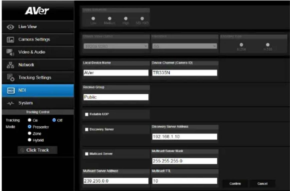
To set up the NDI function:
This camera is compatible with NDI | HX3 of NewTek, Inc. To use NDI | HX3, you are required to purchase the license key from the URL of NewTek, Inc. https://www.newtek.com/ndihx/products/upgrade/
To activate the NDI license key:
- Ensure the camera has been connected to the Internet for NDI License Activation.
- Check whether camera firmware version is v31 or later to support the NDI function.
- On the camera Web page of NDI, click the NDI Activate Function to enter the license key. When finished, click Activate. A message pops up for camera reboot. Click OK to reboot the camera.
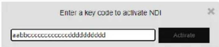
- If success, go to Video & Audio > Video Mode, you will see NDI option on the drop-down list. Select NDI to turn on the NDI function. Please refer to Video Mode in
Configure the below settings and then click Confirm.
| Item | Description |
| Local Device Name | Enter a name of the camera to be shown within NDI devices. For best results, name all AVer cameras the same Local Device Name. e.g. PTZ Cameras or Tracking Cameras. |
| Device Channel (Camera ID) | Enter a channel name for the camera. The default camera name is TR335N.The supported characters are:Numeric characters: 0123456789Alphabetic characters: ABCDEFGHIJKLMNOPQRSTUVWXYZ abcdefghijklmnopqrstuvwxyzSymbols: ! @ % ^ , . / : + ? [ ] { } - _ ~ |
| Receive Group | Enter a name of the receive group. The Receive Group allows you to limit which users on your LAN can see the NDI source. The Receive Group is recommended to remainPublic. Once the Receive Group is changed, you will need to join the Receive Group through NDI® Access Manager. |
| Reliable UDP | Select the checkbox to turn on theUDP protocol. |
| Discovery Server | Select the checkbox to turn onDiscovery Server. Enter the IP address in theDiscovery Server Addresscolumn. |
| Multicast Server | Select the checkbox to turn onMulticast Server. Enter the related info in theMulticast Server Mask and Multicast Server Address columns. You can use theMulticast TTLto adjust the Multicast Time-To-Live interval. |
System
You can view the system information, or configure some system settings on this page.
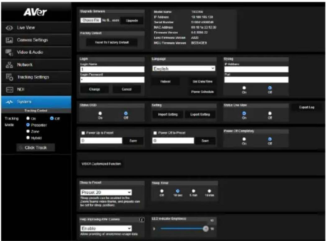
| Item | Description |
| Upgrade firmware | To upgrade the firmware:1. Download the newest firmware fromhttps://www.aver.com/Download-Center/professional-ptz-camera2. On the Web page, go to System > Upgrade firmware.3. Click Choose File to select the firmware.4. Click Upgrade to start upgrading the firmware.5. Refresh the browser after the upgrade process is complete. |
| Factory Default | Click Reset To Factory Default to clear all values and reset the camera back to factory default settings. |
| Camera Information | Displays the camera information. |
| Login | The default Login Name and Login Password are 1/1. To change the login ID and password, enter the new Login Name and Login Password. When finished, click Change. |
| Language | Select a system language from the drop-down list.Click Reboot to reset the setting. |
| Set Date/Time | Click to turn on the Network Time Protocol and select a Time Zone from the drop-down list to automatically synchronize date and time. You can also turn off the NTP and enter date and time manually. |
| Power Schedule | Click to schedule time for powering on/off and Auto Reboot. |
| Syslog | Turn on Syslog to receive technical supports.Enter the IP Address and Port of the receiving device for debug and problem analysis. |
| Status OSD | Turn on or off status info on the live view, including operating the Preset (save preset, call preset and cancel preset), Zoom or Tracking functions. |
| Setting | Click Import Setting to import camera configurations.Click Export Setting to export camera configurations. |
| Status Live View | Click to turn on or off status live view. |
| Power Up to Preset | Select a pre-configured preset position from the drop-down list, the camera will move to the preset position when powered up. |
| Power Off to Preset | Select a pre-configured preset position from the drop-down list, the camera will move to the preset position when powered off. |
| Power Off Completely | ● On: The camera will enter Low Power mode when sleeping and will take more time to wake up and reboot.● Off: To disable the setting above. |
| VISCA Customized Function | Configure the settings and then click OK. |
| Sleep to Preset | Select a pre-configured preset point for the camera to move to when enter the Sleep mode.To turn off Sleep mode, select Off from the drop-down list. |
| Sleep Timer | Set up a duration for the sleep timer. When there is no UVC connection and timer is up, the camera will enter the sleep mode. To perform this function, ensure to select ZOOM or Teams in the Video & Audio > Theme Mode setup field. |
| Help Improving AVer Camera | Select from the drop-down list to set if you allow the providing of anonymous usage data. |
| LED Indicator Brightness | Drag the slider to adjust the brightness value. |
VISCA RS-232 Command Table
| Command Set | Command | Command Packet | Comments |
| CAM_Power | On | 8x 01 04 00 02 FF | Power ON/OFF |
| Off | 8x 01 04 00 03 FF | ||
| CAM_Zoom | Stop | 8x 01 04 07 00 FF | |
| Tele(Variable) | 8x 01 04 07 2p FF | p=0 (Low) to 7 (High) | |
| Wide(Variable) | 8x 01 04 07 3p FF | ||
| Direct | 8x 01 04 47 0p 0q 0r 0s FF | pqrs: Zoom Position ,PTC310: 0x0000~0x6f20PTC330: 0x0110~0x5490 | |
| CAM_Focus | Stop | 8x 01 04 08 00 FF | |
| Far (Standard) | 8x 01 04 08 02 FF | Each 'Far/Near' needs a 'stop' | |
| Near (Standard) | 8x 01 04 08 03 FF | ||
| Auto Focus | 8x 01 04 38 02 FF | ||
| Manual Focus | 8x 01 04 38 03 FF | ||
| One Push | 8x 01 04 18 01 FF | ||
| Direct | 8x 01 04 47 0p 0q 0r 0s FF | pqrs: Zoom Position | |
| CAM_WB | Auto | 8x 01 04 35 00 FF | Normal Auto |
| ATW | 8x 01 04 35 04 FF | ||
| Indoor | 8x 01 04 35 01 FF | ||
| Outdoor | 8x 01 04 35 02 FF | ||
| One Push WB | 8x 01 04 35 03 FF | One Push WB mode | |
| Manual | 8x 01 04 35 05 FF | Manual Control mode | |
| One Push | 8x 01 04 10 05 FF | One Push WB Trigger | |
| CAM_RGain | Up | 8x 01 04 03 02 FF | Manual Control of R Gain |
| Down | 8x 01 04 03 03 FF | ||
| CAM_Bgain | Up | 8x 01 04 04 02 FF | Manual Control of B Gain |
| Down | 8x 01 04 04 03 FF | ||
| CAM_AE | Full Auto | 8x 01 04 39 00 FF | Automatic Exposure mode |
| Manual | 8x 01 04 39 03 FF | Manual Control mode | |
| Shutter Priority | 8x 01 04 39 0A FF | Shutter Priority Automatic Exposure mode | |
| Iris Priority | 8x 01 04 39 0B FF | Iris Priority Automatic Exposure mode | |
| Bright | 8x 01 04 39 0D FF | Bright Mode (Manual control) | |
| CAM_Shutter | Up | 8x 01 04 0A 02 FF | Shutter Setting |
| Down | 8x 01 04 0A 03 FF | ||
| CAM_Iris | Up | 8x 01 04 0B 02 FF | Iris Setting |
| Down | 8x 01 04 0B 03 FF | ||
| CAM_Gain | Up | 8x 01 04 0C 02 FF | Gain Setting |
| Down | 8x 01 04 0C 03 FF | ||
| CAM_Bright | Up | 8x 01 04 0D 02 FF | Bright Setting |
| Down | 8x 01 04 0D 03 FF | ||
| CAM_ExposureCompensation | Up | 8x 01 04 0E 02 FF | Exposure Compensation Amount Setting |
| Down | 8x 01 04 0E 03 FF | ||
| CAM_Backlight | On | 8x 01 04 33 02 FF | Back Light Compensation ON/OFF |
| Off | 8x 01 04 33 03 FF | ||
| CAM_Preset | Reset | 8x 01 04 3F 00 pp FF | pp: Preset Number 0x00~0xFF |
| Set | 8x 01 04 3F 01 pp FF | ||
| Recall | 8x 01 04 3F 02 pp FF | ||
| CAM_Menu | On/Off | 8x 01 06 06 10 FF | Display ON/OFF |
| Pan-tilt Drive | Up | 8x 01 06 01 VV WW 03 01 FF | VV: Pan speed setting 0x01 (low speed) to 0x18 (high speed)WW: Tilt speed setting 0x01 (low speed) to 0x18 (high speed) |
| Down | 8x 01 06 01 VV WW 03 02 FF | ||
| Left | 8x 01 06 01 VV WW 01 03 FF | ||
| Right | 8x 01 06 01 VV WW 02 03 FF | ||
| UpLeft | 8x 01 06 01 VV WW 01 01 FF | ||
| UpRight | 8x 01 06 01 VV WW 02 01 FF | ||
| DownLeft | 8x 01 06 01 VV WW 01 02 FF | ||
| DownRight | 8x 01 06 01 VV WW 02 02 FF | ||
| Stop | 8x 01 06 01 VV WW 03 03 FF | ||
| Home | 8x 01 06 04 FF | ||
| Reset | 8x 01 06 05 FF | ||
| CAM_WDR | On | 8x 01 04 3D 02 FF | Wdr ON/OFF |
| Off | 8x 01 04 3D 03 FF | ||
| CAM_MenuEnter | 8x 01 7E 01 02 00 01 FF | Enter Submenu | |
| Tally Lamp | ON (RED) | 8x 01 7E 01 0A 00 02 FF | |
| OFF | 8x 01 7E 01 0A 00 03 FF | ||
| ON (AMBER) | 8x 01 7E 01 0A 00 04 FF | ||
| ON (GREEN) | 8x 01 7E 01 0A 00 05 FF | ||
| Freeze | Preset Freeze On | 81 01 04 62 22 FF | Freeze On When Running Preset |
| Preset Freeze Off | 81 01 04 62 23 FF | Freeze Off When Running Preset | |
| Auto Tracking | On | 8x 01 04 7D 02 FF | Auto tracking ON/OFF |
| Off | 8x 01 04 7D 03 FF | ||
| CAM_Memory Special | Set | 8x 01 04 3F 01 pp FF | These are changeable depending on VISCA Customized Functions web setting:pp: 0x00 To 0xFF normal presetpp: 0x5F => Turn on OSD menupp: 0xA0 => Full Bodypp: 0xA1 => Upper Bodypp: 0xA2 => Tracking Pointpp: 0xA3 => Switchpp: 0xA4 => Presenter mode (supported in FW v25 or newer)pp: 0xA5 => Zone mode (supported in FW v25 or newer)pp: 0xA6 => Hybrid mode (supported in FW v35 or newer) |
| Absolute Position | Set | 8x 01 06 02 VV WW 0Y 0Y 0Y 0Y 0Z 0Z 0Z 0Z FF | VV: Pan speed setting 0x01 (low speed) to 0x18 (high speed)WW: Tilt speed setting 0x01 (low speed) to 0x18 (high speed)YYYY: Pan PositionZZZZ: Tilt Position |
| Auto zoom | On | 8x 01 04 A0 02 FF | |
| Off | 8x 01 04 A0 03 FF | ||
| Effective Tracking area | On | 8x 01 04 A1 02 FF | |
| Off | 8x 01 04 A1 03 FF | ||
| RTMP | On | 8x 01 04 A2 02 FF | |
| Off | 8x 01 04 A2 03 FF | ||
| Reboot | On | 8x 01 04 A4 FF | |
| On | 8x 01 04 A5 02 FF | ||
| Preset Affects PTZ & Focus Values Only | Off | 8x 01 04 A5 03 FF | |
| Relative Zoom Ratio | On | 8x 01 04 A6 02 FF | |
| Off | 8x 01 04 A6 03 FF | ||
| Auto Tilt | On | 8x 01 04 A7 02 FF | |
| Off | 8x 01 04 A7 03 FF | ||
| Auto Zoom/Tilt preset | Set | 8x 01 04 A8 pp FF | pp: 0x00 To 0xFF normal preset |
| Inquiry Command | Command Packet | Reply Packet | Comments |
| CAM_PowerInq | 8x 09 04 00 FF | y0 50 02 FF | On |
| y0 50 03 FF | Off | ||
| CAM_WBModelnq | 8x 09 04 35 FF | y0 50 00 FF | Auto |
| y0 50 01 FF | In Door | ||
| y0 50 02 FF | Out Door | ||
| y0 50 03 FF | One Push WB | ||
| y0 50 04 FF | ATW | ||
| y0 50 05 FF | Manual | ||
| CAM_RGainInq | 8x 09 04 43 FF | y0 50 00 00 0p 0q FF | pq: R Gain |
| CAM_BGainInq | 8x 09 04 44 FF | y0 50 00 00 0p 0q FF | pq: B Gain |
| CAM_AEmodelnq | 8x 09 04 39 FF | y0 50 00 FF | Full Auto |
| y0 50 03 FF | Manual | ||
| y0 50 0A FF | Shutter Priority | ||
| y0 50 0B FF | Iris Priority | ||
| y0 50 0D FF | Bright | ||
| CAM_ShutterPosInq | 8x 09 04 4A FF | y0 50 00 00 0p 0q FF | pq: Shutter Position |
| CAM_IrisPosInq | 8x 09 04 4B FF | y0 50 00 00 0p 0q FF | pq: Iris Position |
| CAM_GainPosInq | 8x 09 04 4C FF | y0 50 00 00 0p 0q FF | pq: Gain Position |
| CAM_BrightPosInq | 8x 09 04 4D FF | y0 50 00 00 0p 0q FF | pq: Bright Position |
| CAM_ExpCompPosInq | 8x 09 04 4E FF | y0 50 00 00 0p 0q FF | pq: ExpComp Position |
| CAM_FocusModelnq | 8x 09 04 38 FF | y0 50 02 FF | Auto Focus |
| y0 50 03 FF | Manual Focus | ||
| CAM_FocusPosInq | 8x 09 04 48 FF | y0 50 0p 0q 0r 0s FF | pqrs: Focus Position |
| zoom_Pos_Inq | 8x 09 04 47 FF | y0 50 0p 0q 0r 0s FF | pqrs: Zoom Position |
| PT_Pos_Inq | 8x 09 06 12 FF | y0 50 0Y 0Y 0Y 0Z 0Z 0Z 0Z FF | YYYY: Pan Position 8A14 to 762C (CENTER 0000)ZZZZ: Tilt Position 468B to E898 (Image Flip: OFF)(CENTER 0000) |
| CAM_Preset Inq | 8x 09 04 3F FF | y0 50 pp FF | Return the last preset number which has been operatedpp:01-FF |
| CAM_Tracking status | 8x 09 36 69 02 FF | y0 50 01 FF | On |
| y0 50 00 FF | Off | ||
| CAM_Tracking_mode | 8x 09 36 69 01 FF | y0 50 01 FF | Presenter |
| y0 50 02 FF | Zone | ||
| y0 50 03 FF | Hybrid | ||
| CAM_Tracking body size | 8x 09 36 69 03 FF | y0 50 01 FF | Full body |
| y0 50 02 FF | Upper body | ||
| CAM_OSD MENU on/off | 8x 09 7E 04 76 01 FF | y0 50 02 FF | On |
| y0 50 03 FF | Off | ||
| CAM_Tally | 8x 09 7E 01 0A FF | y0 50 02 FF | On |
| y0 50 03 FF | Off | ||
| CAM_WDR mode | 8x 09 04 3D FF | y0 50 02 FFy0 50 03 FF | OnOff |
| CAM_BLC mode | 8x 09 04 33 FF | y0 50 02 FF | On |
| y0 50 03 FF | Off | ||
| CAM_Live Freeze | 8x 09 04 62 01 FF | y0 50 02 FF | Freeze On |
| y0 50 03 FF | Freeze Off | ||
| CAM_Preset Freeze | 8x 09 04 62 02 FF | y0 50 02 FF | Preset Freeze On |
| y0 50 03 FF | Preset Freeze Off | ||
| Firmware version | 8x 09 36 69 04 FF | y0 50 0p 0q 0r 0s 0t 0u 0v 0w FF | fw_ver: p.q.rstu.vw |
| USB Status | 8x 09 36 69 05 FF | y0 50 00 FF | USB cable plug out |
| y0 50 01 FF | USB cable plug in | ||
| UVC Status | 8x 09 36 69 06 FF | y0 50 00 FF | UVC stream off |
| y0 50 01 FF | UVC stream on |
Visca over IP Settings
VISCA over IP
PORT
| Internet protocol | IPv4 |
| Transport protocol | UDP |
| Port address | 52381 |
FORMAT
| byte 0 | byte 1 | byte 2 | byte 3 | byte 4 | byte 5 | byte 6 | byte 7 | bytes **** byte23 | |
| func | Payload type | Payload length | Sequence number | Payload (1 to 16 bytes) | |||||
| data | Value1 | Value2 | t-16 pixels-t-0000 | 0X00000000 ~ 0X0FFFFFFF | VISCA Packet (see page VISCA) | ||||
Payload type
| Name | Value1 | Value2 | Description |
| VISCA command | 0x01 | 0x00 | Stores the VISCA command. |
| VISCA inquiry | 0x01 | 0x10 | Stores the VISCA inquiry. |
| VISCA reply | 0x01 | 0x11 | Stores the reply for the VISCA command or VISCA inquiry |
Sequence number
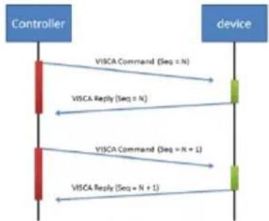
flowchart
graph TD
    A["Controller"] -->|VISCA Command (Seq = N)| B["device"]
    B -->|VISCA Reply (Seq = N)| A
    A -->|VISCA Command (Seq = N + 1)| B
    B -->|VISCA Reply (Seq = N + 1)| A
Sequence number = N
CGI Command
| CGI List for Video Transmission | |||||
| CGI Item name | URL | Command | Parameter Name | Parameter value | Description |
| Get JPEG | /snapshot | 1280x720 jpg | |||
| Get RTSP stream | rtsp://ip/live_st1 | ||||
| CGI List for Camera Control | |||||
| CGI item name | URL | Command | Parameter Name | Parameter value | Description |
| up start | /cgi-bin?SetPtzf= | 1,0,1&(random) | |||
| up end | /cgi-bin?SetPtzf= | 1,0,2&(random) | |||
| down start | /cgi-bin?SetPtzf= | 1,1,1&(random) | |||
| down end | /cgi-bin?SetPtzf= | 1,1,2&(random) | |||
| left start | /cgi-bin?SetPtzf= | 0,1,1&(random) | |||
| left end | /cgi-bin?SetPtzf= | 0,1,2&(random) | |||
| right start | /cgi-bin?SetPtzf= | 0,0,1&(random) | |||
| right end | /cgi-bin?SetPtzf= | 0,0,2&(random) | |||
| zoom_in start | /cgi-bin?SetPtzf= | 2,0,1&(random) | |||
| zoom_in end | /cgi-bin?SetPtzf= | 2,0,2&(random) | |||
| zoom_out start | /cgi-bin?SetPtzf= | 2,1,1&(random) | |||
| zoom_out end | /cgi-bin?SetPtzf= | 2,1,2&(random) | |||
| set preset: | /cgi-bin?ActPreset= | 1,N&(random) | N : position | ||
| load preset: | /cgi-bin?ActPreset= | 0,N&(random) | N : position | ||
| set preset speed | /cgi-bin?Set=preset_speed,3,val | val: {min: 1, max: 6} | |||
| Absolute Position (Pan) | /cgi-bin?Set=ptz_p,3,val | val: {min: 2048, mid: 962944, max: 1925888} | Follows CGI preset speed | ||
| Absolute Position (Tilt) | /cgi-bin?Set=ptz_1,3,val | val: {min: 2048, mid: 165696, max: 662784} | Follows CGI preset speed | ||
| Absolute Position (Zoom) | /cgi-bin?Set=ptz_z,3,val | val: {min: 2048, mid: 14224, max: 28448} | Follows CGI preset speed | ||
| CGI List for Various Settings | |||||
| exposure value | /cgi-bin?Set= | img_expo_expo,3,N&(random) | value | 1 ~ 9 | N : value |
| saturation | /cgi-bin?Set= | img_saturation,3,N&(random) | value | 0 ~ 10 | N : value |
| contrast | /cgi-bin?Set= | img_contrast,3,N&(random) | value | 0 ~ 4 | N : value |
| Tracking on: | /cgi-bin?Set= | trk_tracking_on,3,1 | |||
| Tracking off: | /cgi-bin?Set= | trk_tracking_on,3,0 | |||
| Reboot | GET(Basic Authentication) | /cgi-bin?OnePush=! | |||
| Factory Reset | GET(Basic Authentication) | /cgi-bin?OnePush=d | |||
| Mode Presenter | /cgi-bin?Set=trk_mode,3,1&X | value | random number | X : value | |
| Mode Zone | /cgi-bin?Set=trk_mode,3,2&X | value | random number | X : value | |
| Mode Hybrid | /cgi-bin?Set=trk_mode,3,3&X | ||||
| Mode Get | GET(Basic Authentication) | /cgi-bin?Get=trk_mode.3&_X | - Reply | Presentertrk_mode,3=1Zonetrk_mode,3=2Hybridtrk_mode,3=3 | X : value |
| Click Track ON | GET(Basic Authentication) | /cgi-bin?Set=trk_update_detect,3,1 | |||
| Click Track OFF | GET(Basic Authentication) | /cgi-bin?Set=trk_update_detect,3,0 | |||
| Click Track Get detect zone (Humanoid outlines) number | GET(Basic Authentication) | /cgi-bin?Get=trk_detect_num,3 | Need to be sent along with Click Track ON command | ||
| - Reply | "trk_detect_num,3=X\r\n" | X: The amount of humanoid outlines, maximum: 50 | |||
| Click Track Get detect zone (Humanoid outlines) info | GET(Basic Authentication) | /cgi-bin?GetTrackingDetectZone=X | X: The amount of humanoid outlines, maximum: 50 | ||
| - Reply | "focus:-1\nzone[00]:00,119,720,960\nzone[01]:-1502615204,-1366225632,01,-1366223544" | focus - The number of humanoid outline being tracked.zone[NN]:x,y,w,h - based on 1080P resolution | The upper left corner of the screen is the coordinate reference (0,0), x-coordinate/y-coordinate/w width/h height, based on the upper left corner of the humanoid outline.The number following indicates the number of the tracked person, for example,-1 means that no one is being tracked. If one of the three is being tracked, one of 0, 1 and 2 will appear after the 'focus'. | ||
| Click Track Set target zone | GET(Basic Authentication) | /cgi-bin?Set=trk_assign_zone,3,X | X: The number of the human outlines | ||
| - Reply | http response: ok | ||||
| GET(Basic Authentication) | /cgi-bin?SetString=TrackingFocusZone,[x.y.w,h] | ||||
| - Reply | http response: ok | ||||
| Tracking On/Off Get | GET(Basic Authentication) | /cgi-bin?Get=trk_tracking_on,3&_X | - Reply | Ontrk_tracking_on,3=1Offtrk_tracking_on,3=0" | X : value |
| RTMP Start streamming | /cgi-bin?Set= | vdo_rtmp_enable,3,1 | |||
| RTMP Stop streamming | /cgi-bin?Set= | vdo_rtmp_enable,3,0 | |||
| USB status | GET(Basic Authentication) | /cgi-bin?Get=usb_status_inquire,3 | |||
| - Reply | "usb_status_inquire,3=X\r\n" | X: 0(plug out), 1(plug in) | |||
| UVC status | GET(Basic Authentication) | /cgi-bin?Get=uvc_status_inquire,3 | |||
| - Reply | "uvc_status_inquire,3=X:\n" | X: 0(stream off), 1(stream on) | |||
| Status get (Modle name & mac & FW_VER) | /cgi-bin?GetString=sys_name &net_mac&sys_fw_version&_=1635216271678 | http://10.100.105.110/cgi-bin?GetString=sys_name&net_mac&sys_fw_version&_=1635216271678 | |||
| Serial No. get | /cgi-bin?GetSerialNumber&_=1635216271680 | http://10.100.105.110/cgi-bin?GetSerialNumber&_=1635216271680 | |||
| script(Using cURL to update firmware) | curl.exe -X POST --user NAME:PASSWORD -F file1=@./ISP_FILE "http://IP_ADDRESS/system/" | Please download curl (curl for Windows), this is a command line tool for network transferring.Put curl.exe and ISP file in the same folder. and then execute the script to upgrade camera.For example, ISP file is 0.0.0000.29.dat, IP address is 10.100.105.109 and username:password is 1:1, you can enter this script to execute ISP process.curl.exe -X POST --user 1:1 - F file1=@./0.0.0000.29.dat "http://10.100.105.109/system/" | |||
Pelco P Command
PTC300V2 Pelco-P command
| PAN AND TILT COMMANDS | P/T bit(byte4.0) = 0 | |||||||
| byte 1 | byte 2 | byte 3 | byte 4 | byte 5 | byte 6 | byte 7 | byte 8 | |
| func | STX | ADDR | data1 | data2 | data3 | data4 | ETX | checksum |
| data | 0xA0 | 0~7F | cmd 1 | cmd 2 | Fan speed | Tilt speed | 0xAF | 1~7 XOR |
note : speed = 0x00\~0x30
byte3: command 1
| bit 7 | bit 6 | bit 5 | bit 4 | bit 3 | bit 2 | bit 1 | bit 0 |
| NA | CAMON | NA | CAMON/OFF | NA | NA | NA | NA |
note : power off : byte3.6 = 0 & byte3.4 = 1
byte4: command 2
| bit 7 | bit 6 | bit 5 | bit 4 | bit 3 | bit 2 | bit 1 | bit 0 |
| NA | ZOOMWide | ZOOMTele | TILTDown | TILTUp | PANLeft | PANRight | P/T bit0(always) |
EXTENDED COMMAND SET
P/T bit(byte4.0) = 1
| byte 1 | byte 2 | byte 3 | byte 4 | byte 5 | byte 6 | byte 7 | byte 8 | ||
| func | STX | ADDR | data1 | data2 | data3 | data4 | ETX | checksum | |
| Set Preset XX | 0xA0 | 0~7 | 0x00 | 0x03 | 0x00 | Preset # | 0xAF | 1~7 XOR | |
| Go To Preset XX | 0xA0 | 0~7 | 0x00 | 0x07 | 0x00 | Preset # | 0xAF | 1~7 XOR | |
| Track ON | 0xA0 | 0~7 | 0x00 | 0x65 | 0x00 | 0x00 | 0xAF | 1~7 XOR | |
| Track OFF | 0xA0 | 0~7 | 0x00 | 0x67 | 0x00 | 0x00 | 0xAF | 1~7 XOR | |
note : Preset # : 0x01 \~ 0xFF
Profile #: 0x01 \~ 0x05
Pelco D Command
pelco d command
PAN AND TIC COMMANDS
P/T bit|byte=4.0| = 0
| byte 1 | byte 2 | byte 3 | byte 4 | byte 5 | byte 6 | byte 7 | |
| func | SYNC | ADDR | cmd 1 | cmd 2 | data1 | data2 | checksum |
| data | 0diff | 1"80 | cmd 1 | cmd 2 | Pan spend | Tilt speed | 2"6 SUM |
note speed = 0x00' 0x30
byte1 : command 1
| bit 2 | bit 6 | bit 5 | bit 4 | bit 3 | bit 2 | bit 1 | bit 0 |
| SENSE | CAM | ||||||
| ON | NA | NA | NA | ON/OFF | NA | NA | NA |
note: power off: byte3.7 = 0 & byte3.3 = 1
byte4 command 2
| bit 7 | bit 6 | bit 5 | bit 4 | bit 3 | bit 2 | bit 1 | bit 0 |
| NA | ZOOMWide | ZOOMTide | TIETDown | TIETUp | PANLeft | PANRight | P/T (bit0(always) |
EXTENDED COMMAND SET
P/T (bit[byte-6.0]) = 1
| Byte 1 | Byte 2 | Byte 3 | Byte 4 | Byte 5 | Byte 6 | Byte 7 | |
| Func | SYNC | ADDR | data1 | data2 | data3 | data4 | checksum |
| Set Preset XX | 0xFF | 1~8 | 0x00 | 0x03 | 0x00 | Preset # | 2~5 SUM |
| Go To Preset XX | 0xFF | 1~8 | 0x00 | 0x07 | 0x00 | Preset # | 2~5 SUM |
| Track ON | 0xFF | 1~8 | 0x00 | 0x05 | 0x00 | 0x00 | 2~5 SUM |
| Track OFF | 0xFF | 1~8 | 0x00 | 0x07 | 0x00 | 0x00 | 2~5 SUM |
note: Preset #: 0x01\~0x49
Example:
Camera Address: 1
Pan Left at high speed: FF 01 00 (4 3F 00 44
Pan Right at medium speed. FF 01 00 02 20 00 23
Tilt Up at high speed: FF 01 00 08 00 3F 48
Tilt Down at medium speed: FF 01 00 10 20 00 31
Stop all actions (Pan / Tilt / Zoom / Ms etc.) FF 01 00 00 00 00 01
- AI Auto Tracking PTZ Camera
- Federal Communications Commission
- Warning
- Remote Control Battery Safety Information
- DISCLAIMER
- TRADEMARKS
- COPYRIGHT
- NOTICE
- More Help
- Headquarters
- USA Branch office
- Europe Branch office
- Contact Information
- Japan Branch Office
- Vietnam Branch Office
- Product Introduction .... 4
- Device Connection....9
- Camera Installation....20
- Set Up the Camera 23
- Web Setup....30
- Appendix....61
- Package Contents
- Optional Accessories
- Product Introduction
- Overview
- Dimensions
- Pan and Tilt Angle
- PoE Connection
- RS-232 and RS-422 Connection
- ● Din8 to D-Sub9 Cable Pin Definition
- Audio Input Connection
- [Notes]
- Video Output Connection
- • HDMI
- - 3G-SDI
- Cable Fixing Plate Installation
- Ceiling Mount Installation
- Camera Installation
- Remote Control
- Set Up the Camera
- OSD Menu
- IP Address Setup
- Static IP
- DHCP
- OSD Menu Tree
- Camera
- V3 Series
- Video Output
- Network
- System
- Access the Web Interface of the Camera
- Access the Camera via AVer IPCam Utility
- To use AVer IPCam Utility to find the camera IP address:
- Accessing the Camera via AVer PTZ Management
- Live View
- Camera Control
- ● Pan-Tilt-Zoom Control
- Preset
- To set up preset positions:
- To move camera to preset positions:
- To customize camera functions at each preset positions:
- Camera Settings
- Exposure
- Image Process
- Video & Audio
- - SRT Settings
- Example 1 vMix:
- Example2 OBS (Open Broadcaster Software):
- Tracking Settings
- To perform the tracking function, you can:
- Presenter Mode
- Configuring Multi-Presenter Detection
- To configure Multi-Presenter Detection:
- Zone Mode
- To configure the preset areas:
- Hybrid Mode
- To set up the Tracking Point:
- Gesture
- To perform the gesture control function:
- NDI
- To set up the NDI function:
- To activate the NDI license key:
- Visca over IP Settings
- Pelco P Command
- Pelco D Command
Brand : AVer
Model : TR315N
Category : Security Camera