FD2000 - Security Camera AVer - Free user manual and instructions
Find the device manual for free FD2000 AVer in PDF.


| Product Type | Security Camera |
| Brand | AVer |
| Model | FD2000 |
| Power Supply | DC 12V, 2A |
| Image Sensor | 2MP CMOS (1920x1080) |
| Video Compression | H.264, MPEG4, MJPEG |
| Max Resolution | 1920x1080 @ 30 fps |
| Streaming | Triple streams (H.264, MPEG4, MJPEG) |
| Audio | Built-in mic, support G.711, G.726, AAC |
| Storage | microSD card slot (up to 32GB? Not specified) |
| Network | Ethernet, IPv4/IPv6, DHCP, Static IP, PPPoE |
| Network Protocols | HTTP, HTTPS, RTSP, UPnP, DDNS, SNMPv1/v2/v3, QoS |
| Security | IP filter, 802.1X, RTSP authentication |
| Image Adjustment | White balance, brightness, contrast, saturation, sharpness, flicker control |
| Wide Dynamic Range | WDR (3 levels) |
| Denoise | 2D, 3D, Auto |
| Privacy Mask | 3 regions |
| Intelligent Video Analytics | Motion detection, cross line detection, tampering, missing object, suspicious object |
| ePTZ | Digital pan, tilt, zoom; preset patrol |
| I/O Ports | DIDO & Audio cable, RJ45 |
| Mounting | Wall mount (screws and anchors included) |
| Operating Temperature | Not specified |
| Certifications | FCC Class A, CE |
| Package Contents | Camera, software CD, alignment sticker, screws, anchors, DIDO & Audio cable, RJ45 header, power plug, power adapter |
Frequently Asked Questions - FD2000 AVer
User questions about FD2000 AVer
0 question about this device. Answer the ones you know or ask your own.
Ask a new question about this device
Download the instructions for your Security Camera in PDF format for free! Find your manual FD2000 - AVer and take your electronic device back in hand. On this page are published all the documents necessary for the use of your device. FD2000 by AVer.
USER MANUAL FD2000 AVer
This device complies with Part 15 of the FCC Rules. Operation is subject to the following two conditions: (1) this device may not cause harmful interference, and (2) this device must accept any interference received, including interference that may cause undesired
operation.
Federal Communications Commission Statement
NOTE- This equipment has been tested and found to comply with the limits for a Class A digital device, pursuant to Part 15 of the FCC Rules. These limits are designed to provide reasonable protection against harmful interference in a residential installation. This equipment generates uses and can radiate radio frequency energy and, if not installed and used in accordance with the instructions, may cause harmful interference to radio communications. However, there is no guarantee that interference will not occur in a particular installation. If this equipment does cause harmful interference to radio or television reception, which can be determined by tuning the equipment off and on, the user is encouraged to try to correct the interference by one or more of the following measures:
● Reorient or relocate the receiving antenna.
- Increase the separation between the equipment and receiver.
- Connect the equipment into an outlet on a circuit different from that to which the receiver is connected.
- Consult the dealer or an experienced radio/television technician for help.
Class A ITE
Class A ITE is a category of all other ITE which satisfies the class A ITE limits but not the class B ITE limits. Such equipment should not be restricted in its sale but the following warning shall be included in the instructions for use:
Warning -This is a class A product. In a domestic environment this product may cause radio interference in which case the user may be required to take adequate measures.
European Community Compliance Statement (Class A)

This product is herewith confirmed to comply with the requirements set out in the Council Directives on the Approximation of the laws of the Member States relating to Electromagnetic Compatibility Directive 2004/108/EC.
Warning - This is a Class A product. In a domestic environment this product may cause radio interference in which case the user may be required to take adequate measures to correct this interference.
COPYRIGHT
© 2015 AVer Information Inc. All rights reserved.
All rights of this object belong to AVer Information Inc. Reproduced or transmitted in any form or by any means without the prior written permission of AVer Information Inc. is prohibited. All information or specifications are subject to change without prior notice.
Trademark
“AVer” is a trademark owned by AVer Information Inc. Other trademarks used herein for description purpose only belong to each of their companies.
NOTICE
SPECIFICATIONS ARE SUBJECT TO CHANGE WITHOUT PRIOR NOTICE. THE INFORMATION CONTAINED HEREIN IS TO BE CONSIDERED FOR REFERENCE ONLY.
WARNING
TO REDUCE RISK OF FIRE OR ELECTRIC SHOCK, DO NOT EXPOSE THIS APPLIANCE TO RAIN OR MOISTURE. WARRANTY VOID FOR ANY UNAUTHORIZED PRODUCT MODIFICATION.
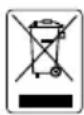
THE MARK OF CROSSED-OUT WHEELED BIN INDICATES THAT THIS PRODUCT MUST NOT BE DISPOSED OF WITH YOUR OTHER HOUSEHOLD WASTE. INSTEAD, YOU NEED TO DISPOSE OF THE WASTE EQUIPMENT BY HANDING IT OVER TO A DESIGNATED COLLECTION POINT FOR THE RECYCLING OF WASTE ELECTRICAL AND ELECTRONIC EQUIPMENT. FOR MORE INFORMATION ABOUT WHERE TO DROP OFF YOUR WASTE EQUIPMENT FOR RECYCLING, PLEASE CONTACT YOUR HOUSEHOLD WASTE DISPOSAL SERVICE OR THE SHOP WHERE YOU PURCHASED THE PRODUCT.
Table of Contents
IMPORTANT SAFEGUARD....1
PACKAGE CONTENTS....2
IP CAMERA INSTALLATION....3
INSERT MICROSD CARD 4
EXTERNAL AUDIO CABLE INSTALLATION....5
LIVE VIEW....6
SYSTEM > GENERAL 8
SYSTEM > GENERAL > MAINTENANCE....8
TO UPGRADE THE IP CAMERA FIRMWARE....9
SYSTEM > GENERAL > DATE & TIME....10
SYSTEM > GENERAL > SYSTEM LOG 11
SYSTEM > USER MANAGEMENT ....12
SYSTEM > USER MANAGEMENT > ACCOUNT....12
TO CREATE A USER ACCOUNT....12
TO DELETE OR EDIT A USER ACCOUNT....13
SYSTEM > USER MANAGEMENT > CONNECTION....14
SYSTEM > NETWORK 15
SYSTEM > NETWORK > SETTING....15
SYSTEM > NETWORK > SERVER....17
SYSTEM > NETWORK > STREAMING ....18
SYSTEM > NETWORK > QoS 19
SYSTEM > NETWORK > OTHERS ....20
SYSTEM > SECURITY 22
SYSTEM > SECURITY > IP FILTER....22
TO ADD FILTER....22
SYSTEM > SECURITY > 802.1X ....24
SYSTEM > SECURITY > RTSP AUTH....25
SYSTEM > IMAGE....26
SYSTEM > IMAGE > OSD 26
SYSTEM > IMAGE > PREFERENCE....27
SYSTEM > IMAGE > EXPOSURE ....28
SYSTEM > IMAGE > ADVANCED....30
SYSTEM > IMAGE > PRIVACY MASK ....31
SYSTEM > VIDEO STREAM > STREAM SETTING....32
APPLICATION > IVA....39
Application > IVA > Cross Detection 40
Application > IVA > Tampering ....41
Application > IVA > Missing Object 42
Application > IVA > Suspicious Object....43
APPLICATION > EPTZ....44
TO SETUP THE EPTZ 44
EVENT SETTING 46
TO SETUP THE EVENT 46
STATUS INFORMATION ....50
GOVERNING LAW AND YOUR RIGHTS ....52
Important Safeguard
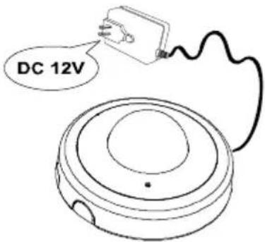
Do not use power supply with different voltage other than DC 12V.
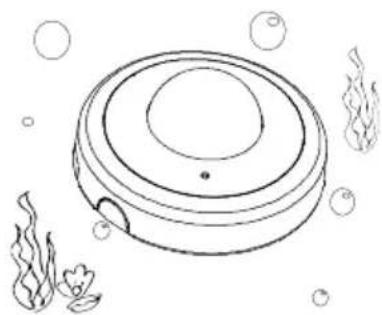
natural_image
Simple line drawing of a vacuum cleaner with bubbles and underwater elements (no text or symbols)Do not submerge the unit in the water.
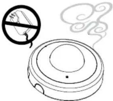
natural_image
Simple line drawing of a vacuum cleaner with smoke and a no-smoking symbol (no text or labels)Unplug the power of this unit as soon as smoke or unusual odor is detected.
natural_image
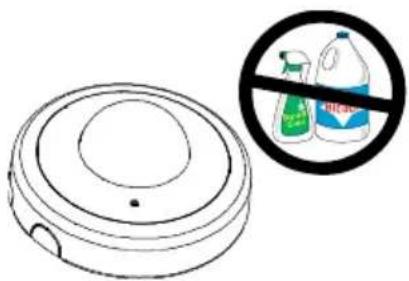
Illustration of a vacuum cleaner with a prohibition symbol (no text or labels)Unplug the power supply before cleaning. Use only a lens cleaning cloth and never use benzene, thinner, or other solvent for cleaning.
natural_image
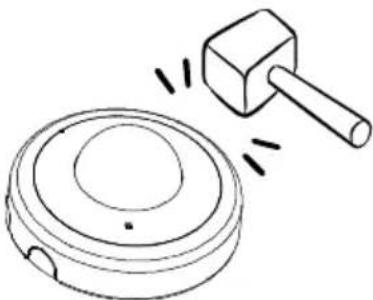
Simple line drawing of a hammer striking a circular object with a base, no text or symbols presentDo not attempt to service this unit by yourself. Always refer all servicing to qualified service personnel.
natural_image
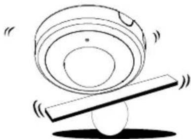
Simple line drawing of a balance scale with a circular object on top and a ball on the side (no text or symbols)Do not place the unit in unsteady surface and also do not drop the unit.

natural_image
Simple line drawing of a spray bottle emitting vapor and a circular container with bubbles (no text or symbols)Keep the IP camera housing close and prevent the dust from getting in the housing.
Package Contents
The following items are included in the package.
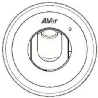
AVer Dome type Camera
natural_image
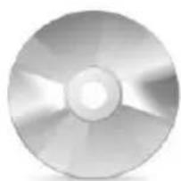
Close-up of a metallic CD or DVD disc with visible blades and central hole (no text or symbols)Software & Manual CD
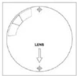
Alignment Sticker
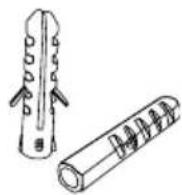
2 Plastic Anchors

Screw
natural_image
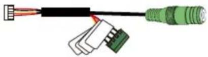
Diagram of a cable connector with three colored wires (black, white, green) and connectors, no text or symbols present.DIDO & Audio cable
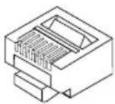
RJ45 header

Power plug**
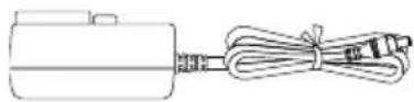
Power Adapter (12V, 2A)
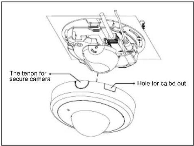
IP Camera Installation
- Place the sticker on the wall surface. Then spot the mark and drill the holes indicated on the sticker.
- Press both side of tenon to open the cover case of the camera.
- Use the plastic anchors to secure the camera on the wall.
- Connect the power cable and Ethernet cable to the camera.
- Loose the screw of lens to adjust the focus. After adjusting, screw the lens tight.
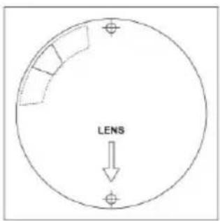
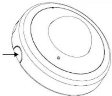
natural_image
Simple line drawing of a circular object with concentric rings and a small arrow pointing to the bottom-left corner (no text or symbols)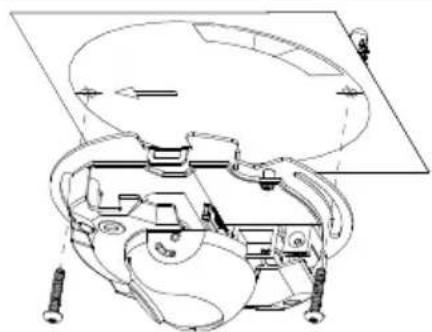
natural_image
Technical line drawing of a mechanical assembly with springs and components (no text or symbols)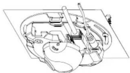
natural_image
Technical line drawing of a mechanical assembly with no visible text or symbols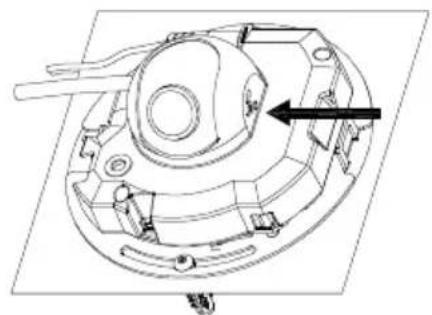
natural_image
Technical line drawing of a mechanical component with no visible text or symbols- Close the cover case of the camera as figure shown.
Insert microSD Card
- Press both side of tenon to open the cover case of the camera.
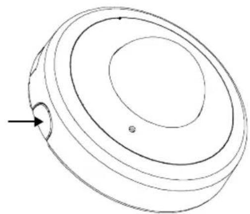
natural_image
Technical line drawing of a circular mechanical component with concentric layers and a small protrusion (no text or symbols)- Insert microSD card
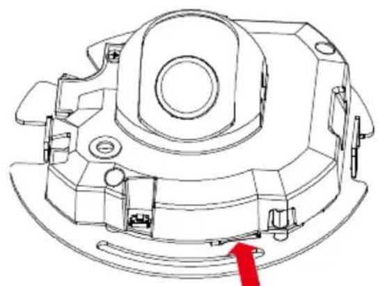
natural_image
Technical line drawing of a mechanical component with no visible text or symbolsInsert microSD card
External Audio Cable Installation
- Press both side of tenon to open the cover case of the camera.
- Connect the external audio cable to the camera.
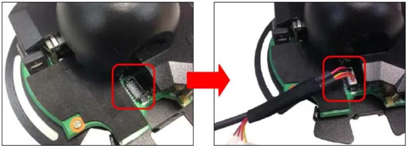
natural_image
Close-up of a device showing a circuit board being inserted into a black plastic housing, with a red arrow indicating the process (no text or symbols visible)- Finally, close camera case cover and secure it.
Using the IP Camera Browser Interface
The admin have the full access to the IP camera browser interface. The menu on the left, you can expand and navigate to access all the features.
Open the IE browser and enter the IP address of IP camera to access the IP camera Web configuration interface. In login dialog, enter the ID and Password (default is admin/admin).
Live View
In the Live View page, all three user levels can view and change the language setting, the IP camera video stream setting, use the digital Pan and Patrol control, capture screen shot, record video, turn on/off 2-way talk, mic and volume, and adjust the zoom and volume level.
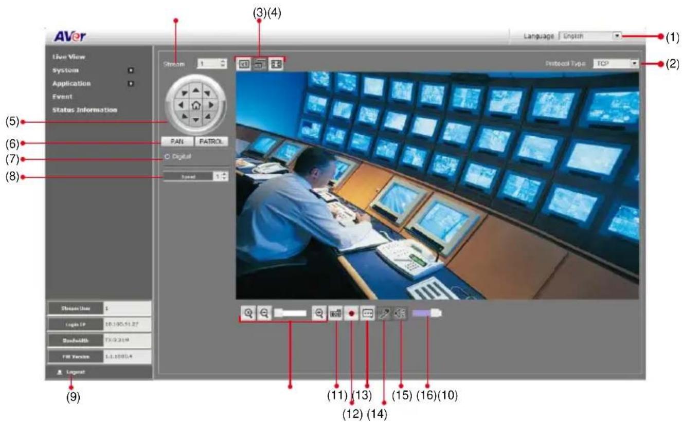
| Name | Function |
| (1) Language | Select the browser interface language. |
| (2) Protocol Type | Select the protocol for the live view video stream. |
| (3) Video screen | Change the video screen display. |
 Display the actual video pixel size. Display the actual video pixel size. | |
 Display the video screen in compact size. Display the video screen in compact size. | |
 Display the video on the entire screen. Press ESC to exit full screen mode. Display the video on the entire screen. Press ESC to exit full screen mode. | |
| (4) Stream | Switch to view the video stream type. The IP camera can send multiple video streams of up to 3 types. To change the video stream setting, go to System > Video Stream. |
| (5) Direction buttons | - Use to move the position of the view point while in zoom mode. - Use to control the position of the RS-485 pan tilt device |
| (6) Pan & Patrol button | Pan: automatically move the view point from left to right when in zoom in mode. Patrol: automatically move the view point around the preset locations in Application > Patrol. |
| (7) Digital | To control the IP camera ePTZ operation. This allows you to closely view the target area without having to physically move the IP camera. The image will be zoomed in and you can use the direction control to pan the zoomed image. |
| (8) Speed control | Set the speed when panning, tilting, or zooming. |
| (9) Logout | Click it to exit the camera connection. |
| (10) Zoom control |  Reset zoom level. Reset zoom level. |
 Increase zoom level. Increase zoom level. | |
 Decrease zoom level. Decrease zoom level. | |
| (11) Capture | Capture and save the image on the screen in *.bmp format. |
| (12) Record |  Start/stop audio and video recording. The recorded video will be saved in *.mp4 format. Start/stop audio and video recording. The recorded video will be saved in *.mp4 format. |
| (13) 2-way talk | [8ZZ5] Enable/disable mic from IP camera browser side. |
| (14) Mic |  Enable/disable mic from the IP camera side. Enable/disable mic from the IP camera side. |
| (15) Sound |  Enable/disable audio from the IP camera side. Enable/disable audio from the IP camera side. |
| (16) Volume bar | Adjust the volume. |
System > General
In this section, only admin level is authorized to configure the IP camera general settings. There are 3 tabs in General settings: Maintenance, Date & Time, and System Log.
System > General > Maintenance
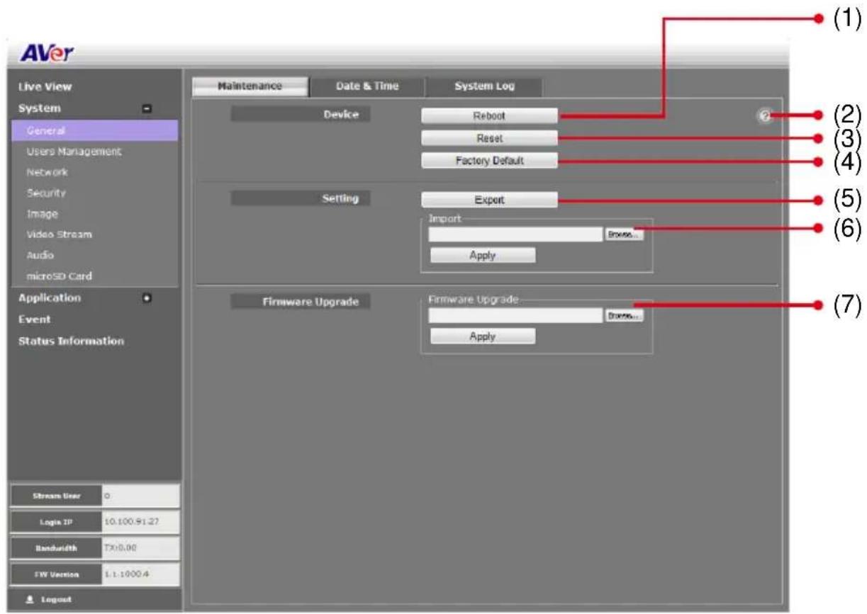
In the Maintenance tab, the admin can easily backup and restore the IP camera setting, reboot the IP camera, reset all the settings to factory default, and upgrade the IP camera firmware.
| Name | Function |
| (1) Reboot | Restart the IP camera. |
| (2) Information | Displays the explanation of Reboot, Reset, and Factory default. |
| (3) Reset | Set all the configuration settings back to default except the user management and network settings. |
| (4) Factory Default | Set all the configuration settings back to factory default. |
| (5) Export Settings | Backup all the configuration settings. |
| (6) Import Settings | Restore or replace the current settings with the backup file. |
Name
Function
(7) Firmware Upgrade
Upgrade the firmware to the latest version.
To Upgrade the IP Camera Firmware
- Download the file from our website and save it in your computer hard disk.
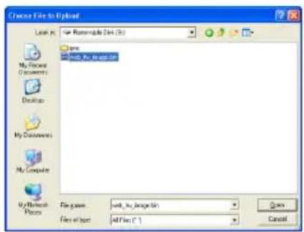
- Click Browse. Locate and select the file and click Open.
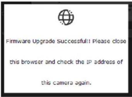
- Click Apply. Wait till you see the massage "Firmware
Upgrade OK!!". You may now click the IE browser refresh button or press F5. The login page will appear.
System > General > Date & Time
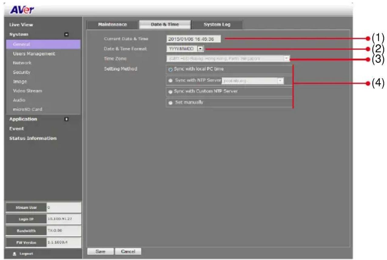
In the Date & Time tab, admin can manually set the date and time setting or synchronize it with the Internet time server or the computer date and time setting. This is used to record the time whenever there is a significant occurrence listed in system log and is also used in event scheduling. After completing the setting, click Save to apply the new setting and Cancel to keep the old setting.
| Name | Function |
| (1) Current Date & Time | Display the current date and time setting. |
| (2) Date Format | Select the date display format. |
| (3) Time Zone | Set the local time zone. |
| (4) Setting Method | Select the date & time setting method.Sync with local PC time: obtain the date and time setting on the current login computer.Sync with NTP Server: obtain the date and time setting from NTP server. In the drop-down list, select the NTP host name.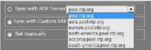 Sync with Custom NTP Server: Enter the IP address of NTP server manually.○ Sync with Custom NTP Server 192.168.1.1Set Manual: manually set the date and time. Click Now to set the date base on the computer time setting and Done to close the date and time interface. Sync with Custom NTP Server: Enter the IP address of NTP server manually.○ Sync with Custom NTP Server 192.168.1.1Set Manual: manually set the date and time. Click Now to set the date base on the computer time setting and Done to close the date and time interface. |
System > General > System Log
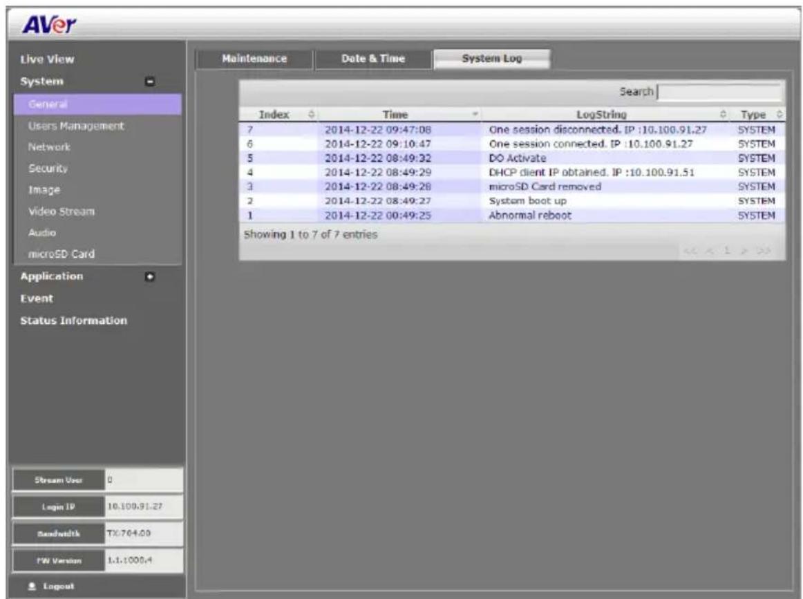
In the System Log, admin can view and search the significant event occurred in the IP camera.
System > User Management
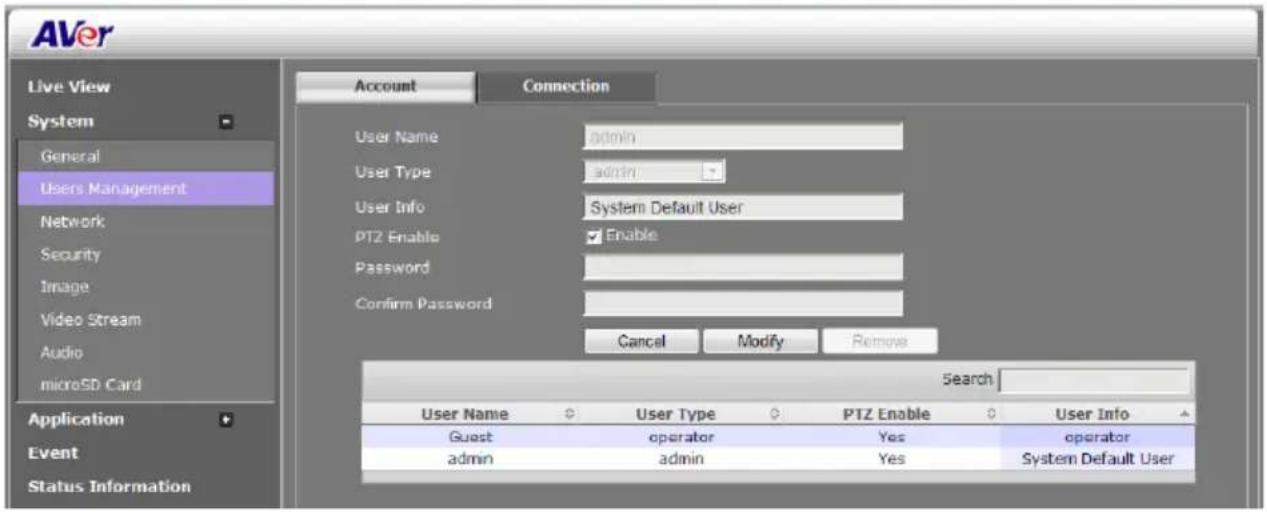
In User Management, only admin level is authorized to create, delete, and edit account to connect to the IP camera and configure the client connection setting. There are 2 tabs in User Management setting: Account and Connection.
System > User Management > Account
In Account page, admin can create, delete and set the access level of the user account.
To Create a User Account
- Click System > User Management > Account tab.
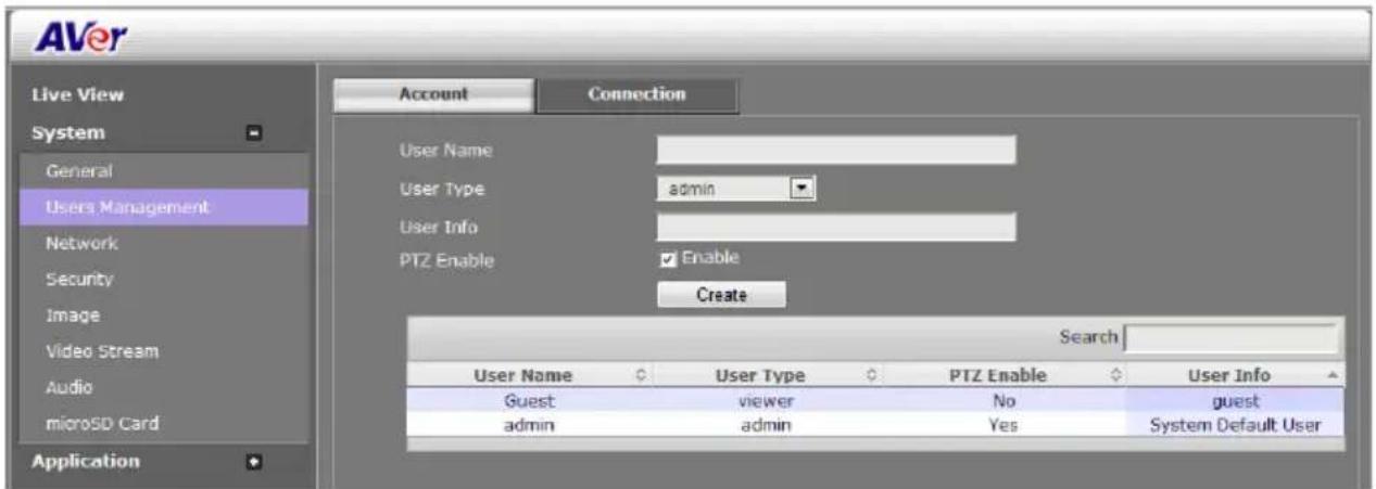
- Enter the User Name, User Info, and select the User Type. Then, click Create.
| User Type | Access rights |
| Admin | Allow to access all the configuration pages. |
| Operator | Allow to preview live image, modify and adjust certain settings; except in System > General, User Management, Network, and SD/microSD Card > Management. As for the I/O Control, admin could enable/disable to allow operator to access it. |
| Viewer | Only allow to access the preview and status information pages. |
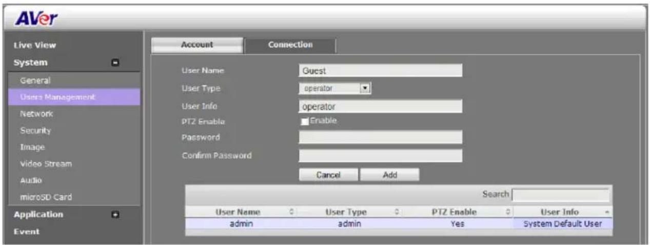
- Enter the same password in Password and Confirm Password column. Then click Add.
To Delete or Edit a User Account
Select the user account that you want to delete or edit.
■ Click Cancel to cancel the operation.
- Click Modify to apply the new changes. Make sure to edit the account before clicking the Modify button.
■ Click Remove to delete the account.
System > User Management > Connection
In Connection page, admin can set the total number of user for accessing the IP camera, and filtering the IP address to allow or deny accessing the IP camera.
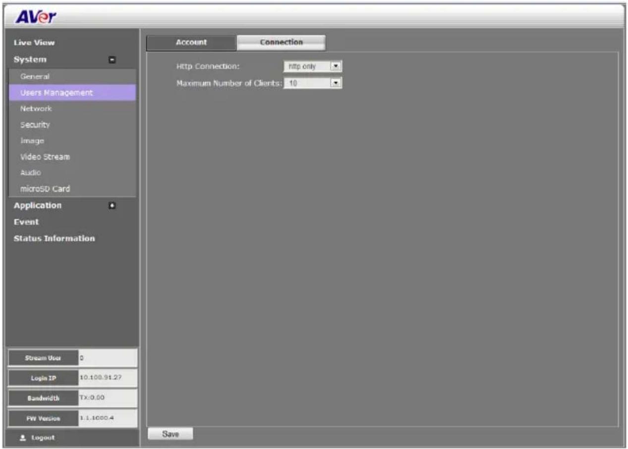
- Http Connection: Select the connection type. For higher security data transmission level, select http & https or http only. The authenticated and encrypted the data is over the SSL (Secure Socket Layer).
■ Maximum Number of Clients: Select the max number of users to simultaneously access the IP camera.
System > Network
In this section, only admin level is authorized to configure the Network settings.
System > Network > Setting
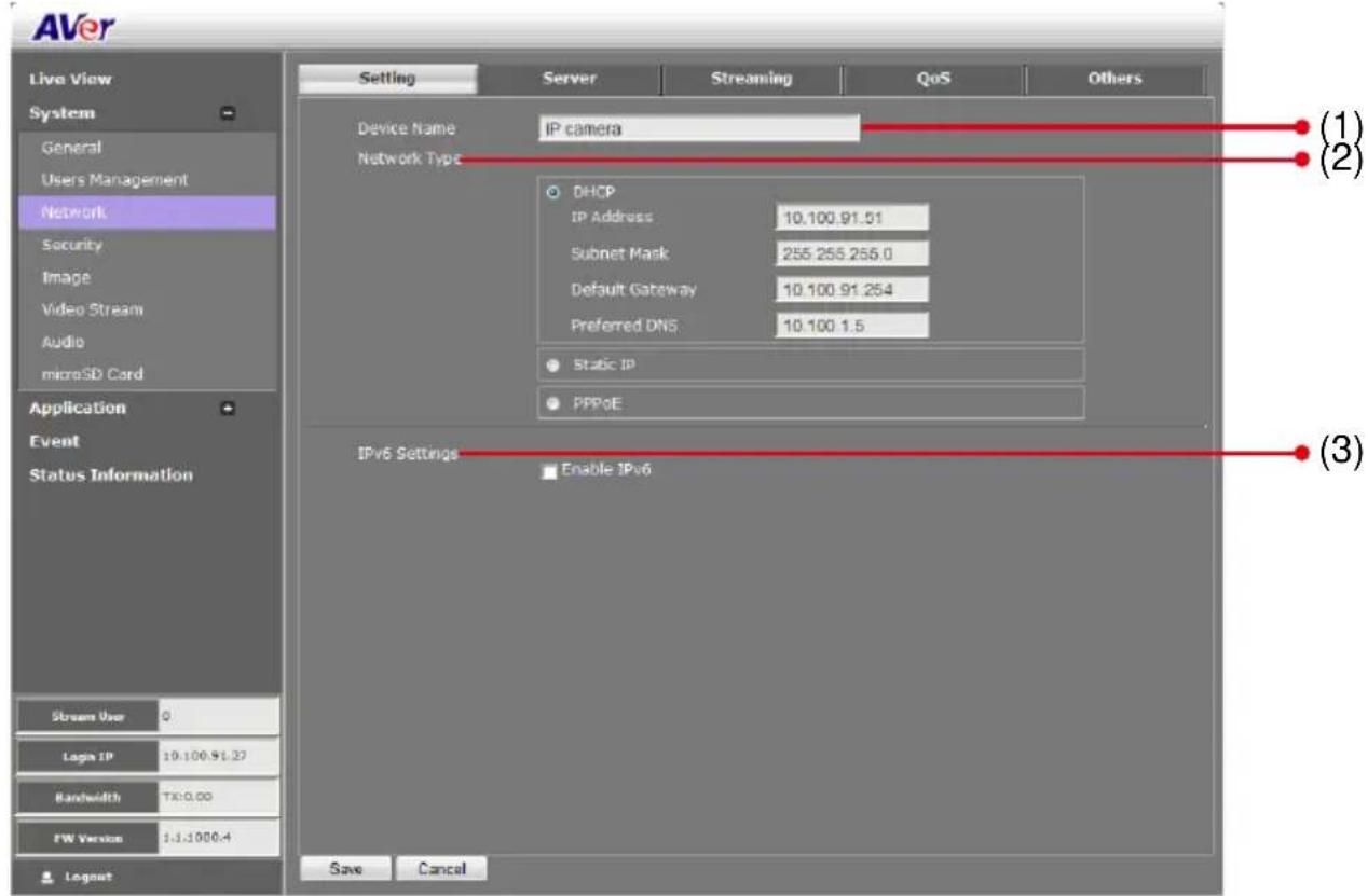
In Setting page, you can configure the type of network connection for IP camera and assign name for the IP camera. Depending on the network connection, IP camera can be accessed from the computer within the same local area network (LAN) or anywhere with Internet connection. After completing the setting, click Save to apply the new setting and Cancel to keep the old setting.
| Name | Function | |
| (1) Device Name | Assign name for the IP camera. | |
| (2) Network Type | Select the type of IP camera network connection.DHCP: select this option to automatically obtain an IP address from the DHCP server, whenever the IP camera is connected to the network.You can use the IP camera UPnP Discovery software in the CD to easily setup the IP camera network. | 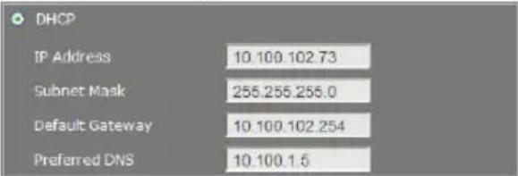 |
| Name | Function |
| (2) Network Type | Static IP: select this option to manually assign a fix IP address to the IP camera. |
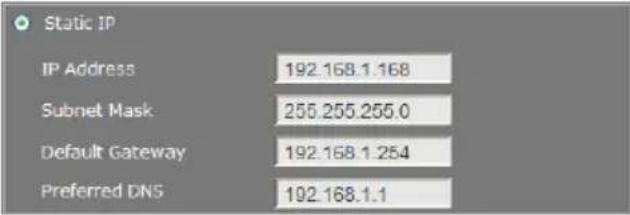 | |
| PPPoE: select this option to access the IP camera anywhere with Internet connection. To use this option, this requires an account provided by the ISP. Set this setting while connected to the LAN and click Save. Connect the IP camera directly to DSL or cable modem. | |
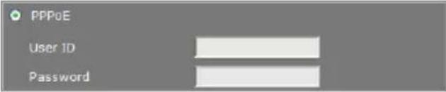 | |
| (3) IPv6 Settings | Enable IPv6 support |
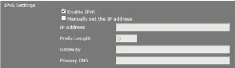 | |
| Select “Manually set the IP address” to specify IP address manually. |
System > Network > Server
In Server page, you can configure the Email, FTP, and NAS setting. It is necessary to configure the server settings so that IP camera can perform the task in the Event setting when a trigger is activated. You can configure either one or all of it. After completing the setting, click Save to apply the new setting and Cancel to keep the old setting.
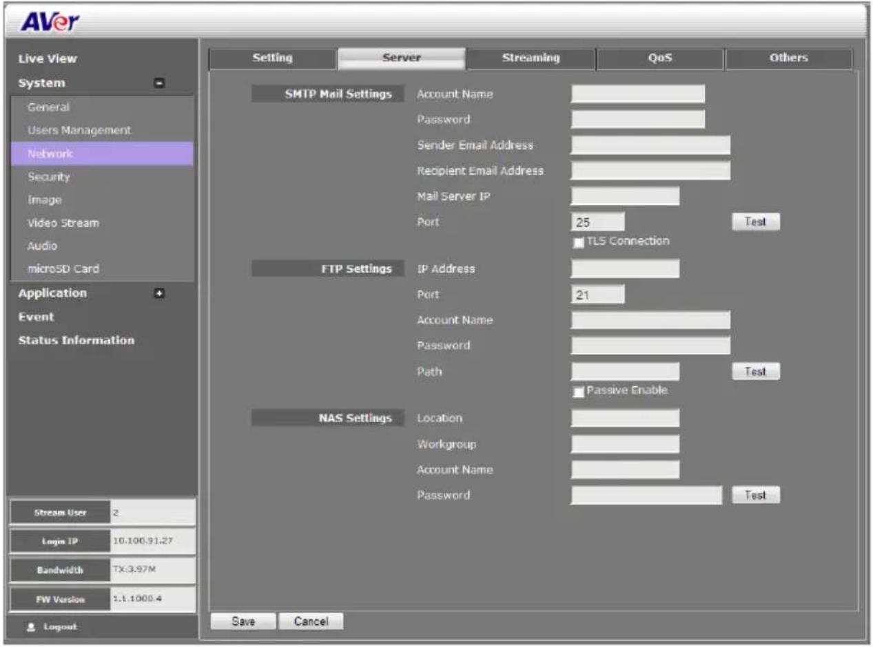
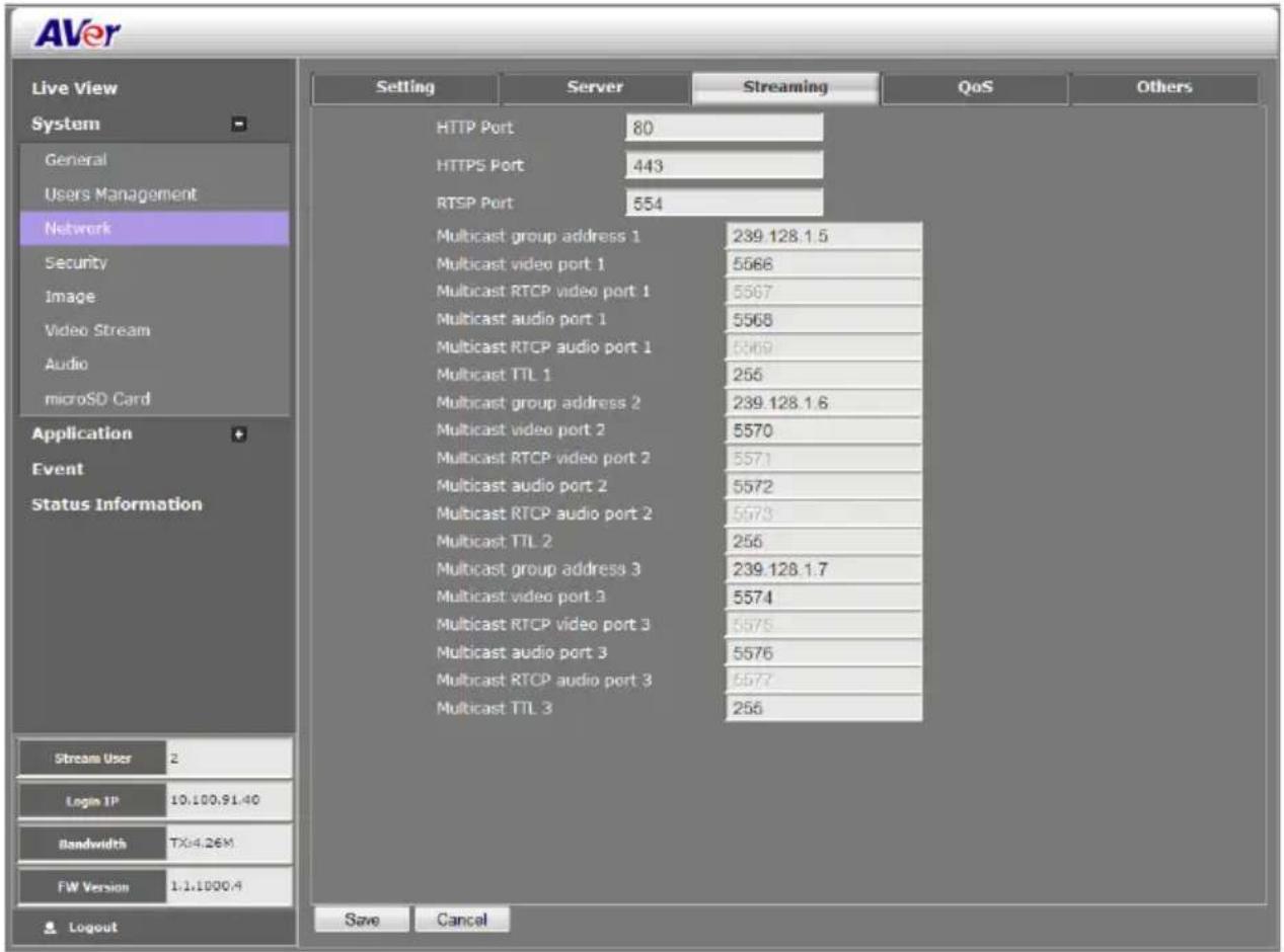
System > Network > Streaming
In Streaming page, you can configure the HTTP, HTTPS, RSTP port, and multicast setting. After completing the setting, click Save to apply the new setting and Cancel to keep the old setting.
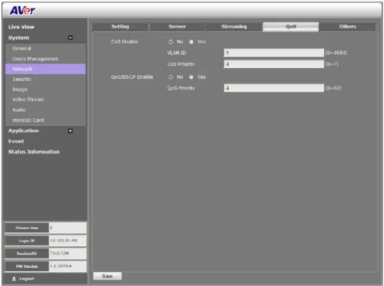
System > Network > QoS
In QoS page, you can configure the Quality of Service setting. Enabling the QoS allows you to set the parameter and prioritize the IP camera to provide stable streaming performance at a certain level in a traffic network.
System > Network > Others
In Others page, you can enable/disable the UPnP setting, setup dynamic domain name service, and setup SNMP settings. DDNS is a service that provides fixed host and domain name for the IP camera with dynamic IP address. It automatically updates the new IP address to the dynamic server of the domain name.
[Note] Click “?” icon can view value validation of port.
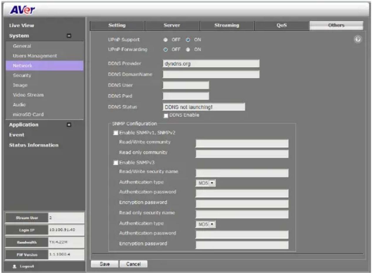
■ UPnP Support: The IP camera supports UPnP, if this service is enabled on your computer.
[Note] 1. UPnP must be enabled on your PC.
2. If your router does not support UPnP function, you can enable the UPnP forwarding and set the port mapping.
■ UPnP Port Forwarding: If the IP camera is installed behind the firewall, please select ON to enable it.
■ DDNS Provider: The DDNS service provider's URL.
■ DDNS DomainName: Enter the domain name that user has applied.
■ DDNS User: Enter the user account that user has registered on DDNS service provider.
■ DDNS Pwd: Enter the password that user has registered on DDNS service provider.
■ DDNS Status: Display the current DDNS status.
■ DDNS enable: Mark it to enable DDNS.
■ SNMP (Simple Network Management Protocol) provides a simple framework for administering networked hardware. SNMPv1, SNMPv2c, and SNMPv3 can be enabled simultaneously.
SNMPv1 and SNMPv2: The term "Community name" in SNMPv1 and SNMPv2 can be roughly regarded as key. The person who has the community name has the authority to read or edit the information of IP camera via SNMP. Check the box to enable SNMPv1 and SNMPv2 protocol, and specify the community name for Read/Write and Read only community. The user who uses read community name to access the IP camera cannot modify any data of this camera
SNMPv3: For data security reason, the authentication and encryption assurances are added when developing SNMPv3. The user has to give not only the security name (the same as "community name" in v1&v2, or sometimes we call it "context name") but the password in order to access the IP camera. Please set Read/Write Security name, Authentication type, Authentication password, Encryption type, Encryption password of Write/Read and Read Only security name respectively. The password must be 8\~64 bits in length.
System > Security
Only admin levels can adjust the Image setting. There are 3 function tabs: IP Filter, 802.1x, RSTP Auth...
System > Security > IP Filter
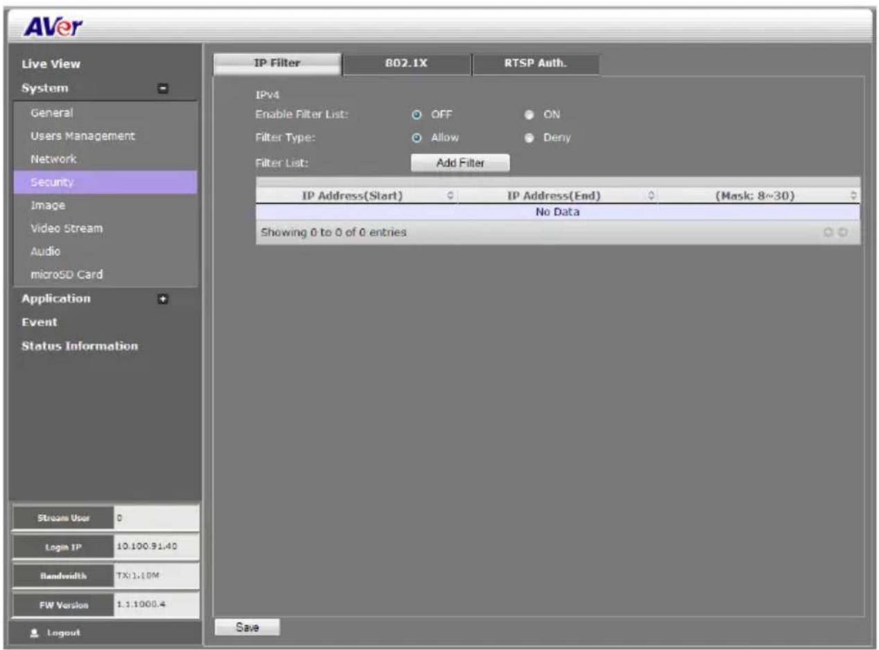
■ Enable Filter List: Select to turn the IP address filtering on or off.
■ Filter Type: Select to allow or deny the IP address in the filter list to access the IP camera.
■ Filter List: Create and display the filtered IP address.
To Add Filter
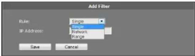
- Click System > Security > IP Filter tab, then, click Add Filter.
- In Rule drop down list, select from the 3 types of rules: Single, Network and Range.
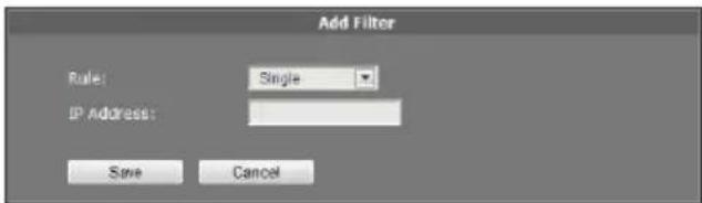
Single – add an IP address
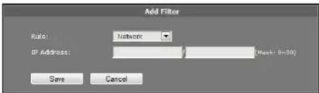
Network – assign a network address and the corresponding subnet mask to be filtered.
Range – assign a range of IP address to be filtered.
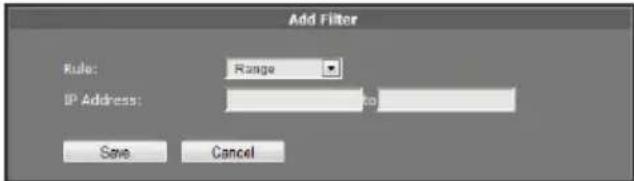
- Click Save to add the created data in the filter list or click Cancel to exit and without saving data.
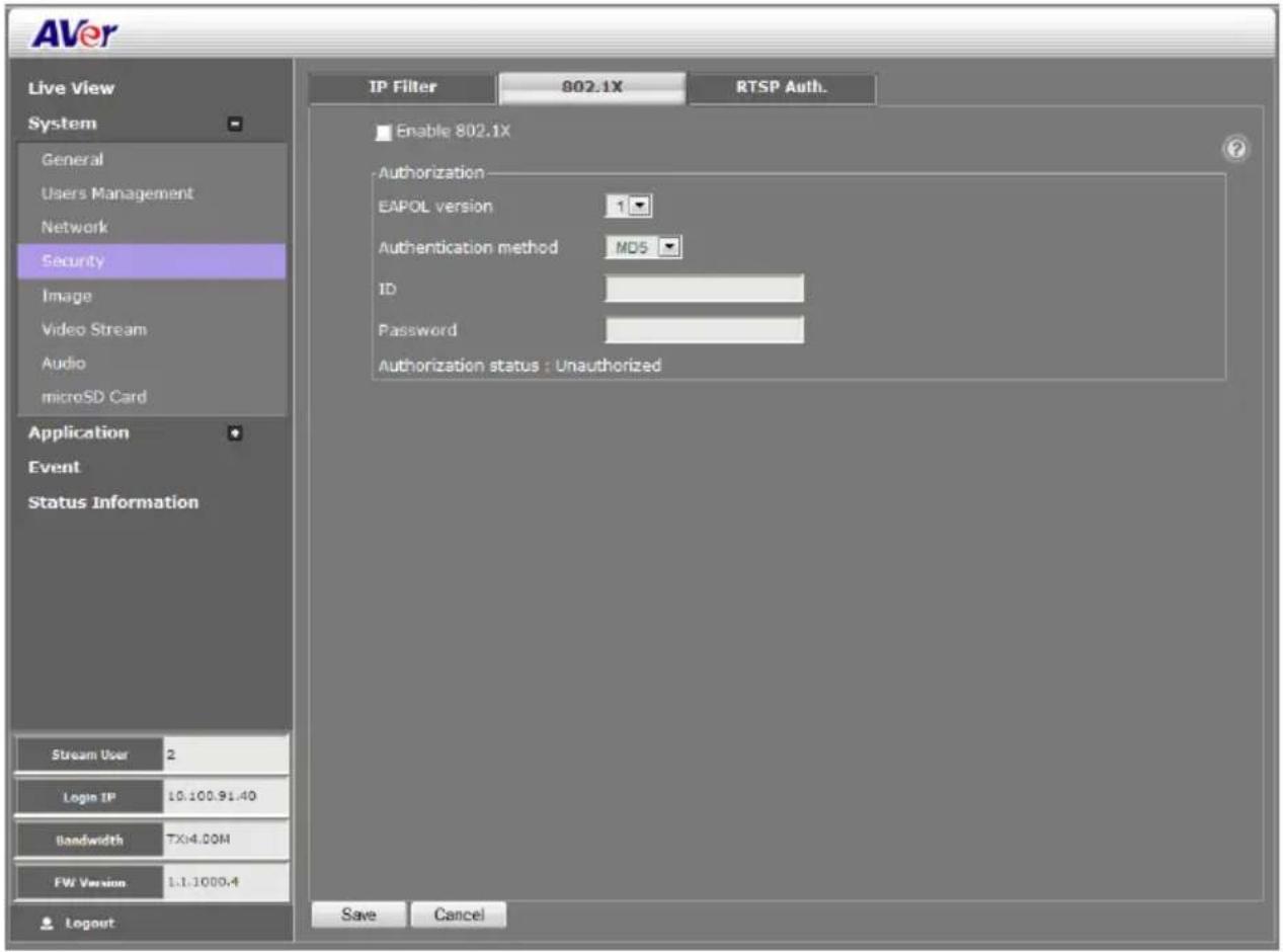
System > Security > 802.1X
IEEE 802.1X is an IEEE Standard for port-based Network Access Control. It provides an authentication mechanism to devices wishing to attach to a LAN or WLAN.
Mark the check box to Enable 802.1X protocol. Select the EAPOL (EAP over LAN) version, Authentication method and enter the ID and Password.
[Note] Click “?” icon can view ID and password's value validation.
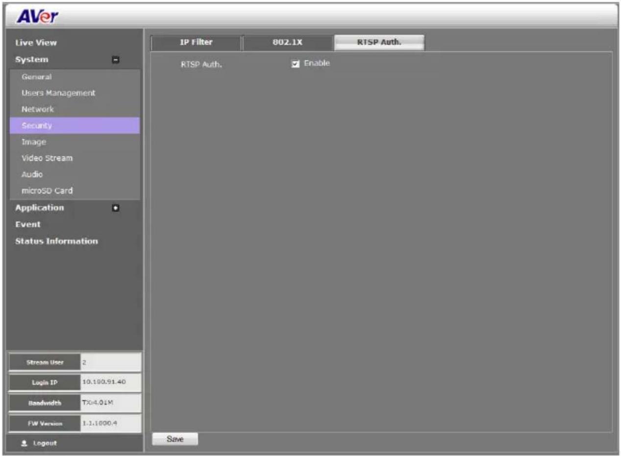
System > Security > RTSP Auth.
Enable/disable RTST authentication.
System > Image
Both admin and operator levels can adjust the Image setting. There are 5 function tabs: OSD, Preference, Exposure, Advanced, and Privacy Mask.
System > Image > OSD
In OSD page, you can enable/disable overlaying time stamp, text title and add logo. After completing the setting, click Save to apply the new setting and Cancel to keep the old setting.
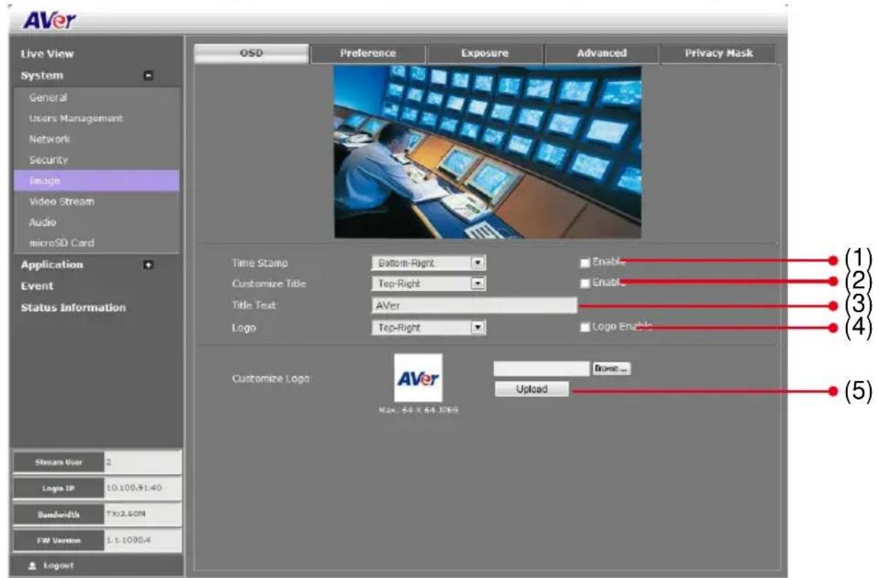
| Name | Function |
| (1) Time Stamp | Select the location of the Time Stamp. Click the checkbox to enable/disable display the date and time stamp. |
| (2) Customize Title | Select the location of the Text Title. Click the checkbox to enable/disable display the text title. |
| (3) Title Text | Enter the title text, e.g. AVer. |
| (4) Logo | Select the location of the logo image file. Click the checkbox to enable/disable display the logo. |
| (5) Customize Logo | Upload your company logo. The maximum size is 64 x 64 pixels. |
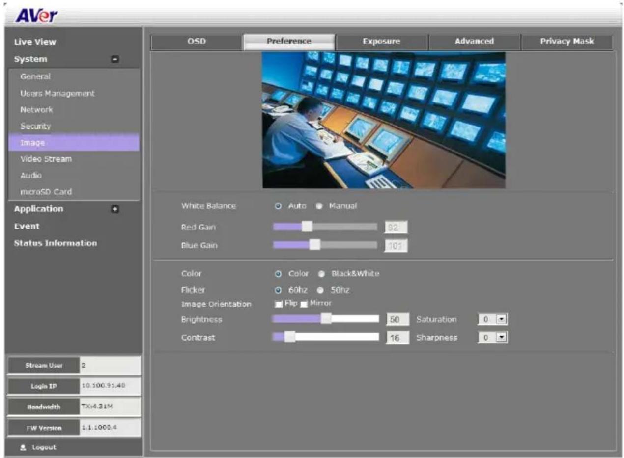
System > Image > Preference
In Preference page, you can tune the IP camera white balance, select display color or black & white, set the flicker frequency, change the video orientation, and adjust the brightness and contrast. After completing the setting, click Save to apply the new setting and Cancel to keep the old setting.
System > Image > Exposure
In Exposure page, you can set the exposure zone, exposure mode, and calibrate the DC Iris. After completing the setting, click Save to apply the new setting and Cancel to keep the old setting.
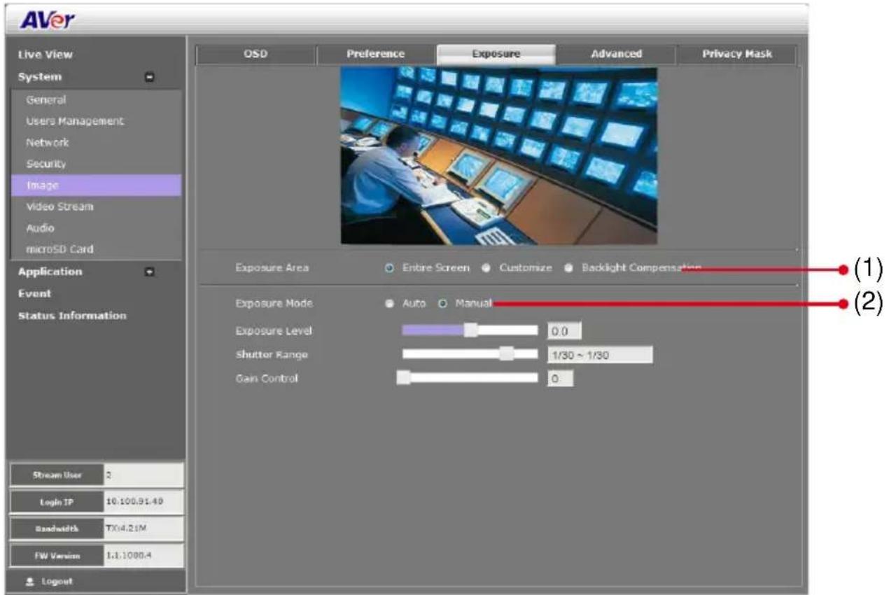
| Name | Function |
| (1) Exposure Area | Select the exposure area to define the light distribution and bring out more details.Entire screen: measure the entire screen to adjust the exposure.Customize: measure the exposure to where the adjustable and movable frame on the screen is located. Move the spot to dark zone to adjust the light condition.Backlight compensation: measure the exposure at the center of the screen. |
Name
Function
(2) Exposure Mode
Select to automatically or manually adjust the exposure.
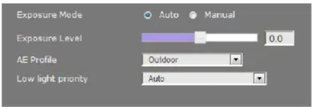
Auto:
Exposure level: Adjust exposure level from -2.0 to +2.0
➢ AE Profile: Select the auto exposure scenes – Indoor, Outdoor, or ManualIRIS.
Low light priority: Select the one you want to prioritize during low light mode image quality or frame rate.
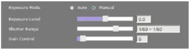
Manual: Adjust the Shutter and Gain Control settings.
System > Image > Advanced
In Advanced page, you can configure the Wide Dynamic Range and Denoise. After completing the setting, click Save to apply the new setting and Cancel to keep the old setting.
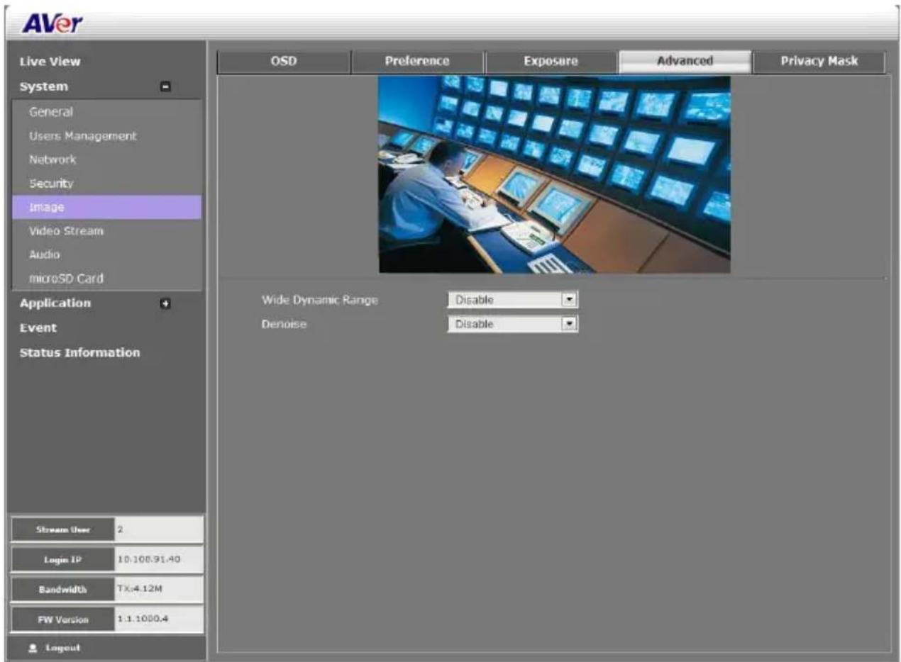
■ Wide Dynamic Range: WDR effectively balances the video image on the screen in both bright and dark areas making it possible to see clear details. There are 3 levels for your choice or disable WDR.
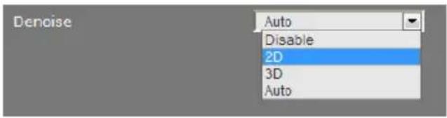
■ Denoise: Select Disable/2D/3D/Auto to reduce the excessive noise on the video image. [Note] The 3D de-noises works under resolution 2M.
System > Image > Privacy Mask
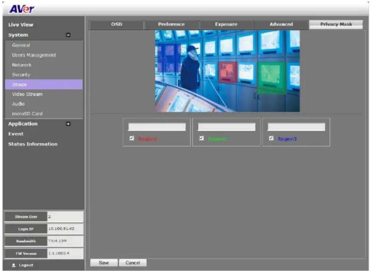
In Privacy Mask page, you can enable 3 privacy masks. Simply adjust the size and position the mask on the area you want to conceal. The viewer will not be able to see the masked area. It will cover the video screen with black frame.
System > Video Stream > Stream Setting
Both admin and operator levels can configure the Video Stream. After configuring the video stream setting, click Save to apply the new setting and Cancel to keep the old setting.
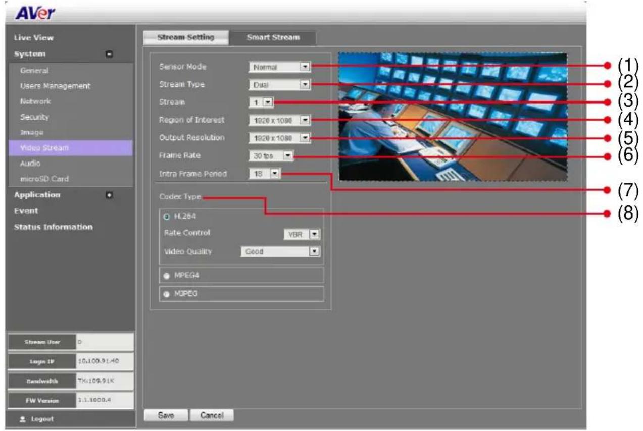
| Name | Function |
| (1) Sensor Mode | Select sensor input resolution from either Norma, Corridor 90, or Corridor 270°. In corridor mode, the screen will flip to allow more deep view.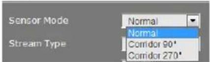 [Note] Available for 3M pixel model or above. [Note] Available for 3M pixel model or above. |
| (2) Stream Type | Select to transmit single or simultaneous multiple streams of 2 or 3 videos.The sensor mode in corridor 90 and 270 only support single and dual stream. |
| (3) Stream | Select the streaming source. |
| (4) Region of Interest | Select the cropping size of video. |
| (5) Output Resolution | Select the video size. |
| (6) Frame Rate | Select frame rate per second of video |
| (7) Intra Frame Period | Select frame internal time period. |
| (8) Code Type | Select the type of video compression codec. The supported codec is H.264, MPEG4, and MJPEG. On each stream, adjust rate control and video quality setting.VBR (Variable Bit Rate): by default use this setting if there is a need to maintain the image quality whenever there is lot of activities on the scene or no motion. This setting keeps the video stream constant as possible which increases the bandwidth requirement when there is high motion and decreases when there is no motion. The bandwidth must be able to accommodate high throughputs.CBR (Constant Bit Rate): use this setting if there is bandwidth concern. This setting is restricted to keep the bit rate setting. This could affect the image quality and frame rate if there is high activity that result in a bit rate that is higher than the set bit rate. |
System > Video Stream > Smart Stream
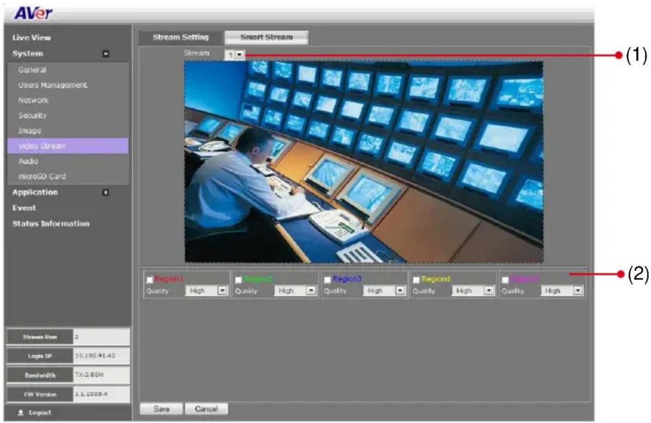
| Name | Function |
| (1) Stream | Select the streaming source. This option is only applied to H.264. |
| (2) Quality | High: video quality of selected area is better than that of un-selected area.Low: video quality of selected area is worse than that of un-selected area |
System > Audio
Both admin and operator levels can configure the IP camera audio setting. After configuring the Audio setting, click Save to apply the new setting and Cancel to keep the old setting.
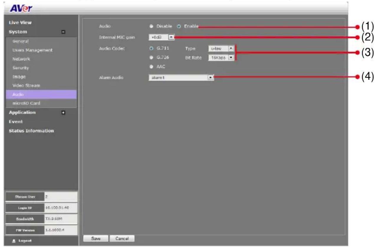
| Name | Function |
| (1) Audio | Select to enable/disable the IP camera built-in mic and mic port. |
| (2) Internal MIC gain | Select to boost up the internal/external mic gain or set to normal. |
| (3) Audio Codec | Select the audio protocol, algorithm, and audio bit rate.G.711: uses Pulse code modulation (PCM) of voice.G.726: uses 40, 32, 24, 16 kbit/s adaptive differential pulse code modulation (ADPCM)AAC: uses AAC codec |
| (4) Alarm Audio | Select to choose from 2 types of alarms sound or customer alarm to use the uploaded alarm sound. The supported sound format are in *.wav (PCM 8KHz/16bit Mono, 10 seconds). |
System > microSD Card > Management
Both admin and operator levels can manage the SD/microSD Card local storage. After managing the SD/microSD Card setting, click Save to apply the new setting and Cancel to keep the old setting. We recommend formatting the SD/microSD card when using it for the first time.
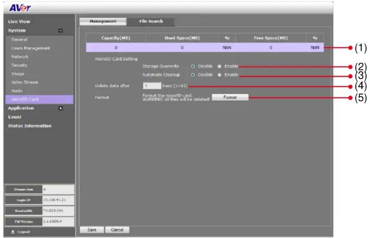
| Name | Function |
| (1) SD/microSD Card Info | Shows the SD/microSD card details. No details will appear if SD/microSD Card is not inserted. |
| (2) Cycle Storage | Enable/disable cycle recording. The old file in the SD/microSD card will be overwritten with the latest one when it has reached the maximum capacity. |
| (3) Automatic Cleanup | Enable/disable automatic clear the data in SD/microSD card. The file will be deleted when it has reached the number of days set in Delete data after [xx] days. |
| (4) Delete data after | Enter the number of days you wish to retain a file. |
| (5) Format | To delete all the data in the SD/microSD card. |
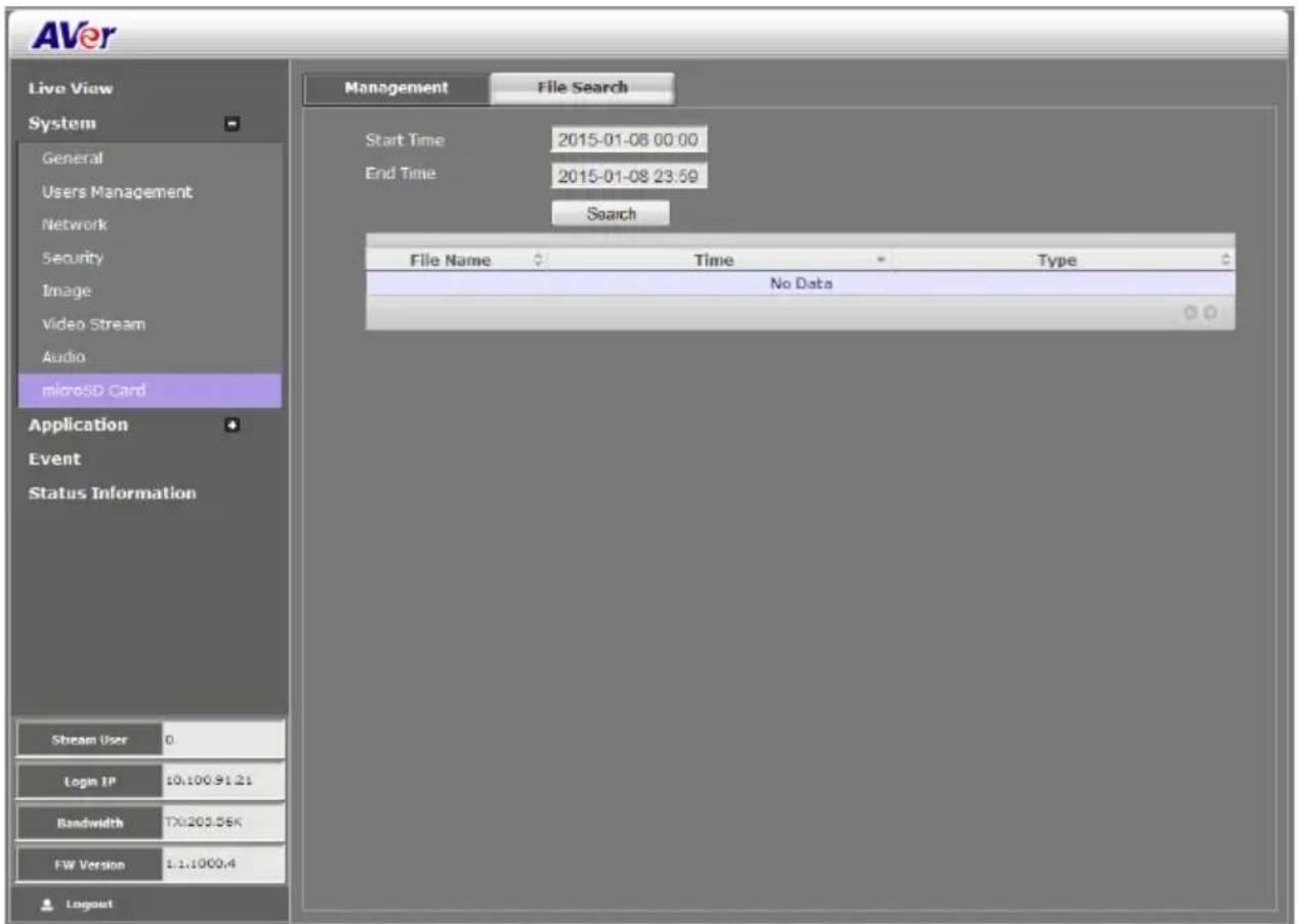
System > microSD Card > File Search
Search the captured image in the SD/microSD card.
Application > Motion Detection
Both admin and operator levels can specify up to 3 areas on the screen to monitor the motion. In the motion detection page, the frame will blink when the motion detected has reached the percentage threshold setting. This feature can be utilized to trigger a response in Event setting.
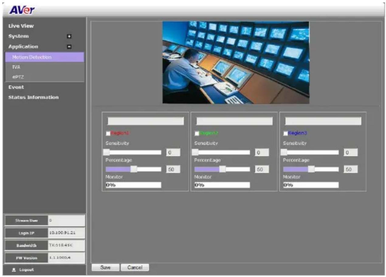
To Set the Motion Detection
- Click Application > Motion Detection.
- Enable the region check box (Region 1, Region 2, Region 3) to create a motion detection frame.
- Move and adjust the frame to the area you want to detect the motion.
- Adjust the sensitivity and percentage. Sensitivity detects the motion on the screen and assesses the changes in pixel thru percentage. The motion detection will activate when the Monitor level reaches the defined percentage.
- Click Save to apply the new setting and Cancel to keep the old setting.
Application > IVA
If IVA function has been disabled, the all corresponded functions are disabled.
To enable IVA function, must meet the following conditions:
- CODEC type is set to "H264" or "MPEG4".
- Stream type is set to "Triple" and Stream 3 resolution set to "640x480".
- Sensor mode set to "Normal" mode.
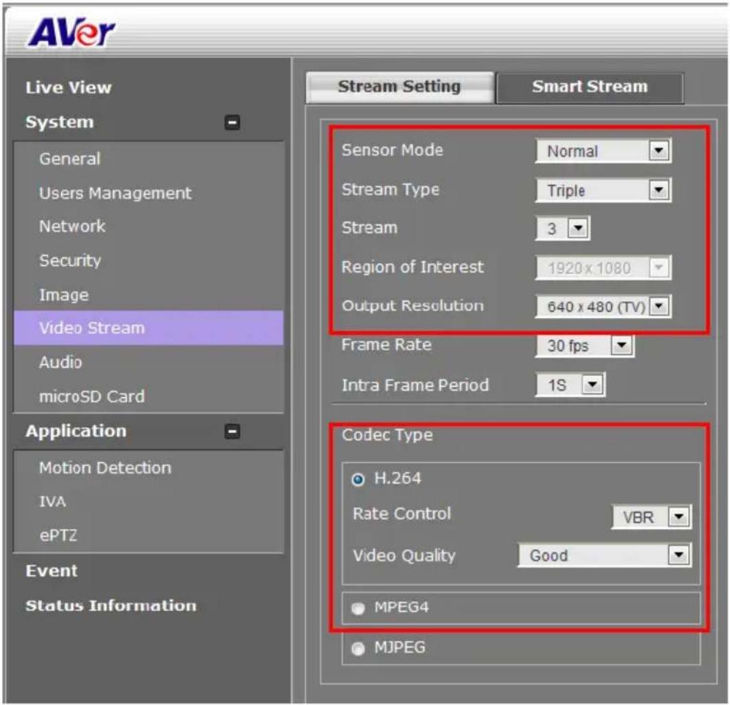
Application > IVA > Cross Detection
Cross detection function detects moving objects that cross the virtual lines that user has set up in IP camera application and to trigger the alarm.
- Click Application > IVA, select Cross Detection from the drop-down list.
- Enable Cross Detection Area 1/2 check box
- You will see the red/green line is shown on the video screen.
- Drag the red line (area 1) or green line (area 2) to set the area for cross detection. You can set both lines for cross detection or one of the lines. There is no priority for the 2 lines; the color is just for you to differentiate when both lines are set.
- After setting the cross detection area, click the arrow to set cross detect direction. The arrow point is the direction of cross way.
- Click Save to save the setting.

- Go to System > Image > Cross Detection Display to set the display status of cross detection line(s). If user wants to see the cross detection line(s) always display on the screen, select
always. If user only wants to see the cross detection line(s) when the cross detection has triggered, select the time in second (1s, 2s, 3s, 4s, or 5s) to display the cross line(s) on the screen.
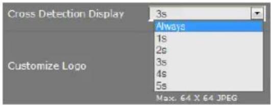
- To set the cross detection alarm, please go to the Event Setting.
Application > IVA > Tampering
Alarm triggers when the following situation has occurred.
-
Spray-painting: Alarm is triggered when the camera has detected the painting sprayed on the camera's view for over 2 seconds.
Intention Block /Cover: Alam is triggered when the camera has detected the camera's view being blocked intentionally over 2 seconds.
■ Accidental redirection: Alarm is triggered when someone re-directs the position or direction of camera accidentally.
■ Defocusing: Alarm is triggered when the camera has lost focus. -
Click Application > IVA, select the Tampering from the drop-down list.
-
Click Save to enable the Tampering function.
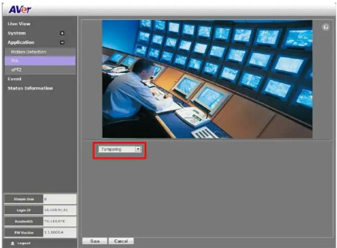
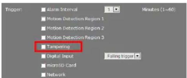
- Go to Event setting and mark Tampering to enable tampering alarm.
- When alarm has been triggered, there will be a red-frame flashing on the live video screen for 30 seconds.
Application > IVA > Missing Object
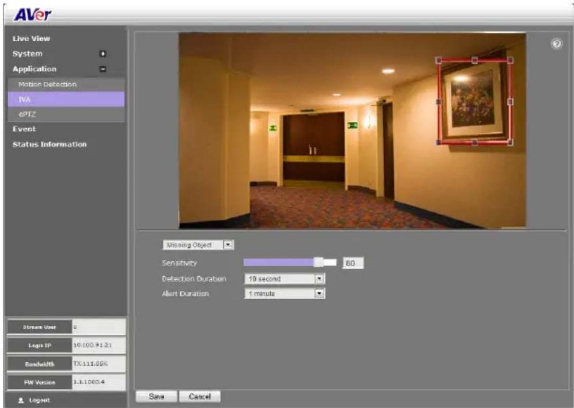
Select a certain object on the screen for the camera system to detect; System gives alarm when the object disappears.
- Click Application > IVA, select the Missing Object from the drop-down list.
- A red frame will show up on the screen. Click and drag the red frame to the object position and click the frame to adjust the size of frame.
- Sensitivity: Set the degree of response of detection.
- Detection Duration: Set the lasting time for camera system to detect the object.
- Alert Duration: Set the alarm lasting time after alarm has been triggered.
- Click Save to save the settings.
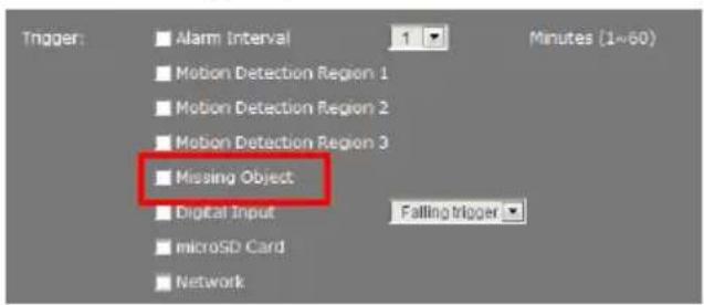
- Go to Event setting and mark Missing Object to enable the alarm.
Application > IVA > Suspicious Object
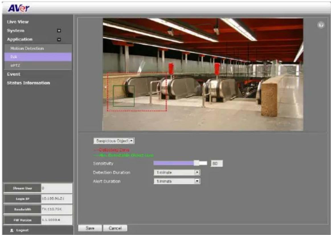
Suspicious Object is an unusual object appears on the screen.
- Click Application > IVA, select the Suspicious Object from the drop-down list.
- A red frame and green frame will show up on the screen. The red frame is defined as detecting zone and green frame is defined as object size frame. Click and drag the red frame to the position and click the frame to adjust the size of frame. Next, click and drag the green frame the detecting zone and adjust the size of object for detection.
- Sensitivity: Set the degree of response of detection.
- Detection Duration: Set the lasting time for camera system to detect the object.
- Alert Duration: Set the alarm lasting time after alarm has been triggered.
- Click Save to save the settings.
- Go to Event setting and mark Suspicious Object to enable the alarm.
Application > ePTZ
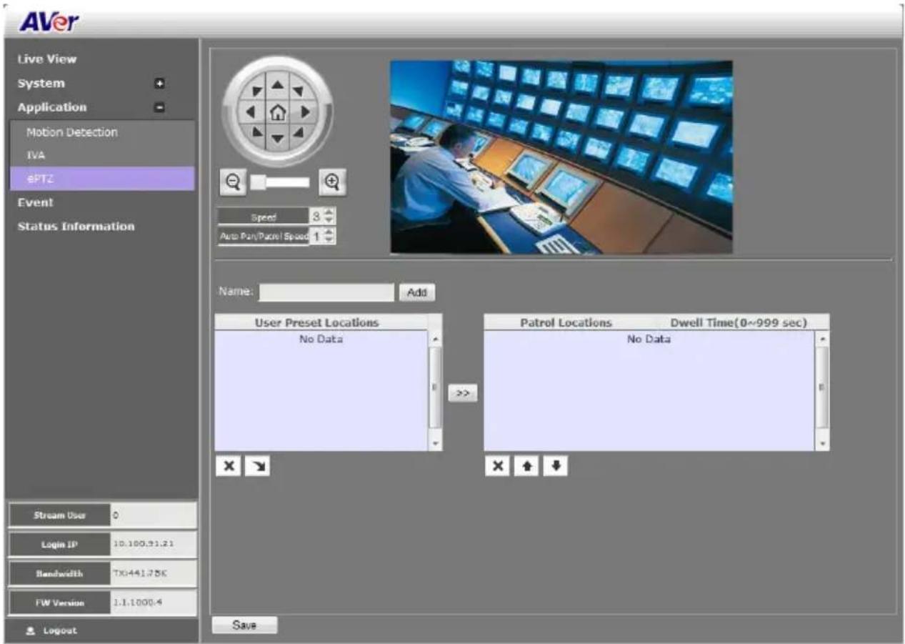
Both admin and operator levels can customize the ePTZ setting. In this section, you can set the patrol target area, patrol sequence and dwelling time.
To Setup the ePTZ
- Click Application > ePTZ.
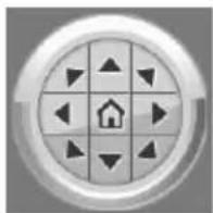
- Use the direction buttons and zoom button to locate the patrol target area. Press 📄 to view the full image and reset the zoom level.

- Type a name for the patrol shooting area e.g. type "UpperLeft" in the Name text box and press Add button. The preset target area will be listed in the User Preset Locations. Click × to delete the preset target area and □ show the preset target area. Repeat step 2 and 3 to add more preset locations.

- Select the preset target area in the list and press ▶to create the patrol sequence. The selected present target area will be listed in the Patrol Locations.
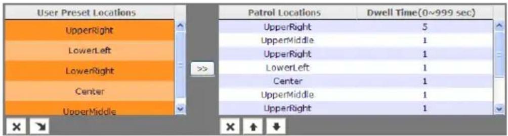
- Set the dwelling time for how long you want to stay in the preset target area. Double-click and enter the time. Then click OK or press enter to apply the changes.
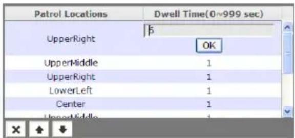
- Click ☐ to delete the selected preset location in the Portal Locations list and to arrange the patrol order.
- Click Save to implement the preset patrol setting.
Event Setting
Both admin and operator levels can configure the Event setting. In this section, the IP camera can be configured to perform an action when an event is triggered at the specified time.
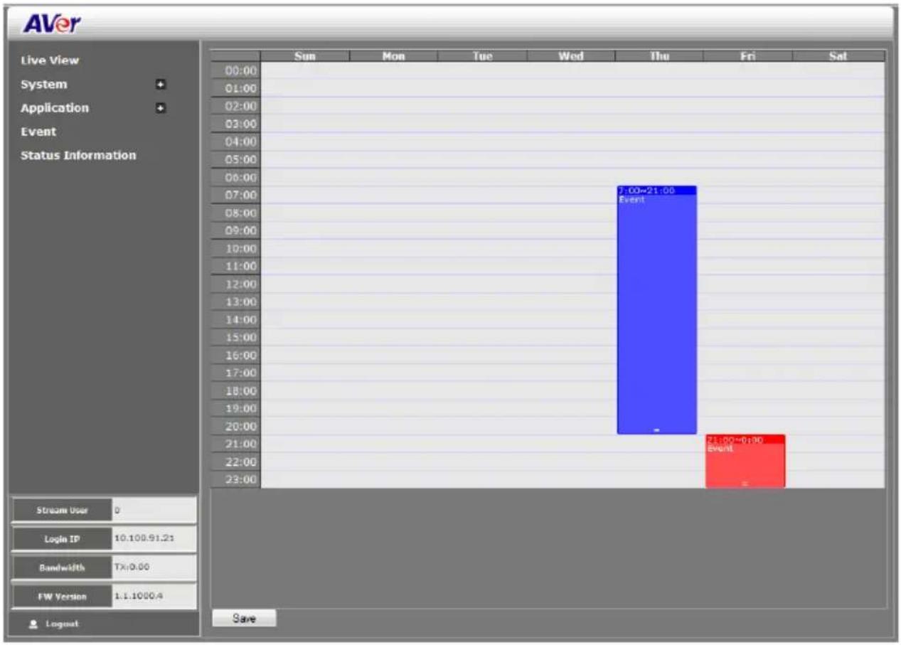
bar
| Time | Event | | :--- | :--- | | 07:00 | 7:00-21:00 Event | | 21:00 | 21:00-01:00 Event |To Setup the Event
- Click Event.
- On the time table, click-drag to select the time period to specify the period of the event.
- Type a name for the event. The naming rule is no space between each character and number and no special character. The length of name is 20 in both characters and numbers.
- Select the color to represent the event
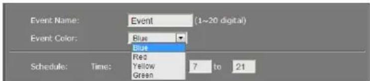
- Set the schedule. You can set the time period and choose another day(s) to apply the same event setting.

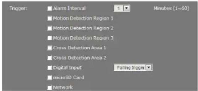
- Enable the type of event for the IP camera to trigger.
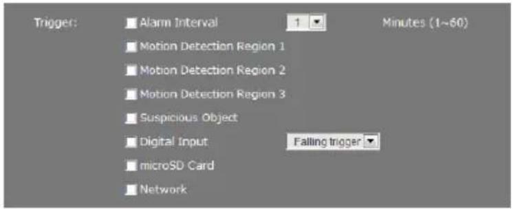
- Alarm Interval
This triggers the IP camera based on the time that use has set in Minutes column. The interval time rage is 1\~60 minutes.
- Motion Detection Region 1/2/3
This triggers the IP camera when a motion is detected on the motion detection region.
- Alarm Cross Detection Area 1/2
This triggers the IP camera when a cross detection is detected on the cross detection area.
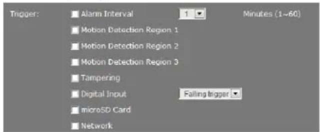
- Tampering
This triggers the IP camera when tampering situation has met (Spray-painting, Intention Block /Cover, Accidental redirection, or Defocusing). The tampering alarm selection will display only when tampering function has enabled.
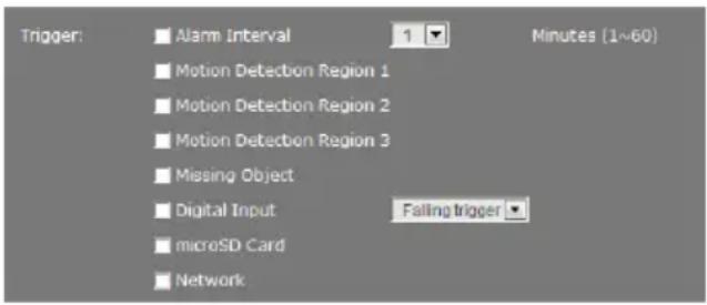
- Missing Object
This triggers the IP camera when a missing object is occurred. The missing object alarm selection will display only when missing object function has enabled.
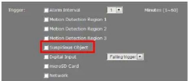
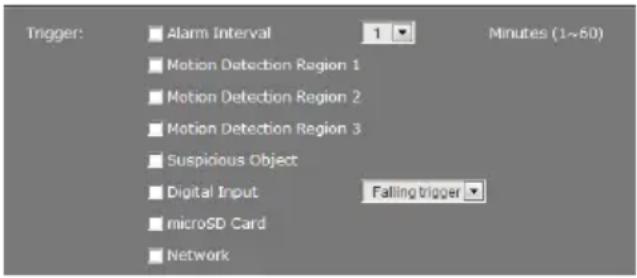
- Suspicious Object
This triggers the IP camera when a suspicious object is occurred. The suspicious object alarm selection will display only when suspicious object function has enabled.
- Digital Input
This triggers the IP camera when the external digital input device or sensor is activated. Select the trigger type –Falling trigger or Rising trigger.
- microSD Card
This triggers the IP camera when the microSD card is removed.
- Network
This triggers the IP camera when the Internet connection is disconnected.
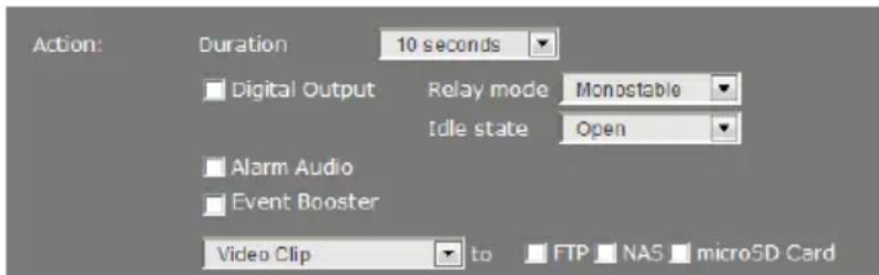
- Select the type of action for the IP camera to perform when a trigger is activated. Set the duration. Choose digital output to send recorded video or still image, Alarm Audio to sound the alarm, or enable/disable Event Booster. Then select the type of server/media to where to send the file. To configure the FTP and NAS setting, go to System > Network > Server.
[Note]
a. Snapshot and System log support sending the file thru Mail, and storing in FTP, NAS or microSD card. You can enable multiple options to send and save the captured image.
b. Video Clip supports storing in FTP, NAS or microSD card. You can only select one storage option to save the video file. For better performance, we recommend to set the
video stream is default value.
- Click OK to add the event setting, Delete to remove, and Cancel to without save and close the event setting.
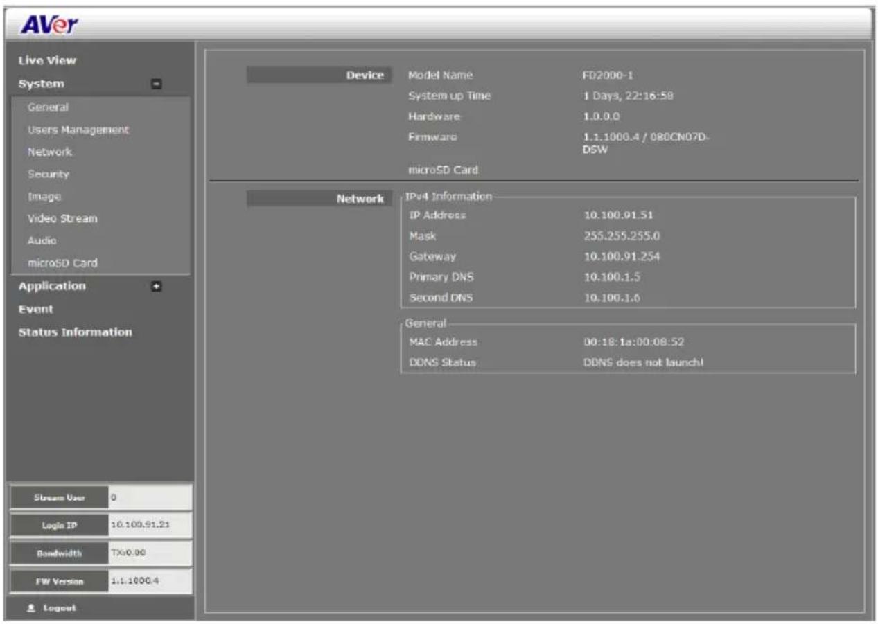
Status Information
Show the information about the device and network setting.
Limited Warranty
AVer Information, Inc. (“AVer”) warrants that the applicable product (“Product”) substantially conforms to AVer’s documentation for the product and that its manufacture and components are free of defects in material and workmanship under normal use. “You” as used in this agreement means you individually or the business entity on whose behalf you use or install the product, as applicable. This limited warranty extends only to You as the original purchaser. Except for the foregoing, the Product is provided “AS IS.” In no event does AVer warrant that You will be able to operate the Product without problems or interruptions, or that the Product is suitable for your purposes. Your exclusive remedy and the entire liability of AVer under this paragraph shall be, at AVer’s option, the repair or replacement of the Product with the same or a comparable product. This warranty does not apply to (a) any Product on which the serial number has been defaced, modified, or removed, or (b) cartons, cases, batteries, cabinets, tapes, or accessories used with this product. This warranty does not apply to any Product that has suffered damage, deterioration or malfunction due to (a) accident, abuse, misuse, neglect, fire, water, lightning, or other acts of nature, commercial or industrial use, unauthorized product modification or failure to follow instructions included with the Product, (b) misapplication of service by someone other than the manufacturer’s representative, (c) any shipment damages (such claims must be made with the carrier), or (d) any other causes that do not relate to a Product defect. The Warranty Period of any repaired or replaced Product shall be the longer of (a) the original Warranty Period or (b) thirty (30) days from the date of delivery of the repaired or replaced product.
Limitations of Warranty
AVer makes no warranties to any third party. You are responsible for all claims, damages, settlements, expenses, and attorneys' fees with respect to claims made against You as a result of Your use or misuse of the Product. This warranty applies only if the Product is installed, operated, maintained, and used in accordance with AVer specifications. Specifically, the warranties do not extend to any failure caused by (i) accident, unusual physical, electrical, or electromagnetic stress, neglect or misuse, (ii) fluctuations in electrical power beyond AVer specifications, (iii) use of the Product with any accessories or options not furnished by AVer or its authorized agents, or (iv) installation, alteration, or repair of the Product by anyone other than AVer or its authorized agents.
Disclaimer of Warranty
EXCEPT AS EXPRESSLY PROVIDED OTHERWISE HEREIN AND TO THE MAXIMUM EXTENT PERMITTED BY APPLICABLE LAW, AVER DISCLAIMS ALL OTHER WARRANTIES WITH RESPECT TO THE PRODUCT, WHETHER EXPRESS, IMPLIED, STATUTORY OR OTHERWISE, INCLUDING WITHOUT LIMITATION, SATISFACTORY QUALITY, COURSE OF DEALING, TRADE USAGE OR PRACTICE OR THE IMPLIED WARRANTIES OF MERCHANTABILITY, FITNESS FOR A PARTICULAR PURPOSE OR NONINFRINGEMENT OF THIRD PARTY RIGHTS.
Limitation of Liability
IN NO EVENT SHALL AVER BE LIABLE FOR INDIRECT, INCIDENTAL, SPECIAL, EXEMPLARY, PUNITIVE, OR CONSEQUENTIAL DAMAGES OF ANY NATURE INCLUDING, BUT NOT LIMITED TO, LOSS OF PROFITS, DATA, REVENUE, PRODUCTION, OR USE, BUSINESS INTERRUPTION, OR PROCUREMENT OF SUBSTITUTE GOODS OR SERVICES ARISING OUT OF OR IN CONNECTION WITH THIS LIMITED WARRANTY, OR THE USE OR PERFORMANCE OF ANY PRODUCT, WHETHER BASED ON CONTRACT OR TORT, INCLUDING NEGLIGENCE, OR ANY OTHER LEGAL THEORY, EVEN IF AVER HAS ADVISED OF THE POSSIBILITY OF SUCH DAMAGES. AVER'S TOTAL, AGGREGATE LIABILITY FOR DAMAGES OF ANY NATURE, REGARDLESS OF FORM OF ACTION, SHALL IN NO EVENT EXCEED THE AMOUNT PAID BY YOU TO AVER FOR THE SPECIFIC PRODUCT UPON WHICH LIABILITY IS BASED.
Governing Law and Your Rights
This warranty gives you specific legal rights; You may also have other rights granted under state law. These rights vary from state to state.
- Federal Communications Commission Statement
- Class A ITE
- European Community Compliance Statement (Class A)
- COPYRIGHT
- Trademark
- NOTICE
- WARNING
- Table of Contents
- IMPORTANT SAFEGUARD....1
- PACKAGE CONTENTS....2
- IP CAMERA INSTALLATION....3
- INSERT MICROSD CARD 4
- EXTERNAL AUDIO CABLE INSTALLATION....5
- Important Safeguard
- Package Contents
- IP Camera Installation
- Insert microSD Card
- External Audio Cable Installation
- Using the IP Camera Browser Interface
- Live View
- System > General
- System > General > Maintenance
- Name
- Function
- Firmware Upgrade
- To Upgrade the IP Camera Firmware
- System > General > Date & Time
- System > General > System Log
- System > User Management
- System > User Management > Account
- To Create a User Account
- To Delete or Edit a User Account
- System > User Management > Connection
- System > Network
- System > Network > Setting
- System > Network > Server
- System > Network > Streaming
- System > Network > QoS
- System > Network > Others
- System > Security
- System > Security > IP Filter
- To Add Filter
- System > Security > 802.1X
- System > Security > RTSP Auth.
- System > Image
- System > Image > OSD
- System > Image > Preference
- System > Image > Exposure
- Exposure Mode
- Auto:
- System > Image > Advanced
- System > Image > Privacy Mask
- System > Video Stream > Stream Setting
- System > Video Stream > Smart Stream
- System > Audio
- System > microSD Card > Management
- System > microSD Card > File Search
- Application > Motion Detection
- To Set the Motion Detection
- Application > IVA
- Application > IVA > Cross Detection
- Application > IVA > Tampering
- Application > IVA > Missing Object
- Application > IVA > Suspicious Object
- Application > ePTZ
- To Setup the ePTZ
- Event Setting
- To Setup the Event
- - Alarm Interval
- - Motion Detection Region 1/2/3
- - Alarm Cross Detection Area 1/2
- - Tampering
- - Missing Object
- - Suspicious Object
- - Digital Input
- - microSD Card
- - Network
- [Note]
- Status Information
- Limited Warranty
- Limitations of Warranty
- Disclaimer of Warranty
- Limitation of Liability
- Governing Law and Your Rights
Brand : AVer
Model : FD2000
Category : Security Camera