
AUV105UR4RAB4 - Air conditioner HISENSE - Free user manual and instructions
Find the device manual for free AUV105UR4RAB4 HISENSE in PDF.


| Product Type | Ceiling & Floor Air Conditioner (Heat Pump) |
| Available Capacities | 18K, 24K, 36K, 42K, 48K, 60K Btu/h |
| Installation Options | Ceiling-mounted or floor-standing |
| Refrigerant | R410A (environment-friendly, ozone layer safe) |
| Power Supply (example 42K/48K/60K) | 380-415V 3N~, 50Hz, ELB 32A |
| Power Supply (example 18K/24K) | 220-240V ~, 50Hz, ELB 20A/32A |
| Maximum Tube Length | 30m (18K) / 50m (24K-60K) |
| Maximum Height Difference | 15m |
| Additional Refrigerant per Meter (exceed 5m) | 15g/m (18K) / 35g/m (24K-60K) |
| Outdoor Working Temperature Range (Cooling) | -15°C to 48°C |
| Outdoor Working Temperature Range (Heating) | -15°C to 24°C |
| Storage Temperature | -25°C to 60°C |
| Storage Humidity | 30% to 80% |
| Indoor Unit Thickness | 230mm (for ceiling installation) |
| Timer | 24-hour ON/OFF timer |
| Special Features | Mute operation, self recovery after power break, fault self-diagnose, anti-freezing, cold air prevention, defrosting |
| Filter Cleaning Indicator | Yellow LED lights when filter needs cleaning |
| Drain Pipe Diameter | De25 (25mm) |
| Refrigerant Pipe Connections | 3 directions: rear, right, top |
| Safety Features | Compressor 3-minute delay restart, overload protection, earthing required |
| Warranty | Refer to dealer or manufacturer |
Frequently Asked Questions - AUV105UR4RAB4 HISENSE
User questions about AUV105UR4RAB4 HISENSE
0 question about this device. Answer the ones you know or ask your own.
Ask a new question about this device
Download the instructions for your Air conditioner in PDF format for free! Find your manual AUV105UR4RAB4 - HISENSE and take your electronic device back in hand. On this page are published all the documents necessary for the use of your device. AUV105UR4RAB4 by HISENSE.
USER MANUAL AUV105UR4RAB4 HISENSE
USE AND INSTALLATION INSTRUCTIONS
Thank you very much for purchasing this Air Conditioner. Please read this useful instructions and using this appliance and keep this manual for future reference.
Welcome to use our product!
Thanks for trusting us.
Please read this manual carefully before installation!
Keep it properly for future use after installation!
Features of Ceiling&Floor Air Conditioner
- Save Installation Space The indoor unit's thickness is only 230mm, can be installed inside the ceiling conveniently.
- Flexible Installation Options According to the actual installation space, the indoor unit can be installed in the ceiling or on the floor. One unit, two installation method.
- High Efficiency and Environment Friendly New Refrigerant-R410A R410A can protect the environment and do not harm to the ozone layer.
- 24-hour Timer ON and OFF This Timer can be set to automatically turn the unit on or off within a 24-hour period.
- Mute Operation The excellent fan design enable the airflow to be quiet and smooth with minimum noise.
- Various Refrigerant Pipe Connect Methods The refrigerant pipe can be connected from 3 different directions(rear, right or top). More methods, more conveniently.
- Self Recovery of Power Break When the power supply is recovered after break, all preset are still effective and the air-conditioner can run according to the original setting.
- Fault Self-diagnose Function When there is something wrong with the air-conditioner, the micro computer could diagnose the faults, which can be read from the display and is convenient for maintenance.
Contents
Alert Symbols 1
Caution Statements 2
Composition of the Air-Conditioner 3
Operation Manual
Special Remarks 5
Trouble shooting 5
Diagram of Refrigerant Cycle & Wiring
- Refrigerant Flow Diagram 7
2.Electrical Wiring Diagram 7
Installation and Maintenance
-
Safety Notice 8
-
The Tools and Instruments for Installation 9
-
The Installation of the Indoor Unit 9
3.1 Before Installation---- 9
3.2 Installation Location 11
3.3 Installation 11
- Refrigerant Pipe 14
4.1 The Pipe Material 14
4.2 The Connection of the Pipe 14
-
Drain Piping 15
-
Electrical wiring 16
-
Attaching the Air Return Grille 16
-
The Installation of the Outdoor Unit 17
8.1 Installation Sites 17
8.2 Installation of the Outdoor Unit 17
- Refrigerant Tubing 18
9.1 Flaring with Tube Expander 18
9.2 Connecting Tubing Between Indoor and Outdoor Units 18
9.3 Heat Insulation of the Refrigerant Tube 18
9.4 Taping the Tubes 18
9.5 Finishing the Installation 18
- Air Purging and Test Run 18
10.1 Air Purging with a Vacuum Pump----18
10.2 Leak Test 19
10.3 Tidy Up the Tubing 19
10.4 Test Run 19
10.5 Common 20
NOTE
● This heat pump air conditioner has been designed for the following temperatures. Operate the heat pump air-conditioner within this range.
| Outdoor Working Temperature(°C) | ||
| Maximum | Minimum | |
| Cooling Operation | 48 | -15 |
| Heating Operation | 24 | -15 |
●Storage condition: Temperature -25\~60°C Humidity 30%\~80%
Alert Symbols:
DANGER : The symbol refers to a hazard which can result in severe personal injury or death.
WARNING : The symbol refers to a hazard or an unsafe practice which may result in severe personal injury or death.
CAUTION : The symbol refers to a hazard or an unsafe practice which may result in personal injury, product or property damage.
It refers to the remarks and instruction to the operation, maintenance, and service.
Caution Statements
- We recommend that this air-conditioner be installed properly by qualified installation technicians in accordance with the installation instructions provided with the unit.
- Before installation, check if the voltage of the power supply in your home or office is the same as the voltage shown on the nameplate.

DANGER
- You must not carry on any transformation to this product, otherwise, it may possibly cause such consequences as the water leakage, the breakdown, the short-circuit, an electric shock, fire, etc.
- The work such as tube line welding, etc. should be carried out far away from the flammable explosive material vessels, including the air-conditioner refrigerant, to guarantee the security of the site.
- To protect the air-conditioner from heavy corrosion, avoid installing the outdoor unit where salty seawater can splash directly onto it or in sulphurous air near a spa. Do not install the air-conditioner where excessively high heat-generating objects are placed.

WARNING
- If the supply cord is damaged, it must be replaced by the factory or its service department in case of danger.
- The place where this product is installed must have the reliable electrical earth facility and the equipment. Please do not connect the grounding of this product to various kinds of air-feeding tube lines, the drain lines, the lightning protection facility as well as other tube lines to avoid receiving an electric shock and damages caused by other factors.
- Wiring must be done by a qualified electrician. All the wiring must comply with the local electrical codes.
- Consider the capacity of the electric current of your electrical kilowatt-hour meter wires and socket before installation.
-
The power wire where this product is installed is supposed to have the independent leakage protective device and the electric current over-load protection device which are provided for this product.
● The appliance is not to be used by persons (including children) with reduced physical, sensory or mental capabilities, or lack of experience and knowledge, unless they have been given supervision or instruction. Children should be supervised not to play with the appliance.
● Means for disconnection, which can provide full disconnection in all poles, must be incorporated in the fixed wiring in accordance with the wiring rules. -
Read this manual carefully before using this air-conditioner. If you still have any difficulties or problems, consult your dealer for help.
- The air-conditioner is designed to provide you with comfortable room conditions. Use this unit only for its intended purpose as described in this instruction manual.

WARNING
- Never use gasoline or other inflammable gas near the air-conditioner, which is very dangerous.

CAUTION
- Do not turn the air-conditioner on and off from the power main switch. Use the ON/OFF operation button.
- Do not stick anything into the air inlet and air outlet of both the indoor and outdoor units. This is dangerous because the fan is rotating at a high speed.
- Do not cool or heat the room too much if babies or invalids are present.
Indoor Unit

Outdoor Unit

natural_image
Technical line drawing of a front-mounted air conditioning unit with a circular fan blade (no text or symbols)18K,24K,36K,42K

natural_image
Technical line drawing of a dual-panel HVAC fan unit with ventilation patterns (no text or symbols)48K,60K
Notes:
Figures in the manual are only simple representation of the appliance, its may not comply with the appearance of the air conditioner you purchased.
Vertical adjustment louver swing automatically function is only available for some models.
Composition of the Air-conditioner
Remote controller(optional)
You can control the air-conditioner with the wire remote controller or wireless remote controller.
It is used for controlling power ON/OFF, setting the running mode, temperature, fan speed and other functions.
There are different types of remote controllers can be selected.
Operate instruction will be further specified in remote controller's manual separately.
Please read it carefully before using this appliance and keep it for future reference.
Wire remote controller

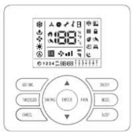
Wireless remote controller

flowchart
graph TD
    A["Run indicator (Red)"] --> B["Signal receiving section"]
    B --> C["Defrost indicator ( )Green\nIt lights on during the defrost.\nIt lights off when defrost finishes."]
    B --> D["Returns signal from the remote controller."]
    A --> E["*Filter clean( )Yellow\nIt lights on when the filter should be cleaned."]
    A --> F["Timer indicator ( )Green\nIt lights on when timer is in use.\nIt lights off when timer finishes."]
    A --> G["Emergency switch\nThe filter clean is reset if press the switch.\nPress it the appliance will be stopped when the unit is running:\nPress it for 5s,the appliance will be forced cooling when the unit is OFF."]
    A --> H["Run indicator (Red)"]
- The figures in this manual are based on the external view of a standard model. Consequently, the shape may differ from that of the air conditioner you have selected.
* It can be set or canceled by professional after-sale stuff.
Special remarks
3 minutes protect after compressor stop
For protect compressor, there are at least 3 minutes stopping after compressor stop.
- minutes protect
Compressor must run 5 minutes at least once running. In the 5 minutes, compressor will not stop even the room temperature reach the setting point unless you use remoter to turn off the unit.
- Cooling operation
The fan of the indoor unit will never stop running. It remains running even if the compressor stops working.
- Heating operation
Since the air conditioner carries out the heating operation by drawing on the heat of the outside air (through heating pump), the heating capacity may decrease if the temperature outside the room is too low. If the heating effect is not so satisfying, use some other heating device together.
- Anti-freezing function during cooling
When the temperature of the air from the indoor outlet is too low, the unit will run for some time under the fan mode, to avoid frost or ice forming in the indoor heat exchanger.
- Cold air prevention
In several minutes after the heating mode is started, the fan of the indoor unit will not run until the heat exchanger of the indoor unit reaches a high enough temperature. That is because cold air prevention system is operating.
- Defrosting
When the outdoor temperature is too low, frost or ice may form in the outdoor heat exchanger, reducing heating performance. When this happens, a defrosting system of the air conditioner will operate. At the same time the fan in the indoor unit stops(or runs at a very low speed in some cases), a few minutes later, the defrosting is over, and the heating operation restarts.
- Blow out the survival heating air
When stop the air conditioner in normal operation, the fan motor would run in low speed for a while to blown out the survival heating air.
- Self Recovery of Power Break
When the power supply is recovered after break, all preset are still effective and the air-conditioner can run according to the original setting.
Troubleshooting
CAUTION
When overflow of drain water from the indoor unit occurs, stop the operation and contact your contractor.
When you smell or see white smoke coming from the unit, turn OFF the main power supply and contact your contractor.
1. If Trouble Still Remains ...
If the trouble still remains even after checking the following, contact your contractor and inform them of the following items.
(1) Unit Model Name
(2)Content of Trouble
2. No Operation
Check whether the SET TEMP is set at the correct temperature.
3. Not Cooling or Heating Well
- Check for obstruction of air flow of outside or inside units.
- Check if too much heat source exists in the room.
- Check if the air filter is clogged with dust.
- Check to see if the doors or windows are opened or not.
- Check if the temperature condition is not within the operation range.
4. This is Not Abnormal
● Smells from indoor unit
Smell adheres on indoor unit after a long period of time. Clean the air filter and panels or allow a good ventilation.
● Sound from Deforming Parts
During system starting or stopping, an abrading sound might be heard. However, this is due to thermal deformation of plastic parts. It is not abnormal.
● Steam from Outdoor Heat Exchanger
During defrosting operation, ice on the outdoor heat exchanger is melted, resulting in making steam.
● Dew on Air Panel
When the cooling operation continues for a long period of time under high humidity conditions(higher than 27^ C/80%R.H.), dew can form on the air panel.
●Refrigerant Flow Sound
While the system is being started or stopped, sound from the refrigerant flow may be heard.
5.Filter removing and installing
●Removing filter from air return grille
Take out the air filter according the following steps.
Step1
Slide the air return grille holding knobs(4 places), then remove the holding screws(4 or 6 places) as shown by the arrow mark.
Step2
Open the air return grille to an angle of more than 45^ and take out the air filter from the air inlet grille by supporting the air grille and lifting the air filter after detaching the filter from the hinges.

step 1
step 2
Reset the filter
Step1: Insert the filer to the grille and aim the bottom hooks. Pay attention to grille top hooks is locked. Step2: Fix four screws.
Step3: The intake grille is attached.

- REFRIGERANT FLOW DIAGRAM

flowchart
graph TD
    A["INDOOR UNIT OUTDOOR UNIT"] --> B["Heat exchanger"]
    B --> C["Service valve"]
    C --> D["EEV"]
    D --> E["4-way valve"]
    E --> F["Compressor"]
    F --> G["Accumulator"]
    G --> H["Gas piping"]
    H --> I["Water supply"]
    I --> J["Heat exchanger"]
    J --> K["Heat cycle"]
    J --> L["Cooling cycle"]
    style A fill:#f9f,stroke:#333
    style B fill:#ccf,stroke:#333
    style C fill:#cfc,stroke:#333
    style D fill:#fcc,stroke:#333
    style E fill:#cff,stroke:#333
    style F fill:#ffc,stroke:#333
    style G fill:#cfc,stroke:#333
    style H fill:#fcc,stroke:#333
    style I fill:#ffc,stroke:#333
    style J fill:#cfc,stroke:#333
    style K fill:#fcc,stroke:#333
    style L fill:#cfc,stroke:#333
2.ELECTRICAL WIRING DIAGRAM
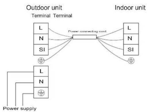
flowchart
graph TD
    A["Outdoor unit"] --> B["Terminal"]
    B --> C["Power connecting cord"]
    D["Indoor unit"] --> E["Terminal"]
    E --> F["Power connecting cord"]
    G["Power supply"] --> H["Terminal"]
    H --> I["Power connecting cord"]
    J["L/N/SI"] --> K["Power connecting cord"]
    L["L/N/SI"] --> K
    M["L/N/SI"] --> K
    N["L/N/SI"] --> K
18K/24K/36K

flowchart
graph TD
    A["Power connecting cord"] --> B["Terminal L"]
    A --> C["Terminal N"]
    A --> D["Terminal SI"]
    E["Power supply"] --> F["W"]
    E --> G["V"]
    E --> H["U"]
    E --> I["N"]
    E --> J["⊕"]
    K["Outdoor unit"] --> A
    L["Indoor unit"] --> A
    M["Indoor unit"] --> C
    N["Indoor unit"] --> L
    O["Indoor unit"] --> C
    P["Indoor unit"] --> L
    Q["Indoor unit"] --> C
    R["Indoor unit"] --> L
    S["Indoor unit"] --> C
    T["Indoor unit"] --> L
    U["Indoor unit"] --> C
    V["Indoor unit"] --> L
    W["Indoor unit"] --> C
    X["Indoor unit"] --> L
    Y["Indoor unit"] --> C
    Z["Indoor unit"] --> L
    AA["Indoor unit"] --> C
    AB["Indoor unit"] --> L
    AC["Indoor unit"] --> C
    AD["Indoor unit"] --> L
    AE["Indoor unit"] --> C
    AF["Indoor unit"] --> L
    AG["Indoor unit"] --> C
    AH["Indoor unit"] --> L
    AI["Indoor unit"] --> C
    AJ["Indoor unit"] --> L
    AK["Indoor unit"] --> C
    AL["Indoor unit"] --> L
    AM["Indoor unit"] --> C
    AN["Indoor unit"] --> L
    AO["Indoor unit"] --> C
    AP["Indoor unit"] --> L
    AQ["Indoor unit"] --> C
    AR["Indoor unit"] --> L
    AS["Indoor unit"] --> C
    AT["Indoor unit"] --> L
    AU["Indoor unit"] --> C
    AV["Indoor unit"] --> L
    AW["Indoor unit"] --> C
    AX["Indoor unit"] --> L
    AY["Power connecting cord"] --> Z
42K/48K/60K
1. Safety Notice
WARNING
- Installation should be left to the dealer or another professional person. (Improper installation may cause water leakage, electrical shock, or fire.)
- Install the unit according to the instruction given in this manual. (Incomplete installation may cause water leakage, electrical shock, or fire.)
- Be sure to use the supplied or specified installation parts. (Use of other parts may cause the unit to come to lose, water leakage, electrical shock, or fire.)
• Install the air conditioner on a solid base that can support the unit weight. (An inadequate base or incomplete installation may cause injury in the event the unit falls off the base.) - Electrical work should be carried out in accordance with the installation manual and the local national electrical wiring rules or code of practice.
(Insufficient capacity or incomplete electrical work may cause electrical shock or fire.)
- Be sure to use a dedicated power circuit. (Never use a power supply shared by another appliance.)
- For wiring, use a cable long enough to cover the entire distance with no connection, do not use an extension cord.
- Do not put other loads on the power supply, use a dedicated power circuit. (Failure to do so may cause abnormal heat, electric shock or fire.)
- Use the specified types of wires for electrical connections between the indoor and outdoor units. (Firmly clamp the interconnecting wires so their terminals receive no external stresses.)
- Incomplete connections or clamping may cause terminal overheating or fire.
- After connecting interconnecting and supply wiring be sure to shape the cables so that they do not put undue force on the electrical covers or panels. (Install covers over the wires, incomplete cover installation may cause terminal overheating, electrical shock or fire.)
- When installing or relocating the system, be sure to keep the refrigerant circuit free from substances other than the specified refrigerant (R410A), such as air. (Any presence of air or other foreign substance in the refrigerant circuit causes an abnormal pressure rise or rupture, resulting in injury.)
- If any refrigerant has leaked out during the installation work, ventilate the room. (The refrigerant produces a toxic gas if exposed to flames.)
• After all installation is completed, check to make sure that no refrigerant is leaking out. (The refrigerant produces a toxic gas if exposed to flames.) - When carrying out piping connection, take care not to let air substances other than the specified refrigerant go into refrigeration cycle. (Otherwise, it will cause lower capacity, abnormal high pressure in the refrigeration cycle, explosion and injury.)
- Be sure to establish an earth. Do not earth the unit to a utility pipe, arrester, or telephone earth. Incomplete earth may cause electrical shock. (A high surge current from lightning or other sources may cause damage to the air conditioner.)
- An earth leakage circuit breaker may be required depending on site condition to prevent electrical shock. (Failure to do so may cause electrical shock.)
- Disconnect the power supply before completion of wiring, piping, or checking the unit.
- When moving the indoor unit and outdoor unit, please be careful. Do not make the outdoor unit incline over 45 degree. Please avoid to be hurt by the sharp edge of the air conditioner.
• Install the remote controller: Be sure that the length of the wire between the indoor unit and remote controller is within 40 meters.
CAUTION
- Do not install the air conditioner in a place where there is danger of exposure to inflammable gas leakage. (If the gas leaks and builds up around the unit, it may catch fire.)
- Establish drain piping according to the instructions of this manual. (Inadequate piping may cause flooding.)
-
Tighten the flare nut according to the specified method such as with a torque wrench. (If the flare nut is tightened too hard, the flare nut may crack after a long time and cause refrigerant leakage.)
-
The Tools and Instruments for Installation
| Number | Tool | Number | Tool |
| 1 | Standard screwdriver | 8 | Knife or wire stripper |
| 2 | Vacuum pump | 9 | Gradienter |
| 3 | Charge hose | 10 | Hammer |
| 4 | Pipe bender | 11 | Churn drill |
| 5 | Adjustable wrench | 12 | Tube expander |
| 6 | Tube cutter | 13 | Inner hexagon spanner |
| 7 | Cross head screw-driver | 14 | Tape measure |
3. The Installation of the Indoor Unit

CAUTION
During installation, do not damage the insulation material on the surface of the indoor unit.
3.1 Before installation
- When moving the unit during or after unpacking, make sure to lift it by holding its lifting lugs. Do not exert any pressure on other parts, especially the refrigerant piping, drain piping and flange parts.
- Wear protective gears (gloves and so on) when install the unit.
• Install correctly according to the installation manual. - Confirm the following points:
○ Unit type/Power supply specification
○ Pipes/Wires/Small parts
○ Accessory items
ACCESSORY ITEMS
| Accessory | Q'ty | Purpose | |
| Washer (M10) |  | 8 | For Unit Hanging |
| Paper Pattern |  | 1 | For Unit Hanging And Adjustment |
| Insulation |  | 1 | For Refrigerant Piping Connection |
| Insulation |  | 1 | |
| Cord Clamp |  | 10 | For Fixing Of Pipe Cover |
| Drain Hose |  | 1 | For Drain Pipe Connection |
| Hose Clamp |  | 2 | For Joint Socket Connection |
| Heavy Insulation |  | 2 | For Drain Hose Cover |
| Joint Socket |  | 1 | For Drain Hose Connection |
| Jump Ring |  | 1 | For Drain Hose Connection |
| Plastic Sheath |  | 1 | For Drain Hose And Piping Connection |

3.2 Installation location
- Select the suitable areas to install the unit under approval of the user.
• The air passage is not blocked. - Condensate can drain properly.
- The ceiling is strong enough to bear the weight of the indoor unit.
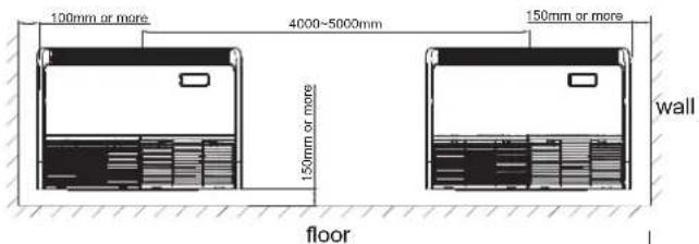
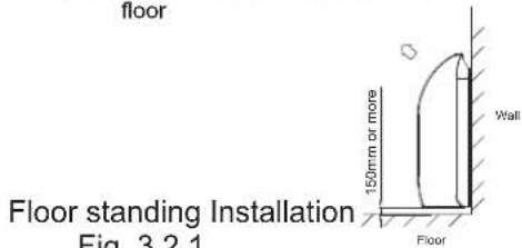
- Sufficient clearance for maintenance and servicing is ensured.(See Fig.3.2.1)
- Piping between the indoor and outdoor units is within the allowable limits.(refer to the installation of the outdoor unit)
- The indoor unit, outdoor unit, power supply wiring and transmission wiring is at least 1 meter away from televisions and radio, to prevents image interference and noise in electrical appliances. (Noise may be generated depending on the conditions under which the electric wave is generated, even if a one-meter allowance is maintained.)
- Use suspension bolts to install the unit, check whether or not the ceiling is strong enough to support the weight of the unit. If there is a risk that the ceiling is not strong enough, reinforce the ceiling before installing the unit.
- If there are 2 units of wireless type, keep them away for more than 6m to avoid malfunction due to cross communication.
- When plural indoor units are installed nearby, keep them away for more than 4-5m.
Space for installation and service

3.3 Installation
According to the actual installation space, install it in the ceiling or on the floor.
3.3.1 Suspension bolts
(1) Consider the pipe direction, wiring and maintenance carefully, and choose the proper direction and location for installation.
(2) Install the suspension bolts as shown in Fig. 3.3.1 below.

Fig. 3.3.1 Fixing the suspension bolts
3.3.2 The position of the suspension bolts and the pipes
(1) Mark the positions of the suspension bolts positions of the refrigerant pipes and the drain pipes.
(2) The dimension are shown below.

| Capacity(Btu/h) | A | B |
| 9K,18K, 24K | 990 | 912 |
| 36K | 1285 | 1207 |
| 42K,48K, 60K | 1580 | 1502 |
Fig. 3.3.2 Suspension bolts
※The outlet through which the pipings are taken out is available in three directions.
※Pipes can be taken out in 3 directions(rear, right or top).(See fig.3.3.3)
Cut out holes using nippers, etc.
Cut out holes to taken out pipes along the cutoff line on the rear cover.
Cut out the top face cover aligning to the piping position.
When taking pipe out to right-hand side, cut out a hole along the groove at the inside of the side panel.
After installing pipes and wires, seal clearances around pipes and wires with putty, etc. to shut off dust.
Make sure to install the covers at rear and top in order to protect the inside of unit from intrusion of dust or protect wires from damages by sharp edges. When taking them out to the right-hand side, remove burrs or sharp edges from the cutout.
UNIT:mm

Fig. 3.3.3
3.3.3 Indoor unit preparation
(1) Remove the air return grille.
Slide stoppers (4 places) of the catches, then remove the screws(4 or 6 places).

Fig. 3.3.4
(2)Remove side panel.
Remove the screw and detach the side panel by sliding it toward the direction indicated by the arrow mark.

Fig. 3.3.5
(3) Remove the hanging plate.
Remove the screw and then fixing bolts.
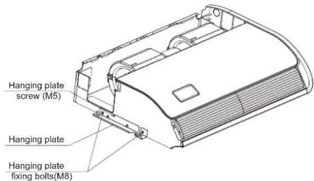
Fig. 3.3.6 Suspension bolts and nuts
3.3.4 Install the indoor unit Ceiling type installation
(1)Select the suspension bolt locations and the pipe hole location.
i. Use enclosed paper pattern as a reference, and drill the holes for the suspension bolts and pipe.
Note: Decide the locations based on the direct measurements.
ii.Once the locations are properly placed, the paper pattern can be removed.
2) Install the suspension bolts in place.
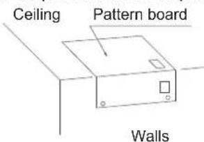
Fig. 3.3.7
(2)
- Place the left hanger bracket on the nuts and washers of the suspension bolts.
- Make sure that the left hanger bracket has been fixed on the nuts and washers securely, install the right hanger bracket suspension hook on the nuts and washers.
(When installing the indoor unit, you can slightly remove the suspension bolts.)
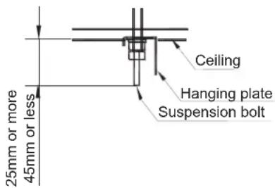
Fig. 3.3.8
(3) Fix with 4 suspension bolts, which can endure load of 530N.
(4) Check the measurements of the length of the suspension bolts.
(5) Fasten the hanging plate onto the suspension bolts.
(6) Install the unit to the hanging plate.
i.Slide the unit from front side to get it hanged on the hanging plate with bolts.
ii.Fasten the four fixing bolts(M8:2 each on the left and right sides)firmly.
iii.Fasten the two screws(M5:1 each on the left and right sides.)

Fig. 3.3.9
Floor standing type installation
(1) Select the suspension bolt locations and the pipe hole location.
i. Use enclosed paper pattern as a reference, and drill the holes for the suspension bolts and pipe.
Note:
Decide the locations based on the direct measurements.
ii. After the locations are properly placed, the paper pattern can be removed.
(2) Install the suspension bolts in place.

Fig. 3.3.10
(3) Fix with 4 suspension bolts, and fasten the four fixing bolts(M8:2 each on the left and right sides) firmly.
(4) Fasten the two screws of Air Intake Grille(M5:1 each on the left and right sides).
3.3.5 The horizon adjustment of the indoor unit
(1) Make sure that the hanger bracket is fixed by the nut and the washer.
(2) Adjust the height of the unit.
(3) Check the unit is horizontally level.
*To ensure smooth drain flow, install the unit with a descending slope(0-3mm) toward the drain outlet.
(4) After the adjustment, tighten the nut and smear the thread locker on the suspension to prevent the nuts from loosening.
CAUTION
During the installation, please cover the unit with the plastic cloth to keep it clean.
4. Refrigerant Pipe

DANGER
Use the R410A refrigerant. When carrying on the leakage check and test, do not mix in the oxygen, the acetylene and flammable and the virulent gas, for these gases are quite dangerous, and may possibly cause explosion. It is suggested that the compressed air, the nitrogen or the refrigerant be used to perform these experiments.
4.1 The Pipe Material
(1) Prepare the copper pipe on the spot.
(2) Choose dustless, non-humid, clean copper pipe. Before installing the pipe, use nitrogen or dry air to blow away the tube dust and impurity.
(3) Choose the copper pipe according to Fig. 4.2.
4.2 The Connection of the Pipe
(1) The connection positions of the pipe are shown in Fig. 4.1 and Fig. 4.2.
unit:(mm)

Fig. 4.1 The connection positions of the tube
| Capacity (Btu/h) | Gas pipe | Liquid pipe | Drain pipe |
| 18K | 12.7 | 6.35 | De25 |
| 24K | 15.88 | 9.52 | De25 |
| 36K,42K,48K, 60K | 19.05 | 9.52 | De25 |
Fig. 4.2 The pipe diameter
The pipe can be connected from three different directions.(rear, right, top)
when the pipe is routed through the back.
If the bracket is removed, piping work will become easy.
After piping, reinstall the removed bracket.

natural_image
Technical line drawing of a mechanical housing or enclosure component (no text or symbols)When the pipe is routed through the back. Cut the removed top cover, and install to the rear panel instead of rear cover.
(2) As shown in Fig. 4.3, screw up the nuts with 2 spanners.

natural_image
Illustration of hands performing a rope knotting operation with an arrow indicating motion (no text or symbols)| Tube size | Torque (N.m) |
| 6.35mm | 20 |
| 9.52mm | 40 |
| 12.7mm | 60 |
| 15.88mm | 80 |
| 19.05mm | 100 |
Fig. 4.3 Screw up the nut torque
(3) After finishing connecting the refrigerant pipes, keep it warm with the insulation material.
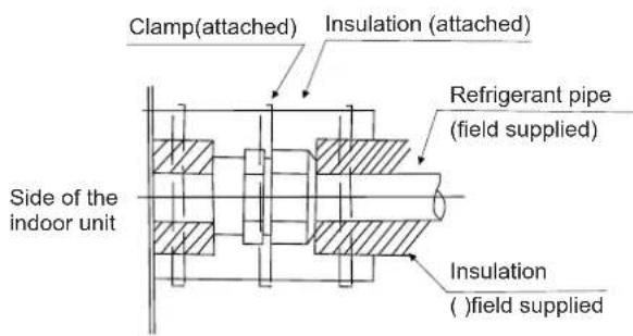
Fig. 4.4 Piping insulation procedure

CAUTION
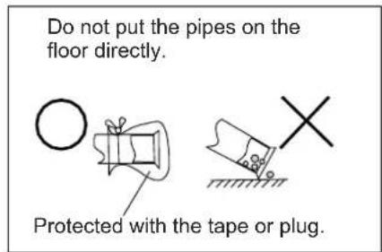
- The pipe go through the hole with the seal.
- Do not put the pipes on the floor directly.
5. Drain piping
Install the drain piping •
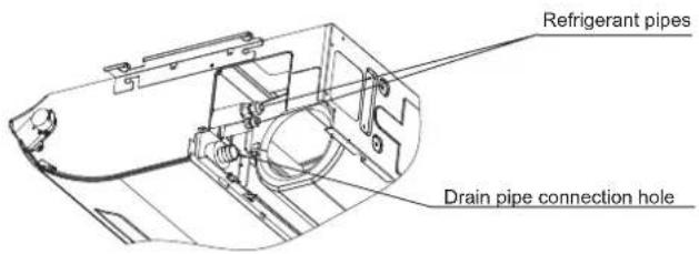
• Make sure the drain works properly.
- The diameter of drain pipe connection hole should be same as that of the drain pipe.
- Keep the drain pipe short and sloping down wards at a gradient of at least 1/100 to prevent air pockets from forming.
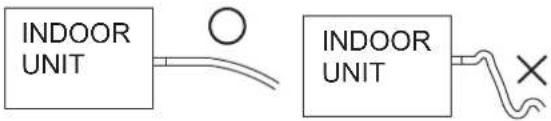

CAUTION
Water accumulating in the drain piping can cause the drain to clog.
- To keep the drain tube from sagging, space hanging wires every 1 to 1.5 ~m .
- Use the drain hose and the clamp. Insert the drain hose fully into the drain socket and firmly tighten the drain hose and warm-keeping material with the clamp.
- The two areas below should be insulated because condensation may form there causing water to leak.
- Drain piping passing indoors
- Drain sockets.
- Referring the figure below, insulate the drain socket and drain hose using the included large sealing pad.

CAUTION
Drain piping connections
- Do not connect the drain directly to sewage pipes that smell of ammonia. The ammonia in the sewage might enter the indoor unit through the drain pipes and corrode the heat exchanger.
- Do not twist or bend the drain hose, so that excessive force is not applied to it.
This type of treatment may cause leaking.
- After piping work is finished, check drainage flows smoothly.
- Gradually insert approximately 1000 cc of water into the drain pan to check drainage in the manner described below.
- Gradually pour approximately 1000 cc of water from the outlet hole into the drain pan to check drainage.
- Check the drainage.

Sealing material Sealing material

6. Electrical wiring

CAUTION
- When clamping the wiring, use the included clamping material as shown in the FIG.6.1 to prevent outside pressure being exerted on the wiring connections and clamp firmly.
- When doing the wiring, make sure the wiring is neat and does not cause the control box lid to stick up, then close the cover firmly. When attaching the control lid, make sure you do not pinch any wires.
- Outside the machine, separate the weak wiring(remote controller and transmission wiring) and strong wiring (earth and power supply wiring) at least 50 mm so that they do not pass through the same place together. Proximity may cause electrical interference. Malfunction, and breakage.

WARNING
- If the fuses burn up, please call the service agency to instead it. Please do not instead by yourself, or else may result in accident, for example shock.
(1) Remove the screws on the control box.
(2) Connect the power cord and earth wire to the main terminal.
(3) The remote control wire to the subsidiary terminal box according to electric wiring diagram.
(4) Connect the power supply of the indoor and outdoor units to the main terminal.
(5) Tie the wire in the control box with the clamp tightly.
(6) After finishing the wiring, seal the wiring hole with the sealing material (with the lid) to prevent the condensed water and insects entering.
7. Attaching the air return grille
- The air return grille must be attached when electric cabling work is completed.
(1) Fix the air return grille onto the indoor unit with screws supplied as accessories(4 pieces).
(2) Close the air return grille.
This completes the unit installation work.

natural_image
Technical line drawing of a portable air conditioner unit with ventilation grilles and a small inset showing airflow direction (no text or symbols)8. The Installation of the Outdoor Unit
8.1 Installation sites
Avoid
- Direct sunlight
- Aisle Or sideway
- Thick Oil fog
- Wet Or Uneven place
- Container With Flammable materials
• Near Heat Source/ventilation fan
You should
- Place it in cool temperature.
- Place it in an area with good ventilation.
- Have desired space for air inlet, outlet and maintenance. (Figure 8.1)
- Make a strong base(10X40cm ^2 board made of concrete or alike). The appliance should be placed not less than 10 cm high to avoid being wet or corroded. Otherwise, it may cause damage to the appliance or reduce its life time. (Figure 8.2)
- Fix the base with hook bolts or alike to reduce vibration and noise.

flowchart
graph TD
    A["Indoor unit"] --> B["Tube length L"]
    B --> C["Outdoor unit"]
    C --> D["Height difference H"]
    D --> E["Model"]
    E --> F["Max. Tube length(L)"]
    F --> G["18K"]
    G --> H["30(m)"]
    H --> I["24K/36K/42K/48K/60K"]
    I --> J["50(m)"]
    J --> K["Max. Height difference(H)"]
    K --> L["15(m)"]
    L --> M["Add. Refrigerant (exceed 5m)"]
    M --> N["15(g/m)"]
    N --> O["30(m)"]
    O --> P["35(g/m)"]
Fig.8.3
If the total tube length is between 5m and 50m (Max. length), an additional refrigerant can be added. It's not necessary to add compressor oil. (Figure 8.3)

Fig. 8.1

Fig.8.2
8.2 Installation of the outdoor unit
Firstly select the installation site and fix the outdoor unit. If it needs to be fixed onto the wall, make sure that the wall and the supporting rack is strong enough to hold the weight of the appliance.
Wiring instruction for outdoor unit
- Release the setscrews of the electric cover, remove the electric cover(If the valve cover is there either, please release it.)
- Connect the indoor unit wiring to the outdoor unit panel according to the electric wiring diagrams.
- Be sure to make each wire allowing 10cm longer than the required length for wiring.
- Ground the unit following local electrical regulations.
- Check the wiring with the wiring diagrams and make sure it's well connected. Fix the wiring with clips and reinstall the electric cover.
9. Refrigerant Tubing
9.1 Flaring with Tube Expander
Note: A good flare have the following characteristics:
- Inside surface is glossy and smooth.
- Edge is smooth.
- Tapered sides are of uniform length.
- Remove the burrs at the end of the copper tube with a tube reamer or file. When reaming, hold the tube bend downward and be sure that no copper scraps fall into the tube. This process is important and should be done carefully to make a good flare.(Figure 9.1,9.2)
- Remove the flare nut from the unit and be sure to mount it on the copper tube.
- Make a flare at the end of copper tube with a flare tool.(Figure 9.3)
9.2 Connecting Tubing between Indoor and Outdoor Units
- Be sure to apply a sealing cap or water-proof tape to prevent dust or water from getting into the tubes before they are used.
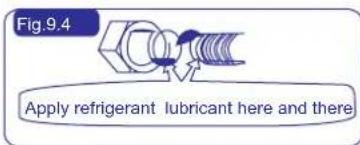
- Be sure to apply refrigerant lubricant to the matching surfaces of the flare and union before connecting them together. This is effective for reducing gas leaks.(Figure 9.4)
- For proper connection, align the union tube and flare tube straight with each other, then screw in the flare nut lightly to obtain a smooth match. (Figure 9.5)
- Tighten the setscrew with torque wrench to prevent leak of refrigerant. Carefully test leak before running the appliance.
9.3 Heat Insulation of the Refrigerant Tube
To avoid loss of heat and in prevention of the ground being wet by condensed water, all refrigerant tubes must be insulated with suitable insulating materials whose minimum thickness will be 6 mm. (See Figure 9.6)
9.4 Taping the Tubes
Note: Do not wind the armoring tape too tightly because this will decrease the heat insulation effect. Also be sure the condensation drain hose splits away from bundle and drips clear of the unit and the tubing.
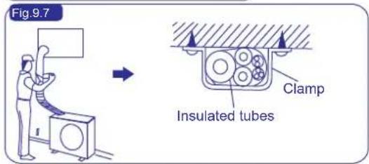
- The two refrigerant tubes (and electrical wire if local codes permit) should be taped together with white armoring tape. The drain hose may also e included and taped together as a bundle with the tubing.
- Wrap the tape from the bottom of the outdoor unit to the top of the tubing where it enters the wall. As you wrap the tubing, overlap half of each previous tape. (See Figure 9.7)
- Clamp the tubing bundle to the wall, using one clamp approx. every 120 cm.
9.5 Finishing the Installation
After completion of wrapping and insulation, seal the hole on the wall with suitable sealant against wind and rain.
10. Air Purging and Test Run
Air and moisture remaining in the refrigerant system have undesirable effects.
Therefore, they must be purged completely following the steps.
10.1 Air Purging with a Vacuum Pump (See Figure 10.1, Figure 10.2)
(1) Check that each tube (both narrow and wide tubes between the indoor and outdoor units) have been properly connected and all wiring for the test run has been completed. Note that both narrow and wide tube valves on the outdoor unit are kept closed at this stage.
(2) Using an adjustable wrench or box wrench, remove the bonnet from the service valve.
(3) Connect a vacuum pump and service valve together tightly.
(4) Turn on the vacuum pump and till the pressure is lower than 15Pa(or 1.5 × 10^-4 bar) for 5 minutes.
(5) With the vacuum pump still running, demount tube of vacuum pump from the service valve. Then stop the vacuum pump.
(6) Replace the bonnet on the service valve and fasten it securely with an adjustable wrench or box wrench.
(7) Using an adjustable wrench or box wrench, remove the bonnet of both narrow and wide valve.
(8) With the hex wrench, turn the wide and narrow tube valves stem counter clockwise to fully open the valves.
(9) Replace the bonnets on the wide and narrow valves and fasten it securely with an adjustable wrench or box wrench.
10.2 Leak Test
- Leak test all joints and valves of the indoor unit and outdoor unit with liquid soap. Checking of the orifice cap shouldn't be less than 30 seconds. Clean the liquid soap after the test in case that the color of the copper tube may change for erode.
10.3 Tidy up the Tubing
- If the leak test turns out to be all right, preserve heat the joints of the indoor unit.
- Straighten the connecting tubes and make them flush and fixed to the wall. Seal the space around the hole in the wall through which the tubes come out with gypsum.
10.4 Test Run
WARNING
- Only after all the checking points have been checked the unit can be operated.
(A) Check and make sure that the resistance of the terminal to ground is more than 2MΩ otherwise, you cannot operate the unit before the electricity leakage point is found and repaired.
(B) Check and make sure that the stop valve has been opened before operating the unit.
(C) Make sure that turn on electric power 6 hours before operating the unit.
- Make sure the power and unit run well then plug in.
- Turn on the appliance and adjust it to Cooling or Heating mode according to the room temperature. Set temp. at 16°C when cooling mode and 30°C when heating mode. Check if the appliance can run well.
- Installation of the appliance is generally finished after the above operations are done. If you still have any trouble, please contact local technical service center of our company for further information.
● Pay attention to the following items while the system is running.
(A) Do not touch any of the parts by hand at the discharge gas side, since the compressor chamber and the pipes at the discharge side are heated higher than 90°C.
(B) DO NOT PUSH THE BUTTON OF THE MAGNETIC SWITCH(ES). It will cause a serious accident.
(C) Use remote controller to operate, and check whether room temperature and function well.
After test, turn off the electric power.





10.5 Common
WARNING
- Use an ELB (Electric Leakage Breaker). If not used, it will cause an electric shock or a fire.
- Do not operate the system until all the check points have been cleared.
(A) Check to ensure that the insulation resistance is more than 2 megohm, by measuring the resistance between ground and the terminal of the electrical parts. If not, do not operate the system until the electrical leakage is found and repaired.
(B) Check to ensure that the stop valves of the outdoor unit are fully opened and then start the system.
| Model Capacity(Btu/h) | Power Supply | ELB | Power Source Cable Size | Transmitting Cable Size | |
| Nominal Current(A) | Nominal Sensitive Current (mA) | En60 335-1 | En60 335-1 | ||
| 18K | 220-240V ~,50Hz | 20 | 30 | 3 × 2.5mm^2 | 4 × 1.5mm^2 |
| 24K | 220-240V ~,50Hz | 32 | 30 | 3 × 2.5mm^2 | 4 × 1.5mm^2 |
| 36K | 220-240V ~,50Hz | 40 | 30 | 3 × 4.0mm^2 | 4 × 1.5mm^2 |
| 42K/48K/60K | 380-415V 3N~,50Hz | 32 | 30 | 5 × 2.5mm^2 | 4 × 1.5mm^2 |
Max. Running Current(A):REFER TO NAMEPLATE
NOTES:
1) Follow local codes and regulations when selecting field wires, and all the above are the minimum size.
2) The wire sizes marked in the table are selected at the maximus current of the unit according to the European Standard, En60 335-1. Use the wires which are not lighter than the ordinary polychloroprene sheathed flexible cord (code designation H07RN-F).
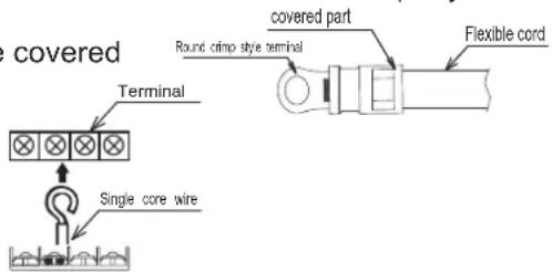
When connecting the terminal block using flexible cord, make sure to use the round crimp-style terminal for connection to the power supply terminal block.
Place the round crimp-style terminals on the wires up to the covered part and secure in place.
When connecting the terminal block using a single core wire, be sure to perform curing.
3) When transmitting cable length is more than 15 meters, a larger wire size should be selected.
4) Use a shielded cable for the transmitting circuit and connect it to ground.
5) In the case that power cables are connected in series, add each unit maximum current and select wires below.
Selection According to EN60 335-1
| Current i (A) | Wire Size (mm2) |
| i ≤ 6 | 0.75 |
| 6 < i ≤ 10 | 1 |
| 10 < i ≤ 16 | 1.5 |
| 16 < i ≤ 25 | 2.5 |
| 25 < i ≤ 32 | 4 |
| 32 < i ≤ 40 | 6 |
| 40 < i ≤ 63 | 10 |
| 63 < i | * |
*In the case that current exceeds 63A, do not connect cables in series.

natural_image
Pure electrical circuit lines without any symbolsCorrect Disposal of this product
This marking indicates that this product should not be disposed with other household wastes throughout the EU. To prevent possible harm to the environment or human health from uncontrolled waste disposal, recycle it responsibly to promote the sustainable reuse of material resources. To return your used device, please use the return and collection systems or contact the retailer where the product was purchased. They can take this product for environmental safe recycling.
Hisense
natural_image
Technical line drawing of a front-end air conditioning unit with a circular fan blade and side panel (no text or symbols)18K,24K,36K,42K
natural_image
Technical line drawing of a dual-panel air conditioner unit with fan blades (no text or symbols)48K,60K
Composition of the Air-conditioner
Fig. 3.3.4
natural_image
Technical line drawing of a mechanical component with no visible text or symbolsnatural_image
Illustration of hands using a tool to lift a rope, with an arrow indicating upward motion (no text or symbols)| Diametro tubo | Coppia di serraggio N.m |
| 6.35mm | 20 |
| 9.52mm | 40 |
| 15.88mm | 80 |
| 19.05mm | 100 |
natural_image
Technical line drawing of a portable air conditioner unit with ventilation grilles and a small inset showing airflow path (no text or symbols)natural_image
Pure electrical circuit lines without any symbolsnatural_image
Technical line drawing of a front-mounted air conditioning unit with a circular fan blade (no text or symbols)18K,24K,36K,42K

natural_image
Technical line drawing of a dual-panel HVAC unit fan with visible blades and ventilation patterns (no text or symbols)Fig. 3.3.10
natural_image
Technical line drawing of a mechanical component or housing (no text or symbols visible)natural_image
Illustration of hands performing a rope knotting operation with an arrow indicating motion (no text or symbols)| Tamaño del conducto | Par de apriete (N.m) |
| 6.35mm | 20 |
| 9.52mm | 40 |
| 12.7mm | 60 |
| 15.88mm | 80 |
| 19.05mm | 100 |
Fig. 4.3 Par de apriete de las tuercas a enroscar
natural_image
Simple line drawings of a bell and a drop with a cross symbol (no text or labels)natural_image
Line drawing of a portable air conditioner unit with ventilation grilles and a small inset showing airflow path (no text or symbols)natural_image
Pure electrical circuit lines without any symbolsnatural_image
Technical line drawing of a front-mounted air conditioning unit with a circular fan blade (no text or symbols)18K,24K,36K,42K

natural_image
Technical line drawing of a dual-panel HVAC fan unit with ventilation patterns (no text or symbols)48K,60K
Notas:
Passo 1
Passo 2
Redefina o filtro
natural_image
Technical line drawing of a mechanical housing or enclosure component (no text or symbols)natural_image
Illustration of hands using a tool to lift a rope, with an arrow indicating upward motion (no text or symbols)| Tamanho do tubo | Torque N.m) |
| 6.35mm | 20 |
| 9.52mm | 40 |
| 12.7mm | 60 |
| 15.88mm | 80 |
| 19.05mm | 100 |
Figura 4.3 Aperte o torque da porca
natural_image
Technical line drawing of a portable air conditioner unit with ventilation grilles and a small inset showing airflow direction (no text or symbols)natural_image
Pure electrical circuit lines without any symbolsnatural_image
Technical line drawing of a front-mounted air conditioning unit with a circular fan blade (no text or symbols)18K,24K,36K,42K
natural_image
Technical line drawing of a dual-panel air conditioner unit with fan blades (no text or symbols)48K,60K
Hinweis:
natural_image
Technical line drawing of a mechanical housing or enclosure component (no text or symbols visible)natural_image
Illustration of hands using a tool to lift a cable or cable (no text or symbols present)| Schlauchgröße | Drehmoment (N.m) |
| 6.35mm | 20 |
| 9.52mm | 40 |
| 12.7mm | 60 |
| 15.88mm | 80 |
| 19.05mm | 100 |
natural_image
Simple line drawings of a bell and a drop with a cross symbol (no text or labels)natural_image
Technical line drawing of a portable air conditioner unit with ventilation grilles and a small inset showing airflow direction (no text or symbols)natural_image
Pure electrical circuit lines without any symbols- USE AND INSTALLATION INSTRUCTIONS
- Features of Ceiling&Floor Air Conditioner
- Contents
- Operation Manual
- Diagram of Refrigerant Cycle & Wiring
- Installation and Maintenance
- NOTE
- Alert Symbols:
- Caution Statements
- DANGER
- WARNING
- CAUTION
- Composition of the Air-conditioner
- Remote controller(optional)
- Special remarks
- minutes protect after compressor stop
- Troubleshooting
- If Trouble Still Remains ...
- No Operation
- Not Cooling or Heating Well
- This is Not Abnormal
- ● Smells from indoor unit
- ● Sound from Deforming Parts
- ● Steam from Outdoor Heat Exchanger
- ● Dew on Air Panel
- ●Refrigerant Flow Sound
- 5.Filter removing and installing
- ●Removing filter from air return grille
- Reset the filter
- Safety Notice
- The Installation of the Indoor Unit
- Before installation
- ACCESSORY ITEMS
- Installation location
- Installation
- Indoor unit preparation
- Install the indoor unit Ceiling type installation
- (2)
- Floor standing type installation
- Refrigerant Pipe
- The Pipe Material
- The Connection of the Pipe
- Drain piping
- Electrical wiring
- Attaching the air return grille
- The Installation of the Outdoor Unit
- Installation sites
- Avoid
- You should
- Installation of the outdoor unit
- Wiring instruction for outdoor unit
- Refrigerant Tubing
- Flaring with Tube Expander
- Connecting Tubing between Indoor and Outdoor Units
- Heat Insulation of the Refrigerant Tube
- Taping the Tubes
- Finishing the Installation
- Air Purging and Test Run
- Air Purging with a Vacuum Pump (See Figure 10.1, Figure 10.2)
- Leak Test
- Tidy up the Tubing
- Test Run
- ● Pay attention to the following items while the system is running.
- Common
- NOTES:
- Correct Disposal of this product
- Hisense
- Notas:
- Hinweis:
Brand : HISENSE
Model : AUV105UR4RAB4
Category : Air conditioner