FM-215HDR - Monitor SWIT - Free user manual and instructions
Find the device manual for free FM-215HDR SWIT in PDF.


| Product Type | 21.5\" Professional 4K HDR Monitor |
| Model | SWIT FM-215HDR |
| Screen Size | 21.5 inches |
| Display Area | 476.064 x 267.786 mm |
| Resolution | 1920 x 1080 (Full HD) |
| Display Colors | 16.7 million (8-bit) |
| Maximum Brightness | 1000 cd/m² |
| Contrast Ratio | 1000:1 |
| Viewing Angle | 178° (H) / 178° (V) |
| Color Gamut | 97% DCI-P3 |
| Signal Processing | 18-bit internal |
| Video Inputs | 1x 12G/6G/3G/HD/SD-SDI, 3x 3G/HD/SD-SDI, 1x HDMI 2.0 (4K@60), 4x SDI (Quad Link) |
| Video Outputs | 1x 12G/6G/3G/HD/SD-SDI, 1x 3G/HD/SD-SDI |
| Audio | 3.5mm headphone jack, built-in speaker |
| Other Interfaces | RS-485 (UMD control), GPI (Tally), USB, RJ45 (Ethernet/IP control) |
| Power Supply | AC 100-240V 50/60Hz or DC 11-17V (battery plate V-mount/Gold-mount included) |
| Power Consumption | ≤60W |
| Operating Temperature | 0°C to +45°C |
| Storage Temperature | -15°C to +60°C |
| Net Weight (Monitor Only) | 7.28 kg |
| Net Weight (Flight Case) | 6.8 kg |
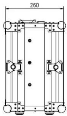
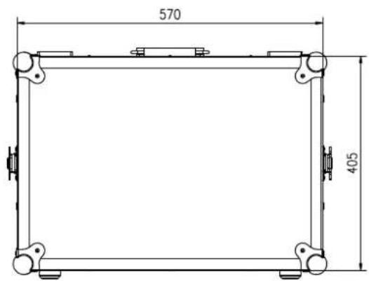
| Flight Case Dimensions (W x H x D) | 570 x 260 x 405 mm |
| Key Features | QLED panel, HDR support (PQ, HLG), 3D LUT calibration, auto calibration, waveform/vectorscope, false color, focus assist, zebra, UMD/TALLY, multiview (Quad/PBP/PIP), low latency mode, web control |
| Warranty | 2 years (excluding accidental damage, LCD pixel defects ≤3, improper use, disassembly) |
| Maintenance | Clean with dry soft cloth and LCD cleaner; avoid pressure on screen; do not use water or chemical cleaners |
Frequently Asked Questions - FM-215HDR SWIT
User questions about FM-215HDR SWIT
0 question about this device. Answer the ones you know or ask your own.
Ask a new question about this device
Download the instructions for your Monitor in PDF format for free! Find your manual FM-215HDR - SWIT and take your electronic device back in hand. On this page are published all the documents necessary for the use of your device. FM-215HDR by SWIT.
USER MANUAL FM-215HDR SWIT
User Manual
Please read this user manual throughout before using
Ver: A
Declaration
Any internal technology (including hardware equipment, software design and product trademark) of the product shall be protected by law, and any infringement of intellectual property rights of the product shall be investigated for legal liability.
All the brand and trademark in this product are protected by law, all other company's brand and trademark in this product are protected by their owner's law.
In order to better service majority users, SWIT products will keep improving and developing, SWIT keep the right to revise and improve this user manual without previous notice.
The warranty period of this product are two years, the following condition are not covered by the warranty:
(1) The appearance and the LCD panel are damaged by man-made out force;
(2) The amount of defective pixels are under three;
(3) Damage the product by using incompatible power adaptor;
(4) Damage the product due to violation operation;
(5) Disassemble the product when using;
(6) Other faults or damages not caused by design, technology, manufacture and quality.
* Any sales person have no right to provide extra warranty beyond these terms.
If you have any advises or requirements about our products during using, please feel free to contact with us via phone or E-mail.

This instruction manual applies to FM field monitors and the schematic is based on the exterior view of the FM-215HDR as an example. Any differences in specifications and appearance are explained in additional text in this manual.
SWIT Electronics Co., Ltd.
Address: 10 Hengtong Road, Nanjing Economic and Technological Development Zone, Nanjing 210038, P.R.China
Phone: +86-25-85805753
Fax: +86-25-85805296
Email: contact@swit.cc
http://www.swit.cc
Maintaince percautions
Warning
- To reduce the dangerous of fire or electric shock, do not expose the monitor in raining or wet place.
- The monitor will create noise when using near high-intensity magnetic field.
Precautions for power supply
- Please use the special power adapter specified by the original factory to avoid damage to the product.
- If other DC power supply is used, ensure that the voltage range, power supply and polarity of the power supply meet the requirements.
- In the following cases, please unplug the power cord and external battery of the product:
(A) If you have not used the product for A long period of time.
(B) If the power cord or power plug/socket is damaged.
(C) If the product is hit or dropped so that the shell is damaged.
Precautions for product use
- Please do not touch the screen surface directly with your fingers to avoid damage to the screen, and the oil on the skin will be difficult to remove if left on the screen.
- Please do not put pressure on the LCD screen, LCD screen is very delicate and fragile.
- Do not place the product in an unstable place, as the product may be seriously damaged due to falling.
Precautions for product cleaning
- Clean LCD screen, please use dry soft fabric with fluff and special liquid crystal cleaning agent, to remove dust and stains on the screen.
- Do not pressure when wiping the LCD screen surface.
- Please do not use water and other chemical cleaners to wipe the LCD screen surface, chemical agents may damage the LCD screen surface.
Content
Declaration 2
Maintaince perceptions 3
Content 4
Packing list 5
Introduction 5
Operation Instructions 6
Front panel 6
Back Panel 8
Flight Case 9
OSD 9
Menu Configuration 12
-
Exit & Status - Exit the main menu and display the current status of the monitor. 12
-
Input—Set the color of input video 13
-
Image setting—Setting for the picture preference 13
-
Color management—Setting about video colors 14
-
Scanning—Setting for picture scan, zoom, etc. 15
-
Control—Setting for TALLY, UMD, IP control to the monitor 16
-
Assist-Setting for Vector scope and Histogram patterns. 18
-
De-embed—Setting for video/audio analysis functions. 20
-
Auto calibration 21
-
System-User profile saving, firmware update. 23
-
Multiview setting 26
Appearance and Size 27
Specification 28
Supported standards: Signals of the following standards can be displayed on the monitor..... 29
Common Problems and Solutions 30
Packing list
| No. | Standard accessories | Quantities |
| 1 | Monitor | × 1 |
| 2 | Aluminium flying case | × 1 |
| 3 | Battery plate (V-mount & Gold-mount) | × 1 |
| 4 | Power cable | × 1 |
Introduction
This series of monitor adopts TFT-LCD thin film transistor + QLED quantum dot display composition, the resolution is up to 1920x1080, H178°/V178° ultra-wide viewing angle, 1000:1 contrast ratio, support 1 channel 12G/6G/3G/H D/SD-SDI input and output, 1 channel HDMI® 2.0 4K@60 input, and 3 channels 3G/HD /SD-SDI input and 1 channel 3G/HD/SD-SDI output, quad-link 4xSDI SQD /2SI 4Kp60/p50 input, 4-channel or 2-channel simultaneous picture display with headphone and speaker outputs.
Features:
■ 21.5" 1920X1080 Full HD QLED screen.
■ 1000nits high brightness backlight HDR monitor.
■ 97% DCI-P3 wide colour gamut ratio.
■ 4K/UHD interface (1x12G-SDI in/out, 1x HDMI® 2.0 4K@60 input).
■ 12GSDI, HDMI® Mixed Quad, Dual PBP and PIP Picture-in-Picture monitoring.
■ 12GSDI, HDMI ^® dual-screen PBP vertical monitoring.
■ Simultaneous display of HDR/SDR in multi-colour gamut for one signal.
- Read Payload ID to automatically set quantisation, dynamic contrast, colour gamut, etc.
■ 18bit high precision internal signal processing.
■ Zero audio/video delay (0.01 frame).
■ Built-in DelogSDR/HDR table for multiple cameras.
■ 16-channel audio de-embedded sound column display, optional 2-channel output.
■ Lissajous, 5.1 stereo phase map.
■ Support waveform selection display Y/Cb/Cr/R/G/B /RGB and single line selection mode.
■ Vector scope, R/G/B/Y histogram, bi-color focus assist.
■ 3DLUT (17 x 17 x 17) accurate color correction, Fully automatic colour correction, no computer required.
■ User 3DLUT uploaded via USB.
■ UMD dynamic source name and soft TALLY display (TSL 3.1/4.0), GPI control interface.
■ Composition ratio auxiliary line:4:3/13:9/14:9/15:9/16:9/1.85:1/2.35:1/2:1/2.39:1/Custom 1/Custom 2.
■ Support USB firmware upgrade and import Log file.(USB file system supports FAT 32 format only).
■ IP Webserver Web Control.
■ Support ECO mode.
Front panel
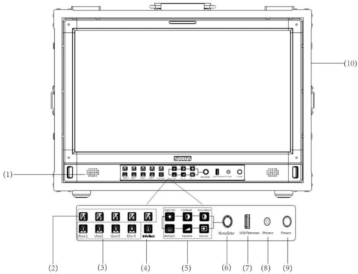
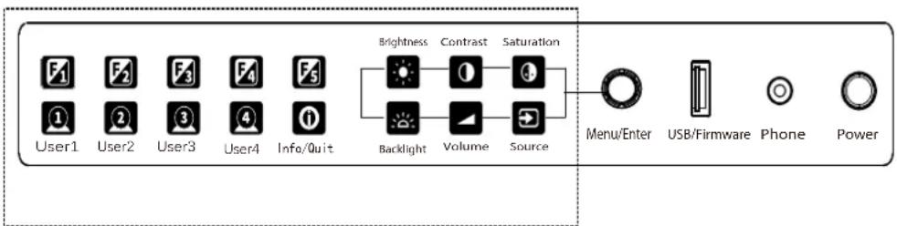
(1) Speaker: For SDI/ HDMI® embedded audio. (Will not work if earphone is plugged in)
(2) F1\~F5 function keys: Customize shortcut function keys. Users can set the shortcut keys to different functions according to their own requirements.
(3) User1\~User4:U1\~User shortcut key, which can be used to quickly enter the set user mode. Long press to save user settings. Please see details in “10. System”
(4) Info/Quit: Display setting item. Press "Info/Quit" button to display or turn off relevant status information and audio and video analysis function graph. When opening the menu, press "Info/Quit" to exit the menu with one click
(5)
Brightness Contrast Saturation      Backlight Volume Source Backlight Volume Source | Brightness: Adjust the brightness. -100~100 adjustable, default value is 0. | ||
| Contrast: Adjust contrast. -100~100 adjustable, default value is 0. | |||
| Saturation: Adjust saturation. -100~100 adjustable, default value is 0. | |||
| Backlight: Adjust the backlight. 0~100 adjustable, default value is 16. | |||
| Volume: Adjust the volume.0~100 adjustable, default value is 36. | |||
| Press Brightness, Contrast, Saturation, Backlight, Volume five shortcut keys confirm to select this option, and rotate Menu to adjust the corresponding item value directly. Press the button and automatically cancel the selection without operation within five seconds, and the button light will be off, long press to restore default values; Adjust the volume.0~100 adjustable, the default value is 36.Long press the volume button to mute. | |||
| SourceSDI 1SDI 2SDI 3SDI 44xSDI SQD4xSDI 2SIHDMI®Multiview | Source: Select the input source signal format.4xSDI SQD: Supports quad-link 4Kp60/p50 inputs4xSDI 2SI: Supports quad-link 4Kp60/p50 inputs | ||
(6) Menu/Enter: When no Menu is displayed, press the button directly to open the Main Menu; Rotate the knob to select different settings or adjust parameter values, press the knob to set;
(7) LUT/Firmware: Update firmware or import LUT files, Auto Calibration;
(8) PHONE: 3.5mm headphone jack is used to monitor the embedded audio signals of SDI and HDMI ^® ;
(9) Power: Power switch;
(10)Aluminium alloy flight case: to hold the monito.
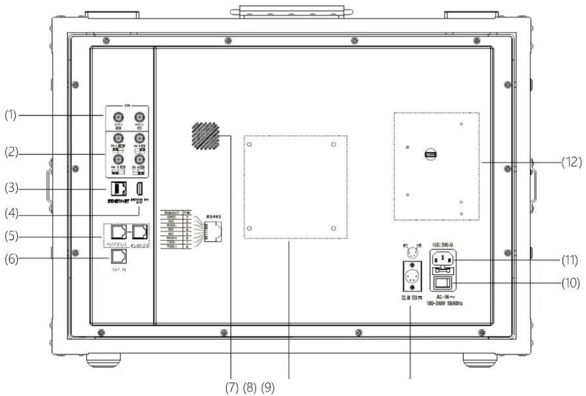
(1) SDI1 OUT: 12G/6G/3G/HD/SD-SDI
SDI2 OUT: 3G/HD/SD-SDI
(2) SDI1 IN: 12G/6G/3G/HD/SD-SDI
SDI2\~4 IN: 3G/HD/SD-SDI
(3) ETHERNET(Network interface): 1000M high-speed RJ45 Ethernet port,
for web external control
(4) HDMI® 2.0 4K@60 in: Will not display HDCP protected content
(5) RS485: TSL UMD control port
(6) GPI: GPI control port
(7) Fan
(8) VESA bracket mounting area
(9) DC IN: 12V\~17V
(10) AC switch: turns AC power on or off
(11) AC IN: 100V\~240V
(12) Battery grommet mounting area
(1)
(2)
(1) Flight case adapter plate:
(3) can be used to secure other equipment (e.g., PTZ, wireless transmission equipment, etc.)
(2) Flight case handle
(3) Rubber cushion for luggage base
OSD
(1)
(2)
(3)
(4)
(5)
(6)
(7)
TC 00:15:13:07
CAMERA 1
other
| Species | Frequency | | :--- | :--- | | R | 48 | | G | 44 | | B | 42 | | Y | 37.000 | | 13 | 940 | | 12 | 768 | | 11 | 512 | | 10 | 256 | | 9 | 64 | The data is presented as a table with two columns: 'Period' and 'Value'. The 'in phase' column contains the number of molecules per phase, and the 'in phase' column contains the number of molecules in phase. There are no additional data series or trends visible in the table.
(8)
(9)
(10)
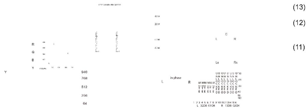
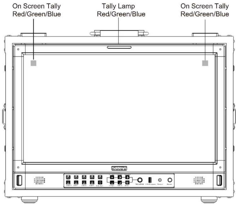
(1) TALLY Light
TALLY Light Controlled by GPI
(2) Time Code(SDI)
Under SDI input, the monitor can display Time code information (LTC, VITC1&2). If no Time code info is detected, it will display “TC UNLOCKED”. User can set function keys F1~F5 or GPI pins as “Time Code” to turn on or off this function.
(3) On screen TALLY
Control of the display signal via GPI
(4) Source ID/UMD
Display /UMD (TSL3.1/4.0), user can set in the UMD menu
(5) Colour gamut char
Used to monitor the colour fullness and fineness of the image, open the gamut chart to display the current video gamut, users can set the "Main Menu" - "Colour Management" - "Gamut". Current colour gamut.
(6) Histogram
The horizontal axis of the histogram indicates the brightness of the image, from left to right indicates the increase of brightness, the left side represents the darker area, the right side is the brighter area, the vertical axis of the histogram indicates the distribution of the number of pixels, the higher the vertical coordinate, the higher the brightness density.
The vertical axis of the histogram represents the distribution of the number of pixels, the higher the vertical coordinate, the higher the luminance density, users can set the front panel shortcut keys (F1\~F5) or GPI pins to the "Histogram" function, to turn on/off this function.
(7) Waveform
Used to display multiple signals sampled at the same rate, users can set the front panel short-cut keys (F1\~F5) or GPI pins to the "Waveform" function to turn on or off the Waveform graph and select different types of Waveform graphs; the parameters of the Waveform graph, such as the position, transparency, color, etc. are set in the "Waveform Setting" submenu. Waveform parameters, such as position, transparency, color, etc., can be set in the "Waveform Setting" submenu.
(8) Vectors
Used to monitor the colour, shape, outline, size and position of the image, etc. Users can set the front panel shortcut keys (F1 to F5) or GPI pins to the "Vector Graphics" function to turn on/off this function, and the display position, colour, transparency and other related parameters of the vector graphics are set in the "Vector Graphics Settings" submenu.
(9) Lissajous
Used to monitor the audio frequency analysis and phase amplitude difference determination, the user can set the front panel shortcut keys (F1\~F5) to "Li Sha Yu" function, open/close this function.
(10) Audio Meter
Used for monitoring audio information, users can set the front panel shortcut keys (F1\~F5) or GPI pins as the function of "Audio Meter" to turn on/off this function, the display position of the audio meter, the number of displayed channels, transparency and other related parameters are set in the Audio Settings sub-menu.
(11) Surround Phase
Monitor the sound source location of the full-space stereo sense of knowledge, Surround Phase default 5.1, the default 7, 8 channels, the user can be in the menu "data de-embedding" - "left / right channel", set the desired sound channels
(12) Eye pattern
Used to monitor the strength of the SDI signal quality, the larger the eye chart image, the stronger the signal quality.
(13) Colour checklist
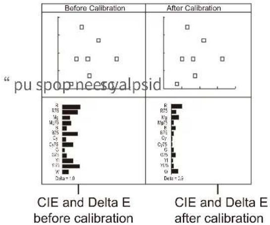
After auto calibration, the gamut value and colour difference ( E ) before and after calibration will be popped up. "Auto calibration"-"Measurement" pops up the gamut value and colour difference ( E ) of the last calibration and the current measurement.
Button operation
- Press the "Menu/Enter" knob, the menu pops up in the upper left corner of the screen, and the currently selected menu is highlighted in yellow.
- Rotate the "Menu/Enter" knob to select all kinds of sub-menu, the corresponding item is highlighted in yellow, press the "Menu/Enter" key, the sub-menu is selected and enter the parameter setting sub-menu.
- Rotate the "Menu/Enter" knob to select the item to be adjusted, press the "Menu/Enter" knob, the adjustment items and parameters are highlighted in yellow.
- rotate the "Menu/Enter" knob to adjust the parameters, complete the settings, click "Menu/Enter" to save the settings.
- Rotate "Menu/Enter" to select "Exit", click "Menu/Enter" knob to exit the sub-menu, select "Exit & Status" in the main menu. Select "Exit & Status" in the main menu, click the "Menu/Enter" knob to exit the main menu.
Note
- Items displayed in grey cannot be set;
- If there is no operation within the set time, the menu will automatically save the settings and exit.
- If the key lock function has been turned on, all items except "System Setting" will be displayed in grey, if you want to adjust any item, please set the key lock function to "Off" first.
Menu configuration introduces the main menu and the sub-menu, marked * menu items will be given in the list after a more detailed description of the menu or the operation of the explanation
- Exit & Status - Exit the main menu and display the current status of the monitor.
| Main Menu | Status | ||
| Exit&Status | Format | XX —(1) | |
| Input | > | Source | XX —(2) |
| Picture | > | Color Temp | XX —(3) |
| Color Management | > | F1 | XXX —(4) |
| Scanning | > | F2 | XXX |
| Control | > | F3 | XXX |
| Assist | > | F4 | XXX |
| De-embed | > | F5 | XXX |
| Auto Calibration | > | Profile Type | XX —(5) |
| System | > | Version | XX —(6) |
| Multiview Setting | > | ||
Press "Menu/Enter" key, the main menu pops up in the upper left corner of the screen, and the main menu shows the current working status of the monitor.
(1) Standard
Display the standard of the current input signal; if there is no recognisable signal input, "No Signal" will be displayed. If you select Multi-screen for the current channel, and select 4-screen, 2-screen or Picture-in-Picture for the Multi-screen type, the standard will display the input signal standard of the screen 1/2/3/4 or screen 1/2 channel respectively.
(2) Input source
Displays the currently selected channel.
(3) Colour Temperature
Displays the currently set colour temperature mode
(4) Function key 1\~Function key 5
Displays the currently set function value of the function key
(5) Model
Displays the current monitor model
(6) Version
Displays the current software version number
2. Input—Set the color of input video
| Menu Item | Menu description | Value |
| Input Range^*1 | Set the input range of input video | Full 0-1023、SDI Full 4-1019、Limited 64-940 |
| Red Gain | Adjust Red Gain | -100 ~ +100 |
| Green Gain | Adjust Green Gain | -100 ~ +100 |
| Blue Gain | Adjust Blue Gain | -100 ~ +100 |
| Red Bias | Adjust Red Bias | -100 ~ +100 |
| Green Bias | Adjust Green Bias | -100 ~ +100 |
| Blue Bias | Adjust Blue Bias | -100 ~ +100 |
| Reset | Reset the gain and bias values of the settings | / |
*1 Input Range: Sets the quantization range of the video to suit the input video signal. The default video quantization range is Limited 64-940 for the broadcast application
3. Image setting ^1 —Setting for the picture preference
| Menu item | Menu description | Value |
| Contrast | Adjust contrast | -100 ~ +100 |
| Brightness | Adjust brightness | -100 ~ +100 |
| Saturation | Adjust saturation | -100 ~ +100 |
| Sharpness | Adjust sharpness | 0 ~ +100 |
| Backlight | Adjust backlight | 0 ~ +100 |
\*1 Image Settings
The image settings for contrast, brightness, saturation and backlight can be quickly adjusted using the front panel shortcut keys.
- Color management—Setting about video colors
| Menu item | Menu Description | Value | |
| Color gamut *1 | Set gamut values | LCD Native, DCI-P3, Rec.709, Rec.2020 | |
| Gamma *2 | Set gamma values | 1.0, 1.8, 2.2, 2.4, 2.6, PQ1000, HLG1000, S-Log3 | |
| Gamut and gamma values are set to menu items with specific values | HLG System Gamma *3 | Set HLG System Gamma | 1.0, 1.1, 1.2 (default), 1.3, 1.4, 1.5 |
| D-Log to 709 | Set gamut to Rec.709 camera table | OFF, J-Log1, Log-C, S-Log2, C-Log, V-Log, RedLogFilm, S-Log3, User-Log | |
| D-Log to PQ | Camera table when gamut is set to Rec.2020 and gamma value is PQ1000 | OFF, ARRI_LogC_PQ, Canon_CLog2Cin_PQ, Canon_CLog3Cin_PQ, Panasonic_VLog_PQ, RED_L3G10_PQ, Sony_SLog3_Cin_PQ, Sony_SLog3_SG3_PQ | |
| D-Log to HLG | Camera table when gamut is set to Rec.2020 and gamma value is HLG1000 | OFF, ARRI_LogC_HLG, Canon_CLog2Cin_HLG, Canon_CLog3Cin_HLG, Panasonic_VLog_HLG, RED_L3G10_HLG, Sony_SLog3_Cin_HLG, Sony_SLog3_SG3_HLG | |
| Partition HDR/SDR*4 | Partition HDR/SDR on, off | OFF, ON | |
| Color temp | Set screen display colour temperature values | D55, D65, D75, D93, DCI, USER1, USER2 | |
| User temp | Set the user color temperature value when the color temperature mode is "2RESU/1 RESU "sacks | 4000K~9800K | |
| G/M | Set the user color temperature value when the color temperature mode is "2RESU/1 RESU "sacks | -100 ~ +100 | |
| LUT Upload*5 | Select the cube file you want to import | None, 3DLut.cube, User-Log.cube | |
| Calibration LUT Reset | Select the appropriate cube file to restore to factory settings | NO, 3DLut.cube | |
\*1 Color gamut
Set the gamut to match the input video.
\*2 Gamma
When Four-screen is selected; the gamma of four signals can be adjusted separately for display
\*3 HLG System Gamma
Display tunable only when Gamma is set to HLG1000
\*4 Partition HDR/SDR
Individual colour gamut for Partition HDR/SDR, gamma can be adjusted individually, Partition HDR/SDR default colour gamut Rec.2020, gamma 2.2.
\*5 LUT Upload
Place the cube file that needs to import the monitor in the root directory of the u-disk, insert the u-disk into the USB interface on the front shell of the monitor, and choose to import the corresponding file
5. Scanning—Setting for picture scan, zoom, etc.
| Menu Item | Menu Description | Value |
| Scanning^*1 | Set up a scanning mode that matches the audio to the screen | Pixel To Pixel, Panel Fit |
| Zoom-in^*2 | Set a zoom mode | OFF, Top Left, Top, Top Right, Left, Center, Right, Bottom Left, Bottom ,Bottom Right |
| Freeze Frame | Select an image still mode | OFF, ON |
| Odd/Even Frame^*3 | Set to open odd field or even field | OFF, Odd Frame, Even Frame |
\*1. Scanning
Panel Fit: Turn on this feature to adapt the video to the entire screen.
Pixel To Pixel only displays the original mode in the specified mode.
\*2. Zoom -in: Shown below, the image is divided into 9 regions and adjusted to display in sequence.
| Top Left | Top Center | Top Right |
| Center Left | Center | Center Right |
| Bottom Left | Bottom Center | Bottom Right |
When the zoom mode is turned on, a rectangle box pops up at the bottom left of the screen, showing the currently selected zoom image area.
\*3.Odd/Even Frame
Odd/Even Frame is only displayed in I mode. Open Low Latency Mode and Odd/Even Frame function is turned off.
- Control—Setting for TALLY, UMD, IP control to the monitor
| Menu Item | Menu Description | Value |
| GPI Control*1 | Open or close GPI Control | OFF,ON |
| GPI 1Pin | Set the function of each pin for GPI terminal | SDI1, SDI2, SDI3, SDI4, 4×SDI 2SI、4×SDI SQD, HDMI®, Red Tally, Green Tally, Yellow Tally ,Time Code, Freeze Frame, WFM Type, WFM Single Line, UMD, Marker, Waveform, Audio Bar, Zebra, Vector, Low Latency Mode, Histogram, Focus Assist, False Color |
| GPI 2Pin | ||
| GPI 3Pin | ||
| GPI 4Pin | ||
| GPI 5Pin | ||
| GPI 6Pin | ||
| Tally Setting | Switch on/off Tally light | OFF, ON, Blinking |
| Tally Position | Set the display position of On Screen Tally Lamp | Top, Bottom |
| F1 | Set the control function of the function key | Time Code, Color Temp, Freeze Frame, Waveform, Waveform Type, UMD, Marker, H/V Delay, Blue Only, Audio Bar, Zebra, Vector, Low Latency mode, Histogram, Odd/Even Frame, Focus Assist, False Color,CIE |
| F2 | ||
| F3 | ||
| F4 | ||
| F5 | ||
| UMD*2 | Open or close UMD display | OFF, ON |
| UMD Color | Set the color of UMD characters | White,Red,Green,Blue,Black,Gray |
| UMD Position | Set the position of UMD characters | Top,Bottom |
| UMD Size | Set the size of UMD characters | Large, Small |
| UMD Blending | Show the transparency of the UMD background | OFF, LOW, HIGH |
| Display Type | Set display UMD or source name characters | Source ID, TSL3.1,TSL4.0 |
| RS485 Address*3 | Set the location of RS485 | 1~126 |
| Baud Rate | Fixed for 115200 | 115200,8,n,1/38400,8,n,1/9600,8,n,1 |
| Source ID | Set the character that the source name displays | A-Z, a-z, 0-9, []\^_`{l}~@?>=<,,./-*()’&%$#’’! |
\*1 GPI control
Connect the GPI remote control terminal through the GPI interface on the real panel of the monitor, turn on “GPI control” and set the function of GPI 1-6 buttons.
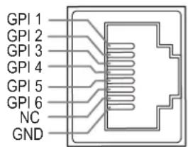
The GPI control allows you to control both the Tally light and the on screen TALLY light on at the same time:
\*2 UMD
Select the display type as “ “TSL3.1or 4.0” , which can be controlled with TSL UMD.
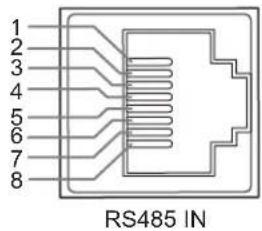
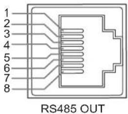
| Pin No | RS 485 IN | RS 485 OUT |
| 1 | GND | GND |
| 2 | NC | NC |
| 3 | RXD- | RXD- |
| 4 | NC | NC |
| 5 | NC | NC |
| 6 | RXD+ | RXD+ |
| 7 | TXD- | TXD- |
| 8 | TXD+ | TXD+ |
Cascade:
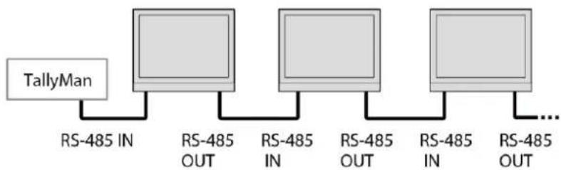
flowchart
graph LR
    A["TallyMan"] --> B["RS-485 IN"]
    B --> C["RS-485 OUT"]
    C --> D["RS-485 IN"]
    D --> E["RS-485 OUT"]
    E --> F["RS-485 IN"]
    F --> G["RS-485 OUT"]
    G --> H["..."]
\*3 RS485 address
When Multi-screen-"4-screen or 2-screen" is selected, if screen 1/2/3/4 or screen 1/2 are set to different addresses, the UMD of a single screen can be controlled separately
- Assist-Setting for Vector scope and Histogram patterns.
| Menu Item | Menu Description | Value | |
| False Color | Turn false color display on or off | OFF, ON | |
| Blue Only | Turn blue only on or off | OFF, ON | |
| Focus Assist | Turn on or off focus assist and adjust the color of the focus assist | OFF, Blue, Red | |
| Zebra | Turn zebra on or off | OFF, ON | |
| Waveform | Waveform | Turn waveform on or off | OFF, ON |
| WFM Type | Set the WFM Type | Y, Cb, Cr, R,G,B,RGB | |
| WFM Position | Set the WFM position | Bottom Left, Bottom Right, Top Left, Top Right | |
| WFM Blending | Set the blending of the background color of the waveform | OFF, High, Low | |
| WFM Brigh | Set the brightness within a WFM image | Low, Medium, High | |
| WFM Color | Set the color of the waveform displayed on the waveform chart | White, Green, Color | |
| WFM Single Line^1 | Switch on single line waveform | OFF, ON | |
| WFM Line Count | Set a line for the single line waveform | 1-1080 | |
| Vector | Vector | Turn vector on or off | OFF, ON |
| Vector Position | Adjust the position of the vector on the screen | Bottom Left, Bottom Right, Top Left, Top Right | |
| Vector Blending | Vector scope transparency selection | OFF, LOW, HIGH | |
| Vector Brigh | Set the brightness within a vector image | Low, Medium, High | |
| Vector Color | Set vector colors | White, Green, Color | |
| CIE | CIE | Turn the colour gamut chart on or off | On,Off |
| CIE Position | Adjusting the position of the colour gamut map on the screen | Top left, Top right, Bottom left, Bottom right | |
| CIE Blending | Set the transparency of the background colour of the colour gamut map | Off, Low, High | |
| CIE Bright | Set the brightness within the colour gamut map chart | Low, Medium, High | |
| CIE Color | Set gamut map colours | White, green, colour | |
| Histogram | Histogram | Turn histogram on or off | OFF, ON |
| Histogram Position | Set the display position on the histogram screen | Top left, Top right, Bottom left, Bottom right | |
| Histogram Blending | Set the transparency of histogram background color | OFF, LOW, HIGH | |
| Marker | Marker | Turn marker on or off | OFF, ON |
| Marker Select | Set the scale of the market line | 16:9,15:9,14:9,13:9,4:3,2.35:1,2:1, 1.85:1,2.39: 1, USER1, USER2 | |
| Horizontal(user 1)^2 | Set the X - axis value of the marker | 50%~99% | |
| Vertical(user 1) | Set the Y - axis value of the marker | 50%~99% | |
| Horizontal(user 2)^3 | Set the X - axis value of the marker | 0~1920 | |
| Vertical(user 2) | Set the Y - axis value of the marker | 0~1080 | |
| Safety area | Set safety area percentage | 80%~100% | |
| Fit Marker | Set safety area to fit marker ratio or not | OFF, ON | |
| Center Marker | Switch on the center cross marker | OFF, ON | |
| Marker Color | Select a color for marker | White, Red, Green, Blue, Black, Gray | |
| Marker type | Set the display type of marker | Type 1, Type 2 | |
| Marker outside | Marker outside color setting | OFF, Black, Gray | |
| Eye pattern*4 | Turn eye pattern on or off ON,OFF | ||
\*1 WFM Single Line
Open waveform single-line mode, the monitor shows only one line of audio waveform. Rotate the Menu/Enter knob to select the number of lines of audio signal to display the waveform. (The selection range of the number of lines in a waveform depends on the current signal standard)
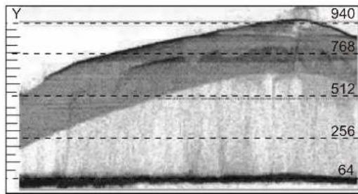
area
| Y | Value | | --- | ----- | | 64 | 940 | | 256 | 768 | | 512 | 512 | | 940 | 940 |WFM Single Line:OFF
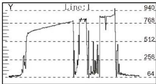
line
| Point | Value | |-------|-------| | 1 | 64 | | 2 | 256 | | 3 | 512 | | 4 | 768 | | 5 | 940 |WFM Single Line:ON
\* 2 Horizontal / Vertical (user 1)
When the value of the scale item is set to "User 1", the user can adjust the X position and Y position of the marking line according to his/her own needs, and the coordinate value can be adjusted in the range of 50%\~99%;
\*3 Horizontal / Vertical (User 2)
When the value of the scale item is set to "User 2", users can adjust the X position and Y position of the marking line according to their own needs, and the X coordinate value can be adjusted in the range of 0\~1920, and the Y coordinate value can be adjusted in the range of 0\~1080.
\*4 Eye pattern
Only SDI1 supports eye diagram to monitor the image quality of the current SDI video signal after transmission over the cable, especially the transmission quality of 12G SDI.
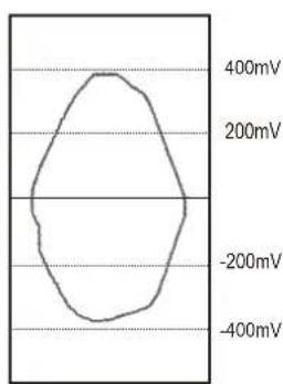
Good Signal
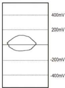
line
| Voltage (mV) | | :--- | | -200 | | -400 | | -200 | | 200 | | 400 |Bad Signal
8. De-embed— Setting for video/audio analysis functions
| Menu Item | Menu Description | Value | |
| Audio Meter | Audio Meter | Turning audio meters on or off | ON,OFF |
| Audio meter Position | Adjusting the position of the audio meter on the screen | Top Left, Top Right, Bottom Left, Bottom Right | |
| Audio meter Blending | Set the transparency of the audio meter background colour | OFF,LOW,HIGH | |
| Audio meter marker'1 | Setting the audio meter marker line | ON,OFF | |
| Lissajous | Lissajous Pattern | Turn on or off Lissajous figure | ON,OFF |
| Lissajous position | Set the position of the Lissajous position on the screen | Top Left, Top Right, Bottom Left, Bottom Right | |
| lissajour Blending | Set the Blending of the Lissajous background colour | Off, Low, High | |
| Surround Phase | Surround Phase | Turn surround Phase on or off | ON,OFF |
| Surround Position | Adjusting the position of the surround sound display on the screen | Top Left, Top Right, Bottom Left, Bottom Right | |
| Surround type | Selecting the type of surround sound | 5.1, | |
| Surround Blending | Set the transparency of the surround sound background colour | OFF,LOW,HIGH | |
| Left Channel*2 | Select the left channel output channel | Channel 1~16 | |
| Right Channel | Select the right channel output channel | Channel 1~16 | |
| Volume | Adjust audio volume | 0~100 | |
| Time code | Turn on/off Time code | OFF, ON | |
| H/V Delay*3 | Turn on/off H/V Delay | OFF, ON | |
\*1. Audio meter marker
Audio table display, display 16 channel audio table
Marking line off: Only the audio table is displayed
Marking line on: Display audio decibels, audio alarm signal and left and right channel options
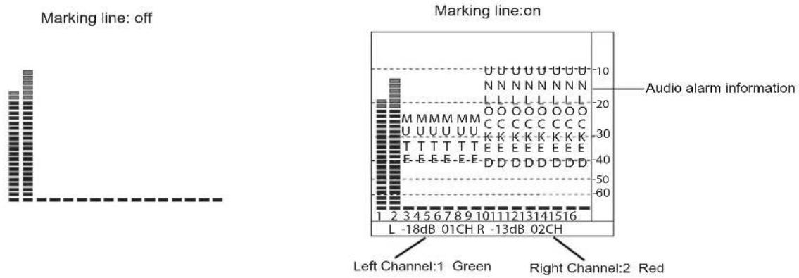
bar
| Channel | Count | | ------- | ----- | | Left Channel:1 Green | 1 | | Right Channel:2 Red | 60 |\*2. Left Channel/ Right Channel
Audio meter under SDI showing 16 channel audio meter
Audio meter under HDMI ^® , menu shows 8 groups of channels
\*3. H/V Delay
H/V Delay is not displayed on HDMI ^® channel.
9. Auto Calibration ^4
| Menu Item | Menu Description | Value |
| Probe Select ^2 | Select a probe to use | X-rite I1 Pro OEM, Jeti Specbos 1211 |
| Start Calibration ^3 | Select whether to start calibration | No/Yes |
| Measure ^4 | Test current color | No/Yes |
\*1. Auto Calibration
The monitor has built-in 3DLUT colour calibration software, which supports Atheros X-rite I1 Pro OEM and JETI Specobos1211 colour probes directly connected to the monitor via USB.
When calibration starts, the colour probe will read the standard colour graphics generated by the monitor and load the results to the monitor via the USB port.
The monitor internally compares the standard colours with the colours read by the probe to generate a 3DLUT table and complete the automatic colour calibration.
Calibration time: X-rite I1: 15 minutes, JETI Specobos1211: 45 minutes.
Calibration result Delta E <1.0.
\*2.Probe Select
This monitor supports the following probes models:
| BRAND | MODEI |
| X-rite | I1 Pro OEM (SWIT OEM) |
| JETI | Specbos 1211 |
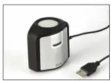
X-rite |1
(SWIT Exclusive Edition only)
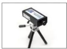
JETI Specbos 1211
\*3.Start Calibration
Steps:
- Put the monitor into a dark room. Switch on the monitor.
- Connect the calibration instrument (compatible with x-rite and JETI color measuring instruments) and monitor via USB. Before calibration, ensure that the monitor and the color calibration instrument are in good condition and the monitor aging time reaches 30 minutes.
- Enter the "Probe Select" and select the currently used calibration probe.
- Enter the “Start Calibration” and select “yes” to start calibration. The monitor will display the prompt message and the color position prompt box. Put the sensitive part of the device in the color position prompt box correctly. Note that when placing the calibration instrument; do not squeeze the monitor’s LCD screen.
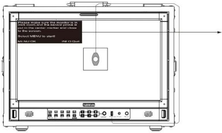
Please make sure the monitor is in dark room, and the sensor probe is put in the center marker and close to the screen.
Select MENU to start!
MENU:OK
INFO:Quit
-
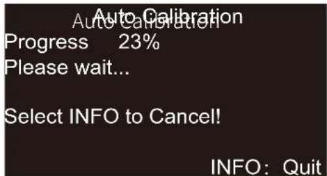
Select "yes" to begin auto calibration. The color calibration instrument will automatically measure the color of the screen and correct the color of the screen. During this process, it is necessary to observe the color calibration progress bar in the color correction prompt box.
-
Press "INFO" to terminate the color correction process at any time. When the prompt color calibration progress reaches 100%, the whole automatic color calibration is completed. After automatic color correction, press the "INFO" button to exit the menu and let the monitor enter the normal display mode.
-
After the automatic color correction, the
tion" and "After Calibration".
\*4. Measure
The monitor has been calibrated in factory. And may need to be re-calibrated after a period of time. Before re-calibrated, the measure function can check the current color to compare with the last time calibrated color, to decide if the monitor needs to be re-calibrated. Connect with the sensor probe and place the sensor probe onto the right position like calibration step. Enter “Auto Calibration” – “Measure”. The monitor will generate several colors and finish measure within 30 seconds. And display the result as:
scatter
| Gene | Before Calibration | After Calibration | |------|---------------------|---------------------| | R | 1.0 | 1.5 | | R75 | 1.0 | 1.5 | | Mg | 1.0 | 1.5 | | Mg75 | 1.0 | 1.5 | | R | 1.0 | 1.5 | | R75 | 1.0 | 1.5 | | Gy | 1.0 | 1.5 | | G75 | 1.0 | 1.5 | | G | 1.0 | 1.5 | | G3 | 1.0 | 1.5 | | Y1 | 1.0 | 1.5 | | Y15 | 1.0 | 1.5 | | Y2 | 1.0 | 1.5 | | Data = 1.0 | - | - | The chart displays two panels: “Before Calibration” and “After Calibration,” with each panel containing multiple data points (squares or circles) and labeled with gene names (e.g., R, M, G, R75, R75). The legend indicates “pu spop nees calpsid” in the top-left corner.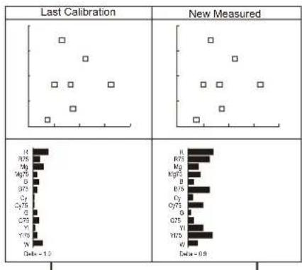
scatter
| Category | Last Calibration | New Measured | | -------- | ---------------- | ------------ | | R | 1.0 | 1.0 | | M | 1.0 | 1.0 | | M2 | 1.0 | 1.0 | | M3 | 1.0 | 1.0 | | O | 1.0 | 1.0 | | O7 | 1.0 | 1.0 | | C2 | 1.0 | 1.0 | | C3 | 1.0 | 1.0 | | O | 1.0 | 1.0 | | Q | 1.0 | 1.0 | | Q5 | 1.0 | 1.0 | | Y | 1.0 | 1.0 | | Y7 | 1.0 | 1.0 | | N | 1.0 | 1.0 | | Beta = -1.0 | 1.0 | 1.0 | | Beta = 0.9 | 1.0 | 1.0 |CIE and Delta E from last calibration
CIE and Delta E from new measured
10. System-User profile saving, firmware update.
| Menu Item | Menu Description | Value |
| Key Lock*1 | Set lock key | OFF, Full Lock |
| Recall Profile*2 | Select make user mode current | Factory,USER1,USER2,USER3,USER4 |
| Save Profile | Save the current state as a user setting | USER1,USER2,USER3,USER4 |
| Payload ID | When turned on, Payload ID information conforming to SMPTE ST 352 standard is automatically adapted | OFF, ON |
| Low Latency Mode | Open or close low latency mode | OFF, ON |
| Green mode | Set the display mode of green mode | Black Backlight, Gray Backlight |
| Idle Duration | Set how long it will be in the no-signal state and turn on green mode | 30 Sec, 1 Hour, 2 Hours, 4 Hours, OFF |
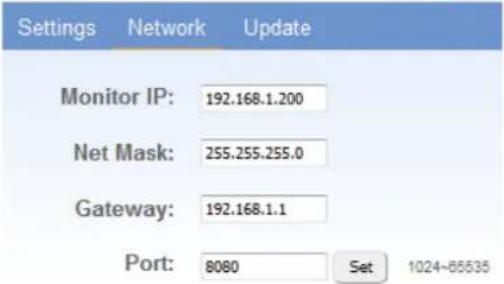
| IP*3 | Set up the monitor IP address to achieve remote web control | 192.168.001.200 |
| Net Mask | 255.255.255.000 | |
| Gateway | 192.168.001.001 | |
| Port(1024~65535) | 08080 | |
| OSD TIME | Set OSD display time | 5~180 |
| Key Brightness | Set the brightness of the key lamp | OFF, Low, High |
| Language | Select Chinese or English language to display | Chinese, English |
| System Reset | Reset all Settings in the menu system | No/Yes |
| Update *4 | Set whether to upgrade firmware | No/Yes |
\*1.Key Lock
ALL
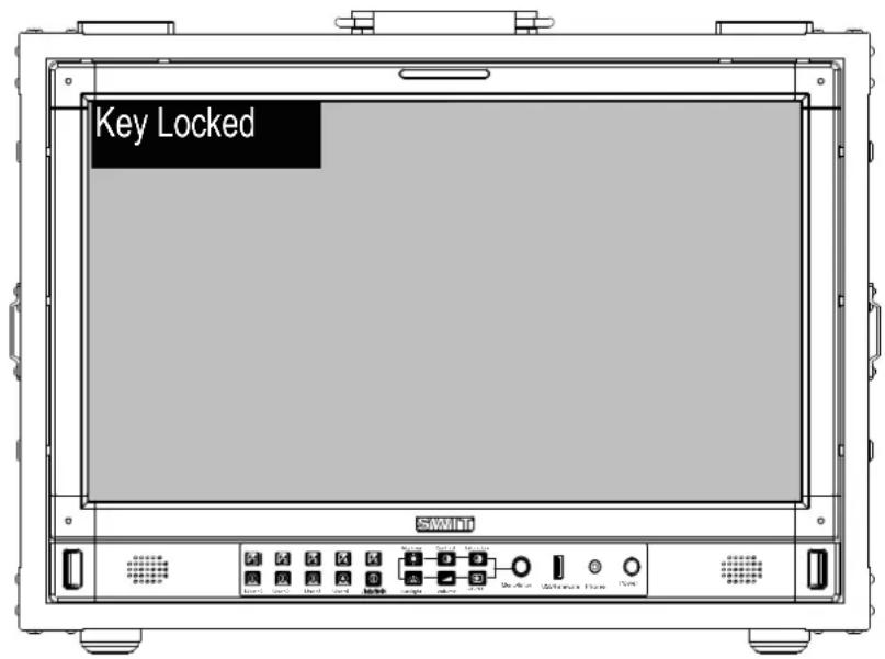
The “Menu/Enter” button can be operated when the button is locked. “Key Locked” will be displayed on the screen when you press the Locked button or knob.
\*2 Recall Profile/ Save Profile
User Settings provide 4 menu Settings, that is, users can save the current monitor menu Settings as one user Settings (USER1\~USER4) according to usage habits. Then, when switching menu Settings, just select the corresponding "USER1\~USER4" through the "Recall Profile" item to display the corresponding menu Settings. Example: By adjusting the parameters of the color temperature of 2200K, open the necessary auxiliary functions (such as: histogram), set the function key to the desired menu (such as F1 is set to "Blue Only"), and so on, the monitor Menu Settings can be "USER Settings" save as "USER" 1, rotating the "Menu/Enter" choose to load the USER Settings "set to the current" USER 1 "mode, the monitor Menu item value will show" USER 1 "mode to save Menu.
\*3 IP control
Connect the monitor to the LAN through an ETHERNET interface, and the Monitor can be controlled by web page.
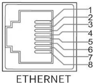
| Pin No | Pin Name |
| 1 | MD0P |
| 2 | MD0N |
| 3 | MD1P |
| 4 | MD1N |
| 5 | MD2P |
| 6 | MD2N |
| 7 | MD3P |
| 8 | MD3N |
Enter Menu- System – IP/Net Mask/Gateway/Port to set the monitor address. Set the computer Ethernet IP addresses at the same LAN environment as the Monitor. Launch any of a web browser on the computer, and enter URL: Monitor IP+ Port (Example: 192.168.1.99.8080). The web server control page will be displayed.
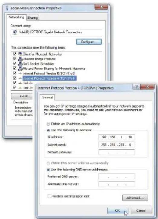
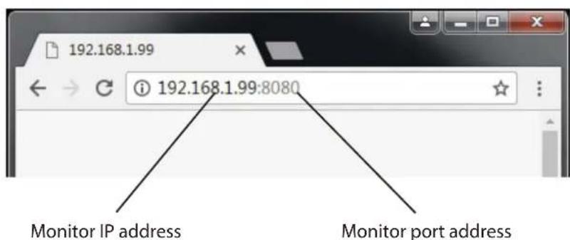
Fig1: IP Address setting Fig2: Web page
● Used crossed wired cable for computer-monitor directly connection.
- Use straight-through wired cable for Router connections.
- Please seek help from your webmaster for any network connections.
Webserver page control interface
SWIT.
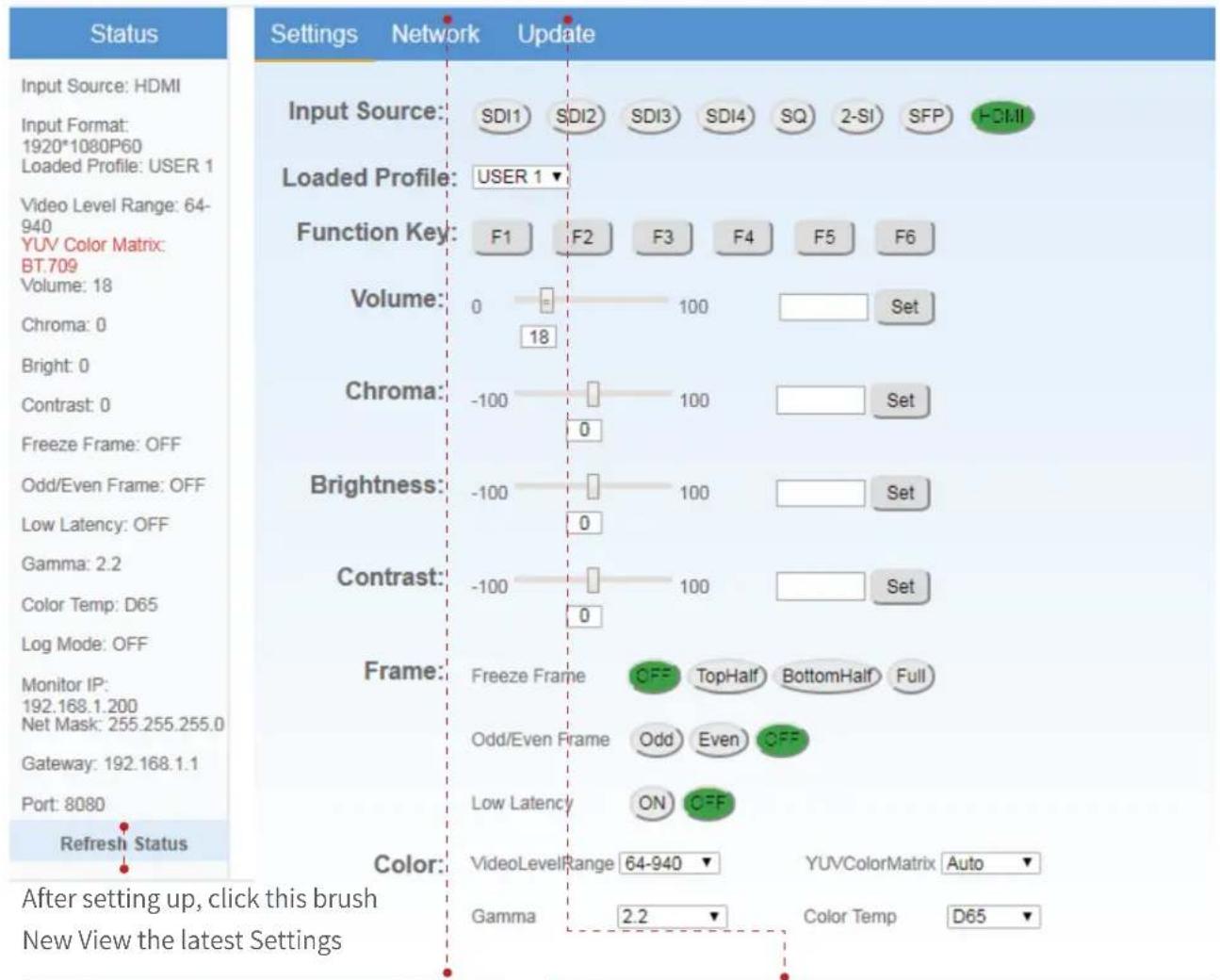
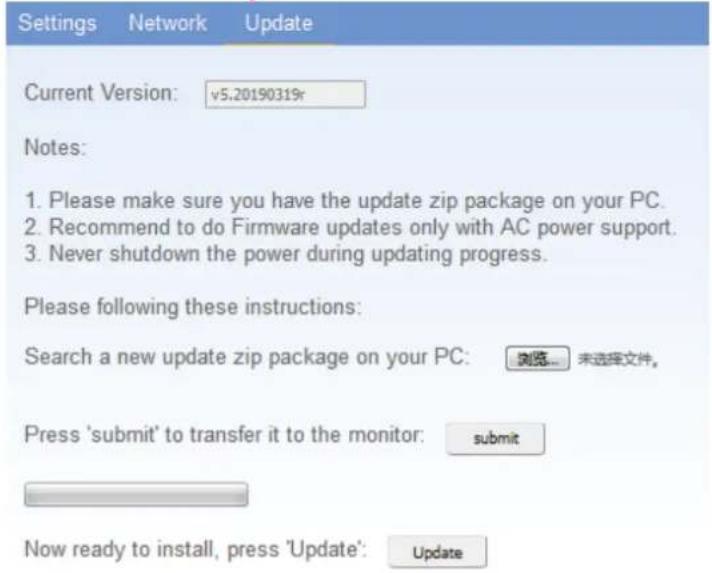
\*4.Update
System software can update by USB interface, and steps are as follows:
- Download the latest software package into the U-disk root direction.
- Open the monitor and plug U-disk into USB into port.
- Follow the step "Menu-System-Update", the monitor will update automatically.
- When update finishes, press "Power" button, close and reboot the monitor.
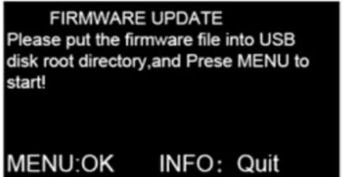
※Remark
- Only copy one model and software version into the U-disk root direction.
- Never shutdown the power during the update progress.
11. Multiview setting
| Menu item | Menu description | Value |
| Multiview type *2 | Selects the Multiview typ | Quad View、PBP、PIP |
| PIC 1 | Select channel 1 when set to PBP or PIP. | SDI 1、SDI 2、SDI 3、SDI 4、HDMI® |
| PIC 2 | Select channel 2 when set to PBP or PIP | SDI 1、SDI 2、SDI 3、SDI 4、HDMI® |
| PIP Windoe position | Select PIC2 position when set to PIP | Top left, top right, centre, bottom left, bottom right |
| Border | Switch on/off the border | On/OFF |
| Flip(PBP)*3 | Type mode selected at the PBP | Off, type 1, type 2, type 3 |
\*1 Multiview setting
Source selects Multiview before the Multiview Setup menu is adjustable and some menu functions are disabled;
When Multiview is selected, the quantisation range, colour gamut and gamma of each channel can be adjusted individually.
\*2 Multiview type
4-channel or 2-channel independent 12G/6G/3G/HD-SDI or HDMI ^® mixed 4-screen or 2-screen monitoring;
4-screen: If there is no signal input on the 4th screen, HDMI ^® signal appears on the 4th;
\*3 Flip(PBP)
Select the required type, and the screen is in vertical mode to monitor the screen.
Appearance and Size
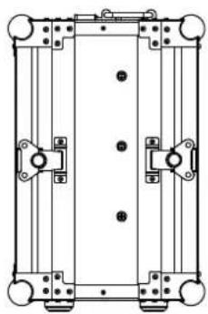
Flight Case Monitor Appearance
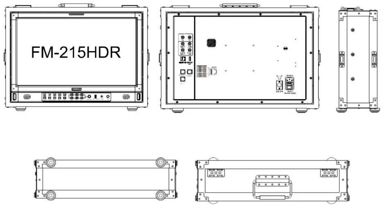
Aluminium flight case (unit: mm)
natural_image
Pure mechanical assembly diagram with no text, numbers, or symbols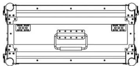
natural_image
Technical line drawing of a mechanical or electronic component with mounting holes and internal connectors (no text or symbols)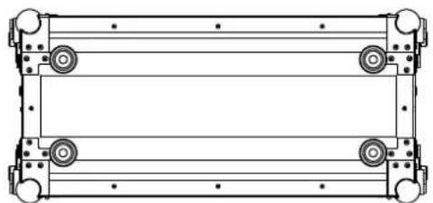
natural_image
Technical line drawing of a mechanical frame with four circular components and mounting holes (no text or symbols)| Model No. | FM-215HDR | |
| Screen Size | 21.5 inch | |
| Display Area | 476.064×267.786mm | |
| Resolution | 1920×1080 | |
| Display Colour | 16.7M | |
| Display Ratio | 16:9 | |
| Maximum Brightness | 1000 cd/m2 | |
| Contrast Ratio | 1000:1 | |
| Colour depth | 8bit | |
| Signal Processing | 18-bit | |
| Viewing angle H/V | 178°/178° | |
| Input/Output Interface | ||
| Input | BNC×4 | 12G/6G/3G/HD/SD-SDI×1, 3G/HD/SD-SDI×3 |
| HDMI®×1 | HDMI®2.0 input | |
| RS-485×1 | TSL3.1/4.0 UMD dynamic source name input | |
| RS-485×1 | GPI (Tally) input | |
| USB×1 | ||
| RJ-45×1 | Gigabit Ethernet port, IP web control access | |
| Output | BNC×2 | 12G/6G/3G/HD/SD-SDI×1, 3G/HD/SD-SDI×1 |
| RS-485×1 | TSL3.1/4.0 UMD dynamic source name output | |
| Analog audio | Analog audio 3.5mm and speaker output | |
| Other specifications | ||
| Operating Voltage AC | 100V~240V 50/60Hz | |
| DC/Battery | 11V~17V | |
| Power consumption | ≤60W | |
| Operating Temperature | 0°C~+45°C | |
| Operating humidity | 10%~90% | |
| Storage temperature | -15°C~ + 60°C | |
| Storage humidity | 10%~90% | |
| flight box size | 570×260×405mm | |
| Net weight (main unit only) | 7.28KG | |
| Net weight of flight box | 6.8KG | |
Supported standards: Signals of the following standards can be displayed on the monitor
| No. | Format | Input terminal Signal format shown in the Status Display as | ||||||
| SDI1 | SDI 2/3/4 | Quadlink SDI | HDMI® | SDI1 out | SDI2 out | HDMI® | ||
| 1 | 1280×720/50P | √ | √ | — | √ | 1280*720P50 | 1280*720P50 | 1280*720P50 |
| 2 | 1280×720/59.94P | √ | √ | — | √ | 1280*720P59.94 | 1280*720P59.94 | 1280*720P60 |
| 3 | 1280×720/60P | √ | √ | — | √ | 1280*720P60 | 1280*720P60 | 1280*720P60 |
| 4 | 1920×1080/50I | √ | √ | — | √ | 1920*1080I50 | 1920*1080I50 | 1920*1080I50 |
| 5 | 1920×1080/59.94I | √ | √ | — | √ | 1920*1080I59.94 | 1920*1080I59.94 | 1920*1080I60 |
| 6 | 1920×1080/60I | √ | √ | — | √ | 1920*1080I60 | 1920*1080I60 | 1920*1080I60 |
| 7 | 1920×1080/23.98PSF | √ | √ | — | √ | 1920*1080PSF23.98 | 1920*1080PSF23.98 | 1920*1080PSF24 |
| 8 | 1920×1080/24PSF | √ | √ | — | √ | 1920*1080PSF24 | 1920*1080PSF24 | 1920*1080PSF24 |
| 9 | 1920×1080/23.98P | √ | √ | — | √ | 1920*1080P23.98 | 1920*1080P23.98 | 1920*1080P24 |
| 10 | 1920×1080/24P | √ | √ | — | √ | 1920*1080P24 | 1920*1080P24 | 1920*1080P24 |
| 11 | 1920×1080/25P | √ | √ | — | √ | 1920*1080P25 | 1920*1080P25 | 1920*1080P25 |
| 12 | 1920×1080/29.97P | √ | √ | — | √ | 1920*1080P29.97 | 1920*1080P29.97 | 1920*1080P30 |
| 13 | 1920×1080/30P | √ | √ | — | √ | 1920*1080P30 | 1920*1080P30 | 1920*1080P30 |
| 14 | 1920×1080/48P | √ | √ | — | √ | 1920*1080P48 | 1920*1080P48 | 1920*1080P48 |
| 15 | 1920×1080/50P | √ | √ | — | √ | 1920*1080P50 | 1920*1080P50 | 1920*1080P50 |
| 16 | 1920×1080/59.94P | √ | √ | — | √ | 1920*1080P59.94 | 1920*1080P59.94 | 1920*1080P60 |
| 17 | 1920×1080/60P | √ | √ | — | √ | 1920*1080P60 | 1920*1080P60 | 1920*1080P60 |
| 18 | 2048×1080/23.98PSF | √ | — | — | √ | 2048*1080PSF23.98 | — | 2048*1080PSF24 |
| 19 | 2048×1080/24PSF | √ | — | — | √ | 2048*1080PSF24 | — | 2048*1080PSF24 |
| 20 | 2048×1080/25PSF | √ | — | — | √ | 2048*1080PSF25 | — | 2048*1080PSF25 |
| 21 | 2048×1080/29.97PSF | √ | — | — | √ | 2048*1080PSF29.97 | — | 2048*1080PSF30 |
| 22 | 2048×1080/30PSF | √ | — | — | √ | 2048*1080PSF30 | — | 2048*1080PSF30 |
| 23 | 2048×1080/23.98P | √ | — | — | √ | 2048*1080P23.98 | — | 2048*1080P24 |
| 24 | 2048×1080/24P | √ | — | — | √ | 2048*1080P24 | — | 2048*1080P24 |
| 25 | 2048×1080/25P | √ | — | — | √ | 2048*1080P25 | — | 2048*1080P25 |
| 26 | 2048×1080/29.97P | √ | — | — | √ | 2048*1080P29.97 | — | 2048*1080P30 |
| 27 | 2048×1080/30P | √ | — | — | √ | 2048*1080P30 | — | 2048*1080P30 |
| 28 | 2048×1080/47.94P | √ | — | — | √ | 2048*1080P47.94 | — | 2048*1080P50 |
| 29 | 2048×1080/48P | √ | — | — | √ | 2048*1080P48 | — | 2048*1080P48 |
| 30 | 2048×1080/50P | √ | — | — | √ | 2048*1080P50 | — | 2048*1080P50 |
| 31 | 2048×1080/59.94P | √ | — | — | √ | 2048*1080P59.94 | — | 2048*1080P60 |
| 32 | 2048×1080/60P | √ | — | — | √ | 2048*1080P60 | — | 2048*1080P60 |
| 33 | 3840×2160/23.98P | √ | — | √ | √ | 3840*2160P23.98 | — | 3840*2160P24 |
| 34 | 3840×2160/24P | √ | — | √ | √ | 3840*2160P24 | — | 3840*2160P24 |
| 35 | 3840×2160/25P | √ | — | √ | √ | 3840*2160p25 | — | 3840*2160p25 |
| 36 | 3840×2160/29.97P | √ | — | √ | √ | 3840*2160P29.97 | — | 3840*2160P30 |
| 37 | 3840×2160/30P | √ | — | √ | √ | 3840*2160P30 | — | 3840*2160P30 |
| 38 | 3840×2160/47.94P | √ | — | √ | √ | 3840*2160P47.94 | — | 3840*2160P50 |
| 39 | 3840×2160/48P | √ | — | √ | √ | 3840*2160P48 | — | 3840*2160P48 |
| 40 | 3840×2160/50P | √ | — | √ | √ | 3840*2160P50 | — | 3840*2160P50 |
| 41 | 3840×2160/59.94P | √ | — | √ | √ | 3840*2160P59.94 | — | 3840*2160P60 |
| 42 | 3840×2160/60P | √ | — | √ | √ | 3840*2160P60 | — | 3840*2160P60 |
| 43 | 4096×2160/23.98P | √ | — | √ | √ | 4096*2160P23.98 | — | 4096*2160P24 |
| 44 | 4096×2160/24P | √ | — | √ | √ | 4096*2160P24 | — | 4096*2160P24 |
| 45 | 4096×2160/25P | √ | — | √ | √ | 4096*2160P25 | — | 4096*2160P25 |
| 46 | 4096×2160/29.97P | √ | — | √ | √ | 4096*2160P29.97 | — | 4096*2160P30 |
| 47 | 4096×2160/30P | √ | — | √ | √ | 4096*2160P30 | — | 4096*2160P30 |
| 48 | 4096×2160/47.94P | √ | — | √ | √ | 4096*2160P47.94 | — | 4096*2160P48 |
| 49 | 4096×2160/48P | √ | — | √ | √ | 4096*2160P48 | — | 4096*2160P48 |
| 50 | 4096×2160/50P | √ | — | √ | √ | 4096*2160P50 | — | 4096*2160P50 |
| 51 | 4096×2160/59.94P | √ | — | √ | √ | 4096*2160P59.94 | — | 4096*2160P60 |
| 52 | 4096×2160/60P | √ | — | √ | √ | 4096*2160P60 | — | 4096*2160P60 |
3G supports level A/levelB; Support RGB444
√: The format is supported
—: The format is not supported
Common Problems and Solutions
| symptom | Possible causes Solution | |
| No display | The power is not turned on | Please check if the power is connected, and then press “POWER” button to turn on the monitor |
| Unstable power voltage | Reconnect to power supply | |
| BNC or HDMI® cable loose contact or not correctly connected | Check and correctly connect the BNC or HDMI® cable | |
| The attached battery is no power | Change battery | |
| Using DIY power supply but the polarity is reversed | Refer to the provided power supply, reconnect the power. | |
| Image or color abnormal | Bad contact of BNC or HDMI® cable | Change the Video cable |
| Video signal has Interference | Remove the interference source(s) | |
| Improper adjustment of the color parameters | Adjust the “Recall profile” to “Default” under “System” submenu | |
| Distortion of the image | Reset the Aspect ratio | |
| Set to Blue only | Turn off the “pure color” setting | |
| Turn on the “Focus Assist” function | Turn off the “Focus Assist” function | |
| Turn on the “False Color” function | Turn off the “False Color” function | |
| No audio output | Set mute state | Cancel mute state or spin “MENU/ENTER” to adjust volume |
| Bad contact of signal cable | Change signal cable | |
| Wrong connection or bad contact of Audio cable | Connect to the correct input socket |
SWIT®
SWIT Electronics Co., Ltd.
Add: 10 Hengtong Road, Xin'gang, Nanjing Economic and
Technological Development Zone, Nanjing 210038, P.R.China
Tel: +86-25-85805753 Email: contact@swit.cc

- User Manual
- Declaration
- SWIT Electronics Co., Ltd.
- Maintaince percautions
- Warning
- Precautions for power supply
- Precautions for product use
- Precautions for product cleaning
- Content
- Introduction
- Features:
- Front panel
- OSD
- TALLY Light
- Time Code(SDI)
- On screen TALLY
- Source ID/UMD
- Colour gamut char
- Histogram
- Waveform
- Vectors
- Lissajous
- Audio Meter
- Surround Phase
- Eye pattern
- Colour checklist
- Button operation
- Note
- Input—Set the color of input video
- Image setting 1 —Setting for the picture preference
- \*1 Image Settings
- \*1 Color gamut
- \*2 Gamma
- \*3 HLG System Gamma
- \*4 Partition HDR/SDR
- \*5 LUT Upload
- Scanning—Setting for picture scan, zoom, etc.
- \*1. Scanning
- \*2. Zoom -in: Shown below, the image is divided into 9 regions and adjusted to display in sequence.
- \*3.Odd/Even Frame
- \*1 GPI control
- \*2 UMD
- Cascade:
- \*3 RS485 address
- \*1 WFM Single Line
- \* 2 Horizontal / Vertical (user 1)
- \*3 Horizontal / Vertical (User 2)
- \*4 Eye pattern
- De-embed— Setting for video/audio analysis functions
- \*1. Audio meter marker
- \*2. Left Channel/ Right Channel
- \*3. H/V Delay
- Auto Calibration 4
- \*1. Auto Calibration
- \*2.Probe Select
- \*3.Start Calibration
- Steps:
- \*4. Measure
- System-User profile saving, firmware update.
- \*1.Key Lock
- \*2 Recall Profile/ Save Profile
- \*3 IP control
- Webserver page control interface
- \*4.Update
- Multiview setting
- \*1 Multiview setting
- \*2 Multiview type
- \*3 Flip(PBP)
- Appearance and Size
- SWIT®
Brand : SWIT
Model : FM-215HDR
Category : Monitor