
CM-S73H - Monitor SWIT - Free user manual and instructions
Find the device manual for free CM-S73H SWIT in PDF.


| Product Type | 7-inch professional on-camera monitor |
| Brand | SWIT |
| Model | CM-S73H |
| Display Size | 7 inch (151.2 × 94.5 mm) |
| Resolution | 1920 × RGB × 1200 |
| Brightness | 3000 cd/m² (max, with ≥12V power supply) |
| Contrast Ratio | 1200:1 |
| Viewing Angle | 160° horizontal / 160° vertical |
| Color Depth | 8 bit |
| Aspect Ratio | 16:9 / 4:3 (switchable) |
| Video Inputs | 1× HDMI (HDMI 2.0, supports 4K), 2× 3G-SDI (BNC), 1× USB (firmware upgrade) |
| Video Outputs | 1× HDMI (loop out), 1× 3G-SDI (loop out, fixed to SDI-IN1), 1× 3.5mm headphone (embedded audio) |
| Power Input | DC 6.5–17 V (round plug, center positive), compatible with battery mount (V-mount/Gold mount) |
| Power Consumption | ≤26 W |
| Weight (main body) | 500 g |
| Dimensions (W×H×D) | 187 × 137 × 41 mm |
| Working Temperature | -10°C to +50°C |
| Storage Temperature | -15°C to +60°C |
| Supported Video Formats (HDMI) | 480i/576i/480p/576p, 1080i (60/59.94/50), 720p (60/59.94/50), 1080p (up to 60), 1080psf, 4096×2160 up to 60p, 3840×2160 up to 60p |
| Supported Video Formats (SDI) | SMPTE-425M A/B, 1080p 60/59.94/50, 1080i 60/59.94/50, 1080p 30/29.97/25/24/23.98, 1080psf, 720p 60/59.94/50, 480i (59.94), 576i (50), 2048×1080 up to 60p |
| Special Features | Camera Log conversion (J-Log1, Log-C, S-Log2, C-Log, V-Log, RedlogFilm, User-Log), HDR (PQ_709, HLG_709, S-Log3), 3D LUT cube import, Focus assist (red/blue), Zebra stripes, False color, Waveform, Vector, Histogram, 16-ch embedded audio meters, Time code, UMD, Tally (soft and GPI), Key inhibit, USB firmware upgrade, Backlight level (Off/Low/Medium/High) |
| Maintenance | Clean screen with dry soft cloth or special LCD cleaner; do not use water or chemical cleansers; avoid touching or pressing the screen |
| Warranty | 2 years (does not cover scratches, dead pixels, damage from third-party adapters, misuse, or unauthorized disassembly) |
Frequently Asked Questions - CM-S73H SWIT
User questions about CM-S73H SWIT
0 question about this device. Answer the ones you know or ask your own.
Ask a new question about this device
Download the instructions for your Monitor in PDF format for free! Find your manual CM-S73H - SWIT and take your electronic device back in hand. On this page are published all the documents necessary for the use of your device. CM-S73H by SWIT.
USER MANUAL CM-S73H SWIT
natural_image
Line drawing of a device front panel with buttons and a central screen (no text or symbols)User Manual
Please read this user manual throughout before using
Ver: A
Preface
All internal technologies of this product are protected, including device, software and trademark. Reproduction in whole or in part without written permission is prohibited.
All brands and trademarks of SWIT Electronics Co., Ltd. are protected and other relative trademarks in this user manual are the property of their respective owners.
Due to constant effort of product development, SWIT reserves the right to make changes and improvements to the product described in this manual without prior notice.
The warranty period of this product is 2 years, and does not cover the following:
(1) Physical damage to the surface of the products, including scratches, cracks or other damage to the LCD screen or other externally exposed parts;
(2) There are no continuous bright or dark spots on the LCD panel;
(3) Any damage caused by using third-party power adaptors;
(4) Any damage or breakdown caused by use, maintenance or storage not according to the user manual.
(5) The product is disassembled by anyone other than an authorized service center.
(6) Any damage or breakdown not caused by the product design, workmanship, or manufacturing quality, etc.
* Any sales personnel have no rights to provide additional warranty.
For any suggestions and requirements on this product, please contact us through phone, fax, Email, etc.
SWIT Electronics Co., Ltd.
Address: 10 Hengtong Road, Nanjing Economic and Technological Development Zone, Nanjing 210038, P.R.China
Phone: +86-25-85805753
Fax: +86-25-85805296
Email: contact@swit.cc
http://www.swit.cc
Maintenance
Warning
- In order to reduce the risk of fire and electrical shock, do not lay this product in rain or damp places.
- Please keep away from the strong magnetic field; it may cause the noise of the video and audio signals.
The power
- Please use the power adapter provided or recommended by the manufacturer in order to avoid damage.
- For a third party power adapter, please make sure the voltage range, supplied power, and polarity of power lead are fit.
- Please disconnect the power cable under the following situations:
(A). If you do not operate this monitor for a period of time;
(B). If the power cable or power adaptor is damaged;
(C). If the monitor housing is broken.
The monitor
- Please don't touch the screen with your fingers, which would probably deface the screen.
- Please don't press the screen; the LCD is extremely exquisite and flimsy.
- Please don't lay this product on unstable place.
Cleaning
- Please clean the screen with dry and downy cloth or special LCD cleanser.
- Please do not press hard when cleaning the screen.
- Please do not use water or other chemical cleanser to clean the screen.
The chemical may damage the LCD.
Contents
Preface 2
Maintenance 2
Contents 3
Packing list 4
Introduction 4
Operation Instruction 5
Screen display 6
Zoom-in and mapping 7
Main Menu 9
Specification 17
Trouble shooting 18
Packing list
CM-S73H offers the standard package and luxury package for option.
| No. | Standard package | Luxury package | |
| 1 | Monitor | ×1 | ×1 |
| 2 | User manual | ×1 | ×1 |
| 3 | Warranty card | ×1 | ×1 |
| 4 | Cold shoe / Screw ball head | ×1 | / |
| 5 | D-tap to lockable DC cable | ×1 | ×1 |
| 6 | S-7006 (U/F/D/C) /S-7006(A/S) | ×1 | ×1 |
| 7 | Articulating arm trestle | / | ×1 |
| 8 | AC-DC power adaptor | / | ×1 |
| 9 | Power cable | / | ×1 |
| 10 | LCD protective film | / | ×1 |
| 11 | BNC SDI cable | / | ×1 |
| 12 | HDMI cable | / | ×1 |
| 13 | Carrying case | / | ×1 |
Introduction
CM-S73H adopts TFT LCD panel, with resolution 1920×1200 and wide viewing angle H160°/V120°. It supports 2 x 3GSDI (Level A/B), 1 x HDMI2.0 (4K display) input. It also supports 1x 3GSDI, 1 x HDMI and 1 x analog audio loop through output.
Features:
• 3000nit super high brightness
• Support HDMI 4K display
- Camera Log conversion
• Support 3DLut cube
- Support multiple Aspect Ratio and scan modes
- Support multiple Marker selection (Marker, Safety Area)
● Powerful audio and video analysis functions
- Support multiple functions user-defined (Source ID, function keys)
- Multiple power supply methods to meet different requirements
- USB firmware upgrade
Operation Instruction
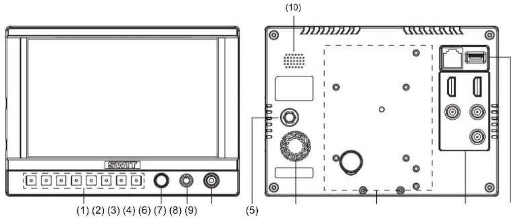
User can set F1~F3 keys to corresponding function for quick operation according to their needs.
For example: User can set F1 to “Focus Assistant”, and press F1 to directly switch the focus assistant parameter, the sequence is “Red→Blue→Off”.
Quick function keys support multi definition, for details please refer to “4.Function key settings” in the “MENU” section.
BACKLIGHT: Quickly adjust the brightness level. There are four levels of “Off”, “Low”, “Medium” and “High” optional. The corresponding brightness of “Low”, “Medium” and “High” are 380nit, 900 n and 3000 nit.
Note: When set to “Off”, the user can adjust the “Backlight” parameter value under “Picture” submenu according to the requirements.
DISPLAY: Press “DISPLAY” to turn on or turn off relevant status information, audio and video analysis assistant Pattern.
When main menu is activated, press "DISPLAY" to quit menu.
(2) Main menu settings
When no menu is opened, user can directly press the knob, and open the main menu on the left top of the screen;
Rotate the knob, select corresponding submenu; the corresponding item is highlighted in yellow; Press the knob, enter the submenu;
Rotate the knob to select items; the corresponding item is highlighted in yellow;
Press the knob, the parameter of the item is highlighted in yellow;
Rotate the knob to select the parameter and press to save the settings.
(3) POWER: Power on/off
(4) PHONE: 3.5mm earphone socket, for SDI/HDMI embedded audio and analog audio monitoring.
(5) DC 6.5-17V IN: Round head DC power supply interface (Outer: Negative, Inner: Positive)
(6) Silent fan
(7) Battery mount connector
It is powered by DV batteries. When the power supply voltage is 7.2V, the maximum brightness can reach to 2000 nit.
(8) Video Signal Interface
HDMI-IN: HDMI input (HDMI-A connector)
HDMI-OUT: HDMI output (HDMI-A connector)
SDI-IN1: 3G/HD/SD SDI input (BNC connector)
SDI-IN2: 3G/HD/SD SDI input (BNC connector)
SDI-OUT: 3G/HD/SD SDI output (BNC connector), the monitor choose fixed SDI-IN1 signal to loop output.
(9) External interface control
GPI: GPI control socket
USB: For firmware upgrade
(10) Speaker
Monitor HDMI, SDI embedded audio and analog audio monitoring. (when connecting 3.5mm audio output, the speaker is off).
Screen display
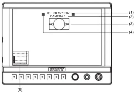
(1) Time code (SDI)
Under SDI input, it can display Time code. If no Time code information is detected, it will be displayed as "TC: UNLOCKED".
User can set function keys F1\~F3 as “Time code” to turn on or off this function
(2)、UMD
Display the source title. Set up the UMD under “UMD” submenu.
(3)、AFD (SDI)
User can set function keys F1~F3 as “AFD” to turn on or off this function. If no relevant information is detected, it will be displayed as “AFD: UNLOCKED”.
(4)、Soft Tally
When connected with TALLY control devices and set TALLY port in GPI, the screen will display soft TALLY signal, flashing in Red, Green or Yellow. Refer to “Main Menu—5. GPI”.
(5)、Audio
Monitor the audio information. User can set function Keys F1~F3 as “Audio” to turn on or off this function
The relevant parameters like position, audio channels and blending, etc can be changed under “Audio” submenu.
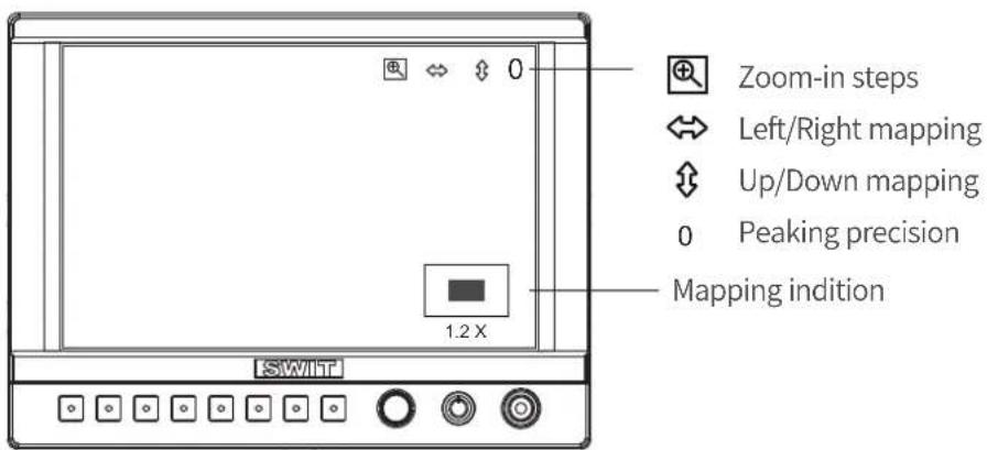
Set “Zoom-in” to function keys, and enable zoom-in mode, the OSD displays as above.
1、Zoom-in steps operation
Scroll the menu key up and down you can quickly zoom in the video by the following rates: 1.2x, 1.5x, 1.8x, 2.0x, 2.4x, 2.6x, 2.8x, 3.0x, without black waiting. The zoom-in indication window is displayed on bottom right of the screen.
Press the menu key to switch to Left/Right mapping function, and press again to switch to Up/Down mapping, and so on.
2、Left and Right mapping
Press Menu key, the button is highlighted. Scroll the Menu key up and down to move the video left and right.
3、Up and Down mapping
Press Menu key again, the button is highlighted. Scroll the Menu key up and down to move the video up and down.
4、Peaking precision adjust
Press Menu key again, the peaking precision number is highlighted. Scroll the Menu key up and down to adjust the peaking focus assist precision from 0-9.
5、Mapping indication window
Under zoom-in mode, the mapping indication window is displayed on bottom right of the screen, and indicates the zoom-in rate, up/down/left/right position.
Introduction of audio and video functions
• 16-ch embedded audio meters
Under 3G/HD/SD SDI, it displays 16 channels embedded audio meters. Under HDMI, it displays 2 channels embedded audio meters. The audio meter is green, and will turn yellow when audio exceeds -20dB, and turn red when audio exceeds -9dB.
- Audio alarm
If the embedded audio value is too low or no embedded audio, it will display “MUTE” or “UNLOCKED” in the audio bar.
• Time code (SDI)
Under SDI input, it can display the SMPTE time code (VITC1, VITC2 or LTC) on the top of the screen, which is used extensively for synchronization, and for logging and identifying material in recorded media. If no Time code information is detected, it will be displayed as “UNLOCKED”.
- Internal Color Bar
Under SDI and HDMI input, it has 100% internal color bar which helps to analyze the monitor color and adjust the display parameter.
User can set function Keys F1~F3 or GPI pins as “color bar” to turn on or off this function.
- Peaking focus assist (red/blue switch)
The Peaking focus assist function is to mark the sharpest edges of the image with red or blue color under SDI and HDMI input, for users to check if the subjects are focused.
User can set function Keys F1~F3 or GPI pins as “Focus Assist” to turn on or off this function.
- Zebra stripes
Zebra Stripes are used to check if the image is over exposed or not by showing black and white lines on the monitor. It is considered over exposed when luminance value exceeds 90%.
User can set function Keys F1\~F3 or GPI pins as “Zebra” to turn on or off this function.
- Freeze Frame
The freeze frame is to capture and display the current broadcast frame.
User can set function Keys F1~F3 or GPI pins as “Freeze Frame” to turn on or off this function
R/G/B/Mono
R/G/B/Mono is to display only the blue/red/green primary signal or the luminance signal only so as to monitor the image noise.
User can set function Keys F1~F3 or GPI pins as “R/G/B/Mono” to turn on or off this function.
False Color
The false color is used to aid in the setting of camera exposure. Under false color mode, there’s a color chart on the bottom of screen for reference. The color from the dark to the bright will be displayed as blue, cyan, green, yellow, orange and red in a consecutive way. User can set function Keys F1~F3 or GPI pins as “False color” to turn on or off this function.
- AFD (SDI)
It is the abbreviation of active format description. AFD is to display the SDI embedded AFD information graphically on the screen.
H/V Delay (SDI)
Under SDI input, H/V Delay can be used to display line/field blanking signal, and to observe the horizontal and vertical synchronous signal.
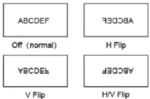
- Image flip
Horizontal, vertical, horizontal and vertical two-way image flip function.
Main menu
CM-S73H has OSD to adjust the parameters and settings, for example: Picture, color temp., function keys, etc.
- Press “MENU” button, the main menu will popup from the left top of the screen. The selected main menu highlights in yellow.
- Revolve “MENU” to select submenu, the selected submenu highlights in yellow, press “MENU” to apply and enter into the selected submenu’s items.
- Revolve “MENU” to select the item which needed to adjust, press “MENU”, the selected item and its parameters will be highlighted in yellow.
| Main Menu | Marker | ||
| Exit&Status | > | Exit | |
| Picture | > | Marker | XX |
| Color Temp | > | Marker Select | 15:9 |
| Function Key | > | Safety Area | XXX |
| GPI | > | Fit Marker | XXX |
| UMD | > | Center Marker | XXX |
| Marker | > | Marker Color | XXX |
| Marker Outside | XXX | ||
| Audio | > | ||
| Vector | > | ||
| Waveform | > | ||
| Display | > | ||
| System | > | ||
| OSD | > | ||
| Key Inhibit | > | ||
- Revolve “MENU” to change the selected item’s parameter, press “MENU” to apply and save the settings.
- Revolve “MENU” to select “Exit”, press “MENU” to quit submenu. Select “Exit & Status” under the Main Menu and press to quit Main Menu.
Notice:
* The items in gray can not be set up.
* If there is no operation under the set time, the menu will automatically save settings and quit.
* If the key inhabit function is turned on, except key inhibit function, all other items are in grey. Please turn off the key inhibit function to adjust the items.
1. Exit & Status
Displays the current status, the details are as down below:
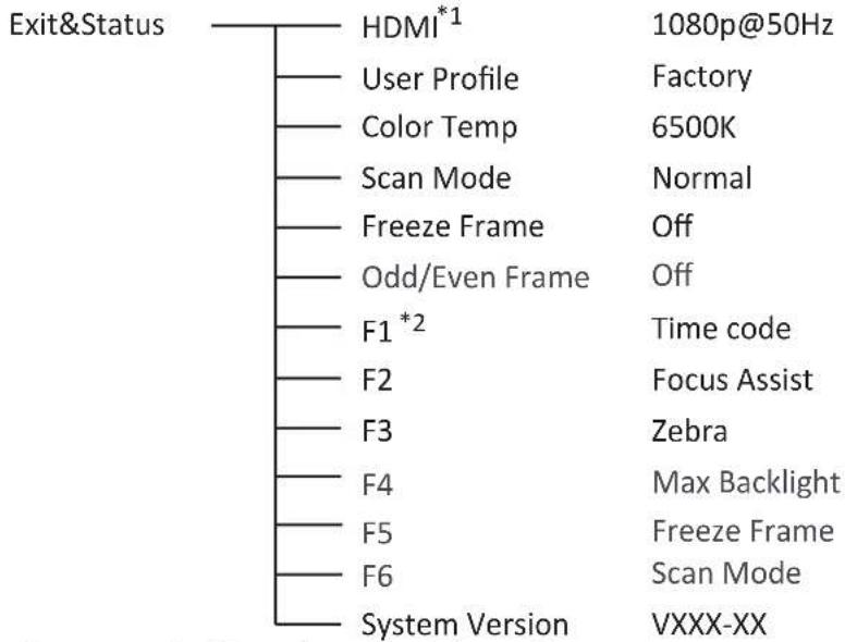
*1 Display the current video signal and format
*2 Display the current function keys setup
2. Picture
To adjust picture parameters

3. Color Temp
To select different color temperature or setup user-defined color parameters.
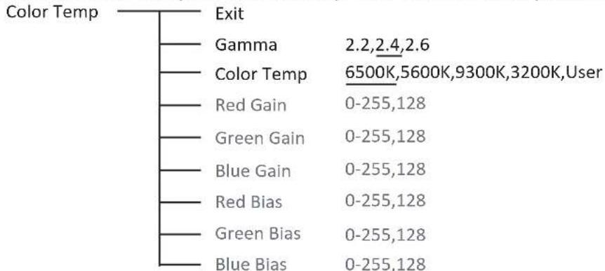
tree
| Color Temp | Exit | Gamma | 2.2,2.4,2.6 | |---|---|---|---| | | | | 6500K,5600K,9300K,3200K,User | | | | Red Gain | 0-255,128 | | | | Green Gain | 0-255,128 | | | | Blue Gain | 0-255,128 | | | | Red Bias | 0-255,128 | | | | Green Bias | 0-255,128 | | | | Blue Bias | 0-255,128 |4、Function key
To define the F1~F3 function keys
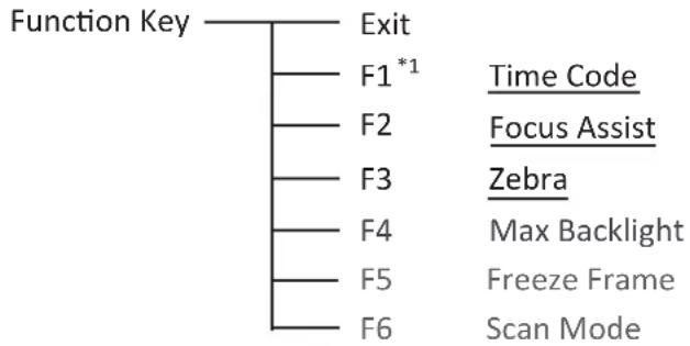
flowchart
graph TD
    A["Function Key"] --> B["Exit"]
    B --> C["F1*1"]
    C --> D["Time Code"]
    C --> E["F2"]
    E --> F["Focus Assist"]
    C --> G["F3"]
    G --> H["Zebra"]
    C --> I["F4"]
    I --> J["Max Backlight"]
    C --> K["F5"]
    K --> L["Freeze Frame"]
    C --> M["F6"]
    M --> N["Scan Mode"]
*1 Function keys F1-F3 can be set as the down below functions:
Time code, Zebra, Audio Bar, False Color, AFD, H/V Delay, R/G/B/Mono, Marker, Color Bar, UMD, Audio Alarm, Focus Assist, Aspect Ratio, Scan Mode, Zoom Mode, Mute, Freeze Frame, Flip Mode, Color Temp. For example: Set F3 to “R/G/B/Mono” under “Function key” submenu. User can press F3 on the front panel to adjust the parameters of “R/G/B/Mono”, and the “R/G/B/Mono” will change and follow the sequence: Blue Only →Red Only →Green Only →Mono →Off.
5、GPI
User can set GPI pins 1-4 to relevant functions to turn on or off this function.
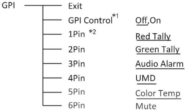
flowchart
graph TD
    A["GPI"] --> B["Exit"]
    A --> C["GPI Control*1"]
    C --> D["1Pin *2"]
    D --> E["2Pin"]
    E --> F["3Pin"]
    F --> G["4Pin"]
    G --> H["5Pin"]
    H --> I["6Pin"]
    C --> J["Off, On"]
    D --> K["Red Tally"]
    E --> L["Green Tally"]
    F --> M["Audio Alarm"]
    G --> N["UMD"]
    H --> O["Color Temp"]
    I --> P["Mute"]
*1 When “GPI control” is set to “On”, the monitor can be operated through external GPI control unit.
*2 The GPI pins can be set to the down below functions:
Red Tally, Green Tally, Yellow Tally, Aspect Ratio, Scan Mode, Zoom Mode, Mute, Freeze Frame, Flip Mode, Color Temp, Time code, Zebra, Vector, Audio Bar, False Color, AFD, H/V Delay, R/G/B/Mono, Marker, Color Bar, UMD, Audio Alarm, Max backlight, Focus Assist.
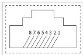
| Pin | 1 | 2 | 3 | 4 |
| GPI | GPI_1 | GPI_2 | NC | GPI_3 |
| Pin | 5 | 6 | 7 | 8 |
| GPI | GPI_4 | NC | NC | GND |
When connecting the GPI pin with ground, the setted function will be turned on, and goes out when disconnecting.
Example 1: Under “GPI” submenu, set “GPI control” to “On”, set “2 to “Red Tally”, when the pin 2 of the external GPI control unit is connected with ground, the Tally light will display on the front panel which will flashes in red around every second. When disconnected, the monitor will not display tally light information.
Example 2: Under “GPI” submenu, set “GPI control” to “On”, set to “Scan Mode”, when the pin 4 of the external GPI control unit is connected
with ground, the Scan mode will change and follow the sequence: “Normal” → “Overscan” → “Native”

6、UMD
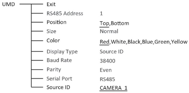
flowchart
graph TD
    A["UMD"] --> B["Exit"]
    A --> C["RS485 Address"]
    A --> D["Position"]
    A --> E["Size"]
    A --> F["Color"]
    A --> G["Display Type"]
    A --> H["Baud Rate"]
    A --> I["Parity"]
    A --> J["Serial Port"]
    A --> K["Source ID"]
    C --> L["1"]
    D --> M["Top,Bottom"]
    D --> N["Normal"]
    F --> O["Red,White,Black,Blue,Green,Yellow"]
    G --> P["Source ID"]
    H --> Q["38400"]
    I --> R["Even"]
    J --> S["RS485"]
    K --> T["CAMERA 1"]
Set "UMD":
(1) Select "Source ID"
(2) The underline flashes as a reminder on the bottom of the first letter. Revolve "MENU" to select the letters; the letter will follow the sequence of the down below if clockwise revolved:

flowchart
graph LR
    A["Space"] --> B["0~9"]
    B --> C["A~Z"]
    C --> D["a~z"]
    D --> E[&()*+,./:<><>
    end
(3) Press “MENU” to save the current settings letter and then start to set the next letter.
(4) Repeat step (2) and step (3), max 8 letters are supported.
(5) Press “Exit” to quit and save the settings.
7. Marker
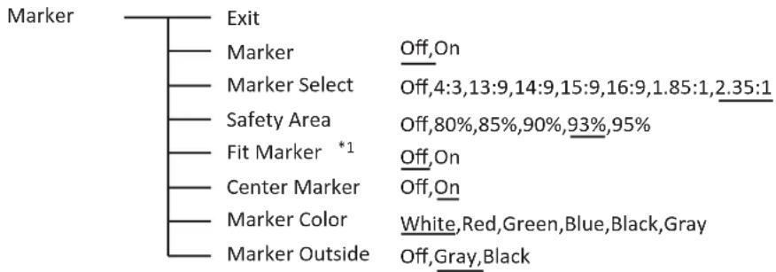
flowchart
graph TD
    A["Marker"] --> B["Exit"]
    A --> C["Marker Select"]
    A --> D["Safety Area"]
    A --> E["Fit Marker *1"]
    A --> F["Center Marker"]
    A --> G["Marker Color"]
    A --> H["Marker Outside"]
    C --> I["Off, On"]
    D --> J["Off, 4:3, 13:9, 14:9, 15:9, 16:9, 1.85:1, 2.35:1"]
    E --> K["Off, On"]
    F --> L["Off, On"]
    G --> M["White, Red, Green, Blue, Black, Gray"]
    H --> N["Off, Gray, Black"]
*1 When “Fit Marker” is “Off”, the size of safety area is benchmarked against the actual display screen, accounting for 80% \~ 95% of actual display screen. When “Fit Marker” is “On”, the size of safety area is benchmarked against the area inside the scales marker, accounting for 80% \~ 95% of the area inside the scales marker.
Example:
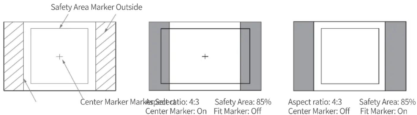
8. Audio
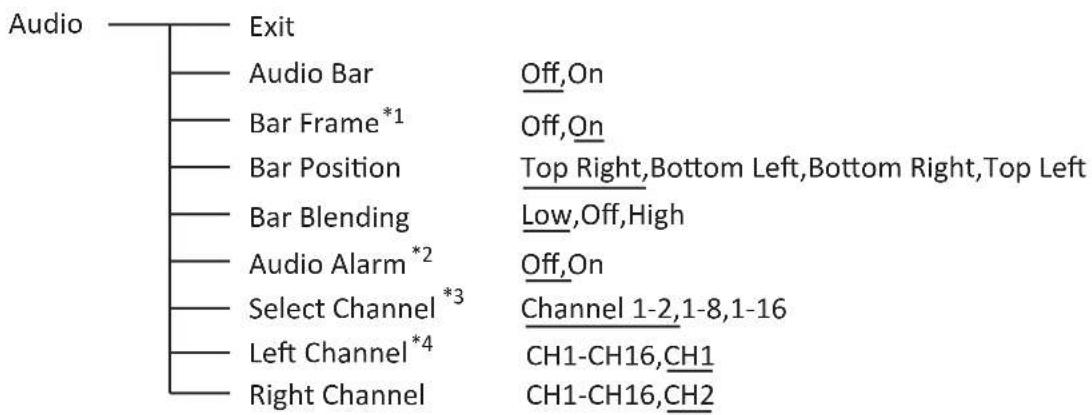
flowchart
graph TD
    A["Audio"] --> B["Exit"]
    B --> C["Audio Bar"]
    C --> D["Bar Frame*1"]
    D --> E["Bar Position"]
    E --> F["Bar Blending"]
    F --> G["Audio Alarm*2"]
    G --> H["Select Channel*3"]
    H --> I["Left Channel*4"]
    I --> J["Right Channel"]
    C --> K["Off,On"]
    D --> L["Off,On"]
    E --> M["Top Right,Bottom Left,Bottom Right,Top Left"]
    F --> N["Low,Off,High"]
    G --> O["Off,On"]
    H --> P["Channel 1-2,1-8,1-16"]
    I --> Q["CH1-CH16,CH1"]
    J --> R["CH1-CH16,CH2"]
*1 When “Bar Frame” is set to “Off”, only the audio meter will be displayed.
When “Bar Frame” is set to “On”, frame and real-time audio value will be displayed.
*2 Select Channel
Under HDMI signal, channel1-2 can be selected.
Under SDI signal, channel 1-2, 1-8 and 1-16 can be selected.
*3 When “Audio Alarm” is set to “On”, if no embedded audio is detected, the audio bar will display “UNLOCKED”. If the audio value is too low, the audio bar will display “MUTE”.
*4 Audio channels can be selected to output according to the requirements.
When the current “Select Channel” is set to “Channel1-2”, the left channel and right channel output can be selected from Channel1 or channel 2.
When the current “Select Channel” is set to “Channel1-8”, the left channel and right channel output can be selected from Channel1 to channel 8.
When the current “Select Channel” is set to “Channel1-16”, the left channel and right channel output can be selected from Channel1 to channel 16.
In audio bar, the left channel information will be in green, and the right channel information will be in red.
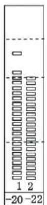
Channel 1\~2
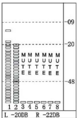
Channel 1\~8
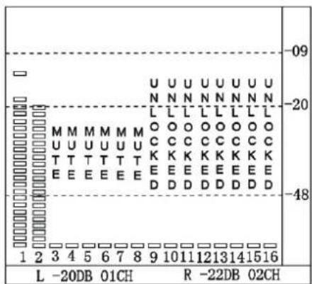
Channel 1\~16
9. Display
Display
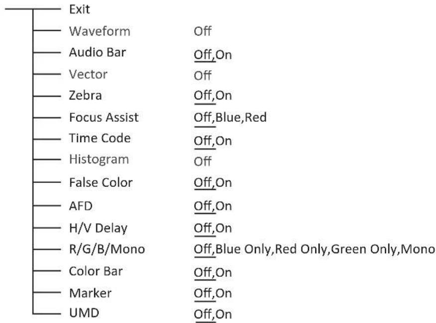
flowchart
graph TD
    A["Exit"] --> B["Waveform"]
    B --> C["Audio Bar"]
    C --> D["Vector"]
    D --> E["Zebra"]
    E --> F["Focus Assist"]
    F --> G["Time Code"]
    G --> H["Histogram"]
    H --> I["False Color"]
    I --> J["AFD"]
    J --> K["H/V Delay"]
    K --> L["R/G/B/Mono"]
    L --> M["Color Bar"]
    M --> N["Marker"]
    N --> O["UMD"]
    style A fill:#f9f,stroke:#333
    style O fill:#f9f,stroke:#333
10. System
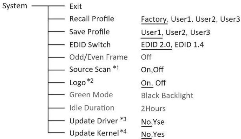
flowchart
graph TD
    A["System"] --> B["Exit"]
    B --> C["Recall Profile"]
    C --> D["Save Profile"]
    D --> E["EDID Switch"]
    E --> F["Odd/Even Frame"]
    F --> G["Source Scan *1"]
    G --> H["Logo *2"]
    H --> I["Green Mode"]
    I --> J["Idle Duration"]
    J --> K["Update Driver *3"]
    K --> L["Update Kernel *4"]
    C --> M["Factory, User1, User2, User3"]
    D --> N["User1, User2, User3"]
    E --> O["EDID 2.0, EDID 1.4"]
    G --> P["On, Off"]
    H --> Q["On, Off"]
    I --> R["Black Backlight"]
    J --> S["2Hours"]
    K --> T["No,Yse"]
    L --> U["No,Yes"]
\*1 Source Scan
When set to “On”, after turn on the monitor, the signal will be inspected and follow the sequence of “SDI1→SDI2→HDMI”.
For example: if channel is selected to SDI1, SDI1-IN has no input, and HDMI has input. When turn on the monitor, after automatic inspection, SDI1 has no recognized signal, and HDMI has recognized signal, then the input signal will be HDMI.
When set to "Off", update model will not be supported.
\*2 Logo
When powered on, the screen will display SWIT logo.
\*3.\*4 Update Driver/ Kernel
(1) Open the power supply, plug the U disk with upgrading programma into the USB port on the rear of the monitor;
(2) Press “MENU” rotary knob, open the main menu, enter the “system” submenu, select “Driver/Kernel”;
(3) Set the parameter to “Yes”, and press “MENU” rotary knob to begin upgrading;
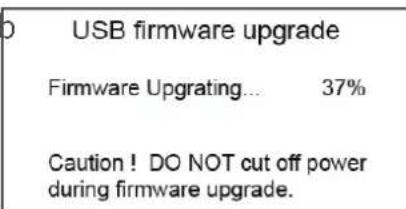
(4) While upgrading, there will be a progress bar displaying on the screen (Note: Do not power off when upgrading);
(5) After upgraded, the monitor will automatically reboot.
11. Color Measure
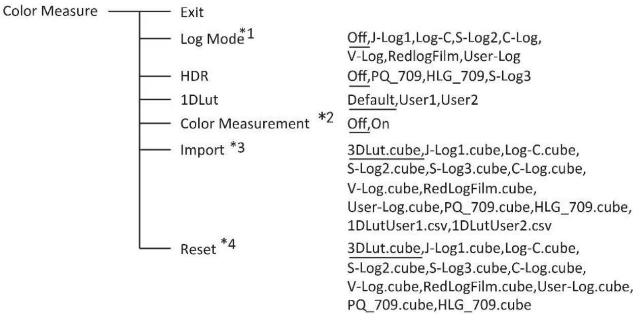
flowchart
graph TD
    A["Color Measure"] --> B["Exit"]
    A --> C["Log Mode*1"]
    A --> D["HDR"]
    A --> E["1DLut"]
    A --> F["Color Measurement *2"]
    A --> G["Import *3"]
    A --> H["Reset *4"]
    C --> I["Off,J-Log1,Log-C,S-Log2,C-Log,V-Log,RedlogFilm,User-Log"]
    D --> J["Off,PQ_709,HLG_709,S-Log3"]
    E --> K["Default,User1,User2"]
    F --> L["Off,On"]
    G --> M["3DLut.cube,J-Log1.cube,Log-C.cube,S-Log2.cube,S-Log3.cube,C-Log.cube,V-Log.cube,RedLogFilm.cube,User-Log.cube,PQ_709.cube,HLG_709.cube,1DLutUser1.csv,1DLutUser2.csv"]
    H --> N["3DLut.cube,J-Log1.cube,Log-C.cube,S-Log2.cube,S-Log3.cube,C-Log.cube,V-Log.cube,RedLogFilm.cube,User-Log.cube,PQ_709.cube,HLG_709.cube"]
\*1 Camera Log conversion
When shooting with Log mode of the camera, you can select the corresponding Log conversion LUT, to convert the log mode video to standard ITU Rec.709 mode to monitor. A "User-Log" is provided for user defined LUT converting to Rec.709.
\*2 HDR
CM-S73H supports three HDR modes: PQ_709、HLG_709、S-Log3.
\*3 Color measurement
Set the Color measurement parameter to “On” before color calibration, make sure the parameter set to “Off” after color calibration. When reboot, the Color measurement parameter automatically set to “Off”.
\*4 Import 3DLUT cube file
(1) Use a color analysis instrument and calibration software, and set to 6500K, Gamma2.4 for color calibration, this will generate a correct cube file (recommended Konica Minolta color analyzer CA-310 and Spectracal CalMAN software);
(2) Rename the cube file to "3DLut.cube" (attention to the cap letters), and copy to USB stick;
(3) Insert USB stick to the rear panel of the monitor. Select Operate Menu – Color Measurement – “Import” – “3DLut.cube” – “Yes” to import
(4) Import user needed Log Lut, User-log file and 1DLut by USB stick.
\*5 Reset to factory cubes
For any wrong cubes imported that caused wrong display colors, you can reset the cubes to factory cubes here.
12. OSD
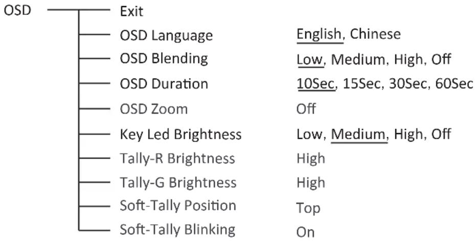
flowchart
graph TD
    A["OSD"] --> B["Exit"]
    B --> C["OSD Language"]
    B --> D["OSD Blending"]
    B --> E["OSD Duration"]
    B --> F["OSD Zoom"]
    B --> G["Key Led Brightness"]
    B --> H["Tally-R Brightness"]
    B --> I["Tally-G Brightness"]
    B --> J["Soft-Tally Position"]
    B --> K["Soft-Tally Blinking"]
    C --> L["English, Chinese"]
    D --> M["Low, Medium, High, Off"]
    E --> N["10Sec, 15Sec, 30Sec, 60Sec"]
    F --> O["Off"]
    G --> P["Low, Medium, High, Off"]
    H --> Q["High"]
    I --> R["High"]
    J --> S["Top"]
    K --> T["On"]
13. Key Inhibit

When the “Key inhibit” is set to “on”, there is no response when all the buttons except “MENU” is pressed, the screen will be displayed as “Key Inhibit”.
User can set “Key inhibit” to off under the “Key inhibit” submenu, restore the function of all keys.
Specification
| LCD Performance | ||
| Size | 7 inch | |
| Display area | 151.2×94.5 mm | |
| Resolution | 1920×RGB×1200 | |
| Color | 8 bit | |
| Aspect ratio | 16:9/4:3 | |
| Brightness*1 | 3000 cd/m2 | |
| Contrast | 1200:1 | |
| Viewing angle | Horizontal / Vertical: 160°/160° | |
| Input/Output | ||
| Input | HDMI×1 | HDMI input |
| BNC×2 | 3G/HD/SD-SDI input | |
| USB×1 | ||
| Output | HDMI×1 | HDMI output |
| BNC×1 | 3G/HD/SD-SDI loop output | |
| 3.5mm×1 | SDI/HDMI embedded audio output | |
| Video format | ||
| HDMI | 480i/576i/480p/576p | |
| 1080i (60/59.94/50) | ||
| 720p (60/59.94/50) | ||
| 1080p (60/59.94/50/30/29.97/25/24/23.98) | ||
| 1080psf (30/29.97/25/24/23.98) | ||
| 4096X2160 (60/50/30/25/24)3840X2160 (60/50/30/25/24) | ||
| SDI | SMPTE-425M-A/B | 1080p (60/59.94/50) |
| SMPTE-274M | 1080i (60/59.94/50) | |
| 1080p (30/29.97/25/24/23.98) | ||
| SMPTE-RP211 | 1080psf (30/29.97/25/24/23.98) | |
| SMPTE-296M | 720p (60/59.94/50) | |
| SMPTE-125M | 480i (59.94) | |
| ITU-R BT.656 | 576i (50) | |
| SMPTE-2048-2 | 2048×1080p (23.98/24/25/29.97/30/50/59.94/60)2048×1080i (50/59.94/60) | |
| Input voltage | DC/Battery: 6.5V~17V | |
| Power consumption | ≤26W | |
| Working temperature | -10°C~+50°C | |
| Working humidity | 10%~90% | |
| Storage temperature | -15°C~+60°C | |
| Storage humidity | 10%~90% | |
| Dimensions | 187×137×41mm | |
| Net weight (main body) | 500 g | |
*1 Only when the power supply voltage ≥slant 12V , the maximum brightness can reach to 3000 nit.
Trouble-shooting
| symptom | Possible causes Solution | |
| No display | The power is not turned on | Please check if the power is connected, and then press “POWER” button to turn on the monitor |
| Unstable power voltage | Reconnect to power supply | |
| BNC or HDMI cable loose contact or not correctly connected | Check and correctly connect the BNC or HDMI cable | |
| The attached battery is no power | Change battery | |
| Using DIY power supply but the polarity is reversed | Refer to the provided power supply, reconnect the power. | |
| Image or color abnormal | Bad contact of BNC or HDMI cable | Change cable |
| Video signal has Interference | Remove the interference source(s) | |
| Improper adjustment of the color parameters | Adjust the “Recall profile” to “Default” under “System” submenu | |
| Distortion of the image | Reset the Aspect ratio | |
| Set to Red/Green/Blue only or Mono | Turn the Blue only/ Red Only/ Green Only/Mono off under R/G/B/Mono submenu | |
| Turn on the “Focus Assist” function | Turn off the “Focus Assist” function | |
| Turn on the “False Color” function | Turn off the “False Color” function | |
| Signal can not correctly recognize color space, wrong set of HDMI color space. | Set to the correct color space mode | |
| No audio output | Set to Mute | Turn off MUTE or revolve “MENU/ENTER” to adjust the volume |
| Bad contact of signal cable | Connect to the correct input socket |
SWIT®
SWIT Electronics Co., Ltd.
Add: 10 Hengtong Road, Xin'gang, Nanjing Economic and Technological Development Zone, Nanjing 210038, P.R.China Tel: +86-25-85805753 Email: contact@swit.cc
SWIT Electronics Europe GmbH
Add: Hochstr. 17, 47228 Duisburg, Germany Tel: +49(0)20659799339 Email: info@swit-europe.com
SWIT Electronics America, Inc
Add: 3350 Scott Boulevard 61-02, Santa Clara, CA 95054, USA Tel: (408)260-8258, 1-866-986-SWIT(7948) Email: info@swit.us
- User Manual
- Preface
- SWIT Electronics Co., Ltd.
- Maintenance
- Warning
- The power
- The monitor
- Cleaning
- Contents
- Packing list
- Introduction
- Features:
- Operation Instruction
- Main menu settings
- Video Signal Interface
- External interface control
- Speaker
- Screen display
- Time code (SDI)
- (2)、UMD
- (3)、AFD (SDI)
- (4)、Soft Tally
- (5)、Audio
- 1、Zoom-in steps operation
- 2、Left and Right mapping
- 3、Up and Down mapping
- 4、Peaking precision adjust
- 5、Mapping indication window
- Introduction of audio and video functions
- • 16-ch embedded audio meters
- - Audio alarm
- • Time code (SDI)
- - Internal Color Bar
- - Peaking focus assist (red/blue switch)
- - Zebra stripes
- - Freeze Frame
- R/G/B/Mono
- False Color
- - AFD (SDI)
- H/V Delay (SDI)
- - Image flip
- Main menu
- Notice:
- Exit & Status
- Picture
- Color Temp
- 4、Function key
- 5、GPI
- 6、UMD
- Set "UMD":
- Marker
- Example:
- Audio
- Display
- System
- \*1 Source Scan
- \*2 Logo
- \*3.\*4 Update Driver/ Kernel
- Color Measure
- \*1 Camera Log conversion
- \*2 HDR
- \*3 Color measurement
- \*4 Import 3DLUT cube file
- \*5 Reset to factory cubes
- OSD
- Key Inhibit
- SWIT®
- SWIT Electronics Europe GmbH
- SWIT Electronics America, Inc
Brand : SWIT
Model : CM-S73H
Category : Monitor