
DriveRack 220i - Audio processor DBX - Free user manual and instructions
Find the device manual for free DriveRack 220i DBX in PDF.


| Product Type | Audio System Processor |
| Dimensions | 1.75 x 5.75 x 19 inches (44.45 x 146.05 x 482.6 mm) |
| Weight | 5.5 lbs (2.5 kg) |
| Power Supply | 100-120V or 220-240V AC, 50/60 Hz, 12 Watts |
| Inputs | 2 electronically balanced XLR (mic/line) with phantom power |
| Outputs | 2 electronically balanced XLR and Euroblock connectors |
| Frequency Response | 20 Hz - 20 kHz, ±0.5 dB |
| Dynamic Range | >110 dB A-weighted, >107 dB unweighted |
| THD+N | 0.003% typical at +4 dBu, 1 kHz, 0 dB gain |
| Processing | Advanced Feedback Suppression (AFS), GEQ/PEQ, Compressor, Limiter, AGC, Noise Gate, De-Esser, Ducker, Bandpass Filter, 2x2 Matrix Mixer, Delay, Subharmonic Synthesizer |
| Sampling Rate | 48 kHz |
| Latency | 0.6 ms |
| Control Interface | RS-232 (DB-9) for PC GUI, front panel buttons, Zone Controllers (ZC-1 to ZC-4) |
| Software | DriveWare GUI for Windows (98/NT 4.0+), program storage and editing |
| Construction | 1U rack-mount steel chassis |
| Safety & Compliance | RoHS, WEEE, FCC Part 15, IEC 60065, CE marked |
| Operating Environment | Indoor use, avoid moisture and extreme temperatures |
| Cleaning | Use a dry cloth; do not use liquids or sprays |
| User Serviceable Parts | None; all servicing must be performed by qualified personnel |
| Warranty | 2 years for original purchaser (US only) |
Frequently Asked Questions - DriveRack 220i DBX
User questions about DriveRack 220i DBX
0 question about this device. Answer the ones you know or ask your own.
Ask a new question about this device
Download the instructions for your Audio processor in PDF format for free! Find your manual DriveRack 220i - DBX and take your electronic device back in hand. On this page are published all the documents necessary for the use of your device. DriveRack 220i by DBX.
USER MANUAL DriveRack 220i DBX
System Processor with Advanced Feedback Suppression
220i
IMPORTANT SAFETY INSTRUCTIONS

WARNING: TOREDUCETHERISKOFFIREORELECTRIC SHOCKDO NOT EXPOSETHISEQUIPMENT TO RAIN OR MOISTURE
The symbols shown above are internationally accepted symbols that warn of potential hazards with electrical products. The lightning flash with arrowpoint in an equilateral triangle means that there are dangerous voltages present within the unit. The exclamation point in an equilateral triangle indicates that it is necessary for the user to refer to the owner's manual.
These symbols warn that there are no user serviceable parts inside the unit. Do not open the unit. Do not attempt to service the unit yourself. Refer all servicing to qualified personnel. Opening the chassis for any reason will void the manufacturer's warranty. Do not get the unit wet. If liquid is spilled on the unit, shut it off immediately and take it to a dealer for service. Disconnect the unit during storms to prevent damage.
SAFETY INSTRUCTIONS
NOTICE FOR CUSTOMERS IF YOUR UNIT IS EQUIPPED WITH A POWER CORD.
WARNING: THIS APPLIANCE SHALL BE CONNECTED TO A MAINS SOCKET OUTLET WITH A PROTECTIVE EARTHING CONNECTION.
THE CORES IN THE MAINS LEAD ARE COLOURED IN ACCORDANCE WITH THE FOLLOWING CODE:
GREEN aND YELLOW - EaRtH BLUE - NEUrRal BROWN - LIVE
AS COLOURS OF THE CORES IN THE MAINS LEAD OF THIS APPLIANCE MAY NOT CORRESPOND WITH THE COLOURED MARKINGS IDENTIFYING THE TERMINALS IN YOUR PLUG, PROCEED AS FOLLOWS:
- THE CORE WHICH IS COLOURED GREEN AND YELLOW MUST BE CONNECTED TO THE TERMINAL IN THE PLUG MARKED WITH THE LETTER E, OR WITH THE EARTH SYMBOL, OR COLOURED GREEN, OR GREEN AND YELLOW.
- THE CORE WHICH IS COLOURED BLUE MUST BE CONNECTED TO THE TERMINAL MARKED N OR COLOURED BLACK.
- THE CORE WHICH IS COLOURED BROWN MUST BE CONNECTED TO THE TERMINAL MARKED L OR COLOURED RED.
THIS EQUIPMENT MAY REQUIRE THE USE OF A DIFFERENT LINE CORD, ATTACHMENT PLUG, OR BOTH, DEPENDING ON THE AVAILABLE POWER SOURCE AT INSTALLATION. IF THE ATTACHMENT PLUG NEEDS TO BE CHANGED, REFER SERVICING TO QUALIFIED SERVICE PERSONNEL WHO SHOULD REFER TO THE TABLE BELOW. THE GREEN/YELLOW WIRE SHALL BE CONNECTED DIRECTLY TO THE UNITS CHASSIS.
| CONDUCTOR | WIRE COLOR | |
| Normal Alt | ||
| L LIVE BROWN BLACK | ||
| N NEUTRAL BLUE WHITE | ||
| E EARTH GND GREEN/YEL GREEN | ||
Warning: IF THE GROUND IS DEFEATED, CERTAIN FAULT CONDITIONS IN THE UNIT OR IN THE SYSTEM TO WHICH IT IS CONNECTED CAN RESULT IN FULL LINE VOLTAGE BETWEEN CHASSIS AND EARTH GROUND. SEVERE INJURY OR DEATH CAN THEN RESULT IF THE CHASSIS AND EARTH GROUND ARE TOUCHED SIMULTANEOUSLY.
WARNING FOR YOUR PROTECTION READ THE FOLLOWING:
KEEP THESE INSTRUCTIONS
HEED ALL WARNINGS
FOLLOW ALL INSTRUCTIONS
the apparatus shall not be exposed to dripping or splashing liquid and no object filled with liquid, such as vases, shall be placed on the apparatus.
CLEAN ONLY WITH A DRY CLOTH.
DO NOT BLOCK ANY OF THE VENTILATION OPENINGS. INSTALL IN ACCORDANCE WITH THE MANUFACTURER'S INSTRUCTIONS.
DO NOT INSTALL NEAR ANY HEAT SOURCES SUCH AS RADIATORS, HEAT REGISTERS, STOVES, OR OTHER APPARATUS (INCLUDING AMPLIFIERS) THAT PRODUCE HEAT.
ONLY USE ATTACHMENTS/ACCESSORIES SPECIFIED BY THE MANUFACTURER.
UNPLUG THIS APPARATUS DURING LIGHTNING STORMS OR WHEN UNUSED FOR LONG PERIODS OF TIME.
Do not defeat the safety purpose of the polarized or grounding-type plug. A polarized plug has two blades with one wider than the other. A grounding type plug has two blades and a third grounding prong. The wide blade or third prong are provided for your safety. If the provided plug does not fit your outlet, consult an electrician for replacement of the obsolete outlet.
Protect the power cord from being walked on or pinched particularly at plugs, convenience receptacles, and the point where they exit from the apparatus.
Use only with the cart stand, tripod bracket, or table specified by the manufacture, or sold with the apparatus. When a cart is used, use caution when moving the cart/ apparatus combination to avoid injury from tip-over.

Refer all servicing to to qualified service personnel. Servicing is required when the apparatus has been damaged in any way, such as power-supply cord or plug is damaged, liquid has been spilled or objects have fallen into the apparatus, the apparatus has been exposed to rain or moisture, does not operate normally, or has been dropped.
POWER ON/OFF SWITCH: The Power switch used in this piece of equipment DOES NOT break the connection from the mains.
MAINS DISCONNECT: The plug shall remain readily operable. For rack-mount or installation where plug is not accessible, an all-pole mains switch with a contact separation of at least 3 mm in each pole shall be incorporated into the electrical installation of the rack or building.
If connected to 240V supply, a suitable CSA/UL certified power cord shall be used for this supply.
This Equipment is intended for rack mount use only.
IMPORTANT SAFETY INSTRUCTIONS
ELECTROMAGNETIC COMPATIBILITY
This device complies with part 15 of the FCC Rules and the Product Specifications noted on the Declaration of Conformity. Operation is subject to the following two conditions:
• this device may not cause harmful interference, and
- this device must accept any interference received, including interference that may cause undesired operation.
Operation of this unit within significant electromagnetic fields should be avoided.
• use only shielded interconnecting cables.
U.K. MAINS PLUG WARNING
A molded mains plug that has been cut off from the cord is unsafe. Discard the mains plug at a suitable disposal facility.
NEVER UNDER ANY CIRCUMSTANCES SHOULD YOU INSERT A DAMAGED OR CUT MAINS PLUG INTO A 13 AMP POWER SOCKET.
Do not use the mains plug without the fuse cover in place. Replacement fuse covers can be obtained from your local retailer. Replacement fuses are 13 amps and MUST be ASTA approved to BS1362.

If you want to dispose this product, do not mix it with general household waste. There is a separate collection system for used electronic products in accordance with legislation that requires proper treatment, recovery and recycling.
Private household in the 25 member states of the EU, in Switzerland and Norway may return their used electronic products free of charge to designated collection facilities or to a retailer (if you purchase a similar new one).
For Countries not mentioned above, please contact your local authorities for a correct method of disposal. By doing so you will ensure that your disposed product undergoes the necessary treatment, recovery and recycling and thus prevent potential negative effects on the environment and human health.
DECLARATION OF CONFORMITY
Manufacturer's Name: dbx Professional Products
Manufacturer's Address: 8760 S. Sandy Parkway
Sandy, Utah 84070, USA
declares that the product:
Product name: dbx DriveRack 220i
Note: Product name may be suffixed by the EU.
Product option: None
conforms to the following Product Specifications:
Safety: IEC 60065-01+Amd 1
EMC:
EN
55022:2006
EN
55024:1998
FCC Part 15
Supplementary Information:
The product herewith complies with the requirements of the:
Low Voltage Directive 2006/95/EC
EMC Directive 2004/108/EC.
RoHS Directive 2002/95/EC
WEEE Directive 2002/96/EC
With regard to Directive 2005/32/EC and EC Regulation 1275/2008 of 17 December 2008, this product is designed, produced, and classified as Professional Audio Equipment and thus is exempt from this Directive.
Roger Johnsen
Director, Engineering
Signal Processing
8760 S. Sandy Parkway
Sandy, Utah 84070, USA
Date: May 31, 2012
European Contact: Your local dbx Sales and Service Office or
Harman Signal Processing
8760 South Sandy Parkway
Sandy, Utah
84070 USA
Ph: (801) 566-8800
Fax: (801) 568-7583
Introduction
0.1 - Defining the 220i System ......2
0.2 - Service Contact Info ....3
0.3 - Warranty 4
Getting Started
1.1 - Rear Panel 6
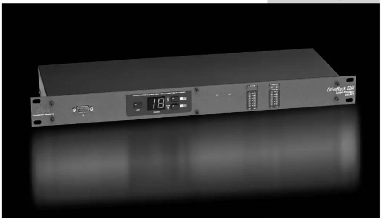
1.2 - Front Panel 7
1.3 - Connections 8
1.4 - PC GUI Installation ....8
Software Operation
2.1 - DriveRack 220i Philosophy ....10
2.2 - PC Connection ....10
2.3 - Views 10
2.4 - Configuration ....11
2.5 - Editing ....11
2.6 - Copy and Paste 12
2.7 - Meters and Mutes 12
2.8 - Loading 12
2.9 - Storing 13
2.10 - Importing and Exporting 13
2.11 - Utilities 14
2.12 - Online/Offline 14
2.13 - Preferences 14
Detailed Parameters
3.1 - Input Routing 16
3.2 - Pre-Matrix EQ 16
3.3 - Advanced Feedback Suppression .....18
3.4 - Automatic Gain Control (AGC) 20
3.5 - De-Esser 21
3.6 - Ducker 22
3.7 - Compressor 22
3.8 - Noise Gate 24
3.9 - Notch Filters 25
3.10 - Matrix Mixer 26
3.11 - Post-Matrix PEQ 26
3.12 - Bandpass Filter 28
3.13 - Limiter 28
3.14 - Delay 30
3.15 - Output 30
3.16 - Subharmonic Synthesizer ....31
Utilities
4.1 - Program List/Program Change 34
4.2 - ZC Setup 34
4.3 - Front Panel Lockout 36
Application Guide
5.1 - Mic Processing/Mixing 38
5.2 - Stereo/Dual Mono System Processing ....39
5.3 - Room Combining 40
5.4 - BGM/Paging 41
Appendix
A.1 - Factory Reset/Flash Update ....44
A.2 - Specifications 45
A.3 - Program List 46
A.4 - Block Diagram 47
A.5 - Gain and Relay Jumpers ....48
A.6 - Tips, Tricks and Troubleshooting ....49
A.7 - Zone Controller Wiring and Install 50
Introduction
INTRO
CUSTOMER SERVICE INFO
Defining the
DriveRack
WARRANTY INFO

natural_image
Front view of a DriveRack 220F drive station module with visible ports, display, and control buttons (no readable text beyond branding)dbx®
by HARMAN
Congratulations on your purchase of the dbx ^® 220i! The dbx 220i processor was designed to provide installers with programmable system processing along with dbx's Advanced Feedback Suppression ^TM (AFS ^TM ) algorithm for superior system control and performance. While the 220i offers all the tools necessary for processing a system, from EQ and De-Essing to Limiting and Ducking, the thing that sets this product apart from the competition is the inclusion of our patent-pending AFS ^TM algorithm that offers feedback filters with Qs up to 1/80th of an octave. This ensures that the music, or speech that comes in, goes out unblemished by the feedback detection and elimination process. In hundreds of demonstrations of this patent-pending algorithms, people have tried to discern between the original and processed signal, but to no avail.
Beyond the processing that the 220i is capable of, the 220i also offers control from the ZC series wall panel controllers. These controllers provide convenient remote control capability of Program change, Zone output volume and Muting. The zone controllers are easy to install using CAT5 cable and fit in standard wall boxes.
This manual will be your guide to understanding the full functionality of the powerful 220i. By combining the different components, the configuration possibilities are limitless. After you have become familiar with the unit, we encourage you to experiment and find the most effective and efficient way to run your system by utilizing the powerful processing of the 220i.
0.1 - Defining the 220i System
The dbx 220i is the most effective way to manage all aspects of post mixer processing and signal routing. The 220i essentially becomes the only device that you will need between the mixer and the power amps. The following are just some of the features of the 220i.
220i features:
• Advanced Feedback Suppression (AFS™)
• Graphic and Parametric EQ
- Compressor
- Limiting
• Auto Gain Control (AGC)
- Noise Gate
- De-Esser
- Ducker
- Bandpass Filters
- 2x2 Matrix Mixer
• 1.3 Seconds of Delay
• RS-232 PC GUI control
- Mic/Line Inputs
• Wall Panel Control
• Security Lockout
In addition to the amazing menu of processing available, the 220i also affords you the luxury of utilizing dbx Zone-Controller series wall-mounted control panels that will allow you to remotely control various parameters of the 220i. The ZC-1 offers remote programmable Volume control to any installation using the DriveRack 220i. The ZC-2 provides programmable Volume and Mute control. Both the ZC-1 and ZC-2 can be programmed to outputs of the DriveRack 220i. The ZC-3 allows Program Selection on the 220i. The ZC-4 also offers Program Selection via Contact Closure inputs for Room Combining applications. Up to six Zone Controllers can be used with a single DriveRack 220i, and can either be wired in series or parallel. The ZC-BOB was created to accommodate “home-run” or parallel wiring to the unit. With a maximum length of 1,000 ft., the Zone Controllers offer a simple way to create a simple yet elegant solution to many installation applications.

ZC-BOB

ZC-1

ZC-2
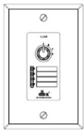
ZC-3
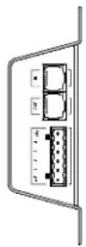
ZC-4
0.2 - Service Contact Info
If you require technical support, contact dbx Customer Service. Be prepared to accurately describe the problem. Know the serial number of your unit - this is printed on a sticker attached to the top panel. If you have not already taken the time to fill out your warranty registration card and send it in, please do so now.
Before you return a product to the factory for service, we recommend you refer to the manual. Make sure you have correctly followed installation steps and operation procedures. If you are still unable to solve a problem, contact our Customer Service Department at (801) 568-7660 for consultation. If you need to return a product to the factory for service, you MUST contact Customer Service to obtain a Return Authorization Number.
No returned products will be accepted at the factory without a Return Authorization Number.
Please refer to the Warranty information on the following page, which extends to the first end-user. After expiration of the warranty, a reasonable charge will be made for parts, labor, and packing if you choose to use the factory service facility. In all cases, you are responsible for transportation charges to the factory. dbx will pay return shipping if the unit is still under warranty.
Use the original packing material if it is available. Mark the package with the name of the shipper and with these words in red: DELICATE INSTRUMENT, FRAGILE! Insure the package properly. Ship prepaid, not collect. Do not ship parcel post.
0.3 - Warranty
- The warranty registration card that accompanies this product must be mailed within 30 days after purchase date to validate this warranty. You can also register online at www.dbxpro.com. Proof-of-purchase is considered to be the responsibility of the consumer. A copy of the original purchase receipt must be provided for any warranty service.
- dbx warrants this product, when purchased new from an authorized U.S. dbx dealer and used solely within the U.S., to be free from defects in materials and workmanship under normal use and service. This warranty is valid to the original purchaser only and is non-transferable.
- dbx liability under this warranty is limited to repairing or, at our discretion, replacing defective materials that show evidence of defect, provided the product is returned to dbx WITH RETURN AUTHORIZATION from the factory, where all parts and labor will be covered up to a period of two years. A Return Authorization number must first be obtained from dbx. The company shall not be liable for any consequential damage as a result of the product's use in any circuit or assembly.
- dbx reserves the right to make changes in design or make additions to or improvements upon this product without incurring any obligation to install the same additions or improvements on products previously manufactured.
- The foregoing is in lieu of all other warranties, expressed or implied, and dbx neither assumes nor authorizes any person to assume on its behalf any obligation or liability in connection with the sale of this product. In no event shall dbx or its dealers be liable for special or consequential damages or from any delay in the performance of this warranty due to causes beyond their control.
GetInG
StArteD

I.I - Rear Panel

IEC Power Cord Receptacle
The DriveRack 220i comes with a power supply that will accept voltages ranging from 100V-120V at frequencies from 50Hz-60Hz. An IEC cord is included. EU version accepts 220V-240V at frequencies from 50Hz-60Hz.
PC Connection
This DB-9 type null modem connection is used to send and receive information to and from the GUI interface.
NOTE: Front and rear PC connections should not be used at the same time as these connections are wired in parallel.
Zone Control Input (RJ-45 connector type)
This input connection is used to send information and power to the ZC wall controllers.
Inputs 1-2
The input section of the DriveRack 220i offers two electronically balanced XLR connectors mic/line inputs with Phantom Power.
Outputs 1-2
The output section of the DriveRack 220i offers two electronically balanced XLR connectors. In addition, the 220i offers Euroblock input connector options.
Signal/Clip LED
This LED is used to indicate microphone signal input or clip.
Mic Gain Control
This knob is used to set the input gain for the microphone input.
Line/Mic Selector
This switch is used to select either a line or microphone input.
1.2 - Front Panel

PC Connection
This DB-9 type connection is used to send and receive information to and from the computer running the DriveWare ^TM software.
NOTE: Front and rear PC connections should not be used at the same time as these connections are wired in parallel.
Load Button
The load button is used to load the selected program.
Program Display
This program display is used to indicate the currently selected program of the 220i.
Program Up and Down (Filter Clear Ch1 and Ch2)
These program up and down buttons are used to scroll through the program menu of the 220i. Pushing and holding these buttons will clear the live filters on these channels if there are AFS modules in the signal path.
PC LED
This LED (when lit), indicates that the 220i is connected to the PC. When it is flashing, the 220i is sending/receiving information from the PC.
CLIP LED
This LED (when lit), .indicates that a signal is clipping, either in the analog input section, or in the DSP.
Input Meters
These meters monitor the signal level at the output of the A/D converter.
Threshold Meters
The threshold meters indicate that the threshold level has been crossed within the output dynamics section. The tri-color LED will be green when the signal is below the threshold for a Compressor, Limiter and AGC, and above the threshold for the Gate. Yellow indicates that the signal is in the overeasy region in the Compressor or Limiter and within the Window of the AGC. Red indicates that the signal has passed over the threshold for the Compressor, Limiter and AGC, or below the threshold for the Gate.
Output Meters
These meters monitor the signal level at the input of the D/A converter.
1.3 - Connections

- When setting up the DriveRack 220i, make connections as follows:
• Always make connections prior to applying power to the unit. - Connect the output from the sending device (mixer) to either of the two XLR input connectors shown below.
- Make output connections from any one of the 2 output XLR or Euroblock connectors shown below to the input of the selected power amps.
- It is recommended that the power amps are turned off prior to cycling power to the DriveRack 220i. Always make sure that your power amps are the last item turned on and the first turned off.
Once all of the connections have been made and the unit is powered up, you can navigate through the entire signal path of the DriveRack 220i from the included DriveWare GUI. The display provides you with a clear and concise overview of each aspect of the signal path from the input to the output section.
I.4 - PC GUI Installation
Minimum System Requirements
• 266MHz processor
• Windows 98 edition 2 or Windows NT 4.0
16 bit color
• 64 meg RAM
Installation
• Install DriveWare from the included CD ROM or download DriveWare from the dbx website at www.dbxpro.com.
- After clicking on the “.exc” install file, follow the instructions in the installer. The application will proceed to prompt you for the installation location.
- Once the software installation is complete, it is recommended that you restart your computer.
SoFtWAre oPerAtlon

natural_image
Front view of a DriveRack 220i System Processor with visible drive, ports, and digital display (no readable text or symbols beyond branding)For your convenience, all editing functions of the DriveRack 220i are performed via the included Driveware GUI. This section has been created to act as a tutorial for performing various editing aspects of the unit.
2.1 - DriveRack 220i Philosophy
The philosophy of the DriveRack 220i is built around the idea of a program.
Programs
A program consists of processing modules configured to form the desired signal path. The processing modules and all their parameters are saved as part of the program. The quickest way to get up and running with the DriveRack 220i is to select one of the programs that are already configured. If modifications are needed then the program can be reconfigured to select the appropriate processing modules and parameters can be edited to taste. All module parameters are part of the program and as such they are saved off when the program is stored. These parameters are also saved as part of the program file when the program is exported to a computer.
Utilities and Mutes
Utilities and Mutes are global functions and are independent of the program. Utilities and Mutes are not saved as part of the program when it is stored but they can be saved as part of the device file. This can be helpful as Utilities can be set up just once rather than having to set up the utilities for each program. The same applies to Mutes; output Mutes can be used regardless of the program that is being recalled. If the need arises to mute an output as part of a program and have that level remain with the program, the output level can be set to -inf in the Matrix Mixer. This means that no matter whether the output mute is engaged or not, that output will have no output level.
2.2 - PC Connection
Once the software has been loaded and the DriveRack unit is connected via the included Null Modem cable, run the DriveWare Graphic User Interface (GUI) by double clicking on the application icon. You will see the DriveWare window open with an icon of the DriveRack 220i unit. Double clicking on the unit will open the unit to the program screen where you will be able to see the processing modules and the configuration.
2.3 - Views
There are three different views within the DriveWare GUI; Venue view, Unit view, and Module view. Venue view provides you with an overall system view of the DriveRack network including other DriveRack units if you are using 480 series DriveRack units that can be networked together. Double clicking on a unit icon in the Venue view takes you to the Unit view. Unit view (often called program screen) provides you with a graphic representation of the configuration of the individual DriveRack unit, including all the processing modules and their positions in the signal path. Unit view offers access to meters and output muting, program selection and loading, processing configuration, program import and export, program storing, as well as utility menu control. Double clicking on the processing module takes you to the Module view. Module view (also called edit screen) provides access to the processing and utility parameters. Editing of parameters is done in Module view.
2.4 - Configuration
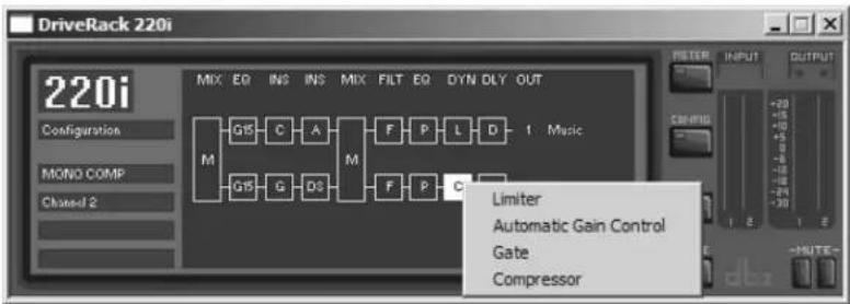
Configuration of the DriveRack units is done in Unit view. The DriveRack 220i configuration can be changed by clicking on the CONFIG button. Once the CONFIG button has been clicked, the modules can be changed by right clicking on the module to be changed. For example, if you want to change the processing module in one of the inserts, you simply right-click on that module and you will be able to select another processing block as well as unlink that module (if it is stereo linked). To link modules in stereo, click on one of the module that you want to link. While holding the Ctrl button click the other module that you want to link it to; both modules should now be highlighted. By right-clicking on either module you can now select LINK. Once the desired configuration is created you must click the CONFIG button once more to load the configuration.
flowchart
graph TD
    A["Configuration"] --> B["M"]
    C["MONO COMP"] --> B
    D["Channel 2"] --> B
    B --> E["G15"]
    B --> F["G15"]
    B --> G["G"]
    B --> H["G3"]
    B --> I["A"]
    B --> J["M"]
    J --> K["F"]
    J --> L["P"]
    J --> M["L"]
    J --> N["D"]
    J --> O["1 Music"]
    J --> P["F"]
    J --> Q["P"]
    J --> R["C"]
    S["Driver Rack 220i"] --> T["Mix EQ INS INS MIX FILT EQ DYN DLY OUT"]
    U["Limiter"] --> V["Automatic Gain Control"]
    W["Gate"] --> X["Compressor"]
2.5 - Editing
To edit a processing module double click on that module. Adjust the module to taste; make sure that the module is engaged, this is usually indicated by the module on button in the upper left corner of the parameter section. Although process editing is done in real-time, the changes can either be discarded or accepted by selecting the OK or CANCEL button.
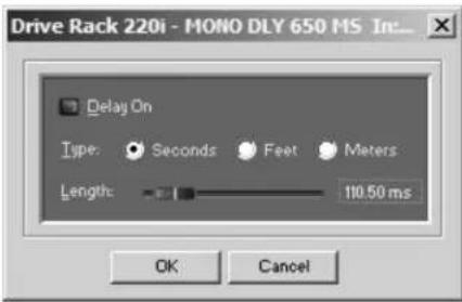
2.6 - Copy and Paste
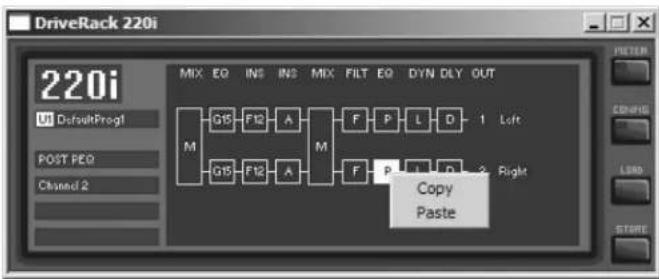
Parameters can be copied and pasted between channels in the DriveRack devices. From the program screen right click on the module that you want to copy and select Copy. To paste, right click on a like module and select Paste. Obviously you cannot copy parameters to and from unlike modules, for example from a Compressor to a Parametric EQ.
flowchart
graph TD
    A["M"] --> B["G15"]
    A --> C["F12"]
    A --> D["A"]
    A --> E["M"]
    E --> F["F"]
    E --> G["P"]
    E --> H["L"]
    E --> I["D"]
    E --> J["1 Left"]
    E --> K["Right"]
    L["Copy Paste"] --> M
2.7 - Meters and Mutes
The input and output level meters and mute buttons can be seen by clicking on the METER button in the upper right corner of the program screen. Outputs can be muted by clicking on the mute buttons.

flowchart
graph TD
    A["Input"] --> B["M"]
    B --> C["Q15"]
    B --> D["G"]
    B --> E["C"]
    B --> F["A"]
    B --> G["M"]
    B --> H["F"]
    B --> I["P"]
    B --> J["L"]
    B --> K["D"]
    B --> L["1"]
    B --> M["Music"]
    B --> N["2"]
    B --> O["Macrophone"]
2.8 - Loading
The LOAD button is used for loading one of the programs in the program table. Right click on the program name (directly below the large 220i in the upper left hand corner of the Unit view), to see a list of programs. Select one of the programs by clicking on it. At this point this new program is not loaded; to load this program click on the load button.

2.9 - Storing
Programs can be stored in the DriveRack unit or saved on the computer. To store a program in the DriveRack unit the GUI software must be on-line with the unit. The DriveRack 220i allows both program naming and along with that name you can also select where in the user program table you would like to store the program. Clicking the STORE button enters the store routine where a name for the program can be entered. Under the name lies the Program Table position selector for this new program. To complete the storing process, make sure that the “Replace an Existing Program” button is selected and click OK.

2.10 - Importing and Exporting
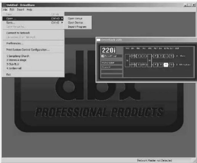
To save a program to your computer click on File on the Menu Bar and select Save, then select Export Program – you are exporting a program from the DriveRack unit to the computer. You will then be taken to a folder where you can save this DriveWare Program (.dwp). You can also save the DriveRack device file (.dwd). The difference between the device file and the program file is the device file saves all the utility information in addition to the program information. To import a program from the computer select File on the Menu Bar and click on Open, then select the file you would like to import to the DriveRack unit.
2.11 - Utilities
The DriveRack 220i utilities can be entered by clicking on Edit on the Menu Bar and selecting Utilities.

2.12 - Online/Offline
The DriveWare GUI provides a mechanism for creating programs while not physically connected to the DriveRack unit. The GUI can be opened and a DriveRack unit can be inserted using the Insert menu from the Menu Bar. The unit can be configured and edited just the way a real unit can. The program can then be Exported to the computer and saved.
2.13 - Preferences
Preferences can be found by clicking on File on the Menu Bar. Preferences allow you to change your communication preferences. It is recommended that you not adjust these unless there is a specific problem that is keeping you from connecting to the DriveWare GUI.

Detailed Parameters
DetAILeD PARAmeterS
natural_image
Front view of a DriveRack 220i System Processor with I/O ports and digital display (no readable text or symbols beyond branding)The 220i DriveRack offers complete editing flexibility, by offering in-depth control over every parameter within each effect module. The following section will provide you with a module block representation for each effect, as well as descriptions and explanations of all parameters within the 220i.
3.1 - Input Routing
The signal routing begins at the INPUT ROUTING block of the 220i. These parameters are user adjustable on all programs.
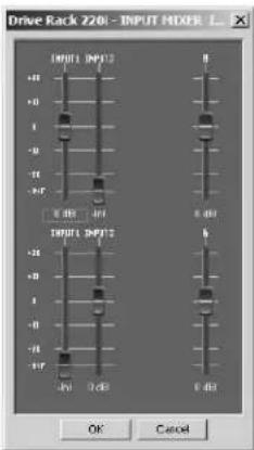
Input I Level -Inf to 20dB
Adjusts the input level from analog input one.
Input 2 Level -Inf to 20dB
Adjusts the input level from analog input one.
Level Left or Right Inf to 20dB
This parameter is used to adjust the level for the selected channel.
3.2 - Pre-Matrix EQ
The 220i's Pre-matrix EQ section may be configured as a single or linkable 15-band or 28 band graphic EQ or 9-Band PEQ.
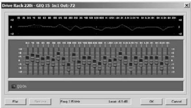
GEQ
EQ On/Off
Turns the EQ on and off.
Flatten/Restore
This parameter either flattens the GEQ or restores the GEQ to the last setting before flattening. The DriveRack unit allows you to leave the EQ edit window and return without losing the edited EQ settings.
Frequency (F) 31.5Hz to 16.0kHz
This parameter allows you to select any one the 28 available frequencies.
Gain (G) -12 to +12 dB
This parameter allows you to adjust the level of any one of the 28 bands of the GEQ in .5 dB increments.
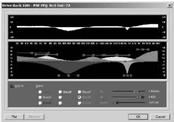
PEQ
EQ On/Off
Turns the PEQ on and off.
Flat Set/Undo
This parameter either flattens (set) or restores (undo) all bands to their original settings.
Band I Frequency 20 to 20kHz (Low Shelf)
Selects the frequency of the low pass shelf parametric E.Q.
Slope I 3-12dB/Octave
Sets the slope of the low shelf parametric EQ.
Level 1 -12 to 12 dB
Sets the overall gain of the shelf EQ.
Band (2-8) Frequency 20 to 20k
Selects the frequency of the selected band of the parametric EQ.
Q (2-8) 0.105 to 16.0
Q is adjustable from 0.105 to 16.000
Level (2-8) -12 to 12 dB
Sets the overall level of the selected parametric EQ frequency.
Band 9 Frequency 20 to 20k (High Shelf)
Selects the frequency of the high shelf parametric EQ.
Slope 9 3-12dB/Octave
Sets the slope of the high shelf parametric EQ.
Level 9 -12 to 12 dB
Sets the overall gain of the high shelf parametric
3.3 - Advanced Feedback Suppression
The 220i offers the exclusive patent pending AFS (Advanced Feedback Suppression) feedback elimination module. Feedback is caused when a microphonic signal such as a guitar pickup or microphone is reproduced by an amplification and is repeatedly picked up in phase. The AFS uses Precision Frequency Detection and state-of-the-art processing to determine the exact portions of a given frequency of your feedback that need to be removed (instead of taking out large sections of your sound). The AFS module of the 220i allows the user to optimize the elimination of feedback. In the past, graphic equalizers were used to eliminate feedback from a system. This was an acceptable method for eliminating feedback, but when this method was precision tested, the result clearly showed that a single 1/3 octave EQ slider was removing approximately half of the signal power. With the AFS, the module removes the feedback automatically and the proprietary, precision AFS filters remove only a fraction of the frequency spectrum. The following diagram shows AFS as opposed to competing, competitive feedback eliminators and conventional graphic EQs:

AFS On/Off
Turns the AFS module on and off. If AFS is Off, the filters are bypassed, and the algorithm is halted (the filters are not updated). If AFS is On, the filters are active, and the they are updated according to the current selected mode (Fixed or Live).
Clear Live/All
This parameter clears the filters. If Clear Live is selected, then (if invoked) the live filters are reset. If Clear All is selected, then (if invoked) all of the filters are reset. When either Clear Live or Clear All is selected, the third parameter row displays "Start w/ Data Wheel."
Mode - Live or Fixed
When the mode is Fixed, the algorithm updates only the fixed filters. When the mode is Live, the algorithm updates only the live filters. In FIXED mode, the filters are automatically assigned to a frequency creating feedback fixed filters that are stored remain with the program and at that frequency until cleared by the user. Fixed mode is used before the performance without any input signal. In LIVE mode, the live filters automatically detect and remove feedback during the performance. When all of the live filters have been used, they begin to round robin. Essentially this means that the first filter set is replaced where a new feedback is detected and notched out. This mode is useful because feedback frequencies may change as the microphone is moved, and/or as the characteristics of the venue change. Note- Only the fixed filter settings will be stored with the program.
Type - Speech, Low Music, Medium Music and High Music
Type allows the AFS algorithm to be customized for the application. The Values correspond to different Q and sensitivity settings. Values are; Speech (Q=7.25), Music Medium (Q=29), Music High (Q=128).
NOTE: Because lower frequencies have longer wavelengths, it is sometimes more difficult to find the exact feedback frequency; as a result the AFS algorithm will sometimes use a slightly wider Q filter to notch low frequency feedback.
Total Number of Filters I-12
This parameter selects the number of filters being used
Number Fixed - 0-12
This sets the number of fixed filters. This sets the number of Fixed AFS filters and ranges from 0-12. This also sets the number of Live filters as the Total number of filters - number of Fixed Filters = number of Live Filters.
Live Filter Lift (On/Off)
This parameter turns the Live Filter Lift on and off.
Lift After - 5 sec to 60 min
This parameter allows the user to setup the box so that the Live filters will automatically be removed after a set time (as indicated by the "Lift After" parameter). It ranges from 5 seconds to 60 minutes. This feature is useful if the microphone being used is moved or the characteristics of the venue change over time. This feature removes unnecessary filters from the spectrum to increase sonic quality.
Virtual Highpass 0.00-410.1Hz
This parameter sets a highpass filter in the path of the AFS detector. There may be occasions where the AFS algorithm is removing too much low end because it is being triggered by Synthesizer or Bass notes that are not really feedback. This parameter provides a mechanism to make the AFS algorithm less sensitive to low frequency thereby setting fewer filters in the bass region.
Sensitivity -20-+20dB
The AFS algorithm is very effective when the audio has a nominal level of 0 dBu, however if the audio is too low in level the AFS algorithm may not catch feedback as quickly as possible. By increasing or decreasing the sensitivity you can adjust for audio that is either too loud or too soft and help the AFS function properly.
3.4 - Automatic Gain Control (AGC)
The AGC is used to keep the average level of a signal at a constant level. This is done by selecting a desired Target output level and Window. The AGC keeps the signal within the Window about the selected Target by slowly adjusting the gain. The maximum gain that can be applied to the signal is selected by the Gain parameter. When the input signal falls below the Low Threshold the AGC releases the gain and returns to unity. This prevents the AGC from adding gain when there is no signal present and raising the system noise floor. High level signals are reduced by a fast limiter to prevent distortion by clipping. The AGC Threshold meters show what region of the AGC the input signal is in. The T' (yellow) indicates the signal is within the Window. A + (red) indicates the signal is going into the Limiter. A - (green) indicates the AGC is adding Gain and is at or below the window. When the Threshold meter is off the signal is below the Low Threshold.

AGC: On/Off
Turns the AGC module On and Off.
Target: -20 to 20 dB
The Target parameter defines where you would like the average level of the AGC output to be. If the average level of the signal rises above the Target the gain will be reduced. For signals with an average level below the Target the gain will be increased.
Gain: I to 20dB
This adjusts the maximum amount of gain that can be added by the AGC.
Window: I to 10dB
This adjusts the amount of variation in the output
Low Threshold: -60 to -30dB
The Low Threshold sets a lower limit to the AGC. This prevents the AGC from adding gain to low level signals or noise.
Attack: 0.20 to 5 Seconds
This adjusts how fast the AGC will increase gain.
Release: 30.0 to 1 dB/Second
This adjusts how fast the AGC will reduce gain.
3.5 - De-Esser
The 220i offers a dedicated De-Esser module. This De-esser effect is ideal for removing unwanted vocal sibilance.. These parameters are user adjustable on all programs and are as follows:

De-Esser On/Off
Turns the De-Esscr on or off.
Freq. 800 Hz to 8.00 kHz
This is the center frequency the De-Esser uses when in Band Pass mode or the corner frequency used when in High Pass mode.
Amount 0 to 100%
This controls the amount of De-Essing. The amount control is very much like a combination threshold/ratio control. A higher amount applies more De-Essing to the signal.
Type HP or BP
Selects the type of filter used by the De-Esser.
Width
Sets the Q of the Band Pass Filter.
3.6 - Ducker
The Ducker provides a method for attenuating the signal in one channel when a signal is present in the other channel.

Ducker On/Off
Turns the Ducker on or off.
Threshold -40 to +20dBu
Threshold is the level from signal path A at which the Ducker will begin attenuating the signal passing through the Ducker (signal path B).
Amount -0 to 6dB
This parameter sets the amount sets the amount of attenuation.
Attack 0.1 m Sec to 200 m Sec
Attack is how quickly the signal is attenuated in the second channel when a signal is present in the first channel.
Hold 0 to 500 m Sec
Hold time is the length of time after the signal in the first channel goes below the threshold that the attenuation is applied to the signal in the second channel.
Release 360 dB / Sec to 5 dB / Sec
Release is how quickly the attenuated signal returns to its nominal level.
3.7 - Compressor
The 220i also offers a dedicated compression module. The Compressor is a full bandwidth Stereo Compressor inserted prior to the Crossover. The Compressor is the perfect tool for tightening uneven signal sources such as vocals and guitars. The parameters for the Compressor are as follows.

Compressor On/Off
Turns the Compressor module on and off.
OverEasy (O) Off to 10
There are ten levels of OverEasy ^® that can be used for the limiters. The point when the compressor starts to compress is the “knee.” When the compressor starts to reduce the level of a signal abruptly as it passes over the threshold, this is called “hard knee” compression. OverEasy ^® (soft knee as it is sometimes called) is when the volume of the sound is compressed gradually. OverEasy ^® compression starts to compress before the level of the signal reaches the
threshold and reaches full compression after the level has gone above the threshold. OverEasy ^® compression, by its very nature, sounds much smoother and more natural and will be used for most applications. When it is gentle (natural sounding or light) compression that you are looking for, the compressor offers VariKncc ^TM . VariKncc ^TM gives you ten levels of OvcrEasy ^® compression to choose from (1 being almost hard knee and 10 being the most OvcrEasy ^® ). This lets you choose the exact knee that is needed for the dynamic effect you are looking for.
Threshold (T) -40 to +20dBu
Threshold is the signal level at which the unit starts to compress the signal. If the level is set to -10 dBu, than any signal larger than -10 dBu is compressed while any signal that has a level that is lower than -10dBu is left at the same signal level. Light compression is where only the loudest parts of the signal go over the threshold. Very heavy compression can be achieved by setting the threshold low enough that almost the entire signal content is over the threshold. For most signals the most natural compression is achieved when most of the signal content remains just below the threshold and only the peaks cross the threshold.
Ratio (R) 1.0 to Inf:1
Ratio is the amount the unit reduces the signal level of the sound that is above the threshold. A 2:1 ratio means that if the incoming signal is 2dB over the threshold the unit will compress the signal, and outputs a signal that only goes 1dB over the threshold. For light compression choose a lower ratio, while a heavy compression requires a higher ratio. A setting of Inf:1 makes the compressor act as a limiter.
Gain (G) -20 to +20 dB
This parameter is used to compensate for the gain lost during compression. By using heavy compression on a signal and then boosting the signal with the output gain, the user can create a signal that sounds much louder than it actually is.
Auto On/Off
When Auto Mode is on, the220i automatically sets the Attack, Hold, and Release times for the signal. The auto mode constantly adjusts these parameters in real time for optimum performance from the unit. You will find that for most applications, not only is using the auto mode faster and easier but by letting the unit constantly tweak these parameters for you will result in a better end result (try and hit a snare exactly the same for three minutes).
Attack 0.1 m Sec to 200 m Sec
Attack is how fast the compressor starts to compress the signal after it passes the threshold. Fast attack is useful when dealing with lots of fast transients. The attack control is not active when in auto mode.
Hold 0 to 500 m Sec
Hold is the time the 220i remains in compression after the signal has dropped below the threshold. A longer hold time is useful in smoothing out the sound when compressing several fast peaks that are fairly close together in time. In general some hold time helps to make the compression sound more natural but too much can over compress your signal making for an unwanted drop in level. The hold control is not active while in auto mode.
Release 360 dB / Sec to 5 dB / Sec
Release is how fast the 220i comes out of compression. The release is in dB per second. For example, if release is set to 5 dB /sec, and the signal is at 10dB of gain reduction, the release time is 2 seconds. Too fast a release time can result in an audible volume jump, while too slow a release time can result in the compression of signal that is not above the threshold. This can cause volume drops in your signal that may not be desired. The release control is not active while in auto mode.
3.8 - Noise Gate
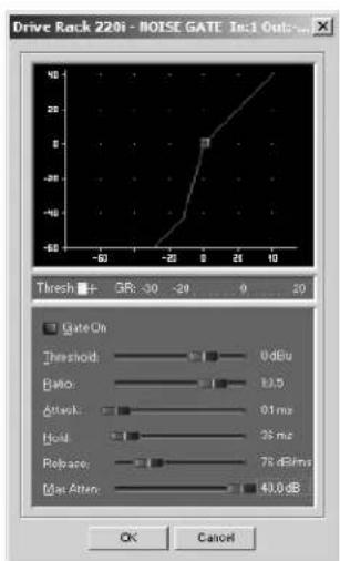
Gate On/Off
Turns the Gate on and off.
Threshold -50 to 20 dBu
The threshold is the volume level at which the gate opens. Anything above the threshold passes, while signal that is lower than the threshold is attenuated. Beware, setting the threshold to high can cut off the tail end of signals as they fade out (the sustain of a guitar note, a held piano chord, a reverb tail, etc.).
Ratio 1:1.0 to 1:15
This is where you decide how much downward expansion you want. This ratio works opposite from that of the compressor or limiter. If a ratio of 1:4 is selected, a signal that is 1dB below the threshold will be reduced in gain so that it becomes 4dB below the threshold.
Attack 0.1 to 200 m Sec
As the signal reaches the threshold area, the Attack control sets the speed at which the gate opens. Use very fast attack times to catch the fronts of transient signals.
Hold 0 to 500 m Sec
The Hold control sets the amount of time the gate is held open after the signal passes below the threshold point.
Release 360 to 5 dB
Release sets the speed at which the gate "closes" or attenuates when the end of the Hold time is reached.
Max ATT 0 to Inf. dB
This sets the maximum amount of attenuation for the gate.
3.9 - Notch Filters
The notch filter is the perfect tool for dropping out undesirable frequencies that may appear in the input signal.
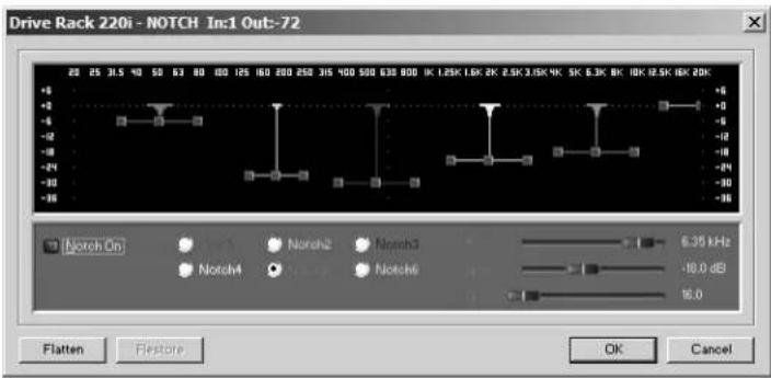
Notch On/Off
Turns the notch filters on and off.
Frequency (1 to 6) 20 to 20K
Selects the desired notch filter frequency of the selected notch filter.
Gain -36 to 6 dB
Sets the level of the selected notch filter. Set to +6dB to help find unwanted feedback, then set to -3dB to -36dB to remove.
Q 16 to 128
Selects the Q of the selected notch filter.
3.10 - Matrix Mixer
This adjusts the mix and output levels of the 220i. If there is a Ducker in the signal path this also provides for bypassing the ducker module to one or both outputs.

Input A Level -Inf to 20dB
Adjusts the level from signal path A.
Input B Level -Inf to 20dB
Adjusts the level from signal path B.
Output I Level -Inf to 20dB
Adjusts the output level of Output 1.
Output 2 Level -Inf to 20dB
Adjusts the output level of Output 2.
3.11 - Post-Matrix PEQ
In addition to the pre-matrix EQ options within the signal path, the 220i also offers a 4-band parametric EQ after the matrix section. The parameters for the post-matrix EQ are as follows and are user adjustable.

PEQ On/Off
Turns the PEQ band on and off.
The following figure shows the constant Q parametric filter.

line
| Frequency | Magnitude | | --------- | --------- | | 10^1 | 0 | | 10^2 | 0 | | 10^3 | 12 | | 10^4 | 0 |Flatten/Restore
This parameter either flattens the PEQ or restores the PEQ to its original shape.
Type
This parameter selects the PEQ type. Types include: 1. Bell-All parametrics are bell-shaped 2. HShelf - One shelf is High, while all others are bell 3. LShelf - One shelf is Low, while all others are bell and 4. LHShelf - One shelf is High and one is Low, and the others are bell.
Band (I-4) Frequency 20Hz to 20kHz
Selects the frequency of the selected band of the parametric EQ.
Level (1-4) -12dB to 12dB
Sets the peak level of the selected parametric EQ.
Q (I-4) 0.20 to 16 dB
Sets the Q or Bandwidth of the selected Parametric EQ.
3.12 - Bandpass Filter
This Bandpass Filter module allows the user to adjust the output bandwidth.
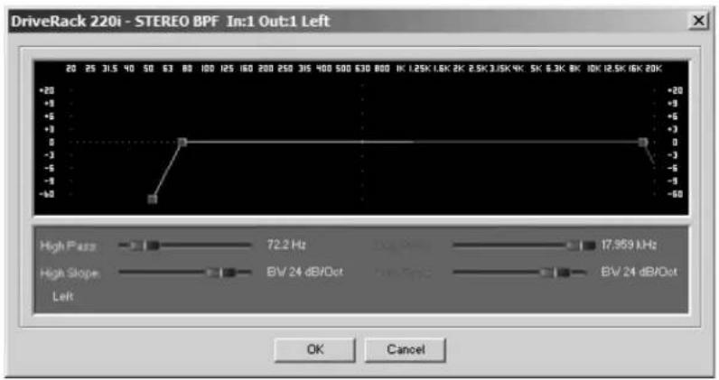
Highpass Out to 20kHz
Adjusts the lowest frequency that the output will achieve.
Lowpass Out to 20Hz
Adjusts the highest frequency that the output will achieve.
3.13 - Limiter
The 220i offers a dedicated Limiter module. The Limiters are located on each output channel and have been strategically placed for speaker and amplifier protection.

Limiter On/Off
Turns the Limiter module on and off.
OverEasy (O) Off to 10
There are ten levels of OverEasy ^® that can be used for the limiters. The point when the compressor starts to compress is the “kncc.” When the compressor starts to reduce the level of a signal abruptly as it passes over the threshold this is called “hard knee” compression. OverEasy ^® (soft knee as it is sometimes called) is when the volume of the sound is compressed gradually. OverEasy ^® compression starts to compress before the level of the signal reaches the threshold and reaches full compression after the level has gone above the threshold. This OverEasy ^® compression, by its very nature sounds much smoother and more natural and will be used for most applications. When it is gentle (natural sounding or light) compression that you are looking for, the compressor offers VariKncc ^TM . VariKncc ^TM gives you ten levels of OverEasy ^® compression to choose from (1 being almost hard knee and 10 being the most OverEasy ^* ). This lets you choose the exact knee that is needed for the dynamic effect you are looking for.
Threshold (T) -40 to +20dBu
Threshold is the signal level at which the unit starts to compress the signal. If the level is set to -10 dBu, any signal larger than -10 dBu is compressed while any signal that has a level that is lower than -10dBu is left at the same signal level. Light compression is where only the loudest parts of the signal go over the threshold. Very heavy compression can be achieved by setting
the threshold low enough that almost the entire signal content is over the threshold. For most signals, the most natural compression is achieved when most of the signal content remains just below the threshold and only the peaks cross the threshold.
Auto On/Off/
When auto is turned on the 220i will continuously set the attack / hold / release controls itself.
Attack .01 to 200 m Sec (per band or global)
This is the speed at which the limiter starts to compress the signal once it has crossed the threshold. Set the attack time longer for lower frequency bands, and shorter for higher frequency bands.
Hold 0 to 500 m Sec (per band or global)
Hold is the time the limiter stays in gain reduction after the signal level has dropped below threshold. Hold is useful when you want the limiter to function for a period of time after it has been triggered. Be careful not to set the hold time too long as it will not release in time.
Release 360 to 5 dB / Sec (per band or global)
Just like the release time on the compressor, the limiter's release time controls how fast the limiter releases from gain reduction after the signal drops below the threshold. Set the release times longer for lower frequency bands and shorter for higher frequency bands.
PeakStop+TM On/Off and I-6
This parameter turns the PeakStop+ limiting on and off. PeakStop+ involves a two-stage process of dynamic limiting. The first stage of PeakStop+ is the Instantaneous Transient Clamp™ which clamps the signal with a soft logarithmic clamp function. This logarithmic function ensures that the signal will not exceed the level set by the PeakStop+™ OVERSHOOT control by more than the overshoot amount, and that it will not introduce harsh artifacts. The second stage is a unique program limiter featuring Intelligent Predictive Limiting™. Its function is to monitor the input signal and intelligently predict the amount of gain reduction needed to keep the output signal below the ceiling set by the Instantaneous Transient Clamp™. Note that since the PeakStop+™ limiter is a fail-safe limiter, it must come after the OUTPUT GAIN control.
Overshoot 1-6
This parameter sets the amount of overshoot for the Instantaneous Transient Clamp ^TM .
3.14 - Delay
The parameters for the delay are as follows and are user adjustable:
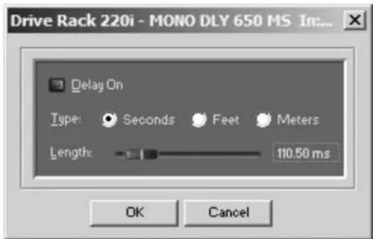
Delay On/Off
Turns the delay on and off.
Length
Sets the amount of delay time.
Units - Seconds, Feet or Meters
Selects the unit of measurement for the delay.
3.15 - Output
The output section 220i DriveRack provide the user with the ability to control output levels of the unit and adjust phase compensation of loudspeakers within the signal path. The output level control is located in the signal path before the compressor/limiters; this means that the compressor/limiter directly affects the output level. The parameters for the Phase Compensation effect are as follows and are user adjustable.

Polarity/Phase On/Off
This parameter is used to turn the selected output phase and polarity on parameters on or off. When off, the phase is 0^ and polarity is positive.
Polarity Positive or Negative
This section is used to select either the Positive or Negative polarity.
Phase 0 to 180
This parameter sets the amount of phase within the selected output path. The phase is referenced to the uppermost frequency within the band.
3.16 - Subharmonic Synthesizer
The Subharmonic Synthesizer module has been specifically optimized to enhance Bass audio material for use in a variety of professional applications, including nightclub and dance DJ mixing, theatre and film sound, music recording, live music performance and broadcasting.
The Subharmonic Synthesizer module's two separate bands of subharmonic synthesis provide the best combination of smoothness and control, and the independent low frequency boost circuit is designed to get the most out of high-performance low frequency speaker systems.
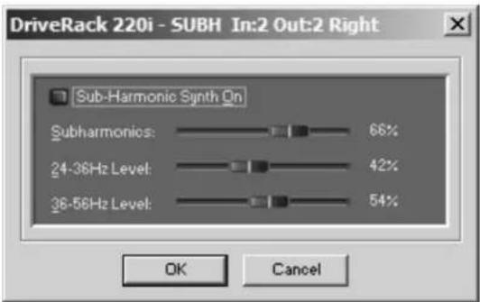
Sub-Harmonic Synth - On/Off
Turns the Subharmonic Synth module on and off.
Sub-Harmonics Synth - 0 to 100%
This parameter sets the overall level of the Subharmonic Synthesizer.
24-36Hz and 36-56Hz (Subharmonic Synthesis) Level - 0 to 100%
These controls individually let you customize the amount of the respective synthesized frequencies to be added in, tuning the ultimate bass response of your system to taste. For example, if the sound is too woofy or growly, try turning down the 36Hz-56Hz level. If your woofers are bottoming out (making a ticking, popping sound), try turning down the 24Hz-36Hz level. You may find that a setting produces fine results in one room, but produces too much boominess in another. If this occurs, adjust the controls as needed, (e.g., increase one or the other of the band levels). Experimentation will pay off with smooth, full, deeply extended bass. Remember, you are not selecting a frequency. You are controlling the overall level of each band.
Utilities
Program List
Zone Control
Front Panel Lockout

The Utility section of the DriveRack 220i gives you the ability to perform several key operational functions including: custom Program List creation, Zone Controller settings, and front panel lockout mode selection. Use this section of the manual to make yourself familiar with all aspects of the Utility menu of the DriveRack system.
4.1 - Program List/Program Change
The 220i allows you to set the unit to either scroll through programs in a sequential manner, or create custom program lists from within the Utility menu. This list makes it convenient for restricting access to a small list of programs. The procedure for setting up the program list is as follows.
Open the Utility menu by clicking on Edit on the Menu Bar, and selecting Utilities.
To create a custom Program list first, select the desired list size by using the up and down arrows to the right of the Program List Size indicator.

Select the programs in the list by clicking on one of the programs then use the up and down arrows at the bottom of the window to select which program from the user program table you want.
4.2 - ZC Setup
This feature gives you the ability to create a custom interface for the end user and program that interface for either program selection or output level and mute.
The Zone Controllers offer additional utility to the DriveRack® 220i. They allow real-time adjustment of output levels, mutes and program changes from simple wall panel interfaces. On the 220i, a maximum number of six Zone Controllers may be used and they may be nested, in other words, one controller may be used for a single zone and then another controller may be used for the entire venue or system. With a maximum distance of up to 1000 ft. on CAT5 cable with RJ-45 connectors, the Zone Controllers offer an easy to program and use remote control surface.
Programming
To be programmed, each Zone Controller must have its identification set using the DIP switches on the rear of the panel. The Zone Controllers are programmed from the Utility menu in the GUI. The Zone Controllers are programmed from the Utility menu in the GUI. The ZC-3 and ZC-4 allow program selection from either a wall panel, or contact closures. The diagrams on the following page show screen shots from the GUI, a ZC-3 being programmed with the selected programs and the panel that is assigned and a ZC-4 being programmed with up to four contact switches and the program that each of these combinations of switches will load.
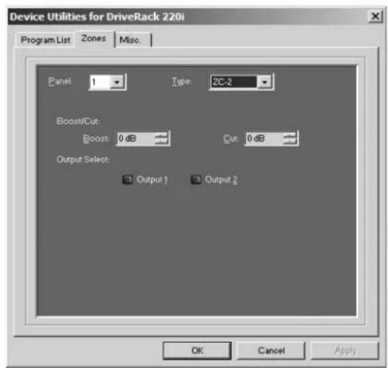
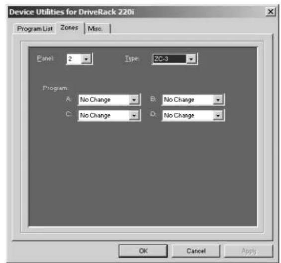
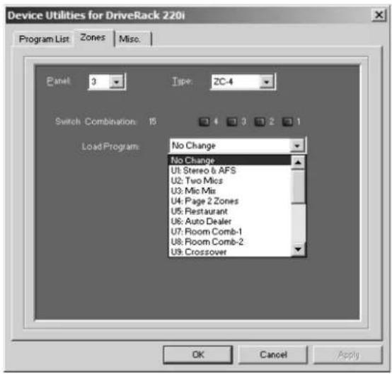
4.3 - Front Panel Lockout
The Utility menu of the 220i also offers the option of performing a front panel lockout. This is the perfect security deterrent for unwanted editing. Open the utility menu by selecting Edit on the Menu Bar and then clicking on Utilities. Select the tab labeled Misc. and select Front Panel Lockout Mode. You can then choose between a complete Front Panel Lockout, Front Panel Lockout with Filter Clearing, or Unlocked.

APPLICATION Guide

natural_image
Front view of a DriveRack 220i System Processor MR-475 CPU interface with visible drive, ports, and display (no readable text beyond branding)This Application guide section is provided to offer suggested installation applications of the DriveRack ^® units that will allow you to optimize peak performance of the units. Note that the four included applications represent the extensive flexibility of the DriveRack ^® units. These applications can be used verbatim, or as sample reference guide templates for designing countless audio applications.
5.1 - Mic Processing/Mixing
Hardware
- Connect the outputs of the microphones to the inputs of the DriveRack.
- Connect the outputs of the DriveRack to the mixer.
- Making sure that all outputs are muted, apply power to the mixer and amplifiers.
- Make connections between the Zone Controllers and the 220i if applicable.
Software
- Select Program 3 - Mic Mix as a template.
- Load the program by from the front panel or from the DriveWare GUI.
- Adjust the individual parameters for the system by selecting the Processing Module from the GUI interface.
- Using the Utility Menu, select the ID for the Zone Controller if applicable.

flowchart
graph TD
    A["Speaker"] --> B["Device"]
    B --> C["Grid"]
    C --> D["Grid Filter"]
    D --> E["Output"]
    style A fill:#f9f,stroke:#333
    style B fill:#ccf,stroke:#333
    style C fill:#cfc,stroke:#333
    style D fill:#fcc,stroke:#333
    note right of B: Provides:
    Mic Pre
    EQ
    Feedback Suppression
    Mixing
    Hignpass Filtering
    Compression
    Gating
Provides:
Mic Pre
EQ
Feedback Suppression
Mixing
Hignpass Filtering
Compression
Gating
5.2 - Stereo/Dual Mono System Processing
Hardware
- Connect the outputs of the mixer to the inputs of the DriveRack.
- Connect the outputs of the DriveRack to the inputs of the amplifier.
- Making sure that all outputs are muted, apply power to the mixer and amplifiers.
Software
- Select Program 1 - Stereo & AFS.
- Load the program by pressing the Program Up and Down buttons on the front panel, or from the DriveWare GUI.
- Adjust the individual parameters for the system by selecting the Processing Modules from the DriveWare GUI.

flowchart
graph TD
    A["Audio Unit 1"] -->|Provides: EQ\nFeedback Suppression\nBandpass Filtering\nLimiting\nDelay\nCompression| C["Central Processing Unit"]
    B["Audio Unit 2"] -->|Provides: EQ\nFeedback Suppression\nBandpass Filtering\nLimiting\nDelay\nCompression| C
    C --> D["Output Display"]
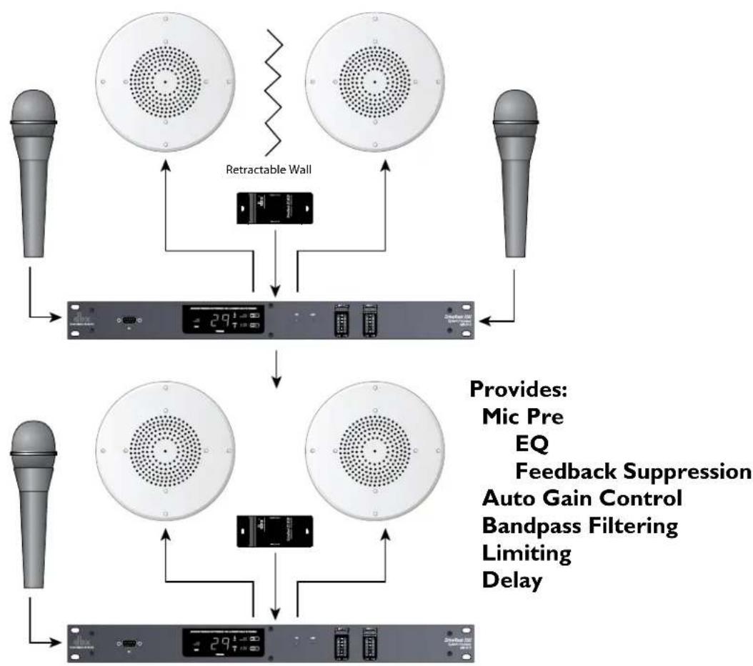
5.3 - Room Combining
Hardware
-
Connect the audio source to the inputs of the DriveRack.
-
Connect the outputs of the DriveRack to the amplifier.
-
Making sure that all outputs are muted, apply power to the mixer and amplifiers.
-
Make connections between the ZC-4 and the DriveRack. Make connections between the contact closure and the ZC-4.
Software
-
Select Program 7 - Room Combine 1.
-
Load the program from the front panel or from the DriveWare GUI.
-
Using the Utility menu, select the ID for the ZC-4 and program the ZC-4 with switch position 0 being Program 7 and switch position 1 being Program 8.
flowchart
graph TD
    A["Microphones"] --> B["Retractable Wall"]
    B --> C["Digital Display"]
    D["Microphones"] --> E["Retractable Wall"]
    E --> F["Retractable Wall"]
    G["Microphones"] --> H["Retractable Wall"]
    H --> I["Retractable Wall"]
    J["Microphones"] --> K["Retractable Wall"]
    K --> L["Retractable Wall"]
    M["Microphones"] --> N["Retractable Wall"]
    N --> O["Retractable Wall"]
    P["Microphones"] --> Q["Retractable Wall"]
    Q --> R["Retractable Wall"]
    S["Microphones"] --> T["Retractable Wall"]
    T --> U["Retractable Wall"]
    V["Microphones"] --> W["Retractable Wall"]
    W --> X["Retractable Wall"]
    Y["Microphones"] --> Z["Retractable Wall"]
    Z --> AA["Retractable Wall"]
    AB["Microphones"] --> AC["Retractable Wall"]
    AC --> AD["Retractable Wall"]
    AE["Microphones"] --> AF["Retractable Wall"]
    AF --> AG["Retractable Wall"]
    AH["Microphones"] --> AI["Retractable Wall"]
    AI --> AJ["Retractable Wall"]
    AK["Microphones"] --> AL["Retractable Wall"]
    AL --> AM["Retractable Wall"]
    AN["Microphones"] --> AO["Retractable Wall"]
    AO --> AP["Retractable Wall"]
    AQ["Microphones"] --> AR["Retractable Wall"]
    AR --> AS["Retractable Wall"]
    AT["Microphones"] --> AU["Retractable Wall"]
    AU --> AV["Retractable Wall"]
    AW["Microphones"] --> AX["Retractable Wall"]
    AX --> AY["Retractable Wall"]
    AZ["Microphones"] --> BA["Retractable Wall"]
    BA --> BB["Retractable Wall"]
    BC["Microphones"] --> BD["Retractable Wall"]
    BD --> BE["Retractable Wall"]
    BF["Microphones"] --> BG["Retractable Wall"]
    BH["Microphones"] --> BI["Retractable Wall"]
    BI --> BJ["Retractable Wall"]
    BK["Microphones"] --> BL["Retractable Wall"]
    BL --> BM["Retractable Wall"]
    BN["Microphones"] --> BO["Retractable Wall"]
    BO --> BP["Retractable Wall"]
    BQ["Retractable Wall"] --> BR["Digital Display"]
5.4 - BGM/Paging
Hardware
- Connect the audio source to CH 2 of the DriveRack 220i.
- Connect the outputs of the DriveRack to the amplifier.
- Making sure that all outputs are muted, apply power to the mixer and amplifiers.
- Make connections between the Zone Controllers and the 220i if applicable.
Software
- Select Program 5 - Restaurant.
- Load the program from either the front panel of the DriveWare GUI.
- Adjust the individual parameters for the system by selecting and editing the Processing Modules from the DriveWare GUI.
- Using the utility menu select the ID for the Zone Controller and program the boost and cut amounts.

flowchart
graph TD
    A["Speaker"] --> B["291 MHz"]
    C["BGM / Paging"] --> D["Speaker"]
    E["Radio"] --> F["Signal"]
    G["Audio Input"] --> H["Signal"]
    I["Control Panel"] --> J["Output"]
    K["Provides: Mic Pre, EQ, Feedback Suppression, Auto Gain control, Band Pass Filtering, Limiting"] --> L["Display"]

natural_image
Front view of a DriveRack 220i system processor with visible I/O port, status LEDs, and control buttons (no readable text beyond branding)A.1 - Factory Reset/Flash Update
In the event that a reset is required, the DriveRack ^® 220i offers you the option of performing a “Soft” or “Hard” reset. The Soft Reset resets all operating parameters except user programs. The Hard Reset Procedure will reset all programmable information back to the factory defaults.
Factory ("Hard") Reset
- Press and hold the PROGRAM UP button on power-up until the following message appears in the 7-Seg Display: Hd
- Pressing the LOAD button will start a Factory Reset (All User Programs will become copies of the Factory Programs, all Utility settings will be defaulted, and all Security settings will be defaulted) Pressing any other button will abort the Factory Reset sequence and the unit will reset normally.
Factory ("Soft") Reset.
- Press and Hold the PROGRAM DOWN button on power-up until the following message appears in the 7-Scg Display: 5t
- Pressing the LOAD button will start a System Reset (All Utility settings will be defaulted.) Pressing any other button will abort the System Reset sequence and the unit will reset normally.
Flash Update
To flash update the firmware version of the DriveRack 220i the unit needs to be put into Flash Update Receive mode. This is done by holding the LOAD button while connecting power to the unit. Once in Flash Update Receive mode it is ready to receive the new firmware.
A.2 - Specifications
Analog Inputs:
Number of Inputs: (2) Switchable line or mic inputs
Connectors: Female XLR line inputs and Euroblock
Type: Electronically balanced/RF filtered
Impedance: > 50kΩ
Max input line level: +20dBu
CMRR: > 40dB, typically >55db @ 1kHz
Mic Pre gain: 30 to 60dB
Mic EIN: < 118dB, 22Hz-22kHz, 150Ω
Mic Phantom Power: 15V
Analog Outputs:
Number of Outputs: (2)
Connectors: Male XLR and Euroblock
Type: Electronically balanced, RF filtered
Impedance: 120 Ω balanced, 60Ω unbalanced
Max Output Level: +20dBu
A/D Performance:
Type: dbx Type IV ^TM conversion system
Dynamic Range line: >113 dB A-weighted, >110 dB unweighted
Type IV dynamic range: >119 dB, A-weighted, 22kHz BW
117 dB, unweighted, 22kHz BW
Sample Rate: 48kHz
D/A Performance:
Dynamic Range: 112 dB A-weighted, 109dB unweighted
System Performance:
Dynamic Range: >110 dB A-weighted, >107dB unweighted,
THD+N: 0.003% typical at +4dBu, 1kHz, 0dB gain
Frequency Response: 20Hz - 20kHz, +/- 0.5dB
Interchannel Crosstalk: >110dB, 120dB typical
Crosstalk input to output: >80dB
Propagation Delay: 0.6 msec
Operating voltage: 100 VAC, 50/60Hz, 120 VAC, 60Hz, 230VAC 50/60Hz
Power Requirements: 12 Watts
Physical:
Weight: 5.5 lbs.(2.5 kg) Shipping weight 7 lbs. (3.18 kg)
Dimensions: 1.75" H x 5.75" D x 19" W
A.3 - Program List
Factory Program List
- Stereo & AFS - Designed for Stereo systems.
- Two Mics - Processing for two separate microphones.
- Mic Mix - Processing and mixing two microphones together.
- Page 2 Zones - With a microphone in ch. 1 and music in ch. 2 this will send both music and page announcements to both outputs.
- Restaurant - With a setup similar to #4, the music is sent to both outputs, but the paging only occurs in output 2 (Lobby).
- Auto Dealer - Similar to programs #4 and #5, but the music is only sent to the output #2 (Showroom), while paging is sent to both outputs.
- Room Comb-1 - This program is the first of two that allows room combining. In this program the rooms are separate.
- Room Comb-2 - This program is the second of two programs that provide room combining. This program combines the two rooms with inputs from either room being sent to both rooms.
- Crossover - This program uses input 1 as the source for a bi-amp crossover at 100 Hz.
- Mix & XOver - Like program #9, this program provides crossover functions, with the addition of mixing together inputs 1 and 2.
Programs 11-20 are duplicates of these first 10.
A.4 - Block Diagram

flowchart
graph TD
    A["Input"] --> B["Type IV Tin"]
    B --> C["DSP"]
    C --> D["Micro Processor"]
    D --> E["Logic"]
    E --> F["Output"]
    G["RF Filter"] --> H["Power Down relay bypass"]
    H --> I["Power Down relay bypass"]
    I --> J["RF Filter"]
    J --> K["Output"]
    L["DCAM"] --> M["Front RS 232"]
    M --> N["Micro Processor"]
    N --> O["Output"]
    P["DCAM"] --> Q["Front RS 232"]
    Q --> R["Micro Processor"]
    R --> S["Output"]
    T["DCAM"] --> U["Front RS 232"]
    U --> V["Micro Processor"]
    V --> W["Output"]
    X["DCAM"] --> Y["Front RS 232"]
    Y --> Z["Micro Processor"]
    Z --> AA["Output"]
    AB["DCAM"] --> AC["Front RS 232"]
    AC --> AD["Micro Processor"]
    AD --> AE["Output"]
    AF["DCAM"] --> AG["Front RS 232"]
    AG --> AH["Micro Processor"]
    AH --> AI["Output"]
    AJ["DCAM"] --> AK["Front RS 232"]
    AK --> AL["Micro Processor"]
    AL --> AM["Output"]
    AN["DCAM"] --> AO["Front RS 232"]
    AO --> AP["Micro Processor"]
    AP --> AQ["Output"]
    AR["DCAM"] --> AS["Front RS 232"]
    AS --> AT["Micro Processor"]
    AT --> AU["Output"]
    AV["DCAM"] --> AW["Front RS 232"]
    AW --> AX["Micro Processor"]
    AX --> AY["Output"]
    AZ["DCAM"] --> BA["Front RS 232"]
    BA --> BB["Micro Processor"]
    BB --> BC["Output"]
    BD["DCAM"] --> BE["Front RS 232"]
    BE --> BF["Micro Processor"]
    BF --> BG["Output"]
    BH["DCAM"] --> BI["Front RS 232"]
    BI --> BJ["Micro Processor"]
    BJ --> BK["Output"]
    BL["DCAM"] --> BM["Front RS 232"]
    BM --> BN["Micro Processor"]
    BN --> BO["Output"]
    BP["DCAM"] --> BQ["Front RS 232"]
    BQ --> BR["Micro Processor"]
    BR --> BS["Output"]
    BT["DCAM"] --> BU["Front RS 232"]
    BU --> BV["Micro Processor"]
    BV --> BW["Output"]
    BX["DCAM"] --> BYD["Front RS 232"]
    BYD --> BZ["Micro Processor"]
    BZ --> CA["Output"]
    CB["DCAM"] --> CC["Front RS 232"]
    CC --> CD["Micro Processor"]
    CD --> CE["Output"]
    CF["DCAM"] --> DG["Front RS 232"]
    DG --> DH["Micro Processor"]
    DH --> DI["Output"]
    DJ["DCAM"] --> DK["Front RS 232"]
    DK --> DL["Micro Processor"]
    DL --> DJ["Output"]
    DKT["DCAM"] --> DE["DSP"]
    DE --> DF["DSP"]
    DF --> DG
    DG --> DGTP["DSP"]
A.5 - Gain and Relay Jumpers
CAUTION: These servicing instructions are for use by qualified service personnel only. To reduce the risk of electric shock, do not perform any servicing other than that contained in the operating instructions unless you are qualified to do so. Refer all servicing to qualified service personnel. Disconnect mains power before servicing.

The 220i DriveRack gives you the option of changing the input gain level settings. There are 2 hardware configurable gain settings. They are: +4 dBu, -10 dBV. For these cases, use the following procedure to change the gain level settings. Please be advised however, that once the gain level has been changed from the factory settings, the output meters will no longer be calibrated correctly.
You can configure the unit to pass audio when it is not powered up. Please refer to the information below. You can also configure the unit to not pass audio when the power is off (Relay Bypass); the normal mode is Relay bypass.
To change the gain level or relay jumpers move the jumpers to the desired settings.
- First, make sure that the unit has been shut off and unplugged prior to opening the unit.
- Ground yourself prior to opening the 220i chassis to prevent ESD damage.
- Open the chassis by removing 4 screws on each side of the chassis, as well as the top center allen screw located on the front panel.
- Locate the jumper block shown in the illustration below:
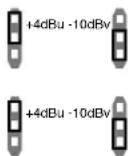
Input/Output □ Jumpers Levels

Bypass Jumpers
Jumper Locations:
- Input and Output jumpers are located at P4, P8, and P6 for Channel 1 and at P5, P9 and P13 for Channel 2.
- Bypass Jumpers are located at P7 for Channel 1 and P12 for Channel 2.
NOTE: There are two jumper blocks per input and one jumper block per output
A.6 - Tips, Tricks and Troubleshooting
Speaker Tunings
Various “Speaker Tunings” are available for some of the different DriveRack units; on the DriveRack 480 units speaker tunings can be downloaded from the website, whereas on the DriveRack 260 the speaker tunings are found in the Wizard function. Since they are not all available for the same platforms there is a mechanism to replicate these tunings from one DriveRack type to the next. Open the platform that has the speaker tuning. Open a second DriveWare window and insert the DriveRack unit that will be your final platform; for example if you want to create JBL AE tunings for the DriveRack 480 series, open a DriveWare window with a 260 in it, and one with the 480. Download or use the Wizard function to get the correct tunings on the first DriveRack unit. Since the AE tunings are available for the DriveRack 260, you would go through the Wizard function to create the appropriate tuning for the 260. Create the correct configuration for the destination unit and then Copy and Paste parameters where available and otherwise copy the parameters from one unit to the next. For our example you would create the correct configuration for the DriveRack 480 and then Copy and Paste parameters that can be pasted, and manually copy and enter the parameters from the 260 into the 480. Since the DriveRack devices use the same algorithms there will be very little difference between them.
DriveWare Communication
If you are having difficulty connecting your DriveRack device with your computer, there are a few things that can be done to find the source of the problem and correct it.
HotSync Manager
If you use a Palm ^® computing device, the HotSync Manager generally takes control of your COM port; you must disable your HotSync Manager to get DriveWare to connect to your DriveRack unit. This can be done by right clicking on the HotSync Manager icon down on the toolbar. You can then select Exit; this will allow DriveWare to use your COM port. The HotSync Manager will return when you reboot your computer.
COM port Selection
If you are using anything other than your first COM port, you will need to go into Preferences and select the correct COM port. Preferences are found under File on the DriveWare Menu Bar.
A.7 - Zone Controller Wiring and Install
Zone Controller Wiring
The DriveRack Zone Controllers, (ZC-1, ZC-2, ZC-3, ZC-4) can be wired serially or in parallel. To wire in series each Zone Controller must have an identification or zone number chosen using the DIP switches on the side of the controller (see diagram A). Each controller must have a unique number chosen although there may be multiple Zone Controllers controlling a single zone, or a single Zone Controller that controls multiple outputs. The Zone Controllers can then be wired together and connected to the DriveRack (see diagram B).
The Zone Controllers may also be wired in parallel with the use of the ZC-BOB. To wire in parallel (home run cabling), each controller must have a unique identification or number chosen using the DIP switches on the rear of the panel (see diagram A). To wire in parallel, each controller must be wired into a port of the ZC-BOB with a connecting wire going to the DriveRack (see diagram C).
Zone Controller Installation
The installation of the Zone Controllers MUST be accomplished with the use of cable which is rated VW-1 or higher. Common NEC designations which meet this rating include: CMP, CMR, CMG, CM and CMX.
ZC-1
The ZC-1 is a programmable zone controller that allows volume level control from a wall panel.
ZC-2
The ZC-2 is a programmable zone controller that allows volume level and mute control from a wall panel.
ZC-3
The ZC-3 allows wall panel program selection for the 220i.
ZC-4
The ZC-4 provides contact closure program selection for room combining or fire safety applications.
ZC-BOB
The ZC-BOB allows parallel or home run cabling of the Zone Controllers.
Diagram A

Diagram B
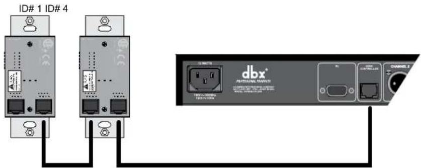
Diagram C

flowchart
graph TD
    A["ID# 3"] --> D["DriveRack ZC-808"]
    B["ID# 6"] --> D
    D --> C["DBX Network"]
    C --> E["DBX Channel 1"]
Zone Controller Cable Specifications:
Cat 5 Cable / 4-Twisted Pairs of 24 AWG Wire / 568B Standard

other
| RJ-45 (8-Position) | White / Orange | Orange | White / Green | Blue | White / Blue | Green | White / Brown | Brown | |---|---|---|---|---|---|---|---|---| | 1 | 1 → Voltage Reference | 2 ←→ Controller 1 ←→ | 3 ←→ Controller 2 ←→ | 4 ←→ Controller 3 ←→ | 5 ←→ Controller 4 ←→ | 6 ←→ Controller 5 ←→ | 7 ←→ Controller 6 ←→ | 8 → Ground | Legend: ON (ON), 23456 (ON), 23456 (CN), 23456 (CN), 23456 (ON)Diagram A
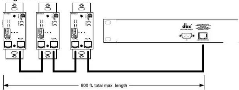
Diagram B

Diagram C

dbx®
by HARMAN
8760 South Sandy Parkway • Sandy, Utah 84070
Phone: (801) 568-7660 • Fax (801) 568-7662
Int'l Fax: (801) 568-7583
Questions or comments?
E-mail us at: customer@dbxpro.com or visit our
website at: www.dbxpro.com or
www.driverack.com
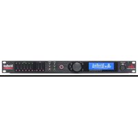
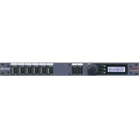
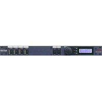
- IMPORTANT SAFETY INSTRUCTIONS
- SAFETY INSTRUCTIONS
- WARNING FOR YOUR PROTECTION READ THE FOLLOWING:
- ELECTROMAGNETIC COMPATIBILITY
- U.K. MAINS PLUG WARNING
- NEVER UNDER ANY CIRCUMSTANCES SHOULD YOU INSERT A DAMAGED OR CUT MAINS PLUG INTO A 13 AMP POWER SOCKET.
- DECLARATION OF CONFORMITY
- Introduction
- Getting Started
- Software Operation
- Detailed Parameters
- Utilities
- Application Guide
- Appendix
- INTRO
- - Defining the 220i System
- 220i features:
- - Service Contact Info
- - Warranty
- GetInG
- StArteD
- I.I - Rear Panel
- IEC Power Cord Receptacle
- PC Connection
- Zone Control Input (RJ-45 connector type)
- Inputs 1-2
- Outputs 1-2
- Signal/Clip LED
- Mic Gain Control
- Line/Mic Selector
- - Front Panel
- Load Button
- Program Display
- Program Up and Down (Filter Clear Ch1 and Ch2)
- PC LED
- CLIP LED
- Input Meters
- Threshold Meters
- Output Meters
- - Connections
- I.4 - PC GUI Installation
- Minimum System Requirements
- Installation
- SoFtWAre oPerAtlon
- - DriveRack 220i Philosophy
- Programs
- Utilities and Mutes
- - PC Connection
- - Views
- - Configuration
- - Editing
- - Copy and Paste
- - Meters and Mutes
- - Loading
- - Storing
- - Importing and Exporting
- - Utilities
- - Online/Offline
- - Preferences
- - Input Routing
- Input I Level -Inf to 20dB
- Input 2 Level -Inf to 20dB
- Level Left or Right Inf to 20dB
- - Pre-Matrix EQ
- GEQ
- EQ On/Off
- Flatten/Restore
- Frequency (F) 31.5Hz to 16.0kHz
- Gain (G) -12 to +12 dB
- PEQ
- Flat Set/Undo
- Band I Frequency 20 to 20kHz (Low Shelf)
- Slope I 3-12dB/Octave
- Level 1 -12 to 12 dB
- Band (2-8) Frequency 20 to 20k
- Q (2-8) 0.105 to 16.0
- Level (2-8) -12 to 12 dB
- Band 9 Frequency 20 to 20k (High Shelf)
- Slope 9 3-12dB/Octave
- Level 9 -12 to 12 dB
- - Advanced Feedback Suppression
- AFS On/Off
- Clear Live/All
- Mode - Live or Fixed
- Type - Speech, Low Music, Medium Music and High Music
- Total Number of Filters I-12
- Number Fixed - 0-12
- Live Filter Lift (On/Off)
- Lift After - 5 sec to 60 min
- Virtual Highpass 0.00-410.1Hz
- Sensitivity -20-+20dB
- - Automatic Gain Control (AGC)
- AGC: On/Off
- Target: -20 to 20 dB
- Gain: I to 20dB
- Window: I to 10dB
- Low Threshold: -60 to -30dB
- Attack: 0.20 to 5 Seconds
- Release: 30.0 to 1 dB/Second
- - De-Esser
- De-Esser On/Off
- Freq. 800 Hz to 8.00 kHz
- Amount 0 to 100%
- Type HP or BP
- Width
- - Ducker
- Ducker On/Off
- Threshold -40 to +20dBu
- Amount -0 to 6dB
- Attack 0.1 m Sec to 200 m Sec
- Hold 0 to 500 m Sec
- Release 360 dB / Sec to 5 dB / Sec
- - Compressor
- Compressor On/Off
- OverEasy (O) Off to 10
- Threshold (T) -40 to +20dBu
- Ratio (R) 1.0 to Inf:1
- Gain (G) -20 to +20 dB
- Auto On/Off
- Gate On/Off
- Threshold -50 to 20 dBu
- Ratio 1:1.0 to 1:15
- Attack 0.1 to 200 m Sec
- Release 360 to 5 dB
- Max ATT 0 to Inf. dB
- - Notch Filters
- Notch On/Off
- Frequency (1 to 6) 20 to 20K
- Gain -36 to 6 dB
- Q 16 to 128
- - Matrix Mixer
- Input A Level -Inf to 20dB
- Input B Level -Inf to 20dB
- Output I Level -Inf to 20dB
- Output 2 Level -Inf to 20dB
- - Post-Matrix PEQ
- PEQ On/Off
- Type
- Band (I-4) Frequency 20Hz to 20kHz
- Level (1-4) -12dB to 12dB
- Q (I-4) 0.20 to 16 dB
- - Bandpass Filter
- Highpass Out to 20kHz
- Lowpass Out to 20Hz
- - Limiter
- Limiter On/Off
- Auto On/Off/
- Attack .01 to 200 m Sec (per band or global)
- Hold 0 to 500 m Sec (per band or global)
- Release 360 to 5 dB / Sec (per band or global)
- PeakStop+TM On/Off and I-6
- Overshoot 1-6
- - Delay
- Delay On/Off
- Length
- Units - Seconds, Feet or Meters
- - Output
- Polarity/Phase On/Off
- Polarity Positive or Negative
- Phase 0 to 180
- - Subharmonic Synthesizer
- Sub-Harmonic Synth - On/Off
- Sub-Harmonics Synth - 0 to 100%
- 24-36Hz and 36-56Hz (Subharmonic Synthesis) Level - 0 to 100%
- Program List
- Zone Control
- Front Panel Lockout
- - Program List/Program Change
- - ZC Setup
- Programming
- - Front Panel Lockout
- - Mic Processing/Mixing
- Hardware
- Software
- - Stereo/Dual Mono System Processing
- - Room Combining
- - BGM/Paging
- A.1 - Factory Reset/Flash Update
- Factory ("Hard") Reset
- Factory ("Soft") Reset.
- Flash Update
- A.2 - Specifications
- Analog Inputs:
- Analog Outputs:
- A/D Performance:
- D/A Performance:
- System Performance:
- Physical:
- A.3 - Program List
- Factory Program List
- A.4 - Block Diagram
- A.5 - Gain and Relay Jumpers
- Input/Output □ Jumpers Levels
- Bypass Jumpers
- Jumper Locations:
- A.6 - Tips, Tricks and Troubleshooting
- Speaker Tunings
- DriveWare Communication
- HotSync Manager
- COM port Selection
- A.7 - Zone Controller Wiring and Install
- Zone Controller Wiring
- Zone Controller Installation
- ZC-1
- ZC-2
- ZC-3
- ZC-4
- ZC-BOB
- dbx®
- by HARMAN
Brand : DBX
Model : DriveRack 220i
Category : Audio processor