
OBM-U318K - Monitor Postium - Free user manual and instructions
Find the device manual for free OBM-U318K Postium in PDF.


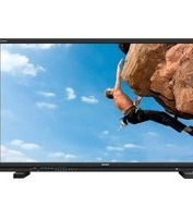
| Product Type | Professional Video 8K Monitor |
| Brand | Postium |
| Model | OBM-U318K |
| Display Size | 32" LCD |
| Resolution | 3840 x 2160 (16:9) |
| Pixel Pitch | 0.1845 mm |
| Color Depth | 1.073B Colors, 10 Bit |
| Viewing Angle | 178° (H) / 178° (V) |
| White Luminance | 1000 cd/m² |
| Contrast Ratio | 1500:1 |
| Inputs | 4 x BNC (12G/6G/3G/HD-SDI), 1 x HDMI 2.0, 2 x SFP |
| Outputs | 4 x BNC (12G/6G/3G/HD Active Loop Output) |
| Audio | 2 x Speaker Out (Stereo), 1 x Headphone Jack (Front) |
| Power Requirements | AC 100-230V, 50/60Hz or DC 24V |
| Power Consumption | TBD (Refer to manual) |
| Operating Temperature | 0°C to 40°C (32°F to 104°F) |
| Operating Humidity | 20% to 80% RH |
| Weight (Main Body) | 14.8 kg (32.62 lbs) |
| Dimensions (W x H x D) with Stand | 762 x 512 x 190 mm (30 x 20.15 x 7.48 inch) |
| Key Features | 8K/4K support, HDR (PQ, HLG, S-Log3), Wide Color Gamut (BT.2020, DCI-P3, etc.), 3D LUT, Waveform/VectorScope, Focus Assist, False Color, Remote Control via Ethernet/RS-422, GPI |
| Maintenance | Clean with mild, neutral detergent; do not use abrasive cleaners |
| Safety Precautions | Use specified voltage; avoid liquid contact; unplug if not used; keep ventilated; do not attempt self-service |
| Spare Parts | Use only manufacturer-specified replacement parts |
Frequently Asked Questions - OBM-U318K Postium
User questions about OBM-U318K Postium
0 question about this device. Answer the ones you know or ask your own.
Ask a new question about this device
Download the instructions for your Monitor in PDF format for free! Find your manual OBM-U318K - Postium and take your electronic device back in hand. On this page are published all the documents necessary for the use of your device. OBM-U318K by Postium.
USER MANUAL OBM-U318K Postium
Professional Video 8K Monitor

Operational Instructions
OBM-U178K
OBM-U248K
OBM-U278K
OBM-U318K

www.postium.com
Table of Contents
- Precaution 3
- Main Features 5
- Location and Function of Parts and Controls
Front Panel 6
Rear Panel 8 - Using the Menu 10
- Adjustment Using the Menu 11
- OSD Menu Operations
Status Menu 14
Color Temp/Color Space/Gamma Menu----15
Camera Assist Menu 18
User Configuration Menu 18
Remote Menu 23
Security Menu 26 - Scan Mode Image 27
- Connecting the SDI Signals 28
- Available Signal Formats 29
- Key Functions 31
- Product Specifications 39
1. Precaution
Always use set voltage.
AC 100 \~ 230V, 50/60Hz
DC 24V(OBM-U178K, OBM-U248K, OBM-U278K, OBM-U318K)
All these instructions should be read and understood before operating the unit.
If liquid is spilled on or impacts this product, please disconnect the product immediately and seek professional help before continued use.
Unplug the product from the wall outlet if it is not to be used for several days or more.
Keep the product in a well-ventilated place to prevent overheating.
Do not install the product near any heat-generating equipment. Also, keep the product out of direct sunlight or dusty areas.
Protect the power cord from being walked on or pinched particularly at plugs, convenience receptacles, and the point where they exit from the apparatus.
When using other DC 24V(OBM-U178K, OBM-U248K, OBM-U278K, OBM-U318K) adapters instead of the standard adapter provided by the manufacturer, please check the proper load capacity or current capacity and use an adapter with stable voltage.
Do not overload AC outlets or extension cords. Overloading can cause fire or electric shock.
A very small proportion of pixels may be stuck, either always off (black), always on (red, green, or blue), or flashing. In addition, over a long period of use, because of the physical characteristics of the liquid crystal display, such stuck pixels may appear spontaneously. These problems are not a malfunction.
If a fixed picture such as a frame of a divided picture or time code, or a still picture is displayed for a long time, an image may remain on the screen and be superimposed as a ghosting image.
The permanent burn-in may occur for LCD panel if still images are displayed in the same position on the screen continuously, or repeatedly over extended periods.
To reduce the risk of burn-in,
a. Turn off the character displays.
b. Turn off the power when not in use.
c. Turn off the power if the monitor is not to be used for a prolonged period of time.
Do not attempt to service the product yourself. Removing covers can expose you to high voltage and other dangerous conditions. Request a qualified service person to perform servicing.
When the product needs replacement parts, make sure that the service person uses replacement parts specified by the manufacturer, or those with the same characteristics and performance as the original parts. Use of unauthorized parts may result in fire, electric shock and/or other danger.
Only clean the product with a noncommercial, mild and neutral detergent.
Do not throw away the carton and packing materials. When transporting the product, make use of its original packaging for safer carriage.
FCC (Federal Communications Commission)
This equipment has been tested and found to comply with the limits for class A digital device, pursuant to part 15 of the FCC Rules. These limits are designed to provide reasonable protection against harmful interference when the equipment is operated in a commercial environment. This equipment generates, uses, and can radiate radio frequency energy, and if not installed and used in accordance with the instruction manual, may cause harmful interference to radio communications. Operation of this equipment in a residential area is likely to cause harmful interference in which case the user will be required to correct the interference at his own expense.
Warning!!: Changes or modifications not expressly approved by the manufacturer could void the user's authority to operate the equipment.
Disposal of Old Electrical & Electronic Equipment
(Applicable in the European Union and other European countries with separate collection systems)
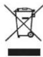
This symbol on the product or on its packing indicates that this product shall not be treated as household waste. Instead it shall be handed over to the applicable collection point for the recycling of electrical and electronic equipment. By ensuring this product is disposed of correctly, you will help prevent potential negative consequence for the environment and human health, which could otherwise be caused by inappropriate waste handling of this product. The recycling of materials will help to conserve natural resources.
2. Main Features
8K/4K professional monitor OBM-8K Series unit has the following features:
· 12G SDI Quad Link 8K / 12G-SDI Single Link 4K
· 6G-SDI Dual Link 2-S.I. 4K
· 3G-SDI Quad Link Square Division 4K / 3G-SDI Quad Link 2-Sample Interleave (2-S.I.) 4K
- Dual SFP Module Inputs (ST 2022-6 Support)
· HDMI 2.0 Input
- HDR(High Dynamic Range) Display supporting PQ (ST 2084), Hybrid Log Gamma, S-Log3
· Wide Color Gamut Supporting ITU-R BT.709, SMPTE-C, EBU, Native, DCI-P3, ITU-R BT.2020
- Internal color processing 72bit(24bitx3) + Native 33x33x33 30bit 3D-LUT
· 1.073 Billion Colors
- Gamut Error
- Black stretch
- Camera Log Conversion
- Custom 3D LUT file Import Through USB
· Gamma Selection (1.0 \~ 3.0)
· SDR EOTF - BT.1886 (Gamma 2.4)
· Color Temperature (3200K, 5500K, 6500K, 9300K, USER 1/2/3, D-CINEMA)
• Monitor Control via Ethernet, RS-422
· Image Division & Link Order Auto Detection
- Waveform, VectorScope (Wave + Vector)
- HDR Waveform
· Various Markers (EBU, 4:3, 16:9, 1.85:1, 2.35:1, Variable Custom)
- Zero Scan
· Time Code Display
- De-embedded 8\~16ch Audio Level Meter
- Internal Pattern Display for Color Test (Black \~ 100% White, Color Bar)
- Remote Control via GPI(RJ-45) Port
- False Color : Zebra, Color Pattern, ARRI
· Easy Firmware Update by USB
- System Data Copy
· H/V Delay
- Blue/Mono Only
- Focus Assist
· 3 Color TALLY Lamp
- HDR Auto Setting
- Aspect
- Freeze
3. Location and Function of Parts and Controls
Front Panel (OBM-U178K)
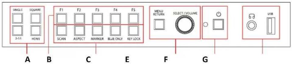
Front Panel (OBM-U248K/278K/318K)

A : Input select Buttons/Lamp
Press to monitor the signal input to each connector.
[SINGLE] Button/Lamp
- Press the button to select SDI input or SFP input for one channel.
- Mode changes in the order of [12G SDI-1], [12G SDI-2], [3G SDI-3], [3G SDI-4], [SFP]*.([SFP-1],[SFP-2]*)
*SFP input is set deactivated in the default setting. Change the menu setting to activate SFP input. MENU > User Configuration > [2/7] > SFP Enable > Enable
**Note
How to make a quick input change: When you push [SINGLE] button and the current input indicator is displayed, turn the [SELECT/VOLUME] knob to select another input and push the knob, then you can go to another input directly.
[2-S.I.] Button/Lamp
- Press the button to select 2-Sample Interleave SDI input signal through two or four SDI input connectors.
- Mode changes in the order of [Dual-Link 2-S.I.], [Quad-Link 2-S.I.].[Dual-Link 2-S.I.(SFP)*]
[SQUARE] Button/Lamp - Press the button to select [Quad-Link Square Division] mode.
[HDMI] Button/Lamp - Press the button to select HDMI input.
B : F1 \~ F5 Button/Lamp
Press to adjust or turn on/off the assigned function. The following functions are assigned at the factory.
[F1]: Color Temp
[F2]: Audio Level Meter
[F3]: Time Code
[F4]: Zebra & False Color
[F5]: Focus Assist
C : Function Button/Lamp
Press to adjust or turn/off each function.
[SCAN] Button - Press the button to adjust the scan mode. (Zero Scan, 1:1 Scan).
[ASPECT] Button
- Press the button to select the Aspect Ratio of the signal.
- Mode changes in the order of [16:9], [4:3], [2.35:1], [1.85:1], [15:9], [16:10], [AUTO].
[MARKER] Button - Press the button to activate and deactivate the Marker.
[BLUE ONLY] Button
- Press the button to activate and deactivate the Blue Only function.
- You may remove R(red) and G(green) from the input signal and display the screen only with B(blue) signal.
This function is convenient to adjust Chroma and Phase and to observe the signal noise. - The button may be pressed twice to change the screen to MONO mode.
(This mode uses only Luminance value.)
[KEY LOCK] Button- Press the button to lock all buttons except Power/Menu.
D : Rotary encoder
[BRIGHT] knob
Press this knob to display the adjustment screen and adjust the picture brightness. Press again to hide the adjustment screen. Turn the knob right to increase the brightness and turn left to decrease it.
[CONTRAST] knob
Press this knob to display the adjustment screen and adjust the picture contrast. Press again to hide the adjustment screen. Turn the knob right to increase the contrast and turn left to decrease it.
[CHROMA] knob
Press this knob to display the adjustment screen and adjust the color intensity. Press again to hide the adjustment screen. Turn the knob right to increase the color intensity and turn left to decrease it.
[APERTURE] knob
Press this knob to display the adjustment screen and adjust the picture sharpness. Press again to hide the adjustment screen. Turn the knob right to make the picture sharper and turn it left to make the picture softer.
**Note: If you push the knob for 2 seconds, the adjusted value returns to the default value.
E : Menu Operation Buttons
Displays or sets the on-screen menu.
[MENU/RETURN]
- Activates and deactivates the display of the Main Menu.
- When the on-screen menu is not displayed, if this button is pressed the main menu is displayed.
When the menu is displayed, press the button to return to the previous menu.
[SELECT/VOLUME] knob (Menu selection control)
- When the menu is displayed, turn the knob to select a menu item or a setting value, and then press the knob to confirm the setting.
- If this knob is pressed when the menu is not displayed, the adjustment screen of [VOLUME] is displayed to adjust the audio volume.
- Press this knob to change the modes in the order of [Focus Frequency], [Zebra Level], [Line Position], [Variable Marker] and adjust each mode's value.
[Focus Frequency]: When Focus Assist function is activated, this mode is displayed.
[Zebra Level]: When Zebra function is activated, this mode is displayed.
[Line Position]: When WFM/Vector function and Line Select function is activated, this mode is displayed.
[Variable Marker]: When Marker function is activated and Aspect Marker is set Variable, this mode is displayed.
F : (Standby) Switch and Indicator
- Press to turn the power on when this monitor is in standby mode. After being turned on, the monitor performs initialization and the indicator flashes in green.
- Press the switch again for a second to set the monitor in standby mode. Then, the indicator flashes in orange and then turns red. The indicator in orange means that the monitor goes into the standby mode.
When the indicator flashes in orange, this button doesn't work.
G : 📋 (headphone) Jack and USB Connector
Headphone Jack
- The audio signal which is selected using the input select button is output in stereo sound form speakers.
- When SDI signals are input, the audio signals of the channels selected with SDI Audio Setting in the User Configuration menu are output.
- When the headphone is connected to the jack, audio signals will not be output from speakres.
[USB] Connector
- To update CPU, GPU, FPGA program.
- To connect the monitor with the Color Calibration program provided by the manufacturer and perform the color calibration.
- To connect the monitor with the control program provided by the manufacturer and control functions remotely.
- To impot the custom 3D LUT file(*.cube,32^3, 33^3, 64^3 and 65^3).
Rear Panel (OBM-U178K / OBM-U248K / U278K / U318K)

A : SDI IN (SDI Input) connectors (BNC)
Input connectors for SDI signals. For details. Connecting the SDI Signals" (page 28).
B : SDI OUT (SDI Output) connectors (BNC)
Output connectors for SDI signals.
Each connector outputs the signal which is input to the corresponding SDI IN connector.
**Note - Output is activated only when the power is on. Output is not activated in standby mode.
C : HDMI Input connector
Input connector for HDMI signals.
- For an HDMI cable, High Speed HDMI Cable with the cable type logo or HDMI 2.0 Cable is recommended.
- When inputting 4K resolution(3840 x 2160 or 4096 x 2160) signal, use a cable of 3m or less.
D : SFP Input connector
Input connector for SFP optical signal.

E : SERIAL REMOTE IN/OUT connector (RJ-45)
Used for the future function expansion.
Connects the monitor to control the program provided by the manufacturer by using RS-422/485 communication or the external UMD(IMD) equipment and controls the monitor.
F : PARALLEL REMOTE connector(RJ-45, 8-pin)
Forms a parallel switch and controls the monitor externally.
**Note - For safety, do not connect the connector for peripheral device wiring that might have excessive voltage to this port. Follow the instructions about this port.
[Pin Assignment]
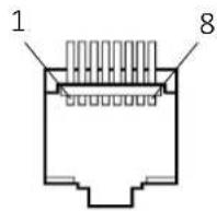
| Pin Number | Function |
| 1 | 12G SDI-1 |
| 2 | 12G SDI-2 |
| 3 | 12G SDI-3 |
| 4 | 12G SDI-4 |
| 5 | Dual-Link 2-S.I. |
| 6 | Quad-Link 2-S.I. |
| 7 | Power |
| 8 | GND |
Functions can be changed in [Remote] section of the menu.
G : LAN(10/100) IN/OUT connector
Used for the future function expansion.
Connects to the LAN (10/100) connector of the network by using 10BASE-T/100BASE-TX LAN cable.
A daisy chain connection using the LAN input/output connectors enables the control of multiple monitors in sequence.
Analog input can be selected with SDI Audio Setting in User Configuration menu.
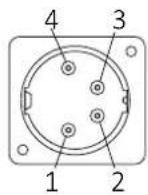
I: DC IN terminal
Connects the DC power supply to the monitor.
DC IN Socket
1:GND
4: +24V
J : AC IN terminal
AC power input connector.
Connects the provided AC power cord.
4. Using the Menu
This monitor is equipped with an OSD menu to make various adjustments and settings such as picture control, input setting, set setting change, etc.
1. Press the MENU button.
The menu appears.
The menu presently selected is shown in gray.
2. Turn SELECT/VOLUME knob to select a menu, then press the knob.
The menu icon presently selected is shown highlighted.


3. Select an item.
Turn SELECT/VOLUME knob to select the item, then press the knob.
The item to be changed is shown highlighted, and the sub menu is displayed on the right.

4. Make the setting or adjustment on an item.
How to change the adjustment level:
To increase the level, turn the SELECT/VOLUME knob right.
To decrease the level, turn the SELECT/VOLUME knob left.
How to change the setting:
Turn the SELECT/VOLUME knob to change the setting, then press the knob to confirm the setting.
**Note - The item displayed in gray cannot be accessed. The item is accessible if it is displayed in white.
To return the display to the previous screen:
Press the MENU button.
To clear the menu:
Press the MENU button.
5. Adjustment Using the Menus
The OSD menu of this monitor consists of the following items.

Status menu (To indicate the current settings)
Format
Color Temp
Brightness
Contrast
Chroma
Aperture
Color Space
Gamma
User Preset
RGB Range
WFM/Vector
Audio Level Meter
Focus Assist
Time Code
Volume
SDI Input
SDI Payload ID
Identifier
Sampling
Picture Rate
Scanning Method
Bit Depth
Link Assignment
Transfer Characteristic
Colorimetry
Model Name?Serial Number
Board Version
Operation Time
Last Calibration Time
Board Temp

Color Temp./Color Space/Gamma menu
Color Temp
Manual Adjustment
R Gain
G Gain
B Gain
R Bias
G Bias
B Bias
Copy From
Color Space
HDR-EOTF
Type
Gamma
Backlight
Camera Log
Default Log Sel.
User Log Sel.
RGB/YCC Range
HDR Auto Setting

Camera Assist menu
Zebra & False Color Setting
Zebra & False Color | Zebra Level Adj. | Zebra Range | Variable White Clipping | Variable Pink Level | Variable Green Level | Variable Black Clipping
False Color Comparison | Wipe Position
Focus Assist Setting | Focus Assist | Color | Frequency
Black Stretch Setting | Black Stretch Max
Gamut Error Setting | Gamut Error
Type Color Space Y Maximum Y Minimum Chroma Maximum Chroma Minimum RGB Maximum RGB Minimum

User Configuration menu
User Preset Setting | Load | Save Function Button Setting | F1 Button | F2 Button | F3 Button | F4 Button | F5 Button
Input Setting | 3G Signal Format SFP Enable | 12G Image Division | Image Division & Link
Audio Delay Setting |Audio Delay(Lip Sync)
Speaker Out / Audio Level Meter Setting | SDI L-Speaker Out | SDI R-Speaker Out | HDMI L/R Speaker Out | Audio Level Meter | Display | Reference | Size/Transparency | Peak Hold Time
Marker Setting 1/2 | Marker Aspect Marker Variable Aspect Center Marker Area Marker Color Aspect Mat Fit Thickness
Marker Setting 2/2 Custom H1 Custom H2 Custom V1 Custom V2
WFM/Vector Setting
WFM/Vector
Type
Intensity
Transparency
Color
Line Select
Line Position
Position
System Setting
Internal Signal
Key LED
OSD Time
OSD position
System Data
Time Code

Remote menu
Parallel Remote
1 Pin
2 Pin
3 Pin
4 Pin
5 Pin
6 Pin
7 Pin
8 Pin
Monitor ID
In-Monitor Display Setting
IMD Type
User Text
Transparency
Text Color
L-Tally Color
R-Tally Color
Network Setting
DHCP
IP Address
Subnet Mask
Gateway
Port No.

Security Setting
Key Lock
Password
User Parameter Lock
Change Password
6. OSD Menu Operations

Status Menu
The Status menu displays the current status of the monitor. The following items are displayed.
Page 1/4
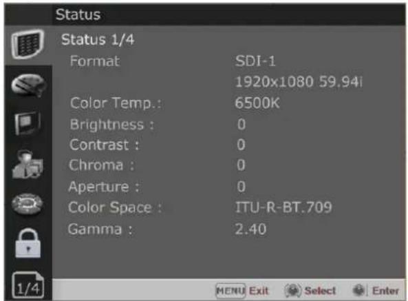
Format
Color Temp
Brightness
Contrast
Chroma
Aperture
Color Space
Gamma
Page 2/4
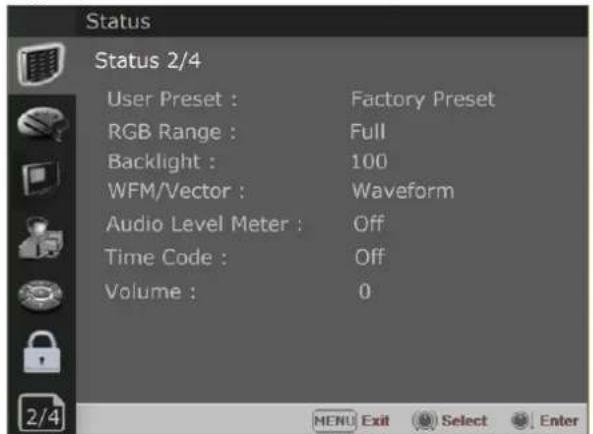
User Preset
RGB Range
Back Light
WFM/Vector
Audio Level Meter
Time Code
Volume
Page 3/4
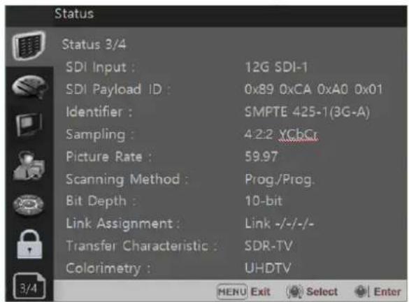
SDI Input
SDI Payload ID
[Non-Text]
Identifier
Sampling
Picture Rate
Scanning Method
Bit Depth
Link Assignment
Transfer characteristics
Colorimetry
*** When the SDI signal is connected, these items are displayed.
Page 4/4

Model Name
Serial Number
Board Version
Operation Time
Last Calibration Time
Board Temp.
Color Temp/Color Space/Gamma Menu
These menus are used for adjusting or setting the color temperature, color space or gamma of the picture.
Page 1/3
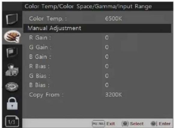
Color Temp.
- Selects the color temperature from among [3200K], [5500K], [6500K], [9300K], [User1], [User2], [User3], [DCI-P3].
**Note - If Color Space is set to [DCI-P3], Color Temp. is fixed to [DCI-P3].
R/G/B Gain
- Displays the R/G/B Gain of the current Color Temperature.
Manual Adjustment
- If you set the Color Temp. to User 1/2/3, the item is changed from black to white, which enables you to adjust the color temperature.
R/G/B Gain/Bias
- Adjusts the color balance(Gain, Bias).
Copy From
- The Gain and Bias data of each Color Temp. are restored to User adjustment.
Page 2/3

Color Space
Selects the color space from among [ITU-R BT.709], [SMPTE-C],[EBU], [DCI-P3], [ITU-R BT.2020], [Native],[ACES Proxy].
HDR-EOTF
Selects the color space from among [SDR], [HDR], [ITU-R BT.1886].
Type
Selects 4 modes of HDR gamma.
- ST-2084 800 * * : This mode displays the absolute brightness up to 800cd/m². So, the highlights over 800cd/m² are clipped.
- ST-2084 1000 : This mode displays the relative brightness up to 1000 cd/m^2 . The part exceeding 1000 cd/m^2 is clipped.
- ST-2084 10000 : The characteristics of LCD panel doesn't allow to produce the ideal brightness required by this standard, so the gamma is displayed in the relative brightness
- HLG -1.15(800) * * (Hybrid Log Gamma): This mode can be selected when the White is 300 cd/m² in HLG..
- HLG -1.0 / 1.1 / 1.2 / 1.3 / 1.4 / 1.5 : These modes allow the user to apply HLG from 1.0 up to 1.5.
- HLG -SG(1.2): HLG gamma is applied to 1.2 and then displayed in the absolute value up to 300cd / m^2 .
- S-Log3: Select the S-Log3(HDR) gamma.
- ST-2084 4000 : This mode displays the relative brightness up to 4000cd / m^2 . The part exceeding 4000cd / m^2 is clipped.

Color Temp/Color Space/Gamma Menu
** 1) OSD Menu of this mode is different, depending on each model's HDR maximum luminance.
HDR maximum luminance
OBM-U318K : 800 cd/m² OBM-U278K : 800 cd/m² OBM-U248K : 600 cd/m²
(2) PQ and HLG gamma is different, depending on each model's luminance. OBM-U318K: ST 2084-800 - HLG-1.15(800) OBM-U278K: ST 2084-800 - HLG-1.15(800) OBM-U248K: ST 2084-600 - HLG-1.10(600)
Gamma
Selects the appropriate gamma mode from 1.00 to 3.00.
**Note - When the HDR-EOTF is set [SDR], this menu becomes activated. - When the color space is set to [Native] or [ACES Proxy], this menu becomes deactivated.
When the color space is set to Native, this menu becomes deactivated.
Back Light
Adjusts the level of the back light level. If the back light value is increased, the screen becomes brighter.
** If the setting in Color Temp. menu and Color Space menu is changed, the value of Back Light returns to the default value of the color calibration in the factory.
Camera Log
Selects a camera log for the input signal. [Off]: Sets off the camera log. [Default]: The log which is selected in [Default Log Sel.] menu is applied. [User]: The log which is selected in [User Log Sel.] menu is applied. [Import Log Data]: Allows the user to save the Log LUT in USB memory stick to the monitor. The saved LUT can be used in User Log.
Default Log Sel
Allows the user to select a camera log among C-Log, Log-C EI 160\~3200, S-Log2 To LC-709, S-Log2 To LC-709TypeA, S-Log2 To Slog2-709, S-Log2 To Cine+709, S-Log2 To LC-709, S-Log3 To LC-709TypeA, S-Log3 To Slog2-709, S-Log3 To Cine+709, J-Log1.
User Log Sel
Selects User Log 1 to 4.
\*\*Note
- If you insert the USB memory stick which contains the user log data to the monitor and push Enter in [Import Log Data] menu, the data is saved to the monitor. - The file name of the user log data is displayed on the OSD up to 15 characters, and the log data file should be placed on the top folder of the USB memory stick.
Ex) If the file name is 'S-log3 to LC709_A.cube', it is displayed as 'S-log3 to LC709' on the OSD.

Color Temp/Color Space/Gamma Menu
Page 3/3

RGB/YCC Range
- Selects Black Level and White Level of RGB/YCC format.
SDI :
Limited : 64(10bit)/256(12bit)\~ 1023(10bit)/4095(12bit) Full : 4/16(Black Level) \~ 1023(10bit)/4095(12bit)
HDMI :
Limited : 64(10bit)/256(12bit)\~ 1023(10bit)/4095(12bit) Full : 0(Black Level) \~ 1023(10bit)/4095(12bit)
HDR Auto Setting
This function allows the monitor to read the Transfer Characteristics and Colorimetry information of Payload identifiers of the ST2082-10 12G SDI signal and adjust HDR automatically.
-Transfer Characteristics : SDR, ST2084-1000, HLG1.2 - Colorimetry : Rec709, Rec 2020

Camera Assist Menu
Page 1/3
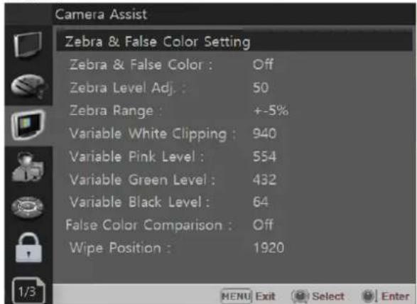
Zebra & False Color
- Evaluates the Luma(Y') level of the input image. If the certain Y' level is set, the pixels with the designated Luma(Y') level are displayed in zebra pattern.
Zebra
Pixels with Y' level over 100% turn to red zebra pattern, and pixels with Y' level under 0% turn to green zebra pattern.
Zebra Level Adjustment
- Adjusts the Y' level as the user wants.
Zebra Range
- Adjusts the Y' level as the user wants.
False Color ARRI
The color pattern is displayed with ARRI camera standard.
| Color | Level | Description |
| red | 99~100% | White clipping |
| yellow | 97~99% | Just below white clipping/white shoulder |
| pink | 52~56% | One stop over medium gray (Caucassian skin) |
| green | 38~42% | 18% neutral gray |
| blue | 2.5~4.0% | Just above black clipping/black slope |
| purple | 0~2.5% | Black clipping |
False Color Variable
This mode allows the user to adjust White clipping, Pink level, Green level, Black Clipping.
Variable White Clipping
- Adjusts White Clipping from 0 to 1023.
Variable Pink Level
- Adjusts Pink level from 0 to 1023.
Variable Green Level
- Adjusts Green level from 0 to 1023.
Variable Black Clipping
- Adjusts Black Clipping from 0 to 1023.

Camera Assist Menu
False Color Comparison
Allows the user to divide the picture side by side, and compare the original image on the left half and the False Color image on the right half.
Wipe Posion
Adjusts the boundary line of the left and right area. Allowed to adjust the boundary line by using the [SELECT/VOLUME] knob.
Page 2/3

Focus Assist
- Controls the aperture level of a video signal and displays images on screen with sharpened edges to help camera focus operation.
Available types are [Color On] and [Mono On].
- [Color On]: The background image is the original color type.
- [Mono On]: The background image is the mono type.
Color
- Selects a color for Focus Assist among [RED], [Green], [Blue], [White], [Yellow], [Cyan].
Frequency
- Adjusts the edge difference level between the edges in an image.
- Available values are from 0% to 100%.
Black Stretch
This mode can be used to increase shadow detail without changing the absolute black level, and without affecting mid-tones. The Black Stretch increases the visibility of subjects in dark areas, not degrading image quality in bright areas.
Max
Adjusts the maximum range to apply the Black Stretch. The range is adjustable from 0 to 1023.

Camera Assist Menu
Page 3/3
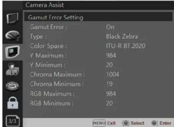
Gamut Error
Turns the Gamut Error [On]/[Off]. Zebra pattern or Color is displayed on the portion whose Y, Cb, Cr and R, G, B are out of the range of the adjusted values based on the color space selected below in [Color Space].
Type
- Black Zebra: The portions outside of the adjusted values are displayed as Black Zebra.
- Black & White Zebra: The portions over Y Maximum, Chroma Maximum, RGB Maximum are displayed as Black Zebra, and the portions below Y Minimum, Chroma Minimum, RGB Minimum are displayed as White Zebera.
- Mono: The portions inside of the adjusted values are displayed as Mono, and the portions outside of the adjusted values are displayed as the color. In this type, black and white area is not recognized.
| Color | Level | Description |
| red | 99~100% | White clipping |
| yellow | 97~99% | Just below white clipping/white shoulder |
| pink | 52~56% | One stop over medium gray (Caucassian skin) |
| green | 38~42% | 18% neutral gray |
| blue | 2.5~4.0% | Just above black clipping/black slope |
| purple | 0~2.5% | Black clipping |
- Default Values
YCbCr
Y Maximum : 984
Y Minimum : 20
Chroma Maximum:1004
Chroma Minimum:19
RGB
Maximum : 984
Minimum : 20

User Configuration Menu
User Configuration consists of the adjustment menus such as[User Preset Setting], [Function Button Setting], [Input Setting], [Output Setting], [Speaker Out / Audio Level Meter Setting], [Marker Setting], [WFM/Vector Setting], [Closed Caption Setting], [System Setting].
Page 1/7

User Preset Setting
[Load] : Load the saved settings in [User Preset1], [User Preset2], [User Preset3], [User Preset4], [User Preset5] and [Factory Preset].
[Save] : Save the current setting status to [User Preset1], [User Preset2], [User Preset3], [User Preset4], or [User Preset5].
** When [User Preset Lock] of [Password] is set [On], [User Preset 1] setting values are protected by password. If you want to save the changed setting values to [User Preset 1], you can enter the password first to set [User Preset Lock] to [Off] and then save the values.
Function Button Setting
- Assigns the function for F1 to F5 buttons on the front panel.
The following functions can be assigned.:
*[H/V Delay],[Color Temp.],[Audio Level Meter], [Time Code],[Zebra & False Color], [Focus Assist], [WFM/Vector],[Camera Log],[HDR-EOTF],[Freeze], [Black Stretch], [False Color Comparison], [Gamut Error], [Cam.log Mapped SDI-Out], [ITU-R BT.709],[ITU-R BT.2020],[DCI-P3] [ST-2084-1000], [ST-2084-4000], [Backlight], [User Preset 1], [User Preset 2], [User Preset 3], [User Preset 4], [User Preset 5].

User Configuration Menu
| - The following functions are assigned in the factory.
[F1 Button] : Color Temp
[F2 Button] : Audio Level Meter
[F3 Button] : Time Code
[F4 Button] : Zebra & False Color
[F5 Button] : Focus Assist
Page 2/7

Input Setting
3G Signal Format
- Selects the format of 3G SDI input signal.
[Auto], [A 4:4:4 YUV 10b], [A 4:4:4 GBR 10b],
[A 4:4:4 YUV 12b], [A 4:4:4 GBR 12b],
[A 4:2:2 YUV 12b],[B DL 4:4:4 YUV 10/12b],
[B DL 4:4:4 GBR 10/12b],[B DL 4:2:2 YUV 12b],
[B DL 4:2:2 YUV 10b 60p]
SFP Enable
- Allows for SFP input to be selected by pushing [SINGLE] button on the front panel.
12G Image Division
- Selects the image division of the 12G-SDI Single Link signal between [2-Sample Interleave] and [Square]
**Payload ID of 12G-SDI 2-Sample Interleave signal and 12G-SDI Square division signal is the same. So, Image Division cannot be detected automatically, and the user has to select it. The default setting is [2-Sample Interleave].
Image Division & Link Order
- Select from [Manual] or [Auto].
[Auto]:
Square / 2-S.I. The input automatically recognizes the VPID (Video Payload ID) embedded in the SDI signal when it is normally present, and even if the input is not connected properly, it splits the image or links in order to reduce user error. Set automatically.
Also, when 12 signals are input, it automatically switches to single mode.
* Quad-Link Squire / 2-S.1 in single mode. In mode It does not change automatically.
Audio delay setting
Audio delay (lip sync)
-Set the delay time between the video and audio signals. (0ms to 170ms). 17 steps.

User Configuration Menu
Page 3/7 Page 4/7
![User Configuration Speaker Out/Audio Level Meter Setting SDI L-Speaker Out : CH 1 SDI R-Speaker Out : CH 2 HDMI L/R Speaker Out : Off Audio Level Meter : 8Ch[G1+G2] Display : Pair Reference : -18dB Size/Transparency : Normal/Full Peak Hold Time : 0 3/7 MENU Exit Select Enter](/content/2026/05/903112/images/abccde25d34475e77825bef731a58c551fc5fc4349346a5e13832e7fffe6a1b7.jpg)
Speaker Out / Audio Level Meter Setting
- Selects the audio channel of the SDI & HDMI input signal.
SDI : Left Speaker Out / Right Speaker Out
- Selects the embedded audio channel for the left and right audio out of the Headphone jack on the front panel of the monitor. Audio channel can be selected among Ch1 \~ Ch16, Analog.
HDMI : L/R Speaker Out
- Selects the embedded audio channel of the HDMI signal. The available modes are [Off], [HDMI On], [Analog On].
Audio Level Meter
Selects the embedded audio mode.
: [Off], [8Ch [G1+G2]], [8Ch [G2+G3]], [8Ch [G3+G4]], [8Ch [G1+G3]], [8Ch [G1+G4]], [8Ch [G2+G4]], [16Ch [G1\~G4]]
** In HDMI input, either [Off] or [HDMI 2Ch] can be selected.
Display
Selects the display method for Audio Level Meter. Available modes are [Group] and [Pair].
** In HDMI input, the mode is fixed to [Pair].
Reference
Selects the default value of Audio Level Meter. Available options are [-18dB] and [-20dB].
Size/Transparency
Selects the size and transparency of Audio Level Meter.
Available options are [Normal/Full], [Normal/Half], [Large/Full], [Large/Half].
Peak Hold Time
Controls the speed rate of Peak Hold Decay Time occurring when the audio volume decreases.

Marker Setting
Marker
- Selects On to display the marker, and Off to deactivate it.
Aspect Marker
Selects the aspect ratio of the marker.
You can select from among [Off], [16:9], [4:3], [4:3 ON AIR], [15:9], [14:9], [13:9], [1.85:1], [2.35:1], [2.39:1], [1.85:1 & 4:3], [1.66:1], [1.896:1], [Variable], [Custom].
\*Variable Aspect
Allows the user to select the aspect ratio from the range between 1.00:1 and 3.00:1.
Center Marker
Selects On to display the center marker and Off not to display it.
Area Marker
Selects the size of the area marker.
You can select from among [Off], [80%], [85%], [88%], [90%], [93%], [100%], [EBU Action 16:9], [EBU Graphic 16:9], [EBU Action 14:9], [EBU Graphic 14:9], [EBU Action 4:3], [EBU Graphic 4:3].
Color
Selects the color of the marker.
You can select from among [White], [Gray], [Red], [Green], [Blue], [Yellow], [Cyan], [Magenta].
Aspect Mat
Darkens the outside of the area of the Aspect Marker. You can select from 0 to 7.
Fit
With Fit On, the Area Marker is displayed relative to the Aspect Marker in use.
With Fit Off, the Area Marker is displayed relative to the incoming video source.
Thickness
Adjusts the thickness of the marker lines. You can select it from 1 to 7.

User Configuration Menu
Page 5/7 Page 6/7

Marker Setting 2/2
This function is activated when the "Aspect Marker" is set [Custom].
Menu > User Configuration 4/8 > Marker >
Aspect Marker > Custom
Custom H1
- Sets the position of the first horizontal marker line.
Custom H2
- Sets the position of the second horizontal marker line.
Custom V1
- Sets the position of the first vertical marker line.
Custom V2
- Sets the position of the second vertical marker line.

WFM/Vector Setting
WFM/Vector
- Select [On] to display the [WFM/Vector] and [Off] not to display.
Type
- You can select from among [WFM],
[VectorScope], [WFM+Vector]
*This function doesn't work when RGB format signal is input.
Intensity
Adjusts the brightness of Waveform and Vectorscope display.
You can select from 1 to 64.
Transparency
Adjusts the transparency level of Waveform and Vectorscope.
[Black]: The background is black. Displayed image is hidden behind the background.
[Half]: The background is transparent. Displayed image can be seen indistinctly behind the Waveform and Vectorscope display.
Color
Selects the color of Waveform monitor.
Available colors are [Green] and [White].
Line Select
Selects [On] to display the Waveform of the line assigned in [Line Position] below.
\*Line Position
Selects the specific horizontal line for
Waveform and Vectorscope.
Increases the value to move the line upwards and decreases the value to move the line downwards.

User Configuration Menu
Page 7/7 Page 1/3
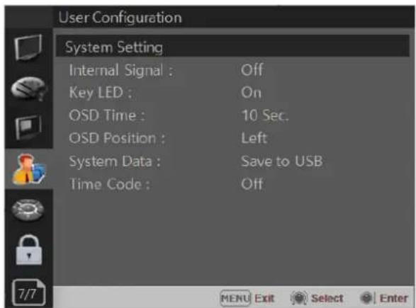
System Setting
Internal Signal
Generates the White Pattern internally.
The selectable range is from 100%(White) to 0%(Black), ColorBar.
Key LED
Sets On to turn on the LED of the keys, and sets Off to turn off the LED of the keys.
OSD Time
Adjusts the display time of the OSD menu.
[10 Sec.]: The OSD menu will be disappeared after 10 seconds.
[20 Sec.]: The OSD menu will be disappeared about 20 seconds.
[30 Sec.]: The OSD menu will be disappeared about 30 seconds.
[On]: The OSD menu will not be disappeared.
OSD Position
Sets the position of OSD. Selects [Left] or [Left Top].
System Data
-[Save to USB] Saves the current settings of the monitor to the USB memory.
-[Copy from USB] Recalls the settings saved in the USB memory, and load them to the monitor.
(User preset settings are also saved as values loaded from USB memory.)
- The R/G/B gain obtained by color calibration is not saved in USB memory or loaded to the monitor.
- If User Preset Lock is turned on in Security, User Preset 1 among the set values retrieved from USB memory is not saved in the monitor and retains the existing values.
Time Code
-Selects the type of the time code to be displayed. [VITC]: To display the VITC time code [LTC]: To display the LTC time code

Remote Menu

Parallel Remote
Selects the Parallel Remote connector pins for which you want to change the function.
Various functions can be assigned to pin 1 to 6. The following is the lists of the functions which can be assigned to the pins.
[--]
[12G SDI-1]
[12G SDI-2]
[12G SDI-3]
[12G SDI-4]
[D-Link 2-S.I.]
[Q-Link 2-S.I.]
[D-Link SFP]
[Square SDI]
[Quad SDI]
[HDMI]
[SFP-1]
[SFP-2]
[Zero Scan]
[1:1 Scan]
[4:3 Aspect]
[16:9 Aspect]
[Auto Aspect]
[H/V Delay]
[Blue Only]
[Blue Only Mono]
[Marker]
[Tally R]
[Tally G]
[User Preset 1]
[User Preset 2]
[User Preset 3]
[User Preset 4]
[User Preset 5]
[ITU-R BT.709]
[ITU-R BT.2020]
[HDR-EOTF]
[C.Log Default]
[C.Log User]
** [--]: No function is assigned
*7 Pin: For Power On and Off only
*8 Pin: For Ground only

Remote Menu
Page 2/3
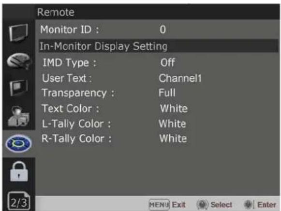
Monitor ID
Sets the ID of the monitor to control the monitor through Serial Remote or Network.
In-Monitor Display Setting
The monitor supports "TSL UMD Protocol – V3.1 & V5.0" provided by Television System Ltd. [Transparency], [Text Color], [Left Tally Color], [Right Tally Color] can be set in the setting menu.
** The monitor displays English alphabet, numbers, Symbolic codes.
** Up to 16 characters can be displayed in English.
IMD Type
- Selects the In-Monitor Display type. Available modes are [Off], [TSL V3.1], [TSL V5.0], [User].
User Text
-If the IMD type is User, the user can set the ASCII character table up to 8 characters arbitrarily.
Transparency
- Selects [Full] or [Half] for the background of IMD.
-[Full]: The background is black. Displayed image is hidden behind the background.
-[Half]: The background is transparent. Displayed image can be seen indistinctly behind the IMD display.
Text Color
- Selects the color of text displayed in IMD.
- The user can select from among [White], [Gray], [Red], [Green], [Blue], [Yellow], [Cyan], [Magenta].
Left Tally Color
- Selects the color of left tally lamp displayed in IMD.
- The user can select from among [White], [Gray], [Red], [Green], [Blue], [Yellow], [Cyan], [Magenta].
Right Tally Color
- Selects the color of right tally lamp displayed in IMD.
- The user can select from among [White], [Gray], [Red], [Green], [Blue], [Yellow], [Cyan], [Magenta].
Page 3/3

Network Setting
DHCP
- Toggle DHCP On or Off. DHCP allows your monitor to receive an IP address from your network for remote control via various programs.
IP Address, Subnet Mask & Gateway
- The user can manually configure network settings when DHCP is disabled.
Port No.
- Sets the port number.

Remote Menu
\*\*Note
SFP module support is activated only when the module is first connected and the monitor power is turned on.

Embrionix emSFP Setting 1/2
SFP Select
- Select the optical module to be used. (SFP-1, SFP-2)
Primary/Secondary
- Select the page of emSFP flow. (Primary/Secondary)
Flow
- Select emSFP flow. (Video/Audio1/Audio2/Audio3/Audio4/Anciallary)
Source IP Address/Port No.
- Set Source IP/Port.
Dest. IP Address/Port No.
- Set the destination IP/Port.
Format
- Set the video signal format. (720p50,720p59.94,720p60,720p23.98,720p24,720p25,720p29.97,720p30,1080p23.98,1080p24,1080p25,1080psf25,1080psf29.97,1080psf30,1080p30,1080psf30,1080i50,1080i59.94,1080i60,3GA 1080p50,3GA 1080p59.94,3GA 1080p60,2048x1080p23.98,2048x1080p24,2048x1080p25,2048x1080p29.97,2048x1080p30,3GA 2048x1080p48,3GA 2048x1080p50,3GA 2048x108p59.94,3GA 2048x1080p60)

Embrionix emSFP Setting 2/2
PTP Mode
- Set the Precision time protocol (PTP) mode. (Multicast, Hybrid, Unicast)
PTP Master
- Set the UUID (Universally Unique Identifier) mode. (Auto, Manual)
PTP Domain
- Set the domain number of the PTP Master. (0-255)
Video flows sender type
- Set the sender type of the emSFP video flow. (Narrow, Narrow linear, Wide)
Controller IP Address, Subnetmak, Port No.
- Shows emSFP's control IP/Subnetmask and Port No.

Security Menu
Page 1/1

Security Setting
Key Lock
When Key Lock function is set On, the change of the menu settings and functions doesn't work.
** The same function as [Key Lock] button on the front panel.
Password
-This function allows the user to protect the setting values through password.
-When the Password lock is applied, the functions and the setting values can be changed, but they are not saved.
-When you protect the setting values with a password, set a four-digit number.
-The initial password is 0000.
-When you use [Password], change the initial password first.
User Parameter Lock
Selects [On] to protect the setting values. Selects [Off] to not protect by the password.
Change Password
Changes the password.
7. Scan Mode Image
4K/QFHD Mode
The LCD panel resolution of OBM-U318K/278K/248K is QFHD(16:9) 3840x2160, so if the input signal is 3840x2160 1:1 mapping is supported. If the input signal is DCI 4K(4096x2160), 1:1 mapping is not supported.
[Zero Scan]
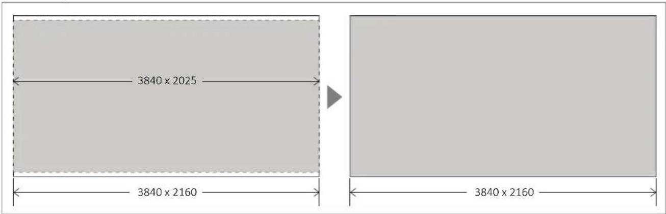
When the 4096x2160 signal is fed, if you select Zero Scan using [Scan] button on the front panel, the picture is scaled to be displayed on the panel of 3840x2025 resolution with maintaining 1.89:1 ratio.
[1:1 Scan]

When 1:1 Scan mode is selected with the [Scan] button in 1920x1080, 1280x720 mode, etc., it is placed in the center of the screen as above. A 1:1 mapped image is output.
8. Connecting the SDI Signals
Single Link 12G/6G/3G/HD-SDI, Dual-Link 6G/3G-SDI, Quad Link 12G/6G/3G/-SDI signals can be Input to the SDI In connectors of this monitor.
Up to 4-channel Single Link 12G/6G/3G/HD-SDI signals, 1-channel Dual-Link 6G/3G-SDI or 1-channel Quad-Link 12G/6G/3G-SDI signals can be input. Use the appropriate input connectors depending on the input signal, referring to the table below.
Single-Link Signal
| Connector | Input signal |
| 12G SDI -1 | 12G/6G/3G/HD |
| 12G SDI -2 | 12G/6G/3G/HD |
| 12G SDI -3 | 12G/6G/3G/HD |
| 12G SDI -4 | 12G/6G/3G/HD |
Dual-Link 3G -SDI Signal
* 2-sample interleave division signals
| Connector | Input signal |
| 12G SDI -1 6G/3G | SDI Link1 |
| 6G/3G SDI Link2 12G SDI -2 |
Quad-Link Signal
* 2-sample interleave division signals
| Connector | Input signal |
| 12G SDI -1 | 12G/3G Link1 |
| 12G SDI -2 | 12G/3G Link2 |
| 12G SDI -3 | 12G/3G Link3 |
| 12G SDI -4 | 12G/3G Link4 |
Quad-Link Square Signal
| Connector | Input signal |
| 12G SDI -1 | 12G/3G/HD Link1 |
| 12G SDI -2 | 12G/3G/HD Link2 |
| 12G SDI -3 | 12G/3G/HD Link3 |
| 12G SDI -4 | 12G/3G/HD Link4 |
Image of Square division signals
| Sub-Image1 (upper-left screen) | Sub-Image2 (upper-right screen) |
| Sub-Image3 (lower-left screen) | Sub-Image4 (lower-right screen) |
* Only progressive signals are supported in Dual-Link and Quad-Link modes.
9. Available Signal Formats
This monitor is applicable to the following signal formats
Single HD-SDI
| Signal System | Signal Format |
| 1920 x 1080 /23.98, 24, 25, 29.97, 30p/Psf, 50, 59.94, 60i | 4:2:2 YCbCr 10bit |
| 2048 x 1080 /23.98, 24, 25, 29.97, 30p/Psf | 4:2:2 YCbCr 10bit |
| 1280 x 720 /23.98, 24, 25, 29.97, 30, 50, 59.94, 60p | 4:2:2 YCbCr 10bit |
Single 3G-SDI
| Signal System Signal Format | ||
| 1920 x 1080 /47.95, 48, 50, 59.94, 60p | 4:2:2 YCbCr 10bit | Level A / Level B-DL |
| 1920 x1080 /23.98, 24, 25, 29.97, 30p/Psf, 50, 59.94, 60i | 4:4:4 RGB 10bit4:4:4 YCbCr 10bit4:4:4 RGB 12bit4:4:4 YCbCr 12bit | Level A / Level B-DL |
| 2048 x1080 /47.95, 48, 50, 60p | 4:2:2 YCbCr 10bit | Level A / Level B-DL |
| 2048 x 1080 /23.98, 24, 25, 29.97, 30p/Psf | 4:4:4 RGB 10bit4:4:4 YCbCr 10bit4:4:4 RGB 12bit4:4:4 YCbCr 12bit | Level A / Level B-DL |
| 1280x 720 /23.98, 24, 25, 29.97, 30, 50, 59.94, 60p | 4:4:4 RGB 10bit4:4:4 YCbCr 10bit | Level A |
Single 6G-SDI
| Signal System Signal Format | |
| 3840 x2160 /23.98, 24, 25, 29.97, 30p | 4:2:2 YCbCr 10bit |
| 4096 x2160 /23.98, 24, 25, 29.97, 30p | 4:2:2 YCbCr 10bit |
Single 12G-SDI
| Signal System Signal Format | |
| 3840 x2160 /23.98, 24, 25, 29.97, 30, 47.95, 48, 50, 59.94, 60p | 4:2:2 YCbCr 10bit |
| 4096 x2160 /23.98, 24, 25, 29.97, 30, 47.95, 48, 50, 59.94, 60p | 4:2:2 YCbCr 10bit |
Dual-Link (4K) 3G-SDI
| Signal System | Signal Format | |
| 3840 x2160 /23.98, 24, 25, 29.97, 30p | 4:2:2 YCbCr 10bit | Level B-DS 2-sample interleave division |
| 4096 x2160 /23.98, 24, 25, 29.97, 30p | 4:2:2 YCbCr 10bit | Level B-DS 2-sample interleave division |
Dual-Link (4K) 6G-SDI
| Signal System Signal Format | ||
| 3840 x2160 /50, 59.94, 60p | 4:2:2 YCbCr 10bit | 2-sample interleave division |
| 4096 x2160 /50, 59.94, 60p | 4:2:2 YCbCr 10bit | 2-sample interleave division |
Quad-Link (4K) HD-SDI
| Signal System Signal Format | ||
| 3840 x2160 /23.98, 24, 25, 29.97, 30p | 4:2:2 YCbCr 10bit | 2-sample interleave division/Square division |
| 4096 x2160 /23.98, 24, 25, 29.97, 30p | 4:2:2 YCbCr 10bit | 2-sample interleave division/Square division |
Quad-Link (4K) 3G-SDI
| Signal System Signal Format | |||
| 3840 x2160 /50, 59.94, 60p | 4:2:2 YCbCr 10bit | Level A / Level B-DL | 2-sample interleave division/Square division |
| 3840 x2160 /23.98, 24, 25, 29.97, 30p | 4:4:4 RGB 10bit4:4:4 YCbCr 10bit4:4:4 RGB 12bit4:4:4 YCbCr 12bit | Level A / Level B-DL | |
| 4096 x 2160 /47.95, 48, 50, 59.94, 60p | 4:2:2 YCbCr 10bit | Level A / Level B-DL | 2-sample interleave division/Square division |
| 4096 x 2160 /23.98, 24, 25, 29.97, 30p | 4:4:4 RGB 10bit4:4:4 YCbCr 10bit4:4:4 RGB 12bit4:4:4 YCbCr 12bit | Level A / Level B-DL | |
Quad-Link (4K) 12G-SDI
| Signal System Signal Format | ||
| 3840 x2160 /50, 59.94, 60p | 4:2:2 YCbCr 10bit | 2-sample interleave division |
| 4096 x2160 /50, 59.94, 60p | 4:2:2 YCbCr 10bit | 2-sample interleave division |
HDMI
| Signal System | |
| 640 x 480p@59.94 / 60 | 4:4:4 RGB 8 / 10 / 12bit4:4:4 YCbCr 8 / 10 / 12bit4:2:2 YCbCr 12bit |
| 720 x 480p@59.94 / 60 | |
| 720 x 576p@50 | |
| 1280 x 720p@50 / 59.94 / 60 | |
| 1920 x 1080i@50 / 59.94 / 60 | |
| 1920 x 1080p@23.98 / 24 / 25 / 29.97 / 30 / 50 / 59.94 / 60 | |
| 2048 x 1080p@23.98 / 24 / 25 / 29.97 / 30 / 47.95 / 48 / 50 / 59.94 / 60 | |
| 3840 x 2160p@23.98 / 24 / 25 / 29.97 / 30 / 50* / 59.94* / 60* | 4:4:4 RGB 8bit4:4:4 YCbCr 8bit4:2:2 YCbCr 12bit*Supports 4:4:4 RGB 8bit only |
| 4096 x 2160p@23.98 / 24 / 25 / 29.97 / 30 / 50* / 59.94* / 60* | |
| 800 x 600p@60 | 4:4:4 RGB 8 / 10 / 12bit4:4:4 YCbCr 8 / 10 / 12bit4:2:2 YCbCr 12bit |
| 1024 x 768p@60 |
10. Key Functions
Versatile 4K/QFHD Input Capability
The OBM-U**8K series is equipped with standard 12G-SDI input interface(x4) and support 4K/8K Quad Link 2-sample interleave signals and 4K Quad Link Square Division signals.
The OBM-U**8K Series can accept up to 7680x4320/23.98,24,25,29.97,30,50,59.94,60p and 8192x4320/23.98,24,25,29.97,30,50,59.94,60p

natural_image
Tennis player in red uniform mid-swing with racket and ball on green court (no visible text or symbols)4K Waveform Monitor and Vector Scope Display
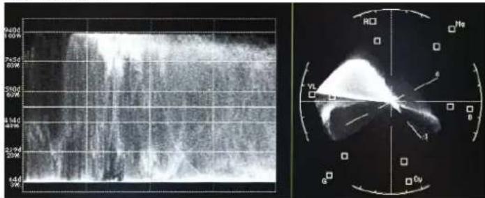
These features enable users to monitor sources using the internal Waveform and Vector Scope. Waveform Wide mode is supported, and both Waveform and Vector Scope can be displayed simultaneously.

natural_image
Eagleerman holding a horse with wings spread, standing in front of mountainous terrain under a clear blue sky (no text or symbols visible)High Dynamic Range(HDR) Display Function
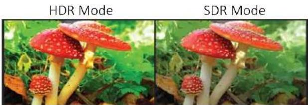
The OBM U**8K series provides the function to display the High Dynamic Range footage. Postium HDR function allows users to view both highlights and shadow detail of scenes at the same time, thus resulting in more natural and realistic images. The OBM U**8K series supports PQ EOTF (SMPTE ST 2084), Hybrid Log Gamma and S-Log3.
natural_image
Two side-by-side photos of red and white mushrooms in a forest setting, labeled HDR Mode and SDR Mode (no text on mushrooms themselves)OBM-HDR provides the function of comparing HDR and SDR(Standard Dynamic Range) on the displayed image on the OBM series simultaneously.
HDR SDR
natural_image
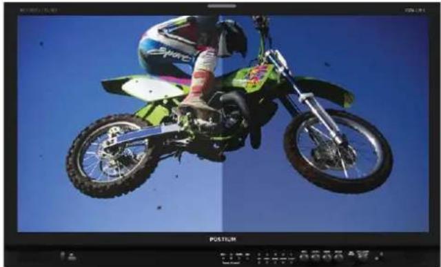
Green and white racing motorcycle mid-air against a clear blue sky, captured in motion with no visible text or symbols.Wide Color Space Supporting DCI-P3 and ITU-R BT.2020
The wide color gamut and the advanced 3D LUT function enable the OBM U**8K series to reproduce various color spaces accurately and the excellent grayscale. You can select from color gamuts such as DCI-P3, ITU-R BT.2020, ITU-R BT.709, SMPTE-C, EBU, Native.

radar
| Model | Value | | --------------- | ----- | | ITU-R BT.2020 | 510 | | DCI-P3 | 520 | | EBU | 530 | | SMPET-C | 550 | | OBM-U240 NATIVE | 570 | | ITU-R BT.2020 | 590 | | DCI-P3 | 610 | | EBU | 700-780| | SMPET-C | 490 | | OBM-U240 NATIVE | 480 | | ITU-R BT.2020 | 470 | | DCI-P3 | 380-410| | EBU | 470 | | SMPET-C | 480 | | OBM-U240 NATIVE | 490 |Adjustable Gamma
Gamma value is adjustable from 1.0 to 3.0 as user's preference to monitor in the dark area of the picture. Any pictures taken in either light or dark environment can be easily watched or analyzed.

natural_image
Colorful parachute in mid-air against a clear blue sky, with a person visible below (no text or symbols)Gamma 1.8

natural_image
Colorful parachute in mid-air against a clear blue sky, with a person visible below (no text or symbols)Gamma 2.4
Remote Control via Ethernet
The OBM U**8K series can be connected via Ethernet connection and controlled remotely on the network.





Focus Assist
This function controls the aperture level of a video signal, and displays images on screen with sharpened edges to help camera focus operation.

natural_image
Two seagulls standing on red rock formations against a clear blue sky (no text or symbols visible)Camera Log Selection
The OBM-U**8K series have the built-in camera LUT of the various camera manufacturers. It allows users to load the following camera logs. Log-C, C-Log / S-Log2, S-Log3 / J-Log1
The more camera LUTs will be updated.
SFP Optical Connector
The OBM U**8K series has the SFP interface, which allows to use the various SFP modules which can fit any possible broadcast applications.
Custom 3D LUT File Import
The OBM-U**8K Series allow the user to import 3D Look-up Table for accurate and consistent color matching between individual displays as well as using customized 'looks' that have been created by 3rd party color-grading applications. 32^ 3 , 33^ 3 , 64^ 3 and 65^ 3 cube file is supported.

natural_image
Two young girls in white wedding dresses sitting on a leafy green path under trees (no text or symbols visible)
natural_image
Two young girls in white wedding dresses sitting on a leafy green path surrounded by trees (no text or symbols visible)Various 4K/12G Display Modes
Single Link 12G-SDI

Dual Link 2-Sample Interleave(2-SI)
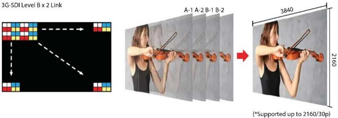
Quad Link 2 Sample Interleave (2SI)
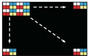
Each link contains a full image at 1/4 resolution. 2SI mode uses four Sub-image and alternates the samples every two pixels and every line instead of slitting the image into four quadrants.
HD/3G/12K-SDI x 4 ink
flowchart
graph TD
    A["Top-Left Grid Block"] --> B["Bottom-Right Grid Block"]
    B --> C["Right-Left Grid Block"]
    style A fill:#f9f,stroke:#333
    style B fill:#bbf,stroke:#333
    style C fill:#dfd,stroke:#333
A B C D

natural_image
Woman playing violin with strings, showing motion sequence (no text or symbols)
natural_image
Woman playing violin with string, no visible text or symbols2160
Black Stretch
The Black Stretch increases the visibility of subjects in dark areas, not degrading image quality in bright areas. This mode can be used to increase shadow detail without changing the absolute black level, and without affecting mid-tones.
Black Stretch Off

natural_image
Exterior view of a stone arch bridge spanning a river, with red-roofed buildings in the background (no signage or text visible)Black Stretch On

natural_image
Exterior view of a stone arch bridge spanning a river, with red-roofed buildings and greenery in the background (no signage or text visible)False Color
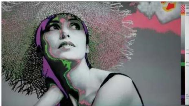
This function evaluates the Luma(Y') level of the input image. If the certain Y' level is set, the pixels with the designated Luma(Y') level are displayed with the zebra pattern or the color pattern. There are three modes in OBM False Color.
Zebra
This mode displays the Luma(Y') level of the input image in zebra pattern.

natural_image
Portrait of a woman wearing a straw hat against a blue sky with clouds (no text or symbols visible)False Color Variable
This mode allows the user to adjust White clipping, Pink level, Green level, Black Clipping.

natural_image
Stylized portrait of a woman with green facial features and purple headscarf, looking upward (no text or symbols)False Color ARRI
The color pattern is displayed with ARRI camera standard.
natural_image
Stylized illustration of a woman with purple headscarf and green facial features, looking upward (no text or symbols)False Color Comparison
This function enables the user to divide the picture side by side, and compare the original image on the left half and the False Color image on the right half.

natural_image
Portrait of a woman wearing a straw hat, looking upward with colorful abstract background (no text or symbols)Gamut Error
The total range of the SDI 10bit signal is 0 to 1023. The range 0 to 3 and 1020 to 1023 are the reserved values for Sync, and the total video signal range is 4 to 1019.
In a video signal, each primary component should lie between 0 and 100% of the video range between black level and peak level (R and G and B). Ideally, video levels should lie within the specified limits so that programs can be distributed without adjustment.
100% White pattern: Y - 940, Cb - 512, Cr - 512. 0% Black pattern: Y - 64, Cb - 512, Cr - 512
Expected Video Range: 64 to 940
In practice, it is difficult to avoid generating signals slightly out of range, and it is considered reasonable to allow a small tolerance. Therefore, the EBU recommends that the RGB components and the corresponding Luminance (Y) signal should not normally exceed the “preferred minimum/maximum” range of digital sample levels in the table below.
| SystemBit Depth | Range in Digital Sample (Code) Values | ||
| Expected Video Range | Preferred Min. / Max. Total | Video Signal Range | |
| 10 bit 64 - 940 20 - 984 4 - 1019 | |||
*References: EBU R 103 Version 2.0 page 4, Annex 1
Type 1: Black Zebra
When the targeted color space is selected as BT.709, the pixels outside of the targeted color space are displayed as Black Zebra.
The pixels over Y Maximum, Chroma Maximum, RGB Maximum are displayed as Black Zebra, and the pixels below Y Minimum, Chroma Minimum, RGB Minimum are also displayed as Black Zebra.

natural_image
Red vintage automobile with open canopy and yellow wheels, parked outdoors near trees (no visible text or symbols)
natural_image
Red vintage car with yellow wheel rim and black trim, parked outdoors with green foliage in background (no visible text or symbols)Type 2: Black & White Zebra
When the targeted color space is selected as BT.709, the pixels outside of the targeted color space are displayed as Black or White Zebra. The pixels over Y Maximum, Chroma Maximum, RGB Maximum are displayed as Black Zebra, and the pixels below Y Minimum, ChromaMinimum, RGB Minimum are displayed as White Zebra.

natural_image
Red vintage red and black automobile with yellow wheels, parked outdoors near trees (no visible text or symbols)
natural_image
Red vintage red car with black textured trim and yellow wheel rim, parked outdoors with trees in background (no visible text or symbols)Type 3: Mono
When the targeted color space is selected as BT.709, the pixels inside of the targeted color space are displayed as Mono, and the pixels outside of the targeted color space are displayed as the color. In this type, black and white area is not recognized.

natural_image
Vintage black-and-white photo of a vintage military-style vehicle with camouflage pattern, parked outdoors (no visible text or symbols)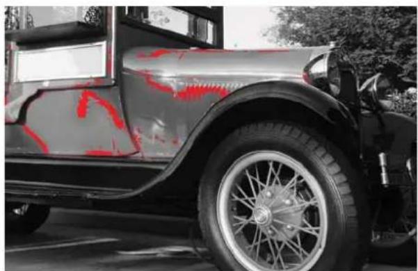
natural_image
Side view of a vintage silver car with red painted paint on the wheel, parked outdoors (no visible text or symbols)*Simulated image
Supports 12G-SDI Single Link Square Division signal format
The OBM-U**8K series can display 12G-SDI Single Link 4K/UHD signals as well as 3G-SDI Quad Link signals. This is already a very useful feature, compared to competitors' monitors.
Most of the single link 12G-SDI signals are displayed as 2-S.I. format on the screen. But, the single link 12G-SDI signals with Square Division format are increasing. In order to meet this requirement in the location and studio, the OBM-U**8K series support both 12G-SDI Single Link 2-S.I. mode and 12G-SDI Single Link Square Division mode.

Meets the Return Loss Standard, SMPTE ST 2082-1:2015
In the professional broadcasting video industry, Return Loss is an important parameter that measures the reflected signal that bounces back from a terminated device. If the broadcast monitor has the poor return loss, the level of reflected signal negatively impacts the signal integrity of the loop-out signal.
The OBM-U**8K monitors meets the requirements of Return Loss specified in SMPTE ST 2081-1:2015, so that the OBM-U**8K monitors provides the high signal fidelity.

line
| Frequency | Return Loss | | --------- | ----------- | | 5 MHz | -15 dB | | 3 GHz | -15 dB | | 1.485 GHz| -10 dB | | 6 GHz | -7 dB | | 12 GHz | -4 dB |HDR Waveform
When HDR more is set on, HDR Waveform is displayed on screen.
HDR Mode + HDR Waveform

natural_image
Worker in safety gear performing a grinding operation with bright sparks flying (no visible text or symbols)HDR Waveform

SDR Mode + SDR Waveform

natural_image
Worker in safety gear grinding metal with sparks, inset shows close-up of industrial equipment (no visible text or symbols)SDR Waveform
In-Monitor Display(IMD) Function
The image source names and tally information can be displayed on the screen, with an external remote function via Ethernet. The TSL system protocol is supported. The color of the source name and tally color can be selectable among White, Red, Green, Blue, Yellow, Cyan, Magenta.


Custom 3D LUT File Import
The OBM series allow the user to import 3D Look-up Table for accurate and consistent color matching between individual displays. as well as using customized 'looks' that have been created by 3rd party color-grading applications. 32^ 3 , 33^ 3 , 64^ 3 and 65^ 3 cube file is supported.

natural_image
Coastal scene with a thatched-roof pier, turquoise water, and birds perched on the dock under a partly cloudy sky (no text or symbols visible)

natural_image
Scenic tropical beach scene with a thatched-roof pier, birds perched on the shore, and turquoise water under a blue sky with clouds (no text or symbols visible)Various Markers
The OBM U/X series can display various markers, including aspect marker, area marker, and center marker. In addition, the detailed display settings of each marker are allowed. For example, the color, brightness, horizontal/vertical position, and thickness of aspect markers can all be adjusted.

natural_image
Flying duck in flight against a blurred sky with golden bokeh background (no text or symbols)Display various markers

natural_image
A grayscale photo of a duck in flight with golden bokeh background (no text or symbols)Display Color markers

natural_image
Flying duck in flight against a golden sunset background (no text or symbols visible)Aspect Mat 0 Aspect Mat 2

natural_image
Flying geese in flight against a golden sunset background (no text or symbols visible)
natural_image
Flying duck in flight against a golden sunset sky with bokeh reflection (no text or symbols)
natural_image
Two geese in flight with golden light reflected on water, no text or symbols visibleAspect Mat 5 Aspect Mat 7
11. Product Specifications
Specifications (OBM-U178K)
| ITEM OBM-U178K | |||
| Input | 4 x BNC | 12G/6G/3G/HD | |
| 1 x HDMI | HDMI 2.0 | ||
| 2 x SFP | SFP | ||
| Output | 4 x BNC | 12G/6G/3G/HD/4 Active Loop Output | |
| Input Signal Format | SMPTE ST 2082-12(12G Quad 8K) | 4320p(60/59.94/50) | |
| SMPTE ST 2082-10(12G Single) | 2160p(60/59.94/50/30/29.97/25/24/23.98) | ||
| SMPTE ST 2081-11(6G Dual) | 2160p(60/59.94/50) | ||
| SMPTE ST 2081-10(6G Single) | 2160p(30/29.97/25/24/23.98) | ||
| SMPTE ST 425-AB | 1080p(60/59.94/50/30/29.97/25/24/23.98/30sF/29.97sF/25sF/24sF/23.98sF) / 1080i (60/59.94/50) | ||
| SMPTE ST 274 | 1080p(30/29.97/25/24/23.98/24sF/23.98sF) | ||
| 1080i (60/59.94/50) | |||
| SMPTE ST 296 | 720p(60/59.94/50) | ||
| SMPTE ST 260 | 1920 x 1035i(60/59.94) | ||
| SMPTE ST 2048 | 2048 x 1080p(24/23.98/24sF/23.98sF) | ||
| HDMI 2.0 | ~ 2160p(60) | ||
| SFP | 12Gbps, 6Gbps, 2.970Gbps, 1.485Gbps, 270Mbps | ||
| Audio In/Out | 1 x Phone Jack In | Line In(Stereo) | |
| 1 x Phone Jack Out | H/P Out(Front, Stereo) | ||
| 2 x Speaker Out | Stereo | ||
| Display | Size | 17.3" LCD | |
| Resolution | 3840 x 2160 (16:9) | ||
| Pixel Pitch | 0.09945mm | ||
| Color | 1.064B Colors(8bit+Hi FRC) | ||
| Viewing Angle | 178(H), 178(V) | ||
| Luminance of White | 1500cd/m2 | ||
| Contrast | 1000 : 1 | ||
| Display Area (H x V) | 381.89 x 214.81 (mm) | ||
| General | 2 x Ethernet | Control/Update, RJ-45P Input / Output | |
| 1 x GPIO | GPI-7 Port, RJ-45P Jack | ||
| 2 x Serial | RS-422 Jack, RJ-45P Input / Output | ||
| 1 x USB | For Firmware Update, Color Calibration | ||
| Power Requirements | AC(100-230V, 50/60Hz)/DC 24V | ||
| Power Consumption | TBD | ||
| Operating Temperature | 0°C ~ 40°C(32°F~104°F) | ||
| Operating Humidity | 20% ~ 80% RH | ||
| Weight | Main Body : 6.6kg / 14.55lbs (With Stand : 7.7kg / 16.97lbs) | ||
| Dimensions (WxHxD) | Main Body : 436 x 310 x 81 mm(With Stand : 445 x 329 x 120mm) | ||
| Main Body : 17.16 x 12.20 x 3.18inch (With Stand : 17.51 x 12.20 x 4.72 inch) | |||
| Accessories | Power Cable | ||
| Option | Wall Mount Kit/ Carrying Case | ||
* Specifications are subject to change without prior notice for the product quality improvement.
Specifications (OBM-U248K)
| ITEM OBM-U248K | |||
| Input | 4 x BNC | 12G/6G/3G/HD | |
| 1 x HDMI | HDMI 2.0 | ||
| 2 x SFP | SFP | ||
| Output | 4 x BNC | 12G/6G/3G/HD/4 Active Loop Output | |
| Input Signal Format | SMPTE ST 2082-12(12G Quad 8K) | 4320p(60/59.94/50) | |
| SMPTE ST 2082-10(12G Single) | 2160p(60/59.94/50/30/29.97/25/24/23.98) | ||
| SMPTE ST 2081-11(6G Dual) | 2160p(60/59.94/50) | ||
| SMPTE ST 2081-10(6G Single) | 2160p(30/29.97/25/24/23.98) | ||
| SMPTE ST 425-AB | 1080p(60/59.94/50/30/29.97/25/24/23.98/30sF/29.97sF/25sF/24sF/23.98sF) / 1080i (60/59.94/50) | ||
| SMPTE ST 274 | 1080p(30/29.97/25/24/23.98/24sF/23.98sF) | ||
| 1080i (60/59.94/50) | |||
| SMPTE ST 296 | 720p(60/59.94/50) | ||
| SMPTE ST 260 | 1920 x 1035i(60/59.94) | ||
| SMPTE ST 2048 | 2048 x 1080p(24/23.98/24sF/23.98sF) | ||
| HDMI 2.0 | ~ 2160p(60) | ||
| SFP | 12Gbps, 6Gbps, 2.970Gbps, 1.485Gbps, 270Mbps | ||
| Audio In/Out | 1 x Phone Jack In | Line In(Stereo) | |
| 1 x Phone Jack Out | H/P Out(Front, Stereo) | ||
| 2 x Speaker Out | Stereo | ||
| Display | Size | 23.74" LCD | |
| Resolution | 3840 x 2160 (16:9) | ||
| Pixel Pitch | 0.1369mm | ||
| Color | 1.073B Colors, 10Bit | ||
| Viewing Angle | 178(H), 178(V) | ||
| Luminance of White | 540cd/m2 | ||
| Contrast | 1200 : 1 | ||
| Display Area (H x V) | 525.65 x 295.70 (mm) | ||
| General | 2 x Ethernet | Control/Update, RJ-45P Input / Output | |
| 1 x GPIO | GPI-7 Port, RJ-45P Jack | ||
| 2 x Serial | RS-422 Jack, RJ-45P Input / Output | ||
| 1 x USB | For Firmware Update, Color Calibration | ||
| Power Requirements | AC(100-230V, 50/60Hz)/DC 24V | ||
| Power Consumption | TBD | ||
| Operating Temperature | 0°C ~ 40°C(32°F~104°F) | ||
| Operating Humidity | 20% ~ 80% RH | ||
| Weight | 10.5kg / 23.14lbs | ||
| Dimensions (WxHxD) | 605 x 400 x 140mm | ||
| 23.81 x 15.74 x 5.51inch | |||
| Accessories | Power Cable | ||
| Option | Wall Mount Kit/ Carrying Case | ||
* Specifications are subject to change without prior notice for the product quality improvement.
Specifications (OBM-U278K)
| ITEM OBM-U278K | |||
| Input | 4 x BNC | 12G/6G/3G/HD | |
| 1 x HDMI | HDMI 2.0 | ||
| 2 x SFP | SFP | ||
| Output | 4 x BNC | 12G/6G/3G/HD/4 Active Loop Output | |
| Input Signal Format | SMPTE ST 2082-12(12G Quad 8K) | 4320p(60/59.94/50) | |
| SMPTE ST 2082-10(12G Single) | 2160p(60/59.94/50/30/29.97/25/24/23.98) | ||
| SMPTE ST 2081-11(6G Dual) | 2160p(60/59.94/50) | ||
| SMPTE ST 2081-10(6G Single) | 2160p(30/29.97/25/24/23.98) | ||
| SMPTE ST 425-AB | 1080p(60/59.94/50/30/29.97/25/24/23.98/30sF/29.97sF/25sF/24sF/23.98sF) / 1080i (60/59.94/50) | ||
| SMPTE ST 274 | 1080p(30/29.97/25/24/23.98/24sF/23.98sF) | ||
| 1080i (60/59.94/50) | |||
| SMPTE ST 296 | 720p(60/59.94/50) | ||
| SMPTE ST 260 | 1920 x 1035i(60/59.94) | ||
| SMPTE ST 2048 | 2048 x 1080p(24/23.98/24sF/23.98sF) | ||
| HDMI 2.0 | ~ 2160p(60) | ||
| SFP | 12Gbps, 6Gbps, 2.970Gbps, 1.485Gbps, 270Mbps | ||
| Audio In/Out | 1 x Phone Jack In | Line In(Stereo) | |
| 1 x Phone Jack Out | H/P Out(Front, Stereo) | ||
| 2 x Speaker Out | Stereo | ||
| Display | Size | 26.93" LCD | |
| Resolution | 3840 x 2160 (16:9) | ||
| Pixel Pitch | 0.15525mm | ||
| Color | 1.064B Colors(8bit+Hi FRC) | ||
| Viewing Angle | 178(H), 178(V) | ||
| Luminance of White | 800cd/m2 | ||
| Contrast | 1000 : 1 | ||
| Display Area (H x V) | 596.16 x 335.34 (mm) | ||
| General | 2 x Ethernet | Control/Update, RJ-45P Input / Output | |
| 1 x GPIO | GPI-7 Port, RJ-45P Jack | ||
| 2 x Serial | RS-422 Jack, RJ-45P Input / Output | ||
| 1 x USB | For Firmware Update, Color Calibration | ||
| Power Requirements | AC(100-230V, 50/60Hz)/DC 24V | ||
| Power Consumption | TBD | ||
| Operating Temperature | 0°C ~ 40°C(32°F~104°F) | ||
| Operating Humidity | 20% ~ 80% RH | ||
| Weight | 12.8 kg / 28.21lbs | ||
| Dimensions (WxHxD) | 690 x 457.57 x 140 mm | ||
| 27.16 x 18.01 x 5.51 inch | |||
| Accessories | Power Cable | ||
| Option | Wall Mount Kit/ Carrying Case | ||
* Specifications are subject to change without prior notice for the product quality improvement.
Specifications (OBM-U318K)
| ITEM OBM-U318K | |||
| Input | 4 x BNC | 12G/6G/3G/HD | |
| 1 x HDMI | HDMI 2.0 | ||
| 2 x SFP | SFP | ||
| Output | 4 x BNC | 12G/6G/3G/HD/4 Active Loop Output | |
| Input Signal Format | SMPTE ST 2082-12(12G Quad 8K) | 4320p(60/59.94/50) | |
| SMPTE ST 2082-10(12G Single) | 2160p(60/59.94/50/30/29.97/25/24/23.98) | ||
| SMPTE ST 2081-11(6G Dual) | 2160p(60/59.94/50) | ||
| SMPTE ST 2081-10(6G Single) | 2160p(30/29.97/25/24/23.98) | ||
| SMPTE ST 425-AB | 1080p(60/59.94/50/30/29.97/25/24/23.98/30sF/29.97sF /25sF/24sF/23.98sF) / 1080i (60/59.94/50) | ||
| SMPTE ST 274 | 1080p(30/29.97/25/24/23.98/24sF/23.98sF) | ||
| 1080i (60/59.94/50) | |||
| SMPTE ST 296 | 720p(60/59.94/50) | ||
| SMPTE ST 260 | 1920 x 1035i(60/59.94) | ||
| SMPTE ST 2048 | 2048 x 1080p(24/23.98/24sF/23.98sF) | ||
| HDMI 2.0 | ~ 2160p(60) | ||
| SFP | 12Gbps, 6Gbps, 2.970Gbps, 1.485Gbps, 270Mbps | ||
| Audio In/Out | 1 x Phone Jack In | Line In(Stereo) | |
| 1 x Phone Jack Out | H/P Out(Front, Stereo) | ||
| 2 x Speaker Out | Stereo | ||
| Display | Size | 32" LCD | |
| Resolution | 3840 x 2160 (16 : 9) | ||
| Pixel Pitch | 0.1845mm | ||
| Color | 1.073B Colors, 10Bit | ||
| Viewing Angle | 178(H), 178(V) | ||
| Luminance of White | 1000cd/m2 | ||
| Contrast | 1500 : 1 | ||
| Display Area (H x V) | 708.48 x 398.52 (mm) | ||
| General | 2 x Ethernet | Control | |
| 1 x GPIO | GPI-7 Port, RJ-45P Jack | ||
| 2 x Serial | RS-422 Jack, RJ-45P Input / Output | ||
| 1 x USB | For Firmware Update, Color Calibration | ||
| Power Requirements | AC(100-230V, 50/60Hz)/DC 24V | ||
| Power Consumption | TBD | ||
| Operating Temperature | 0°C ~ 40°C(32°F~104°F) | ||
| Operating Humidity | 20% ~ 80% RH | ||
| Weight | Main Body : 14.8kg / 32.62lbs | ||
| Dimensions (WxHxD) | 762 x 512 x 190mm (with stand) | ||
| 30 x 20.15 x 7.48inch | |||
| Accessories | Power Cable | ||
| Option | Wall Mount Kit/ Carrying Case | ||
* Specifications are subject to change without prior notice for the product quality improvement.

POSTIUM KOREA Co., Ltd.
208, Building A, Samsong Techno Valley, 140, Tongil-ro,
Deogyang-gu, Goyang-si, Gyeonggi-do, Korea, 10594
Tel: +82.2.354.6055 / Fax: +82.2.354.6056
E-mail:sales@postium.com
www.postium.com

- Professional Video 8K Monitor
- Operational Instructions
- Table of Contents
- Precaution
- FCC (Federal Communications Commission)
- Disposal of Old Electrical & Electronic Equipment
- Main Features
- 8K/4K professional monitor OBM-8K Series unit has the following features:
- Location and Function of Parts and Controls
- A : Input select Buttons/Lamp
- B : F1 \~ F5 Button/Lamp
- C : Function Button/Lamp
- [ASPECT] Button
- [BLUE ONLY] Button
- D : Rotary encoder
- [BRIGHT] knob
- [CONTRAST] knob
- [CHROMA] knob
- [APERTURE] knob
- E : Menu Operation Buttons
- [MENU/RETURN]
- [SELECT/VOLUME] knob (Menu selection control)
- F : (Standby) Switch and Indicator
- G : 📋 (headphone) Jack and USB Connector
- Headphone Jack
- [USB] Connector
- A : SDI IN (SDI Input) connectors (BNC)
- B : SDI OUT (SDI Output) connectors (BNC)
- C : HDMI Input connector
- D : SFP Input connector
- E : SERIAL REMOTE IN/OUT connector (RJ-45)
- F : PARALLEL REMOTE connector(RJ-45, 8-pin)
- G : LAN(10/100) IN/OUT connector
- I: DC IN terminal
- J : AC IN terminal
- Using the Menu
- Press the MENU button.
- Turn SELECT/VOLUME knob to select a menu, then press the knob.
- Select an item.
- Make the setting or adjustment on an item.
- How to change the adjustment level:
- How to change the setting:
- To return the display to the previous screen:
- To clear the menu:
- Adjustment Using the Menus
- Status menu (To indicate the current settings)
- Color Temp./Color Space/Gamma menu
- Camera Assist menu
- User Configuration menu
- Remote menu
- Security Setting
- OSD Menu Operations
- Status Menu
- Color Temp/Color Space/Gamma Menu
- Color Temp.
- R/G/B Gain
- Manual Adjustment
- R/G/B Gain/Bias
- Copy From
- Color Space
- HDR-EOTF
- Type
- HDR maximum luminance
- Gamma
- Back Light
- Camera Log
- Default Log Sel
- User Log Sel
- \*\*Note
- RGB/YCC Range
- HDR Auto Setting
- Zebra & False Color
- Zebra
- Zebra Level Adjustment
- Zebra Range
- False Color ARRI
- False Color Variable
- Variable White Clipping
- Variable Pink Level
- Variable Green Level
- Variable Black Clipping
- False Color Comparison
- Wipe Posion
- Focus Assist
- Color
- Frequency
- Black Stretch
- Max
- Gamut Error
- YCbCr
- RGB
- User Preset Setting
- Function Button Setting
- Input Setting
- 3G Signal Format
- SFP Enable
- 12G Image Division
- Image Division & Link Order
- Audio delay setting
- Audio delay (lip sync)
- Speaker Out / Audio Level Meter Setting
- SDI : Left Speaker Out / Right Speaker Out
- HDMI : L/R Speaker Out
- Audio Level Meter
- Display
- Reference
- Size/Transparency
- Peak Hold Time
- Marker Setting
- Marker
- Aspect Marker
- \*Variable Aspect
- Center Marker
- Area Marker
- Aspect Mat
- Fit
- Thickness
- Marker Setting 2/2
- Custom H1
- Custom H2
- Custom V1
- Custom V2
- WFM/Vector Setting
- WFM/Vector
- Intensity
- Transparency
- Line Select
- \*Line Position
- System Setting
- Internal Signal
- Key LED
- OSD Time
- OSD Position
- System Data
- Time Code
- Parallel Remote
- Page 2/3
- Monitor ID
- In-Monitor Display Setting
- IMD Type
- User Text
- Text Color
- Left Tally Color
- Right Tally Color
- Page 3/3
- Network Setting
- DHCP
- IP Address, Subnet Mask & Gateway
- Port No.
- Embrionix emSFP Setting 1/2
- SFP Select
- Primary/Secondary
- Flow
- Source IP Address/Port No.
- Dest. IP Address/Port No.
- Format
- Embrionix emSFP Setting 2/2
- PTP Mode
- PTP Master
- PTP Domain
- Video flows sender type
- Controller IP Address, Subnetmak, Port No.
- Security Menu
- Key Lock
- Password
- User Parameter Lock
- Change Password
- Scan Mode Image
- 4K/QFHD Mode
- Connecting the SDI Signals
- Available Signal Formats
- Key Functions
- Versatile 4K/QFHD Input Capability
- 4K Waveform Monitor and Vector Scope Display
- High Dynamic Range(HDR) Display Function
- Wide Color Space Supporting DCI-P3 and ITU-R BT.2020
- Adjustable Gamma
- Remote Control via Ethernet
- Camera Log Selection
- SFP Optical Connector
- Custom 3D LUT File Import
- Various 4K/12G Display Modes
- Quad Link 2 Sample Interleave (2SI)
- False Color
- Type 1: Black Zebra
- Type 2: Black & White Zebra
- Type 3: Mono
- Supports 12G-SDI Single Link Square Division signal format
- Meets the Return Loss Standard, SMPTE ST 2082-1:2015
- HDR Waveform
- In-Monitor Display(IMD) Function
- Various Markers
- Product Specifications
Brand : Postium
Model : OBM-U318K
Category : Monitor