
TL2-E284 - Switch TRENDNET - Free user manual and instructions
Find the device manual for free TL2-E284 TRENDNET in PDF.


| Product Type | Network Switch |
| Model | TL2-E284 |
| Brand | TRENDnet |
| Port Count | 28 |
| Port Speeds | 10/100/1000 Mbps (Gigabit Ethernet) |
| Uplink Ports | 4 SFP Slots |
| Switching Capacity | 56 Gbps |
| Forwarding Rate | 41.7 Mpps |
| MAC Address Table | 8K entries |
| Jumbo Frame Support | 9K bytes |
| Management | Web-based GUI, SNMP, CLI |
| VLAN Support | 802.1Q VLAN, up to 256 groups |
| Quality of Service (QoS) | 802.1p, 4 priority queues |
| Link Aggregation | 802.3ad LACP, up to 8 groups |
| Spanning Tree Protocol | 802.1D STP, 802.1w RSTP |
| Dimensions (W x D x H) | 44.0 x 26.0 x 4.4 cm |
| Weight | 3.5 kg |
| Power Supply | 100-240V AC, 50/60 Hz, internal |
| Power Consumption | ≤ 35W |
| Cooling | Fanless |
| Operating Temperature | 0° to 40° C |
| Safety Certifications | CE, FCC |
| Warranty | Limited Lifetime |
| Mounting | Desktop or 19-inch rack mountable |
Frequently Asked Questions - TL2-E284 TRENDNET
User questions about TL2-E284 TRENDNET
0 question about this device. Answer the ones you know or ask your own.
Ask a new question about this device
Download the instructions for your Switch in PDF format for free! Find your manual TL2-E284 - TRENDNET and take your electronic device back in hand. On this page are published all the documents necessary for the use of your device. TL2-E284 by TRENDNET.
USER MANUAL TL2-E284 TRENDNET
natural_image
Black RENODENET network switch device with multiple Ethernet ports and a blue indicator light (no visible text or symbols on the device body)User's Guide
TL2-E284
1.01
Table of Contents
CHAPTER 1 PREFACE.... 1-1
ABOUT THIS GUIDE....1-1
TERMS/USAGE 1-1
CHAPTER 2 PRODUCT INTRODUCTION....2-1
PRODUCT INTRODUCTION 2-1
FRONT PANEL 2-1
REAR PANEL 2-2
CHAPTER 3 HARDWARE INSTALLATION .... 3-1
CHAPTER 4 USING THE WEB USER INTERFACE.... 4-1
CHAPTER 5 CONFIGURING SYSTEM BASIC FUNCTIONS....5-1
SYSTEM BASIC FUNCTION LIST 5-1
SYSTEM INFORMATION....5-1
USER ACCOUNT 5-2
MANAGEMENT VLAN 5-2
MANAGEMENT IP SETTINGS 5-3
IP AUTHORIZED MANAGER....5-3
SNMP 5-4
SNMP User/Group Table Configuration....5-4
SNMP Group Access Table Configuration....5-5
SNMP View Table Configuration 5-6
SNMP Community Settings....5-6
SNMP Host Table 5-7
SNMP Engine ID Configuration....5-7
SSH CONFIGURATION....5-7
SSL CONFIGURATION 5-8
SNTP and Current Time Settings 5-9
SNTP Daylight Saving Time....5-10
CONFIGURATION.... 5-11
Save Configuration....5-11
Restore Configuration....5-11
Erase Configuration 5-12
REBOOT 5-13
CHAPTER 6 CONFIGURING LAYER 2 MANAGEMENT FUNCTIONS ...... 6-1
LAYER 2 MANAGEMENT FUNCTION LIST 6-1
PORT MANAGER....6-2
Port Basic Settings....6-2
Port Monitoring 6-2
Port Control....6-3
VLAN 6-5
VLAN Basic Information....6-5
VLAN Port Settings....6-5
Static VLAN Configuration....6-6
DYNAMIC VLAN 6-6
Dynamic VLAN Global Configuration....6-6
Dynamic VLAN Port Configuration....6-7
GARP Timers Configuration....6-8
MSTP 6-6
MSTP Global Configuration....6-8
MSTP Timers Configuration....6-9
CIST Settings 6-10
MSTP Port Settings....6-11
MSTP CIST Port Status....6-11
RSTP 6-12
RSTP Global Configuration....6-12
RSTP Configuration....6-12
RSTP Port Status Configuration 6-13
RSTP Port Status....6-14
LA 6-14
LA Basic Settings....6-14
PortChannel Interface Basic Settings....6-15
LA Port Channel Settings 6-15
LA Port Settings....6-16
LA Port StateMachine Information....6-17
LA Load Balancing Policy....6-17
802.1X 6-18
802.1X Basic Settings 6-18
802.1X Port Settings....6-18
802.1X Timer Configuration 6-19
802.1X Local Authentication Server Configuration....6-20
RADIUS Server Configuration 6-21
IGMP SNOOPING 6-22
IGMP Snooping Configuration....6-22
IGMP Snooping Timer Configuration....6-22
IGMP Snooping Interface Configuration 6-23
IGMP Snooping VLAN Router Ports 6-24
MAC Based Multicast Forwarding Table 6-24
STATIC MAC ENTRIES 6-24
Static MAC Address Configuration....6-24
Static Multicast Address Configuration 6-25
Port Security Settings 6-25
CHAPTER 7 CONFIGURING ACL FUNCTIONS 7-1
ACL FUNCTION LIST 7-1
MAC ACL CONFIGURATION 7-1
IP STANDARD ACL CONFIGURATION....7-2
IP EXTENDED ACL CONFIGURATION....7-3
CLASSMAP SETTINGS 7-5
POLICYMAP SETTINGS 7-6
CHAPTER 8 CONFIGURING QOS FUNCTIONS....8-1
QoS FUNCTION LIST 8-1
RATE LIMITING....8-1
STORM CONTROL SETTINGS 8-2
802.1P QUEUE MAPPING 8-2
802.1P PORT PRIORITY 8-3
DSCP QUEUE MAPPING 8-4
EGRESS QUEUE SCHEDULING SETTINGS 8-4
CHAPTER 9 CONFIGURING RMON FUNCTIONS....9-6
RMON FUNCTION LIST 9-6
RMON BASIC SETTINGS....9-6
RMON STATISTICS CONFIGURATION 9-6
RMON HISTORY CONFIGURATION....9-7
RMON ALARMS CONFIGURATION....9-7
RMON EVENTS CONFIGURATION....9-8
CHAPTER 10 SWITCH STATISTICS....10-10
SWITCH STATISTICS LIST....10-10
INTERFACE STATISTICS 10-10
ETHERNET STATISTICS.... 10-11
VLAN STATISTICS 10-11
MSTP 10-12
MSTP Information 10-12
MSTP CIST Port Statistics....10-12
MSTP MSTI Port Statistics 10-12
RSTP 10-13
RSTP Information 10-13
RSTP Port Statistics....10-13
LA 10-13
LA Port Statistics....10-13
LA Neighbour Statistics Information 10-14
802.1X....10-15
802.1X Session Statistics....10-15
RADIUS Server Statistics....10-15
IGMP SNOOPING 10-15
IGMP Snooping Clear Statistics....10-15
IGMP Snooping V1/V2 Statistics 10-16
IP 10-16
ARP Cache....10-16
ICMP Statistics....10-16
RMON 10-17
MAC ADDRESS TABLE 10-17
SNMP 10-18
CHAPTER 11 USING THE COMMAND-LINE INTERFACE.... 11-19
ACCESSING THE SWITCH.... 11-19
PRIVILEGE LEVELS 11-20
CLI COMMAND MODES 11-20
CONVENTIONS.... 11-22
CHAPTER 12 SYSTEM INFORMATION COMMAND 12-1
SYSTEM INFORMATION COMMAND LIST 12-1
SYSTEM NAME 12-1
SYSTEM CONTACT 12-2
SYSTEM LOCATION 12-2
SYSTEM WEB-TIMEOUT 12-2
SYSTEM CLI-TIMEOUT 12-3
DEFAULT IP ADDRESS 12-3
DEFAULT IP ADDRESS ALLOCATION PROTOCOL.... 12-4
DEFAULT MODE 12-5
DEFAULT RESTORE 12-5
DEFAULT RESTORE-FILE....12-6
DEFAULT VLAN ID....12-6
SET IP HTTP 12-7
IP HTTP PORT 12-7
SHOW SYSTEM INFORMATION....12-7
SHOW NVRAM 12-8
SHOW HTTP SERVER STATUS....12-9
SHOW IP INFORMATION....12-9
SHOW LINE CONSOLE 12-10
CHAPTER 13 USER ACCOUNT COMMAND 13-1
USER ACCOUNT COMMAND LIST 13-1
USERNAME....13-1
SHOW USERS....13-1
LISTUSER 13-2
CHAPTER 14 MANAGEMENT VLAN COMMAND....14-1
MANAGEMENT VLAN COMMAND LIST 14-1
MANAGEMENT VLAN-LIST 14-1
SHOW MANAGEMENT VLAN 14-1
CHAPTER 15 IP SETTINGS COMMAND....15-1
IP SETTINGS COMMAND LIST 15-1
RELEASE DHCP VLANMGMT 15-1
RENEW DHCP VLANMGMT 15-1
IP ARP MAX-RETRIES 15-2
ARP 15-2
ARP TIMEOUT....15-3
IP ADDRESS 15-3
IP ADDRESS DHCP 15-4
DEBUG IP DHCP CLIENT 15-4
SHOW IP INTERFACE 15-5
SHOW IP ROUTE 15-5
CHAPTER 16 IP AUTHORIZED MANAGER COMMAND....16-1
IP AUTHORIZED MANAGER COMMAND LIST 16-1
AUTHORIZED-MANAGER....16-1
SHOW AUTHORIZED-MANAGERS 16-2
CHAPTER 17 SNMP COMMAND .... 17-1
SNMP COMMAND LIST 17-1
SNMP ACCESS....17-1
SNMP COMMUNITY 17-3
SNMP ENGINEID 17-3
SNMP GROUP 17-4
SNMP TRAPINFO....17-6
SNMP USER 17-6
SNMP VIEW 17-7
SNMP-SERVER ENABLE TRAPS SNMP AUTHENTICATION 17-8
SNMP-SERVER ENABLE TRAPS 17-9
SNMP-SERVER TRAP UDP-PORT 17-9
SNMP TRAP LINK-STATUS 17-10
SHOW SNMP 17-10
SHOW SNMP COMMUNITY 17-11
SHOW SNMP ENGINEID....17-12
SHOW SNMP GROUP 17-12
SHOW SNMP GROUP ACCESS 17-15
SHOW SNMP INFORM STATISTICS....17-17
SHOW SNMP TRAPINFO....17-17
SHOW SNMP USER 17-18
SHOW SNMP VIEWTREE 17-18
SHOW SNMP-SERVER TRAPS....17-19
CHAPTER 18 SSH COMMAND....18-1
SSH COMMAND LIST 18-1
SSH 18-1
IP SSH....18-1
DEBUG SSH 18-2
SHOW IP SSH 18-3
CHAPTER 19 SSL COMMAND.... 19-1
SSL COMMAND LIST....19-1
IP HTTP SECURE 19-1
DEBUG SSL 19-2
SHOW SSL SERVER-CERT 19-3
SHOW IP HTTP SECURE SERVER STATUS 19-4
CHAPTER 20 SYSTEM LOG COMMAND 20-1
SYSTEM LOG COMMAND LIST....20-1
COPY LOGS 20-1
LOGGING....20-1
MAILSERVER....20-2
CLEAR LOGS 20-3
SHOW LOGGING 20-3
SHOW EMAIL ALERTS 20-4
CHAPTER 21 SNTP COMMAND 21-1
SNTP COMMAND LIST 21-1
CLOCK SET 21-1
SET SNTP 21-1
SET SNTP DST 21-2
SNTP DST 21-2
SNTP POLL-INTERVAL 21-3
SNTP PRIMARY-IP 21-3
SNTP SECONDARY-IP 21-4
SNTP TIMEZONE 21-4
SHOW CLOCK 21-5
SHOW SNTP 21-5
CHAPTER 22 CONFIGURATION COMMAND 22-1
CONFIGURATION COMMAND LIST 22-1
WRITE 22-1
COPY STARTUP-CONFIG....22-1
COPY 22-2
ERASE 22-2
CHAPTER 23 FIRMWARE UPGRADE COMMAND....23-1
FIRMWARE UPGRADE COMMAND LIST....23-1
ARCHIVE DOWNLOAD-SW/OVERWRITE 23-1
CHAPTER 24 REBOOT COMMAND 24-1
REBOOT COMMAND LIST 24-1
RELOAD 24-1
CHAPTER 25 PORT MANAGER COMMAND 25-1
PORT MANAGER COMMAND LIST 25-1
MONITOR SESSION 25-1
NEGOTIATION....25-2
SPEED 25-2
DUPLEX 25-3
FLOWCONTROL 25-3
MDI 25-4
SHOW FLOW-CONTROL....25-4
SHOW MDI-MDIX 25-5
SHOW PORT-MONITORING....25-5
CHAPTER 26 VLAN COMMAND....26-1
VLAN COMMAND LIST 26-1
VLAN 26-1
SWITCHPORT ACCEPTABLE-FRAME-TYPE 26-1
SWITCHPORT INGRESS-FILTER 26-2
SWITCHPORT PVID 26-2
PORTS 26-3
DEBUG VLAN....26-4
SHOW VLAN 26-4
SHOW VLAN DEVICE INFO....26-7
SHOW VLAN PORT CONFIG 26-8
CHAPTER 27 DYNAMIC VLAN COMMAND....27-1
DYNAMIC VLAN COMMAND LIST 27-1
SET GVRP 27-1
SET PORT GVRP 27-1
SET GARP TIMER 27-2
VLAN RESTRICTED 27-3
SHUTDOWN GARP 27-3
DEBUG GARP 27-4
SHOW GARP TIMER....27-4
CHAPTER 28 RSTP COMMAND 28-1
RSTP COMMAND LIST 28-1
SPANNING-TREE....28-1
SPANNING-TREE COMPATIBILITY 28-1
SPANNING-TREE MODE 28-2
SPANNING-TREE PATHCOST DYNAMIC 28-3
SPANNING-TREE TRANSMIT HOLD-COUNT 28-3
SPANNING-TREE TIMERS 28-4
SPANNING-TREE AUTO-EDGE 28-4
SPANNING-TREE RESTRICTED-ROLE 28-5
SPANNING-TREE RESTRICTED-TCN 28-5
SPANNING-TREE INTERFACE ATTRIBUTES 28-6
SHUTDOWN SPANNING-TREE 28-6
CLEAR SPANNING-TREE COUNTERS 28-7
DEBUG SPANNING-TREE 28-7
SHOW SPANNING-TREE....28-9
SHOW SPANNING-TREE ACTIVE....28-12
SHOW SPANNING-TREE BRIDGE....28-14
SHOW SPANNING-TREE INTERFACE....28-16
SHOW SPANNING-TREE ROOT 28-19
CHAPTER 29 MSTP COMMAND....29-1
MSTP COMMAND LIST 29-1
SPANNING-TREE PRIORITY 29-1
SPANNING-TREE MST CONFIGURATION....29-1
SPANNING-TREE MST MAX-HOPS 29-2
SPANNING-TREE MST MAX-INSTANCE 29-2
INSTANCE....29-3
NAME 29-3
REVISION....29-4
SPANNING-TREE MST HELLO-TIME 29-4
SHOW SPANNING-TREE MST 29-5
SHOW SPANNING-TREE MST INTERFACE....29-6
SHOW SPANNING-TREE MST CONFIGURATION....29-7
CHAPTER 30 LINK AGGREGATION COMMAND 30-1
LINK AGGREGATION COMMAND LIST 30-1
SET PORT-CHANNEL 30-1
LACP SYSTEM-PRIORITY 30-1
PORT-CHANNEL LOAD-BALANCE 30-2
CHANNEL-GROUP 30-3
LACP PORT-PRIORITY 30-3
LACP TIMEOUT 30-4
LACP WAIT-TIME 30-4
SHUTDOWN PORT-CHANNEL 30-5
SHOW ETHERCHANNEL 30-5
SHOW LACP 30-9
SHOW INTERFACES ETHERCHANNEL 30-10
CHAPTER 31 802.1X COMMAND .... 31-1
802.1X COMMAND LIST 31-1
DOT1X RE-AUTHENTICATE 31-1
DOT1X SYSTEM-AUTH-CONTROL 31-2
AAA AUTHENTICATION DOT1X DEFAULT 31-2
DOT1X LOCAL-DATABASE 31-2
RADIUS-SERVER HOST 31-3
DOT1X CONTROL-DIRECTION 31-4
DOT1X DEFAULT 31-5
DOT1X MAX-REQ 31-5
DOT1X MAX-START 31-6
DOT1X PORT-CONTROL 31-6
DOT1X REAUTHENITCATION 31-7
DOT1X TIMEOUT....31-7
SHUTDOWN DOT1X 31-8
DEBUG DOT1X 31-9
DEBUG RADIUS 31-9
SHOW DOT1X....31-10
SHOW RADIUS SERVER....31-12
SHOW RADIUS STATISTICS 31-12
CHAPTER 32 IGMP SNOOPING COMMAND 32-1
IGMP COMMAND LIST 32-1
IP IGMP SNOOPING 32-1
IP IGMP SNOOPING CLEAR COUNTERS....32-2
IP IGMP SNOOPING GROUP-QUERY-INTERVAL 32-2
IP IGMP SNOOPING MROUTER....32-2
IP IGMP SNOOPING MROUTER-TIME-OUT 32-3
IP IGMP SNOOPING PORT-PURGE-INTERVAL 32-3
IP IGMP SNOOPING QUERIER-QUERY-INTERVAL....32-4
IP IGMP SNOOPING REPORT-FORWARD 32-4
IP IGMP SNOOPING REPORT-SUPPRESSION-INTERVAL 32-5
IP IGMP SNOOPING RETRY-COUNT 32-5
IP IGMP SNOOPING SEND-QUERY 32-6
IP IGMP SNOOPING FAST-LEAVE 32-6
IP IGMP SNOOPING QUERIER 32-7
SHUTDOWN SNOOPING 32-7
DEBUG IP IGMP SNOOPING 32-8
SHOW IP IGMP SNOOPING 32-9
SHOW IP IGMP SNOOPING FORWARDING-DATABASE 32-9
SHOW IP IGMP SNOOPING GLOBALS 32-10
SHOW IP IGMP SNOOPING GROUPS 32-10
SHOW IP IGMP SNOOPING MROUTER.... 32-11
SHOW IP IGMP SNOOPING STATISTICS 32-12
CHAPTER 33 STATIC MAC ENTRIES COMMAND 33-1
STATIC MAC ENTRIES COMMAND LIST 33-1
MAC-ADDRESS-TABLE AGING-TIME 33-1
MAC-ADDRESS-TABLE STATIC MULTICAST 33-1
MAC-ADDRESS-TABLE STATIC UNICAST 33-3
SHOW MAC-ADDRESS-TABLE 33-4
vii
SHOW MAC-ADDRESS-TABLE AGING-TIME....33-4
SHOW MAC-ADDRESS-TABLE COUNT....33-5
SHOW MAC-ADDRESS-TABLE DYNAMIC MULTICAST....33-5
SHOW MAC-ADDRESS-TABLE DYNAMIC UNICAST 33-6
SHOW MAC-ADDRESS-TABLE STATIC MULTICAST 33-7
SHOW MAC-ADDRESS-TABLE STATIC UNICAST 33-8
CHAPTER 34 PORT SECURITY COMMAND 34-1
PORT SECURITY COMMAND LIST 34-1
MAX LEARNING ADDRESS 34-1
SHOW MAX-LEARNING-ADDRESS 34-1
CHAPTER 35 ACL COMMAND 35-1
ACL COMMAND LIST....35-1
MAC ACCESS-LIST EXTENDED....35-1
IP ACCESS-LIST 35-1
DENY (MAC ACCESS LIST CONFIGURATION) 35-2
PERMIT (MAC ACCESS LIST CONFIGURATION) 35-4
DENY (STANDARD IP ACCESS LIST CONFIGURATION) 35-5
PERMIT (STANDARD IP ACCESS LIST CONFIGURATION) 35-5
DENY (EXTENDED IP ACCESS LIST CONFIGURATION) 35-6
PERMIT (EXTENDED IP ACCESS LIST CONFIGURATION) 35-8
DENY ICMP (EXTENDED IP ACCESS LIST CONFIGURATION) 35-10
PERMIT ICMP (EXTENDED IP ACCESS LIST CONFIGURATION) 35-10
MAC ACCESS-GROUP 35-11
IP ACCESS-GROUP 35-12
SHOW ACCESS-LISTS....35-12
CHAPTER 36 CLASSMAP COMMAND 36-1
CLASSMAP COMMAND LIST 36-1
CLASS-MAP 36-1
MATCH ACCESS-GROUP 36-1
SHOW CLASS-MAP 36-2
CHAPTER 37 POLICYMAP COMMAND 37-1
POLICYMAP COMMAND LIST 37-1
POLICY-MAP 37-1
CLASS 37-1
SET 37-2
POLICE 37-2
SHOW POLICY-MAP 37-3
CHAPTER 38 RATE LIMITING COMMAND .... 38-1
RATE LIMITING COMMAND LIST....38-1
RATE-LIMIT EGRESS 38-1
RATE-LIMIT INGRESS 38-1
SHOW RATE-LIMIT 38-2
CHAPTER 39 STORM CONTROL COMMAND....39-1
STORM CONTROL COMMAND LIST 39-1
STORM-CONTROL PKT-TYPE....39-1
CHAPTER 40 QOS COMMAND....40-1
QoS COMMAND LIST 40-1
SET DSCP 40-1
VLAN MAP-PRIORITY 40-1
DSCP MAP-TYPE 40-2
COSQ SCHEDULING ALGORITHM 40-2
SWITCHPORT PRIORITY DEFAULT 40-3
viii
SHOW VLAN TRAFFIC-CLASSES 40-3
SHOW VLAN PORT CONFIG 40-4
SHOW DSCP 40-5
SHOW COSQ ALGORITHM 40-5
CHAPTER 41 RMON COMMAND....41-1
RMON COMMAND LIST 41-1
SET RMON 41-1
RMON ALARM 41-1
RMON EVENT 41-2
RMON COLLECTION HISTORY....41-3
RMON COLLECTION STATS 41-3
SHOW RMON 41-4
CHAPTER 42 STATISTICS COMMAND 42-1
STATISTICS COMMAND LIST 42-1
CLEAR INTERFACES....42-1
SHOW IP TRAFFIC 42-1
CHAPTER 43 SYSTEM OPERATION COMMAND....43-1
SYSTEM OPERATION COMMAND LIST 43-1
WATCHDOG 43-1
COPY 43-1
PING 43-2
HELP 43-3
CLEAR SCREEN....43-3
LOCK 43-4
LOGOUT 43-4
CMDBUFFS 43-4
SHOW HISTORY 43-5
DIR FLASH: 43-5
SPACE FLASH: 43-5
SPACE MEMORY: 43-6
? 43-6
CHAPTER 44 INTERFACE COMMAND 44-1
INTERFACE COMMAND LIST 44-1
INTERFACE 44-1
SHUTDOWN 44-1
MTU 44-2
SHOW INTERFACES 44-2
SHOW INTERFACE MTU 44-3
SHOW INTERFACES COUNTERS 44-4
TECHNICAL SPECIFICATIONS....44-6
Chapter 1
Preface
About This Guide
This guide provides instructions on how to install and configure the TL2-E284 24-Port 10/100Mbps Layer 2 Switch w/ 4 Gigabit Ports and 2 Shared Mini-GBIC Slots.
This guide is mainly divided into four parts:
- Hardware Installation: Step-by-step hardware installation procedure.
- Using Web User Interface: A startup guide to for the command line interface.
- Command Reference: Information about the function descriptions and configuration settings.
Terms/Usage
In this guide, the term “Switch” (first letter capitalized) refers to this Switch, and “switch” (first letter lower case) refers to other Ethernet switches. Some technologies refer to terms “switch”, “bridge” or “switching hubs” interchangeably, and both are commonly accepted for Ethernet switches.

Alerts you to supplementary information.

Indicates potential property damage or personal injury.
Chapter 2
Product Introduction
Product Introduction
The TL2-E284 is a Layer 2 Managed Switch with 24-10/100Mbps Ethernet ports and 4-10/100/1000Mbps Gigabit Ethernet ports shared with 2-10/100/1000Mbps Mini-GBIC slots.
Front Panel

| Port/Buon | Acon | Funcon | |
| Console (RS-232) | N/A | Provide out-of-band conneccon for Switch Management | |
| Reset | Push/Hold 15 sec | The switch will be restored to factory defaults | |
| Device Status LED | Color | Sequence | Denion |
| PWR (Power) | Green | Solid | Device powered On |
| N/A | Off | Device powered O | |
| SYS (System) | Green | Solid | Device is ready |
| N/A | Off | Device is no ready | |
| Ethernet LED (RJ-45) | Color | Sequence | Denion |
| 100M Link/ACT | Green | Solid | 100/200Mbps (Half/Full Duplex) Connected (per port) |
| Blinking | 100/200Mbps (Half/Full Duplex) Data Transming/Receiving (per port) | ||
| Off | No conneccon to the port | ||
| 10M Link/ACT | Amber | Solid | 10/20Mbps (Half/Full Duplex) Connected (per port) |
| Blinking | 10/20Mbps (Half/Full Duplex)DataTransming/Receiving (per port) | ||
| Off | No conncon to the port | ||
| Shared Gigabit Ethernet (RJ-45)/ Mini-GBIC Slot LED | Color | Sequence | Denion |
| 1000M Link/ACT | Green | Solid | 2000Mbps (Full Duplex) Connected (per port) |
| Blinking | 2000Mbps (Full Duplex) DataTransming/Receiving (per port) | ||
| Off | No conncon to the port | ||
| 10/100M Link/ACT | Amber | Solid | 10/20Mbps (Half/Full Duplex) or 100/200Mbps (Half/Full Duplex) Duplex Connected (per port) |
| Blinking | 10/20Mbps (Half/Full Duplex) or 100/200Mbps (Half/Full Duplex) Data Transming/Receiving (per port) | ||
| Off | No conncon to the port | ||

Mini-GBIC ports are shared with normal RJ-45 ports 25 and 26. When Mini-GBIC port is used, the RJ-45 port cannot be used.
Rear Panel

natural_image
Front view of a black electronic device with AC input port and ports (no visible text or symbols)Power Connector
The power port is where to connect the AC power cord.
Chapter 3
Hardware Installation
| This chapter provides unpacking and installation information for TL2-E284. | |
| Unpacking | Open the shipping carton and carefully unpack its contents. Please consult the packing list located in the User Manual to make sure all items are present and undamaged. If any item is missing or damaged, please contact your local reseller for replacement.TL2-E284Multi-Language Quick Installation GuideCD-ROM (User's Guide)Power Cord (1.8 m / 5.9 ft.)RS-232 Cable (3 m / 9.8 ft.)Rack Mounting KitRubber feetIf any item is found missing or damaged, please contact the local reseller for replacement. |
| Switch Installation | For safe switch installation and operation, it is recommended that you:Visually inspect the power cord to see that it is secured fully to the AC power connector.Make sure that there is proper heat dissipation and adequate ventilation around the switch.Do not place heavy objects on the switch. |
| Desktop or Shelf Installation | When installing the switch on a desktop or shelf, the rubber feet included with the device must be attached on the bottom at each corner of the device's base. Allow enough ventilation space between the device and the objects around it. Figure 1 – Attach the adhesive rubber pads to the bottom Figure 1 – Attach the adhesive rubber pads to the bottom |
| Rack Installation | The switch can be mounted in an EIA standard size 19-inch rack, which can be placed in a wiring closet with other equipment. To install, attach the mounting brackets to the switch's side panels (one on each side) and secure them with the screws provided. Figure 2 – Attach the mounting brackets to the SwitchThen, use the screws provided with the equipment rack to mount the switch in the Figure 2 – Attach the mounting brackets to the SwitchThen, use the screws provided with the equipment rack to mount the switch in the |
rack.

natural_image
Line drawing of a network switch device with ports and connectors (no text or symbols)Figure 3 - Mount the Switch in the rack or chassis
! Caution
Safety Instructions
A) Elevated Operating Ambient - If installed in a closed or multi-unit rack assembly, the operating ambient temperature of the rack environment may be greater than room ambient. Therefore, consideration should be given to installing the equipment in an environment compatible with the maximum ambient temperature (Tma) specified by the manufacturer.
B) Reduced Air Flow - Installation of the equipment in a rack should be such that the amount of air flow required for safe operation of the equipment is not compromised.
C) Mechanical Loading - Mounting of the equipment in the rack should be such that a hazardous condition is not achieved due to uneven mechanical loading.
D) Circuit Overloading - Consideration should be given to the connection of the equipment to the supply circuit and the effect that overloading of the circuits might have on overcurrent protection and supply wiring. Appropriate consideration of equipment nameplate ratings should be used when addressing this concern.
E) Reliable Earthing - Reliable earthing of rack-mounted equipment should be maintained. Particular attention should be given to supply connections other than direct connections to the branch circuit (e.g. use of power strips).
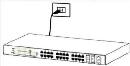
Plugging in the AC Power Cord
Users may now connect the AC power cord into the rear of the switch and to an electrical outlet (preferably one that is grounded and surge protected).
natural_image
Line drawing of a network switch device with ports and an attached cable (no text or symbols)Figure 4 – Plugging the switch into an outlet
Power Failure
As a precaution, the switch should be unplugged in case of power failure. When power is resumed, plug the switch back in.
Chapter 4
Using the Web User Interface
After a successful physical installation, you can configure the Switch, monitor the network status, and display statistics using a web browser.
Supported Web Browsers
The embedded Web-based Management currently supports the following web browsers:
A) Internet Explorer 6 or higher
B) Netscape 8 or higher
C) Mozilla
D) Firefox 1.5/2.0 or higher
Connecting to the Switch
You will need the following equipment to begin the web configuration of your device:
- A PC with a RJ-45 Ethernet connection
- A standard Ethernet cable
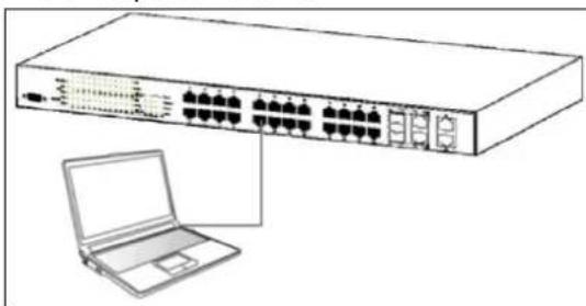
Connect the Ethernet cable to any of the ports on the front panel of the switch and to the Ethernet port on the PC.
natural_image
Line drawing of a network switch device with ports and an external laptop connected to it (no text or symbols present)Figure 5 - Connected to an end node via Ethernet cable
Login Web-based Management
In order to login and configure the switch via an Ethernet connection, the PC must have an IP address in the same subnet as the switch. For example, if the switch has an IP address of 192.168.10.200, the PC should have an IP address of 192.168.10.x (where x is a number between 1 \~ 254), and a subnet mask of 255.255.255.0.
Open the web browser and enter 192.168.10.200 (the factory-default IP address) in the address bar. Then press

Figure 6 - Enter the IP address 192.168.10.200 in the web browser
When the following page appears, enter the user name and password then click Login.

Figure 7 – Enter the IP address 192.168.10.200 in the web browser

The default user name and password are:
User Name Password Privilege
admin admin 15
guest guest123 1
After login successfully, following page will appear.
Device Status

Figure 8 – Web User Interface
The three main areas are the Device Status on top, the Function Tree, and the
Main Configuration Screen.
The Device Status provides a real-time switch port link status.
By choosing different functions in the Function Tree, you can change all the settings in the Main Configuration Screen. The main configuration screen will show the current status of your Switch by clicking the model name on top of the function tree.
To terminate the web management session, click Log Out in the upper right corner.
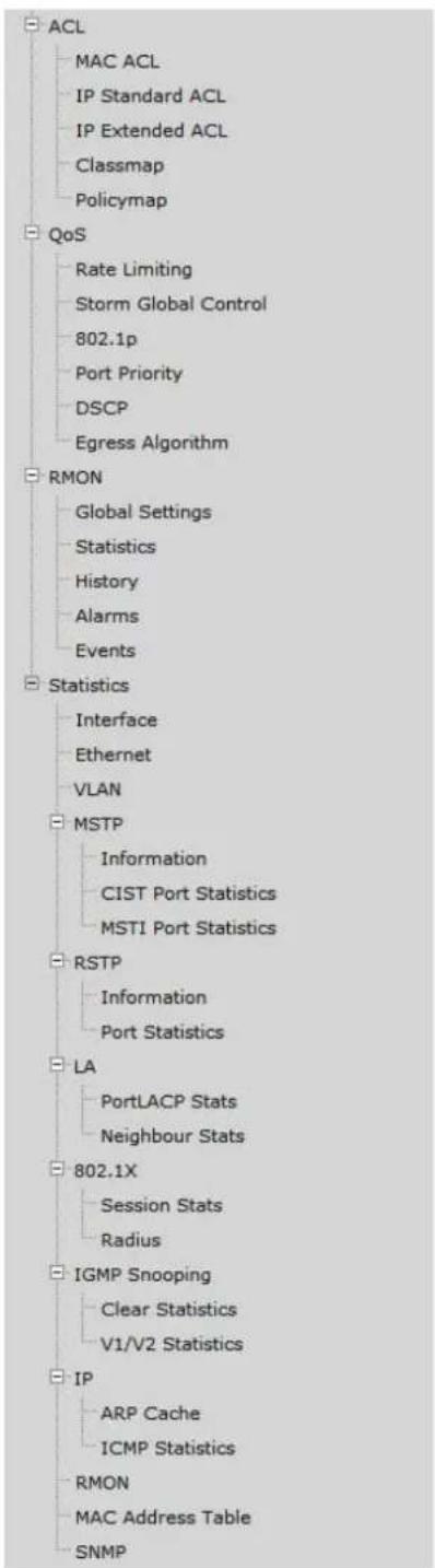
Function Tree
MENU
Home
System
System Information
User Account
Management VLAN
IP Settings
IP Authorized Manager
SNMP
SSH
SSL
System Log
+·SNTP
Configuration
Firmware Upgrade
Reboot

flowchart
graph TD
    A["ACL"] --> B["MAC ACL"]
    A --> C["IP Standard ACL"]
    A --> D["IP Extended ACL"]
    A --> E["Classmap"]
    A --> F["Policymap"]

    G["QoS"] --> H["Rate Limiting"]
    G --> I["Storm Global Control"]
    G --> J["802.1p"]
    G --> K["Port Priority"]
    G --> L["DSCP"]
    G --> M["Egress Algorithm"]

    N["RMON"] --> O["Global Settings"]
    N --> P["Statistics"]
    N --> Q["History"]
    N --> R["Alarms"]
    N --> S["Events"]

    T["Statistics"] --> U["Interface"]
    T --> V["Ethernet"]
    T --> W["VLAN"]

    X["MSTP"] --> Y["Information"]
    X --> Z["CIST Port Statistics"]
    X --> AA["MSTI Port Statistics"]

    AB["RSTP"] --> AC["Information"]
    AB --> AD["Port Statistics"]

    AE["LA"] --> AF["PortLACP Stats"]
    AE --> AG["Neighbour Stats"]

    AH["802.1X"] --> AI["Session Stats"]
    AH --> AJ["Radius"]

    AK["IGMP Snooping"] --> AL["Clear Statistics"]
    AK --> AM["V1/V2 Statistics"]

    AN["IP"] --> AO["ARP Cache"]
    AN --> AP["ICMP Statistics"]

    AQ["RMON"] --> AR["MAC Address Table"]
    AQ --> AS["SNMP"]
Chapter 5
Configuring System Basic
Functions
System Basic Function List
■ System Information
- User Account
- Management VLAN
- Management IP Settings
- IP Authorized Manager
SNMP
SNMP User/Group Table Configuration
SNMP Group Access Table Configuration
SNMP View Table Configuration
SNMP Community Settings
SNMP Host Table
SNMP Engine ID Configuration
- SSH Configuration
- SSL Configuration
- System Log Configuration
SNTP
SNTP and Current Time Settings
SNTP Daylight Saving Time
- Configuration
Save Configuration
Restore Configuration
Erase Configuration
- Firmware Upgrade
- Reboot
System Information
This page is to display and edit relevant system information.
System Information
| Hardware Version | v1.0R | |
| Firmware Version | 1.00.010 | |
| Device Name | TL2-E284 | |
| Device Contact | SysContact | |
| Device Location | SysLocation | |
| Device Up Time | 0 days, 4 hours, 46 mins, 22 seconds | |
| Switch MAC Address | 00:02:e2:84:00:01 | |
| Web Auto Timeout (180-3600 secs) | 600 | |
| CLI Auto Timeout (1-18000 secs) | 1800 | |
Apply
Figure 9 – System > System Information
| Parameter | Description |
| Hardware Version | The hardware version of this device. |
| Firmware Version | The firmware version of the device. |
| Device Name | The name of the device. Default is TL2-E284. |
| Device Contact | The identification information of a contact person. Default is SysContact. |
| Device Location | Entering the device location description. Maximum of 50 characters is allowed and a null string is not accepted. Default is SysLocation. |
| Device Up Time | The time duration since the system has been up and running. |
| Switch MAC Address | The MAC address of the device. |
| Web Auto Timeout (180-3600 secs) | The duration that the device times out when no user activity occurs on the web interface. Default is 600 seconds. |
| CLI Auto Timeout (1-18000 secs) | The duration that the device times out when no user activity occurs on the web interface. Default is 1800 seconds. |
Click Apply to submit the changes.
User Account
This page is to create and display user account information.
User Account
| User Name | |
| Password | |
| Confirm Password | |
| Privilege (1~15) | |
| ADD Reset | |
| select | User Name | New Name | Old Password | New Password | Confirm Password | Privilege |
| admin | admin | 15 | ||||
| guest | guest | 1 |

Figure 10 - System > User Account
| Parameter | Description |
| User Name | Username of an account. |
| Password | Password of an account. |
| Privilege (1-15) | Privilege level that ranges from 1 to 15. 15 are the highest level. |
Click ADD to submit the changes and the Reset button will clear the information. Select and click Delete to remove an existed account. The default accounts are admin (privilege 15) and guest (privilege 1).
Management VLAN
This page is to edit the management VLAN information.
Management VLAN
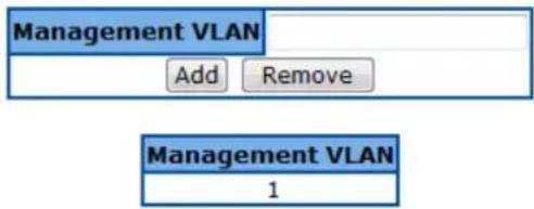
Figure 11 - System > Management VLAN
Parameter
Management VLAN
Description
The VLAN ID of management VLAN. It can be a single VLAN ID from 1 to 4094, a range of VLAN IDs separated by a hyphen (-), or a series of non-continuous numbers divided by a comma (,)
Click ADD to submit the changes and the Remove button will remove an existed VLAN ID.

There has to be at least one management VLAN ID exists.
Management IP Settings
This page is to edit the management IP settings.
Management IP Settings
| IP Address Mode | Manual |
| IP Address | 192.168.10.200 |
| Subnet Mask | 255.255.255.0 |
| Default Gateway | 192.168.10.254 |

Figure 12 - System > IP Settings
Parameter
IP Address Mode
IP Address
Subnet Mask
Default Gateway
Description
To configure the mode that the IP address of default interface is assigned. You can choose Manual or Dynamic. Default is Manual.
IP address of the management interface. Default is 192.168.10.200.
Subnet mask of the management interface. Default is 255.255.255.0.
IP address of default gateway. Default is 192.168.10.254.
Click Apply to submit the changes.
IP Authorized Manager
This page is to set an authorized administrator source IP address, and the services, interfaces, or VLANs that it is allowed to visit.
IP Authorized Manager

Figure 13 - System > IP Authorized Manager
| Parameter | Description |
| IP Address | IP address of authorized manager |
| Subnet Mask | Subnet mask of the authorized IP address |
| Port List (Incoming) | Interface of the authorized administrator is allowed to connect to |
| VLANs Allowed | VLAN ID of the authorized administrator is allowed to connect to. It can be a single VLAN ID from 1 to 4094, a range of VLAN IDs separated by a hyphen (-), or a series of non-continuous numbers divided by a comma (,) |
| Service Allowed | Services that authorized administrator are allowed to access. It includes SNMP, TELNET, HTTP (Web), HTTPS (SSL), SSH services. Select ALL will cover all services. |
Click ADD to submit the changes and the Reset button will clear the information. Select and click Delete to remove an existed account.
SNMP
SNMP User/Group Table Configuration
This page is to configure the SNMP user and group information.
SNMP User/Group Table Configuration

| Select | User Name | Group Name | SNMP Version | Auth-Protocol | Priv-Protocol |
|  | ReadOnly | ReadOnly | v1 | None | None |
|  | ReadOnly | ReadOnly | v2c | None | None |
|  | ReadWrite | ReadWrite | v1 | None | None |
|  | ReadWrite | ReadWrite | v2c | None | None |
| Delete | |||||
Figure 14 - System > SNMP > User/Group Table
| Parameter | Description |
| User Name | SNMP user name |
| Group Name | SNMP group name |
| SNMP Version | Specify the SNMP version to be used, which can be v1, v2c, or v3. Select ‘encrypted’ if the encryption for user authentication is needed. Once the encryption is enabled, then you can set the authentication and privilege algorithm and passwords. |
| Auth-Protocol | Specify the authentication algorithm from MD5 or SHA algorithm, and the password. |
| Priv-Protocol | Specify the privilege encryption algorithm from DES or none, and the password. |
Click ADD to submit the changes and the Reset button will clear the information. Select and click Delete to remove an existed entry.
SNMP Group Access Table Configuration
This page is to configure the access settings of a SNMP group.
SNMP Group Access Table Configuration

| Select | Group Name | Read View | Write View | Notify View | Security Model | Security Level |
|  | ReadOnly | ReadWrite | - | ReadWrite | v1 | NoAuthNoPriv |
|  | ReadOnly | ReadWrite | - | ReadWrite | v2c | NoAuthNoPriv |
|  | ReadWrite | ReadWrite | ReadWrite | ReadWrite | v1 | NoAuthNoPriv |
|  | ReadWrite | ReadWrite | ReadWrite | ReadWrite | v2c | NoAuthNoPriv |
| Delete | ||||||
Figure 15 - System > SNMP > Group Access Table
| Parameter | Description |
| Group Name | SNMP group name |
| Read View Name | The name of group (view) has read privilege and is allowed to access the specified MIB object groups. |
| Write View Name | The name of group (view) has write privilege and is allowed to access the specified MIB object groups. |
| Notify View Name | The name of group (view) can receive SNMP Trap messages and is allowed to access the specified MIB object groups. |
| Security Model | Specify the SNMP version to be used, which can be v1, v2c, or v3. |
| Security Level | Specify if authentication and encryption are needed for SNMP messages.NoAuthNoPriv – Neither authentication or encryption is needed. It is the default setting.AuthNoPriv - Authentication is required for the SNMP messages. It is selectable only when SNMPv3 is specified.AuthPriv – Both authentication and encryption are required for the SNMP messages. It is selectable only when SNMPv3 is specified. |
Click ADD to submit the changes and the Reset button will clear the information. Select and click Delete to remove an existed entry.
SNMP View Table Configuration
This page is to create a SNMP view, which limits the range of MIB objects that a SNMP administrator can access to.
SNMP View Table Configuration

| Select | View Name | Subtree OID | OID Mask | View Type |
| ReadWrite | 1 | 1 | Included | |
| Delete | ||||
Figure 16 - System > SNMP > View Table
| Parameter | Description |
| View Name | SNMP view name |
| Subtree OID | The object ID of MIB tree |
| OID Mask | The mask of OID |
| View Type | included – Includes the object in the list that the SNMP administrator can access.excluded – Excludes the object from the list that the SNMP administrator can access. |
Click ADD to submit the changes and the Reset button will clear the information. Select and click Delete to remove an existed entry.
SNMP Community Settings
This page is to create and edit SNMP community information.
SNMP Community Settings


Figure 17 - System > SNMP > Community Table
| Parameter | Description |
| Community Name | SNMP community name |
| User Name (View Policy) | ReadOnly – The community has read-only privilege.ReadWrite - The community has read write privilege. |
24-Port 10/100Mbps Layer 2 Switch w/ 4 Gigabit Ports and 2 Shared Mini-GBIC Slots
Click ADD to submit the changes and the Reset button will clear the information. Select and click Delete to remove an existed entry.
SNMP Host Table
This page is to create a host that can access the device by SNMP protocol.
SNMP Host Table

| Select | Host Ip Address | SNMP Version | Community Name/User Name |
| Delete |
Figure 18 - System > SNMP > Trap Manager
| Parameter | Description |
| Host IP Address | The IP address of a host that can access to the device by SNMP. |
| SNMP version | Specify the SNMP version to be used, which can be v1, v2c, or v3. |
| Community Name/User Name | The name of SNMP community/user that the host belongs to. |
Click ADD to submit the changes and the Reset button will clear the information. Select and click Delete to remove an existed entry.
SNMP Engine ID Configuration
This page is to configure the SNMP engine identifier of the device.
SNMP Engine ID Configuration

Figure 19 - System > SNMP > Engine ID
| Parameter | Description |
| Engine ID | A string of between 5 and 32 octets expressed in hexadecimal. The default is 8000081c044653. |
Click ADD to submit the changes and the Reset button will clear the information.
SSH Configuration
This page is to configure the SSH server function on the device.
SSH Configuration
| SSH Status | Enable ▼ |
| Version | v2 ▼ |
| Cipher | 3DES-CBC ▼ |
| Authentication | HMAC-SHA1 ▼ |
| Apply | |
Figure 20 - System > SSH
| Parameter | Description |
| SSH Status | Select Enable or Disable to turn on or off the SSH server function. Default is enabled. |
| Version | Specify the SSH version supported.V2 – SSH v2 is supported. This is the default value.V1 & V2 – Both SSH v1 and V2 are supported. |
| Cipher | To specify SSH Cipher algorithm.3DES-CBC - 3DES (Triple Data Encryption Standard) encryption algorithm in CBC (Cipher Blocking Chain). This is the default value.DES-CBC - DES (Data Encryption Standard) in CBC (Cipher Blocking Chain).Both – Both 3DES-CBC and DES-CBC are supported. |
| Authentication | To specify authentication encryption algorithm.HMAC-SHA1 – Hash-based Message Authentication Codes (HMAC) and SHA1 (Secure Hash Algorithm).HMAC-MD5 – Hash-based Message Authentication Codes (HMAC) and MD5 (Message-Digest algorithm 5).Both – Both HMAC-SHA1 and HMAC-MD5 are supported. |
Click Apply to submit the changes.
SSL Configuration
This page is to configure the SSL server function on the device.
SSL Configuration
| SSL Status | Disable |
| Apply |
| Cipher Suits |
| RSA-DES-SHA1 |
| RSA-3DES-SHA1 |
| RSA-EXP1024-DES-SHA1 |
Figure 21 - System > SSL
| Parameter | Description |
| SSL Status | Select Enable or Disable to turn on or off the SSH server function. Default is disabled. The cipher suite includes RSA-DES-SHA1, RSA-3DES-SHA1, and RSA-EXP1024-DES-SHA1 cipher algorithm. |
Click Apply to submit the changes.
System Log Configuration
This page is to configure system log settings.
System Log Configuration
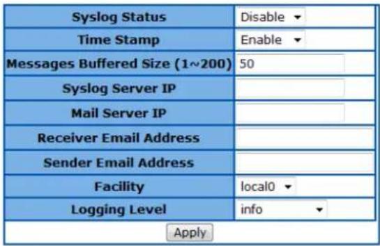
Figure 22 - System > System Log
| Parameter | Description |
| Syslog Status | The status of syslog server function. Default is enabled. |
| Time Stamp | Specifies if time stamp is attached with syslog messages. Default is enabled. |
| Messages Buffered Size (1-200) | The size of internal logging buffer. Default is 50. |
| Syslog Server IP | IP address of the external syslog server |
| Mail Server IP | Specify the IP address of mail server to be used for sending the email alerts messages. |
| Receiver Email Address | The email address of receiver that receives the alert messages. |
| Sender Email Address | The email address of sender that sends out the alert messages. |
| Facility | Specifies the facility that is indicated in the message. Possible values: local0, local1, local2, local3, local4, local5, local6, and local7. Default is Local0. |
| Logging Level | Specifies the severity level of messages. Possible values are:Alert level: action must be taken immediately.Critical level: Critical conditions.Debug level: Debug messages.Emergency level: System is unusable.Error level: Error conditions.Informational level: Informational messages.Notification level: Normal but significant condition.Warning level: Warning conditions.Default is info. |
Click Apply to submit the changes.
SNTP
SNTP and Current Time Settings
This page is to configure SNTP and time settings.
SNTP Settings
| Current Time | 01 Jan 2009 01:02:40 |
| SNTP Status | Disabled ▼ |
| SNTP Poll Interval in Seconds (30~86400) | 30 |
| SNTP Primary Server | 0.0.0.0 |
| SNTP Secondary Server | 0.0.0.0 |
| Time Zone Offset (HH:MM) | GMT + ▼ 00 ▼ 00 ▼ |
| Apply | |
Set Current Time
| Year:Month:Day | 2009 ▼ | January ▼ | 01 ▼ |
| HH:MM:SS | 01 ▼ | 02 ▼ | 40 ▼ |
| Apply | |||
Figure 23 - System > SNTP > Time Settings
| Parameter | Description |
| Current Time | Current system time. |
| SNTP Status | To enable/disable the Simple Network Time Protocol (SNTP) function. Default is disabled. |
| SNTP Poll Interval in Seconds (30-86400) | To set the time interval that SNTP synchronizes the time on SNTP server, and the range is from 30 to 86400 seconds. Default is 30. |
| SNTP Primary Server | To set the primary SNTP server IP address. |
| SNTP Secondary Server | To set the secondary SNTP server IP address. |
| Time Zone Offset (HH:MM) | To specify the difference of current time zone relative to GMT. |
| Year:Month:Day | Specify current date |
| HH:MM:SS | Specify current system time. |
Click Apply to submit the changes.
SNTP Daylight Saving Time
This page is to configure the daylight saving time function of system time setting.
SNTP Daylight Saving Configuration
| Daylight Saving Time Status | Disabled ▼ | |||
| Daylight Saving Time: | ||||
| From (Month:Day:HH:MM) | January ▼ | 01 ▼ | 00 ▼ | 00 ▼ |
| To (Month:Day:HH:MM) | January ▼ | 01 ▼ | 00 ▼ | 00 ▼ |
| Apply | ||||
Figure 24 – System > SNTP > Daylight Saving Time
| Parameter | Description |
| Daylight Saving Time Status | To enable/disable the DST function. Default isdisabled. |
| Daylight Saving Time:From(Month:Day:HH:MM) | Specify the DST period in month:day:hour:minute. |
To
(Month:Day:HH:MM)
Click Apply to submit the changes.
Configuration
Save Configuration
This page is used to save the running configuration.
Save Configuration

Configuration Save was successful
Figure 25 - System > Configuration > Save
Parameter
Save option
Description
Options to save the running configuration:
Flash Save: Save to the device's flash memory with a designated file name. Saving the configuration to flash will back up the current configuration in the device's internal memory to be restored later if necessary but will not set the configuration as active after a device reboot or power cycle.
Remote Save: Save to the remote TFTP server with a designated IP address and file name. This will back up the configuration to an external location.
Startup-Config Save: Save to the device's startup configuration.
Note: This will set the current configuration as the active configuration after a device reboot or power cycle.
IP Address
File Name
IP address of the remote TFTP server.
Specify the filename of the configuration to be saved.
Click Apply to submit the changes and the Reset button will clear the information.
Restore Configuration
This page is used to restore startup configuration from another configuration file in flash memory.
Restore Configuration

Figure 26 - System > Configuration > Restore
| Parameter | Description |
| Restore Option | Options to restore the startup configuration:No Restore: Applying this option will reset the NV-RAM to default settings.Note: This will only reset the settings in NV-RAM, not the entire device configuration. After rebooting, only the default parameters in NV-RAM will be reset to defaults. Requires a manual device reboot for changes to take effect.Please reference the default NV-RAM parameters below.Default IP Address : 192.168.10.200Default Subnet Mask: 255.255.255.0Default IP Address Config Mode: ManualDefault IP Address Allocation Protocol : DHCPDefault Interface Name: Fa0/1Default RM Interface Name: NONEConfig Restore Option: No restoreConfig Save Option: Startup saveConfig Save IP Address: 0.0.0.0Config Save Filename: iss.confConfig Restore Filename: iss.confPIM Mode: Sparse ModeIGS Forwarding Mode: MAC basedCLI Serial Console: YesSNMP EngineID: 80.00.08.1c.04.46.53SNMP Engine Boots: 1Default VLAN Identifier: 1 |
| Flash Restore:Restore from a previously backed up configuration file in the device's flash memory to the startup-config. Note: After restoring configuration, requires a manual device reboot for changes to take effect. | |
| File Name | Specify the file name of the configuration to be restored. |
File Name
Click Apply to submit the changes and the Reset button will clear the information.
Erase Configuration
This page is used to reset the startup configuration, NV-RAM or the configuration file in flash to default value.
Erase Configuration

Figure 27 - System > Configuration > Erase
| Parameter | Description |
| Erase option | Specify the configuration to be reset:Erase Nvram: Reset the NV-RAM to default settings and reset all previously saved configuration files to default that were stored flash memory.Note: This will only reset the settings in NV-RAM, not the entire device configuration. After rebooting, only the default parameters in NV-RAM will be |
reset to defaults. Requires a manual device reboot for changes to take effect. Please reference the default NV-RAM parameters below.
- Default IP Address : 192.168.10.200
- Default Subnet Mask: 255.255.255.0
- Default IP Address Config Mode: Manual
- Default IP Address Allocation Protocol : DHCP
- Default Interface Name: Fa0/1
- Default RM Interface Name: NONE
- Config Restore Option: No restore
- Config Save Option: Startup save
- Config Save IP Address: 0.0.0.0
- Config Save Filename: iss.conf
- Config Restore Filename: iss.conf
- PIM Mode: Sparse Mode
• IGS Forwarding Mode: MAC based
• CLI Serial Console: Yes
• SNMP EngineID: 80.00.08.1c.04.46.53
• SNMP Engine Boots: 1 - Default VLAN Identifier: 1
Erase Startup-Config: Reset the all device configuration to default settings.
Note: This will reset the startup device configuration to default. Any previously saved configuration files in flash memory will NOT be deleted or erased. After a device reboot or power cycle, the default device configuration will be loaded to the device. Requires a manual device reboot for changes to take effect.
Erase Flash File: Reset the specified configuration file in the device's flash memory to default settings.
Note: This will not reset the device's active configuration.
File Name
Specify the file name of the local configuration file.
Click Apply to submit the changes and the Reset button will clear the information.
Firmware Upgrade
Firmware Upgrade

Parameter
HTTP
Firmware Upgrade
TFTP
Firmware Upgrade
Description
Click Browse to locate the firmware file on the local hard drive and select it.
TFTP Server IP Address: Specify the IP address of the TFTP server.
TFTP firmware file name: Specify the filename of the firmware file.
24-Port 10/100Mbps Layer 2 Switch w/ 4 Gigabit Ports and 2 Shared Mini-GBIC Slots
Click Upgrade to upgrade the device firmware.
Reboot
This page is to reboot the system.
Reboot
Are you sure you want to proceed with the system reboot?
If yes, click the Reboot button.
Reboot
Figure 28 - System > Reboot
Click Reboot to warm start the device.

If the Switch reboots without write the running configurations, the last configuration wrote in NV-RAM will be loaded.
Chapter 6
Configuring Layer 2 Management
Functions
Layer 2 Management Function List
- Port Manager
Port Basic Settings
Port Monitoring
Port Control
■ VLAN
VLAN Basic Information
VLAN Port Settings
Static VLAN Configuration
- Dynamic VLAN
Dynamic VLAN Global Configuration
Dynamic VLAN Port Configuration
GARP Timers Configuration
■ MSTP
MSTP Global Configuration
MSTP Timers Configuration
CIST Settings
MSTP VLAN Mapping
MSTP Port Settings
MSTP CIST Port Status
- RS
RSTP Global Configuration
RSTP Configuration
RSTP Port Status Configuration
RSTP Port Status
• LA
LA Basic Settings
PortChannel Interface Basic Settings
LA Port Channel Settings
LA Port Settings
LA Port StateMachine Information
LA Load Balancing Policy
802.1X
802.1X Basic Settings
802.1X Port Settings
802.1X Timer Configuration
802.1X Local Authentication Server Configuration
RADIUS Server Configuration
- IGMP Snooping
IGMP Snooping Configuration
IGMP Snooping Timer Configuration
IGMP Snooping Interface Configuration
IGMP Snooping VLAN Router Ports
MAC Based Multicast Forwarding Table
- Static MAC Entries
Static MAC Address Configuration
Static Multicast Address Configuration
Port Security Settings
Port Manager
Port Basic Settings
This page is to configure basic settings of switch ports.
Port Basic Settings
1-12 | 13-24 | 25-28 |
| Select | Port | Link Status | Admin State | MTU (90~1522) bytes | Link Up/Down Trap |
| 1 | Up ▼ | 1522 | Enabled ▼ | ||
| 2 | Up ▼ | 1522 | Enabled ▼ | ||
| 3 | Up ▼ | 1522 | Enabled ▼ | ||
| 4 | Up ▼ | 1522 | Enabled ▼ | ||
| 5 | Up ▼ | 1522 | Enabled ▼ | ||
| 6 | Up ▼ | 1522 | Enabled ▼ | ||
| 7 | Up ▼ | 1522 | Enabled ▼ | ||
| 8 | Up ▼ | 1522 | Enabled ▼ | ||
| 9 | Up ▼ | 1522 | Enabled ▼ | ||
| 10 | Up ▼ | 1522 | Enabled ▼ | ||
| 11 | Up ▼ | 1522 | Enabled ▼ | ||
| 12 | Up ▼ | 1522 | Enabled ▼ |
Apply
Figure 29 - Layer2 Management > Port Manager > Basic Settings
| Parameter | Description |
| Port | Specify the switch port to be configured. |
| Link State | Display the physical connection states of the port. |
| Admin State | Specify the administrative status of the port. Default is enabled. |
| MTU (90-1522) bytes | To setup the Maximum Transmission Unit (MTU) frame size of the interface, and the range is from 90 to 1522 bytes. Default is 1500. |
| Link Up/Down Trap | To enable/disable the link up/down trap information delivery. Default is enabled. |
Click Apply to submit the changes.
Port Monitoring
This page is to configure the port monitoring function on the device.
Port Monitoring
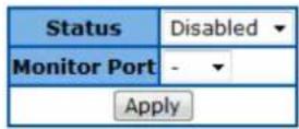
1-12 | 13-24 | 25-28 |
| Select | Port | Receive Monitoring | Transmit Monitoring |
| 1 | Disabled ▼ | Disabled ▼ | |
| 2 | Disabled ▼ | Disabled ▼ | |
| 3 | Disabled ▼ | Disabled ▼ | |
| 4 | Disabled ▼ | Disabled ▼ | |
| 5 | Disabled ▼ | Disabled ▼ | |
| 6 | Disabled ▼ | Disabled ▼ | |
| 7 | Disabled ▼ | Disabled ▼ | |
| 8 | Disabled ▼ | Disabled ▼ | |
| 9 | Disabled ▼ | Disabled ▼ | |
| 10 | Disabled ▼ | Disabled ▼ | |
| 11 | Disabled ▼ | Disabled ▼ | |
| 12 | Disabled ▼ | Disabled ▼ |
Apply
Figure 30 - Layer2 Management > Port Manager > Port Monitoring
| Parameter | Description |
| Status | To enable/disable the port monitoring session on the device. Default is disabled. |
| Monitoring Port | Specify the source port of the mirror session. |
| Port | Specify the destination port of the mirror session. |
| Receive Monitoring | Monitoring the traffic received from the source port. |
| Transmit Monitoring | Monitoring the traffic transmitted from the source port. |
Click Apply to submit the changes.
Port Control
This page is to configure the control parameters of interface.
Port Control
1-12 | 13-24 | 25-28 |
| Select | Port | Mode | Duplex | Speed | FlowControl Admin Status | FlowControl Oper Status | MDI/MDIX | Media Type |
| 1 | Auto ▼ | Full ▼ | 100MBPS ▼ | Disabled ▼ | Disabled ▼ | AUTO ▼ | Copper ▼ | |
| 2 | Auto ▼ | Full ▼ | 100MBPS ▼ | Disabled ▼ | Disabled ▼ | AUTO ▼ | Copper ▼ | |
| 3 | Auto ▼ | Full ▼ | 100MBPS ▼ | Disabled ▼ | Disabled ▼ | AUTO ▼ | Copper ▼ | |
| 4 | Auto ▼ | Full ▼ | 100MBPS ▼ | Disabled ▼ | Disabled ▼ | AUTO ▼ | Copper ▼ | |
| 5 | Auto ▼ | Full ▼ | 100MBPS ▼ | Disabled ▼ | Disabled ▼ | AUTO ▼ | Copper ▼ | |
| 6 | Auto ▼ | Full ▼ | 100MBPS ▼ | Disabled ▼ | Disabled ▼ | AUTO ▼ | Copper ▼ | |
| 7 | Auto ▼ | Full ▼ | 100MBPS ▼ | Disabled ▼ | Disabled ▼ | AUTO ▼ | Copper ▼ | |
| 8 | Auto ▼ | Full ▼ | 100MBPS ▼ | Disabled ▼ | Disabled ▼ | AUTO ▼ | Copper ▼ | |
| 9 | Auto ▼ | Full ▼ | 100MBPS ▼ | Disabled ▼ | Disabled ▼ | AUTO ▼ | Copper ▼ | |
| 10 | Auto ▼ | Full ▼ | 100MBPS ▼ | Disabled ▼ | Disabled ▼ | AUTO ▼ | Copper ▼ | |
| 11 | Auto ▼ | Full ▼ | 100MBPS ▼ | Disabled ▼ | Disabled ▼ | AUTO ▼ | Copper ▼ | |
| 12 | Auto ▼ | Full ▼ | 100MBPS ▼ | Disabled ▼ | Disabled ▼ | AUTO ▼ | Copper ▼ |
Apply
Figure 31 – Layer2 Management > Port Manager > Port Control
| Parameter | Description |
| Port | Specify the switch port to be configured. |
| Mode | To enable/disable auto-negotiation function on ports. Default is Auto. |
| Duplex | To set the port duplex mode. Possible values are:Full: Port runs at full duplex mode.Half: Port runs at half duplex mode. |
| Speed | To set the port speed. Possible values are:10MBPS: Port runs at 10Mbps.100MBPS: Port runs at 100Mbps.1GB: Port runs at 1000Mbps.Only port 25-28 can run at 1000Mbps. |
| FlowControl Admin Status | To enable/disable 802.3x flow control on ports. Default is Disabled. |
| FlowControl Oper Status | To display the flow control operation status. |
| MDI/MDIX | To set MDI or MDIX mode for ports. Possible values are:Auto: Port performs the auto MDI/MDIX function.MDI: Port fixed at MDI mode.MDIXB: Port fixed at MDIX mode.Default is Auto. |
Click Apply to submit the changes.

The port speed and duplex settings can only be configured when auto-negotiation disabled.
VLAN
VLAN Basic Information
This page is to configure the basic settings of virtual local area network (VLAN) on the device.
VLAN Basic Information
| VLAN Mode | 802.1Q VLAN |
| Maximum VLAN ID | 4094 |
| Maximum Supported VLANs | 256 |
| Number of VLANs in the System | 1 |
Apply
Figure 32 – Layer2 Management > VLAN > Basic Information
| Parameter | Description |
| VLAN Mode | Choose from 802.1Q VLAN or Asymmetric VLAN modes. Default is 802.1Q VLAN. |
| Maximum VLAN ID | Display the maximum VLAN ID can be configured. Default is 4094. |
| Maximum Supported VLANs | Display the maximum VLANs can be supported. Default is 256. |
| Number of VLANs in the System | Display the current VLAN number in the system. Default is 1. |
Click Apply to submit the changes.
VLAN Port Settings
This page is to configure VLAN setting on physical port interfaces.
VLAN Port Settings
1-12 | 13-24 | 25-28 |
| Select | Port | PVID | Acceptable Frame Types | Ingress Filtering |
| 1 | 1 | All | Enabled | |
| 2 | 1 | All | Enabled | |
| 3 | 1 | All | Enabled | |
| 4 | 1 | All | Enabled | |
| 5 | 1 | All | Enabled | |
| 6 | 1 | All | Enabled | |
| 7 | 1 | All | Enabled | |
| 8 | 1 | All | Enabled | |
| 9 | 1 | All | Enabled | |
| 10 | 1 | All | Enabled | |
| 11 | 1 | All | Enabled | |
| 12 | 1 | All | Enabled |
Figure 33 - Layer2 Management > VLAN > Port Settings
| Parameter | Description |
| Port | Specifies the switch port which is to be configured. |
| PVID | To set the port VLAN ID of the port, all ingress untagged or priority tagged packet from this port will be assign to this VLAN. The range is from 1 to 4094. |
| Acceptable Frame Types | To configure the acceptable frame type of a port.All: Accepts all kinds of frames.Tagged: Accepts only tagged framesUnTagged and Priority Tagged: Accepts only untagged frames and frames with priority tag.Default is All. |
| Ingress Filtering | To enable/disable the filter of ingress packets not with the same VLAN tag as the VLAN membership of the port. Default is Enabled. |
In the left-hand Select column, check all of the ports modified and click Apply to submit the changes.
Static VLAN Configuration
This page is to set up the static VLAN configuration.
Static VLAN Configuration
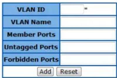
| Select | VLAN ID | VLAN Name | Member Ports | Untagged Ports | Forbidden Ports |
|  | 1 | 1-28 | 1-28 | ||
| ApplyDelete | |||||
Figure 34 – Layer2 Management > VLAN > Static VLANs
| Parameter | Description |
| VLAN ID | Specify the VLAN ID to be created. |
| VLAN Name | Specify the name of VLAN. |
| Member Ports | Specify the ports to apply the VLAN membership. |
| Untagged Ports | Specify the ports to be untagged interfaces. |
| Forbidden Ports | Specify the ports to be forbidden interfaces. |
Click Apply to submit the changes and the Reset button will clear the information. Click Delete will remove an existed VLAN.

There has to be at least one VLAN in the system.
Dynamic VLAN
Dynamic VLAN Global Configuration
This page is to set the global dynamic VLAN configuration.
Dynamic Vlan Global Configuration

Apply
Note : To Shutdown GARP, Dynamic Vlan Should Be Disabled.
Figure 35 – Layer2 Management > Dynamic VLAN > Dynamic VLAN Global Configuration
| Parameter | Description |
| Garp System Control | Choose Start to enable GARP function, and Shutdown to disable it. It is needed for using dynamic VLAN function. Default is Start. |
| Dynamic VLAN Status | To set the status of dynamic VLAN function from Enabled or Disabled. Default is Disabled. |
Click Apply to submit the changes.
Dynamic VLAN Port Configuration
This page is to configure dynamic VLAN settings on switch ports.
Dynamic Vlan Port Configuration
1-12 | 13-24 | 25-28 |
| Select | Port | Dynamic Vlan Status | Restricted VLAN Registration |
| ○ | 1 | Enabled ▼ | Disabled ▼ |
| ○ | 2 | Enabled ▼ | Disabled ▼ |
| ○ | 3 | Enabled ▼ | Disabled ▼ |
| ○ | 4 | Enabled ▼ | Disabled ▼ |
| ○ | 5 | Enabled ▼ | Disabled ▼ |
| ○ | 6 | Enabled ▼ | Disabled ▼ |
| ○ | 7 | Enabled ▼ | Disabled ▼ |
| ○ | 8 | Enabled ▼ | Disabled ▼ |
| ○ | 9 | Enabled ▼ | Disabled ▼ |
| ○ | 10 | Enabled ▼ | Disabled ▼ |
| ○ | 11 | Enabled ▼ | Disabled ▼ |
| ○ | 12 | Enabled ▼ | Disabled ▼ |
Apply
Figure 36 - Layer2 Management > Dynamic VLAN > Port Settings
| Parameter | Description |
| Port | Specify the switch port to be configured. |
| Dynamic VLAN Status | To set the status of dynamic VLAN function from Enabled or Disabled. |
| Restricted VLAN Registration | To enable/disable the restricted VLAN on an interface. |
24-Port 10/100Mbps Layer 2 Switch w/ 4 Gigabit Ports and 2 Shared Mini-GBIC Slots
Click Apply to submit the changes.
GARP Timers Configuration
This page is to set the GARP timers on an interface.
Garp Timers Configuration
1-12 | 13-24 | 25-28 |
| Select | Port No | GarpJoinTime (10 ~ 2^30-14) (msecs) | GarpLeaveTime (30 ~ 2^31-18) (msecs) | GarpLeaveAllTime (40 ~ 2^31-8) (msecs) |
| ◎ | 1 | 200 | 600 | 10000 |
| ◎ | 2 | 200 | 600 | 10000 |
| ◎ | 3 | 200 | 600 | 10000 |
| ◎ | 4 | 200 | 600 | 10000 |
| ◎ | 5 | 200 | 600 | 10000 |
| ◎ | 6 | 200 | 600 | 10000 |
| ◎ | 7 | 200 | 600 | 10000 |
| ◎ | 8 | 200 | 600 | 10000 |
| ◎ | 9 | 200 | 600 | 10000 |
| ◎ | 10 | 200 | 600 | 10000 |
| ◎ | 11 | 200 | 600 | 10000 |
| ◎ | 12 | 200 | 600 | 10000 |
Apply
Note : Leave Timer must be greater than 2 times Join Timer and Leaveall Timer must be greater than Leave Timer.
Figure 37 - Layer2 Management > Dynamic VLAN > Port Settings
| Parameter | Description |
| Port No | Specify the switch port to be configured. |
| GarpJoinTime (10 ~ 2^30-14)(msecs) | Specify the join time of GARP. Default is 20 milliseconds. |
| GarpLeaveTime (30 ~ 2^31-18)(msecs) | Specify the leave time of GARP. Default is 60 milliseconds. |
| GarpLeaveAllTime (40 ~ 2^31-8)(msecs) | Specify the leave all time of GARP. Default is 100 milliseconds. |
Click Apply to submit the changes.
MSTP
MSTP Global Configuration
This page is to configure the MSTP global settings of the Switch.
Global Configuration
| System Control | MSTP Status | Maximum MST Instances | Bridge Priority | Protocol Version | Region Name | Region Version | Dynamic Path Cost Calculation |
| Shutdown ▼ | Disabled ▼ | 0 | 0 | MSTP ▼ | 0 | True ▼ |
Apply
Note : To enable MSTP Functionality, RSTP should be disabled.
Bridge Priority must be in increments of 4096 and can be upto 61440. Allowed values are: 0 4096 8192 12288 16384 20480 24576 28672 32768 36864 40960 45056 49152 53248 57344 61440
Figure 38 - Layer2 Management > MSTP > Global Configuration
| Parameter | Description |
| System Control | To activate or shutdown the MSTP function. Select Start to activate the MSTP function, Shutdown to shutdown MSTP function. |
| MSTP Status | To enable or disable the MSTP. Select Enabled to enable the MSTP function, Disabled to disable the MSTP function. |
| Maximum MSTP Instances | Specify the maximum number of MSTP instance allowed. The possible number is 1-64. Default is 64. |
| Bridge Priority | Specify the bridge priority of spanning tree. Default is 32768. |
| Protocol Version | Select the spanning tree compatibility version. The possible options are STP, RSTP and MSTP. Default is RSTP. |
| Region Name | Specify the region name of MST. |
| Region Version | Specify the MST region revision. The possible numbers are 0~65535, default is 0. |
| Dynamic Path Cost Calculation | Select the path cost calculation mode of spanning tree. Select True to enable dynamic path cost according to the port speed, False to disable it. Default if False. |
Click Apply to submit the changes.

- RSTP function must be shutdown before activate MSTP.
- MSTP status must be enabled before configure other MSTP details.
MSTP Timers Configuration
This page is to configure the MSTP timers of the Switch.
Timers Configuration
| Maximum Hop Count | Max Age | Forward Delay | Transmit Hold Count |
| 0 | 0 | 0 | 6 |
Apply
Figure 39 - Layer2 Management > MSTP > Timers Configuration
| Parameter | Description |
| Maximum Hop Count | Specify the maximum hops permitted in MST. Possible value is 6-40. Default is 20. |
| Max Age | Specify the maximum age in second for STP information learned from the network on any port before it is discarded. The possible value is 6-40. Defaultis 20. |
| Forward Delay | Specify the time period in second that a port changes the STP state from blocking to forwarding. The possible value is 4-30. Default is 15. |
| Transmit Hold Count | Specify the hold counter to limit maximum transmission rate of the Switch. Default is 3. |
| Hello Time | Specify the time interval in second for a root bridge broadcasts the hello packets to other switches. Possible value is 1-2. Default is 2. |
CIST Settings
This page is to configure the port related MSTP settings.
CIST Settings
1-12 | 13-24 | 25-28 |
| Select | Port | Path Cost | Priority | PointToPoint Status | Edge Port | MSTP Status | Protocol Migration | Hello Time | AutoEdge Status | Restricted Role | Restricted TCN |
| 1 | 200000 | 128 | Auto | False | Enable | ▼ | 2 | True | False | False | |
| 2 | 200000 | 128 | Auto | False | Enable | ▼ | 2 | True | False | False | |
| 3 | 200000 | 128 | Auto | False | Enable | ▼ | 2 | True | False | False | |
| 4 | 200000 | 128 | Auto | False | Enable | ▼ | 2 | True | False | False | |
| 5 | 200000 | 128 | Auto | False | Enable | ▼ | 2 | True | False | False | |
| 6 | 200000 | 128 | Auto | False | Enable | ▼ | 2 | True | False | False | |
| 7 | 200000 | 128 | Auto | False | Enable | ▼ | 2 | True | False | False | |
| 8 | 200000 | 128 | Auto | False | Enable | ▼ | 2 | True | False | False | |
| 9 | 200000 | 128 | Auto | False | Enable | ▼ | 2 | True | False | False | |
| 10 | 200000 | 128 | Auto | False | Enable | ▼ | 2 | True | False | False | |
| 11 | 200000 | 128 | Auto | False | Enable | ▼ | 2 | True | False | False | |
| 12 | 200000 | 128 | Auto | False | Enable | ▼ | 2 | True | False | False |
Apply
Figure 40 - Layer2 Management > MSTP > Port Configuration
| Parameter | Description |
| Select | Select a port to apply the configuration changes. |
| Port | Port ID. |
| Path Cost | Specify the path cost of the port. Possible value is 0-200000000. Default 200000000 |
| Priority | Specify the spanning tree port priority. Possible value is 0-240. Default is 128. |
| Point to Point Status | Specify the link type of this port. ForceTrue means link type is point to point;ForceFalse means it is shared; Auto means the decision will made automatically. Default is auto. |
| Edge Port | Specify if this port is edge port or not. Select True to enable the portfast function, False to disable it. Default is false. |
| MSTP Status | To enable or disable the MSTP on this port. Select Enable to enable MSTP on this port, Disable to disable it. Default is enabled. |
| Protocol Migration | To control if the port will migrate among MSTP, RSTP and STP automatically if another switch runs different protocol. Select True to enable the protocol migration function, False to disable it. Default is False. |
| Hello Time | Specify the hello time of this port. Possible value is 1-2. Default is 2. |
| AutoEdge Status | To enable or disable the auto edge detection of this port. Select True to enable the auto edge function, False to disable it. Default true. |
| Restricted Role | To enable or disable the root guard function to prevent the port becoming a root port. Select True to enable the root guard function, False to disable it. Default is false. |
| Restricted TCN | To enable the topology change guard function to prevent the topology change caused by this port. Select True to enable the topology change guard |
function, False to disable it. Default is false.
Click Apply to submit the changes.
MSTP VLAN Mapping
This page is to configure the MST Instance and VLAN mapping.
VLAN Mapping


Figure 41 - Layer2 Management > MSTP > VLAN Mapping
| Parameter | Description |
| MSTP Instance ID | Specify which MST instance to be mapped. |
| Add VLAN | Add a VLAN to the map list of this MST instance. |
| Delete VLAN | Delete a VLAN from the map list of this MST instance. |
Click Add to submit the changes, Reset to clear the value.
MSTP Port Settings
This page is to configure the port related MSTP settings.
Port Settings
| Select | Port | MSTPInstance ID | Port State | Priority | Cost |
Figure 42 - Layer2 Management > MSTP > Port Settings
| Parameter | Description |
| Select | Select a port to apply the changes. |
| Port | Port ID. |
| MSTP Instance ID | Specify the MST instance IP of this port. |
| Port State | Specify the current state of this port. |
| Priority | Specify the spanning tree port priority. Possible value is 0-240. Default is 128. |
| Cost | Specify the path cost of the port. Possible value is 0-200000000. Default 200000000 |
MSTP CIST Port Status
To display the current MSTP CIST port status.
MSTP CIST Port Status
1-12 | 13-24 | 25-28 |
| Port | Designated Root | Root Priority | Designated Bridge | Designated Port | Designated Cost | Regional Root | Regional Root Priority | Regional Path Cost | Type | Role | Port State |
| 1 | 00:00:00:00:00:00:00:00 | 0 | 00:00:00:00:00:00:00:00:00 | 00:00 | 0 | 00:00:00:00:00:00:00:00:00 | 0 | 0 | SharedLan | Disabled | Disabled |
| 2 | 00:00:00:00:00:00:00:00:00 | 0 | 00:00:00:00:00:00:00:00:00 | 00:00 | 0 | 00:00:00:00:00:00:00:00:00 | 0 | 0 | SharedLan | Disabled | DisabledLan |
| 3 | 00:00:00:00:00:00:00:00:00 | 0 | 00:00:00:00:00:00:00:00:00 | 00:00 | 0 | 00:00:00:00:00:00:00:00:00 | 0 | 0 | SharedLanLan | Disabled | Disabled |
| 4 | 00:00:00:00:00:00:00:00:00 | 0 | 00:00:00:00:00:00:00:00:00 | 00:00 | 0 | 00:00:00:00:00:00:00:00:00 | 0 | 0 | SharedLan Llan | Disabled | Disabled |
| 5 | 00:00:00:00:00:00:00:00:00 | 0 | 00:00:00:00:00:00:00:00:00 | 00:00 | 0 | 00:00:00:00:00:00:00:00:00 | 0 | 0 | PointtoPoint | Disabled | Disabled |
| 6 | 00:00:00:00:00:00:00:00:00 | 0 | 00:00:00:00:00:00:00:00:00 | 00:00 | 0 | 00:00:00:00:00:00:00:00:00 | 0 | 0 | SharedLan Lan | Disabled | Disabled |
| 7 | 00:00:00:00:00:00:00:00:00 | 0 | 00:00:00:00:00:00:00:00:00 | 00:00 | 0 | 00:00:00:00:00:00:00:00:00 | 0 | 0 | SharedLan Lin | Disabled | Disabled |
| 8 | 00:00:00:00:00:00:00:00:00 | 0 | 00:00:00:00:00:00:00:00:00 | 00:00 | 0 | 00:00:00:00:00:00:00:00:00 | 0 | 0 | SharedLan .Llan | Disabled | Disabled |
| 9 | 00:00:00:00:00:00:00:00:00 | 0 | 00:00:00:00:00:00:00:00:00 | 00:00 | 0 | 00:00:00:00:00:00:00:00:00 | 0 | 0 | SharedLan. | Disabled | Disabled |
| 10 | 00:00:00:00:00:00:00:00:00 | 0 | 00:00:00:00:00:00:00:00:00 | 00:00 | 0 | 00:00:00:00:00:00:00:00:00 | 0 | 0 | SharedLan 1lan | Disabled | Disabled |
| 11 | 00:00:00:00:00:00:00:00:00 | 0 | 00:00:00:00:00:00:00:00:00 | 00:00 | 0 | 00:00:00:00:00:00:00:00:00 | 0 | 0 | SharedLan.Llan | Disabled | Disabled |
| 12 | 00:00:00:00:00:00:00:00:00 | 0 | 00:00:00:00:00:00:00:00:00 | 00:00 | 0 | 00:00:00:00:00:00:00:00:00 | 0 | 0 | SharedLlan .Llan | Disabled | Disabled |
Figure 43 – Layer2 Management > MSTP > CIST Port Status
Click 1-12, 13-24, 25-28 to display the statistics for corresponding ports.
RSTP
RSTP Global Configuration
This page is to configure the RSTP global settings.
Global Configuration
| System Control | Status | Dynamic Path Cost Calculation |
| Start▼ | Disabled▼ | True▼ |
Apply
Note : To enable RSTP Functionality, MSTP should be disabled.
Figure 44 – Layer2 Management > RSTP > Global Settings
| Parameter | Description |
| System Control | To activate or shutdown the RSTP function. Select Start to activate the MSTP function, Shutdown to shutdown MSTP function. |
| Status | To enable or disable the MSTP. Select Enabled to enable the MSTP function, Disabled to disable it. Default is disabled. |
| Dynamic Path Cost Calculation | Select the path cost calculation mode of spanning tree. Select True to enable dynamic path cost according to the port speed, False to disable it. Default if False. |
Click Apply to submit the changes.

- MSTP function must be shutdown before activate RSTP.
- RSTP status must be enabled before configure other RSTP details.
RSTP Configuration
This page is to configure the timers and other details of RSTP functions.
RSTP Configuration
| Priority | Version | Tx Hold Count | Max Age | Hello Time | Forward Delay |
| 32768 | RSTP Compatible ▼ | 6 | 20 | 2 | 15 |
Apply
Bridge Priority must be in increments of 4096 and can be upto 61440. Allowed values are:
0 4096 8192 12288 16384 20480 24576 28672 32768 36864 40960 45056 49152 53248 57344 61440
Figure 45 – Layer2 Management > RSTP > Basic Settings
| Parameter | Description |
| Priority | Specify the bridge priority of spanning tree. Default is 32768. |
| Version | Select the spanning tree compatibility version. The possible options are STP Compatible or RSTP Compatible. Default is RSTP Compatible. |
| Tx Hold Count | Specify the hold counter to limit maximum transmission rate of the Switch. Default is 6. |
| Max Age | Specify the maximum age in second for STP information learned from the network on any port before it is discarded. The possible value is 6-40. Default is 20. |
| Help Time | Specify the time interval in second for a root bridge broadcasts the hello packets to other switches. Possible value is 1-2. Default is 2. |
| Forward Delay | Specify the time period in second that a port changes the STP state from blocking to forwarding. The possible value is 4-30. Default is 15. |
Click Apply to submit the changes.
RSTP Port Status Configuration
This page is to configure the port related RSTP settings
Port Status Configuration
1-12 | 13-24 | 25-28 |
| Select | Port | Port Role | Port Priority | RSTP Status | Path Cost | Protocol Migration | AdminEdge Port | Admin Point To Point | Auto Edge Detection | Restricted Role | Restricted TCN |
| ◯ | 1 | Disabled | 128 | Enable ▼ | 200000 | False ▼ | False ▼ | Auto ▼ | True ▼ | False ▼ | False ▼ |
| ◯ | 2 | Disabled | 128 | Enable ▼ | 200000 | False ▼ | False ▼ | Auto ▼ | True ▼ | False ▼ | False ▼ |
| ◯ | 3 | Disabled | 128 | Enable ▼ | 200000 | False ▼ | False ▼ | Auto ▼ | True ▼ | False ▼ | False ▼ |
| ◯ | 4 | Disabled | 128 | Enable ▼ | 200000 | False ▼ | False ▼ | Auto ▼ | True ▼ | False ▼ | False ▼ |
| ◯ | 5 | Designate | 128 | Enable ▼ | 200000 | False ▼ | False ▼ | Auto ▼ | True ▼ | False ▼ | False ▼ |
| ◯ | 6 | Disabled | 128 | Enable ▼ | 200000 | False ▼ | False ▼ | Auto ▼ | True ▼ | False ▼ | False ▼ |
| ◯ | 7 | Disabled | 128 | Enable ▼ | 200000 | False ▼ | False ▼ | Auto ▼ | True ▼ | False ▼ | False ▼ |
| ◯ | 8 | Disabled | 128 | Enable ▼ | 200000 | False ▼ | False ▼ | Auto ▼ | True ▼ | False ▼ | False ▼ |
| ◯ | 9 | Disabled | 128 | Enable ▼ | 200000 | False ▼ | False ▼ | Auto ▼ | True ▼ | False ▼ | False ▼ |
| ◯ | 10 | Disabled | 128 | Enable ▼ | 200000 | False ▼ | False ▼ | Auto ▼ | True ▼ | False ▼ | False ▼ |
| ◯ | 11 | Disabled | 128 | Enable ▼ | 200000 | False ▼ | False ▼ | Auto ▼ | True ▼ | False ▼ | False ▼ |
| ◯ | 12 | Disabled | 128 | Enable ▼ | 200000 | False ▼ | False ▼ | Auto ▼ | True ▼ | False ▼ | False ▼ |
Apply
Note: Port Priority must be in increments of 16 upto 240
Figure 46 – Layer2 Management > RSTP > Port Settings
| Parameter | Description |
| Select | Select a port to apply the changes. |
| Port | Port ID. |
| Port Role | Specify the current role of the port. |
| Port Priority | Specify the spanning tree port priority. Possible value is 0-240. Default is 128. |
| RSTP Status | To enable or disable the RSTP on this port. Select Enable to enable RSTP on this port, Disable to disable it. Default is enabled. |
| Path Cost | Specify the path cost of the port. Possible value is 0-200000000. Default 65535 |
| Protocol Migration | To control if the port will migrate among MSTP, RSTP and STP automatically if another switch runs different protocol. Select True to enable the protocol migration function, False to disable it. Default is False. |
| Admin Edge Port | Specify if this port is edge port or not. Select True to enable the portfast function, False to disable it. Default is False. |
| Admin Point To Point | Specify the link type of this port. ForceTrue means link type is point to point;ForceFalse means it is shared; Auto means the decision will made automatically. Default is Auto. |
| AutoEdge Detection | To enable or disable the auto edge detection of this port. Select True to enable the auto edge function, False to disable it. Default True. |
| Restricted Role | To enable or disable the root guard function to prevent the port becoming a root port. Select True to enable the root guard function, False to disable it. Default is False. |
| Restricted TCN | To enable the topology change guard function to prevent the topology change caused by this port. Select True to enable the topology change guard function, False to disable it. Default is False. |
RSTP Port Status
To display the current RSTP port status.
RSTP Port Status
1-12 | 13-24 | 25-28 |
| Port | Designated Root | Designated Cost | Designated Bridge | Designated Port | Type | Role | Port State |
| 1 | 00:00:00:00:00:00:00:00 | 0 | 00:00:00:00:00:00:00:00 | 00:00 | SharedLan | Disabled | Blocking |
| 2 | 00:00:00:00:00:00:00:00 | 0 | 00:00:00:00:00:00:00:00 | 00:00 | SharedLan | Disabled | Blocking |
| 3 | 00:00:00:00:00:00:00:00 | 0 | 00:00:00:00:00:00:00:00 | 00:00 | SharedLan | Disabled | Blocking |
| 4 | 00:00:00:00:00:00:00:00 | 0 | 00:00:00:00:00:00:00:00 | 00:00 | SharedLan | Disabled | Blocking |
| 5 | 80:00:00:02:e2:84:00:01 | 0 | 80:00:00:02:e2:84:00:01 | 80:05 | Point-to-Point | Designated | Forwarding |
| 6 | 00:00:00:00:00:00:00:00 | 0 | 00:00:00:00:00:00:00:00 | 00:00 | SharedLan | Disabled | Blocking |
| 7 | 00:00:00:00:00:00:00:00 | 0 | 00:00:00:00:00:00:00:00 | 00:00 | SharedLan | Disabled | Blocking |
| 8 | 00:00:00:00:00:00:00:00 | 0 | 00:00:00:00:00:00:00:00 | 00:00 | SharedLan | Disabled | Blocking |
| 9 | 00:00:00:00:00:00:00:00 | 0 | 00:00:00:00:00:00:00:00 | 00:00 | SharedLan | Disabled | Blocking |
| 10 | 00:00:00:00:00:00:00:00 | 0 | 00:00:00:00:00:00:00:00 | 00:00 | SharedLan | Disabled | Blocking |
| 11 | 00:00:00:00:00:00:00:00 | 0 | 00:00:00:00:00:00:00:00 | 00:00 | SharedLan | Disabled | Blocking |
| 12 | 00:00:00:00:00:00:00:00 | 0 | 00:00:00:00:00:00:00:00 | 00:00 | SharedLan | Disabled | Blocking |
Figure 47 - Layer2 Management > RSTP > Port Status
Click 1-12, 13-24, 25-28 to display the statistics for corresponding ports.
LA
LA Basic Settings
This page is to configure the link aggregation basic settings.
Port Channel Basic Settings
| System Control | Start |
| Port Channel Status | Disabled |
| System Priority | 32768 |
| System ID | 00:07:24:00:02:03 |
| Apply | |
Figure 48 - Layer2 Management > LA > Basic Settings
| Parameter | Description |
| System Control | To activate or shutdown link aggregation function of the Switch. Select Start to activate link aggregation function, Shutdown to shutdown it. Default is Start. |
| LA Status | To enable or disable the link aggregation function of the Switch. Select Enabled to enable the LA function, Disabled to disable it. Default is Disabled. |
| System Priority | To set the LACP priority of the Switch. Possible value is 0-65535. Default is 32768. |
| System ID | Specify the link aggregation system ID of the Switch. |
Click Apply to submit the changes.
PortChannel Interface Basic Settings
This page is to configure details of a port channel.
Port Channel Interface Basic Settings
| Port Channel ID | |
| Admin Status | Up ▼ |
| MTU (90~10000) | |
| Add Reset | |
| Select | PortChannel ID | Admin State | Oper State | MTU (90~10000) |
Figure 49 - Layer2 Management > LA > Interface Settings
| Parameter | Description |
| Port Channel ID | Specify the ID of port channel that will apply the changes. |
| Admin Status | To activate or shutdown a port channel interface. Select Up to activate i Down to shutdown it. Default is UP |
| MTU | Specify the Maximum Transmission Unit (MTU) frame size of the interface. |
Click Add to submit the changes, Reset to clear the value.
LA Port Channel Settings
This page is to configure the details of a port channel.
Port Channel Settings

| Port Channel | Ports | NoOf Ports Per Channel | NoOf HotstandBy Ports | MAC Selection | Force MAC |
Figure 50 – Layer2 Management > LA > Port Channel Settings
| Parameter | Description |
| Port Channel ID | Select a configured port channel group to submit the changes. |
| Action Type | To add or delete ports from/to a port channel. Select Add to add ports, Delete to delete one. |
| Mode | Specify the mode of this port channel. Possible options are Lacp and Manual. Default is Lacp |
| Ports | Specify which port to be included in this port channel. |
| MAC Selection | Specify the MAC address of the port channel. Select Dynamic to let system assign the MAC address to the port channel automatically, or select Manual to use a manual configured MAC address. |
| Force MAC | Specify the manual configured MAC address of this port channel. |
Click Apply to submit the configurations, Reset to clear the value.
LA Port Settings
This page is to configure port related link aggregation settings.
Port Channel Port Settings
1-12 | 13-24 | 25-28 |
| Select | Port | Port Priority | Port Identifier | Mode | Activity | Timeout | Wait Time(secs) | Bundle State |
| 1 | 128 | 1 | Disable | Active | Long | 2 | Down | |
| 2 | 128 | 2 | Disable | Active | Long | 2 | Down | |
| 3 | 128 | 3 | Disable | Active | Long | 2 | Down | |
| 4 | 128 | 4 | Disable | Active | Long | 2 | Down | |
| 5 | 128 | 5 | Disable | Active | Long | 2 | Down | |
| 6 | 128 | 6 | Disable | Active | Long | 2 | Down | |
| 7 | 128 | 7 | Disable | Active | Long | 2 | Down | |
| 8 | 128 | 8 | Disable | Active | Long | 2 | Down | |
| 9 | 128 | 9 | Disable | Active | Long | 2 | Down | |
| 10 | 128 | 10 | Disable | Active | Long | 2 | Down | |
| 11 | 128 | 11 | Disable | Active | Long | 2 | Down | |
| 12 | 128 | 12 | Disable | Active | Long | 2 | Down | |
| Apply | ||||||||
Figure 51 - Layer2 Management > LA > Port Settings
| Parameter | Description |
| Select | Select a port to submit the changes. |
| Port | Port ID. |
| Port Priority | Specify the link aggregation port priority of this port. Possible values are 0-65535. Default is 128. |
| Port Identifier | Port ID. |
| Mode | Specify the mode of this port channel. Possible options areLacp,Manualand Disable. |
| Activity | Specify the LACP mode of the port. SelectActiveto activate the LACP negotiation; selectPassivethat LACP negotiation starts only when LACP packet is received. Default is Active. |
| Timeout | To choose the LACP timeout period when no packet receive from peer.Longspecifies a long time out value. LACP PDU will be sent every 30 seconds and LACP timeout value is 90 seconds.Shortspecifies a short time out value. LACP PDU will be sent every 1 seconds and LACP timeout value is 3 seconds |
| Wait Time (secs) | Specify the period that ports get aggregated after receiving LACP PDU.Possible value is 0-10 seconds. Default is 2. |
| Bundle State | Specify the current LA state of this port. And the states descriptions are:Up in Bundle- This port is an active member of a port channel.Up Individual- This port is not a member of any port channel but its operation state is Up.Standby- This port is a standby member of a port channel.Down- This port operation state is down. |
Click Apply to submit the changes.
Click 1-12, 13-24, 25-28 to configure LA port settings for corresponding ports.
LA Port StateMachine Information
This page is to display the LA state of each port.
Port Channel Port StateMachine Information
Port Channel Port No Aggregation State
Figure 52 - Layer2 Management > LA > Port State Info
LA Load Balancing Policy
Port Channel Load Balancing Policy

Figure 53 – Layer2 Management > LA > Load Balancing
| Parameter | Description |
| Select | Select a port channel to apply the configuration change. |
| Port Channel | Port Channel ID. |
| Selection Policy | Select a load balancing algorithm for the port channel. The traffic will hash between the member ports of a port channel based on the rule selected. The options are MAC Source, MAC Destination, MAC Source and Destination, IP Source, IP Destination, and IP Source and Destination. Default is MAC Source and Destination. |
Click Apply to submit the changes.
802.1X
802.1X Basic Settings
This page is used to configure the 802.1X authentication global settings.
802.1x Basic Settings

Figure 54 - Layer2 Management >802.1X> Basic Settings
| Parameter | Description |
| System Control | To activate or shutdown 802.1X function of the Switch. Select Start to activate the function, Shutdown to shutdown it. Default is Start. |
| 802.1X Authentication | To enable or disable the 802.1X authentication of the Switch. Select Enabled to enable the function, Disabled to disable it. Default is Disabled. |
| Authentication Mode | Select the authentication database for 802.1X. Remote is to use the RADIUS server; Local will use the local database. Default is Local. |
| Network Access Server ID | Specify the remote RADIUS server authenticator ID. |
| Protocol Version | Specify the protocol version of 802.1X. |
Click Apply to submit the changes.
802.1X Port Settings
This page is to configure the port related setting of 802.1X.
802.1x Port Settings
1-12 | 13-24 | 25-28 |
| Select | Port | Port Control | Auth PortStatus | Authentication Mode | Configured Control Direction | Operational Control Direction | AuthSM State | Restart Authentication | Authentication Retry Count | Reauth |
| 1 | 1 | ForceAuthorized | Authorized | Port Based | Both | Both | Initialize | False | 2 | Disabled |
| 2 | 2 | ForceAuthorized | Authorized | Port Based | Both | Both | Initialize | False | 2 | Disabled |
| 3 | 3 | ForceAuthorized | Authorized | Port Based | Both | Both | Initialize | False | 2 | Disabled |
| 4 | 4 | ForceAuthorized | Authorized | Port Based | Both | Both | Initialize | False | 2 | Disabled |
| 5 | 5 | ForceAuthorized | Authorized | Port Based | Both | Both | Initialize | False | 2 | Disabled |
| 6 | 6 | ForceAuthorized | Authorized | Port Based | Both | Both | Initialize | False | 2 | Disabled |
| 7 | 7 | ForceAuthorized | Authorized | Port Based | Both | Both | Initialize | False | 2 | Disabled |
| 8 | 8 | ForceAuthorized | Authorized | Port Based | Both | Both | Initialize | False | 2 | Disabled |
| 9 | 9 | ForceAuthorized | Authorized | Port Based | Both | Both | Initialize | False | 2 | Disabled |
| 10 | 10 | ForceAuthorized | Authorized | Port Based | Both | Both | Initialize | False | 2 | Disabled |
| 11 | 11 | ForceAuthorized | Authorized | Port Based | Both | Both | Initialize | False | 2 | Disabled |
| 12 | 12 | ForceAuthorized | Authorized | Port Based | Both | Both | Initialize | False | 2 | Disabled |

Figure 55 - Layer2 Management >802.1X> Port Settings
| Parameter | Description |
| Select | Select a port to apply the configuration changes. |
| Port | Port ID. |
| Port Control | To set the authenticator control on this port. The possible options are:ForceUnauthorized- All traffic is blocked to the port.Auto- Enable the 802.1X authentication on this port, and the port authorized or unauthorized will based on the 802.1X authentication result.ForceAuthorized- All traffic is transparent to the port.Default is ForceAuthorized. |
| Auth PortStatus | Current authentication status of this port. |
| Authentication Mode | The authentication mode of this port. Only Port-based mode is supported currently. |
| Configured Control Direction | To choose the authentication control direction on this port.In- Authentication control is only for ingress packets.Both- Authentication control is for both ingress and egress packets.Default is Both. |
| Operational Control Direction | The current authentication direction on this port. |
| AuthSM State | The current authentication state of this port. |
| Restart Authentication | To enable periodic re-authentication on this port. |
| Authentication Retry Count | To set the maximum 802.1X Extensible Authentication Protocol (EAP) retries of the client before restarting authentication process. |
| Reauth | To enable or disable the authentication retry function. Default is Disabled. |
Click Apply to submit the changes.
Click 1-12, 13-24, 25-28 to configure 802.1X port settings for corresponding ports.
802.1X Timer Configuration
This page is to configure the 802.1X timers of the device.
802.1x Timer Configuration
1-12 | 13-24 | 25-28 |
| Select | Port | Quiet Period (secs) | Transmit Period (secs) | Re-authentication Period (secs) | Supplicant Timeout (secs) | Server Timeout (secs) |
| ◯ | 1 | 60 | 30 | 3600 | 30 | 30 |
| ◯ | 2 | 60 | 30 | 3600 | 30 | 30 |
| ◯ | 3 | 60 | 30 | 3600 | 30 | 30 |
| ◯ | 4 | 60 | 30 | 3600 | 30 | 30 |
| ◯ | 5 | 60 | 30 | 3600 | 30 | 30 |
| ◯ | 6 | 60 | 30 | 3600 | 30 | 30 |
| ◯ | 7 | 60 | 30 | 3600 | 30 | 30 |
| ◯ | 8 | 60 | 30 | 3600 | 30 | 30 |
| ◯ | 9 | 60 | 30 | 3600 | 30 | 30 |
| ◯ | 10 | 60 | 30 | 3600 | 30 | 30 |
| ◯ | 11 | 60 | 30 | 3600 | 30 | 30 |
| ◯ | 12 | 60 | 30 | 3600 | 30 | 30 |
Apply
Figure 56 - Layer2 Management >802.1X> Timers
| Parameter | Description |
| Select | Select a port to apply the configuration changes. |
| Port | Port ID. |
| Quiet Period (secs) | The period that Switch will not do anything after a failed authentication. Possible value is 0-65535 seconds. Default is 60. |
| Transmit Period (secs) | The period that Switch waits for a response to an EAP-request/identity frame from the client before retransmitting the request. Possible values are 1-65535 seconds. Default is 30. |
| Re-authentication Period (secs) | The period between re-authentication attempts. Possible value is 1-65535 seconds. Default is 3600. |
| Supplicant Timeout (secs) | The period that Switch waits for the re-transmission to the client. Possible value is 1-65535 seconds. Default is 30. |
| Server Timeout (secs) | The period that Switch waits for the re-transmission to the RADIUS server. Possible value is 1-65535 seconds. Default is 30. |
Click Apply to submit the changes.
Click 1-12, 13-24, 25-28 to configure 802.1X timer settings for corresponding ports.
802.1X Local Authentication Server Configuration
This page is to configure the 802.1X local user database.
Local Authentication Server Configuration


Figure 57 - Layer2 Management >802.1X> Local AS
| Parameter | Description |
| User Name | Specify the user name of the new user entry. |
| Password | Specify the password of the new user entry. |
| Permission | Specify if the new user is allowed to access the network. |
| Auth-TimeOut | Specify the authentication timeout for the new user. |
| Port List | Specify which port that the new user is allowed to access. |
Click Add to add a new user entry, Reset to clear the value.
| Parameter | Description |
| Select | Select an existing user entry to apply new settings. |
| User Name | The user ID. |
| Permission | Specify if the user is allowed to access the network. |
| Auth-TimeOut | Specify the authentication timeout for the user. |
| Port List | Specify which port that the user is allowed to access. |
Click Apply to submit the changes to existing user account, Delete to delete one.
RADIUS Server Configuration
This page is to configure the details of RADIUS server.
Radius Server Configuration
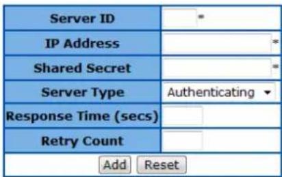
| Select | Server ID | IP Address | Shared secret | Server Type | Response Time (secs) | Retry Count |
| ApplyDelete | ||||||
Figure 58 - Layer2 Management >802.1X> Radius Settings
| Parameter | Description |
| Server ID | Specify the new RADIUS server ID. The possible ID is 1-10. |
| IP Address | Specify the IP address of the new RADIUS server. |
| Shared Secret | Specify the encryption key between RADIUS server and clients. |
| Server Type | Specify the server type of the RADIUS server. The options are:Authenticating – This server is only for RADIUS authentication.Accounting - This server is only for RADIUS accounting.Both - This RADIUS server support both authentication and accounting. |
| Response Time (secs) | Specify the time period that a client waits for the response from the RADIUS server before re-sending the request. The possible number is 1-120 seconds. |
| Retry Count | The maximum number that a client re-sends the request when there is no response from RADIUS server. The possible number is 1-254 times. |
Click Add to add a new RADIUS server, Reset to clear the value.
| Parameter | Description |
| Select | |
| Server ID | The RADIUS server ID. |
| IP Address | Specify the IP address of the RADIUS server. |
| Shared Secret | Specify the encryption key between RADIUS server and clients. |
| Server Type | Specify the server type of the RADIUS server. The options are:Authenticating – This server is only for RADIUS authentication.Accounting - This server is only for RADIUS accounting.Both - This RADIUS server support both authentication and accounting. |
| Response Time (secs) | Specify the time period that a client waits for the response from the RADIUS server before re-sending the request. The possible number is 1-120 seconds. |
| Retry Count | The maximum number that a client re-sends the request when there is no response from RADIUS server. The possible number is 1-254 times. |
Click Apply to submit the changes the setting of an existing RADIUS server, Delete to delete one.
IGMP Snooping
IGMP Snooping Configuration
This page is to configure the IGMP Snooping global settings.
IGMP Snooping Configuration

| Select | IGMP Snooping Status | Operational Status | Snooping Mode | Report Forwarding | Retry Count (1~5) | Query Transmit On TC |
| 0 | Disabled | Disabled | Mac Based | Router Ports | 2 | Disabled |
Apply
Figure 59 - Layer2 Management > IGMP Snooping > Basic Settings
Parameter
System Control
Description
To activate or shutdown IGMP snooping of the Switch. Select Start to activate the function, Shutdown to shutdown it. Default is Start.
Click Start to start or shutdown the IGMP Snooping globally.
Parameter
Select
IGMP Snooping Status
Operational Status
Snooping Mode
Report Forwarding
Retry Count (1\~5)
Query Transmit On TC
Description
Select a line to change the configuration.
To enable or disable IGMP Snooping globally. Default is enabled.
Specify the operational status of IGMP snooping function.
Specify the Snooping mode of IGMP snooping function.
Specify which port to forward the IGMP report. Select All Ports to forward the report to all ports, Router Ports to forward the reports to IGMP router ports only. Default is Router Ports.
To set the maximum retries for group specific queries which sent to a port received an IGMPv2 leave message. The possible number is 1-5 times. Default is 2.
Specify if the IGMP queries will still be sent when STP topology change happens. Select Enable to transmit the queries, Disabled not to transmit. Default is Disabled.
Click Apply to submit the changes.
IGMP Snooping Timer Configuration
This page is to configure the IGMP Snooping timers.
IGMP Snooping Timer Configuration
| Router Port Purge Interval (60~600 Secs) | 125 |
| Group-Member Port Purge Interval (130~1225 Secs) | 260 |
| Report Forward Interval (1~25 Secs) | 5 |
| Group Query Interval (1~5 Secs) | 1 |
| Querier Query Interval (60~600 Secs) | 125 |
| Apply Reset | |
Figure 60 - Layer2 Management > IGMP Snooping > Timer Configuration
| Parameter | Description |
| Router Port Purge Interval (60~600 Secs) | To set the time-out period that an IGMP multicast router port hasn't received IGMP router control packet, it will be deleted. Default is 125 seconds. |
| Group-Member Port Purge Interval (130~2335 Secs) | To set the purge interval that an IGMP member port hasn't' received IGMP report packet, it will be deleted. Default is 260 seconds. |
| Report Forward Interval (1~25 Secs) | To set the time interval that IGMPv2 report of the same group will not be forwarded to the router ports. Default is 5 seconds. |
| Group Query Interval (1~5 Secs) | To set up the time interval to send the group specific query. Default is 125 seconds. |
| Querier Query Interval (60~600 Secs) | To set up the time interval to send the IGMP general query. Default is 125 seconds. |
Click Apply to submit the changes, Reset to clear the values.
IGMP Snooping Interface Configuration
This page is used to configure the VLAN basis IGMP snooping settings.
IGMP Snooping Interface Configuration
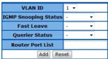
Select VLAN ID IGMP Snooping Status Current Version Fast Leave Configured Querier Status Current Querier Status Router Port List
Figure 61 - Layer2 Management > IGMP Snooping > Interface Configuration
| Parameter | Description |
| VLAN ID | Specify which VLAN to add to the IGMP snooping interface list below. |
| IGMP Snooping Status | Enable or disable the IGMP Snooping on this VLAN. |
| Fast Leave | Enable or disable the fast leave function on this VLAN. |
| Querier Status | Enable or disable the IGMP querier function on this VLAN. |
| Router Port List | Specify the IGMP router ports of this VLAN. |
Click Add to add a new VLAN to the list, Reset to clear the value.
| Parameter | Description |
| Select | Select which VLAN to apply the configuration changes. |
| VLAN ID | VLAN ID of this VLAN. |
| IGMP Snooping Status | Enable or disable the IGMP Snooping on this VLAN. |
| Current Version | Specify the IGMP version of this VLAN. |
| Fast Leave | Enable or disable the fast leave function on this VLAN. |
| Querier Status | Enable or disable the IGMP querier function on this VLAN. |
| Router Port List | Specify the IGMP router ports of this VLAN. |
Click Apply to submit the changes the IGMP snooping setting of an existing VLAN, Delete to delete one VLAN from the list.
24-Port 10/100Mbps Layer 2 Switch w/ 4 Gigabit Ports and 2 Shared Mini-GBIC Slots
IGMP Snooping VLAN Router Ports
This page is to display the static and dynamic learned IGMP router ports of each VLAN.
IGMP Snooping VLAN Router Ports
| VLAN ID | Static Port List | Dynamic Port List |
Figure 62 - Layer2 Management > IGMP Snooping > Router Ports
MAC Based Multicast Forwarding Table
This page is to display the IGMP group MAC address was learned.
MAC Based Multicast Forwarding Table
| Index | VLAN ID | Group MAC Address | Port List |
Figure 63 - Layer2 Management > IGMP Snooping > Group Information
Static MAC Entries
Static MAC Address Configuration
This page is to create or configure static unicast MAC address in the L2 forwarding database.
Static MAC

| Select | VLAN ID | MAC Address | Allowed Ports | Status |
Figure 64 – Layer2 Management > Static MAC Entries > Unicast Entries
| Parameter | Description |
| VLAN ID | Specify the VLAN ID of the new MAC address entry. |
| MAC Address | Specify the MAC address if this new entry. |
| Allowed Port | Specify the port allowed to forward the MAC address. |
| Status | Specify the attribute of this static MAC. The options are:Permanent- The static multicast will keep alive.DeleteOnReset- The static multicast will be deleted after switch reset.DeleteOnTimeout- The static multicast will be deleted when aging time out.Default is Permanent. |
Click Add to create a new static MAC, Reset to clear the value.
| Parameter | Description |
| Select | Select which MAC address to apply the configuration changes. |
| VLAN ID | VLAN ID of this MAC address belongs to. |
| MAC Address | The MAC address. |
| Allowed Port | Specify the port allowed to forward the MAC address. |
| Status | Specify the attribute of this static MAC. The options are:Permanent- The static multicast will keep alive.DeleteOnReset- The static multicast will be deleted after switch reset.DeleteOnTimeout- The static multicast will be deleted when aging time out.Default is Permanent. |
Click Apply to submit the changes the static MAC, Delete to delete it from the FDB.
Static Multicast Address Configuration
This page is to create/configure a static multicast MAC address in the L2 forwarding database.

Figure 65 - Layer2 Management > Static MAC Entries > Multicast Entries
| Parameter | Description |
| VLAN ID | Specify the VLAN ID of the new MAC address entry. |
| MAC Address | Specify the MAC address if this new entry. |
| Allowed Ports | Specify the port allowed to forward the MAC address. |
| Status | Specify the attribute of this static MAC. The options are:Permanent- The static multicast will keep alive.DeleteOnReset- The static multicast will be deleted after switch reset.DeleteOnTimeout- The static multicast will be deleted when aging time out.Default is Permanent. |
Click Add to create a new static MAC, Reset to clear the value.
| Parameter | Description |
| Select | Select which MAC address to apply the configuration changes. |
| VLAN ID | VLAN ID of this MAC address belongs to. |
| MAC Address | The MAC address. |
| Allowed Ports | Specify the port allowed to forward the MAC address. |
| Status | Specify the attribute of this static MAC. The options are:Permanent- The static multicast will keep alive.DeleteOnReset- The static multicast will be deleted after switch reset.DeleteOnTimeout- The static multicast will be deleted when aging time out.Default is Permanent. |
Click Apply to submit the changes the static MAC, Delete to delete it from the FDB.
Port Security Settings
This page is to configure the port security function for each port.
Port Security Settings
1-12 | 13-24 | 25-28 |
| Select | Port | Admin State | Max Learning Address(0-64) |
| 1 | Disable ▼ | 0 | |
| 2 | Disable ▼ | 0 | |
| 3 | Disable ▼ | 0 | |
| 4 | Disable ▼ | 0 | |
| 5 | Disable ▼ | 0 | |
| 6 | Disable ▼ | 0 | |
| 7 | Disable ▼ | 0 | |
| 8 | Disable ▼ | 0 | |
| 9 | Disable ▼ | 0 | |
| 10 | Disable ▼ | 0 | |
| 11 | Disable ▼ | 0 | |
| 12 | Disable ▼ | 0 |
Apply
Figure 66 – Layer2 Management > Static MAC Entries > Port Security Settings
| Parameter | Description |
| Select | Select a port to apply the configuration changes. |
| Port | Port ID. |
| Admin State | To enable or disable the port security function. Default is disable. |
| Max Learning Address (0-64) | Specify the maximum MAC address number of this port. |
Click Apply to submit the changes.
Click 1-12, 13-24, 25-28 to configure port security function for corresponding ports.
Chapter 7
Configuring ACL Functions
ACL Function List
- MAC ACL Configuration
- IP Standard ACL Configuration
- IP Extended ACL Configuration
- Classmap Settings
- Policymap Settings
MAC ACL Configuration
This page is to create/configure a rule to MAC Access Control List.
MAC ACL Configuration
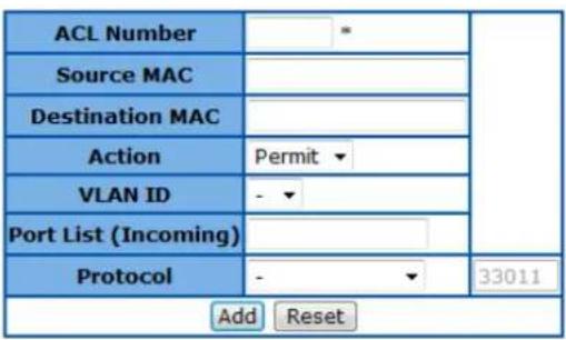
| Select | Number | Source MAC | Destination MAC | Action | VLANID | Port List (Incoming) | Protocol | Protocol Number |
Figure 67 - ACL > MAC ACL
| Parameter | Description |
| ACL Number | Specify the ACL ID of this rule. The possible ID of MAC ACL is 1-65535. |
| Source MAC | Matching packets with a specific source MAC address. |
| Destination MAC | Matching packets with a specific destination MAC address. |
| Action | Specify the action for packet matched. Select Permit to process the packets, Deny to discard them. |
| VLAN ID | Matching packets with a specific VLAN ID. |
| Port List (Incoming) | Specify the ports to apply this ACL rule. |
| Protocol | Matching packet with specific protocol (Ether type). The options are:Protocol Ether Typeaarp 0x80F3(33011).amber 0x6008(24584).dec-spanning 0x8138(33080).decnet-iv 0x6003(24579).diagnostic 0x6005(24581).dsm 0x8309(32825).etype-6000 0x6000(24576).etype-8042 0x8042(32834).lat 0x6004(24580). |
lavc-sca 0x6007(24583).
mop-console 0x6002(24578).
mop-dump 0x6001(24577).
msdos 0x8041(32833).
mumps 0x6009(24585).
netbios 0x8040(32832).
vines-echo 0x0BAF(2991).
vines-ip 0x0BAD(2989).
xns-id 0x0807(2055).
others Insert a custom Ether type (0-65535) to the right column.
Click Add to create a new ACL rule, Reset to clear the value.
Parameter
Select
ACL Number
Source MAC
Destination MAC
Action
VLAN ID
Port List (Incoming)
Protocol
Description
Select an ACL rule to apply the configuration changes.
Specify the ACL ID of this rule.
Matching packets with a specific source MAC address.
Matching packets with a specific destination MAC address.
Specify the action for packet matched. Select Permit to process the packets, Deny to discard them.
Matching packets with a specific VLAN ID.
Specify the ports to apply this ACL rule.
Matching packet with specific protocol (Ether type). The options are:
Protocol Ether Type
aarp 0x80F3(33011).
amber 0x6008(24584).
dec-spanning 0x8138(33080).
decnet-iv 0x6003(24579).
diagnostic 0x6005(24581).
dsm 0x8309(32825).
etype-6000 0x6000(24576).
etype-8042 0x8042(32834).
lat 0x6004(24580).
lavc-sca 0x6007(24583).
mop-console 0x6002(24578).
mop-dump 0x6001(24577).
msdos 0x8041(32833).
mumps 0x6009(24585).
netbios 0x8040(32832).
vines-echo 0x0BAF(2991).
vines-ip 0x0BAD(2989).
xns-id 0x0807(2055).
others
Protocol Number
Specify the Ether type for the protocol.
Click Apply to submit the changes to the ACL rule, Delete to delete it.
IP Standard ACL Configuration
This page is to create/configure a rule to IP standard Access Control List.
IP Standard ACL Configuration


Figure 68 - ACL > IP Standard ACL
| Parameter | Description |
| ACL Number | Specify the ACL ID of this rule. The possible ID of IP Standard ACL is 1-1000. |
| Action | Specify the action for packet matched. Select Permit to process the packets, Deny to discard them. |
| Source IP Address | Matching packet with a specific source IP address. |
| Subnet Mask | Matching packet with a range of source IP address. For example 172.17.5.1 with mask 255.255.255.0 means 172.15.5.0~255. |
| Destination IP Address | Matching packet with a specific destination IP address. |
| Subnet Mask | Matching packet with a range of destination IP address. For example 172.17.5.1 with mask 255.255.255.0 means 172.15.5.0~255. |
| Port List (Incoming) | Specify the ports to apply this ACL rule. |
Click Add to create a new ACL rule, Reset to clear the value.
| Parameter | Description |
| Select | Select an ACL rule to apply the configuration changes. |
| ACL Number | Specify the ACL ID of this rule. |
| Action | Specify the action for packet matched. Select Permit to process the packets, Deny to discard them. |
| Source IP Address | Matching packet with a specific source IP address. |
| Subnet Mask | Matching packet with a range of source IP address. For example 172.17.5.1 with mask 255.255.255.0 means 172.15.5.0~255. |
| Destination IP Address | Matching packet with a specific destination IP address. |
| Subnet Mask | Matching packet with a range of destination IP address. For example 172.17.5.1 with mask 255.255.255.0 means 172.15.5.0~255. |
| Port List (Incoming) | Specify the ports to apply this ACL rule. |
Click Apply to submit the changes to the ACL rule, Delete to delete it.
IP Extended ACL Configuration
This page is to create/configure a rule to IP Extended Access Control List.
IP Extended ACL Configuration

| Select | Filter No | Action | Source IP | Subnet Mask | Destination IP | Subnet Mask | Port List (Incoming) | Protocol | Other | Code | Type | Dscp | TOS | ACK Bit | RSI Bit | Source Port | Source Port Mask | Destination Port | Destination Port Mask |
Figure 69 - ACL > IP Extended ACL
| Parameter | Description |
| ACL Number | Specify the ACL ID of this rule. The possible ID of IP Standard ACL is 1001-65535. |
| Action | Specify the action for packet matched. Select Permit to process the packets, Deny to discard them. |
| Source IP Address | Matching packet with a specific source IP address. |
| Subnet Mask | Matching packet with a range of source IP address. For example 172.17.5.1 with mask 255.255.255.0 means 172.15.5.0~255. |
| Destination IP Address | Matching packet with a specific destination IP address. |
| Subnet Mask | Matching packet with a range of destination IP address. For example 172.17.5.1 with mask 255.255.255.0 means 172.15.5.0~255. |
| Port List (Incoming) | Specify the ports to apply this ACL rule. |
| Protocol | Matching the L4 protocol type of the packet. The options are: icmp, ip, tcp, udp, ospf, pim and other.When selecting others, insert the protocol ID in the right column. |
| Message Code | Matching ICMP packets with specific message type. The possible code is 0-255. |
| Message Type | Matching ICMP packets with specific message code. The possible type is 0-255. |
| Dscp | Matching packets with specific DSCP type. The possible value is 0-63. |
| TOS | Matching packets with specific ToS value. The possible value is 0-7 |
| ACK Bit | Matching packets with a specific TCP acknowledge flag. The options are: Establish - TCP ACK packet.Not Establish - TCP ACK-not packet.Any - Any kind of TCP acknowledge packet. |
| RST Bit | Matching packets with a specific TCP reset flag. The options are:Set - TSP reset packet.Not Set - TCP reset-not packet.Any - Any kind of TCP reset packet. |
| Source Port | Matching packets with a specific L4 source port. |
| Source Port Mask | Matching packet with a range of source port. For example source port 23 with mask FFFE means 22~23. The mask options are: 8000, C000, E000, F000, F800, FC00, FE00, FF00, FF80, FFC0, FFE0, FFF0, FFF8, FFFC, FFFE, FFFF. |
| Destination Port | Matching packets with a specific L4 destination port. |
| Destination Port Mask | Matching packet with a range of destination port. For example source port 23 with mask FFFE means 22~23. The mask options are: 8000, C000, E000, F000, F800, FC00, FE00, FF00, FF80, FFC0, FFE0, FFF0, FFF8, FFFC, FFFE, FFFF. |
Click Add to create a new ACL rule, Reset to clear the value.
| Parameter | Description |
| Select | Select an ACL rule to apply the configuration changes. |
| ACL Number | Specify the ACL ID of this rule. |
| Action | Specify the action for packet matched. Select Permit to process the packets, Deny to discard them. |
| Source IP Address | Matching packet with a specific source IP address. |
| Subnet Mask | Matching packet with a range of source IP address. For example 172.17.5.1 with mask 255.255.255.0 means 172.15.5.0~255. |
| Destination IP Address | Matching packet with a specific destination IP address. |
| Subnet Mask | Matching packet with a range of destination IP address. For example 172.17.5.1 with mask 255.255.255.0 means 172.15.5.0~255. |
| Port List (Incoming) | Specify the ports to apply this ACL rule. |
| Protocol | Matching the L4 protocol type of the packet. The options are: icmp, ip, tcp, udp, ospf, pim and other.When selecting others, insert the protocol ID in the right column. |
| Message Code | Matching ICMP packets with specific message type. The possible code is 0-255. |
| Message Type | Matching ICMP packets with specific message code. The possible type is 0-255. |
| Dscp | Matching packets with specific DSCP type. The possible value is 0-63. |
| TOS | Matching packets with specific ToS value. The possible value is 0-7 |
| ACK Bit | Matching packets with a specific TCP acknowledge flag. The options are: Establish - TCK ACK packet.Not Establish - TCP ACK-not packet.Any - Any kind of TCP acknowledge packet. |
| RST Bit | Matching packets with a specific TCP reset flag. The options are:Set - TSP reset packet.Not Set - TCP reset-not packet.Any - Any kind of TCP reset packet. |
| Source Port | Matching packets with a specific L4 source port. |
| Source Port Mask | Matching packet with a range of source port. For example source port 23 with mask FFFE means 22~23. The mask options are: 8000, C000, E000, F000, F800, FC00, FE00, FF00, FF80, FFC0, FFE0, FFF0, FFF8, FFFC, FFFE, FFFF. |
| Destination Port | Matching packets with a specific L4 destination port. |
| Destination Port Mask | Matching packet with a range of destination port. For example source port 23 with mask FFFE means 22~23. The mask options are: 8000, C000, E000, F000, F800, FC00, FE00, FF00, FF80, FFC0, FFE0, FFF0, FFF8, FFFC, FFFE, FFFF. |
Click Apply to submit the changes to the ACL rule, Delete to delete it.
Classmap Settings
This page is to create/configure a Classmap.
QOS Classmap Settings


Figure 70 - ACL > Classmap
| Parameter | Description |
| Classmap ID | Specify the classmap ID. The possible value is 1-65535. |
| ACL ID | Specify the ACL rule ID to bind. |
| ACL Type | Specify the type of the ACL rule. |
Click Add to create a new classmap, Reset to clear the value.
| Parameter | Description |
| Select | Select a classmap to delete |
| Classmap ID | The classmap ID. |
| ACL ID | The ID of binding ACL rule. |
| ACL Type | The type of binding ACL rule. |
Click Delete to delete selected classmap.
Policymap Settings
This page is to create/configure a policymap.
QoS Policymap Settings
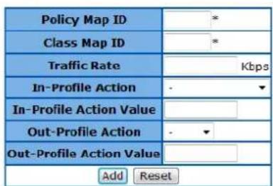
Select Policy Map ID Class Map ID Traffic Rate In-Profile Action type In-Profile Action value Out-Profile Action type Out-Profile Action value
Figure 71 - ACL >Pokicymap
| Parameter | Description |
| Policy Map ID | Specify the policymap ID. The possible value is 1-65535. |
| Classmap ID | Specify which classmap to bind. |
| Traffic Rate | Set the traffic rate threshold in Kbps for the class map. |
| In-Profile Action | Specify the action to packets do not exceed the rate threshold. The options are: |
| Policed-DSCP - Assign a new DSCP value to the packets.Policed-Priority - Assign a new 802.1p priority to the packets. | |
| In-Profile Action Value | Specify the new value of above. When rewriting DSCP tag, the possible value is 0-63; when rewriting the 802.1p priority, the possible value is 0-7. |
| Out-Profile Action | Specify the action to packets exceed the rate threshold. The options are:Drop - Drop the packets.Policy DSCP - Assign a new DSCP value to the packets. |
| Out-Profile Action Value | Specify the new value of DSCP tag. The possible value is 0-63. |
Click Add to create a new policymap, Reset to clear the value.
| Parameter | Description |
| Policy Map ID | Specify the policymap ID. The possible value is 1-65535. |
| Classmap ID | Specify which classmap to bind. |
| Traffic Rate | Set the traffic rate threshold in Kbps for the class map. |
| In-Profile Action | Specify the action to packets do not exceed the rate threshold. The options are:Policed-DSCP - Assign a new DSCP value to the packets.Policed-Priority - Assign a new 802.1p priority to the packets. |
| In-Profile Action Value | Specify the new value of above. When rewriting DSCP tag, the possible value is 0-63; when rewriting the 802.1p priority, the possible value is 0-7. |
| Out-Profile Action | Specify the action to packets exceed the rate threshold. The options are:Drop - Drop the packets.Policy DSCP - Assign a new DSCP value to the packets. |
| Out-Profile Action Value | Specify the new value of DSCP tag. The possible value is 0-63. |
Click Apply to submit the changes to the policymap, Delete to delete it.
Chapter 8
Configuring QoS Functions
QoS Function List
- Rate Limiting
■ Storm Control Settings - 802.1p Queue Mapping
■ 802.1p Port Priority - DSCP Queue Mapping
- Egress Queue Scheduling Settings
Rate Limiting
This page is to configure the rate limiting function on each port.
Rate Limiting
1-12 | 13-24 | 25-28 |
| Select | Port | Ingress RateLimit(0,64~1000000 Kbps) | Egress RateLimit(0,64~1000000 Kbps) |
| ◎ | 1 | 0 | 0 |
| ◎ | 2 | 0 | 0 |
| ◎ | 3 | 0 | 0 |
| ◎ | 4 | 0 | 0 |
| ◎ | 5 | 0 | 0 |
| ◎ | 6 | 0 | 0 |
| ◎ | 7 | 0 | 0 |
| ◎ | 8 | 0 | 0 |
| ◎ | 9 | 0 | 0 |
| ◎ | 10 | 0 | 0 |
| ◎ | 11 | 0 | 0 |
| ◎ | 12 | 0 | 0 |
Note 1: It means Ingress / Egress rate limit disable if Ingress / Egress RateLimit is 0.
Note 2: The multiple of 1850 Kbits/sec will be set automatically because the resolution of Giga-port Egress RateLimit is 1850 Kbits/sec.
Note 3: In fastethernet ports, the Ingress / Egress RateLimit support to 100000 Kbps.
Apply
Figure 72 - QoS > Rate Limiting
| Parameter | Description |
| Select | Select a port to configure rate limiting function. |
| Port | Port ID. |
| Ingress RateLimit (0,64~1000000 Kbps) | Specify the traffic Kbit per second is allowed to be transmitted for an ingress port. 0 means no limit. |
| Egress RateLimit (0,64~1000000 Kbps) | Specify the traffic Kbit per second is allowed to be transmitted for an egress port. 0 means no limit. |
Click Apply to submit the changes.
Click 1-12, 13-24, 25-28 to configure rate limiting for corresponding ports.
Storm Control Settings
This page is to configure the storm control function of the device.
Storm Control Settings

Figure 73 - QoS > Storm Global Settings
| Parameter | Description |
| System Control | To activate or shutdown storm control function of the Switch. Select Enable to activate link aggregation function, Disabled to shutdown it. Default is Start. |
| Packet Type | Specify which kind of packets to be controlled. The options are:Broadcast only - Control broadcast packets only.Multicast and Broadcast - Control both multicast and broadcast packets.DLF and Multicast and Broadcast - Control Destination Lookup Failed unicast, multicast and broadcast packets. |
| Rate Limit | Specify the maximum packet rate is allowed per second. |
802.1p Queue Mapping
This page is to configure the 802.1p priority and queue mapping.
VLAN Traffic Class Mapping
| Priority 0 | Class-0 |
| Priority 1 | Class-0 |
| Priority 2 | Class-1 |
| Priority 3 | Class-1 |
| Priority 4 | Class-2 |
| Priority 5 | Class-2 |
| Priority 6 | Class-3 |
| Priority 7 | Class-3 |
Apply
Figure 74 - QoS > 802.1p
Parameter
Priority 0\~7
Description
Specify which switch queue to map. The options are Class-0, Class-1, Class-2 and Class-3.
Click Apply to submit the changes.
802.1p Port Priority
This page is to configure the 802.1p priority for untagged packets receive from each port.
Port Priority
1-12 | 13-24 | 25-28 |
| Select | Port | User Priority |
|  | 1 | 0✓ |
|  | 2 | 0✓ |
|  | 3 | 0✓ |
|  | 4 | 0✓ |
|  | 5 | 0✓ |
|  | 6 | 0✓ |
|  | 7 | 0✓ |
|  | 8 | 0✓ |
|  | 9 | 0✓ |
|  | 10 | 0✓ |
|  | 11 | 0✓ |
|  | 12 | 0✓ |
Apply
Figure 75 - QoS > Port Priority
| Parameter | Description |
| Select | Select a port to submit the configuration changes. |
| Port | Port ID. |
| User Priority | Specify 802.1p priority of untagged packets. |
Click Apply to submit the changes.
Click 1-12, 13-24, 25-28 to configure port priority for corresponding ports.
DSCP Queue Mapping
This page is to enable/configure the DSCP and queue mapping.
DSCP Class Mapping

Apply
Type0-15 | Type16-31 | Type32-47 | Type48-63
| Type00 | Class-0 | Type01 | Class-0 | Type02 | Class-0 | Type03 | Class-0 |
| Type04 | Class-0 | Type05 | Class-0 | Type06 | Class-0 | Type07 | Class-0 |
| Type08 | Class-0 | Type09 | Class-0 | Type10 | Class-0 | Type11 | Class-0 |
| Type12 | Class-0 | Type13 | Class-0 | Type14 | Class-0 | Type15 | Class-0 |
Apply
Figure 76 - QoS > DSCP
| Parameter | Description |
| DSCP Mapping | To enable the DSCP queue mapping. When disabled, Switch will map queue with 802.1p priority. |
Click Apply to submit the changes.
| Parameter | Description |
| Type00~63 | Specify which switch queue to map. The options are Class-0, Class-1, Class-2 and Class-3. |
Click Type0-15, 16-31, 32-47, 48-63 to configure queue mapping for corresponding DSCP levels. Click Apply to submit the changes.
Egress Queue Scheduling Settings
This page is to configure the scheduling algorithm for switch queues.
COSQ Scheduling Algorithm Settings


Figure 77 - QoS > Egress Algorithm
| Parameter | Description |
| Scheduling Algorithm | Select the algorithm of queue scheduling. The options are:Strict Priority - The traffic in highest queue always process first.Weighted RoundRobin - Using weighted round-robin algorithm to handle packets in priority queues.Default is Strict Priority. |
Click Apply to submit the changes.
Chapter 9
Configuring RMON Functions
RMON Function List
- RMON Basic Settings
■ RMON Statistics Configuration - RMON History Configuration
■ RMON Alarms Configuration - RMON Events Configuration
RMON Basic Settings
This page is to enable or disable RMON function
RMON Basic Settings
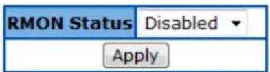
Figure 78 - RMON > Global Settings
Parameter
RMON Status
Description
To enable or disable RMON function. Default is Disabled.
Click Apply to submit the changes.
RMON Statistics Configuration
Ethernet Statistics Configuration

First | Prev | Next | Last |
| Select | Index | Port | Drop Events | Octets | Packets | Broadcast Packets | Multiast Packets | Owner | Status |
Figure 79 - RMON > Statistics
Parameter
Index (1\~65535)
Port
Owner
Description
Specify the index of the RMON statistics collection.
Specify which port to enable the RMON statistics collection.
Specify the owner of the statistics entry.
Click Add to create a new statistics entry, Reset to clear the value.
| Parameter | Description |
| Select | Select a RMON statistics entry to apply the |
| Index | The index of the RMON statistics collection. |
| Port | The port of the RMON statistics collection. |
| Drop Events | The number of events was dropped due to lack of resources. |
| Octets | The total number of octets received from this port. |
| Packets | The total number of packets received from this port. |
| Broadcast Packets | The total number of broadcast packets received from this port. |
| Multicast Packets | The total number of multicast packets received from this port. |
| Owner | Specify the owner of the statistics. |
| Status | Specify the status of this statistics entry. The options are:Valid - The statistics entry is valid.Under Creation -Invalid - The statistics entry is invalid and will be deleted. |
Click Apply to submit the changes.
RMON History Configuration
This page is to configure the RMON history settings on ports.
History Control Configuration


Figure 80 - RMON > History
| Parameter | Description |
| Index (1~65535) | Specify the index of the RMON history collection. |
| Port | Specify which port to enable the RMON history collection. |
| Buckets Requested (1~50) | Specify the maximum number of RMON history collection. |
| Interval (1~3600 secs) | Specify the time interval for the history collection. |
| Owner | Specify the owner of the history entry. |
Click Add to create a new history entry, Reset to clear the value.
| Parameter | Description |
| Select | Select a RMON history entry to apply the |
| Index | The index of the RMON history collection. |
| Port | The port of the RMON history collection. |
| Buckets Requested | Specify the maximum number of RMON history collection. |
| Buckets Granted | The number of bucket granted for collecting the RMON history. |
| Interval | Specify the time interval for the history collection. |
| Owner | Specify the owner of the history entry. |
| Status | Specify the status of this history entry. The options are:Valid - The history entry is valid.Under Creation -Invalid - The history entry is invalid and will be deleted. |
Click Apply to submit the changes.
RMON Alarms Configuration
To set a RMON alarm to a MIB object.
RMON Alarm Configuration
| Index (1~65535) | * |
| Interval (1~2^31-1 secs) | |
| Variable | * |
| Sample type | Absolute value ▼ |
| Rising Threshold (0~2^31-1) | |
| Falling Threshold (0~2^31-1) | |
| Rising Event Index (1~65535) | |
| Falling Event Index (1~65535) | |
| Owner | |
| Apply Reset | |
| Select | Index | Interval | Variable | Sample Type | Rising Threshold | Falling Threshold | Rising Event Index | Falling Event Index | Owner | Status |
| Apply |
Figure 81 - RMON > Alarms
| Parameter | Description |
| Index (1~65535) | Specify the index of the RMON alarm. |
| Interval (1~2^31-1 secs) | The time interval in seconds that alarm monitors the MIB variable. |
| Variable | The MIB OID to set alarm. |
| Sample type | The type of the alarm sampling. The options are:Absolute value - To test the MIB variable directly.Delta value - To test the change between samples of a MIB variable. |
| Rising Threshold (0~2^31-1) | The threshold value to trigger alarm when the number of sample exceeds. |
| Falling Threshold (0~2^31-1) | The threshold value to reset alarm when the number of sample exceeds. |
| Rising Event Index (1~65535) | The number of event to trigger when rising threshold is exceeded. |
| Falling Event Index (1~65535) | The number of event to trigger when falling threshold is exceeded. |
| Owner | Specify the owner of the alarm entry. |
Click Add to create a new RMON alarm, Reset to clear the value.
| Parameter | Description |
| Select | Select a RMON alarm entry to apply the configuration changes. |
| Index | Specify the index of the RMON alarm. |
| Interval | The time interval in seconds that alarm monitors the MIB variable. |
| Variable | The MIB OID of this alarm entry. |
| Sample type | The type of the alarm sampling. The options are:Absolute value - To test the MIB variable directly.Delta value - To test the change between samples of a MIB variable. |
| Rising Threshold | The threshold value to trigger alarm when the number of sample exceeds. |
| Falling Threshold | The threshold value to reset alarm when the number of sample exceeds. |
| Rising Event Index | The number of event to trigger when rising threshold is exceeded. |
| Falling Event Index | The number of event to trigger when falling threshold is exceeded. |
| Owner | Specify the owner of the alarm entry. |
| Status | Specify the status of this alarm entry. The options are:Valid - The alarm entry is valid.Under Creation -Invalid - The alarm entry is invalid and will be deleted. |
Click Apply to submit the changes.
RMON Events Configuration
This page is to add an event to RMON event table.
Event Configuration

First | Prev | Next | Last |

Figure 82 - RMON > Events
| Parameter | Description |
| Index (1~65535) | Specify the index of the RMON event. |
| Description | Specify the description of the event. |
| Type | Specify the action type of the event. The options are:Log - Generating syslog when event is triggered.SNMP Trap - Generating a trap message when event is triggered.Log and Trap - Generating both log and trap message when event is triggered. |
| Community | Specify the SNMP community string used for the traps. |
| Owner | Specify the owner of the event entry. |
Click Add to create a new RMON event, Reset to clear the value.
| Parameter | Description |
| Index | Specify the index of the RMON event. |
| Description | Specify the description of the event. |
| Type | Specify the action type of the event. The options are:Log - Generating syslog when event is triggered.SNMP Trap - Generating a trap message when event is triggered.Log and Trap - Generating both log and trap message when event is triggered. |
| Community | Specify the SNMP community string used for the traps. |
| Owner | Specify the owner of the alarm entry. |
| Status | Specify the status of this event entry. The options are:Valid - The event entry is valid.Under Creation -Invalid - The events entry is invalid and will be deleted. |
Click Apply to submit the changes.
Chapter 10
Switch Statistics
Switch Statistics List
- Interface Statistics
- Ethernet Statistics
■ VLAN Statistics
■ MSTP
MSTP Information MSTP CIST Port Statistics MSTP MSTI Port Statistics
■ RSTP
RSTP Information RSTP Port Statistics
• LA
LA Port Statistics LA Neighbour Statistics Information
802.1X
802.1X Session Statistics RADIUS Server Statistics - IGMP Snooping
IGMP Snooping Clear Statistics IGMP Snooping V1/V2 Statistics
IP
ARP Cache ICMP Statistics
■ RMON - MAC Address Table
SNMP
Interface Statistics
This page is to display the traffic statistics of each port.
Interface Statistics
1-12 | 13-24 | 25-28 |
| Index | MTU | Speed (Bits Per Second) | Received Octets | Received Unicast Packets | Received Nunicast Packets | Received Discards | Received Errors | Received Unknown Protocols | Transmitted Octets | Transmitted Unicast Packets | Transmitted Nunicast Packets | Transmitted Discards | Transmitted Errors |
| 1 | 1522 | 100000000 | 0 | 0 | 0 | 0 | 0 | 0 | 0 | 0 | 0 | 0 | 0 |
| 2 | 1522 | 100000000 | 0 | 0 | 0 | 0 | 0 | 0 | 0 | 0 | 0 | 0 | 0 |
| 3 | 1522 | 100000000 | 0 | 0 | 0 | 0 | 0 | 0 | 0 | 0 | 0 | 0 | 0 |
| 4 | 1522 | 100000000 | 0 | 0 | 0 | 0 | 0 | 0 | 0 | 0 | 0 | 0 | 0 |
| 5 | 1522 | 100000000 | 35128600 | 75047 | 769 | 0 | 0 | 0 | 22039641 | 58369 | 49372 | 0 | 0 |
| 6 | 1522 | 100000000 | 0 | 0 | 0 | 0 | 0 | 0 | 0 | 0 | 0 | 0 | 0 |
| 7 | 1522 | 100000000 | 0 | 0 | 0 | 0 | 0 | 0 | 0 | 0 | 0 | 0 | 0 |
| 8 | 1522 | 100000000 | 0 | 0 | 0 | 0 | 0 | 0 | 0 | 0 | 0 | 0 | 0 |
| 9 | 1522 | 100000000 | 0 | 0 | 0 | 0 | 0 | 0 | 0 | 0 | 0 | 0 | 0 |
| 10 | 1522 | 100000000 | 0 | 0 | 0 | 0 | 0 | 0 | 0 | 0 | 0 | 0 | 0 |
| 11 | 1522 | 100000000 | 0 | 0 | 0 | 0 | 0 | 0 | 0 | 0 | 0 | 0 | 0 |
| 12 | 1522 | 100000000 | 0 | 0 | 0 | 0 | 0 | 0 | 0 | 0 | 0 | 0 | 0 |
Figure 83 – Statistics > Interface
Click 1-12, 13-24, 25-28 to display the Ethernet related statistics of corresponding ports.
Ethernet Statistics
This page is to display the Ethernet related statistics of each port.
Ethernet Statistics
1-12 | 13-24 | 25-28 |
| Index | Alignment Errors | FCS Errors | Single Collision Frames | Multiple Collision Frames | SQE Test Errors | Deferred Transmissions | Late Collisions | Excess Collisions | Transmitted Internal MAC Errors | Carrier Sense Errors | Frame Too Long | Received Internal MAC Errors | Ether ChipSet | Symbol Errors | Duplex Status |
| 1 | 0 | 0 | 0 | 0 | 1096427445 | 0 | 0 | 0 | 0 | 0 | 0 | 0 | 1 | 0 | Half-Duplex |
| 2 | 0 | 0 | 0 | 0 | 1096427445 | 0 | 0 | 0 | 0 | 0 | 0 | 0 | 1 | 0 | Half-Duplex |
| 3 | 0 | 0 | 0 | 0 | 1096427445 | 0 | 0 | 0 | 0 | 0 | 0 | 0 | 1 | 0 | Half-Duplex |
| 4 | 0 | 0 | 0 | 0 | 1096427445 | 0 | 0 | 0 | 0 | 0 | 0 | 0 | 1 | 0 | Half-Duplex |
| 5 | 0 | 0 | 0 | 0 | 1096427445 | 0 | 0 | 0 | 0 | 0 | 0 | 0 | 1 | 0 | Full-Duplex |
| 6 | 0 | 0 | 0 | 0 | 1096427445 | 0 | 0 | 0 | 0 | 0 | 0 | 0 | 1 | 0 | Half-Duplex |
| 7 | 0 | 0 | 0 | 0 | 1096427445 | 0 | 0 | 0 | 0 | 0 | 0 | 0 | 1 | 0 | Half-Duplex |
| 8 | 0 | 0 | 0 | 0 | 1096427445 | 0 | 0 | 0 | 0 | 0 | 0 | 0 | 1 | 0 | Half-Duplex |
| 9 | 0 | 0 | 0 | 0 | 1096427445 | 0 | 0 | 0 | 0 | 0 | 0 | 0 | 1 | 0 | Half-Duplex |
| 10 | 0 | 0 | 0 | 0 | 1096427445 | 0 | 0 | 0 | 0 | 0 | 0 | 0 | 1 | 0 | Half-Duplex |
| 11 | 0 | 0 | 0 | 0 | 1096427445 | 0 | 0 | 0 | 0 | 0 | 0 | 0 | 1 | 0 | Half-Duplex |
| 12 | 0 | 0 | 0 | 0 | 1096427445 | 0 | 0 | 0 | 0 | 0 | 0 | 0 | 1 | 0 | Half-Duplex |
Figure 84 – Statistics > Ethernet
Click 1-12, 13-24, 25-28 to display the Ethernet related statistics of corresponding ports.
VLAN Statistics
This page is to display current VLAN and its member port information of the Switch.
VLAN Current Database
| VLAN ID | VLAN FDB ID | Member Ports | Untagged Ports | Status |
| 1 | 1 | 1-28 | 1-28 | Permanent |
Figure 85 – Statistics > VLAN
MSTP
MSTP Information
This page is to display current MSTP settings and states of the Switch.
MSTP Information
| Context Id | Bridge Address | CIST Root | Regional Root | CIST Root Cost | Regional Root Cost | Root Port | Hold Time | Max Age | Forward Delay | Config Digest | CIST Time Since Topology Change | Topology Changes |
| 0 | 00:00:00:00:00:00 | 00:00:00:00:00:00:00:00 | 00:00:00:00:00:00:00:00 | 0 | 0 | 0 | 1 | 20 | 15 | 0 | 0 |
Figure 86 - Statistics > MSTP > MSTP Information
MSTP CIST Port Statistics
This page is to display the MSTP traffic statistics of ports.

MSTP CIST Port Statistics
1-12 | 13-24 | 25-28 |
| Port | Received MST BPDUs | Received RST BPDUs | Received Config BPDUs | Received TCN BPDUs | Transmitted MST BPDUs | Transmitted RST BPDUs | Transmitted Config BPDUs | Transmitted TCN BPDUs | Received Invalid MST BPDUs | Received Invalid RST BPDUs | Received Invalid Config BPDUs | Received Invalid TCN BPDUs | Protocol Migration Count |
Figure 87 – Statistics > MSTP > CIST Port Statistics
| Parameter | Description |
| Clear Counters | Update – To display the latest statistics information.Clear – To reset all MSTP traffic counters. |
Click Apply to update or clear the statistics of the Swtich.
Click 1-12, 13-24, 25-28 to display the MSTP traffic statistics of corresponding ports.
MSTP MSTI Port Statistics
This page is to display the MSTP traffic statistics of different instances in each port.
MSTP MSTI Port Statistics
| Instance | Port | Designated Root | Designated Bridge | Designated Port | State | Forward Transitions | Received BPDUs | Transmitted BPDUs | Invalid Received BPDUs | Designated Cost | Role |
Figure 88 – Statistics > MSTP > MSTI Port Statistics
RSTP
RSTP Information
This page is to display current RSTP setting and states of the Switch.
RSTP Information
| Context Id | Protocol Specification | Time Since Topology Change | Designated Root | Root Brg Priority | Root Cost | Root Port | Max Age | Hello Time | Hold Time | Forward Delay |
| 0 | 3 | 3 | 00.00.00.00.00.00.00.00 | 0 | 0 | 0 | 20 | 2 | 1 | 15 |
Figure 89 – Statistics > RSTP > RSTP Information
RSTP Port Statistics
This page is to display the RSTP traffic statistics of ports.
RSTP Port Statistics
1-12 | 13-24 | 25-28 |
| Clear Counters | |
| Apply | |
| Port | Received RST BPDUs | Received Configuration BPDUs | Received TCN | Transmitted RST BPDUs | Transmitted Configuration BPDUs | Transmitted TCN | Received Invalid RST BPDUs | Received Invalid Configuration BPDUs | Received Invalid TCN BPDUs | Protocol Migration Count | Effective Port State | EdgePort Oper Status | Link Type |
| 1 | 0 | 0 | 0 | 0 | 0 | 0 | 0 | 0 | 0 | 0 | Disable | - | - |
Figure 90 – Statistics > RSTP > Port Statistics
Parameter
Clear Counters
Description
Update – To display the latest statistics information.
Clear – To reset all RSTP traffic counters.
Click Apply to update or clear the statistics of the Switch.
Click 1-12, 13-24, 25-28 to display the Link Aggregation neighbours information of corresponding ports.
LA
LA Port Statistics
This page is to display the traffic statistics of Link Aggregation ports.
Port Channel Port Statistics
1-12 | 13-24 | 25-28 |
| Port | Received PDUs | Received Unknown PDUs | Received Illegal PDUs | Transmitted PDUs |
| 1 | 0 | 0 | 0 | 0 |
| 2 | 0 | 0 | 0 | 0 |
| 3 | 0 | 0 | 0 | 0 |
| 4 | 0 | 0 | 0 | 0 |
| 5 | 0 | 0 | 0 | 0 |
| 6 | 0 | 0 | 0 | 0 |
| 7 | 0 | 0 | 0 | 0 |
| 8 | 0 | 0 | 0 | 0 |
| 9 | 0 | 0 | 0 | 0 |
| 10 | 0 | 0 | 0 | 0 |
| 11 | 0 | 0 | 0 | 0 |
| 12 | 0 | 0 | 0 | 0 |
Figure 91 – Statistics > LA > Port LACP Stats
Click 1-12, 13-24, 25-28 to display the Link Aggregation neighbours information of corresponding ports.
LA Neighbour Statistics Information
This page is to display the information of Link Aggregation neibubours.
Port Channel Neighbour Statistics Information
1-12 | 13-24 | 25-28 |
| Port | Partner SystemID | Oper Key | Partner Port Priority |
| 1 | 00:00:00:00:00:00 | 0 | 0 |
| 2 | 00:00:00:00:00:00 | 0 | 0 |
| 3 | 00:00:00:00:00:00 | 0 | 0 |
| 4 | 00:00:00:00:00:00 | 0 | 0 |
| 5 | 00:00:00:00:00:00 | 0 | 0 |
| 6 | 00:00:00:00:00:00 | 0 | 0 |
| 7 | 00:00:00:00:00:00 | 0 | 0 |
| 8 | 00:00:00:00:00:00 | 0 | 0 |
| 9 | 00:00:00:00:00:00 | 0 | 0 |
| 10 | 00:00:00:00:00:00 | 0 | 0 |
| 11 | 00:00:00:00:00:00 | 0 | 0 |
| 12 | 00:00:00:00:00:00 | 0 | 0 |
Figure 92 – Statistics > LA > Neighbour Stats
Click 1-12, 13-24, 25-28 to display the Link Aggregation neighbours information of corresponding ports.
802.1X
802.1X Session Statistics
This page is to display the statistics and status of current authenticated users.
802.1x Session Statistics
1-12 | 13-24 | 25-28 |
| Port | Session ID | Received Frames | Transmitted Frames | Session Time (secs) | Session Terminate Cause | User Name |
| 1 | 1-0 | 0 | 0 | 1980400 | Admin Disabled | No User |
| 2 | 2-0 | 0 | 0 | 1980400 | Admin Disabled | No User |
| 3 | 3-0 | 0 | 0 | 1980400 | Admin Disabled | No User |
| 4 | 4-0 | 0 | 0 | 1980400 | Admin Disabled | No User |
| 5 | 5-0 | 76797 | 109486 | 1980400 | Admin Disabled | No User |
| 6 | 6-0 | 0 | 0 | 1980400 | Admin Disabled | No User |
| 7 | 7-0 | 0 | 0 | 1980400 | Admin Disabled | No User |
| 8 | 8-0 | 0 | 0 | 1980400 | Admin Disabled | No User |
| 9 | 9-0 | 0 | 0 | 1980400 | Admin Disabled | No User |
| 10 | 10-0 | 0 | 0 | 1980400 | Admin Disabled | No User |
| 11 | 11-0 | 0 | 0 | 1980400 | Admin Disabled | No User |
| 12 | 12-0 | 0 | 0 | 1980400 | Admin Disabled | No User |
Figure 93 – Statistics > 802.1X > Session Stats
Click 1-12, 13-24, 25-28 to display the statistics for corresponding ports.
RADIUS Server Statistics
This page is to display the traffic statistics to RADIUS server.
Radius Server Statistics
| Index | Radius Server Address | UDP Port Number | Round Trip Time | No of Request Packets | No of Retransmitted Packets | No of Access-Accept Packets | No of Access-Reject Packets | No of Access-Challenge Packets | No of Malformed Access Responses | No of Bad Authenticators | No of Pending Requests | No of Time Outs | No of Unknown Types |
Figure 94 - Statistics >802.1X> Radius
IGMP Snooping
IGMP Snooping Clear Statistics
This page is to reset the IGMP Snooping traffic counters.
IGMP Snooping Clear Statistics
| Clear Vlan Counters | All Vlan ID |
| Vlan ID | 1 ▼ |
Figure 95 – Statistics > IGMP Snooping > Clear Statistics
| Parameter | Description |
| Clear Vlan Counters | All – Reset all IGMP Snooping traffic counters.VLAN ID – Reset the IGMP Snooping traffic counter of a VLAN. |
| Vlan ID | Choose a VLAN to reset the IGMP Snooping Counters. |
Click Apply to clear the counters.
IGMP Snooping V1/V2 Statistics
This page is to display the IGMP traffic statistics snooped by the Switch.
IGMP Snooping V1/V2 Statistics
| VLAN ID | General Queries Received | Group Queries Received | IGMP Reports Received | IGMP Leaves Received | IGMP Packets Dropped | General Queries Transmitted | Group Queries Transmitted | IGMP Reports Transmitted | IGMP Leaves Transmitted |
Figure 96 – Statistics > IGMP Snooping > V1/V2 Statistics
IP
ARP Cache
This page is to display the ARP information of direct connected hosts learned by the Switch.
ARP Cache
| Interface | MAC Address | IP Address | Media Type |
| vlanMgmt | 00:14:d1:e1:6d:a6 | 192.168.10.1 | Dynamic |
| vlanMgmt | 00:1d:92:b3:29:b2 | 192.168.10.102 | Dynamic |
Figure 97 – Statistics > IP > ARP Cache
ICMP Statistics
This page is to display the ICMP traffic statistics of the Switch.
ICMP Statistics
| Received Message | 2 |
| Received Error | 0 |
| Receive Destination Unreachable | 0 |
| Received Redirect | 0 |
| Received Echo Requests | 2 |
| Received Echo Replies | 0 |
| Receive Source Quenches | 0 |
| Transmitted Message | 118 |
| Transmitted Error | 0 |
| Transmitted Destination Unreachable | 116 |
| Transmitted Redirect | 0 |
| Transmitted Echo Requests | 0 |
| Transmitted Echo Replies | 2 |
| Transmitted Source Quenches | 0 |
Figure 98 – Statistics > IP > ICMP Statistics
RMON
This page is to display the RMON Statistics of the Switch.
RMON Ethernet Statistics
First | Prev | Next | Last |
| Index | Port | Drop Events | Packets | Broadcast Packets | Multicast Packets | CRC Errors | Under Size Packets | Over Size Packets | Fragments | Jabbers | Collisions | 64 Octets | 65-127 Octets | 128-255 Octets | 256-511 Octets | 512-1023 Octets | 1024-1510 Octets |
Figure 99 - Statistics > RMON
Click First, Prev, Next, Last to see the first, previous, next or last page of the RMON Statistics.
MAC Address Table
This page is to show the MAC addresses learned in L2 forwarding database.
VLAN FDB Entries

First | Prev | Next | Last |
| VLAN ID | MAC Address | Port | Status |
| 1 | 00:02:e2:84:00:01 | 5 | Learned |
| 1 | 00:14:d1:e1:6d:a6 | 5 | Learned |
| 1 | 00:1d:92:b3:29:b2 | 24 | Learned |
| 1 | 00:1e:68:5d:8f:af | 5 | Learned |
Page:1/1
Figure 100 - Statistics > MAC Address Table
| Parameter | Description |
| VLAN ID | Display the MAC addresses under a given VLAN. |
| MAC Address | Display a specific MAC address in FDB. |
| Port | Display the MAC addresses learned under a given port. |
| All | Display all MAC addresses in FDB. |
Click Show to display the MAC addresses in FDB with given parameter and click Reset to reset the parameter input.
Click First, Prev, Next, Last to see the first, previous, next or last page of the MAC addresses list discovered.
SNMP
This page is to show the SNMP traffic statistics of the Switch.
SNMP Statistics
| SNMP Packets Input | 0 |
| BAD SNMP Version Errors | 0 |
| SNMP Unknown Community Name | 0 |
| SNMP Get Request PDU's | 0 |
| SNMP Get Next PDU's | 0 |
| SNMP Set Request PDU's | 0 |
| SNMP Packet Output | 0 |
| SNMP Too Big Errors | 0 |
| SNMP No Such Name Errors | 125 |
| SNMP Bad Value Errors | 0 |
| SNMP General Errors | 0 |
| SNMP Trap PDU's | 0 |
| SNMP Manager-Role Output Packets | 0 |
| SNMP Inform Responses Received | No_Sui |
| SNMP Inform Request Generated | No_Sui |
| SNMP Inform Messages Dropped | No_Sui |
| SNMP Inform Requests awaiting Acknowledgement | No_Sui |
Figure 101 - Statistics > SNMP
Chapter 11
Using the Command-Line Interface
Accessing the Switch
This system may be managed out-of-band through the console port on the front panel or in-band using Telnet. The user may also choose the web-based management, accessible through a web browser. (See Web UI Reference Guide for details). Each Switch must be assigned its own IP Address, which is used for communication with an SNMP network manager or other TCP/IP application (for example BOOTP, TFTP). The Switch's default IP address is 192.168.10.1. The user can change the default Switch IP address to meet the specification of your networking address scheme
Connecting the Console Port
The Switch provides an RS-232 serial port that enables a connection to a computer or terminal for monitoring and configuring the Switch. This port is a male DB-9 connector, implemented as data communication terminal equipment (DCE) connection.

natural_image
Illustration of a network switch device with multiple ports and a laptop on the side (no text or symbols visible)Figure 102 -Connected to an end node via console cable
To connect a terminal to the console port
- Connect the female connector of the RS-232 cable directly to the console port on the Switch, and tighten the captive retaining screws.
- Connect the other end of the cable to a terminal or to the serial connector of a computer running terminal emulation software. Set the terminal emulation software as follows:
- Select the appropriate serial port (COM port 1 or COM port 2).
- Set the data rate to 115200.
- Set the data format to 8 data bits, 1 stop bit, and no parity.
- Set flow control to none.
- Under Properties, select VT100 for Emulation mode.
- Select Terminal keys for Function, Arrow, and Ctrl keys. Ensure that you select Terminal keys (not Windows keys).
- After you have correctly set up the terminal, plug the power cable into the power receptacle on the back of the Switch. The boot sequence appears in the terminal.
- After the boot sequence completes, the console login screen displays.
- If you have not logged into the command line interface (CLI) program, press the Enter key at the User name and password prompts. There is no default user name and password for the Switch. The administrator must firstly create user names and passwords. If you have previously set up user accounts, log in and continue to configure the Switch.
- Enter the commands to complete your desired tasks. Many commands require administrator-level access privileges.
- When you have completed your tasks, exit the session with the logout
command or close the emulator program.
Telnet Management
Users may also access the switch console through Telnet using your PC's Command Prompt. To access it from your computer, users must first ensure that a valid connection is made through the Ethernet port of the Switch and your PC, and then click Start > Programs > Accessories > Command Prompt on your computer. Once the console window opens, enter the command telnet 192.168.10.1 (depending on configured IP address) and press Enter on your keyboard. You should be directed to the opening console screen for the Command Line Interface of the switch, press the Enter key at the User name and password prompts.
There are two user names and passwords by default.
User Name Password
User EXEC Mode guest guest123
Privileged EXEC Mode admin admin

natural_image
Line drawing of a network switch device with ports and an attached laptop (no text or symbols)Figure 103 -Connected to an end node via Ethernet cable
Privilege Levels
TL2-E284 support 15 user privilege levels for commands, the default setting as below.
| Privilege Levels | 1 | 2~14 | 15 |
| Description | User EXEC Mode | Not Defined | Privileged EXEC Mode |
You may use enable command to entering different privilege level, or use disable command back to last privilege.
CLI Command Modes
To execute commands correctly, you have to enter corresponding command mode. Each command mode has its own system prompt. See following chart to understand the relationship between the command modes and the commands to enter/exit the command modes.

flowchart
graph TD
    A["User EXEC Mode switch>"] -->|enable| B["Privileged EXEC Mode switch#"]
    B -->|configure terminal| C["Global Configuration Mode switch(config)#"]
    C -->|exit| B
    C -->|interface| D["Interface Configuration Mode switch(config-if)#"]
    C -->|exit| E["vlan"]
    C -->|exit| F["Config-vlan Mode switch(config-vlan)#"]
    C -->|exit| G["spanning-tree mst configuration"]
    G --> H["MSTP Configuration Mode switch(config-mst)#"]
    C -->|exit| I["mac access-list extended"]
    I --> J["MAC Access List Configuration Mode switch(config-ext-macl)#"]
    C -->|exit| K["ip access-list standard"]
    K --> L["Standard IP Access List Configuration Mode switch(config-std-nacl)#"]
    C -->|exit| M["ip access-list extended"]
    M --> N["Extended IP Access List Configuration Mode switch(config-EXT-nacl)#"]
    C -->|exit| O["class-map"]
    O --> P["Class-map Configuration Mode switch(config-cmap)#"]
    C -->|exit| Q["exit"]
    Q --> R["Policy-map"]
    R --> S["Policy-map Configuration Mode switch(config-pmap)#"]
    C -->|exit| T["class"]
    T --> U["Policy-map Class Configuration Mode switch(config-pmap-c)#"]
    style A fill:#f9f,stroke:#333
    style B fill:#f9f,stroke:#333
    style C fill:#ccf,stroke:#333
    style D fill:#ccf,stroke:#333
    style E fill:#ccf,stroke:#333
    style F fill:#ccf,stroke:#333
    style G fill:#ccf,stroke:#333
    style H fill:#ccf,stroke:#333
    style I fill:#ccf,stroke:#333
    style J fill:#ccf,stroke:#333
    style K fill:#ccf,stroke:#333
    style L fill:#ccf,stroke:#333
    style M fill:#ccf,stroke:#333
    style N fill:#ccf,stroke:#333
    style O fill:#ccf,stroke:#333
    style P fill:#ccf,stroke:#333
    style Q fill:#ccf,stroke:#333
    style R fill:#ccf,stroke:#333
    style S fill:#ccf,stroke:#333
    style T fill:#ccf,stroke:#333
Figure 104 – Relationship of Command Modes
| User EXEC Mode | When login the .Switch using privilege level 1 accounts, user will entering User EXEC Mode automatically. User EXEC mode is used to do the basic operation such as show commands. |
| Privileged EXEC Mode | When login the .Switch using privilege level 15 accounts, user will entering Privileged EXEC Mode automatically. A password is required to enable Privileged EXEC Mode, default ispassword. |
| Global Configuration Mode | The Global Configuration Mode is used to configure the global commands which will take effect to whole system and all interfaces. |
| Interface 11-21 | The Interface Configuration Mode is used to configure the commands for physical |
| Configuration Mode | interfaces. |
| Config-vlan Mode | The VLAN Configuration Mode is used to configure the commands for VLAN interfaces. |
| MSTP Configuration Mode | The MSTP Configuration Mode is used to configure multiple spanning tree specific commands. |
| MAC Access List Configuration Mode | The MAC Access List Configuration Mode is used to configure L2 access rules including content such as MAC address, VLAN, or specific Ether type. |
| Standard IP Access List Configuration Mode | The Standard IP Access List Configuration Mode is used to configure L3 access rules with specific source/destination IP address. |
| Extended IP Access List Configuration Mode | The Standard IP Access List Configuration Mode is used to configure L3/4 access rules with specific IP address, protocol type or port number. |
| Class-map Configuration Mode | The Class-map Configuration Mode is used to configure class rules and access lists mapping. |
| Policy-map Configuration Mode | The Policy-map Configuration Mode is used to configure policy mapping for class rules. |
| Policy-map Class Configuration Mode | The Policy-map Class Configuration Mode is used to configure the actions of policies. |
Conventions
This publication uses these conventions to convey instructions and information:
Command descriptions use these conventions:
- Commands and keywords are in bold text.
- Arguments for which you supply values are in italic.
- Square brackets ([]) means optional elements.
- Braces ({} ) group required choices, and vertical bars ( | ) separate the alternative elements.
- Braces and vertical bars within square brackets ({{ | }}) mean a required choice within an optional element.
Chapter 12
System Information Command
System Information Command List
| ▪ system name▪ system contact▪ system location▪ system web-timeout▪ system cli-timeout▪ default ip address▪ default ip address allocation protocol▪ default mode▪ default restore▪ default restore-file▪ default vlan id▪ set ip http▪ ip http port▪ show system information▪ show nvram▪ show http server status▪ show ip information▪ show line console | ||
| system name | ||
| Command | To define the name of the Switch | |
| system name | ||
| Syntax Description | identify info A maximum of 15 characters is allowed. A NULL string is not accepted. | |
| Default Settings | SysName | |
| Command Modes | Global Configuration Mode | |
| User Guidelines | This command defines the name of the Switch. | |
| Example | switch(config)# system name trendnet | |
| Command History | Version | History |
| 1.00.001 | This command was introduced. | |
system contact
| Command | To enter identification information of a contact person. | |
| system contact | ||
| Syntax Description | contact info | A maximum of 50 characters is allowed. A NULL string is not accepted. |
| Default Settings | SysContact | |
| Command Modes | Global Configuration Mode | |
| User Guidelines | Use this command to provide the name and/or other information to identify contact person who is responsible for the Switch. | |
| Example | switch(config)# system contact TechSupport | |
| Command History | Version | History |
| 1.00.001 | This command was introduced. | |
| system location | ||
| Command | To enter a description of the location of the Switch. | |
| system location | ||
| Syntax Description | location info | A maximum of 50 characters is allowed. A NULL string is not accepted. |
| Default Settings | SysLocation | |
| Command Modes | Global Configuration Mode | |
| User Guidelines | This command enters a description of the location of the Switch. | |
| Example | switch(config)# system location 5F east | |
| Command History | Version | History |
| 1.00.001 | This command was introduced. | |
system web-timeout
To define the amount of time the device times out when no user activity occurs on the web interface.
| Command | system web-timeout <180-3600 seconds> | |
| Syntax Description | 180-3600 seconds | The web interface logs out the current user when no user activity input for 180-3600 seconds. |
| Default Settings | 600 seconds | |
| Command Modes | Global Configuration Mode | |
| User Guidelines | This command defines the amount of time the device times out when no user activity occurs on the web interface. | |
| Example | switch (config)# system web-timeout 3600 | |
| Command History | Version | History |
| 1.00.001 | This command was introduced. | |
system cli-timeout
| Command | To define the amount of time the device times out when no user activity occurs on the CLI interface. | |
| system cli-timeout <1-18000 seconds> | ||
| Syntax Description | 1-18000 seconds | The cli interface logs out the current user when no user activity input for 1-18000 seconds. |
| Default Settings | 1800 seconds | |
| Command Modes | Global Configuration Mode | |
| User Guidelines | This command defines the amount of time the device times out when no user activity occurs on the web interface. | |
| Example | switch(config)# system cli-timeout 18000 | |
| Command History | Version | History |
| 1.00.001 | This command was introduced. | |
| default ip address | ||
To configure the default IP interface.
| Command | default ip address[ subnet-mask] [ interface ] | |
| Syntax Description | ip-address | IP address of the default interface |
| subnet-mask subnet mask | Subnet mask of the default interface | |
| interface interface-type interface-id | Interface-type including Fa (Fast Ethernet) or Gi (Gigabit Ethernet). Interface-id is slot/port number. | |
| Default Settings | IP address - 192.168.10.200 Subnet mask - 255.255.255.0 | |
| Command Modes | Global Configuration Mode | |
| User Guidelines | This command is to configure the IP address and subnet mask of default interface. | |
| Example | switch(config)# default ip address 10.0.0.250 subnet-mas 255.0.0.0 | |
| Command History | Version | History |
| 1.00.001 | This command was introduced. | |
default ip address allocation protocol
| Command | To configure the protocol that the IP address of default interface is assigned. | |
| default ip address allocation protocol {bootp | rarp | dhcp} | ||
| Syntax Description | bootp | Bootp protocol |
| rarp | RARP protocol | |
| dhcp | DHCP protocol | |
| Default Settings | DHCP | |
| Command Modes | Global Configuration Mode | |
| User Guidelines | This command is to configure the protocol that the IP address of default interface is assigned. | |
| Example | switch(config)# default ip address allocation protocol bootp | |
| Command History | Version | History |
| 1.00.001 | This command was introduced. | |
default mode
| Command | To configure the mode that the IP address of default interface is assigned. | |
| default mode { manual | dynamic } | ||
| Syntax Description | manual | Manual mode. The ip address of default interface is the one configured by ‘default ip address’ command. |
| dynamic | Dynamic mode. The ip address of default interface is got through the protocol configured by ‘default ip address allocation protocol’ command. | |
| Default Settings | Manual | |
| Command Modes | Global Configuration Mode | |
| User Guidelines | This command is to configure the mode that the IP address of default interface is assigned. | |
| Example | switch (config) # default mode dynamic | |
| Command History | Version | History |
| 1.00.001 | This command was introduced. | |
| default restore | ||
| Command | To enable or disable the default mode of configuration restoration. | |
| default restore {enable | disable} | ||
| Syntax Description | enable | To enable the configuration restoration option. |
| disable | To disable the configuration restoration. | |
| Default Settings | Disable | |
| Command Modes | Global Configuration Mode | |
| User Guidelines | This command is to adjust the default mode of configuration restoration. | |
| Example | switch (config) # default restore enable | |
| Command History | Version | History |
| 1.00.001 | This command was introduced. | |
| default restore-file | ||
| Command | To configure the default restoration file.default restore-file | |
| Syntax Description | filename | The name of restoration file. |
| Default Settings | Iss.conf | |
| Command Modes | Global Configuration Mode | |
| User Guidelines | This command is to configure the default restoration file. | |
| Example | switch(config)#default restore-file restore1.conf | |
| Command History | Version | History |
| 1.00.001 | This command was introduced. | |
| Note | Default mode must be dynamic to make this command effective. | |
| default vlan id | ||
| Command | To configure the default VLAN ID.default vlan id | |
| Syntax Description | count(1-4094) | Change default VLAN from 1 to 4094. |
| Default Settings | 1 | |
| Command Modes | Global Configuration Mode | |
| Example | switch(config)#default vlan id 100 | |
| Command History | Version | History |
| 1.00.001 | This command was introduced. | |
set ip http
| Command | To enable or disable HTTP server. | |
| set ip http {enable | disable} | ||
| Syntax Description | enable | To enable the embedded HTTP server. |
| disable | To disable the embedded HTTP server. | |
| Default Settings | Enable | |
| Command Modes | Global Configuration Mode | |
| Example | switch(config)#set ip http enable | |
| Command History | Version | History |
| 1.00.001 | This command was introduced. | |
| ip http port | ||
| Command | To configure the TCP port for HTTP server connection.ip http portno ip http port | |
| Syntax Description | port-number(1-65535) | TCP port number. |
| Default Settings | 80 | |
| Command Modes | Global Configuration Mode | |
| User Guidelines | The no form resets the HTTP port to default. | |
| Example | switch(config)#ip http port 8080 | |
| Command History | Version | History |
| 1.00.001 | This command was introduced. | |
show system information
To display system information.
| Command | show system information | |
| Command Modes | Privileged EXEC mode | |
| Example | switch# show system information | |
| Hardware Version | : Rev.A1 | |
| Firmware Version | : 1.00.002 | |
| Switch Name | : SysName | |
| System Contact | : SysContact | |
| System Location | : SysLocation | |
| Logging Option | : Console Logging | |
| Login Authentication Mode | : Local | |
| Config Save Status | : Not Initiated | |
| Remote Save Status | : Not Initiated | |
| Config Restore Status | : Successful | |
| Web Timeout Interval | : 600 | |
| Cli Timeout Interval | : 18000 | |
| Command History | Version | History |
| 1.00.001 | This command was introduced. | |
| show nvram | ||
| Command | To display the current information stored in NVRAM. | |
| show nvram | ||
| Command Modes | Privileged EXEC mode | |
| Example | switch# show nvram | |
| Default IP Address | : 192.168.10.200 | |
| Default Subnet Mask | : 255.255.255.0 | |
| Default IP Address Config Mode | : Manual | |
| Default IP Address Allocation Protocol | : DHCP | |
| Switch Base MAC Address | : 00:74:24:00:02:00 | |
| Default Interface Name | : Fa0/1 | |
| Default RM Interface Name | : NONE | |
| Config Restore Option | : Restore | |
| Config Save Option | : Startup save | |
| Config Save IP Address | : 0.0.0.0 | |
| Config Save Filename | : iss.conf | |
| Config Restore Filename | : iss.conf | |
| PIM Mode | : Sparse Mode | |
| IGS Forwarding Mode | : MAC based | |
| Cli Serial Console | : Yes | |
| SNMP EngineID | : 80.00.08.1c.04.46.53 | |
| SNMP Engine Boots | : 2 | |
| Default VLAN Identifier | : 1 | |
| Command History | Version | History |
| 1.00.001 | This command was introduced. | |
show http server status
| To display the HTTP server status. | ||
| Command | show http server status | |
| Command Modes | Privileged EXEC mode | |
| Example | switch# show http server status | |
| HTTP server status : Enabled | ||
| HTTP port is : 80 | ||
| Command History | Version | History |
| 1.00.001 | This command was introduced. | |
show ip information
| Command | To display the IP information. | |
| show ip information | ||
| Command Modes | Privileged EXEC mode | |
| Example | switch# show http server status | |
| HTTP server status : Enabled | ||
| HTTP port is : 80 | ||
| switch# show ip information | ||
| Global IP Configuration: | ||
| IP routing is enabledDefault TTL is 64ICMP redirects are always sentICMP unreachables are always sentICMP echo replies are always sentICMP mask replies are always sentNumber of aggregate routes is 10Number of multi-paths is 2Load sharing is disabledPath MTU discovery is disabled | ||
| Command History | Version | History |
| 1.00.001 | This command was introduced. | |
show line console
| To display the information of current session. | ||
| Command | show line console | |
| Command Modes | Privileged EXEC mode | |
| Example | switch# show line consoleCurrent Session Timeout (in secs) = 18000 | |
| Command History | Version | History |
| 1.00.001 | This command was introduced. | |
Chapter 13
User Account Command
User Account Command List
| username | |||
| Command | To configure a user account information | ||
| username <user-name> [password <passwd>] [privilege <1-15>] | |||
| no username <user-name> | |||
| Syntax Description | username user-name Username | ||
| password passwd Password | |||
| privilege 1-15 Privilege level. It is from 1 to 15. | |||
| Command Modes | Global Configuration Mode | ||
| User Guidelines | The no form deletes the user. | ||
| Example | switch(config)# username user password user privilege 1 | ||
| Command History | Version History | ||
| 1.00.001 This command was introduced. | |||
| show users | |||
| Command | To display the information of current users. | ||
| show users | |||
| Command Modes | Privileged EXEC mode | ||
| Example | switch# show users | ||
| Line0 con | Userroot | Peer-AddressLocal Peer | |
| Command History | Version | History | |
| 1.00.001 | This command was introduced. | ||
| listuser | |||
| Command | To display all existing user information. | ||
| listuser | |||
| Command Modes | Privileged EXEC mode | ||
| Example | switch# listuser | ||
| USER | PRIVILEGE | ||
| root | 15 | ||
| guest | 1 | ||
| user | 1 | ||
| Command History | Version | History | |
| 1.00.001 | This command was introduced. | ||
Chapter 14
Management VLAN Command
Management VLAN Command List
| management vlan-list | ||
| Command | To set the VLAN ID for the management VLAN. | |
| management vlan-listno management vlan-list | ||
| Syntax Description | vlan-list | It can be a single VLAN ID from 1 to 4094, a range of VLAN IDs separated by a hyphen (-), or a series of non-continuous numbers divided by a comma (,). |
| Command Modes | Global Configuration Mode | |
| Example | switch(config)# management vlan-list 100 | |
| Command History | Version | History |
| 1.00.001 | This command was introduced. | |
show management vlan
| Command | To display the management VLAN ID. | |
| show management vlan | ||
| Command Modes | Privileged EXEC mode | |
| Example | switch# show management vlanManagement VLAN-List100, | |
| Command History | Version | History |
| 1.00.001 | This command was introduced. | |
Chapter 15
IP Settings Command
IP Settings Command List
| ·release dhcp vlanMgmt |
| ·renew dhcp vlanMgmt |
| ·ip arp max-retries |
| ·arp |
| ·arp timeout |
| ·ip address |
| ·ip address dhcp |
| ·debug ip dhcp client |
| ·show ip interface |
| ·show ip arp |
release dhcp vlanMgmt
| To release the DHCP lease of management VLAN interface. | ||
| Command | release dhcp vlanMgmt | |
| Command Modes | Privileged EXEC mode | |
| Example | switch# release dhcp vlanMgmt | |
| Command History | Version | History |
| 1.00.001 | This command was introduced. | |
| Note | The IP address of Management VLAN interface must be assigned by a DHCP server. | |
renew dhcp vlanMgmt
| To renew the DHCP lease of management VLAN interface. | ||
| Command | renew dhcp vlanMgmt | |
| Command Modes | Privileged EXEC mode | |
| Example | switch# renew dhcp vlanMgmt | |
| Command History | Version | History |
| 1.00.001 | This command was introduced. | |

The IP address of Management VLAN interface must be assigned by a DHCP server.
ip arp max-retries
| Command | To set the maximum number of ARP request retries.ip arp max-retriesno ip arp max-retries | |
| Syntax Description | value (2-10) | Number of ARP request retries. |
| Default Settings | 3 | |
| Command Modes | Global Configuration Mode | |
| User Guidelines | The no form resets the number of retries to default value. | |
| Example | switch(config)# ip arp max-retries 4 | |
| Command History | Version | History |
| 1.00.001 | This command was introduced. | |
arp
| Command | To add a static entry in the switch ARP table. | |
| arp{Vlan|interface-type|Linuxvlan|Cpu0}no arp | ||
| Syntax Description | ip address | IP address of the network node. |
| hardware address | MAC address of the network node. | |
| Vlanvlan-id(1-4094) | VLAN id | |
| interface-typeinterface-id | Interface type and id of the interface connects to the ARP entry.Interface-type including Fa (Fast Ethernet) or Gi (Gigabit Ethernet).Interface-id is slot/port number. | |
| Linuxvlaninterface-name | Interface name of Linux VLAN interface. | |
| Cpu0 | Out-of-band management interface. | |
| Command Modes | Global Configuration Mode | |
| User Guidelines | The no form is to remove the entry. | |
| Example | switch(config)# arp 10.90.90.100 11:22:33:44:55 vlan 1 | |
| Command History | Version | History |
| 1.00.001 | This command was introduced. | |
| arp timeout | ||
| Command | To set the ARP table timeout. | |
| arp timeout | ||
| no arp timeout | ||
| Syntax Description | seconds (30-86400) | ARP entry timeout period |
| Default Settings | 300 | |
| Command Modes | Global Configuration Mode | |
| User Guidelines | The no form is to reset to default value. | |
| Example | switch(config)# arp timeout 3600 | |
| Command History | Version | History |
| 1.00.001 | This command was introduced. | |
| ip address | ||
| Command | To configure the IP address of interface. | |
| ip address | ||
| no ip address | ||
| Syntax Description | ip-address | IP address of the interface |
| subnet-mask | Subnet mask of the interface | |
| gw-address | IP address of the gateway | |
| Command Modes | Interface Configuration Mode | |
| User Guidelines | The no form will delete the configured IP address. | |
| Example | switch(config-if)#ip address 20.0.0.1 255.0.0.0 20.0.0.254 | |
| Command History | Version | History |
| 1.00.001 | This command was introduced. | |
| ip address dhcp | ||
| Command | To set the IP address of interface to be assigned by DHCP server. | |
| ip address dhcp | ||
| Command Modes | Interface Configuration Mode | |
| Example | switch(config-if)#ip address dhcp | |
| Command History | Version | History |
| 1.00.001 | This command was introduced. | |
debug ip dhcp client
| Command | To enable the debug mode of DHCP client. | |
| debug ip dhcp client { all | event | packets | errors | bind no debug ip dhcp client { all | event | packets | errors | bi | ||
| Syntax Description | all | Information of all DHCP client activities |
| event | Information of DHCP client events. | |
| packets | Information of DHCP client packets | |
| errors | Information of errors. | |
| bind | Information of DHCP client binding. | |
| Default Settings | Disabled | |
| Command Modes | Privileged EXEC mode | |
| User Guidelines | This command is to enable the debug mode of DHCP client, and the no form is to disable it. | |
| Example | switch#debug ip dhcp client all | |
| Command History | Version | History |
| 1.00.001 | This command was introduced. | |
| show ip interface | ||
| Command | To display the IP interface information. | |
| show ip interface | ||
| Command Modes | Privileged EXEC mode | |
| User Guidelines | This command is to display the IP interface information. | |
| Example | switch#show ip interface | |
| vlanMgmt is up, line protocol is downInternet Address is 0.0.0.0/0Broadcast Address 255.255.255.255IP address allocation method is dynamicIP address allocation protocol is dhcp | ||
| Command History | Version | History |
| 1.00.001 | This command was introduced. | |
| show ip route | ||
| Command | To display the IP route information. | |
| show ip route [ {,[] | bgp | connected | ospf | rip | static | summary } ] | ||
| Syntax Description | <ip-address> | Network address and subnet mask of IP route. |
| bgp | BGP routes. | |
| connected | Directly connected routes. | |
| ospf | OSPF routes. | |
| rip | RIP routes. | |
| static | Static routes. | |
| summary | Summary of all IP routes. | |
| Command Modes | Privileged EXEC mode | |
| Example | switch#show ip route summary | |
| Route Source | Routes | |
| connected | 0 | |
| static | 0 | |
| rip | 0 | |
| bgp | 0 | |
| ospf | 0 | |
| Total | 0 | |
| Command History | Version | History |
| 1.00.001 | This command was introduced. | |
Chapter 16
IP Authorized Manager Command
IP Authorized Manager Command List
- authorized-manager
■ show authorized-managers
authorized-manager
Command
To set an authorized administrator source IP address, and the services, interfaces, or VLANs that it is allowed to visit.
authorized-manager ip-source
no authorized-manager ip-source
Syntax Description
| ip-source ip-address | IP address of authorized manager |
| Subnet mask of the authorized IP address | |
| / prefix-length(1-32) | Prefix length of the authorized IP address |
| interface-type0/a-b, 0/c | Interface of the authorized administrator is allowed to connected to |
| vlan a,b or a-b or a,b,c-d | VLAN ID of the authorized administrator is allowed to connected to |
| cpu0 | Out-of-band management interface. |
| service snmp | SNMP service |
| service telnet | Telnet service |
| service http | HTTP (Web) service |
| service https | HTTPS (SSL) service |
| service ssh | SSH service |
Default Settings
By default no authorized-manager ip-source is assigned. All services, vlan, and interfaces are allowed for an authorized-manager but default expect for the out-of-band management interface.
Command Modes
Global Configuration Mode
| User Guidelines | The no form removes the administrator from the list. | |
| Example | switch (config) # authorized-manager ip-source 10.90.90.100 | |
| Command History | Version | History |
| 1.00.001 | This command was introduced. | |
show authorized-managers
| Command | Display the authorized-manager list.show authorized-managers [ip-source] | |
| Syntax Description | ip-source ip-address | IP address of authorized manager |
| Command Modes | Privileged EXEC mode | |
| Example | switch#show authorized-managers | |
| Ip Authorized Manager Table | ||
| Ip Address : 10.90.90.100 | ||
| Ip Mask : 255.255.255.255 | ||
| Services allowed : ALL | ||
| Ports allowed : Fa0/1, Fa0/2, Fa0/3, Fa0/4 | ||
| Fa0/5, Fa0/6, Fa0/7, Fa0/8 | ||
| Fa0/9, Fa0/10, Fa0/11, Fa0/12 | ||
| Fa0/13, Fa0/14, Fa0/15, Fa0/16 | ||
| Fa0/17, Fa0/18, Fa0/19, Fa0/20 | ||
| Fa0/21, Fa0/22, Fa0/23, Fa0/24 | ||
| Gi0/1, Gi0/2, Gi0/3, Gi0/4 | ||
| On cpu0 : Deny | ||
| Vlans allowed : All Available Vlans | ||
| Command History | Version | History |
| 1.00.001 | This command was introduced. | |
Chapter 17
SNMP Command
SNMP Command List
- snmp access
- snmp community
- snmp engineid
- snmp group
- snmp trapinfo
- snmp user
- snmp view
■ snmp-server enable traps snmp authentication
■ snmp-server enable traps
■ snmp-server trap udp-port - snmp trap link-status
■ show snmp
■ show snmp community
■ show snmp engineID
■ show snmp group
■ show snmp group access
■ show snmp inform statistics
■ show snmp trapinfo
■ show snmp user
■ show snmp viewtree
■ show snmp-server traps
snmp access
To configure the access settings of a SNMP group, and the no form removes the group.
Command
snmp access
no snmp access
Syntax Description
| GroupName | Name of SNMP group |
| v1 | SNMP version 1 is to be used |
| v2c | SNMP version 2v is to be used |
| v3 | SNMP version 3 is to be used |
| auth | Authentication is required for the SNMP messages |
| noauth | Authentication is not required for the SNMP messages |
| authpriv | Both authentication and encryption are required for the SNMP messages |
| read ReadView | The SNMP group has read privilege and is allowed to access the specified MIB object groups |
| read none | The SNMP group has read privilege |
| write WriteView | The SNMP group has write privilege and is allowed to access the specified MIB object groups |
| write none | The SNMP group has write privilege |
| notify NotifyView | The SNMP group can receive SNMP Trap messages and is allowed to access the specified MIB object groups |
| notify none | The SNMP group can receive SNMP Trap messages |
| volatile | Store in volatile memory |
| nonvolatile | Store in nonvolatile memory |
Default Settings
Group Name : iso
Read View : iso
Write View : iso
Notify View : iso
Storage Type : Non-volatile
Group Name : initial
Read View : restricted
Write View : restricted
Notify View : restricted
Storage Type : Non-volatile
Group Name : initial
Read View : iso
Write View : iso
Notify View : iso
Storage Type : Non-volatile
Group Name : ReadOnly
Read View : ReadWrite
Write View :
Notify View : ReadWrite
Storage Type : Non-volatile
Group Name : ReadWrite
Read View : ReadWrite
Write View : ReadWrite
Notify View : ReadWrite
Storage Type : Non-volatile
| Command Modes | Global Configuration Mode | |
| User Guidelines | Before configuring the access settings, the SNMP group has to be created first. | |
| Example | switch(config)# snmp access oper v2c read operv2readview writ operv2writeview notify operv2notifyview nonvolatile | |
| Command History | Version | History |
| 1.00.001 | This command was introduced | |
| snmp community | ||
| Command | To create a SNMP community, and the no form removes the community. | |
| snmp community <CommunityName> security[{volatile | nonvolatile}] | ||
| no snmp community | ||
| Syntax Description | CommunityName | SNMP community name |
| security SecurityName | Security name | |
| volatile | Store in volatile memory | |
| nonvolatile | Store in nonvolatile memory | |
| Default Settings | Community Index : NETMAN | |
| Community Name : NETMAN | ||
| Security Name : none | ||
| Storage Type : Non-volatile | ||
| ---- | ||
| Community Index : PUBLIC | ||
| Community Name : PUBLIC | ||
| Security Name : none | ||
| Storage Type : Non-volatile | ||
| Command Modes | Global Configuration Mode | |
| Example | switch(config)# snmp community oper security none nonvolatile | |
| Command History | Version | History |
| 1.00.001 | This command was introduced | |
| snmp engineid | ||
To configure the SNMP engine identifier of the switch
| Command | snmp engineidno snmp engineid | |
| Syntax Description | EngineIdentifier | A string of between 5 and 32 octets expressed in hexadecimal that is separated by dots |
| Default Settings | 80.00.08.1c.04.46.53 | |
| Command Modes | Global Configuration Mode | |
| User Guidelines | SNMP engine ID is unique for each switches | |
| Example | switch(config)# snmp engineid 80.00.08.1c.04.46.ae | |
| Command History | Version | History |
| 1.00.001 | This command was introduced | |
| snmp group | ||
| Command | To create a SNMP group and the no form deletes the group | |
| snmp groupusersecurity-model {v1 | v2c | v3 } [{volatile | nonvolatile}] | ||
| no snmp groupusersecurity-model {v1 | v2c | v3} | ||
| Syntax Description | GroupName | SNMP group name |
| user UserName | Specify the user name | |
| security-model v1 | SNMP version 1 is to be used | |
| security-model v2c | SNMP version 2v is to be used | |
| security-model v3 | SNMP version 3 is to be used | |
| volatile | Store in volatile memory | |
| nonvolatile | Store in nonvolatile memory | |
Default Settings
Security Model : v1
Security Name : none
Group Name : iso
Storage Type : Non-volatile
Security Model : v1
Security Name : ReadOnly
Group Name : ReadOnly
Storage Type : Non-volatile
Security Model : v1
Security Name : ReadWrite
Group Name : ReadWrite
Storage Type : Non-volatile
Security Model : v2c
Security Name : none
Group Name : iso
Storage Type : Non-volatile
Security Model : v2c
Security Name : ReadOnly
Group Name : ReadOnly
Storage Type : Non-volatile
Security Model : v2c
Security Name : ReadWrite
Group Name : ReadWrite
Storage Type : Non-volatile
Security Model : v3
Security Name : initial
Group Name : initial
Storage Type : Non-volatile
Security Model : v3
Security Name : templateMD5
Group Name : initial
Storage Type : Non-volatile
Security Model : v3
Security Name : templateSHA
Group Name : initial
Storage Type : Non-volatile
Command Modes
Global Configuration Mode
Example
switch(config)# snmp group oper user operuser security-model v2c nonvolatile
Command History
Version
History
1.00.001
This command was introduced
snmp trapinfo
| Command | To configure the SNMP Trap setting of a community user, and no form deletes the setting. | |
| snmp trapinfo community-userIPAddress{|} security-model {v1 | v2c | v3 {auth | noauth | authpriv}} [{volatile | nonvolatile}] | ||
| no snmp trapinfo community-usersecurity-model {v1 | v2c | v3} | ||
| Syntax Description | community-userUserName | SNMP community-user name |
| IPAddress IPAddress | IPv4 address of SNMP Trap messages to be sent to | |
| IPAddress IP6Address | IPv6 address of SNMP Trap messages to be sent to | |
| security-model v1 | SNMP version 1 is to be used | |
| security-model v2c | SNMP version 2v is to be used | |
| security-model v3 auth | SNMP version 3 is to be used, and authentication is used for the SNMP messages | |
| security-model v3 noauth | SNMP version 3 is to be used, and no authentication is used for the SNMP messages | |
| security-model v3 authpriv | SNMP version 3 is to be used, and authentication and encryption are used for the SNMP messages | |
| volatile | Store in volatile memory | |
| nonvolatile | Store in nonvolatile memory | |
| Default Settings | None | |
| Command Modes | Global Configuration Mode | |
| Example | switch(config)# snmp trapinfo community-user oper ipAddress 172.17.0.168 security-model v2c nonvolatile | |
| Command History | Version History | |
| 1.00.001 This command was introduced | ||
| snmp user | ||
| Command | To create a SNMP user and no form deletes the user. | |
| snmp user[auth {md5 | sha}[priv DES]] [{volatile | nonvolatile}] | ||
| no snmp user | ||
| Syntax Description | UserName | SNMP user name |
| auth md5 | Specify MD5 as authentication algorithm | |
| auth sha | Specify Secure Hash as authentication algorithm | |
| passwd | Authentication password | |
| priv DES passwd | Encryption password | |
| volatile | Store in volatile memory | |
| nonvolatile | Store in nonvolatile memory | |
| Default Settings | User : initial Authentication Protocol : None Privacy Protocol : None Storage Type : Non-volatile | |
| User : ReadOnly Authentication Protocol : None Privacy Protocol : None Storage Type : Non-volatile | ||
| User : ReadWrite Authentication Protocol : None Privacy Protocol : None Storage Type : Non-volatile | ||
| User : templateMD5 Authentication Protocol : MD5 Privacy Protocol : None Storage Type : Non-volatile | ||
| User : templateSHA Authentication Protocol : SHA Privacy Protocol : DES_CBC Storage Type : Non-volatile | ||
| Command Modes | Global Configuration Mode | |
| Example | switch (config)# snmp user operator1 | |
| Command History | Version History | |
| 1.00.001 This command was introduced | ||
| snmp view | ||
| Command | To create a SNMP view which limits the range of MIB objects that a SNMP administrator can access to. The no form deletes the SNMP view. | |
| snmp view <ViewName> <OIDTree> [mask <OIDMask>] {included | excluded} [{volatile | nonvolatile}] | ||
| no snmp view <ViewName> <OIDTree> | ||
| Syntax Description | ViewName SNMP view name | |
| OIDTree The object ID of MIB tree | ||
| mask OIDMask The mask of OID | ||
| included Includes the object in the list that the SNMP administrator can access | ||
| excluded | Excludes the object from the list that the SNMP administrator can access | |
| volatile | Store in volatile memory | |
| nonvolatile | Store in nonvolatile memory | |
| Default Settings | View Name : isoSubtree OID : 1Subtree Mask : 1View Type : IncludedStorage Type : Non-volatile | |
| View Name : ReadWriteSubtree OID : 1Subtree Mask : 1View Type : IncludedStorage Type : Non-volatile | ||
| View Name : restrictedSubtree OID : 1Subtree Mask : 1View Type : IncludedStorage Type : Non-volatile | ||
| Command Modes | Global Configuration Mode | |
| Example | switch(config)# snmp view operv2readview 1.3.6.1 mask 1.1.1.1 included nonvolatile | |
| Command History | Version | History |
| 1.00.001 | This command was introduced | |
snmp-server enable traps snmp authentication
| To enable the authentication trap messages for SNMP v1 and v2c, and the no form disables it. | ||
| Command | snmp-server enable traps snmp authentication | |
| no snmp-server enable traps snmp authentication | ||
| Default Settings | Disabled | |
| Command Modes | Global Configuration Mode | |
| Example | switch(config)# snmp-server enable traps snmp authentication | |
| Command History | Version | History |
| 1.00.001 | This command was introduced | |
snmp-server enable traps
| Command | To enable specific SNMP trap message types, and no form disable them. | |
| snmp-server enable traps {firewall-limit | linkup | linkdown | sip-states |sip-cfg-change | coldstart | poe-power | dhcp-pool-limit | dsx1-line} | ||
| no snmp-server enable traps {firewall-limit | linkup | linkdc sip-states | sip-cfg-change | coldstart | poe-power | dhcp-pool-limit | dsx1-line} | ||
| Syntax Description | firewall-limit | |
| linkup | Interfaces are linked up | |
| linkdown | Interfaces are linked down | |
| sip-states | The change of SIP protocol state | |
| sip-cfg-change | The change of SIP configuration | |
| coldstart | The switch is power cycled | |
| poe-power | ||
| dhcp-pool-limit | ||
| dsx1-line | ||
| Default Settings | Linkup and Linkdown messages are enabled | |
| Command Modes | Global Configuration Mode | |
| Example | switch(config)# snmp enable traps poe-power | |
| Command History | Version | History |
| 1.00.001 | This command was introduced | |
snmp-server trap udp-port
| Command | To specify the UDP port for sending SNMP trap messages snmp-server trap udp-portno snmp-server trap udp-port | |
| Syntax Description | UDP port number | |
| Default Settings | 162 | |
| Command Modes | Global Configuration Mode | |
| Example | switch(config)# snmp-server trap udp-port 10162 | |
| Command History | Version | History |
| 1.00.001 | This command was introduced | |
snmp trap link-status
| Command | To enable sending link-status Trap message, and no form disables it snmp trap link-status no snmp trap link-status | |
| Default Settings | Disabled | |
| Command Modes | Interface Configuration Mode | |
| Example | switch(config-if)# snmp trap link-status | |
| Command History | Version | History |
| 1.00.001 | This command was introduced | |
show snmp
| To display the SNMP settings | |
| Command | show snmp |
| Command Modes | Privileged EXEC Mode |
Example
switch#show snmp
0 SNMP Packets Input
    0 Bad SNMP Version errors
    0 Unknown community name
    0 Get request PDUs
    0 Get Next PDUs
    0 Set request PDUs

0 SNMP Packets Output
    0 Too big errors
    0 No such name errors
    0 Bad value errors
    0 General errors
    0 Trap PDUs

SNMP Manager-role output packets
    0 Drops

SNMP Informs:
    0 Inform Requests generated
    0 Inform Responses received
    0 Inform messages Dropped
    0 Inform Requests awaiting Acknowledgement

SNMP Trap Listen Port is 162
Command History
Version
History
1.00.001
This command was introduced
show snmp community
To display the SNMP community information
Command
show snmp community
Command Modes
Privileged EXEC Mode
Example
switch# show snmp community
| Community Index : NETMAN |
| Community Name : NETMAN |
| Security Name : none |
| Context Name : |
| Transport Tag : |
| Storage Type : Non-volatile |
| Row Status : Active |
| ---- |
| Community Index : PUBLIC |
| Community Name : PUBLIC |
| Security Name : none |
| Context Name : |
| Transport Tag : |
| Storage Type : Non-volatile |
| Row Status : Active |
| ---- |
| ---- |
| Community Index : oper |
| Community Name : oper |
| Security Name : none |
| Context Name : |
| Transport Tag : |
| Storage Type : Non-volatile |
| Row Status : Active |
Command History
| Version | History |
| 1.00.001 | This command was introduced |
show snmp engineID
| To display the SNMP engine ID | ||
| Command | show snmp engineID | |
| Command Modes | Privileged EXEC Mode | |
| Example | switch# show snmp engineidEngineId: 80.00.08.1c.04.46.53 | |
| Command History | Version | History |
| 1.00.001 | This command was introduced | |
show snmp group
To display the SNMP group information
| Command | show snmp group |
Command Modes
Privileged EXEC Mode
Example
switch# show snmp group
| Security Model : vl | |
| Security Name : none | |
| Group Name : iso | |
| Storage Type : Non-volatile | |
| Row Status : Active |
| Security Model : v1 | |
| Security Name : ReadOnly | |
| Group Name : ReadOnly | |
| Storage Type : Non-volatile | |
| Row Status : Active |
| Security Model : v1 | |
| Security Name : ReadWrite | |
| Group Name : ReadWrite | |
| Storage Type : Non-volatile | |
| Row Status : Active |
| Security Model : v2c | |
| Security Name : none | |
| Group Name : iso | |
| Storage Type : Non-volatile | |
| Row Status : Active |
| Security Model : v2c | |
| Security Name : ReadOnly | |
| Group Name : ReadOnly | |
| Storage Type : Non-volatile | |
| Row Status : Active |
| Security Model : v2c | |
| Security Name : ReadWrite | |
| Group Name : ReadWrite | |
| Storage Type : Non-volatile | |
| Row Status : Active |
| Security Model : v3 | |
| Security Name : initial | |
| Group Name : initial | |
| Storage Type : Non-volatile | |
| Row Status : Active |
| Security Model : v3 | |
| Security Name : templateMD5 | |
| Group Name : initial | |
| Storage Type : Non-volatile | |
| Row Status : Active |
| Security Model : v3 | |
| Security Name : templateSHA | |
| Group Name : initial | |
| Storage Type : Non-volatile | |
| Row Status : Active |
| Command History | Version | History |
| 1.00.001 | This command was introduced |
show snmp group access
| To display the access setting of SNMP group | |
| Command | show snmp group access |
| Command Modes | Privileged EXEC Mode |
Example
switch# show snmp group access
| Group Name : iso | |
| Read View : iso | |
| Write View : iso | |
| Notify View : iso | |
| Storage Type : Non-volatile | |
| Row Status : Active | |
| Group Name : iso | |
| Read View : iso | |
| Write View : iso | |
| Notify View : iso | |
| Storage Type : Non-volatile | |
| Row Status : Active | |
| Group Name : initial | |
| Read View : restricted | |
| Write View : restricted | |
| Notify View : restricted | |
| Storage Type : Non-volatile | |
| Row Status : Active | |
| Group Name : initial | |
| Read View : iso | |
| Write View : iso | |
| Notify View : iso | |
| Storage Type : Non-volatile | |
| Row Status : Active | |
| Group Name : initial | |
| Read View : iso | |
| Write View : iso | |
| Notify View : iso | |
| Storage Type : Non-volatile | |
| Row Status : Active | |
| Group Name : ReadOnly | |
| Read View : ReadWrite | |
| Write View : | |
| Notify View : ReadWrite | |
| Storage Type : Non-volatile | |
| Row Status : Active | |
| Group Name : ReadOnly | |
| Read View : ReadWrite | |
| Write View : | |
| Notify View : ReadWrite | |
| Storage Type : Non-volatile | |
| Row Status : Active | |
| Group Name : ReadWrite | |
| Read View : ReadWrite | |
| Write View : ReadWrite | |
| Notify View : ReadWrite | |
| Storage Type : Non-volatile | |
| Row Status : Active | |
| Group Name : ReadWrite |
| Read View : ReadWriteWrite View : ReadWriteNotify View : ReadWriteStorage Type : Non-volatileRow Status : Active | ||
| Command History | Version | History |
| 1.00.001 | This command was introduced | |
show snmp inform statistics
| Command | To display the recipient information of SNMP trapsshow snmp inform statistics | |
| Command Modes | Privileged EXEC Mode | |
| Example | switch# show snmp inform statisticsTarget Address Name : operV2IP Address : 172.17.0.168 | |
| Command History | Version | History |
| 1.00.001 | This command was introduced | |
show snmp trapinfo
| Command | To display the SNMP trap informationshow snmp trapinfo | |
| Command Modes | Privileged EXEC Mode | |
| Example | switch# show snmp trapinfo | |
| Host IP Address : 172.17.0.168Community/User Name : operSecurity Model : v2cSecurity Level : No Authentication, No Privacy | ||
| Command History | Version | History |
| 1.00.001 | This command was introduced | |
show snmp user
| Command | To display the SNMP user information | |
| show snmp user | ||
| Command Modes | Privileged EXEC Mode | |
| Example | switch# show snmp user | |
| Engine ID | : 80.00.08.1c.04.46.53 | |
| User | : initial | |
| Authentication Protocol | : None | |
| Privacy Protocol | : None | |
| Storage Type | : Non-volatile | |
| Row Status | : Active | |
| Engine ID | : 80.00.08.1c.04.46.53 | |
| User | : ReadOnly | |
| Authentication Protocol | : None | |
| Privacy Protocol | : None | |
| Storage Type | : Non-volatile | |
| Row Status | : Active | |
| Engine ID | : 80.00.08.1c.04.46.53 | |
| User | : ReadWrite | |
| Authentication Protocol | : None | |
| Privacy Protocol | : None | |
| Storage Type | : Non-volatile | |
| Row Status | : Active | |
| Engine ID | : 80.00.08.1c.04.46.53 | |
| User | : templateMD5 | |
| Authentication Protocol | : MD5 | |
| Privacy Protocol | : None | |
| Storage Type | : Non-volatile | |
| Row Status | : Active | |
| Engine ID | : 80.00.08.1c.04.46.53 | |
| User | : templateSHA | |
| Authentication Protocol | : SHA | |
| Privacy Protocol | : DES_CBC | |
| Storage Type | : Non-volatile | |
| Row Status | : Active | |
| Command History | Version | History |
| 1.00.001 | This command was introduced | |
show snmp viewtree
To display SNMP view information
| Command | show snmp viewtree | |
| Command Modes | Privileged EXEC Mode | |
| Example | switch# show snmp viewtree | |
| View Name : isoSubtree OID : 1Subtree Mask : 1View Type : IncludedStorage Type : Non-volatileRow Status : Active | ||
| View Name : ReadWriteSubtree OID : 1Subtree Mask : 1View Type : IncludedStorage Type : Non-volatileRow Status : Active | ||
| View Name : restrictedSubtree OID : 1Subtree Mask : 1View Type : IncludedStorage Type : Non-volatileRow Status : Active | ||
| Command History | Version | History |
| 1.00.001 | This command was introduced | |
show snmp-server traps
| To display the configured trap message information | ||
| Command | show snmp-server traps | |
| Command Modes | Privileged EXEC Mode | |
| Example | switch# show snmp-server trapsCurrently enabled traps:----linkup, linkdown, | |
| Command History | Version | History |
| 1.00.001 | This command was introduced | |
Chapter 18
SSH Command
SSH Command List
| ssh | ||
| Command | To activate the SSH server function on the switch. The no format is to turn it off. | |
| ssh {enable | disable} | ||
| Syntax Description | enable | To turn on the SSH server function. |
| disable | To turn off the SSH server function. | |
| Default Settings | Enabled | |
| Command Modes | Global Configuration Mode | |
| Example | switch(config)# ssh enable | |
| Command History | Version | History |
| 1.00.001 | This command was introduced | |
ip ssh
| To configure the SSH server settings. The no format will cancel the setting and go back to default value. | |
| Command | ip ssh {version compatibility | cipher ([des-cbc] [3des-cbc]) | auth ([hmac-md5] [hmac-sha1]) } |
| no ip ssh {version compatibility | cipher ([des-cbc] [3des-ch | auth ([hmac-md5] [hmac-sha1]) } |
| Syntax Description | versioncompatibility | The supported version of SSH. |
| cipher([des-cbc][3des-cbc]) | To configure SSH Cipher algorithm. User can choose from DES (Data Encryption Standard) or 3DES (Triple_Data Encryption Standard) encryption algorithm in CBC (Cipher Blocking Chain) mode. | |
| auth([hmac-md5][hmac-sha1]) | To configure authentication encryption algorithm. User can choose two different Hash-based Message Authentication Codes (HMAC): MD5 (Message-Digest algorithm 5) or SHA1 (Secure Hash Algorithm). | |
| Default Settings | Version: 2Cipher: 3DES-CBCAuthentication: HMAC-SHA1 | |
| Command Modes | Global Configuration Mode | |
| User Guidelinesa | When set version compatibility, both SSH version-1 and SSH version-2 will be supported. | |
| Example | switch(config)# ip ssh version compatibility | |
| Command History | Version | History |
| 1.00.001 | This command was introduced | |
| debug ssh | ||
| Command | To enable the trace level messages of SSH. The no format will reset all settings. | |
| debug ssh {all | [shut] [mgmt] [data] [ctrl] [dump] [resource [failall] [buffer] [server]} | ||
| no debug ssh {all | [shut] [mgmt] [data] [ctrl] [dump] [resou [failall] [buffer] [server]} | ||
| Syntax Description | all | Enable or disable all categories of messages. |
| shut | Shutdown messages. | |
| mgmt | Management messages. | |
| data | Data Path messages. | |
| ctrl | Control panel messages. | |
| dump | Packet Dump messages. | |
| resource | All resource messages except for buffer. | |
| failall | Failure messages. | |
| buffer | Buffer messages. | |
| server | SSH server messages. | |
| Default Settings | Disabled. | |
| Command Modes | Privileged EXEC Mode | |
| Example | switch# debug ssh all | |
| Command History | Version | History |
| 1.00.001 | This command was introduced | |
| show ip ssh | ||
| Command | To display the SSH server information. | |
| show ip ssh | ||
| Command Modes | Privileged EXEC Mode | |
| Example | switch# show ip ssh | |
| Version : 2Cipher Algorithm : 3DES-CBCAuthentication : HMAC-SHA1Trace Level : NoneServer Status : Enable | ||
| Command History | Version | History |
| 1.00.001 | This command was introduced | |
Chapter 19
SSL Command
SSL Command List
| ip http securedebug sslshow ssl server-certshow ip http secure server status | ||
| ip http secure | ||
| Command | To activate SSL server on the switch and configure Cipher and key settings. The no form will deactivate SSL server and all settings.ip http secure { server | ciphersuite [rsa-null-md5][rsa-null-sha1] [RSA-DES-SHA1] [RSA-3DES-SHA1][dh-rsa-des-sha1] [dh-rsa-3des-sha1] [RSA-EXP1024-DES-SHA1] | crypto key rsa [usage-keys (512|1024)] }no ip http secure { server | ciphersuite [rsa-null-[rsa-null-sha1] [RSA-DES-SHA1] [RSA-3DES-SHA1][dh-rsa-des-sha1] [dh-rsa-3des-sha1] [RSA-EXP1024-DES-SHA1]} | |
| Syntax Description | server | SSL server |
| ciphersuite | SSL Cipher algorithm | |
| rsa-null-md5 | RSA-NULL-MD5 cipher algorithm | |
| rsa-null-sha1 | RSA-NULL-SHA1 cipher algorithm | |
| RSA-DES-SHA1 | RSA-DES-SHA1 cipher algorithm | |
| RSA-3DES-SHA1 | RSA-3DES-SHA1 cipher algorithm | |
| dh-rsa-des-sha1 | DH-RSA-DES-SHA1 cipher algorithm | |
| dh-rsa-3des-sha1 | DH-RSA-3DES-SHA1 cipher algorithm | |
| RSA-EXP1024-DES-SHA1 | RSA-EXP1024-DES-SHA1 cipher algorithm | |
| crypto key rsa | To specify the RSA key length | |
| usage-keys 512 | The RSA key length is 512 | |
| usage-keys 1024 | The RSA key length is 1024 | |
| Default Settings | SSL server is disabled.Cipher Suite is RSA-DES-SHA1, RSA-3DES-SHA1, and RSA-EXP1024-DES-SHA1 | |
| Command Modes | Global Configuration Mode | |
| Example | switch(config)# ip http secure ciphersuite rsa-null-md5 | |
| Command History | Version | History |
| 1.00.001 | This command was introduced | |
| debug ssl | ||
| Command | To enable the debug messages of SSL. The no format will reset all settings. | |
| debug ssl {all | [shut] [mgmt] [data] [ctrl] [dump] [resource [failall] [buffer]} | ||
| no debug ssl {all | [shut] [mgmt] [data] [ctrl] [dump] [resou [failall] [buffer]} | ||
| Syntax Description | all | Enable or disable all categories of messages. |
| shut | Shutdown messages. | |
| mgmt | Management messages. | |
| data | Data Path messages. | |
| ctrl | Control panel messages. | |
| dump | Packet Dump messages. | |
| resource | All resource messages except for buffer. | |
| failall | Failure messages. | |
| buffer | Buffer messages. | |
| Default Settings | Disabled | |
| Command Modes | Privileged EXEC Mode | |
| Example | switch# debug ssl all | |
| Command History | Version | History |
| 1.00.001 | This command was introduced | |
show ssl server-cert
| Command | To display SSL server certificationshow ssl server-cert |
| Command Modes | Privileged EXEC Mode |
| User Guidelines | The server certification has to be created first. |
| Example | switch# show ssl server-cert |
| Certificate:Data:Version: 1 (0x0)Serial Number:87:97:71:61:7f:72:c6:aeSignature Algorithm: shalWithRSAEncryptionIssuer: C=CA, L=Torrance, O=TRENDnetValidityNot Before: Aug 18 12:26:51 2009 GMTNot After : Aug 18 12:26:51 2011 GMTSubject: CN=TL2-E284Subject Public Key Info:Public Key Algorithm: rsaEncryptionRSA Public Key: (1024 bit)Modulus (1024 bit):00:b4:95:58:2a:04:2d:a4:6b:a2:6a:75:19:d7:c37d:f6:5b:5e:93:78:11:a5:b1:66:b7:b6:9e:65:3fde:d3:a0:84:54:58:da:18:0a:fb:d5:c3:bf:ab:a8b9:e1:76:fa:15:d3:cb:b5:2e:6a:54:dc:a4:5d:39aa:48:ea:55:81:2f:c5:16:38:57:4f:73:4c:ba:c2d5:4d:61:2e:ab:a4:79:03:6c:03:b3:3b:00:71:9193:12:8a:3b:2e:9c:bb:7d:7d:b8:a4:ca:f8:53:88c3:a5:2c:ba:e1:61:09:76:b1:4d:f7:9d:de:14:ef5e:2e:ca:a9:2e:30:46:11:29Exponent: 65537 (0x10001)Signature Algorithm: shalWithRSAEncryption3e:dc:a0:a8:6e:c0:50:5e:98:be:82:01:35:50:3a:be:c7:42:35:93:c7:f4:d7:f5:2e:eb:cd:ec:fb:fd:d4:8d:e9:26:51:7c:06:c8:1c:8b:46:92:12:43:c1:9d:0a:86:52:98:5b:f4:5a:dd:25:99:af:17:3c:ba:1a:c1:42:aa:a9:b3:63:f6:17:9d:eb:16:c6:8b:aa:26:8f:79:56:bf:6a:cb:bc:67:55:af:88:20:f5:f0:6d:1a:27:aa:50:83:64:e0:f1:ae:89:7a:5e:17:1b:f7:7b:1f:da:7f:ec:1b:69:d8:a5:e6:c6:de:5d:5b:c7:35:37:c6:ce:5b:9b:f3 | |
| Command History | Version History |
| 1.00.001 This command was introduced |
show ip http secure server status
| To display the SSL server status | ||
| Command | show ip http secure server status | |
| Command Modes | Privileged EXEC Mode | |
| Example | switch# show ip http secure server status | |
| HTTP secure server status : Disabled | ||
| HTTP secure server ciphersuite : RSA-NULL-MD5: | ||
| Command History | Version | History |
| 1.00.001 | This command was introduced | |
Chapter 20
System Log Command
System Log Command List
| copy logsloggingmailserverclear logsshow loggingshow email alerts | ||
| copy logs | ||
| Command | Backup the system log to a remote tftp server | |
| copy logs tftp://ip-address/filename | ||
| Syntax Description | tftp://ip-address/filename | The IP address the remote tftp server and the name of the system log file to be saved. |
| Command Modes | Global Configuration Mode | |
| User Guidelines | The maximum lengths of filename are 32 characters. | |
| Example | switch(config)# copy logs tftp://172.17.0.100/syslog1 | |
| Command History | Version | History |
| 1.00.001 | This command was introduced | |
| logging | ||
| Command | To configure the syslog server settings, and the no form resets all settings. | |
| logging {buffered| console |facility {local0 | local1 | local2 | local3 | local4 | local | local6 | local7 | } |trap [{<level (0-7)> | alerts | critic | debugging | emergencies | errors | informational | notificat | warnings }] | on} | ||
| no logging {| buffered | console | facility | trap | on} | ||
| Syntax Description | ip-address | IP address of the syslog server |
| buffered size (1-200) | The size of internal logging buffer | |
| console | Enable logging to the console | |
| Facility local0~7 | Specifies the facility that is indicated in the message. Possible values: local0, local1, local2, local3, local4, local5, local 6, local7 | |
| trap | Enable trap messages | |
| level (0-7) | Severity levels | |
| alerts | Alert level: action must be taken immediately | |
| critical | Critical level: Critical conditions | |
| debugging | Debug level: Debug messages | |
| emergencies | Emergency level: System is unusable | |
| errors | Error level: Error conditions | |
| informational | Informational level: Informational messages | |
| notification | Notification level: Normal but significant condition | |
| warnings | Warning level: Warning conditions | |
| on | Enable the syslog | |
| Default Settings | Logging: EnabledConsole: DisabledTimestamp: EnabledTrap: InformationalIP address: NoneFacility: Local0Buffered: 50 | |
| Command Modes | Global Configuration Mode | |
| Example | switch(config)# logging console | |
| Command History | Version | History |
| 1.00.001 | This command was introduced | |
mailserver
Specify the IP address of mail server to be used for sending the email alerts messages. The no form resets the setting.
Command
mailserver
no mailserver
24-Port 10/100Mbps Layer 2 Switch w/ 4 Gigabit Ports and 2 Shared Mini-GBIC Slots
| Syntax Description | ip-address | The IP address of mail server |
| Default Settings | No mail server is configured. | |
| Command Modes | Global Configuration Mode | |
| Example | switch(config)# mailserver 172.17.0.201 | |
| Command History | Version | History |
| 1.00.001 | This command was introduced | |
| clear logs | ||
| Command | Clear the system log buffers | |
| clear logs | ||
| Command Modes | Global Configuration Mode | |
| Example | switch(config)# clear logs | |
| Command History | Version | History |
| 1.00.001 | This command was introduced | |
| show logging | ||
| Command | To display the logging status, setting, and contents of buffer. | |
| show logging | ||
| Command Modes | Privileged EXEC Mode | |
| Example | switch# show logging | |
| System Log Information | ||
| Syslog logging : enabled (Number of messages 0) | ||
| Console logging : disabled (Number of messages 0) | ||
| TimeStamp option : enabled | ||
| Trap logging : Informational | ||
| Log server IP : 20.0.0.1 | ||
| Facility : Default (local0) | ||
| Buffered size : 50 Entries | ||
| LogBuffer(3 Entries, 612 bytes) | ||
| <130> Jan 1 00:07:47 2009:SYSTEM-2:System started up | ||
| <134> Jan 1 01:39:15 2009:CLI-6:Login failed : Login incorre | ||
| ATE1 V1 | ||
| <134> Jan 1 01:39:19 2009:CLI-6:User root logged in | ||
| Command History | Version | History |
| 1.00.001 | This command was introduced | |
| show email alerts | ||
| Command | To display the setting of mailserver. | |
| show email alerts | ||
| Command Modes | Privileged EXEC Mode | |
| Example | switch# show email alerts | |
| Mail server IP : 172.17.0.201 | ||
| Command History | Version | History |
| 1.00.001 | This command was introduced | |
Chapter 21
SNTP Command
SNTP Command List
| clock setset sntpset sntp dstsntp dstsntp poll-intervalsntp primary-ipsntp secondary-ipsntp timezoneshow clockshow sntp | |
| clock set | |
| Command | To set the system time. |
| clock set | |
| Syntax Description | hh:mm:ss day month year Specify the system time. |
| Command Modes | Privileged EXEC Mode |
| User Guidelines | The format of day, month and year are:- Day: 1~31- Month: Jan, Feb, Mar, Apr, May, Jun, Jul, Aug, Sep, Oct, Nov, Dec- Year: yyyy |
| Example | switch# clock set 08:00:00 1 Jan 2010 |
| Command History | Version History |
| 1.00.001 This command was introduced | |
| set sntp | |
| Command | To enable/disable the Simple Network Time Protocol (SNTP) function, synchronizing the system time to the SNTP server.. |
| set sntp {enable | disable} | |
| Syntax Description | enable | Enables the SNTP. |
| disable | Disables the SNTP. | |
| Default Settings | Disable | |
| Command Modes | Global Configuration Mode | |
| Example | switch(config)# set sntp enable | |
| Command History | Version | History |
| 1.00.001 | This command was introduced | |
| set sntp dst | ||
| Command | To enable/disable the Daylight Saving Time (DST) function of SNTP. | |
| set sntp dst {enable | disable} | ||
| Syntax Description | enable | Enables the DST function. |
| disable | Disable the DST function. | |
| Default Settings | Disable | |
| Command Modes | Global Configuration Mode | |
| Example | switch(config)# set sntp dst enable | |
| Command History | Version | History |
| 1.00.001 | This command was introduced | |
sntp dst
| Command | sntp dst from {january | february | march | april | may | jun | july | august | september | october | november | december} <day (1-31)> <hour (0-23)> <minute (0-59)> to {january | february | march | april | may | june | july | august | septe | october | november | december} <day (1-31)> <hour (0-23)> <minute (0-59)> |
| Syntax Description | from | Time that DST starts from |
| january ~ december | Specify the month that DST starts. | |
| day (1-31) | Specify the day that DST starts. | |
| hour (0-23) | Specify the hour that DST starts. | |
| minute (0-59) | Specify the minute that DST starts. | |
| to | Time that DST ends from | |
| january ~ december | Specify the month that DST ends. | |
| day (1-31) | Specify the day that DST ends. | |
| hour (0-23) | Specify the hour that DST ends. | |
| minute (0-59) | Specify the minute that DST ends. | |
| Command Modes | Global Configuration Mode | |
| Example | switch(config)# sntp dst from april 1 0 0 to September 1 0 0 | |
| Command History | Version | History |
| 1.00.001 | This command was introduced | |
| sntp poll-interval | ||
| Command | To set the time interval that SNTP synchronizes the time on SNTP server. | |
| sntp poll-interval | ||
| Syntax Description | seconds (30-86400) | Specify the time interval that SNTP synchronizes the time on SNTP server. |
| Default Settings | 30 seconds | |
| Command Modes | Global Configuration Mode | |
| Example | switch(config)# sntp poll-interval 3600 | |
| Command History | Version | History |
| 1.00.001 | This command was introduced | |
| sntp primary-ip | ||
To set the primary SNTP server IP address.
| Command | sntp primary-ip | |
| Syntax Description | ip-address | Specify the IP address of the primary SNTP server. |
| Command Modes | Global Configuration Mode | |
| Example | switch(config)# sntp primary-ip 172.17.5.254 | |
| Command History | Version | History |
| 1.00.001 | This command was introduced | |
| sntp secondary-ip | ||
| Command | To set the secondary SNTP server IP address. | |
| sntp secondary-ip | ||
| Syntax Description | ip-address | Specify the IP address of thesecondary SNTP server. |
| Command Modes | Global Configuration Mode | |
| Example | switch(config)# sntp secondary-ip 172.17.5.253 | |
| Command History | Version | History |
| 1.00.001 | This command was introduced | |
| sntp timezone | ||
| Command | To determine the time zone used in order to adjust the system clock. | |
| sntp timezone offset [-] | ||
| Syntax Description | offset | The adjustment for time zone relative to GMT. |
| - | To subtract time to GMT. | |
| hour (0-13) | Specify the number of hours different from GMT. | |
| minute (0-59) | Specify the number of minutes different from GMT. | |
| Command Modes | Global Configuration Mode | |
| Example | switch(config)#sntptimezone offset - 8 0 | |
| Command History | Version | History |
| 1.00.001 | This command was introduced | |
| show clock | ||
| Command | To display the system date and time. | |
| show clock | ||
| Command Modes | Privileged EXEC Mode | |
| Example | switch#show clockWed Dec 23 18:04:11 2009 | |
| Command History | Version | History |
| 1.00.001 | This command was introduced | |
| show sntp | ||
| Command | To display current SNTP settings. | |
| show sntp | ||
| Command Modes | Privileged EXEC Mode | |
| Example | switch#show sntpSNTP Information----SNTP status : DisabledPoll interval(Sec) : 30 sec.Primary server IP : 0.0.0.0Secondary server IP : 0.0.0.0Current Time : 01 Jan 2009 00:36:47Time Zone offset : +00:00SNTP DST status : DisabledDST from : Jan 01 00:00DST to : Jan 01 00:00 | |
| Command History | Version | History |
| 1.00.001 | This command was introduced | |
Chapter 22
Configuration Command
Configuration Command List
| write | ||
| Command | To save the running configuration. | |
| write { flash:filename | startup-config | tftp://ip-address/filename} | ||
| Syntax Description | flash:filename | Write to a designated flash driver with designated file name. |
| startup-config | Write to start up configuration. | |
| tftp://ip-address /filename | Write to a remote TFTP site with designated file name. | |
| Command Modes | Privileged EXEC Mode | |
| Example | switch# write start-config | |
| Command History | Version | History |
| 1.00.001 | This command was introduced | |
copy startup-config
| Command | To backup the startup configuration to NV-RAM or a remote site. | |
| copy startup-config { flash: filename | tftp://ip-address/filename} | ||
| Syntax Description | flash:filename | Copy to a designated flash driver with designated file name. |
| tftp://ip-address /filename | Copy to a remote TFTP site with designated file name. | |
| Command Modes | Privileged EXEC Mode | |
| Example | switch# copy startup-config flash:backupstarup | |
| Command History | Version | History |
| 1.00.001 | This command was introduced | |
| copy | ||
| Command | To replace the startup configuration by a another configuration file in remote TFTP site or NV-RAM. | |
| copy { tftp://ip-address/filename startup-config | flash: filename startup-config } | ||
| Syntax Description | tftp://ip-address /filename startup-config | Specify the URL and file name of the remote configuration file. |
| flash: filename startup-config | Specify the driver and file name of the local configuration file. | |
| Command Modes | Privileged EXEC Mode | |
| Example | switch# copy flash:backupstarup startup-config | |
| Command History | Version | History |
| 1.00.001 | This command was introduced | |
| erase | ||
| Command | To reset the startup configuration, NV-RAM or the configuration file in flash to default value. | |
| erase { startup-config | nvram: | flash:filename} | ||
| Syntax Description | startup-config | To reset startup configuration to default. |
| nvram: | To reset the NV-RAM to default. | |
| flash:filename | To reset the configuration file in flash to default. | |
| Command Modes | Privileged EXEC Mode | |
| Example | switch# erase startup-config | |
| Command History | Version | History |
| 1.00.001 | This command was introduced | |
Chapter 23
Firmware Upgrade Command
Firmware Upgrade Command List
- archive download-sw /overwrite
archive download-sw /overwrite
| Command | To download the image from a TFTP server. | |
| archive download-sw /overwrite tftp://ip-address/filename | ||
| Syntax Description | tftp://ip-address /filename | Specify the URL of the image file. |
| Command Modes | Privileged EXEC Mode | |
| Example | switch# archive download-sw /overwrite tftp://172.17.5.111/image.hex | |
| Command History | Version | History |
| 1.00.001 | This command was introduced | |
Chapter 24
Reboot Command
Reboot Command List
| reload | |
| Command | Reboot the Switch |
| reload | |
| Command Modes | Privileged EXEC Mode |
| Example | switch# reload |
| Command History | Version History |
| 1.00.001 This command was introduced | |
| Note | If the Switch reboots without write the running configurations, the last configuration wrote in NV-RAM will be loaded. |
Chapter 25
Port Manager Command
Port Manager Command List
- monitor session
- negotiation
speed - duplex
- flowcontrol
■ mdi
■ show flow-control
■ show mdi-mdix
■ show port-monitoring
monitor session
To enable and configure the port mirroring function.
Command
monitor session [session_number 1-1] { destination interface <interface-type> <interface-id> | source interface <interface-type> <interface-id> { rx | tx | both } }
no monitor session [session_number 1-1] { destination interfa
<interface-type> <interface-id> | source interface
<interface-type> <interface-id> }
Syntax Description
| session_number 1-1 | Specify the ID of the mirror session. |
| destination interfaceinterface-typeinterface-id | Specify the destination port of the mirror session.Interface-type including Fa (Fast Ethernet) or Gi (Gigabit Ethernet).Interface-id is slot/port number. |
| source interfaceinterface-typeinterface-id | Specify the source port of the mirror session.Interface information including interface-type: Fa (Fast Ethernet) or Gi (Gigabit Ethernet), and slot/port number. |
| rx | Monitoring the traffic received from the source port. |
| tx | Monitoring the traffic transmitted from the source port. |
| both | Monitoring the traffic both received and transmitted from the source port. |
Default Settings
Disable
| Command Modes | Global Configuration Mode | |
| User Guidelines | 1. Using no form to disable the port mirroring function.2. Destination port and source port have to be counfigured separately.3. A port-channel can be mirrored, however, a port-channel port cannot. | |
| Example | switch(config)#monitor session 1 destination interface fa 0/switch(config)#monitor session 1 source interface fa 0/2 bot | |
| Command History | Version | History |
| 1.00.001 | This command was introduced | |
| negotiation | ||
| Command | To enable auto-negotiation function to ports. | |
| negotiation | ||
| no negotiation | ||
| Command Modes | Interface Configuration Mode | |
| User Guidelines | The configured port speed, duplex mode, and flow control only take effect when auto-negotiation disabled. | |
| Example | switch(config-if)#no negotiation | |
| Command History | Version | History |
| 1.00.001 | This command was introduced | |
| speed | ||
| Command | To set the port speed. | |
| speed { 10 | 100 | 1000 } | ||
| Syntax Description | 10 | Port runs at 10Mbps. |
| 100 | Port runs at 100Mbps. | |
| 1000 | Port runs at 1000Mbps. | |
| Default Settings | The N-way result with link partner. | |
| Command Modes | Interface Configuration Mode | |
| User Guidelines | The configured port speed and duplex settings only takes effect when auto-negotiation disabled. | |
| Example | switch(config-if)# speed 100 | |
| Command History | Version | History |
| 1.00.001 | This command was introduced | |
| duplex | ||
| Command | To set the port duplex mode. | |
| duplex { full | half } | ||
| Syntax Description | full | Port runs at full duplex mode. |
| half | Port runs at half duplex mode. | |
| Default Settings | Full | |
| Command Modes | Interface Configuration Mode | |
| Example | switch(config-if)# duplex half | |
| Command History | Version | History |
| 1.00.001 | This command was introduced | |
| flowcontrol | ||
| Command | To enable/disable 802.3x flow control on ports. | |
| flowcontrol { on | off } | ||
| Syntax Description | on | Enable flow control. |
| off | Disable flow control. | |
| Default Settings | Off | |
| Command Modes | Interface Configuration Mode | |
| Example | switch(config-if)# flowcontrol on | |
| Command History | Version | History |
| 1.00.001 | This command was introduced | |
| mdi | ||
| Command | To set MDI or MDIX mode for ports. | |
| mdi { auto | mdi | mdix } | ||
| Syntax Description | auto | Port performs the auto MDI/MDIX function. |
| mdi | Port fixed at MDI mode. | |
| mdix | Port fixed at MDIX mode. | |
| Default Settings | Auto | |
| Command Modes | Interface Configuration Mode | |
| Example | switch(config-if)# mdi mdi | |
| Command History | Version | History |
| 1.00.001 | This command was introduced | |
| show flow-control | ||
| Command | To display the flow control settings and statistics of interfaces. | |
| show flow-control [interface] | ||
| Syntax Description | interface | Specify which interface to show flow-control settings. |
| interface-type | Interface-type including Fa (Fast Ethernet) or Gi (Gigabit Ethernet). | |
| interface-id | Interface-id is slot/port number. | |
| Command Modes | Privileged EXEC Mode | |
| Example | switch# show flow-control int fa 0/2 | |
| Port Tx FlowControl Rx FlowControl Tx Pause RxPause | ||
| Fa0/2 off off 0 0 | ||
| Command History | Version | History |
| 1.00.001 | This command was introduced | |
show mdi-mdix
| Command | To display the MDI/MDIX setting on ports.show mdi-mdix [interface] | |
| Syntax Description | interface interface-type interface-id | Specify which interface to show MDI/MDIX setting Interface-type including Fa (Fast Ethernet) or Gi (Gigabit Ethernet). Interface-id is slot/port number. |
| Command Modes | Privileged EXEC Mode | |
| User Guidelines | System will display MDI/MDIX setting for all ports when executing the command without port parameter. | |
| Example | switch# show mdi-mdix | |
| Fa0/1 AUTO/MDI/MDIX is auto | ||
| Fa0/2 AUTO/MDI/MDIX is auto | ||
| Fa0/3 AUTO/MDI/MDIX is auto | ||
| Fa0/4 AUTO/MDI/MDIX is auto | ||
| Fa0/5 AUTO/MDI/MDIX is auto | ||
| Fa0/6 AUTO/MDI/MDIX is auto | ||
| Fa0/7 AUTO/MDI/MDIX is auto | ||
| Fa0/8 AUTO/MDI/MDIX is auto | ||
| Fa0/9 AUTO/MDI/MDIX is auto | ||
| Fa0/10 AUTO/MDI/MDIX is auto | ||
| Fa0/11 AUTO/MDI/MDIX is auto | ||
| Fa0/12 AUTO/MDI/MDIX is auto | ||
| Fa0/13 AUTO/MDI/MDIX is auto | ||
| Fa0/14 AUTO/MDI/MDIX is auto | ||
| Fa0/15 AUTO/MDI/MDIX is auto | ||
| Fa0/16 AUTO/MDI/MDIX is auto | ||
| Fa0/17 AUTO/MDI/MDIX is auto | ||
| Fa0/18 AUTO/MDI/MDIX is auto | ||
| Fa0/19 AUTO/MDI/MDIX is auto | ||
| Fa0/20 AUTO/MDI/MDIX is auto | ||
| Fa0/21 AUTO/MDI/MDIX is auto | ||
| Fa0/22 AUTO/MDI/MDIX is auto | ||
| Fa0/23 AUTO/MDI/MDIX is auto | ||
| Fa0/24 AUTO/MDI/MDIX is auto | ||
| Gi0/1 AUTO/MDI/MDIX is auto | ||
| Gi0/2 AUTO/MDI/MDIX is auto | ||
| Gi0/3 AUTO/MDI/MDIX is auto | ||
| Gi0/4 AUTO/MDI/MDIX is auto | ||
| Command History | Version | History |
| 1.00.001 | This command was introduced | |
show port-monitoring
To display the port monitoring settings.
| Command | show port-monitoring | ||
| Command Modes | Privileged EXEC Mode | ||
| Example | switch# show port-monitoring | ||
| Port Monitoring is enabledMonitor Port : Fa0/9 | |||
| Port | Ingress-Monitoring | Egress-Monitoring | |
| Fa0/1 | Enabled | Enabled | |
| Fa0/2 | Disabled | Disabled | |
| Fa0/3 | Disabled | Disabled | |
| Fa0/4 | Disabled | Disabled | |
| Fa0/5 | Disabled | Disabled | |
| Command History | Version | History | |
| 1.00.001 | This command was introduced | ||
Chapter 26
VLAN Command
VLAN Command List
| vlanswitchport acceptable-frame-typeswitchport ingress-filterswitchport pvidportsdebug vlanshow vlanshow vlan device infoshow vlan port config | |
| vlan | |
| Command | To create a VLAN or enter a VLAN interface configured.vlan |
| no vlan | |
| Syntax Description | vlan-id(1-4094) Specify the VLAN ID to create or enter. |
| Command Modes | Global Configuration Mode |
| User Guidelines | Using no form to delete a VLAN. |
| Example | switch(config)#vlan 100switch(config-vlan)# |
| Command History | Version History |
| 1.00.001 This command was introduced | |
switchport acceptable-frame-type
| To configure the acceptable frame type of a port. | |
| Command | switchport acceptable-frame-type {all | tagged | untaggedAndPrioritytagged} |
| no switchport acceptable-frame-type |
| Syntax Description | all | Accepts all kinds of frames. | |
| tagged | Accepts only tagged frames | ||
| untaggedAndPrioritytagged | Accepts only untagged frames and frames with priority tag. | ||
| Default Settings | all | ||
| Command Modes | Interface Configuration Mode | ||
| Example | switch(config-if)# switchport acceptable-frame-type tagged | ||
| Command History | Version | History | |
| 1.00.001 | This command was introduced | ||
switchport ingress-filter
| To filter all ingress packets which do not carry the same VLAN tag with the VLAN membership of the port. | ||
| Command | switchport ingress-filter | |
| no switchport ingress-filter | ||
| Default Settings | Disable | |
| Command Modes | Interface Configuration Mode | |
| User Guidelines | Using no form to disable the ingress filtering of the port | |
| Example | switch(config-if)# switchport ingress-filter | |
| Command History | Version | History |
| 1.00.001 | This command was introduced | |
switchport pvid
| To set the port VLAN ID of the port, all ingress untagged or priority tagged packet from this port will be assign to this VLAN. | ||
| Command | switchport pvid | |
| no switchport pvid | ||
| Syntax Description | vlan-id(1-4094) Specify the PVID of the port. | |
| Default Settings | 1 | |
| Command Modes | Interface Configuration Mode | |
| Example | switch(config-if)# switchport pvid 100 | |
| Command History | Version History | |
| 1.00.001 This command was introduced | ||
| ports | ||
| Command | To apply the VLAN membership to ports or port-channels. | |
| ports ([] <0/a-b,0/c,...>)[<0/a-b,0/c,...>] [port-channel]) [untagged(<0/a-b,0/c,...>][<0/a-b,0/c,...>][[port-channel] [all]] [forbidden<0/a-b,0/c,...>][[port-channel]] [name] | ||
| Syntax Description | interface-type 0/a-b,0/c,... | Specify the ports to apply the VLAN membership. Interface-type including Fa (Fast Ethernet) or Gi (Gigabit Ethernet). Interface-id is slot/port number. |
| port-channel a,b,c-d | Specify the port-channels to apply the VLAN membership. | |
| untagged | Apply untagged membership to interfaces. | |
| all | Apply untagged membership to all interfaces. | |
| forbidden | Apply forbidden membership to interfaces. | |
| name vlan-name | Specify the name of this VLAN. | |
| Default Settings | The default port membership is tagged. | |
| Command Modes | Config-vlan Mode | |
| User Guidelines | The untagged port must be the subset of member port. | |
| Example | switch(config-vlan)# ports fa 0/1-5 untagged fa 0/5 forbidden fa 0/7 name trendnet | |
| Command History | Version History | |
| 1.00.001 This command was introduced | ||
debug vlan
| Command | To enable the debug mode for VLAN. | |
| debug vlan { global | [{fwd | priority | redundancy} [initsh [mgmt] [data] [ctpl] [dump] [os] [failall] [buffer] [all]]} | ||
| no debug vlan { global | [{fwd | priority | redundancy} [initshut] [mgmt] [data] [ctpl] [dump] [os] [failall] [buffer [all]]} | ||
| Syntax Description | global | Displays the global debug messages for multiple instances. |
| fwd | Displays the forwarding debug messages. | |
| priority | Displays the VLAN priority debug messages. | |
| redundancy | Displays the redundancy related debug messages. | |
| initshut | Displays the initial and shutdown debug messages. | |
| mgmt | Displays the management related debug messages. | |
| data | Displays the data path debug messages. | |
| ctpl | Displays the control plan debug messages. | |
| dump | Displays the packet dump debug messages. | |
| os | Displays the debug messages for all resources except buffer. | |
| failall | Displays the all failure messages. | |
| buffer | Displays the buffer debug messages. | |
| all | Displays all debug messages. | |
| Default Settings | Disable | |
| Command Modes | Privileged EXEC Mode | |
| User Guidelines | Using no form the disable debug mode. | |
| Example | switch# debug vlan all | |
| Command History | Version | History |
| 1.00.001 | This command was introduced | |
| show vlan | ||
To display the VLAN member port information and VLAN number.
Command
show vlan [brief | id
| Syntax Description | brief | Display the brief of VLAN information. |
| id | Limited a range of VLAN to display the information.The vlan-range format is a-b, b should be larger than a. | |
| summary | Display the number of VLAN. |
Command Modes
Privileged EXEC Mode
User Guidelines
System will display all the VLAN brief information when executing the command without any parameter.
Example
Single Instance:
switch# show vlan brief
Vlan database
Vlan ID : 1
Member Ports : Fa0/1, Fa0/2, Fa0/3, Fa0/4, Fa0/5, Fa0/Fa0/7, Fa0/8, Fa0/9, Fa0/10, Fa0/11, FaFa0/13, Fa0/14, Fa0/15, Fa0/16, Fa0/17,Fa0/18, Fa0/19, Fa0/20, Fa0/21, Fa0/22,Fa0/23, Fa0/24Gi0/1, Gi0/2, Gi0/3, Gi0/4
Untagged Ports : Fa0/1, Fa0/2, Fa0/3, Fa0/4, Fa0/5, Fa0/Fa0/7, Fa0/8, Fa0/9, Fa0/10, Fa0/11, FaFa0/13, Fa0/14, Fa0/15, Fa0/16, Fa0/17,Fa0/18, Fa0/19, Fa0/20, Fa0/21, Fa0/22,Fa0/23, Fa0/24Gi0/1, Gi0/2, Gi0/3, Gi0/4
Forbidden Ports : None
Name :
Status : Permanent
switch# show vlan summary
Number of vlans : 1
Multiple Instance:
switch# show vlan
Switch - default
Vlan database
Vlan ID : 1
Member Ports : Gi0/1
Untagged Ports : Gi0/1
Forbidden Ports : None
Name :
Status : Permanent
Switch - cust1
Vlan database
Vlan ID : 1
Member Ports : Fa0/1, Fa0/2, Fa0/3, Fa0/4, Fa0/5
Untagged Ports : Fa0/1, Fa0/2, Fa0/3, Fa0/4, Fa0/5
Forbidden Ports : None
Name :
Status : Permanent
Vlan ID : 2
Member Ports : Gi0/1
Untagged Ports : None
Forbidden Ports : None
Name :
Status : Dynamic Gvrp
Command History
Version
History
1.00.001
This command was introduced
show vlan device info
| To display the VLAN settings and detailed information of the device. | |
| Command | show vlan device info |
| Command Modes | Privileged EXEC Mode |
Example
Single Instance:
switch# show vlan device info
Vlan device configurations
| Vlan Status | : Enabled |
| Vlan Oper status | : Enabled |
| Gvrp status | : Disabled |
| Gvrp Oper status | : Disabled |
| Bridge Mode | : Customer Bridge |
| Traffic Classes | : Enabled |
| Vlan Operational Learning Mode | : IVL |
| Version number | : 1 |
| Max Vlan id | : 4095 |
| Max supported vlans | : 256 |
Multiple Instance:
switch# show vlan device info
Switch default
Vlan device configurations
Vlan Status : Enabled
Vlan Oper status : Enabled
Gvrp status : Enabled
Gmrp status : Disabled
Gvrp Oper status : Enabled
Gmrp Oper status : Disabled
Mac-Vlan Status : Disabled
Protocol-Vlan Status : Enabled
Bridge Mode : Provider Edge
Bridge
Traffic Classes : Enabled
Vlan Operational Learning Mode : IVL
Version number : 1
Max Vlan id : 4094
Max supported vlans : 1024
Command History
Version
History
1.00.001
This command was introduced
show vlan port config
To display the VLAN configurations of ports.
Command
show vlan port config [{port
Syntax Description
port interface-type
interface-id
Specify which port to show VLAN configurations.
Interface-type including Fa (Fast Ethernet) or Gi
(Gigabit Ethernet).
Interface-id is slot/port number.
Command Modes
Privileged EXEC Mode
User Guidelines
System will display VLAN configurations for all port when executing the command without a port parameter.
Example
Single Instance:
switch# show vlan port config port fa 0/1
Vlan Port configuration table
Port Fa0/1
Port Vlan ID : 1
Port Acceptable Frame Type : Admit All
Port Ingress Filtering : Enabled
Port Mode : Hybrid
Port Gvrp Status : Enabled
Port Gvrp Failed Registrations : 0
Gvrp last pdu origin : 00:00:00:00:00:00
Port Restricted Vlan Registration : Disabled
Default Priority : 0
Multiple Instance:
switch# show vlan port config
Switch - default
Vlan Port configuration table
Port Fa0/1
Port Vlan ID : 1
Port Acceptable Frame Type : Admit All
Port Ingress Filtering : Disabled
Port Mode : Hybrid
Port Gvrp Status : Enabled
Port Gmrp Status : Enabled
Port Gvrp Failed Registrations : 0
Gvrp last pdu origin : 00:00:00:00:00:00
Port Restricted Vlan Registration : Disabled
Port Restricted Group Registration : Disabled
Mac Based Support : Disabled
Port-and-Protocol Based Support : Enabled
Default Priority : 0
Switch - cust1
Vlan Port configuration table
Port Fa0/2
Port Vlan ID : 20
Port Acceptable Frame Type : Admit All
Port Ingress Filtering : Disabled
Port Mode : Hybrid
Port Gvrp Status : Enabled
Port Gmrp Status : Enabled
Port Gvrp Failed Registrations : 0
Gvrp last pdu origin : 00:00:00:00:00:00
Port Restricted Vlan Registration : Disabled
Port Restricted Group Registration : Disabled
Mac Based Support : Disabled
Port-and-Protocol Based Support : Enabled
Default Priority : 0
Port Fa0/3
Port Vlan ID : 1
Port Acceptable Frame Type : Admit All
Port Ingress Filtering : Disabled
Port Mode : Hybrid
Port Gvrp Status : Enabled
Port Gmrp Status : Enabled
Port Gvrp Failed Registrations : 0
Gvrp last pdu origin : 00:25:64:93:1c:35
Port Restricted Vlan Registration : Disabled
Port Restricted Group Registration : Disabled
Mac Based Support : Disabled
Port-and-Protocol Based Support : Enabled
Default Priority : 0
Command History
| Version | History |
| 1.00.001 | This command was introduced |
Chapter 27
Dynamic VLAN Command
Dynamic VLAN Command List
| set gvrpset port gvrpset garp timervlan restrictedshutdown garpdebug garpshow garp timer | ||
| set gvrp | ||
| Command | To global enable/disable GVRP function. | |
| set gvrp { enable | disable } | ||
| Syntax Description | enable | Enables GVRP globally. |
| disable | Disable GVRP globally. | |
| Default Settings | Enable | |
| Command Modes | Global Configuration Mode | |
| Example | switch(config)# set gvrp disable | |
| Command History | Version | History |
| 1.00.001 | This command was introduced | |
| set port gvrp | ||
| Command | To enable/disable gvrp on specific ports. | |
| set port gvrp{ enable | disable } | ||
| Syntax Description | interface-type interface-id | Specify which port to enable GVRP function. Interface-type including Fa (Fast Ethernet) or Gi (Gigabit Ethernet). Interface-id is slot/port number. |
| enable | Enables GVRP on the port. | |
| disable | Disables GVRP on the port. | |
| Default Settings | Enable | |
| Command Modes | Global Configuration Mode | |
| User Guidelines | If port GVRP is disabled, but global GVRP is enabled, any GVRP packet received by this port will be discarded and no GVRP registrations will be propagated from other ports | |
| Example | switch(config)# set port gvrp fa 0/1 disable | |
| Command History | Version | History |
| 1.00.001 | This command was introduced | |
| set garp timer | ||
| Command | To set the GARP timers on an interface. | |
| set garp timer {join|leave| leaveall} | ||
| Syntax Description | joinspecify the join time of GARP seconds(10-1073741810) | |
| leaveSpecify the leave time of GARP seconds(30-2147483630) | ||
| leaveallSpecify the leaveall time of GARP seconds(40-2147483640) | ||
| Default Settings | Join - 20 Leave - 60 Leaveall - 100 | |
| Command Modes | Interface Configuration Mode | |
| User Guidelines | 1. Leave timer must be greater than 2 times join time. 2. Leaveall time must be greater than Leave time | |
| Example | switch(config-if)# set garp timer join 50 | |
| Command History | Version | History |
| 1.00.001 | This command was introduced | |
vlan restricted
| Command | To enable/disable the restricted VLAN on an interface. | |
| vlan restricted {enable | disable} | ||
| Syntax Description | enable | Enalbes VLAN restriction. |
| disable | Disables VLAN restriction. | |
| Default Settings | Disable | |
| Command Modes | Interface Configuration Mode | |
| User Guidelines | When a port enables VLAN restriction, only static configured VLAN can be learnt from this interface. | |
| Example | switch (config-if) # vlan restricted enable | |
| Command History | Version | History |
| 1.00.001 | This command was introduced | |
| shutdown garp | ||
| Command | To shutdown GARP function. | |
| shutdown garp | ||
| no shutdown garp | ||
| Default Settings | Enable | |
| Command Modes | Global Configuration Mode | |
| User Guidelines | 1. GARP cannot be activated if VLAN is shutdown.2. GARP cannot be shutdown if GVRP or GMRP is activated. | |
| Example | switch (config) # shutdown garp | |
| Command History | Version | History |
| 1.00.001 | This command was introduced | |
debug garp
| Command | To enable the debug mode of GARP function. | |
| debug garp { global | [{protocol | gvrp | redundancy} [inits [mgmt] [data] [ctl] [dump] [os] [failall] [buffer] [all]]} | ||
| no debug garp { global | [{protocol | garp | redundancy} [initshut] [mgmt] [data] [ctl] [dump] [os] [failall] [buffer] [all]] | ||
| Syntax Description | global | Displays the global GARP debug messages for multiple instances. |
| protocol | Displays the protocol related debug messages. | |
| Gvrp | Displays the GVRP related debug messages. | |
| Redundancy | Displays the redundancy related debug messages. | |
| Initshut | Displays the initial and shutdown debug messages. | |
| Mgmt | Displays the management related debug messages. | |
| Data | Displays the data path debug messages. | |
| Ctpl | Displays the control plane debug messages. | |
| dump | Displays the packet dump debug messages. | |
| Os | Displays the debug messages for all resources except buffer. | |
| Failall | Displays the all failure messages. | |
| Buffer | Displays the buffer debug messages. | |
| all | Displays all debug messages. | |
| Default Settings | Disable | |
| Command Modes | Privileged EXEC Mode | |
| Example | switch# | |
| Command History | Version | History |
| 1.00.001 | This command was introduced | |
| show garp timer | ||
| Command | To display the port timer settings. | |
| show garp timer [{ port}] | ||
| Syntax Description | portinterface-typeinterface-id | Specify which port to show GVRP timer setting.Interface-type including Fa (Fast Ethernet) or Gi (Gigabit Ethernet).Interface-id is slot/port number. | ||
| Command Modes | Privileged EXEC Mode | |||
| User Guidelines | System will display timer settings for all port when executing the command without a port parameter. | |||
| Example | switch# show garp timer port fa 0/1 | |||
| Garp Port Timer Info (in milli seconds) | ||||
| Port | Join-time | Leave-time | Leave-all-time | |
| Fa0/1 | 200 | 600 | 10000 | |
| Command History | Version | History | ||
| 1.00.001 | This command was introduced | |||
Chapter 28
RSTP Command
RSTP Command List
| ▪ spanning-tree▪ spanning-tree compatibility▪ spanning-tree mode▪ spanning-tree pathcost dynamic▪ spanning-tree transmit hold-count▪ spanning-tree timers▪ spanning-tree auto-edge▪ spanning-tree restricted-role▪ spanning-tree restricted-tcn▪ spanning-tree interface attributes▪ shutdown spanning-tree▪ clear spanning-tree counters▪ debug spanning-tree▪ show spanning-tree▪ show spanning-tree active▪ show spanning-tree bridge▪ show spanning-tree interface▪ show spanning-tree root | |
| spanning-tree | |
| Command | To enable spanning tree function. |
| spanning-tree | |
| no spanning-tree | |
| Command Modes | Global Configuration Mode |
| User Guidelines | Using no form to disable STP. |
| Example | switch (config)# spanning-tree |
| Command History | Version History |
| 1.00.001 This command was introduced | |
| spanning-tree compatibility | |
To set the spanning tree compatibility version.
| Command | spanning-tree compatibility {stp|rst|mst} | |
| no spanning-tree compatibility | ||
| Syntax Description | stp | Compatible with STP. |
| rst | Compatible with RSTP. | |
| mst | Compatible with MSTP. | |
| Default Settings | rst | |
| Command Modes | Global Configuration Mode | |
| User Guidelines | Using no form to reset the STP compatibility to default. | |
| Example | switch(config)# spanning-tree compatibility stp | |
| Command History | Version | History |
| 1.00.001 | This command was introduced | |
spanning-tree mode
| Command | To choose the spanning tree opreation mode. | |
| spanning-tree mode {mst|rst} | ||
| Syntax Description | mst | Operates with MSTP mode. |
| rst | Operates with RSTP mode | |
| Default Settings | rst | |
| Command Modes | Global Configuration Mode | |
| User Guidelines | If the configured mode is not the same with current running mode, spanning tree will be shutdown and restart. | |
| Example | switch(config)# spanning-tree mode mst | |
| switch(config)# spanning-tree mode rst | ||
| Spanning Tree protocol enabled is MST. Now MST is being shut and RST is being enabled | ||
| Command History | Version | History |
| 1.00.001 | This command was introduced | |
spanning-tree pathcost dynamic
| Command | To enable the dynamic pathcost according to the port speed.. spanning-tree pathcost dynamic no spanning-tree pathcost dynamic | |
| Default Settings | Disable | |
| Command Modes | Global Configuration Mode | |
| User Guidelines | 1. If the cost has been configured on a CIST or a RSTP interface, then this command won't take effect on those interfaces. 2. If the cost has been configured on a port of MST instance, then this command won't take effect on that instance. However, the pathcost of all the other instances on the same port will still be calculated dynamically. 3. Using no form to disable the dynamic pathcost function. | |
| Example | switch(config)# spanning-tree pathcost dynamic | |
| Command History | Version | History |
| 1.00.001 | This command was introduced | |
spanning-tree transmit hold-count
| Command | To set a hold counter to limit maximum transmission rate of the Switch. spanning-tree transmit hold-countno spanning-tree transmit hold-count | |
| Syntax Description | value (1-10) | Specify the value of hold counter. |
| Default Settings | 3 | |
| Command Modes | Global Configuration Mode | |
| User Guidelines | Using no form to reset the hold count to default. | |
| Example | switch(config)# spanning-tree transmit hold-count 10 | |
| Command History | Version | History |
| 1.00.001 | This command was introduced | |
spanning-tree timers
| Command | To set the timer of spanning tree. | |
| spanning-tree {forward-time <seconds(4-30)> | hello-time<seconds(1-2)> | max-age <seconds(6-40)>} | ||
| no spanning-tree { forward-time | hello-time | max-age } | ||
| Syntax Description | forward-timeseconds (4-30) | The time period that a port changes the STP state from blocking to forwarding. |
| hello-timeseconds (1-2) | Time interval for a root bridge broadcasts the hello packets to other switches. | |
| max-ageseconds (6-40) | The maximum age for STP information learned from the network on any port before it is discarded | |
| Default Settings | Forward-time - 15 secondsHello-time - 2 secondsMax-age - 20 seconds | |
| Command Modes | Global Configuration Mode | |
| User Guidelines | 1. The relationship between these timer must follow this formula:2 x (Forward-time - 1) >= Max-ageMax-Age >= 2 x (Hello-time +1)2. Using no form to reset the timer to default. | |
| Example | switch(config)# spanning-tree forward-time 10 | |
| Command History | Version | History |
| 1.00.001 | This command was introduced | |
spanning-tree auto-edge
| To enable the auto-detection of a port. | |
| Command | spanning-tree auto-edge |
| no spanning-tree auto-edge | |
| Default Settings | Enable |
| Command Modes | Interface Configuration Mode |
| User Guidelines | Using no form to disable the auto-edge function. |
| Example | switch(config-if)# spanning-tree auto-edge |
| Command History | Version | History |
| 1.00.001 | This command was introduced |
spanning-tree restricted-role
| Command | To enable the root guard function to prevent the port becoming a root port. | |
| spanning-tree restricted-role | ||
| no spanning-tree restricted-role | ||
| Default Settings | Disable | |
| Command Modes | Interface Configuration Mode | |
| User Guidelines | Using no form to disable the root guard function. | |
| Example | switch(config-if)# spanning-tree restricted-role | |
| Command History | Version | History |
| 1.00.001 | This command was introduced | |
spanning-tree restricted-tcn
| To enable the topology change guard function to prevent the topology change caused by this port. | ||
| Command | spanning-tree restricted-tcn | |
| no spanning-tree restricted-tcn | ||
| Default Settings | Disable | |
| Command Modes | Interface Configuration Mode | |
| User Guidelines | Using no form to disable the topology change guard function. | |
| Example | switch(config-if)# spanning-tree restricted-tcn | |
| Command History | Version | History |
| 1.00.001 | This command was introduced | |
spanning-tree interface attributes
| Command | To set detailed spanning attributes to ports. | |
| spanning-tree {cost| disable | link-type{point-to-point | shared} | portfast | port-priority} | ||
| no spanning-tree {cost | disable | link-type | portfaport-priority} | ||
| Syntax Description | costvalue(0-200000000) | Specify the pathcost of this port. |
| disable | Disbles spanning tree on this port. | |
| link-typepoint-to-point | Specify the port link type is point to point. | |
| link-type shared | Specify the port connects to a LAN which hasanother bridge. | |
| portfast | Specify the port connects to host | |
| port-priorityvalue(0-240) | Speficy the port STP priority. | |
| Default Settings | Cost - 2000000Portfast - Not in portfastLink-type - SharedPort-priority - 128 | |
| Command Modes | Interface Configuration Mode | |
| User Guidelines | 1. A portfast port will change to forwarding quickly during STP convergence, sothat it can speed up the STP convergence.2. Using no form to reset the port attributes to default. | |
| Example | switch(config-if)# spanning-tree cost 100 | |
| Command History | Version History | |
| 1.00.001 This command was introduced | ||
shutdown spanning-tree
| To shutdown the spanning tree function. | ||
| Command | shutdown spanning-tree | |
| Command Modes | Global Configuration Mode | |
| User Guidelines | MSTP and RSTP are exclusive to each other, so that spanning tree function must be shutdown when changing the STP operation mode. | |
| Example | switch(config)# shutdown spanning-tree | |
| Command History | Version | History |
| 1.00.001 | This command was introduced | |
clear spanning-tree counters
| To clear the spanning tree counters. | ||
| Command | clear spanning-tree counters | |
| Command Modes | Global Configuration Mode | |
| Example | switch(config)# clear spanning-tree counters | |
| Command History | Version | History |
| 1.00.001 | This command was introduced | |
debug spanning-tree
| Command | To enable the debug mode for spanning tree function. |
| debug spanning-tree { global | { all | errors | init-shut | management | memory | bpdu | events | timer | state-machine { port-info | port-rcieve | port-role-selection | role-transition | state-transition | protocol-migration | topology-change | port-transmit | bridge-detection } redundancy | sem-variables} | |
| no debug spanning-tree {global | {all | errors | init-shut | management | memory | bpdu |events | timer | state-machine {port-info | port-rcieve | port-role-selection | role-transition | state-transition | protocol-migration | topology-change | port-transmit | bridge-detection } redundancy | sem-variables} |
Syntax Description
| global | Displays the MSTP global debug messages. |
| all | Displays all RSTP/MSTP debug messages. |
| errors | Displays the error code debug messages. |
| init-shut | Displays the initial and shutdown debug messages. |
| management | Displays the management related debug messages. |
| memory | Displays the memory related debug messages. |
| bpdu | Displays the BPDU related debug messages. |
| events | Displays the events related debug messages. |
| timer | Displays the timer related debug messages. |
| state-machine | Displays the state-machine related debug messages. |
| port-info | Displays the port information messages. |
| port-recieve | Displays the port received messages. |
| port-role-selection | Displays the port role selection messages. |
| role-transition | Displays the role transition messages. |
| state-transition | Displays the state transition messages. |
| protocol-migration | Displays the protocol migration messages. |
| topology-change | Displays the topology change messages. |
| port-transmit | Displays the port transmission messages. |
| bridge-detection | Displays the bridge detection messages. |
| redundancy | Displays the redundancy related messages. |
| sem-variables | Displays the state-mechine variable's debug messages. |
Default Settings
Disable
Command Modes
Privileged EXEC Mode
User Guidelines
Using no form to disable the debug mode.
Example
switch# debug spanning-tree all
Command History
| Version | History |
| 1.00.001 | This command was introduced |
show spanning-tree
| Command | To display the spanning port states, statistics, settings and detailed information. | |
| show spanning-tree [{ summary | blockedports | pathcos method }] | ||
| Syntax Description | summary | Display the summary of port states. |
| blockedports | Display current block port number. | |
| pathcost method | Display the pathcost method setting. | |
| Command Modes | Privileged EXEC Mode | |
Example
Single Instance:
| switch# show spanning-tree | |
| Root Id | Priority 32768 |
| Address 00:18:8b:bf:75:30 | |
| Cost 0 | |
| Port 0 [0] | |
| This bridge is the root | |
| Max age 20 Sec, forward delay 15 Sec | |
| Spanning tree Protocol Enabled | |
| Bridge Id | Priority 32768 |
| Address 00:18:8b:bf:75:30 | |
| Hello Time 2 sec, Max Age 20 sec, Forward Del | |
| 15 sec | |
| Dynamic Path Cost is Enabled | |||||
| Name | Role | State | Cost | Prio | Type |
| ---- | ---- | ---- | ---- | ---- | ---- |
| Fa0/1 | Designated | Forwarding | 200000 | 128 | SharedLan |
| Fa0/2 | Designated | Forwarding | 200000 | 128 | SharedLan |
| Fa0/3 | Designated | Forwarding | 200000 | 128 | SharedLan |
| Fa0/4 | Disabled | Discarding | 200000 | 128 | SharedLan |
switch# show spanning-tree summary
Spanning Tree port pathcost method is Long
Spanning tree enabled protocol is RSTP
RSTP Port Roles and States
| Port-Index | Port-Role | Port-State | Port-Status |
| 1 | Disabled | Discarding | Enabled |
| 2 | Disabled | Discarding | Enabled |
| 3 | Disabled | Discarding | Enabled |
| 4 | Root | Forwarding | Enabled |
switch# show spanning-tree blockedports
Blocked Interfaces List:
The Number of Blocked Ports in the system is :1
switch# show spanning-tree pathcost method
Spanning Tree port pathcost method is Long
Multiple Instance:
switch# show spanning-tree
| Root Id | Priority | 32768 |
| Address | 00:18:8b:bf:75:30 | |
| Cost 0 | ||
| Port 0 [0] | ||
| This bridge is the root | ||
Max age 20 Sec, forward delay 15 Sec
MST00
Spanning tree Protocol Enabled
S-VLAN Component: MST00 is executing the mstp compatib Multiple Spanning Tree Protocol Bridge Id Priority 32768 Address 00:18:8b:bf:75:30 Hello Time 2 sec, Max Age 20 sec, Forward Del 15 sec
| Dynamic Path Cost is Enabled | |||||
| Name | Role | State | Cost | Prio | Type |
| Fa0/1 | Designated | Forwarding | 200000 | 128 | SharedLan |
| Fa0/2 | Designated | Forwarding | 200000 | 128 | SharedLan |
| Fa0/3 | Designated | Forwarding | 200000 | 128 | SharedLan |
| Fa0/4 | Disabled | Discarding | 200000 | 128 | SharedLan |
switch# show spanning-tree summary
Switch - default
Spanning Tree port pathcost method is Long Spanning tree enabled protocol is MSTP
MST00 Port Roles and States Port-Index Port-Role Port-State Port-Status 49 Disabled Forwarding Disabled
Switch - cust1
Spanning Tree port pathcost method is Long Spanning tree enabled protocol is MSTP
| MST00 Port Roles and States | |||
| Port-Index | Port-Role | Port-State | Port-Status |
| 1 | Designated | Forwarding | Enabled |
| 2 | Root | Forwarding | Enabled |
| 3 | Designated | Forwarding | Enabled |
| 4 | Disabled | Discarding | Enabled |
Switch - cust2
Spanning Tree port pathcost method is Long Spanning tree enabled protocol is MSTP MST00 Port Roles and States Port-Index Port-Role Port-State Port-Status 5 Designated Forwarding Enabled 6 Root Forwarding Enabled 7 Alternate Discarding Enabled 8 Disabled Discarding Enabled
Command History
| Version | History |
| 1.00.001 | This command was introduced |
show spanning-tree active
| Command | To display the spanning tree information on active ports.show spanning-tree active [detail] | |
| Syntax Description | detail | Display the details of spanning tree bridge. |
| Command Modes | Privileged EXEC Mode | |
Example
Single Instance:
switch# show spanning-tree active
Root Id Priority 8192
Address 00:74:24:00:01:00
Cost 2000000
Port Fa0/1
Hello Time 2 Sec, Max Age 20 Sec, Forward Delay 15 Sec
Spanning Tree Enabled Protocol RSTP
Bridge Id Priority 32768
Address 00:18:8b:bf:75:30
Hello Time 2 sec, Max Age 20 sec, Forward Delay 15
Name Role State Cost Prio Type
---- ---- ---- ---- ----
Fa0/1 Root Forwarding 2000000 128 SharedLan
switch# show spanning-tree active detail
Spanning tree Protocol has been disabled
Bridge Identifier has priority 32768, Address 00:74:24:00:01:
Configured Hello time 2 sec, Max Age 20 sec, Forward Delay 15 sec
Dynamic Path Cost Enabled
Number of Topology Changes 0
Time since topology Change 0 seconds ago
Transmit Hold-Count 6
Max Age 20 Sec, Forward Delay 15 Sec
Hello Time 2 Sec
Multiple Instance:
switch# show spanning-tree active switch default
Switch default
Root Id Priority 32768
Address 00:51:02:03:04:05
Cost 0
Port 0 [0]
This bridge is the root Max age 20 Sec, forward delay 15 Sec
MST00
MST00 is executing the mstp compatible Multiple Spanning Tree Protocol
Bridge Id Priority 32768
Address 00:51:02:03:04:05
Max age is 20 sec, forward delay is 15 sec
Name Role State Cost Prio Type
---- ---- ---- ---- ----
Fa0/1 Root Forwarding 2000000 128 SharedLan
Command History
Version History
1.00.001 This command was introduced
show spanning-tree bridge
| Command | To display the spanning tree bridge settings. | |
| show spanning-tree bridge [{ address | forward-time | hello-t | id |max-age | protocol | priority | detail }] | ||
| Syntax Description | address | Display the MAC address of spanning tree bridge. |
| forward-time | Display the current setting of spanning tree forward time. | |
| hello-time | Display the current setting of spanning tree hello time. | |
| id | Display the spanning tree bridge ID. | |
| max-age | Display the current setting of spanning tree max-age. | |
| protocol | Display the current setting of spanning tree protocol. | |
| priority | Display the current setting of spanning tree bridge priority. | |
| detail | Display the spanning tree bridge details. | |
Command Modes
Privileged EXEC Mode
Example
Single Instance:
switch# show spanning-tree bridge
| Bridge ID | HelloTime | MaxAge | FwdDly | Protocol |
| 80:00:00:74:24:00:01:00 | 20 | 2000 | 15 | rstp |
switch# show spanning-tree bridge address
Bridge Address is 00:74:24:00:01:00
switch# show spanning-tree bridge forward-time
Bridge Forward delay is 15 sec
switch# show spanning-tree bridge hello-time
Bridge Hello Time is 2 sec
switch# show spanning-tree bridge id
Bridge ID is 80:00:00:74:24:00:01:00
switch# show spanning-tree bridge max-age
Bridge Max Age is 20 sec
switch# show spanning-tree bridge protocol
Bridge Protocol Running is RSTP
switch# show spanning-tree bridge priority
Bridge Priority is 32768
switch# show spanning-tree bridge detail
| Bridge Id | Priority 32768,Address 00:74:24:00:01:00Hello Time 2 sec, Max Age 20 sec, Forward Delay15 sec |
Multiple Instance:
switch# show spanning-tree bridge
| Switch - default | |||
| MST Instance Bridge ID | MaxAge FwdDly Protocol | ||
| MST00 | 80:00:00:74:24:00:01:00 | 20 | 15 mstp |
| Switch - cust1 | |||
| MST Instance Bridge ID | MaxAge FwdDly Protocol | ||
| MST00 | 80:00:00:74:24:00:01:02 | 20 | 15 mstp |
switch# show spanning-tree bridge address
Switch - default
MST00 00:74:24:00:01:00
Switch - cust1
MST00 00:74:24:00:01:02
Command History
| Version | History |
| 1.00.001 | This command was introduced |
show spanning-tree interface
| Command | To display the spanning tree states, statistics, settings information on a port. | |
| show spanning-tree interface{{ cost | priority | portfast | rootcost | restricted-role | restricted-tcn | state | stats | detail }} | ||
| Syntax Description | interface-type interface-id | Specify the information of which interface to display. Interface-type including Fa (Fast Ethernet), Gi (Gigabit Ethernet) or port-channel. Interface-id is slot/port number or port channel ID. |
| cost | Display the port cost. | |
| priority | Display the port priority. | |
| portfast | Display the portfast state. | |
| rootcost | Display the rootcost. | |
| restricted-role | Display the setting of restricted-role function. | |
| restricted-tcn | Display the setting of restricted-tcn function. | |
| state | Display the spanning tree state | |
| stats | Display the spanning tree statistics | |
| detail | Display the detailed information of port and root bridge. | |
Command Modes
Privileged EXEC Mode
User Guidelines
Example
Single Instance:
switch# show spanning-tree interface fa 0/1
Role State Cost Prio Type
Root Forwarding 2000000 128 SharedLan
switch# show spanning-tree interface fa 0/1 cost
Port cost is 2000000
switch# show spanning-tree interface fa 0/1 priority
Port Priority is 128
switch# show spanning-tree interface fa 0/1 portfast
PortFast is enabled
switch# show spanning-tree interface fa 0/1 rootcost
Root Cost is 2000000
switch# show spanning-tree interface fa 0/1 restricted-role
Restricted Role is Enabled
swtich# show spanning-tree interface fa 0/1 restricted-tcn
Restricted TCN is Enabled
switch# show spanning-tree interface fa 0/1 state
Forwarding
switch# show spanning-tree interface fa 0/1 stats
Statistics for Port Fa0/1
Number of Transitions to forwarding State : 2
Number of RSTP BPDU Count received : 3384
Number of Config BPDU Count received : 18
Number of TCN BPDU Count received : 1
Number of RSTP BPDU Count Transmitted : 1470
Number of Config BPDU Count Transmitted : 22
Number of TCN BPDU Count Transmitted : 0
Number of Invalid BPDU Count Transmitted : 0
Port Protocol Migration Count : 1
switch# show spanning-tree interface fa 0/1 detail
Port 1 [Fa0/1] is Root, Forwarding
Port PathCost 2000000, Port Priority 128, Port Identifier 128
Designated Root has priority 8192, address 00:18:8b:bf:75:30
Designated Bridge has priority 8192, address 00:18:8b:bf:75:30
Designated Port Id is 128.1, Designated PathCost 0
No of Transitions to forwarding State :1
PortFast is disabled
Link Type is Shared
BPDUs : sent 1479 , recieved 3458
Multiple Instance:
switch# show spanning-tree interface fa 0/1
Switch - default
Role State Cost Prio Type
Root Forwarding 2000000 128 SharedLan
switch# show spanning-tree interface fa 0/1 cost
Port cost is 2000000
Switch - default
switch# show spanning-tree interface fa 0/1 priority
Switch - default
Port Priority is 128
switch# show spanning-tree interface fa 0/1 portfast
Switch - default
PortFast is enabled
switch# show spanning-tree interface fa 0/1 rootcost
Switch - default
Root Cost is 2000000
switch# show spanning-tree interface fast 0/1 restricted-role
Switch - default
Restricted Role is Enabled
switch# show spanning-tree interface fast 0/1 restricted-tcn
Switch - default
Restricted TCN is Enabled
switch# show spanning-tree interface fa 0/1 state
Switch - default
Forwarding
switch# show spanning-tree interface fa 0/1 stats
Switch - default
Statistics for Port Fa0/1
Number of Transitions to forwarding State : 2
Number of RSTP BPDU Count received : 3384
Number of Config BPDU Count received : 18
Number of TCN BPDU Count received : 1
Number of RSTP BPDU Count Transmitted : 1470
Number of Config BPDU Count Transmitted : 22
Number of TCN BPDU Count Transmitted : 0
Number of Invalid BPDU Count Transmitted : 0
Port Protocol Migration Count : 1
| switch# show spanning-tree interface fa 0/1 detail | ||
| Switch - defaultPort 1 [Fa0/1] is Root, ForwardingPort PathCost 2000000, Port Priority 128, Port Identifier 128Designated Root has priority 8192, address 00:18:8b:bf:75:30Designated Bridge has priority 8192, address 00:18:8b:bf:75:30Designated Port Id is 128.1, Designated PathCost 0No of Transitions to forwarding State :1PortFast is disabledLink Type is SharedBPDUs : sent 1470 , recieved 3458 | ||
| Command History | Version | History |
| 1.00.001 | This command was introduced | |
show spanning-tree root
| Command | To display the information of the spanning root bridge. | |
| show spanning-tree root [{ address | cost | forward-time | hello-time | id | max-age | port | priority | detail }] | ||
| Syntax Description | address | Display the MAC address of root bridge. |
| forward-time | Display the root cost value. | |
| hello-time | Display the hello time setting. | |
| id | Display the root bridge ID. | |
| max-age | Disply the max age of root bridge. | |
| port | Display the root port. | |
| priority | Display the root priority. | |
| detail | Display the detailed information of bridge. | |
Command Modes
Privileged EXEC Mode
Example
switch# show spanning-tree root
| Root ID | RootCost | MaxAge | FwdDly | RootPort |
| 80:00:08:00:1f:3f:73:26 | 0 | 20 | 15 | 0 |
switch# show spanning-tree root address
Root Bridge Address is 08:00:1f:3f:73:26
switch# show spanning-tree root cost
Root Cost is 2000000
switch# show spanning-tree root forward-time
Forward delay is 15 sec
switch# show spanning-tree root hello-time
Hello Time is 2 sec
switch# show spanning-tree root id
Root Bridge Id is 80:00:08:00:1f:3f:73:26
switch# show spanning-tree root max-age
Root MaxAge is 20
switch# show spanning-tree root port
Root Port is 1
switch# show spanning-tree root priority
Root Priority is 32768
switch# show spanning-tree root detail
We are the root of the Spanning Tree
Root Id Priority 32768
Address 08:00:1f:3f:73:26
Cost 0
Port 0
Hello Time 2 Sec, Max Age 20 Sec, Forward Delay 15 Sec
Command History
Version
History
1.00.001
This command was introduced
Chapter 29
MSTP Command
MSTP Command List
| spanning-tree priority |
| spanning-tree mst configuration |
| spanning-tree mst max-hops |
| spanning-tree mst max-instance |
| instance |
| name |
| revision |
| spanning-tree mst hello-time |
| show spanning-tree mst |
| show spanning-tree mst interface |
| show spanning-tree mst configuration |
spanning-tree priority
| Command | To set the bridge priority of spanning tree. | |
| spanning-tree [mst] priorityno spanning-tree [mst] priority | ||
| Syntax Description | mst instance-id | Specify the priority of which MST instance to configure. |
| priorityvalue(0-61440) | Specify the bridge priority of spanning tree. | |
| Default Settings | 32768 | |
| Command Modes | Global Configuration Mode | |
| User Guidelines | MST instance configuration is only available when MSTP is running. | |
| Example | switch(config)# spanning-tree mst 10 priority 1 | |
| Command History | Version | History |
| 1.00.001 | This command was introduced | |
spanning-tree mst configuration
To enter MSTP Configuration Mode
24-Port 10/100Mbps Layer 2 Switch w/ 4 Gigabit Ports and 2 Shared Mini-GBIC Slots
| Command | spanning-tree mst configuration | |
| Command Modes | Global Configuration Mode | |
| User Guidelines | Spanning tree mode must be MST before entering the MSTP Configuration Mode. | |
| Example | switch(config)# spanning-tree mst configuration switch(config-mst)# | |
| Command History | Version | History |
| 1.00.001 | This command was introduced | |
spanning-tree mst max-hops
| Command | To set the maximum hops permitted in MST spanning-tree mst max-hops | |
| no spanning-tree mst max-hops | ||
| Syntax Description | value(6-40) | Specify the maximum hop number. |
| Default Settings | 20 | |
| Command Modes | Global Configuration Mode | |
| User Guidelines | Using no form to reset the maximum hop number to default. | |
| Example | switch(config)# spanning-tree mst max-hops 6 | |
| Command History | Version | History |
| 1.00.001 | This command was introduced | |
spanning-tree mst max-instance
| Command | To set the maximum MST instance of the Switch. | |
| spanning-tree mst max-instance | ||
| no spanning-tree mst max-instance | ||
| Syntax Description | short (1-64) | Specify the max instance number of the Switch. |
| Default Settings | 64 | |
| Command Modes | Global Configuration Mode | |
| User Guidelines | Using no form to reset the max instance number to default. | |
| Example | switch(config)# spanning-tree mst max-instance 16 | |
| Command History | Version | History |
| 1.00.001 | This command was introduced | |
| instance | ||
| Command | To assign VLAN range to a MST instance. | |
| instancevlan | ||
| no instance[vlan] | ||
| Syntax Description | instance-id(1-64) | Specify which instance to configure. |
| vlan vlan-range | Specify which VLAN to map. | |
| Default Settings | Instance 0 – VLAN 1~4094 | |
| Command Modes | MSTP Configuration Mode | |
| User Guidelines | Use no form to reset the VLAN mapping to default. | |
| Example | switch(config-mst)# instance 1 vlan 1-100 | |
| Command History | Version | History |
| 1.00.001 | This command was introduced | |
| name | ||
| Command | To set the name for the MST reigon. | |
| name | ||
| no name | ||
| Syntax Description | string(optional max Length) | Specify the name of MST reigon. |
24-Port 10/100Mbps Layer 2 Switch w/ 4 Gigabit Ports and 2 Shared Mini-GBIC Slots
| Default Settings | 00: 00: 00: 00: 00: 00 | |
| Command Modes | MSTP Configuration Mode | |
| User Guidelines | Using no form the reset the name to default. | |
| Example | switch(config-mst)# name trendnet | |
| Command History | Version | History |
| 1.00.001 | This command was introduced | |
| revision | ||
| Command | To set the revision number for the MST reigon.revision | |
| no revision | ||
| Syntax Description | value(0-65535) | Specify the number of revision. |
| Default Settings | 0 | |
| Command Modes | MSTP Configuration Mode | |
| User Guidelines | Using no form to reset the revision number to default. | |
| Example | switch(config-mst)# revision 1 | |
| Command History | Version | History |
| 1.00.001 | This command was introduced | |
spanning-tree mst hello-time
| Command | To set the MST hello time to a port. | |
| spanning-tree mst hello-time | ||
| no spanning-tree mst hello-time | ||
| Syntax Description | value(1-2) | Specify the hello time value of the port. |
| Default Settings | 2 seconds | |
| Command Modes | Interface Configuration Mode | |
| User Guidelines | Use no form to reset the hello time value to default. | |
| Example | switch (config-if) # spanning-tree mst hello-time 1 | |
| Command History | Version | History |
| 1.00.001 | This command was introduced | |
show spanning-tree mst
| Command | To display the information of MST instances.show spanning-tree mst [<instance-id(1-64)>] [detail] | |
| Syntax Description | instance-id(1-64) | Specify information of which MST instance to show. |
| detail | Display more details of MST instance information. | |
| Command Modes | Privileged EXEC Mode | |
| User Guidelines | System will display MST information for all instances when executing the command without instance-id parameter. | |
| Example | switch# show spanning-tree mst 1## MST01Vlans mapped: 2Bridge Address 00:50:ba:fd:51:49 Priority 32768Root Address 00:50:ba:fd:51:49 Priority 32768Root this switch for MST01Interface Role Sts Cost Prio.Nbr Type---- ---- ---- ---- ----Fa0/1 Master Forwarding 2000000 128.1 SharedLanswitch# show spanning-tree mst 1 detail## MST01Vlans mapped: 2Bridge Address 00:50:ba:fd:51:49 Priority 32768Root Address 00:50:ba:fd:51:49 Priority 32768Root this switch for MST01Fa0/1 of MST01 is Master , ForwardingPort info port id 128.1 priority 128 cost 2000000Designated root address 00:50:ba:fd:51:49 priority 32768 cost 0Designated bridge address 00:50:ba:fd:51:49 priority 32768 port id 128.1 | |
| Command History | Version | History |
| 1.00.001 | This command was introduced | |
| show spanning-tree mst interface | ||
| Command | To display the MSTP status, statistics and current setting on interfaces.show spanning-tree mst [<instance-id(1-64)>] interface<interface-type> <interface-id> [{ stats | hello-time | detail }] | |
| Syntax Description | instance-id(1-64) | |
| interfaceinterface-typeinterface-id | Specify which interface to show the multiple spanning tree information.Interface-type including Fa (Fast Ethernet), Gi (Gigabit Ethernet) or port-channel.Interface-id is slot/port number or port-channel ID. | |
| stats | Display the BPDU statistic on this interface. | |
| hello-time | Display the hello-time setting on the interface. | |
| detail | Display details multiple spanning tree on the interface. | |
| Command Modes | Privileged EXEC Mode | |
| Example | switch# show spanning-tree mst 1 interface fa 0/1 | |
| Instance Role Sts Cost Prio.Nbr---- ---- ---- | ||
| 1 Master Forwarding 2000000 128.1 | ||
| switch# show spanning-tree mst 1 interface fa 0/1 statsMST01 Bpdus sent 2, Received 0 | ||
| switch# show spanning-tree mst 1 interface fa 0/1 hello-timeMST01 2 | ||
| switch# show spanning-tree mst 1 interface fa 0/1 detailFa0/1 of MST01 is Master , ForwardingPort info port id 128.1 priority 128 cost 2000000Designated root address 00:50:ba:fd:51:49 priority 32768 cost 0Designated bridge address 00:50:ba:fd:51:49 priority 32768 port id 128.1 | ||
| Command History | Version | History |
| 1.00.001 | This command was introduced | |
show spanning-tree mst configuration
| Command | To display current multiple spanning tree settings.show spanning-tree mst configuration | |
| Command Modes | Privileged EXEC Mode | |
| Example | Single Instance:switch# show spanning-tree mst configurationName [trendnet]Revision 2Instance Vlans mapped0 1,3-1024,1025-2048,2049-3072,3073-40941 2 | |
| Multiple Instance:switch# show spanning-tree mst configurationSwitch - defaultName [trendnet1]Revision 0Instance Vlans mapped0 1-1024,1025-2048,2049-3072,3073-4094 | ||
| Switch - cust1Name [trendnet2]Revision 0Instance Vlans mapped0 1-1024,1025-2048,2049-3072,3073-4094 | ||
| Command History | Version | History |
| 1.00.001 | This command was introduced | |
Chapter 30
Link Aggregation Command
Link Aggregation Command List
| set port-channel |
| lacp system-priority |
| port-channel load-balance |
| channel-group |
| lacp port-priority |
| lacp timeout |
| lacp wait-time |
| shutdown port-channel |
| show etherchannel |
| show lacp |
| show interfaces etherchannel |
set port-channel
| Command | To enable or disable port channel function of the Switch. | |
| set port-channel { enable | disable } | ||
| Syntax Description | enable | Enables the port channel. |
| disable | Disables the port channel. | |
| Default Settings | Disable | |
| Command Modes | Global Configuration Mode | |
| Example | switch(config)# set port-channel enable | |
| Command History | Version | History |
| 1.00.001 | This command was introduced | |
Iacp system-priority
| To set the LACP priority of the Switch. | |
| Command | lacp system-priority <0-65535> |
| no lacp system-priority |
| Syntax Description | 0-65535 | Specify the value of LACP system priority. |
| Default Settings | 32768 | |
| Command Modes | Global Configuration Mode | |
| User Guidelines | The system priority decides the standby or active links in a aggregation when the number of member port exceeds the maximum number of the etherchannel that Switch supported. | |
| Example | switch(config)# lacp system-priority 1 | |
| Command History | Version | History |
| 1.00.001 | This command was introduced | |
port-channel load-balance
| Command | To choose the load balance algorithm of the port-channel. | |
| port-channel load-balance {src-mac | dest-mac | src-dest-mac| src-ip | dest-ip | src-dest-ip}[ ] | ||
| no port-channel load-balance [ ] | ||
| Syntax Description | src-mac | Hashing according to the source MAC address of the packets. |
| dest-mac | Hashing according to the destication MAC address of the packets. | |
| src-dest-mac | Hashing according to the source and destication MAC address of the packets. | |
| src-ip | Hashing according to the source IP address of the packets. | |
| dest-ip | Hashing according to the destication IP address of the packets. | |
| src-dest-ip | Hashing according to the source and destication IP address of the packets. | |
| port-channel-index (1-65535) | Specify which port channel to set the load balance algorithm. | |
| Default Settings | src-dest-mac | |
| Command Modes | Global Configuration Mode | |
| User Guidelines | Using no form to reset the load balance algorithm to default. | |
| Example | switch(config)# port-channel load-balance src-dest-ip 1 | |
| Command History | Version | History |
| 1.00.001 | This command was introduced | |
| channel-group | ||
| Command | To join a port to a channel group. | |
| channel-groupmode {active | passive | on} | ||
| no channel-group | ||
| Syntax Description | channel-group-number(1-65535) | Specify which channel group to configure. |
| mode active | Activates the LACP negotiation. | |
| mode passive | LACP negotiation starts only when LACP packet is received. | |
| mode on | Disables the LACP negotiation, using manual aggregation. | |
| Command Modes | Interface Configuration Mode | |
| User Guidelines | 1. Port-channel group must be crested before assign port to a channel group.2. The MTU of the port and channel group must be the same. | |
| Example | switch(config-if)# channel-group 1 mode active | |
| Command History | Version | History |
| 1.00.001 | This command was introduced | |
| Iacp port-priority | ||
| Command | To set the LACP port priority of a port. | |
| lacp port-priority <0-65535> | ||
| no lacp port-priority | ||
| Syntax Description | 0-65535 | Specify the port priority of the port. |
| Default Settings | 128 | |
| Command Modes | Interface Configuration Mode | |
| User Guidelines | The port priority decides the standby or active links in a aggregation when the number of member port exceeds the maximum number of the etherchannel that Switch supported. | |
| Example | switch(config-if)# lacp port-priority 1 | |
| Command History | Version | History |
| 1.00.001 | This command was introduced | |
| Iacp timeout | ||
| Command | To choose the LACP timeout period when no packet receive from peer.. | |
| lacp timeout {long | short} | ||
| no lacp timeout | ||
| Syntax Description | long | Specify a long time out value. LACP PDU will be sent every 30 seconds and LACP timeout value is 90 seconds |
| short | Specify a short time out value. LACP PDU will be sent every 1 seconds and LACP timeout value is 3 seconds | |
| Default Settings | Long | |
| Command Modes | Interface Configuration Mode | |
| Example | switch(config-if)# lacp timeout short | |
| Command History | Version | History |
| 1.00.001 | This command was introduced | |
| Iacp wait-time | ||
| Command | The period that ports get aggregated after receiving LACP PDU. | |
| lacp wait-time <0-10> | ||
| no lacp wait-time | ||
| Syntax Description | 0-10 | Specify the wait time in seconds. |
| Default Settings | 2 seconds | |
| Command Modes | Interface Configuration Mode | |
| Example | switch(config-if)# lacp wait-time 0 | |
| Command History | Version | History |
| 1.00.001 | This command was introduced | |
shutdown port-channel
| Command | To shutdown the port channel group. | |
| shutdown port-channel | ||
| no shutdown port-channel | ||
| Default Settings | Active | |
| Command Modes | Global Configuration Mode | |
| User Guidelines | Using no form to reactivate the port channel group. | |
| Example | switch(config)# shutdown port-channel | |
| Command History | Version | History |
| 1.00.001 | This command was introduced | |
show etherchannel
| Command | To display the information of port channel groups. | |
| show etherchannel [{ detail | load-balance | port | port-channel | summary | protocol}] | ||
| Syntax Description | channel-group-number | Specify the information of which port channel group to display. |
| detail | Displays the detailed information of the etherchannel. | |
| load-balance | Displays the load-balance or frame-distribution scheme among ports in the port channel of the etherchannel. | |
| port | Displays the port information of the etherchannel. | |
| port-channel | Displays the port-channel of the etherchannel. | |
| summary | Displays summary of the etherchannel. | |
| protocol | Displays protocol used in the etherchannel. | |
Command Modes
Privileged EXEC Mode
User Guidelines
System will display the global information and the summary of all port channel groups when executing this command without any keyword.
Example
switch# show etherchannel
Port-channel Module Admin Status is enabled Port-channel Module Oper Status is enabled Port-channel System Identifier is 00:74:24:00:01:00
Maximum ports per Port Channel is 8 with maximum 8 active port
Channel Group Listing
switch# show etherchannel 1 detail Port-channel Module Admin Status is enabled Port-channel Module Oper Status is enabled Port-channel System Identifier is 00:74:24:00:01:00
Maximum ports per Port Channel is 8 with maximum 8 active port LACP System Priority: 32768
Channel Group Listing
Group: 1 Protocol :LACP
Ports in the Group
Port : Gi0/1
Port State = Down, Not in Bundle Channel Group : 1 Mode : Active Pseudo port-channel = Pol LACP port-priority = 128 LACP Wait-time = 2 secs LACP Port Identifier = 25 LACP Activity : Active LACP Timeout : Long
Aggregation State : Aggregation, Defaulted
| Port | State | LACP Port Priority | Admin Key | Oper Key | Port Number | Port State |
| Gi0/1 | Down | 128 | 1 | 1 | 0x19 | 0xa2 |
Port-channel : Pol
Number of Ports = 1 HotStandBy port = null Port state = Port-channel Ag-Not-Inuse Protocol = LACP MAC selection = Dynamic
Default Port = None

switch# show etherchannel 1 load-balance
    Channel Group Listing
----
Group : 1
----
Source & Destination MAC Address

switch# show etherchannel 1 port
    Channel Group Listing
----
Group: 1
----
Protocol :LACP
    Ports in the Group
----
Port : Gi0/1
----
Port State = Down, Not in Bundle
Channel Group : 1
Mode : Active
Pseudo port-channel = Pol
LACP port-priority = 128
LACP Wait-time = 2 secs
LACP Port Identifier = 25
LACP Activity : Active
LACP Timeout : Long
Aggregation State : Aggregation, Defaulted
| Port | State | LACP Port Priority | Admin Key | Oper Key | Port Number | Port State |
| Gi0/1 | Down | 128 | 1 | 1 | 0x19 | 0xa2 |
switch# show etherchannel 1 port-channel
Port-channel Module Admin Status is enabled Port-channel Module Oper Status is enabled Port-channel System Identifier is 00:74:24:00:01:00
Maximum ports per Port Channel is 8 with maximum 8 active port
Channel Group Listing
Port-channels in the group:
Group : 1
Port-channel : Pol
Number of Ports = 1
HotStandBy port = null
Port state = Port-channel Ag-Not-Inuse
Protocol = LACP
MAC selection = Dynamic
Default Port = None

switch# show etherchannel 1 summary

Port-channel Module Admin Status is enabled
Port-channel Module Oper Status is enabled
Port-channel System Identifier is 00:74:24:00:01:00

Maximum ports per Port Channel is 8 with maximum 8 active port
Flags:
D - down    P - in port-channel
I - stand-alone   S - suspended
H - Hot-standby (LACP only)

Number of channel-groups in use: 1
Number of aggregators: 1

Group    Port-channel    Protocol    Ports

1    Pol(D)    LACP    Gi0/1(D)

switch# show etherchannel 1 protocol

Channel Group Listing

Group : 1

Protocol : LACP

Command History Version History

1.00.001 This command was introduced
show lacp
| Command | To display the LACP port channel counters or neighbors information. | |
| show lacp [] { counters | neighbor [detail] } | ||
| Syntax Description | port-channel (1-65535) | Specify the information of which port channel to display. |
| counters | Displays the traffic statistics. | |
| neighbor | Displays the neighbor information. | |
| detail | Displays the detailed neighbor information. | |
Command Modes
Example
Privileged EXEC Mode
switch# show lacp 1 counters
| Port | LACPDUs | LACPDUs | ||
| Sent | Recv | Pkts | Err | |
| Channel group: 1 | ||||
| Gi0/1 | 788 | 704 | 0 | 0 |
| Gi0/2 | 636 | 596 | 0 | 0 |
switch# show lacp 1 neighbor
Flags:
A - Device is in Active mode P - Device is in Passive mod
Channel group 1 neighbors
Port Gi0/1
Partner System ID : 08:01:02:03:04:05
Flags : P
LACP Partner Port Priority : 128
LACP Partner Oper Key : 2
LACP Partner Port State : 0x3c
Port State Flags Decode
Activity : Passive
LACP Timeout : Long
Aggregation State : Aggregation, Sync, Collecting, Distributing
Port Gi0/2
Partner System ID : 06:01:02:03:04:05
Flags : P
LACP Partner Port Priority : 128
LACP Partner Oper Key : 2
LACP Partner Port State : 0x3c
Port State Flags Decode
Activity : Passive
LACP Timeout : Long
Aggregation State : Aggregation, Sync, Collecting, Distributing
Command History
Version
History
1.00.001
This command was introduced
show interfaces etherchannel
To display the etherchannel information of a port.
| Command | show interfaces [etherchannel] | |
| Syntax Description | interface-type interface-id | Specify the information of which port to show. Interface-type including Fa (Fast Ethernet) or Gi (Gigabit Ethernet). Interface-id is slot/port number. |
| Command Modes | Privileged EXEC Mode | |
| User Guidelines | System will display the etherchannel information for all ports and also the etherchannel global information when executing this command without a interface parameter. | |
Example
switch# show interface gi 0/1 etherchannel
Port : Gi0/1
Port State = Down, Not in Bundle
Channel Group : 1
Mode : Active
Pseudo port-channel = Pol
LACP port-priority = 128
LACP Wait-time = 2 secs
LACP Admin Port = 25
LACP Activity : Active
LACP Timeout : Long
Aggregation State : Aggregation, Defaulted
| Port | State | LACP Port Priority | Admin Key | Oper Key | Port Number | Port State |
| Gi0/1 | Down | 128 | 1 | 1 | 0x19 | 0xa2 |
switch# show interface etherchannel
Port : Gi0/1
Port State = Down, Not in Bundle
Channel Group : 1
Mode : Active
Pseudo port-channel = Pol
LACP port-priority = 128
LACP Wait-time = 2 secs
LACP Port Identifier = 25
LACP Activity : Active
LACP Timeout : Long
Aggregation State : Aggregation, Defaulted
| Port | State | LACP Port Priority | Admin Key | Oper Key | Port Number | Port State |
| Gi0/1 | Down | 128 | 1 | 1 | 0x19 | 0xa2 |
Port-channel : Pol
Number of Ports = 1
HotStandBy port = null
Port state = Port-channel Ag-Not-Inuse
Protocol = LACP
MAC selection = Dynamic
Default Port = None
Command History
Version
History
1.00.001
This command was introduced
Chapter 31
802.1X Command
802.1X Command List
| · dot1x re-authenticate |
| · dot1x system-auth-control |
| · aaa authentication dot1x default |
| · dot1x local-database |
| · radius-server host |
| · dot1x control-direction |
| · dot1x default |
| · dot1x max-req |
| · dot1x max-start |
| · dot1x port-control |
| · dot1x reauthenitcation |
| · dot1x timeout |
| · shutdown dot1x |
| · debug dot1x |
| · debug radius |
| · show dot1x |
| · show radius server |
| · show radius statistics |
dot1x re-authenticate
| Command | To initial a re-authentication request immediately on 802.1X enable ports. | |
| dot1x re-authenticate [interface] | ||
| Syntax Description | interface interface-type interface-id | Specify the interface to send re-authentication request. Interface-type including Fa (Fast Ethernet) or Gi (Gigabit Ethernet). Interface-id is slot/port number. |
| Command Modes | Privileged EXEC Mode | |
| User Guidelines | System will initial the re-authentication to all 802.1X enable ports when executing this command without a port parameter. | |
| Example | switch# dot1x re-authenticate int fa 0/1 | |
| Command History | Version | History |
| 1.00.001 | This command was introduced | |
dot1x system-auth-control
| Command | To enable 802.1X authentication on the Switch. | |
| dot1x system-auth-control | ||
| no dot1x system-auth-control | ||
| Default Settings | Disable | |
| Command Modes | Global Configuration Mode | |
| User Guidelines | Using no form to disable the 802.1X authentication. | |
| Example | switch(config)# dot1x system-auth-control | |
| Command History | Version | History |
| 1.00.001 | This command was introduced | |
aaa authentication dot1x default
| Command | To choose local or RADIUS database for 802.1X authentication.aaa authentication dot1x default { group radius | local} | |
| Syntax Description | group radius | Using the database on RADIUS server. |
| local | Using the local database. | |
| Default Settings | Local | |
| Command Modes | Global Configuration Mode | |
| Example | switch(config)# aaa authentication dot1x default group radius | |
| Command History | Version | History |
| 1.00.001 | This command was introduced | |
dot1x local-database
To create user information in local database.
| Command | dot1x local-databasepasswordpermission{allow | deny}[interface] | |
| no dot1x local-database | ||
| Syntax Description | username | Specify the user name of a local database entry. |
| password | Specify the password of a local database entry. | |
| permission allow | Specify the user is allowed to access ports configured. | |
| permission deny | Specify the user is not allowed to access ports configured. | |
| auth-timeout(value(0-7200)) | Time interval between authentication attempts. | |
| interfaceinterface-typeinterface-list | Port list the 802.1X authentication can be applied. | |
| Default Settings | Permission - allowAuth-timeout - 0Interface - All ports | |
| Command Modes | Global Configuration Mode | |
| User Guidelines | 1. When the timeout value is 0, the authenticator will use the re-authentication period of the authenticator port2. When create a user account without permission, auth-timeout and interface values, system will assign default value to this account. | |
| Example | switch(config)# dot1x local-databestrendnet password trendnet123 permission deny | |
| Command History | Version | History |
| 1.00.001 | This command was introduced | |
radius-server host
Command
To configure the details of RADIUS server.
radius-server host
no radius-server host
| Syntax Description | ip-address | Specify the IP address of RADIUS server. |
| timeout 1-120 | Specify the time period that a client waits for the response from the RADIUS server before re-sending the request. | |
| retransmit 1-254 | The maximum number that a client re-sends the request when there is no response from RADIUS server. | |
| key secret-key-string | The encryption key for the communication of RADIUS server. | |
| Default Settings | timeout - 3 seconds retransmit - 3 times | |
| Command Modes | Global Configuration Mode | |
| User Guidelines | When configure a RADIUS server without timeout and retransmit parameter, system will apply the default values. | |
| Example | switch(config)# radius-server host 172.17.5.111 key trendnet | |
| Command History | Version | History |
| 1.00.001 | This command was introduced | |
dot1x control-direction
| Command | To choose the authentication control direction on ports.dot1x control-direction {in | both}no dot1x control-direction | |
| Syntax Description | in | Specify the the authentication control is only for ingress packets. |
| both | Specify the the authentication control is for both ingress and egress packets. | |
| Default Settings | both | |
| Command Modes | Interface Configuration Mode | |
| User Guidelines | Using no form the reset the control direction to default. | |
| Example | switch(config-if)# dot1x control-direction in | |
| Command History | Version | History |
| 1.00.001 | This command was introduced | |
dot1x default
| Command | To configure 802.1X with default values on the port.dot1x default | |
| Default Settings | Per-interface 802.1X protocol enable state - Enabled (force-authorized)Periodic reauthentication - DisabledNumber of seconds between reauthentication attempts - 3600 secondsQuiet period - 60 secondsRetransmission time - 30 secondsMaximum retransmission number - 2 timesClient timeout period - 30 secondsTX period - 30 secondsDefaults authentication server timeout period - 30 seconds | |
| Command Modes | Interface Configuration Mode | |
| Example | switch(config-if)# dot1x default | |
| Command History | Version History1.00.001 This command was introduced | |
| dot1x max-req | ||
| Command | To set the maximum 802.1X Extensible Authentication Protocol (EAP) retries of the client before restarting authentication process.dot1x max-reqno dot1x max-req | |
| Syntax Description | count(1-10) Specify the maximum number of retry. | |
| Default Settings | 2 retries | |
| Command Modes | Interface Configuration Mode | |
| User Guidelines | Using no form to reset the number of retry to default. | |
| Example | switch(config-if)# dot1x max-req 10 | |
| Command History | Version | History |
| 1.00.001 | This command was introduced | |
| dot1x max-start | ||
| Command | To set the maximum EAPOL retries of the authenticator. | |
| dot1x max-start | ||
| no dot1x max-start | ||
| Syntax Description | count(1-65535) | Specify the number of retry. |
| Default Settings | 3 retries | |
| Command Modes | Interface Configuration Mode | |
| User Guidelines | Using no form to reset the number of retry to default. | |
| Example | switch(config-if)# dot1x max-start 10 | |
| Command History | Version | History |
| 1.00.001 | This command was introduced | |
| dot1x port-control | ||
| Command | To set the authenticator control on ports. | |
| dot1x port-control {auto | force-authorized | force-unauthorized} | ||
| no dot1x port-control | ||
| Syntax Description | auto | Enable the 802.1X authentication on this port, and the port authorized or unauthorized will based on the 802.1X authentication result. |
| force-authorized | All traffic is transparent to the port. | |
| force-unauthorized | All traffic is blocked to the port. | |
| Default Settings | Force-authorized | |
| Command Modes | Interface Configuration Mode | |
| Example | switch (config-if) # dot1x port-control auto | |
| Command History | Version | History |
| 1.00.001 | This command was introduced | |
dot1x reauthenitcation
| To enable the periodic re-authentication on ports. | ||
| Command | dot1x reauthenitcation | |
| no dot1x reauthenitcation | ||
| Default Settings | Disable | |
| Command Modes | Interface Configuration Mode | |
| User Guidelines | UJsing no form to disable the 802.1X re-authentication. | |
| Example | switch(config-if)# dot1x reauthenitcation | |
| Command History | Version | History |
| 1.00.001 | This command was introduced | |
dot1x timeout
| Command | To configure the 802.1X timers.dot1x timeout {quiet-period <value (0-65535)> | {reauth-period| server-timeout | supp-timeout | tx-period }<value (1-65535) >}no dot1x timeout {quiet-period | reauth-period | server-timec| supp-timeout | tx-period } |
| Syntax Description | quiet-period value (0-65535) | The period that Switch will not do anything after a failed authentication. |
| reauth-period value (1-65535) | The period between re-authentication attempts. | |
| server-timeout value (1-65535) | The period that Switch waits for the re-transmission to the RADIUS server. | |
| supp-timeout value (1-65535) | The period that Switch waits for the re-transmission to the client. | |
| tx-period value (1-65535) | The period that Switch waits for a response to an EAP-request/identity frame from the client before retransmitting the request. | |
| Default Settings | quiet-period - 60 secondsreauth-period - 3600 secondsserver-timeout - 30 secondssupp-timeout - 30 secondstx-period - 30 seconds | |
| Command Modes | Interface Configuration Mode | |
| User Guidelines | Using no form to reset the timers to default. | |
| Example | switch(config-if)# dot1x timeout quiet-period 120 | |
| Command History | Version | History |
| 1.00.001 | This command was introduced | |
| shutdown dot1x | ||
| Command | To shutdown the 802.1X authentication. | |
| shutdown dot1x | ||
| no shutdown dot1x | ||
| Default Settings | Enable | |
| Command Modes | Global Configuration Mode | |
| User Guidelines | Using no form to reactivate the 802.1X authentication. | |
| Example | switch(config)# shutdown dot1x | |
| Command History | Version | History |
| 1.00.001 | This command was introduced | |
debug dot1x
| Command | To enable the debug mode of 802.1X authentication. | |
| debug dot1x {all | errors | events | packets | state-machine | redundancy} | ||
| no debug dot1x {all | errors | events | packets | state-machi | redundancy} | ||
| Syntax Description | all | Displays all 802.1X debug messages. |
| errors | Displays error code debug messages | |
| events | Displays event debug messages | |
| packets | Displays packet debug messages | |
| state-machine | Displays state-machine related debug messages | |
| redundancy | Displays redundancy related debug messages. | |
| Default Settings | Disable | |
| Command Modes | Privileged EXEC Mode | |
| User Guidelines | Using no form to disable the debug mode. | |
| Example | switch# debug dot1x all | |
| Command History | Version | History |
| 1.00.001 | This command was introduced | |
debug radius
| To enable debug mode for RADIUS. | |
| Command | debug radius {all | errors | events | packets | responses | timers} |
| no debug radius |
| Syntax Description | all | Displays all RADIUS debug messages. |
| errors | Displays the error code debug messages. | |
| events | Displays the event related debug messages. | |
| packets | Displays the packet related debug messages. | |
| responses | Displays the server response related debug messages. | |
| timers | Displays the timer related debug messages. | |
| Default Settings | Disable | |
| Command Modes | Privileged EXEC Mode | |
| User Guidelines | Using no form to disable the debug mode. | |
| Example | switch# debug radius all | |
| Command History | Version | History |
| 1.00.001 | This command was introduced | |
| show dot1x | ||
| Command | To display the status, settings and information of 802.1X function.show dot1x [{interfacestatisticsinterface| all }] | |
| Syntax Description | interfaceinterface-typeinterface-id | Specify which interface to show 802.1X status and settings.Interface-type including Fa (Fast Ethernet) or Gi (Gigabit Ethernet).Interface-id is slot/port number. |
| statistics | Display 802.1X statistics of a specific interface. | |
| interfaceinterface-typeinterface-id | Specify which interface to show 802.1X statistics.Interface-type including Fa (Fast Ethernet) or Gi (Gigabit Ethernet).Interface-id is slot/port number. | |
| local-database | Display 802.1X local user database information | |
| all | Display 802.1X status and settings for all interfaces. | |
| Command Modes | Privileged EXEC Mode | |
| User Guidelines | System will display global 802.1X global status when executing the command without any parameter. | |
Example
switch# show dot1x
Sysauthcontrol = Disabled
Module Oper Status = Disabled
Dot1x Protocol Version = 2
Dot1x Authentication Method = Local
Nas ID = fsNas1
switch# show dot1x interface fa 0/1
Dot1x Info for Fa0/1
AuthMode = PORT-BASED
PortStatus = AUTHORIZED
AuthSM State = INITIALIZE
BendSM State = INITIALIZE
AuthPortStatus = AUTHORIZED
AdminControlDirection = BOTH
OperControlDirection = BOTH
MaxReq = 2
Port Control = Force Authorized
QuietPeriod = 60 Seconds
Re-authentication = Disabled
ReAuthPeriod = 3600 Seconds
ServerTimeout = 30 Seconds
SuppTimeout = 30 Seconds
Tx Period = 30 Seconds
switch# show dot1x statistics interface fa 0/1
PortStatistics Parameters for Dot1x
TxReqId = 0
TxReq = 0
TxTotal = 0
RxStart = 0
RxLogoff = 0
RxRespId = 0
RxResp = 0
RxInvalid = 0
RxLenErr = 0
RxTotal = 0
RxVersion = 0
LastRxSrcMac = 0
switch# show dot1x local-database
Pnac Authentication Users Database
User name : trendnet
Protocol : 4
Timeout : 0 seconds
Ports : Fa0/1, Fa0/2, Fa0/3, Fa 0/4, Fa 0/5, Fa 0/6, Fa 0/7, Fa 0/8, Fa 0/9, Fa 0/10, Fa 0/11, Fa 0/12, Fa 0/13, Fa 0/14, Fa 0/15, Fa 0/16, Fa 0/17, Fa 0/18, Fa 0/19, Fa 0/20, Fa 0/21,
| Fa 0/22, Fa 0/23, Fa 0/24Permission : Allow | ||
| Command History | Version | History |
| 1.00.001 | This command was introduced | |
show radius server
| Command | To display current status and settings of RADIUS servers show radius server | |
| Command Modes | Privileged EXEC Mode | |
| Example | switch# show radius server | |
| Radius Server Host Information | ||
| Index: 1 | ||
| Server address: 172.17.5.135 | ||
| Shared secret: password | ||
| Radius Server Status: Enabled | ||
| Response Time: 20 | ||
| Maximum Retransmission: 10 | ||
| Command History | Version | History |
| 1.00.001 | This command was introduced | |
show radius statistics
| To display the RADIUS traffic statistics of the Switch. | |
| Command | show radius statistics |
| Command Modes | Privileged EXEC Mode |
Example
switch# show radius statistics
Radius Server Statistics
Index : 1
Radius Server Address : 172.17.5.135
UDP port number : 1812
Round trip time : 0
No of request packets : 7
No of retransmitted packets : 72
No of access-accept packets : 0
No of access-reject packets : 0
No of access-challenge packets : 0
No of malformed access responses : 0
No of bad authenticators : 0
No of pending requests : 94
No of time outs : 81
No of unknown types : 0
Command History
Version
History
1.00.001
This command was introduced
Chapter 32
IGMP Snooping Command
IGMP Command List
| ip igmp snoopingip igmp snooping clear countersip igmp snooping group-query-intervalip igmp snooping mrouterip igmp snooping mrouter-time-outip igmp snooping port-purge-intervalip igmp snooping querier-query-intervalip igmp snooping report-forwardip igmp snooping report-suppression-intervalip igmp snooping retry-countip igmp snooping send-queryip igmp snooping fast-leaveip igmp snooping queriershutdown snoopingdebug ip igmp snoopingshow ip igmp snoopingshow ip igmp snooping forwarding-databaseshow ip igmp snooping globalsshow ip igmp snooping groupsshow ip igmp snooping mroutershow ip igmp snooping statistics | |
| ip igmp snooping | |
| Command | To enable IGMP snooping globally or on a specific VLAN.ip igmp snoopingno ip igmp snooping |
| Default Settings | Disable |
| Command Modes | Global Configuration ModeConfig-vlan Mode |
| User Guidelines | Using no form to disable IGMP snooping. |
| Example | switch (config)# ip igmp snoopingswitch (config-vlan)# ip igmp snooping |
| Command History | Version History1.00.001 This command was introduced |
ip igmp snooping clear counters
| Command | To clear the IGMP snooping. countersip igmp snooping clear counters [Vlan] | |
| Syntax Description | Vlan vlanid (1-4094) | Specify the counters of which VLAN to clear. |
| Command Modes | Global Configuration Mode | |
| User Guidelines | System will clear all IGMP counters when executing this command without a VLAN parameter. | |
| Example | switch(config)# ip igmp snooping clear counters vlan 1 | |
| Command History | Version | History |
| 1.00.001 | This command was introduced | |
ip igmp snooping group-query-interval
| Command | To set up the time interval to send the group specific query.ip igmp snooping group-query-interval < (1-5) seconds>no ip igmp snooping group-query-interval | |
| Syntax Description | (1-5) seconds | Specify the time interval to send IGMP query. |
| Default Settings | 2 seconds | |
| Command Modes | Global Configuration Mode | |
| User Guidelines | Using no form to reset the time interval to default. | |
| Example | switch(config)# ip igmp snooping group-query-interval 5 | |
| Command History | Version | History |
| 1.00.001 | This command was introduced | |
ip igmp snooping mrouter
To configure static IGMP multicast router ports on a specific VLAN.
| Command | ip igmp snooping mrouter <0/a-b, 0/c, ...> | |
| no ip igmp snooping mrouter <0/a-b, 0/c, ...> | ||
| Syntax Description | interface-type 0/a-b, 0/c, ... | Specify the type and ID of the static multicast router port. Interface-type including Fa (Fast Ethernet) or Gi (Gigabit Ethernet). Interface-id is slot/port number. |
| Command Modes | Config-vlan Mode | |
| User Guidelines | Using no form to delete a static IGMP multicast router port. | |
| Example | switch(config-vlan)# ip igmp snooping mrouter int fa 0/1 | |
| Command History | Version | History |
| 1.00.001 | This command was introduced | |
ip igmp snooping mrouter-time-out
| Command | To set the time-out period that an IGMP multicast router port hasn't receive IGMP router control packet, it will be deleted.ip igmp snooping mrouter-time-out < (60 - 600) seconds>no ip igmp snooping mrouter-time-out | |
| Syntax Description | (60-600) seconds | Specify the time out period of IGMP multicast router ports. |
| Default Settings | 125 seconds | |
| Command Modes | Global Configuration Mode | |
| User Guidelines | Using no form to reset the time out period to default. | |
| Example | switch(config)# ip igmp snooping mrouter-time-out 60 | |
| Command History | Version | History |
| 1.00.001 | This command was introduced | |
ip igmp snooping port-purge-interval
To set the purge interval that an IGMP member port hasn't received IGMP report packet, it will be deleted.
24-Port 10/100Mbps Layer 2 Switch w/ 4 Gigabit Ports and 2 Shared Mini-GBIC Slots
| Command | ip igmp snooping port-purge-interval < (130 - 1225) seconds> | |
| no ip igmp snooping port-purge-interval | ||
| Syntax Description | (130-1225) | Specify the port purge interval. |
| seconds | ||
| Default Settings | 260 seconds | |
| Command Modes | Global Configuration Mode | |
| User Guidelines | Using no form to reset the port purge interval to default. | |
| Example | switch(config)# ip igmp snooping port-purge-interval 150 | |
| Command History | Version | History |
| 1.00.001 | This command was introduced | |
ip igmp snooping querier-query-interval
| Command | To set up the time interval to send the IGMP general query.ip igmp snooping querier-query-interval < (60 - 600) seconds>no ip igmp snooping querier-query-interval | |
| Syntax Description | (60-600) seconds | Specify the time interval of general query. |
| Default Settings | 125 seconds | |
| Command Modes | Global Configuration Mode | |
| User Guidelines | Using no form to reset the query interval to default. | |
| Example | switch(config)# ip igmp snooping querier-query-interval 150 | |
| Command History | Version | History |
| 1.00.001 | This command was introduced | |
ip igmp snooping report-forward
To configure which kind of ports that IGMP snooping reports should be forwarded.
| Command | ip igmp snooping report-forward {all-ports | router-ports} | |
| no ip igmp snooping report-forward | ||
| Syntax Description | all-ports | To forward IGMP reports to all ports. |
| router-ports | To forward IGMP reports to router ports. | |
| Default Settings | Router ports | |
| Command Modes | Global Configuration Mode | |
| User Guidelines | Using no form to reset the forwarding port to default. | |
| Example | switch(config)# ip igmp snooping report-forward all-ports | |
| Command History | Version | History |
| 1.00.001 | This command was introduced | |
ip igmp snooping report-suppression-interval
| Command | To set the time interval that IGMPv2 report of the same group will not be forwarded to the router portsip igmp snooping report-suppression-interval < (1 - 25) seconds>no ip igmp snooping report-suppression-interval | |
| Syntax Description | (1-25) seconds | Specify the report suppression time interval. |
| Default Settings | 5 seconds | |
| Command Modes | Global Configuration Mode | |
| User Guidelines | Using no form to reset the time interval to default. | |
| Example | switch(config)# ip igmp snooping report-suppression-interval 10 | |
| Command History | Version | History |
| 1.00.001 | This command was introduced | |
ip igmp snooping retry-count
To set the maximum retries for group specific queries which sent to a port
24-Port 10/100Mbps Layer 2 Switch w/ 4 Gigabit Ports and 2 Shared Mini-GBIC Slots
| Command | received a IGMPv2 leave message.ip igmp snooping retry-count <1 - 5>no ip igmp snooping retry-count | |
| Syntax Description | 1 - 5 | Specify the maximum retries for group specific queries. |
| Default Settings | 2 | |
| Command Modes | Global Configuration Mode | |
| User Guidelines | Using no form to reset the retry counter to default. | |
| Example | switch(config)# ip igmp snooping retry-count 5 | |
| Command History | Version | History |
| 1.00.001 | This command was introduced | |
ip igmp snooping send-query
| Command | To configure if the Switch sends IGMP queries.ip igmp snooping send-query { enable | disable } | |
| Syntax Description | enable | Switch sends IGMP queries. |
| disable | Switch does not send IGMP queries. | |
| Default Settings | Enable | |
| Command Modes | Global Configuration Mode | |
| Example | switch(config)# ip igmp snooping send-query disable | |
| Command History | Version | History |
| 1.00.001 | This command was introduced | |
ip igmp snooping fast-leave
Enable or disable the IGMP snooping fast leave function on a VLAN.
24-Port 10/100Mbps Layer 2 Switch w/ 4 Gigabit Ports and 2 Shared Mini-GBIC Slots
| Command | ip igmp snooping fast-leave | |
| no ip igmp snooping fast-leave | ||
| Default Settings | Disable | |
| Command Modes | Config-vlan Mode | |
| Example | switch (config-vlan) # ip igmp snooping fast-leave | |
| Command History | Version | History |
| 1.00.001 | This command was introduced | |
ip igmp snooping querier
| To configure the switch as the IGMP querier in a VLAN. | ||
| Command | ip igmp snooping querier | |
| no ip igmp snooping querier | ||
| Default Settings | Non-querier | |
| Command Modes | Config-vlan Mode | |
| User Guidelines | Using no form to reset the switch to non-querier. | |
| Example | switch(config-vlan)# ip igmp snooping querier | |
| Command History | Version | History |
| 1.00.001 | This command was introduced | |
shutdown snooping
| To shutdown the snooping of the Switch. | ||
| Command | shutdown snooping | |
| no shutdown snooping | ||
| Default Settings | No shutdown | |
| Command Modes | Global Configuration Mode | |
| User Guidelines | Using no form the restart the snooping. | |
| Example | switch(config)# shutdown snooping | |
| Command History | Version | History |
| 1.00.001 | This command was introduced | |
debug ip igmp snooping
| Command | To enable the debug mode of IGMP snooping. | |
| debug ip igmp snooping { [init] [resources] [tmr] [src] [grp] [qry] [vlan] [pkt] [fwd] [mgmt] [redundancy] | all } | ||
| no debug ip igmp snooping { [init] [resources] [tmr] [src] [grp] [qry] [vlan] [pkt] [fwd] [mgmt] [redundancy] | all } | ||
| Syntax Description | init | Displays the initial and shutdown debug message. |
| resources | Displays the system resources management debug messages. | |
| tmr | Displays the timer debug messages. | |
| src | Displays the source debug messages. | |
| grp | Displays the group debug messages. | |
| qry | Displays the query related debug messages. | |
| vlan | Displays the vlan debug messages. | |
| pkt | Displays the packet dump debug messages. | |
| fwd | Displays the L2 FDB related debug messages. | |
| mgmt | Displays the management related debug messages. | |
| redundancy | Displays the redundancy related debug messages. | |
| all | Displays all debug messages. | |
Default Settings
Command Modes
User Guidelines
Example
Disable
Privileged EXEC Mode
Usin no form to disable the debug mode.
switch# debug ip igmp snooping all
| Command History | Version | History |
| 1.00.001 | This command was introduced | |
| show ip igmp snooping | ||
| Command | To display current settings of IGMP snooping function. | |
| show ip igmp snooping [Vlan] | ||
| Syntax Description | Vlan vlan id | |
| Command Modes | Privileged EXEC Mode | |
| Example | switch# show ip igmp snooping | |
| Snooping VLAN Configuration for the VLAN 1IGMP Snooping enabledIGMP configured version is V2IGMP Operating version is V2Fast leave is disabledSnooping switch is configured as Non-QuerierSnooping switch is acting as Non-QuerierQuery interval is 125 seconds | ||
| Command History | Version | History |
| 1.00.001 | This command was introduced | |
show ip igmp snooping forwarding-database
| Command | To display the addresses information in IGMP forwarding database.show ip igmp snooping forwarding-database [Vlan] | |
| Syntax Description | Vlan vlan id | |
| Command Modes | Privileged EXEC Mode | |
| User Guidelines | System will display multicast addresses in FDB when executing the command without a given VLAN parameter. | |
| Example | switch# show ip igmp snooping forwarding-database vlan 1 | |
| Vlan MAC-Address Ports---- ----1 01:00:5e:7f:ff:64 Fa0/9 | ||
| Command History | Version | History |
| 1.00.001 | This command was introduced | |
show ip igmp snooping globals
| To display the current global settings of IGMP snooping function. | ||
| Command | show ip igmp snooping globals | |
| Command Modes | Privileged EXEC Mode | |
| Example | switch# sh ip igmp snooping globals | |
| Snooping Configuration | ||
| IGMP Snooping globally enabled | ||
| IGMP Snooping is operationally enabled | ||
| Transmit Query on Topology Change globally disabled | ||
| Multicast forwarding mode is MAC based | ||
| Proxy reporting globally disabled | ||
| Router port purge interval is 125 seconds | ||
| Port purge interval is 260 seconds | ||
| Report forward interval is 5 seconds | ||
| Group specific query interval is 1 seconds | ||
| Querier query interval is 125 seconds | ||
| Reports are forwarded on router ports | ||
| Group specific query retry count is 2 | ||
| Command History | Version | History |
| 1.00.001 | This command was introduced | |
show ip igmp snooping groups
| Command | To display the IGMP snooping group informationshow ip igmp snooping groups [Vlan <vlan id> [Group <Address>]] | |
| Syntax Description | Vlan vlan id | |
| Group Address | ||
| Command Modes | Privileged EXEC Mode | |
| User Guidelines | System will display all the IGMP group information snooped by the Switch when executing the command without given VLAN and group address parameters. | |
| Example | switch# sh ip igmp snooping groups vlan 1 Group 239.255.255.2 | |
| Snooping Group information | ||
| Index: 1 | ||
| Index: 2 | ||
| Index: 3 | ||
| VLAN ID:1 Group Address: 239.255.255.250 | ||
| Filter Mode: EXCLUDE | ||
| Exclude sources: None | ||
| Receiver Ports: | ||
| Fa0/9 | ||
| Command History | Version | History |
| 1.00.001 | This command was introduced | |
show ip igmp snooping mrouter
| Command | To display the IGMP multicast router learned or configured on the Switch.show ip igmp snooping mrouter [Vlan] |
| Syntax Description | Vlan vlan index Specify the information in which VLAN to display. |
| Command Modes | Privileged EXEC Mode |
| User Guidelines | System will display the IGMP multicast router information for all VLANs when executing the command without a given VLAN parameter. |
Example
Single Instance: switch# show ip igmp snooping mrouter
Vlan Ports
1 Gi0/1(dynamic), Gi0/2(static) 2 Gi0/3(static), Gi0/4(dynamic)
Multiple Instance:
switch# show ip igmp snooping mrouter
Switch cust1
Vlan Ports
1 Gi0/1(static) 2 Gi0/2(static)
Switch cust2
Vlan Ports
1 Gi0/3(static) 2 Gi0/3(static)
Command History
Version
History
1.00.001
This command was introduced
show ip igmp snooping statistics
| Command | To display the IGMP snooping statistics.show ip igmp snooping statistics [Vlan] |
| Syntax Description | Vlan vlan id Specify the statistic in which VLAN to display. |
| Command Modes | Privileged EXEC Mode |
| User Guidelines | System will display IGMP Snooping statistics for all VLANs when executing the command without a given VLAN parameter. |
Example
switch# show ip igmp snooping statistics vlan 1
Snooping Statistics for VLAN 1
General queries received : 0
Group specific queries received : 0
Group and source specific queries receive:
ASM reports received : 477
SSM reports received : 0
IS_INCLUDE messages received : 0
IS_EXCLUDE messages received : 0
TO_INCLUDE messages received : 0
TO_EXCLUDE messages received : 0
ALLOW messages received : 0
Block messages received : 0
Leave messages received : 25
General queries transmitted : 0
Group specific queries transmitted : 0
ASM reports transmitted : 0
SSM reports transmitted : 0
Leaves transmitted : 2
Packets dropped : 0
Command History
Version
History
1.00.001
This command was introduced
Chapter 33
Static MAC Entries Command
Static MAC Entries Command List
| mac-address-table aging-time |
| mac-address-table static multicast |
| mac-address-table static unicast |
| show mac-address-table |
| show mac-address-table aging-time |
| show mac-address-table count |
| show mac-address-table dynamic multicast |
| show mac-address-table dynamic unicast |
| show mac-address-table static multicast |
| show mac-address-table static unicast |
mac-address-table aging-time
| Command | To set the aging time of L2 Forwarding Database (FDB). | |
| mac-address-table aging-time <10-1000000 seconds> | ||
| no mac-address-table aging-time | ||
| Syntax Description | 10-1000000 | Specify the aging time if L2 FDB. |
| seconds | ||
| Default Settings | 300 | |
| Command Modes | Global Configuration Mode | |
| Example | switch(config)# mac-address-table aging-time 100 | |
| Command History | Version | History |
| 1.00.001 | This command was introduced | |
mac-address-table static multicast
To create a static multicast entry in L2 FBD.
Command
| mac-address-table static multicast <aa:aa:aa:aa:aa:aa> vlan |
| [vlan-id(1-4094)] [recv-port <interface-type><interface-id>] |
| interface ( [<interface-type> <0/a-b,0/c,...> ] |
| [<interface-type> <0/a-b,0/c,...> ] [port-channel <a,b,c-d>]) |
| [forbidden-ports ( [<interface-type> <0/a-b,0/c,...> ] |
| [<interface-type> <0/a-b,0/c,...> ] [port-channel <a,b,c-d>]) |
| [status { permanent | deleteOnReset | deleteOnTimeout }] |
| no mac-address-table static multicast <aa:aa:aa:aa:aa:aa> vlan |
| [vlan-id(1-4094)] [recv-port <interface-type><interface-id>] |
Syntax Description
| aa:aa:aa:aa:aa:aa | MAC address of the static multicast. |
| vlan vlan-id(1-4094) | VLAN of the static multicast. |
| recv-portinterface-typeinterface-id | The received port of the static multicast.Interface-type including Fa (Fast Ethernet) or Gi (Gigabit Ethernet).Interface-id is slot/port number. |
| interface | The member interfaces of the static multicast. |
| interface-type0/a-b,0/c,... | Specify the member port type and ID.Interface-type including Fa (Fast Ethernet) or Gi (Gigabit Ethernet).Interface-id is slot/port number. |
| port-channel a,b,c-d | Specify the member port channel ID. |
| forbidden-ports | The forbidden interface of this static multicast. |
| interface-type0/a-b,0/c,... | Specify the forbidden port type and ID.Interface-type including Fa (Fast Ethernet) or Gi (Gigabit Ethernet).Interface-id is slot/port number. |
| port-channel a,b,c-d | Specify the forbidden port channel ID. |
| status | Specify the status of this static multicast. |
| permanent | The static multicast will keep alive. |
| deleteOnReset | The static multicast will be deleted after switch reset. |
| deleteOnTimeout | The static multicast will be deleted when aging time out. |
Default Settings
| Default Status – Permanent |
Command Modes
| Global Configuration Mode |
User Guidelines
| 1. Using no form to delete a configured entry. |
| 2. Multiple member port is allowed. |
Example
| switch(config)# | mac-address-table | static | multicast |
| 01:00:5e:11:22:33 | vlan 1 interface | fa 0/1 | fa 0/2 stat |
| permanent |
Command History
| Version | History |
| 1.00.001 | This command was introduced |
mac-address-table static unicast
| Command | To create a static unicast entry in L2 FBD.mac-address-table static unicast <aa:aa:aa:aa:aa:aa> vlan[vlan-id(1-4094) > [recv-port <interface-type] interface ([<interface-type> <0/a-b,0/c,...>][<interface-type> <0/a-b,0/c,...>] [port-channel <a,b,c-d>])[status { permanent | deleteOnReset | deleteOnTimeout }]no mac-address-table static unicast <aa:aa:aa:aa:aa:aa> vlan[vlan-id(1-4094)> [recv-port <interface-type> <interface-id>] | |
| Syntax Description | aa:aa:aa:aa:aa:aa | MAC address of the static unicast. |
| vlan vlan-id(1-4094) | VLAN of the static unicast. | |
| recv-portinterface-typeinterface-id | The reveived port of the static unicast.Interface-type including Fa (Fast Ethernet) or Gi (Gigabit Ethernet).Interface-id is slot/port number. | |
| interface | The interface to forward the static unicast. | |
| interface-type0/a,0/b,... | Specify the port type and ID to forward.Interface-type including Fa (Fast Ethernet) or Gi (Gigabit Ethernet).Interface-id is slot/port number. | |
| port-channel a,b,... | Specify the port channel ID to forward. | |
| status | Specify the status of this static unicast. | |
| permanent | The static multicast will keep alive. | |
| deleteOnReset | The static multicast will be deleted after switch reset. | |
| deleteOnTimeout | The static multicast will be deleted when aging time out. | |
| Default Settings | Status - Permanent | |
| Command Modes | Global Configuration Mode | |
| User Guidelines | Using no form to delete a configured entry. | |
| Example | switch(config)# mac-address-table static unicastaa:bb:cc:dd:ee:ff vlan 1 int fa 0/1 status deleteonreset | |
| Command History | Version History | |
| 1.00.001 This command was introduced | ||
show mac-address-table
| Command | To display the MAC address data learned or configured in MAC address table. | |||
| show mac-address-table [vlan] [addressaa:aa:aa:aa:aa:aa>] [{interface}] | ||||
| Syntax Description | vlan vlan-range | To display MAC addresses belong to a specific VLAN range. | ||
| addressaa:aa:aa:aa:aa:aa | Specify a specific MAC address to display. | |||
| interfaceinterface-typeinterface-id | To display MAC addresses under a specific port.Interface-type including Fa (Fast Ethernet), Gi (Gigabit Ethernet) or port-channel.Interface-id is slot/port number or port channel ID. | |||
| Command Modes | Privileged EXEC Mode | |||
| User Guidelines | System will display all MAC addresses when executing the command without given VLAN, address and interface parameters. | |||
| Example | switch# show mac-address-table int fa 0/9 | |||
| Vlan Mac Address Type Ports---- ---- | Type ---- | Ports ---- | ||
| 1 00:00:48:bf:f3:01 | Learnt | Fa0/9 | ||
| 1 00:03:64:00:01:23 | Learnt | Fa0/9 | ||
| 1 00:0d:60:cc:2f:fe | Learnt | Fa0/9 | ||
| 1 00:0d:60:fb:52:c6 | Learnt | Fa0/9 | ||
| 1 00:0e:7b:a0:12:97 | Learnt | Fa0/9 | ||
| 1 00:0f:3d:2a:f0:1f | Learnt | Fa0/9 | ||
| 1 00:0f:3d:a8:88:9b | Learnt | Fa0/9 | ||
| 1 00:0f:ea:f0:0e:1e | Learnt | Fa0/9 | ||
| 1 00:0f:ea:f0:22:4f | Learnt | Fa0/9 | ||
| 1 00:10:c6:d0:ff:4f | Learnt | Fa0/9 | ||
| 1 00:11:25:43:38:83 | Learnt | Fa0/9 | ||
| 1 00:11:25:87:1d:30 | Learnt | Fa0/9 | ||
| 1 00:11:2f:2a:4f:ee | Learnt | Fa0/9 | ||
| 1 00:11:2f:8a:73:59 | Learnt | Fa0/9 | ||
| 1 00:11:95:10:b3:7b | Learnt | Fa0/9 | ||
| 1 00:12:28:00:08:00 | Learnt | Fa0/9 | ||
| 1 00:13:46:da:92:e9 | Learnt | Fa0/9 | ||
| 1 00:13:46:f1:1a:92 | Learnt | Fa0/9 | ||
| 1 00:14:85:13:cc:c6 | Learnt | Fa0/9 | ||
| Total Mac Addresses displayed: 19 | ||||
| Command History | Version History | |||
| 1.00.001 This command was introduced | ||||
show mac-address-table aging-time
To display the current setting of MAC table aging time.
| Command | show mac-address-table aging-time | |
| Command Modes | Privileged EXEC Mode | |
| Example | switch# show mac-address-table aging-time | |
| Mac Address Aging Time: 300 | ||
| Command History | Version | History |
| 1.00.001 | This command was introduced | |
show mac-address-table count
| Command | To display the statistics for each kind of MAC address in MAC address table.show mac-address-table count [vlan] | |
| Syntax Description | vlan | Specify information of which VLAN to display. |
| vlan-id(1-4094) | ||
| Command Modes | Privileged EXEC Mode | |
| User Guidelines | System will display all statistics when executing the command without a given VLAN parameter. | |
| Example | switch# show mac-address-table count vlan 1 | |
| Mac Entries for Vlan 1: | ||
| Dynamic Unicast Address Count : 2 | ||
| Dynamic Multicast Address Count : 1 | ||
| Static Unicast Address Count : 2 | ||
| Static Multicast Address Count : 2 | ||
| Command History | Version | History |
| 1.00.001 | This command was introduced | |
show mac-address-table dynamic multicast
| Command | To display the multicast MAC address dynamic learned in MAC address table. show mac-address-table dynamic multicast [vlan <vlan-range>][address <aa:aa:aa:aa:aa:aa>] [{interface <interface-type><interface-id>} |
| Syntax Description | vlan vlan-range | To display MAC addresses belong to a specific VLAN range. |
| addressaa:aa:aa:aa:aa:aa | Specify a specific MAC address to display. | |
| interfaceinterface-typeinterface-id | To display MAC addresses under a specific port.Interface-type including Fa (Fast Ethernet), Gi (Gigabit Ethernet) or port-channel.Interface-id is slot/port number or port channel ID. | |
| Command Modes | Privileged EXEC Mode | |
| User Guidelines | System will display all multicast MAC addresses dynamic learned when executing the command without given VLAN, address and interface parameters. | |
| Example | switch# show mac-address-table dynamic multicast vlan 1 | |
| Vlan Mac Address Type Ports---- ---- 1 01:00:5e:7f:ff:fa Learnt Fa0/3, Fa0/11Total Mac Addresses displayed: 1 | ||
| Command History | Version History | |
| 1.00.001 This command was introduced | ||
show mac-address-table dynamic unicast
| Command | To display the unicast MAC address dynamic learned in MAC address table.show mac-address-table dynamic unicast [vlan[] [address ] [{interface}] | |
| Syntax Description | vlan vlan-range | To display MAC addresses belong to a specific VLAN range. |
| addressaa:aa:aa:aa:aa:aa | Specify a specific MAC address to display. | |
| interfaceinterface-typeinterface-id | To display MAC addresses under a specific port.Interface-type including Fa (Fast Ethernet), Gi (Gigabit Ethernet) or port-channel.Interface-id is slot/port number or port channel ID. | |
| Command Modes | Privileged EXEC Mode | |
| User Guidelines | System will display all unicast MAC addresses dynamic learned when executing the command without given VLAN, address and interface parameters. | |
Example
switch# show mac-address-table dynamic unicast vlan 1
| Vlan | Mac Address | Type | Ports |
| 1 | 00:18:8b:bf:75:30 | Learnt | Fa0/3 |
| 1 | 00:19:cb:d2:f2:75 | Learnt | Fa0/11 |
| 1 | 00:22:15:0c:85:6c | Learnt | Fa0/11 |
Total Mac Addresses displayed: 3
Command History
| Version | History |
| 1.00.001 | This command was introduced |
show mac-address-table static multicast
| Command | To display the static multicast MAC address in MAC address table.show mac-address-table static multicast [vlan[][address] [{interface}] | |
| Syntax Description | vlan vlan-range | To display MAC addresses belong to a specific VLAN range. |
| addressaa:aa:aa:aa:aa:aa | Specify a specific MAC address to display. | |
| interfaceinterface-typeinterface-id | To display MAC addresses under a specific port.Interface-type including Fa (Fast Ethernet), Gi (Gigabit Ethernet) or port-channel.Interface-id is slot/port number or port channel ID. | |
| Command Modes | Privileged EXEC Mode | |
| User Guidelines | System will display all static multicast MAC addresses when executing the command without given VLAN, address and interface parameters. | |
| Example | switch# show mac-address-table static multicast vlan 1 | |
| Static Multicast Table---- | ||
| Vlan : 1Mac Address : 11:22:33:44:55:66Member Ports : Fa0/5Status : Permanent---- | ||
| Vlan : 1Mac Address : 11:33:55:77:99:bbMember Ports : Fa0/7Status : Permanent---- | ||
| Total Mac Addresses displayed: 2 | ||
| Command History | Version | History |
| 1.00.001 | This command was introduced | |
show mac-address-table static unicast
| Command | To display the static unicast MAC address in MAC address table.show mac-address-table static unicast [vlan[][address] [{interface}] | ||
| Syntax Description | vlan vlan-range | To display MAC addresses belong to a specific VLAN range. | |
| addressaa:aa:aa:aa:aa:aa | Specify a specific MAC address to display. | ||
| interfaceinterface-typeinterface-id | To display MAC addresses under a specific port.Interface-type including Fa (Fast Ethernet), Gi (Gigabit Ethernet) or port-channel.Interface-id is slot/port number or port channel ID. | ||
| Command Modes | Privileged EXEC Mode | ||
| User Guidelines | System will display all static unicast MAC addresses when executing the command without given VLAN, address and interface parameters. | ||
| Example | switch# show mac-address-table static unicast vlan 1 | ||
| Vlan Mac Address RecvPort Status Ports---- ---- | ---- ---- | ---- ---- | |
| 1 00:11:22:33:44:55 Permanent Fa0/21 00:22:33:44:55:66 Permanent Fa0/1 | |||
| Total Mac Addresses displayed: 2 | |||
| Command History | Version History | ||
| 1.00.001 This command was introduced | |||
Chapter 34
Port Security Command
Port Security Command List
| max learning address |
| show max-learning-address |
max learning address
| Command | To limits the number of MAC address learned from a port. | |
| max learning addressno max learning address | ||
| Syntax Description | address number (0-64) | Specify the number of MAC can be learned of the port. |
| Default Settings | Disable | |
| Command Modes | Interface Configuration Mode | |
| User Guidelines | Using no form to disable the MAC learning limitation. | |
| Example | switch(config-if)# max learning address 64 | |
| Command History | Version | History |
| 1.00.001 | This command was introduced | |
show max-learning-address
| To display the current port security setting on each port. | |
| Command | show max-learning-address |
| Command Modes | Privileged EXEC Mode |
Example
switch# show max-learning-address
| Port | Port Security Status | Max Learning Address |
| Fa0/1 | Enabled | 64 |
| Fa0/2 | Disabled | 0 |
| Fa0/3 | Enabled | 16 |
| Fa0/4 | Disabled | 0 |
| Fa0/5 | Enabled | 32 |
| Fa0/6 | Disabled | 0 |
| Fa0/7 | Enabled | 8 |
| Fa0/8 | Disabled | 0 |
| Fa0/9 | Disabled | 0 |
| Fa0/10 | Disabled | 0 |
| Fa0/11 | Disabled | 0 |
| Fa0/12 | Disabled | 0 |
| Fa0/13 | Disabled | 0 |
| Fa0/14 | Disabled | 0 |
| Fa0/15 | Disabled | 0 |
| Fa0/16 | Disabled | 0 |
| Fa0/17 | Disabled | 0 |
| Fa0/18 | Disabled | 0 |
| Fa0/19 | Disabled | 0 |
| Fa0/20 | Disabled | 0 |
| Fa0/21 | Disabled | 0 |
| Fa0/22 | Disabled | 0 |
| Fa0/23 | Disabled | 0 |
| Fa0/24 | Disabled | 0 |
| Gi0/1 | Disabled | 0 |
| Gi0/2 | Disabled | 0 |
| Gi0/3 | Disabled | 0 |
| Gi0/4 | Disabled | 0 |
Command History
| Version | History |
| 1.00.001 | This command was introduced |
Chapter 35
ACL Command
ACL Command List
- mac access-list extended
- ip access-list
- deny (MAC Access List Configuration)
- permit (MAC Access List Configuration)
- deny (Standard IP Access List Configuration)
- permit (Standard IP Access List Configuration)
■ deny (Extended IP Access List Configuration)
■ permit (Extended IP Access List Configuration)
■ deny icmp (Extended IP Access List Configuration)
■ permit icmp (Extended IP Access List Configuration) - mac access-group
ip access-group
■ show access-lists
mac access-list extended
| Command | To create and enter a MAC access control list.mac access-list extendedno mac access-list extended | |
| Syntax Description | access-list-number(1-65535) | Specify the ID of access control list. |
| short (1-65535) | Specify the ID of access control list. | |
| Command Modes | Global Configuration Mode | |
| User Guidelines | 1. Using no form to delete the access control list.2. The ID cannot be duplicated for all access control list. | |
| Example | switch(config)# mac access-list extended 1switch(config-ext-macl)# | |
| Command History | Version | History |
| 1.00.001 | This command was introduced | |
| ip access-list | ||
To create and enter an IP access control list.
24-Port 10/100Mbps Layer 2 Switch w/ 4 Gigabit Ports and 2 Shared Mini-GBIC Slots
| Command | ip access-list { standard| extended} no ip access-list { standard| extended} | |
| Syntax Description | standard | Specify the ID to a standard IP access control list. |
| access-list-number(1-1000) | ||
| extended | Specify the ID to a extended IP access control list. | |
| access-list-number(1001-65535) | ||
| Command Modes | Global Configuration Mode | |
| User Guidelines | 1. Using no form to delete the access control list.2. The ID cannot be duplicated for all access control list. | |
| Example | switch(config)# ip access-list standard 200 switch(config-std-nacl)# | |
| Command History | Version | History |
| 1.00.001 | This command was introduced | |
deny (MAC Access List Configuration)
| Command | To configure a rule that packets matched will be filtered. |
| deny { any | host <mac-address>} { any | host <mac-address> } [aarp | amber | dec-spanning | decnet-iv | diagnostic | dsm | etype-6000 | etype-8042 | lat | lavc-sca | mop-console | mop-dump | msdos | mumps | netbios | vines-echo | vines-ip | xns-id | <protocol (0-65535)>] [ Vlan ] |
Syntax Description
| any | Matching packets with any source MAC address. |
| host mac-address | Matching packets with a specific source MAC address. |
| any | Matching packets with any destination MAC address. |
| host mac-address | Matching packets with a specific destination MAC address. |
| aarp | Matching packets with ether type aarp, 0x80F3(33011). |
| amber | Matching packets with ether type amber, 0x6008(24584). |
| dec-spanning | Matching packets with ether type dec-spanning, 0x8138 (33080). |
| decnet-iv | Matching packets with ether type decnet_iv, 0x6003 (24579). |
| diagnostic | Matching packets with ether type diagnostic, 0x6005(24581). |
| dsm | Matching packets with ether type dsm, 0x8309(32825). |
| etype-6000 | Matching packets with ether type etype-6000, 0x6000(24576). |
| etype-8042 | Matching packets with ether type etype-8042, 0x8042(32834). |
| lat | Matching packets with ether type lat, 0x6004(24580). |
| lavc-sca | Matching packets with ether type lavc-sca, 0x6007(24583). |
| mop-console | Matching packets with ether type mop-consol, 0x6002(24578). |
| mop-dump | Matching packets with ether type mop_dump, 0x6001(24577). |
| msdos | Matching packets with ether type msdos, 0x8041(32833). |
| mumps | Matching packets with ether type mumps, 0x6009(24585). |
| netbios | Matching packets with ether type netbios, 0x8040(32832). |
| vines-echo | Matching packets with ether type vines-echo, 0x0BAF(2991). |
| vines-ip | Matching packets with ether type vines-ip, 0x0BAD(2989). |
| xns-id | Matching packets with ether type xns-id, 0x0807(2055). |
| protocol (0-65535) | Matching packets with a specific ether type value. |
| Vlan vlan-id (1-4094) | Matching packets with a specific VLAN ID. |
Command Modes
MAC Access List Configuration Mode
Example
switch(config-ext-macl)# deny any host 11-22-33-44-55-66 netbios
Command History
| Version | History |
| 1.00.001 | This command was introduced |
permit (MAC Access List Configuration)
| Command | To configure a rule that packets matched will be processed permit { any | host}{ any | host{ [aarp | amber | dec-spanning | decnet-iv | diagnostic | dsm | etype-6000 | etype-8042 | lat | lavc-sca | mop-console | mop-dump | msdos | mumps | netbios | vines-echo | vines-ip | xns-id | ] [ Vlan] | |
| Syntax Description | any | Matching packets with any source MAC address. |
| host mac-address | Matching packets with a specific source MAC address. | |
| any | Matching packets with any destination MAC address. | |
| host mac-address | Matching packets with a specific destination MAC address. | |
| aarp | Matching packets with ether type aarp, 0x80F3(33011). | |
| amber | Matching packets with ether type amber, 0x6008(24584). | |
| dec-spanning | Matching packets with ether type dec-spanning, 0x8138 (33080). | |
| decnet-iv | Matching packets with ether type decnet_iv, 0x6003 (24579). | |
| diagnostic | Matching packets with ether type diagnostic, 0x6005(24581). | |
| dsm | Matching packets with ether type dsm, 0x8309(32825). | |
| etype-6000 | Matching packets with ether type etype-6000, 0x6000(24576). | |
| etype-8042 | Matching packets with ether type etype-8042, 0x8042(32834). | |
| lat | Matching packets with ether type lat, 0x6004(24580). | |
| lavc-sca | Matching packets with ether type lavc-sca, 0x6007(24583). | |
| mop-console | Matching packets with ether type mop-consol, 0x6002(24578). | |
| mop-dump | Matching packets with ether type mop_dump, 0x6001(24577). | |
| msdos | Matching packets with ether type msdos, 0x8041(32833). | |
| mumps | Matching packets with ether type mumps, 0x6009(24585). | |
| netbios | Matching packets with ether type netbios, 0x8040(32832). | |
| vines-echo | Matching packets with ether type vines-echo, 0x0BAF( 2991). | |
| vines-ip | Matching packets with ether type vines-ip, 0x0BAD( 2989). | |
| xns-id | Matching packets with ether type xns-id, 0x0807( 2055). | |
| protocol (0-65535) | Matching packets with a specific ether type value. | |
| Vlan vlan-id (1-4094) | Matching packets with a specific VLAN ID. | |
| Command Modes | MAC Access List Configuration Mode | |
| Example | switch(config-ext-macl)# permit host 11-22-33-44-55-66 any msdos | |
| Command History | Version | History |
| 1.00.001 | This command was introduced | |
deny (Standard IP Access List Configuration)
| Command | To configure a rule that packets matched will be filtered. | |
| deny { any | host|}[ { any | host|] | ||
| Syntax Description | any | Matching packet with any source IP address. |
| hostsrc-ip-address | Matching packet with a specific source IP address. | |
| src-ip-addressmask | Matching packet with a range of source IP address. For example 172.17.5.1 with mask 255.255.255.0 means 172.15.5.0~255. | |
| any | Matching packet with any destination IP address. | |
| hostdest-ip-address | Matching packet with a specific destination IP address. | |
| dest-ip-addressmask | Matching packet with a range of destination IP address. For example 172.17.5.1 with mask 255.255.255.0 means 172.15.5.0~255. | |
| Command Modes | Standard IP Access List Configuration Mode | |
| Example | switch(config-std-nacl)# deny any 172.17.5.100 255.255.255.0 | |
| Command History | Version | History |
| 1.00.001 | This command was introduced | |
permit (Standard IP Access List Configuration)
| Command | To configure a rule that packets matched will be processed permit { any | host <src-ip-address> | <src-ip-address><mask>} [ { any | host <dest-ip-address> | <dest-ip-address><mask>} ] |
| Syntax Description | any | Matching packet with any source IP address. |
| hostsrc-ip-address | Matching packet with a specific source IP address. | |
| src-ip-addressmask | Matching packet with a range of source IP address. For example 172.17.5.1 with mask 255.255.255.0 means 172.15.5.0~255. | |
| any | Matching packet with any destination IP address. | |
| hostdest-ip-address | Matching packet with a specific destination IP address. | |
| dest-ip-addressmask | Matching packet with a range of destination IP address. For example 172.17.5.1 with mask 255.255.255.0 means 172.15.5.0~255. | |
| Command Modes | Standard IP Access List Configuration Mode | |
| Example | switch(config-std-nacl)# permit host 172.17.6.1 172.17.5.100 255.255.255.0 | |
| Command History | Version | History |
| 1.00.001 | This command was introduced | |
deny (Extended IP Access List Configuration)
| Command | Deny { ip | ospf | pim | <protocol-type (1-255)>} { any | host |
| <src-ip-address> | <src-ip-address> <mask> } { any | host | |
| <dest-ip-address> | <dest-ip-address> <mask> } [ {tos | |
| (0-7) > | dscp <value (0-63)> } ] | |
| deny {tcp | udp} {any | host <src-ip-address> | <src-ip-address> | |
| <src-ip-mask> } {anyport | <src-port (1-65535)> <x8000> | xC000 | |
| | xE000 | xF000 | xF800 | xFC00 | xFE00 | xFF00 | xFF80 | xFFC0 | |
| | xFFE0 | xFFF0 | xFFF8 | xFFFC | xFFFE | xFFFF> } {any | host | |
| <dest-ip-address> | <dest-ip-address> <dest-ip-mask> } | |
| {anyport | <dest-port (1-65535)> <x8000 | xC000 | xE000 | xF000 | |
| | xF800 | xFC00 | xFE00 | xFF00 | xFF80 | xFFC0 | xFFE0 | xFFF0 | |
| | xFFF8 | xFFFC | xFFFE | xFFFF> } [ {tos <value (0-7)> | dscp | |
| <value (0-63)> } ] [{ ack | ack-not }][{ rst | rst-not }} |
Syntax Description
| ip | Matching all IP packets. |
| ospf | Matching all OSPF packets. |
| pim | Matching all PIM packets. |
| protocol-type(1-255) | Matching packets with specific protocol type. |
| any | Matching packet with any source IP address. |
| hostsrc-ip-address | Matching packet with a specific source IP address. |
| src-ip-addressmask | Matching packet with a range of source IP address. For example 172.17.5.1 with mask 255.255.255.0 means 172.15.5.0~255. |
| any | Matching packet with any destination IP address. |
| hostdest-ip-address | Matching packet with a specific destination IP address. |
| dest-ip-addressmask | Matching packet with a range of destination IP address. For example 172.17.5.1 with mask 255.255.255.0 means 172.15.5.0~255. |
| tos value (0-7) | Matching packets with specific ToS value. |
| dscp value(0-63) | Matching packets with specific DSCP type. |
| tcp | Matching all TCP packets. |
| udp | Matching all UDP packets. |
| anyport | Matching packets with any L4 source port. |
| src-port(1-65535)x8000 ~ xFFFF | Matching packets with a specific L4 source port. |
| dest-port(1-65535)x8000 ~ xFFFF | Matching packets with a specific L4 destination port. |
| ack | Macthing packets with a TCP acknowledge flag |
| ack-not | Macthing packets with a TCP acknowledge-not flag |
| rst | Macthing packets with a TCP reset flag |
| rst-not | Macthing packets with a TCP reset not flag |
Command Modes
Extended IP Access List Configuration Mode
Example
switch(config-ext-nacl)# deny ip any any tos 7
Command History
| Version | History |
| 1.00.001 | This command was introduced |
permit (Extended IP Access List Configuration)
To configure a rule that packets matched will be processed.
Command
permit { ip | ospf | pim | <protocol-type (1-255)> } { any | host <src-ip-address> | <src-ip-address> <mask> } { any | host <dest-ip-address> | <dest-ip-address> <mask> } [ {tos <value (0-7) > | dscp <value (0-63)> } ]
permit {tcp | udp} {any | host <src-ip-address> |
<src-ip-address> <src-ip-mask>} {anyport | <src-port (1-65535)> <x8000 | xC000 | xE000 | xF000 | xF800 | xFC00 | xFE00 | xFF00 | xFF80 | xFFC0 | xFFE0 | xFFF0 | xFFF8 | xFFE1  | xFFF0 | xFFF8 | xFFF8 | xFFF8 | xFFF9 | xFFFE | xFFFF>} {any | host <dest-ip-address> | <dest-ip-address>
<dest-ip-mask>} {anyport | <dest-port (1-65535)> <x8000 | xC000 | xE000 | xF000 | xF800 | xF800 | xFE00 | xFF00 | xFF80 | xFFC0 | xFFE0 | xFFF0 | xFFF8 | xFFF8 | xFFFE | xFFFF>} [ {tos <value (0-7)> | dscp <value (0-63)>]} [{ ack | ack-not }][ { rst | rst-not }]
Syntax Description
| ip | Matching all IP packets. |
| ospf | Matching all OSPF packets. |
| pim | Matching all PIM packets. |
| protocol-type(1-255) | Matching packets with specific protocol type. |
| any | Matching packet with any source IP address. |
| hostsrc-ip-address | Matching packet with a specific source IP address. |
| src-ip-addressmask | Matching packet with a range of source IP address. For example 172.17.5.1 with mask 255.255.255.0 means 172.15.5.0~255. |
| any | Matching packet with any destination IP address. |
| hostdest-ip-address | Matching packet with a specific destination IP address. |
| dest-ip-addressmask | Matching packet with a range of destination IP address. For example 172.17.5.1 with mask 255.255.255.0 means 172.15.5.0~255. |
| tos value (0-7) | Matching packets with specific ToS value. |
| dscp value(0-63) | Matching packets with specific DSCP type. |
| tcp | Matching all TCP packets. |
| udp | Matching all UDP packets. |
| anyport | Matching packets with any L4 source port. |
| src-port(1-65535)x8000 ~ xFFFF | Matching packets with a specific L4 source port. |
| dest-port(1-65535)x8000 ~ xFFFF | Matching packets with a specific L4 destination port. |
| ack | Macthing packets with a TCP acknowledge flag |
| ack-not | Macthing packets with a TCP acknowledge-not flag |
| rst | Macthing packets with a TCP reset flag |
| rst-not | Macthing packets with a TCP reset not flag |
Command Modes
Extended IP Access List Configuration Mode
Example
switch(config-ext-nacl)# deny ip any any tos 7
Command History
| Version | History |
| 1.00.001 | This command was introduced |
deny icmp (Extended IP Access List Configuration)
| Command | To configure a rule that packets matched will be filtered. | |
| deny icmp {any |host|{any | host | {message-type < (0-255)>} | {message-code < (0-255)>} | |
| Syntax Description | any | Matching packet with any source IP address. |
| hostsrc-ip-address | Matching packet with a specific source IP address. | |
| src-ip-addressmask | Matching packet with a range of source IP address. For example 172.17.5.1 with mask 255.255.255.0 means 172.15.5.0~255. | |
| any | Matching packet with any destination IP address. | |
| hostdest-ip-address | Matching packet with a specific destination IP address. | |
| dest-ip-addressmask | Matching packet with a range of destination IP address. For example 172.17.5.1 with mask 255.255.255.0 means 172.15.5.0~255. | |
| message-type(0-255) | Matching ICMP packets with specific message type. | |
| message-code(0-255) | Matching ICMP packets with specific message code. | |
| Command Modes | Extended IP Access List Configuration Mode | |
| Example | switch(config-ext-nacl)#deny icmp any any message-type 10message-code 10 | |
| Command History | Version | History |
| 1.00.001 | This command was introduced | |
permit icmp (Extended IP Access List Configuration)
| Command | To configure a rule that packets matched will be processed permit icmp {any |host <src-ip-address>|<src-ip-address><mask>} {any | host <dest-ip-address> | <dest-ip-address><mask>} {message-type < (0-255)>} {message-code < (0-255)>} |
| Syntax Description | any | Matching packet with any source IP address. |
| hostsrc-ip-address | Matching packet with a specific source IP address. | |
| src-ip-addressmask | Matching packet with a range of source IP address. For example 172.17.5.1 with mask 255.255.255.0 means 172.15.5.0~255. | |
| any | Matching packet with any destination IP address. | |
| hostdest-ip-address | Matching packet with a specific destination IP address. | |
| dest-ip-addressmask | Matching packet with a range of destination IP address. For example 172.17.5.1 with mask 255.255.255.0 means 172.15.5.0~255. | |
| message-type(0-255) | Matching ICMP packets with specific message type. | |
| message-code(0-255) | Matching ICMP packets with specific message code. | |
| Command Modes | Extended IP Access List Configuration Mode | |
| Example | switch(config-ext-nacl)# permit icmp any any message-type 10message-code 10 | |
| Command History | Version | History |
| 1.00.001 | This command was introduced | |
| mac access-group | ||
| Command | To apply a MAC access control list to the port.mac access-groupno mac access-group[] | |
| Syntax Description | access-list-number(1-65535) | Specify which access control list to associate. |
| Command Modes | Interface Configuration Mode | |
| User Guidelines | Using no form to dissociate ACL from the port. | |
| Example | switch(config-if)# mac access-group 1 | |
| Command History | Version | History |
| 1.00.001 | This command was introduced | |
ip access-group
| Command | To apply an IP access control list from the port.ip access-groupno ip access-group [] | |
| Syntax Description | access-list-number(1-65535) | |
| Command Modes | Interface Configuration Mode | |
| User Guidelines | Using no form to dissociate ACL from the port. | |
| Example | switch(config-if)# ip access-group 1001 | |
| Command History | Version | History |
| 1.00.001 | This command was introduced | |
show access-lists
| Command | To display the details of configured access lists. | |
| show access-lists [{{ip | mac}] (1-65535)>] | ||
| Syntax Description | ip | To display IP access control list. |
| mac | To display MAC access control list. | |
| access-list-number (1-65535) | Specify the ID of access control list. | |
| Command Modes | Privileged EXEC Mode | |
| User Guidelines | System will display all access list information without a given IP or MAC access list number. | |
| Example | switch# show access-lists mac 1 | |
| Extended MAC Access List 1 | ||
| EtherType : 0Vlan Id : 0Destination MAC Address : 00:00:00:00:00:00Source MAC Address : 00:00:00:00:00:00In Port List : NILFilter Action : PermitStatus : InActive | ||
| Command History | Version | History |
| 1.00.001 | This command was introduced | |
Chapter 36
Classmap Command
Classmap Command List
| ▪ class-map▪ match access-group▪ show class-map | ||
| class-map | ||
| Command | To create or enter a class map.class-mapno class-map | |
| Syntax Description | class-map-number(1-65535) | Specify the class map ID. |
| Command Modes | Global Configuration Mode | |
| User Guidelines | Using no form to delete a class map. | |
| Example | switch(config)# class-map 1 | |
| Command History | Version | History |
| 1.00.001 | This command was introduced | |
match access-group
| Command | To associate a access control rule. | |
| match access-group { mac-access-list | ip-access-list } | ||
| Syntax Description | mac-access-list | Specify the rule of MAC access list to associate. |
| ip-access-list | Specify the rule of standard or extended IP access list to associate. | |
| acl-index-num (1-65535) | Specify the access control list ID. | |
| Command Modes | Class-map Configuration Mode | |
| User Guidelines | The access control list rule must be created before associating. | |
| Example | switch(config-cmap)# match access-group mac-access-list 1 | |
| Command History | Version | History |
| 1.00.001 | This command was introduced | |
| show class-map | ||
| Command | To display the settings of class maps.show class-map [<class-map-num(1-65535)>] | |
| Syntax Description | class-map-num (1-65535) | Specify which class map to display. |
| Command Modes | Privileged EXEC Mode | |
| User Guidelines | System will show all the class map information when executing the command without a given class map number. | |
| Example | switch# show class-mapDiffServ Configurations:----Class map 1----Filter ID : 1Filter Type : MAC-FILTERDiffServ Configurations:----Class map 2----Filter ID : 1Filter Type : MAC-FILTER | |
| Command History | Version | History |
| 1.00.001 | This command was introduced | |
Chapter 37
Policymap Command
Policymap Command List
| policy-mapclasssetpoliceshow policy-map | |||
| policy-map | |||
| Command | To create or enter a policy map. | ||
| policy-mapno policy-map | |||
| Syntax Description | policy-map-number (1-65535) | Specify the policy map ID. | |
| Command Modes | Global Configuration Mode | ||
| User Guidelines | Using no form to delete a policy map. | ||
| Example | switch(config)# policy-map 1 | ||
| Command History | Version | History | |
| 1.00.001 | This command was introduced | ||
| class | |||
| Command | To associate a class map in policy map and enter the Policy-map Class Configuration Mode. | ||
| classno class | |||
| Syntax Description | class-map-number (1-65535) | Specify the class map IP to associate. | |
| Command Modes | Policy-map Configuration Mode | ||
| User Guidelines | Class map must be created before associating. | ||
| Example | switch(config-pmap)# class 1 | ||
| Existing Policy-map configurations have been deleted. Please apply the policy-map to make it active.switch(config-pmap-c)# | |||
| Command History | Version | History | |
| 1.00.001 | This command was introduced | ||
| set | |||
| Command | To set the new 802.1p priority or DSCP type of packets match the associated ACL rule. | ||
| set {cos| ip dscp} | |||
| no set {cos| ip dscp} | |||
| Syntax Description | cos new-cos (0-7) | Specify the new 802.1p priority of the packet. | |
| ip dscp new-dscp(0-63) | Specify the new DSCP type of the packet. | ||
| Command Modes | Policy-map Class Configuration Mode | ||
| Example | switch(config-pmap-c)# set cos 1 | ||
| Command History | Version | History | |
| 1.00.001 | This command was introduced | ||
| police | |||
| Command | To set up the actions of packets match the associated ACL rule. | ||
| policeexceed-action {drop | policed-dscp-transmit} | |||
| Syntax Description | rate-Kbps | Set the traffic rate threshold in Kbps for the class map. | |
| exceed-action drop | Drop packets if traffic rate exceeds the threshold. | ||
| exceed-actionpoliced-dscp-transmitnew-dscp (0-63) | Modifying the DSCP type value for packets if traffic rate exceeds the threshold. | ||
| Command Modes | Policy-map Class Configuration Mode | ||
| Example | switch(config-pmap-c)# police 64 exceed-action drop | ||
| Command History | Version | History | |
| 1.00.001 | This command was introduced | ||
| show policy-map | |||
| Command | To display the settings of a policy map.show policy-map [<policy-map-num(1-65535)> [class] | ||
| Syntax Description | policy-map-num(1-65535) | ||
| classclass-map-num(1-65535) | |||
| Command Modes | Privileged EXEC Mode | ||
| User Guidelines | |||
| Example | switch# show policy-mapDiffServ Configurations: Quality of Service has been enabledPolicy Map 1 is activeClass Map: 1In Profile EntryIn profile action : policed-dscp 2Out Profile EntryMetering onOut profile action : none | ||
| Command History | Version | History | |
| 1.00.001 | This command was introduced | ||
Chapter 38
Rate Limiting Command
Rate Limiting Command List
| rate-limit egress | · rate-limit egress· rate-limit ingress· show rate-limit | |
| Command | To enable and setup the egress packet rate limiting on a port. | |
| rate-limit egress [] | ||
| no rate-limit egress | ||
| Syntax Description | rate-value (64~1000000) | Specify the traffic Kbit per second is allowed to be transmitted for an egress port.. |
| Default Settings | Disable | |
| Command Modes | Interface Configuration Mode | |
| User Guidelines | The no form is to disable the rate limiting on a port. | |
| Example | switch(config-if)# rate-limit egress 64 | |
| Command History | Version | History |
| 1.00.001 | This command was introduced | |
| rate-limit ingress | ||
| Command | To enable and setup the ingress packet rate limiting on a port. | |
| rate-limit ingress [] | ||
| no rate-limit ingress | ||
| Syntax Description | rate-value (64~1000000) | Specify the traffic Kbit per second is allowed to be received for an ingress port. |
| Default Settings | Disable | |
| Command Modes | Interface Configuration Mode | |
| User Guidelines | The no form is to disable the rate limiting on a port. | |
| Example | switch(config-if)# rate-limit ingress 64 | |
| Command History | Version | History |
| 1.00.001 | This command was introduced | |
| show rate-limit | ||
| Command | To display the current rate-limit setting of interfaces | |
| show rate-limit [interface] | ||
| Syntax Description | interface interface-type interface-id | Specifying which interface to show rate limiting information. Interface-type including Fa (Fast Ethernet) or Gi (Gigabit Ethernet). Interface-id is slot/port number. |
| Command Modes | Privileged EXEC Mode | |
| User Guidelines | System will show the information for all ports when executing the command without a given interface parameter. | |
| Example | switch# show rate-limit int fa 0/1 | |
| Fa0/1 Ingress Rate Limit Control : Disabled Egress Rate Limit Control : Enabled Egress Rate Limit Control : 64 | ||
| Command History | Version | History |
| 1.00.001 | This command was introduced | |
Chapter 39
Storm Control Command
Storm Control Command List
■ storm-control pkt-type
storm-control pkt-type
| Command | To enable and configure the details of the storm control function.storm-control pkt-type { broadcast-only | multicast-broadcast| dlf-multicast-broadcast } rate-level(64-1024000)>no storm-control | |
| Syntax Description | broadcast-only | Only controls the broadcast packets. |
| multicast-broadcast | Controls both broadcast and multicast packets. | |
| dlf-multicast-broadcast | Controls broadcast, multicast and Destination Lookup Failed (DLF) unicast packets. | |
| rate-levelrate-level (64-1024000) | Specify the packet number all types above is allowed to be forwarded per second. | |
| Default Settings | Disable | |
| Command Modes | Global Configuration Mode | |
| User Guidelines | The no form disables the storm control. | |
| Example | switch(config)# storm-control broadcast level 500 | |
| Command History | Version | History |
| 1.00.001 | This command was introduced | |
Chapter 40
QoS Command
QoS Command List
| set dscpvlan map-prioritydscp map-typecosq scheduling algorithmswitchport priority defaultshow vlan traffic-classesshow vlan port configshow dscpshow cosq algorithm | ||
| set dscp | ||
| Command | To configure the priority and switch queue mapping | |
| set dscp { enable | disable } | ||
| Syntax Description | enable | Enables DSCP and queue mapping. |
| disable | Disables DSCP and queue mapping. | |
| Default Settings | Disable | |
| Command Modes | Global Configuration Mode | |
| User Guidelines | When DSCP is disabled, Switch map queue with 802.1p priority. | |
| Example | switch(config)# set dscp enable | |
| Command History | Version | History |
| 1.00.001 | This command was introduced | |
| vlan map-priority | ||
| Command | To set the 802.1p priority and queue mapping.vlan map-prioritytraffic-class | |
| Syntax Description | priority value(0-7) | Specify which priority to map. | |
| traffic-class | Specify which switch queue to map. | ||
| Traffic classvalue(0-3) | |||
| Default Settings | Priority | Default traffic class | |
| 0 | 0 | ||
| 1 | 0 | ||
| 2 | 1 | ||
| 3 | 1 | ||
| 4 | 2 | ||
| 5 | 2 | ||
| 6 | 3 | ||
| 7 | 3 | ||
| Command Modes | Global Configuration Mode | ||
| Example | switch(config)# vlan map-priority 0 traffic-class 1 | ||
| Command History | Version | History | |
| 1.00.001 | This command was introduced | ||
| dscp map-type | |||
| Command | To set the dscp type and queue mapping. | ||
| dscp map-type | <integer(0-63)>traffic-class | ||
| Syntax Description | integer(0-63) | Specify which DSCP type to map. | |
| traffic-classinteger(0-3) | Specify which switch queue to map. | ||
| Command Modes | Global Configuration Mode | ||
| User Guidelines | DSCP must be enabled before configuring this command. | ||
| Example | switch(config)# dscp map-type 63 traffic-class 0 | ||
| Command History | Version | History | |
| 1.00.001 | This command was introduced | ||
| cosq scheduling algorithm | |||
To choose the scheduling algorithm for switch queues.
| Command | cosq scheduling algorithm { strict | wrr } | |
| Syntax Description | strict | The traffic in highest queue always process first. |
| wrr | Using weighted round-robin algorithm to handle packets in priority queues. | |
| Default Settings | Strict | |
| Command Modes | Global Configuration Mode | |
| Example | switch(config)# cosq scheduling algorithm wrr | |
| Command History | Version | History |
| 1.00.001 | This command was introduced | |
switchport priority default
| Command | To setup the 802.1p priority for untagged packets.switchport priority defaultno switchport priority default | |
| Syntax Description | priority value(0-7) | Specify which priority to set. |
| Default Settings | 0 | |
| Command Modes | Interface Configuration Mode | |
| User Guidelines | The no form resets the priority to default value. | |
| Example | switch(config-if)# | |
| Command History | Version | History |
| 1.00.001 | This command was introduced | |
show vlan traffic-classes
| To display the current setting of 802.1p priority and traffic class mapping. | ||
| Command | show vlan traffic-classes | |
| Command Modes | Privileged EXEC Mode | |
| Example | switch# show vlan traffic-classes | |
| Traffic Class table | ||
| Priority | Traffic Class | |
| 0 | 0 | |
| 1 | 0 | |
| 2 | 1 | |
| 3 | 1 | |
| 4 | 2 | |
| 5 | 2 | |
| 6 | 3 | |
| 7 | 3 | |
| Command History | Version | History |
| 1.00.001 | This command was introduced | |
show vlan port config
| Command | To display the VLAN settings of portsshow vlan port config [{port} | |
| Syntax Description | portinterface-typeinterface-id | Specified which interface to display vlan configurations.Interface-type including Fa (Fast Ethernet) or Gi (Gigabit Ethernet).Interface-id is slot/port number. |
| Command Modes | Privileged EXEC Mode | |
| User Guidelines | System will display the information of all ports when executing the command without a given port parameter. | |
| Example | switch# show vlan port config port fa 0/1Vlan Port configuration table----Port Fa0/1Port Vlan ID : 1Port Acceptable Frame Type : Admit AllPort Ingress Filtering : EnabledPort Mode : HybridPort Gvrp Status : EnabledPort Gvrp Failed Registrations : 0Gvrp last pdu origin : 00:00:00:00:00:00Port Restricted Vlan Registration : DisabledDefault Priority : 0 | |
| Command History | Version | History |
| 1.00.001 | This command was introduced | |
| show dscp | ||
| Command | To display the current dscp setting. | |
| show dscp | ||
| Command Modes | Privileged EXEC Mode | |
| Example | switch# show dscp | |
| DSCP is disabled | ||
| Command History | Version | History |
| 1.00.001 | This command was introduced | |
| show cosq algorithm | ||
| Command | To display the current setting of CoS scheduling algorithm. | |
| show cosq algorithm | ||
| Command Modes | Privileged EXEC Mode | |
| Example | switch# show cosq algorithm | |
| CoSq Algorithm is StrictPriority | ||
| Command History | Version | History |
| 1.00.001 | This command was introduced | |
Chapter 41
RMON Command
RMON Command List
| set rmon | ||
| Command | To enable or disable RMON function. | |
| set rmon { enable | disable } | ||
| Syntax Description | enable | Enable RMON. |
| disable | Disable RMON. | |
| Default Settings | Disable | |
| Command Modes | Global Configuration Mode | |
| Example | switch(config)# set rmon enable | |
| Command History | Version | History |
| 1.00.001 | This command was introduced | |
| rmon alarm | ||
| Command | To set a RMON alarm on a MIB object. | |
| rmon alarm < number (1-65535)> | ||
| < sample-interval-time (1-2147482647)> {absolute | delta} | ||
| rising-threshold < value (0-2147483647)> | ||
| (1-65535)> falling-threshold < value (0-2147483647)> | ||
| < falling-event-number (1-65535)> [owner] | ||
| no rmon alarm | ||
| Syntax Description | number (1-65535) | Specify the alarm number. |
| mib-object-id (255) | The MIB OID to set alarm. | |
| sample-interval-time (1-2147482647) | The time interval in seconds that alarm monitors the MIB variable. | |
| absolute | To test the MIB variable directly. | |
| delta | To test the change between samples of a MIB variable. | |
| rising-threshold value (0-2147483647) | The threshold value to trigger alarm when the number of sample exceeds. | |
| rising-event-number (1-65535) | The number of event to trigger when rising threshold is exceeded. | |
| falling-threshold value (0-2147483647) | The threshold value to reset alarm when the number of sample exceeds. | |
| falling-event-number (1-65535) | The number of event to trigger when falling threshold is exceeded. | |
| owner ownername (127) | Specify the owner of the alarm. | |
| Command Modes | Global Configuration Mode | |
| User Guidelines | 1. RMON function must be enabled and RMON event must be configured before configuring alarms.2. Using no form to delete a RMON alarm on a MIB object. | |
| Example | switch(config)# rmon alarm 11.3.6.1.2.1.17.7.1.3.1.1.3.141.0.0.0.0.0.22.0 10 delta rising-threshold 15 1 falling-threshold 10 1 | |
| Command History | Version History | |
| 1.00.001 This command was introduced | ||
| rmon event | ||
| Command | To add an event to RMON event table.rmon event <number (1-65535)> [description <event-description (127)>] [log] [owner <ownername (127)>] [trap <community (127)>]no rmon event <number (1-65535)> | |
| Syntax Description | number (1-65535) | Specify the event number. |
| description event-description (127) | Setting the description of the event. | |
| log | Generating syslog when event is triggered. | |
| owner ownername (127) | Specify the owner of the event. | |
| trap community (127) | Generating a trap message when event is triggered. | |
| Command Modes | Global Configuration Mode | |
| User Guidelines | 1. RMON function must be enabled and RMON event must be configured before configuring alarms.2. Using no form to delete events from RMON event table. | |
| Example | switch (config) # rmon event 1 description broadcast-too-high log owner trendnet trap redalert | |
| Command History | Version | History |
| 1.00.001 | This command was introduced | |
rmon collection history
| Command | To enable and setup the RMON collection history on a port. | |
| rmon collection history [buckets] [interval] [owner] | ||
| no rmon collection history | ||
| Syntax Description | index (1-65535) | Specify the index of history table. |
| buckets bucket-number (1-50) | The maximum number of RMON history collection. | |
| interval seconds (1-3600) | The time interval for the history collection. | |
| owner ownername (127) | Specify the owner of the history group. | |
| Command Modes | Interface Configuration Mode | |
| User Guidelines | 1. RMON function must be enabled and RMON event must be configured before configuring alarms.2. Using no form to disable the history collection.. | |
| Example | switch(config-if)# rmon collection history 1 buckets 50 interval 10 owner trendnet | |
| Command History | Version | History |
| 1.00.001 | This command was introduced | |
rmon collection stats
To enable and setup the RMON statistics collection on a port.
24-Port 10/100Mbps Layer 2 Switch w/ 4 Gigabit Ports and 2 Shared Mini-GBIC Slots
| Command | rmon collection stats <index (1-65535)> [owner <ownername(127)>] | |
| no rmon collection stats <index (1-65535)> | ||
| Syntax Description | index (1-65535) | Specify the index of the RMON statistics collection. |
| owner ownername (127) | Specify the owner of the statistics | |
| Command Modes | Interface Configuration Mode | |
| User Guidelines | 1. RMON function must be enabled and RMON event must be configured before configuring alarms.2. Using no form to disable the statistics collection.. | |
| Example | switch(config-if)# rmon collection stats 1 owner trendnet | |
| Command History | Version | History |
| 1.00.001 | This command was introduced | |
| show rmon | ||
| Command | To display the RMON statistics, alarms, events, and history configured on the interface | |
| show rmon [statistics [<stats-index (1-65535)>]] [alarms][events] [history <history-index (1-65535)> [overview]] | ||
| Syntax Description | statistics stats-index(1-65535) | To display the RMON collection stats data configured |
| alarms | To display the RMON alarms data configured | |
| events | To display the RMON events data configured | |
| history history-index(1-65535) | To display the RMON collection history data configured | |
| overview | To display the overview of RMON entries | |
| Command Modes | Privileged EXEC Mode | |
Example
switch# show rmon
RMON is enabled
switch# show rmon statistics 1 alarms events history overview
RMON is enabled
Collection 1 on Fa0/5 is active, and owned by trendnet, Monitors ifEntry.1.5 which has Received 0 octets, 0 packets, 0 broadcast and 0 multicast packets, 0 undersized and 0 oversized packets, 0 fragments and 0 jabbers, 0 CRC alignment errors and 0 collisions.
of packets received of length (in octets):
64: 0, 65-127: 0, 128-255: 0, 256-511: 0, 512-1023: 0, 1024-1518: 0 Alarm table is empty
Event 1 is active, owned by trendnet
Description is trendnet
Event firing causes log,
Time last sent is Jan 1 00:07:41 2009
Entry 1 is active, and owned by trendnet
Monitors ifEntry.1.5 every 1 second(s)
Requested # of time intervals, ie buckets, is 1,
Granted # of time intervals, ie buckets, is 1,
Command History
Version
History
1.00.001
This command was introduced
Chapter 42
Statistics Command
Statistics Command List
| clear interfaces | ||
| Command | To clear counters of interfaces. | |
| clear interfaces [ ] counters | ||
| Syntax Description | interface-type specify which counters of which interface to clear. interface-type including Fa (Fast Ethernet), Gi (Gigabit Ethernet) or port-channel. Interface-id is slot/port number or port channel ID. | |
| Command Modes | Privileged EXEC Mode | |
| User Guidelines | System will clear all interface counters when executing the command without a interface type and ID. | |
| Example | switch# clear interfaces counters | |
| switch# clear interfaces fa 0/1 counters | ||
| Command History | Version | History |
| 1.00.001 | This command was introduced | |
| show ip traffic | ||
| Command | To display the statistic of IP traffic and ICMP traffic | |
| show ip traffic | ||
| Command Modes | Privileged EXEC Mode | |
Example
switch# show ip traffic
IP Statistics:
Rcvd: 1817 total, 0 header error discards 0 bad ip address discards, 12 unsupported prot discards
Frags: 0 reassembled, 30 timeouts, 0 needs reassembly 0 fragmented, 0 couldn't fragment
Bcast: Sent: 0 forwarded, 2845 generated requests Drop:
ICMP Statistics:
Rcvd: 4 total, 0 checksum errors, 0 unreachable, 0 redirected 0 time exceeded, 0 param problems, 0 quench 4 echo, 0 echo reply, 0 mask requests, 0 mask replie 0 timestamp, 0 time stamp reply,
Sent: 4 total, 0 checksum errors, 0 unreachable, 0 redirected 0 time exceeded, 0 param problems, 0 quench 0 echo, 4 echo reply, 0 mask requests, 0 mask replied 0 timestamp, 0 time stamp reply,
Command History
Version
History
1.00.001
This command was introduced
Chapter 43
System Operation Command
System Operation Command List
| watchdog |
| copy |
| ping |
| help |
| clear screen |
| lock |
| logout |
| cmdbuffs |
| show history |
| dir flash: |
| space flash: |
| space memory: |
| ? |
watchdog
| Command | To auto-recover the Switch if Switch was found hanging up. | |
| watchdog { enable | disable} | ||
| Syntax Description | enable | Enables the watchdog. |
| disable | Disables the watchdog. | |
| Default Settings | Disable | |
| Command Modes | Privileged EXEC Mode | |
| Example | switch# watchdog | |
| Command History | Version | History |
| 1.00.001 | This command was introduced | |
| copy | ||
To download a file from TFTP server to local flash or upload a local file to TFTP server.
| Command | copy { tftp://ip-address/filename | flash: filename}{ tftp://ip-address/filename | flash: filename} | |
| Syntax Description | tftp://ip-address/filename | The IP address the remote tftp server and the filename you would like to copy from. |
| flash: filename | The path and filename of the local file you would like to copy from. | |
| tftp://ip-address/filename | The IP address the remote tftp server and the file name to be saved. | |
| flash: filename | The path and filename you would like to saved in local flash | |
| Command Modes | Privileged EXEC Mode | |
| Example | switch# copy tftp://172.17.0.100/syslog1 flash:backuplog | |
| Command History | Version History | |
| 1.00.001 This command was introduced | ||
| ping | ||
| Command | Sending out ICMP echo request to verify a specific IP address is available. | |
| ping [ ip ][size] [count] [timeout] | ||
| Syntax Description | ip destination-address | Specify which IP address to send echo request. |
| size packet_size (0-2080) | Specify the size of ping packet to send. | |
| count packet_count (1-10) | Specify how mand echo request to send. | |
| timeout time_out (1-100) | Specify the timeout in seconds to wait each ICMP echo reply. | |
| Default Settings | Packet count: 3Timeout: 5 | |
| Command Modes | Privileged EXEC Mode | |
| Example | switch# ping ip 192.168.0.2 size 2080Reply Received From :192.168.0.2, TimeTaken : 10 msecsReply Received From :192.168.0.2, TimeTaken : 20 msecsReply Received From :192.168.0.2, TimeTaken : 20 msecs--- 192.168.0.2 Ping Statistics ---3 Packets Transmitted, 3 Packets Received, 0% Packets Loss | |
| Command History | Version History | |
| 1.00.001 This command was introduced | ||
help
| Command | To list all the command starting with the given keyword and also display th description of the command.help | |
| Syntax Description | command | Specify which command you would like to get the help. |
| Command Modes | All Modes | |
| User Guidelines | System will display all commands under the command mode without descriptions when executing the command without a keyword. | |
| Example | switch(config)# help sys | |
| CONFIGURE commands :system cli-timeout <1-18000 seconds>[Desc]: Sets Cli auto timeout interval system contact[Desc]: Sets the system contact information system location[Desc]: Sets the system location system name[Desc]: Sets the system name system web-timeout <180-3600 seconds>[Desc]: Sets Web auto timeout interval | ||
| switch(config-cmap)# help | ||
| CLASSMAP commands :clear screenendexithelp [ command ]match access-group { mac-access-list | ip-access-list | ||
| Command History | Version | History |
| 1.00.001 | This command was introduced | |
| clear screen | ||
| Command | To clear the screen. | |
| clear screen | ||
| Command Modes | All Modes | |
| Example | switch# clear screen | |
| Command History | Version | History |
| 1.00.001 | This command was introduced | |
| lock | ||
| Command Modes | To lock the command line interface to prevent unauthorized user accessing the Switch. | |
| lock | ||
| Command Guidelines | Privileged EXEC Mode | |
| Entering the password of any privilege 15 user to unlock. | ||
| Example | switch# lockCLI console lockedEnter Password to unlock the console: | |
| Command History | Version | History |
| 1.00.001 | This command was introduced | |
| logout | ||
| Command Modes | To logout the Switch. | |
| logout | ||
| Command History | Privileged EXEC Mode | |
| switch# logout | ||
| Command History | Version | History |
| 1.00.001 | This command was introduced | |
| cmdbuffs | ||
| Command | To configure the syslog buffer size for a particular user. | |
| cmdbuffs | ||
| Syntax Description | user name | Specify which user to configure the buffer size. |
| no.of buffers (1-200) | Specify the number of buffer size. | |
| Command Modes | Global Configuration Model | |
| Example | switch(config)# cmdbuffs root 200 | |
| Command History | Version | History |
| 1.00.001 | This command was introduced | |
| show history | ||
| Command | To display the command history had been executed. | |
| show history | ||
| Command Modes | Privileged EXEC Mode | |
| User Guidelines | The command history is listed form the first executed command to the latest one. | |
| Example | switch# | |
| Command History | Version | History |
| 1.00.001 | This command was introduced | |
| dir flash: | ||
| Command | To display the files stored in NV-RAM. | |
| dir flash: | ||
| Command Modes | Privileged EXEC Mode | |
| Example | switch# dir flash: | |
| Command History | Version | History |
| 1.00.001 | This command was introduced | |
| space flash: | ||
To display the space of NV-RAM remained
| Command | space flash: | |
| Command Modes | Privileged EXEC Mode | |
| Example | switch# space flash: | |
| Command History | Version | History |
| 1.00.001 | This command was introduced | |
| space memory: | ||
| Command | To display the space of DRAM remained | |
| space memory: | ||
| Command Modes | Privileged EXEC Mode | |
| Example | switch# space memory: | |
| Command History | Version | History |
| 1.00.001 | This command was introduced | |
| ? | ||
| Command | To display the next possible keyword or parameter of the command | |
| ? | ||
| Command Modes | All Modes | |
| Example | switch# space ?EXEC commands :space flash:space memory: | |
| Command History | Version | History |
| 1.00.0010 | This command was introduced | |
Chapter 44
Interface Command
Interface Command List
| interfaceshutdownmtushow interfacesshow interface mtushow interfaces counters | ||
| interface | ||
| Command | To create or enter a physical or logical network interface. | |
| interface { vlanMgmt | Port-Channel|no interface { vlanMgmt | Port-Channel(1-65535) |} | ||
| Syntax Description | vlanMgmt | To enter the management VLAN of the Switch. |
| Port-Channelport-channel-id(1-65535) | To enter a port channel interface. If the channel ID specified doesn't exist, system will create a new port channel. | |
| interface-typeinterface id | To enter a physical port.Interface-type including Fa (Fast Ethernet) or Gi (Gigabit Ethernet).Interface-id is slot/port number. | |
| Command Modes | Global Configuration Mode | |
| User Guidelines | To create or entering a port channel, port-channel function must be enabled first. | |
| Example | switch(config)#interface fa 0/1switch(config-if)# | |
| Command History | Version | History |
| 1.00.001 | This command was introduced. | |
| shutdown | ||
Shutting down the network interface.
24-Port 10/100Mbps Layer 2 Switch w/ 4 Gigabit Ports and 2 Shared Mini-GBIC Slots
| Command | shutdown | |
| no shutdown | ||
| Default Settings | Interfaces had been created are active by default. | |
| Command Modes | Interface Configuration Mode | |
| User Guidelines | The no form reactivates the interface. | |
| Example | switch(config-if)# shut down | |
| Command History | Version | History |
| 1.00.001 | This command was introduced. | |
| mtu | ||
| Command | To setup the Maximum Transmission Unit (MTU) frame size of the interface. | |
| mtu | ||
| Syntax Description | frame-size(90-1522) | |
| Default Settings | 1500 | |
| Command Modes | Interface Configuration Mode | |
| User Guidelines | Interface must be shutdown before configuring MTU size. | |
| Example | switch(config-if)# mtu 90 | |
| Command History | Version | History |
| 1.00.001 | This command was introduced. | |
| show interfaces | ||
| Command | To display the status, configurations or statistics of the interface | |
| show interfaces [{ [][ { description | flowcontrol | capabilities | status port-channel}] | ||
| Syntax Description | interface-type interface-id | Specify the information of which interface to display. Interface-type including Fa (Fast Ethernet) or Gi (Gigabit Ethernet). Interface-id is slot/port number. | |||
| description | Display the link status and protocol status of the interface | ||||
| flowcontrol | Display the flow control setting and pause frame statistic of the interface | ||||
| capabilities | Display the capabilities of the interface | ||||
| status | Display the current status of the interface | ||||
| port-channel port-channel-id (1-65535) | Port channel ID | ||||
| Command Modes | Privileged EXEC Mode | ||||
| User Guidelines | System will display information of all interfaces when executing the command without given parameters. | ||||
| Example | switch# show interface fa 0/5 description | ||||
| Interface Status Protocol | |||||
| Fa0/5 up up | |||||
| switch# show interface fa 0/5 flowcontrol | |||||
| Port Tx FlowControl Rx FlowControl Tx Pause Rx Paus | |||||
| Fa0/5 off off 0 0 | |||||
| switch# show interface fa 0/5 capabilities | |||||
| Fa0/5 Type : 10/100/1000 Base TX Speed : 10, 100, 1000, Auto Duplex : Half, Full FlowControl : Send, Receive | |||||
| switch# show interface fa 0/5 status | |||||
| Port Status Duplex Speed Negotiation | |||||
| Fa0/5 connected Full 100 Mbps Auto Copper | |||||
| Command History | Version History | ||||
| 1.00.001 This command was introduced. | |||||
show interface mtu
To display the MTU setting of the interface.
| Command | show interface mtu [{ Vlan| port-channelid(1-65535) |} | |
| Syntax Description | Vlan vlan-id (1-4094) | VLAN ID |
| port-channel port-channel-id (1-65535) | Port channel ID | |
| interface-type interface-id | Specify which interface to show the mtu setting. Interface-type including Fa (Fast Ethernet) or Gi (Gigabit Ethernet). Interface-id is slot/port number. | |
| Command Modes | Privileged EXEC Mode | |
| User Guidelines | System will display MTU settings for all interface when executing the command without given parameters. | |
| Example | switch# show interface mtu fa 0/1 | |
| Fa0/1 MTU size is 1522 | ||
| Command History | Version | History |
| 1.00.001 | This command was introduced. | |
show interfaces counters
| Command | To display the statistics of interfaces.show interfaces [{<interface-type><interface-id>}] counters | |
| Syntax Description | interface-type interface-id | Specify the counter information of which interface to display.Interface-type including Fa (Fast Ethernet), Gi (Gigabit Ethernet) or port-channel.Interface-id is slot/port number or port-channel ID. |
| Command Modes | Privileged EXEC Mode | |
| User Guidelines | System will display statistics for all interfaces when executing the command without interface-type and interface-id. | |
Example
switch# show interface fa 0/12 counters
| PortInHCOctet | InOctet | InUcast | InDiscard | InErrs | |
| ---- | ---- | ---- | ---- | ---- | |
| Fa0/1230159626 | 30159626 | 8763 | 0 | 0 | |
| PortOutHCOctet | OutOctet | OutUcast | OutDiscard | OutErrs | |
| ---- | ---- | ---- | ---- | ---- | |
| Fa0/12 | 226671 | 2858 | 0 | 0 | |
Command History
| Version | History |
| 1.00.001 | This command was introduced |
Technical Specifications
| Hardware | |
| Standards | IEEE 802.3 10BASE-TIEEE 802.3u 100BASE-TXIEEE 802.3ab 1000BASE-TIEEE 802.3z 1000BASE-X SX/LXIEEE 802.3x Flow Control and Back PressureIEEE 802.3ad Link Aggregaon/Port Trunking (LACP)IEEE 802.1d Spanning Tree (STP)IEEE 802.1w Rapid Spanning Tree (RSTP)IEEE 802.1s Mulple Spanning Tree (MSTP)IEEE 802.1p Quality of Service/Class of Service (QoS/CoS)IEEE 802.1Q VLAN Tagging and GVRPIEEE 802.1X Port-Based Network Access Control |
| Interface | 24 x 10/100Mbps Auto-MDIX Fast Ethernet ports4 x 10/100/1000Mbps Auto-MDIX Gigabit ports2 x shared SFP (Mini-GBIC) slots1 x RS-232 console port for switch management |
| Cabling | Network:10Base-T: UTP/STP Cat. 5 cable (100m)100Base-TX: UTP/STP Cat. 5, 5e cable (100m)1000Base-T: UTP/STP Cat 5e, 6 cable (100m)Mini-GBIC:LC (Mul-Mode): 50/125um~62.5/125umLC (Single Mode): 9/125um~10/125um |
| Switching Method | Store-and-Forward |
| Protocol/Topology | (CSMA/CD) / Star |
| Buer Memory | 256KByte data buer |
| Filtering Address Table | 8K MAC address entries |
| Switch Fabric/Capacity | Up to 12.8Gbps |
| LED Display | PWR (Green): Power, SYS (Green): System10M Link/ACT (Amber): 10Mbps Link/Acvity (per Ethernet port)100M Link/ACT (Green): 100Mbps Link/Acvity (per Ethernet port)10/100M Link/ACT (Amber): 10/100Mbps Link/Acvity (per Gigabit port)1000M Link/ACT (Green): 1000Mbps Link/Acvity (per Gigabit port) |
| Power | Input: 100~240VAC, 50/60Hz internal power supply |
| Power Consumpon | 16.8 W |
| Dimensions | 440 x 140 x 44 mm (17.3 x 5.5 x 1.7 in.) |
| Weight | 2 kg (4.5 lbs.) |
| Temperature | Operang: 0° ~ 40° C (32° ~ 104° F)Storage: -10° ~ 70° C (14° ~ 158° F) |
| Humidity | Max. 90% (non-condensing) |
| Cercaons | CE, FCC |
| Soware | |
| Management | SNMP v1, v2c, v3, HTTP/HTTPS Web, Telnet, SSH, console |
| Spanning Tree | 802.1d STP (Spanning Tree Protocol)802.1w RSTP (Rapid Spanning Tree Protocol)802.1s MSTP (Mulple Spanning Tree Protocol) |
| Link Aggregaon | Stac Link Aggregaon802.3ad Dynamic LACP |
| Quality of Service | 802.1p Class of ServicePort Based QoSDSCP (Dierenated Services Code Point) |
| VLAN | Asymmetric VLAN802.1Q Tagged VLAN & Dynamic GVRPUp to 256 stac/dynamic groups |
| IGMP | Support IGMP Snooping v1/2Up to 64 mulcast entries |
| Port Mirror | RX, TX, or both |
| Security | MAC Address learning, ACL L2/L3/L4User Authencaon: 802.1X Port-Based Network Access Control, Local User Database |
| Frame Size | 1522 bytes (max.) |
| Bandwidth Control | Bandwidth control per port |
| Flow Control | 802.3x Flow Control for Full-Duplex and back pressure for Half-Duplex |
| Firmware Update | Support TFTP rmware update, TFTP backup and restore, via Web Browser |
Limited Warranty
TRENDnet warrants its products against defects in material and workmanship, under normal use and service, for the following lengths of me from the date of purchase.
AC/DC Power Adapter, Cooling Fan, and Power Supply carry 1 year warranty.
If a product does not operate as warranted during the applicable warranty period, TRENDnet shall reserve the right, at its expense, to repair or replace the defective product or part and deliver an equivalent product or part to the customer. The repair/replacement unit's warranty connues from the original date of purchase. All products that are replaced become the property of TRENDnet. Replacement products may be new or reconditioned. TRENDnet does not issue refunds or credit. Please contact the point-of-purchase for their return policies.
TRENDnet shall not be responsible for any soware, rmware, informaon, or memory data of customer contained in, stored on, or integrated with any products returned to TRENDnet pursuant to any warranty.
There are no user serviceable parts inside the product. Do not remove or aempt to service the product by any unauthorized service center. This warranty is voided if (i) the product has been modified or repaired by any unauthorized service center, (ii) the product was subject to accident, abuse, or improper use (iii) the product was subject to conditions more severe than those specified in the manual.
Warranty service may be obtained by contacng TRENDnet within the applicable warranty period and providing a copy of the dated proof of the purchase. Upon proper submission of required documentaon a Return Material Authorizaon (RMA) number will be issued. An RMA number is required in order to initiate warranty service support for all TRENDnet products. Products that are sent to TRENDnet for RMA service must have the RMA number marked on the outside of return packages and sent to TRENDnet prepaid, insured and packaged appropriately for safe shipment. Customers shipping from outside of the USA and Canada are responsible for return shipping fees. Customers shipping from outside of the USA are responsible for custom charges, including but not limited to, duty, tax, and other fees.
WARRANTIES EXCLUSIVE: IF THE TRENDNET PRODUCT DOES NOT OPERATE AS WARRANTED ABOVE, THE CUSTOMER'S SOLE REMEDY SHALL BE, AT TRENDNET'S OPTION, REPAIR OR REPLACE. THE FOREGOING WARRANTIES AND REMEDIES ARE EXCLUSIVE AND ARE IN LIEU OF ALL OTHER WARRANTIES, EXPRESSED OR IMPLIED, EITHER IN FACT OR BY OPERATION OF LAW, STATUTORY OR OTHERWISE, INCLUDING WARRANTIES OF MERCHANTABILITY AND FITNESS FOR A PARTICULAR PURPOSE. TRENDNET NEITHER ASSUMES NOR AUTHORIZES ANY OTHER PERSON TO ASSUME FOR IT ANY OTHER LIABILITY IN CONNECTION WITH THE SALE, INSTALLATION MAINTENANCE OR USE OF TRENDNET'S PRODUCTS.
TRENDNET SHALL NOT BE LIABLE UNDER THIS WARRANTY IF ITS TESTING AND EXAMINATION DISCLOSE THAT THE ALLEGED DEFECT IN THE PRODUCT DOES NOT EXIST OR WAS CAUSED BY CUSTOMER'S OR ANY THIRD PERSON'S MISUSE, NEGLECT, IMPROPER INSTALLATION OR TESTING, UNAUTHORIZED ATTEMPTS TO REPAIR OR MODIFY, OR ANY OTHER CAUSE BEYOND THE RANGE OF THE INTENDED USE, OR BY ACCIDENT, FIRE, LIGHTNING, OR OTHER HAZARD.
LIMITATION OF LIABILITY: TO THE FULL EXTENT ALLOWED BY LAW TRENDNET ALSO EXCLUDES FOR ITSELF AND ITS SUPPLIERS ANY LIABILITY, WHETHER BASED IN CONTRACT OR TORT (INCLUDING NEGLIGENCE), FOR INCIDENTAL, CONSEQUENTIAL, INDIRECT, SPECIAL, OR PUNITIVE DAMAGES OF ANY KIND, OR FOR LOSS OF REVENUE OR PROFITS, LOSS OF BUSINESS, LOSS OF INFORMATION OR DATE, OR OTHER FINANCIAL LOSS ARISING OUT OF OR IN CONNECTION WITH THE SALE, INSTALLATION, MAINTENANCE, USE, PERFORMANCE, FAILURE, OR INTERRUPTION OF THE POSSIBILITY OF SUCH DAMAGES, AND LIMITS ITS LIABILITY TO REPAIR, REPLACEMENT, OR REFUND OF THE PURCHASE PRICE PAID, AT TRENDNET'S OPTION. THIS DISCLAIMER OF LIABILITY FOR DAMAGES WILL NOT BE AFFECTED IF ANY REMEDY PROVIDED HEREIN SHALL FAIL OF ITS ESSENTIAL PURPOSE.
Governing Law: This Limited Warranty shall be governed by the laws of the state of California.
Some TRENDnet products include soware code written by third party developers. These codes are subject to the GNU General Public License ("GPL") or GNU Lesser General Public License ("LGPL").
Go to hp://www.trendnet.com/gpl_or hp://www.trendnet.com_Download secon and look for the desired TRENDnet product to access to the GPL Code or LGPL Code. These codes are distributed WITHOUT WARRANTY and are subject to the copyrights of the developers. TRENDnet does not provide technical support for these codes. Please go to hp://www.gnu.org/licenses/gpl.txt or hp://www.gnu.org/licenses/lgpl.txt for specific terms of each license.
PWP05202009v2

TRENDNET®
Product Warranty Registration
Please take a moment to register your product online. Go to TRENDnet's website at http://www.trendnet.com/register


- Table of Contents
- CHAPTER 1 PREFACE.... 1-1
- CHAPTER 2 PRODUCT INTRODUCTION....2-1
- CHAPTER 3 HARDWARE INSTALLATION .... 3-1
- CHAPTER 4 USING THE WEB USER INTERFACE.... 4-1
- CHAPTER 5 CONFIGURING SYSTEM BASIC FUNCTIONS....5-1
- CHAPTER 6 CONFIGURING LAYER 2 MANAGEMENT FUNCTIONS ...... 6-1
- CHAPTER 7 CONFIGURING ACL FUNCTIONS 7-1
- CHAPTER 8 CONFIGURING QOS FUNCTIONS....8-1
- CHAPTER 9 CONFIGURING RMON FUNCTIONS....9-6
- CHAPTER 10 SWITCH STATISTICS....10-10
- CHAPTER 11 USING THE COMMAND-LINE INTERFACE.... 11-19
- CHAPTER 12 SYSTEM INFORMATION COMMAND 12-1
- CHAPTER 13 USER ACCOUNT COMMAND 13-1
- CHAPTER 14 MANAGEMENT VLAN COMMAND....14-1
- CHAPTER 15 IP SETTINGS COMMAND....15-1
- CHAPTER 16 IP AUTHORIZED MANAGER COMMAND....16-1
- CHAPTER 17 SNMP COMMAND .... 17-1
- CHAPTER 18 SSH COMMAND....18-1
- CHAPTER 19 SSL COMMAND.... 19-1
- CHAPTER 20 SYSTEM LOG COMMAND 20-1
- CHAPTER 21 SNTP COMMAND 21-1
- CHAPTER 22 CONFIGURATION COMMAND 22-1
- CHAPTER 23 FIRMWARE UPGRADE COMMAND....23-1
- CHAPTER 24 REBOOT COMMAND 24-1
- CHAPTER 25 PORT MANAGER COMMAND 25-1
- CHAPTER 26 VLAN COMMAND....26-1
- CHAPTER 27 DYNAMIC VLAN COMMAND....27-1
- CHAPTER 28 RSTP COMMAND 28-1
- CHAPTER 29 MSTP COMMAND....29-1
- CHAPTER 30 LINK AGGREGATION COMMAND 30-1
- CHAPTER 31 802.1X COMMAND .... 31-1
- CHAPTER 32 IGMP SNOOPING COMMAND 32-1
- CHAPTER 33 STATIC MAC ENTRIES COMMAND 33-1
- CHAPTER 34 PORT SECURITY COMMAND 34-1
- CHAPTER 35 ACL COMMAND 35-1
- CHAPTER 36 CLASSMAP COMMAND 36-1
- CHAPTER 37 POLICYMAP COMMAND 37-1
- CHAPTER 38 RATE LIMITING COMMAND .... 38-1
- CHAPTER 39 STORM CONTROL COMMAND....39-1
- CHAPTER 40 QOS COMMAND....40-1
- CHAPTER 41 RMON COMMAND....41-1
- CHAPTER 42 STATISTICS COMMAND 42-1
- CHAPTER 43 SYSTEM OPERATION COMMAND....43-1
- CHAPTER 44 INTERFACE COMMAND 44-1
- TECHNICAL SPECIFICATIONS....44-6
- Chapter 1
- Preface
- About This Guide
- Terms/Usage
- Chapter 2
- Product Introduction
- Rear Panel
- Chapter 3
- Hardware Installation
- ! Caution
- Safety Instructions
- Plugging in the AC Power Cord
- Power Failure
- Chapter 4
- Using the Web User Interface
- Supported Web Browsers
- Connecting to the Switch
- Login Web-based Management
- Main Configuration Screen.
- Function Tree
- MENU
- Chapter 5
- Configuring System Basic
- Functions
- System Basic Function List
- System Information
- User Account
- Management VLAN
- Parameter
- Description
- Management IP Settings
- IP Address Mode
- IP Address
- Subnet Mask
- Default Gateway
- IP Authorized Manager
- SNMP
- SNMP User/Group Table Configuration
- SNMP Group Access Table Configuration
- SNMP View Table Configuration
- SNMP Community Settings
- SNMP Host Table
- SNMP Engine ID Configuration
- SSH Configuration
- SSL Configuration
- System Log Configuration
- SNTP
- SNTP and Current Time Settings
- SNTP Daylight Saving Time
- Configuration
- Save Configuration
- Configuration Save was successful
- Save option
- File Name
- Restore Configuration
- Erase Configuration
- Firmware Upgrade
- Reboot
- Chapter 6
- Configuring Layer 2 Management
- Layer 2 Management Function List
- - Port Manager
- ■ VLAN
- - Dynamic VLAN
- ■ MSTP
- - RS
- • LA
- 802.1X
- - IGMP Snooping
- - Static MAC Entries
- Port Manager
- Port Basic Settings
- Port Monitoring
- Port Control
- 1-12 | 13-24 | 25-28 |
- VLAN
- VLAN Basic Information
- VLAN Port Settings
- Static VLAN Configuration
- Dynamic VLAN
- Dynamic VLAN Global Configuration
- Note : To Shutdown GARP, Dynamic Vlan Should Be Disabled.
- Dynamic VLAN Port Configuration
- GARP Timers Configuration
- MSTP
- MSTP Global Configuration
- MSTP Timers Configuration
- CIST Settings
- MSTP VLAN Mapping
- MSTP Port Settings
- MSTP CIST Port Status
- RSTP
- RSTP Global Configuration
- RSTP Configuration
- RSTP Port Status Configuration
- RSTP Port Status
- LA
- LA Basic Settings
- PortChannel Interface Basic Settings
- LA Port Channel Settings
- LA Port Settings
- LA Port StateMachine Information
- Port Channel Port StateMachine Information
- LA Load Balancing Policy
- Port Channel Load Balancing Policy
- 802.1X Basic Settings
- 802.1X Port Settings
- 802.1X Timer Configuration
- 802.1X Local Authentication Server Configuration
- RADIUS Server Configuration
- IGMP Snooping
- IGMP Snooping Configuration
- System Control
- IGMP Snooping Timer Configuration
- IGMP Snooping Interface Configuration
- IGMP Snooping VLAN Router Ports
- MAC Based Multicast Forwarding Table
- Static MAC Entries
- Static MAC Address Configuration
- Static MAC
- Static Multicast Address Configuration
- Port Security Settings
- Chapter 7
- Configuring ACL Functions
- ACL Function List
- MAC ACL Configuration
- IP Standard ACL Configuration
- IP Extended ACL Configuration
- Classmap Settings
- Policymap Settings
- Chapter 8
- Configuring QoS Functions
- QoS Function List
- Rate Limiting
- Storm Control Settings
- 802.1p Queue Mapping
- 802.1p Port Priority
- DSCP Queue Mapping
- Egress Queue Scheduling Settings
- COSQ Scheduling Algorithm Settings
- Chapter 9
- Configuring RMON Functions
- RMON Function List
- RMON Basic Settings
- RMON Status
- RMON Statistics Configuration
- Ethernet Statistics Configuration
- RMON History Configuration
- RMON Alarms Configuration
- RMON Events Configuration
- Chapter 10
- Switch Statistics
- Switch Statistics List
- Interface Statistics
- Ethernet Statistics
- VLAN Statistics
- MSTP Information
- MSTP CIST Port Statistics
- MSTP MSTI Port Statistics
- RSTP Information
- RSTP Port Statistics
- Clear Counters
- LA Port Statistics
- Port Channel Port Statistics
- LA Neighbour Statistics Information
- Port Channel Neighbour Statistics Information
- 802.1X Session Statistics
- RADIUS Server Statistics
- IGMP Snooping Clear Statistics
- IGMP Snooping V1/V2 Statistics
- IP
- ARP Cache
- ICMP Statistics
- RMON
- MAC Address Table
- Chapter 11
- Using the Command-Line Interface
- Accessing the Switch
- Connecting the Console Port
- To connect a terminal to the console port
- Telnet Management
- User Name Password
- Privilege Levels
- CLI Command Modes
- Conventions
- Chapter 12
- System Information Command
- system web-timeout
- show system information
- Chapter 13
- User Account Command
- Chapter 14
- Management VLAN Command
- Chapter 15
- IP Settings Command
- Chapter 16
- IP Authorized Manager Command
- IP Authorized Manager Command List
- authorized-manager
- Command
- Syntax Description
- Default Settings
- Command Modes
- Chapter 17
- SNMP Command
- SNMP Command List
- snmp access
- Example
- Command History
- switch#show snmp
- show snmp community
- show snmp viewtree
- Chapter 18
- SSH Command
- Chapter 19
- SSL Command
- Chapter 20
- System Log Command
- mailserver
- Chapter 21
- SNTP Command
- Chapter 22
- Configuration Command
- Chapter 23
- Firmware Upgrade Command
- Firmware Upgrade Command List
- archive download-sw /overwrite
- Chapter 24
- Reboot Command
- Chapter 25
- Port Manager Command
- Port Manager Command List
- monitor session
- show port-monitoring
- Chapter 26
- VLAN Command
- Single Instance:
- Multiple Instance:
- show vlan port config
- User Guidelines
- Chapter 27
- Dynamic VLAN Command
- Chapter 28
- RSTP Command
- switch# show spanning-tree active detail
- Chapter 29
- MSTP Command
- spanning-tree mst configuration
- Chapter 30
- Link Aggregation Command
- switch# show etherchannel 1 port-channel
- show interfaces etherchannel
- Chapter 31
- 802.1X Command
- dot1x local-database
- radius-server host
- Chapter 32
- IGMP Snooping Command
- ip igmp snooping mrouter
- ip igmp snooping port-purge-interval
- ip igmp snooping report-forward
- ip igmp snooping retry-count
- ip igmp snooping fast-leave
- Chapter 33
- Static MAC Entries Command
- mac-address-table static multicast
- show mac-address-table aging-time
- Chapter 34
- Port Security Command
- Chapter 35
- ACL Command
- ACL Command List
- deny (Extended IP Access List Configuration)
- permit (Extended IP Access List Configuration)
- Chapter 36
- Classmap Command
- Chapter 37
- Policymap Command
- Chapter 38
- Rate Limiting Command
- Chapter 39
- Storm Control Command
- Chapter 40
- QoS Command
- Chapter 41
- RMON Command
- rmon collection stats
- of packets received of length (in octets):
- Chapter 42
- Statistics Command
- Chapter 43
- System Operation Command
- Chapter 44
- Interface Command
- show interface mtu
- Limited Warranty
- TRENDNET®
- Product Warranty Registration
Brand : TRENDNET
Model : TL2-E284
Category : Switch