
RS 16*16 - Router Digital Forecast - Free user manual and instructions
Find the device manual for free RS 16*16 Digital Forecast in PDF.


| Product Type | Router |
| Brand | Digital Forecast |
| Model | RS 16*16 |
| Dimensions (W x D x H) | 200 x 150 x 30 mm |
| Weight | 0.5 kg |
| Power Supply | 12V DC, 1A |
| Ethernet Ports | 4 x LAN (10/100/1000 Mbps), 1 x WAN |
| Wi-Fi Standards | 802.11b/g/n, dual-band 2.4 GHz / 5 GHz |
| Max Data Rate | 300 Mbps (2.4 GHz) + 433 Mbps (5 GHz) |
| Security | WPA2-PSK, WPA3, firewall |
| Functions | Routing, DHCP, NAT, QoS, VPN passthrough |
| Management | Web interface, mobile app |
| Antenna Type | Internal (2x2 MIMO) |
| Operating Temperature | 0°C to 40°C |
| Humidity | 10% to 90% non-condensing |
| Maintenance | Clean with dry cloth, avoid liquids |
| Safety | Do not expose to water or heat sources |
| Spare Parts | Power adapter only (contact support) |
| Repair | Not user-serviceable, contact support |
| General Information | User manual available in PDF on notice-facile.com |
Frequently Asked Questions - RS 16*16 Digital Forecast
User questions about RS 16*16 Digital Forecast
0 question about this device. Answer the ones you know or ask your own.
Ask a new question about this device
Download the instructions for your Router in PDF format for free! Find your manual RS 16*16 - Digital Forecast and take your electronic device back in hand. On this page are published all the documents necessary for the use of your device. RS 16*16 by Digital Forecast.
USER MANUAL RS 16*16 Digital Forecast
natural_image
Front panel of a network equipment unit with multiple ports and indicator lights (no readable text or symbols)Contents
Caution....4
- Feature....6
- Name and function....7
- Way of use....8
- Signal characteristic....9
- Specification....11
- Attach....12
Copyright in this user manual DIGITAL FORECAST INC. . Unauthorized reproduction is prohibited that the contents of this manual in whole or part without the prior written consent.
Warranty
The product is warranted by DIGITAL FORECAST INC. against product defects for a limited warranty period of one (1) year as the date of supplied.
DIGITAL FORECAST INC. will repair or replacement any part proves to be defective at no charge, as stipulated herein, during the warranty period specified above.
For such misuse, modification, or careless handling of the user of the product, Non-standard product is not responsible for warranty.
DIGITAL FORECAST INC. does not warrant uninterrupted or error-free operation and misuse, neglect, misapplication, product alteration or modification; improper or unauthorized repair.
To request service, the purchaser must contact DIGITAL FORECAST INC. for problem determination and service procedures.
DIGITAL FORECAST INC. at :
16-4, SK techno-building N.303, Seongsu1-ga1-dong,
Seongdong-gu, Seoul, Korea
TEL. 02-861-1353 FAX. 02-861-1355
E-mail : sales@dfcast.co.kr Web Site : www.dfcast.co.kr
Copyright © DIGITAL FORECAST INC. All rights reserved. This publication supersedes all previous releases. Printed in Korea.
Please be sure to read the following instructions before using the product.
Designed and tested in accordance with the standards of this product.
Safety
Please be sure to read the following instructions before using the product.
Designed and tested in accordance with the standards of this product.
Safety Mark

symbol indicates a danger. product have high voltage that can cause concern to body electrical shock.
DANGER
DANGER symbol indicates a danger.
If do not attention to handling, concerns of personal injury can result.
Do not ignore the DANGER mark and treat them.
WARNING
WARNING symbol indicates a warning.
If you deal products negligence or abuse it cause adversely. Do not ignore the WARNING mark and treat them.
CAUTION
CAUTION symbol indicates a. caution.
If treats products negligence or abuse it cause damaged Do not ignore the CAUTION mark and treat them.
Before operating

- Check indicated voltage before you turn on product.
※ Use to Earth Ground for safety.
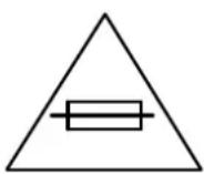
- Use to rated Fuse.
- Qualified person could be limited to maintenance, repair and replace of product.
SERVICE
Bridge series order to satisfy technical requirements and compact size, it could be limit to repair of SMT(Surface-Mount Technical) and program on site, immediately.
Please request to repair if products have a problem
Bridge RS 16x16
Bridge RS 16x16 is supporting 8x8 SDI input/output of video as "Routing Switcher".
A this model recognizes SD, HD and 3Gb/s SDI signal automatically change, It has the dual power supply and Reclocking function built-in.
And input state display. APC function(Control by RS422 communication of PC), button Lock function for the convenience of the user.
1. Feature
- Support SMPTE 292M, SMPTE 344M, SMPTE 259M, SMPTE 424M
- Re-clocking
- Multi-Rate SDI (143M, 177M, 270M, 340M, 540M, 1.485G, 1.485/1.001G, 2.97G)
- 3G/HD/SD-SDI 16 in x 16 out
- Auto equalizing (HD grade : compensate for up to 100m, SD : up to 300m of Belden 1694 Cable )
- RS-422 deck control ports (RJ45,)
- DC12V 3.33A Power supply included
- TCP/IP Network control ports (RJ45)
2. Name and function

그림 2-1 전면부
- LED : POWER1, POWER 2, REFERENCE, REMOTE
a. POWER1 :: Power supply input status of Power1 is shown.
b. POWER2 : Power supply input status of Power2 is shown.
c. REFERENCE : Reference input status is shown. (B.B, Tri-Level)
d. REMOTE: When controlling by communication, it's switched on and off.
- INPUT: An input signal presence is shown by an LED by 16 of input select button.
(Complete connection : LED ON, No connection : LED flicker)
- OUTPUT : 16 of output select button
- ENABLE : When it's pushed for more than 1 second, LED On.
When lighting up, it's possible to control the item number 2,3
When pushing it again, it's turned off.
- FUNCTION : In Out setting is preserved or, when import, it's used.
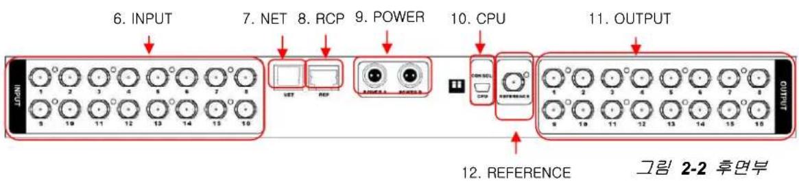
- INPUT : 16 of Input BNC
- NET : Support to TCP/IP NETWORK
- RCP : Support to RCP by RS-422 Communication(A protocol is in an attachment ..)
- POWER : 2 of 12V adapter power supply input (can be spare)
- CPU : CPU CONSOL MINI USB TYPE
- OUTPUT : 16 of output BNC
- REFERENCE : Tri-level or 1 of Black Burst input
3. Way of use


1. Input / Output Setting
To connect the Video source to the INPUT BNC.
To connect the OUTPUT BNC to the input of the equipment that I want try to send the display equipment and source.
The ON cases the ENABLE button, press the ENABLE button for more than 1 second.
Select the same OUTPUT button and OUTPUT BNC number which is connected to the equipment that I want try to send the display equipment and source.
Screen output or by pressing the same button as the other INPUT BNC and concatenate number and transmitted to the appropriate equipment. If all of the settings are completed, ON causes the ENABLE button press again the ENABLE button.※ equipment seen has to be selected after selecting the input button the output button first in such a way as above because it is designed as an output reference.
2. FUNCTION KEY Operating
As the ENABLE button state is on, and press the FUNCTION KEY, It means that four right buttons and four left buttons are ON.
(However, should a state of being turned ON ENABLE button.)
The left side is a save button, the right side data load button. Save and load data is possible up to four each. If select the left button to become saved in the appropriate number.
Press the right button to become loaded the value of the corresponding number, it changed into the initial state. (The input port is to the first port of loading values reveal.)
3. Notices
This device button after selecting the first output in the same way as above because it is designed to be output should be selected based on the input buttons. Additionally, If the ENABLE button is ON, it does not communicate.
4. Signal Characteristic
1. HD-SDI Properties

HD-SDI IN SIGNAL

line
| Parameter | Value | |-------------------------|-----------| | Eye Amplitude | 817 mV | | Eye Rise Time | 97 ps | | Eye Rise Time | 105 ps | | Eye Rise Fall | 8 ps | | Eye Rise Overshoot | 16 % | | Eye Wall Overshoot | 29 % | | P-P Jitter 1 | 73 ps | | P-P Jitter 2 | 66 ps | | Approx Cable HDI | 0 m | | Cable Level HDI | 0.00 dB | | Source Level HDI | 752 mV |HD-SDI OUT SIGNAL
HD-SDI Serial Digital Video
| Connector | 75Ω BNC |
| Signal level | 800mV ± 10% |
| DC offset | 0V ± 0.5V |
| Rise and fall time | < 270ps (20% to 80% amplitude) |
| Overshoot | <10% of amplitude |
| Timing Jitter | <1 UI |
| Alignment Jitter | <0.2UI |
2. SD-SDI Properties

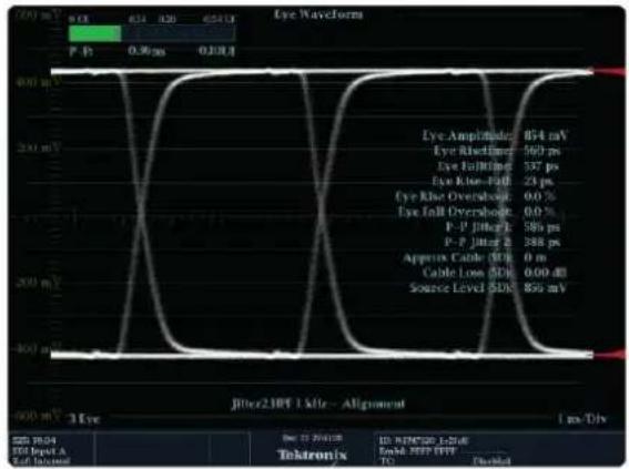
SD-SDI IN SIGNAL
line
| Parameter | Value | |-------------------------|-----------| | Eye Amplitude | 854 mV | | Eye Rhythm | 560 ps | | Eye Fibrillation | 337 ps | | Eye Knee-Pall | 23 ps | | Eye Knee Overshoot | 0.0 % | | Eye Fall Overshoot | 0.0 % | | P-P Jitter | 581 ps | | P-P Jitter 2 | 388 ps | | Approx Cable | 50 μs | | Cable Loco | 0.00 dB | | Source Level | 50 kV |SD-SDI OUT SIGNAL
SD-SDI Serial Digital Video
| Connector | 75Ω BNC |
| Signal level | 800mV ± 10% |
| DC offset | 0V ± 0.5V |
| Rise and fall time | 400~800ps(20% to 80% amplitude) |
| Overshoot | <10% of amplitude |
| Timing Jitter | <0.2 UI |
| Alignment Jitter | <0.2UI |
5. Specification
| Connections | |
| SDI Video Input | SD/HD-SDI, 3Gb/s SDI and ASI. X16 (BNC) |
| SDI Video Output | SD/HD-SDI, 3Gb/s SDI and ASI with SDI re-clocking. X16 (BNC) |
| Remote Control | RS-422 (RJ45) |
| Reference Input | B.B , TRI x1 (BNC) |
| NET | TCP/IP (RJ45) |
| Electrical | |
| Voltage | 90 ~ 240V AC 50/60Hz |
| Power Dissipation | < 28W(12V DC, 3.33A) |
| Temperature | 0 ~ 40°C |
| Physical | |
| Size | 481mm x 43mm x 133mm(W x H x D) |
| Weight | 1.85Kg |
| Standards | |
| SD Format Support | 625/25 PAL and 525/29.97 NTSC. |
| HD Format Support | 1080p23.98, 1080PsF23.98, 1080p24, 1080PsF24, 1080p25, 1080PsF25, 1080p29.97, 1080PsF29.97, 1080p30, 1080PsF30, 1080i50, 1080i59.94, 1080i60, 1080p50, 1080p59.94, 1080p60, 720p23.98, 720p24, 720p25, 720p29.97, 720p30, 720p50, 720p59.94, 720p60. |
| SDI Compliance | SMPTE 259M, SMPTE 292M, SMPTE 296M, SMPTE 310M, SMPTE 425M-A, SMPTE 425M-B |
| SDI Video Sampling | 4:2:2 and 4:4:4. |
| SDI Video Rates | SDI video connections are switchable between standard definition, high definition and 2K. SDI switches between 270 Mb/s standard definition SDI, 1.5 Gb/s HD-SDI and 3 Gb/s HD SDI. |
| SDI Auto Switching | Automatically selects between SD-SDI, HD-SDI, 3 Gb/s SDI and DVB-ASI on each input so that each input can be running a different television standard. |
6. Attach
Cable connection
RJ-45 PIN 설명

natural_image
Close-up of a transparent plastic electrical connector with multicolored wires (no visible text or symbols)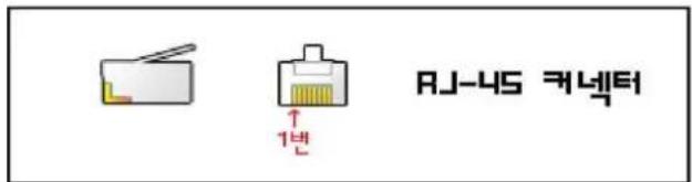
natural_image
Abstract vertical bar pattern with alternating colored bars (no text or symbols)RJ-45
1 TX+ 7 RX+
2 TX- 8 RX-
※ It consists of PIN MAP like the top, when connecting with RCP, you should manufacture a LAN cable by 1:1
※ When ENABLE is, the main body can't make ENABLE RCP.
If the main body will be ENABLE even if RCP ENABLE will be, RCP will be a disable.
※ REMOTE LED of RCP is flicker every time when data is received by the main body.

Brand : Digital Forecast
Model : RS 16*16
Category : Router