
IPOE-171-95W - PoE Injector Planet - Free user manual and instructions
Find the device manual for free IPOE-171-95W Planet in PDF.


| Product Type | Industrial 802.3bt Multi-Gigabit PoE++ Injector |
| Model | IPOE-171-95W |
| Dimensions (W x D x H) | 135 x 87.8 x 32 mm |
| Weight | 443 g |
| Enclosure | Metal case, IP30 slim type |
| Power Input | DC 12~54V, 6A max. |
| Power Consumption | 120 watts max. |
| PoE Standard | IEEE 802.3bt Type 4 PSE |
| PoE Power Output Budget | DC 54V / 95-watt PoE via 4-pair; DC 54V / 30-watt PoE via 2-pair |
| PoE Power Output (max) | 89.5W @ 1m cable (DC 24~48V input); 60W @ 1m cable (DC 12V input) |
| Data Rate | 10M/100M/1G/2.5G/5Gbps |
| Network Cable | Twisted-pair up to 100m; Cat. 5e, 6, 6A for 1G/2.5G/5G |
| LED Indicators | P1 (Green), P2 (Green), Alarm (Red), PoE-in-Use (Amber), PoE Usage x3 (Amber) |
| ESD Protection | 6KV DC |
| Operating Temperature | -40 ~ 75°C |
| Storage Temperature | -40 ~ 85°C |
| Operating Humidity | 5 ~ 90% (non-condensing) |
| Mounting | DIN-rail kit or wall-mount ear |
| Alarm Relay | 1 relay output for power failure; 1A @ DC 24V |
| Regulatory Compliance | FCC Part 15 Class A, CE |
| Package Contents | Injector x1, User's manual x1, Dust cap x2, Wall-mount kit x1 |
Frequently Asked Questions - IPOE-171-95W Planet
User questions about IPOE-171-95W Planet
0 question about this device. Answer the ones you know or ask your own.
Ask a new question about this device
Download the instructions for your PoE Injector in PDF format for free! Find your manual IPOE-171-95W - Planet and take your electronic device back in hand. On this page are published all the documents necessary for the use of your device. IPOE-171-95W by Planet.
USER MANUAL IPOE-171-95W Planet
Industrial 802.3bt Multi-Gigabit PoE++ Injector
IPOE-171-60W/IPOE-171-95W
User's Manual
Table of Contents
- Package Contents.... 3
- Product Specifications 4
- Product Outlook 7
3.1 Product Outlook....7
3.2 Industrial PoE++ Injector Upper Panel....10
3.3 Wiring the Power Inputs....10
3.4 Wiring the Fault Alarm Contact 12
- Mounting Installation ....13
4.1 DIN-rail Mounting Installation ....13
4.2 Wall-mount Plate Mounting....13
4.3 Side Wall-mount Plate Mounting....14
4.4 Grounding the Device....14
- Hardware Installation....15
5.1 Before Installation....15
5.2 IPOE-171-60W/IPOE-171-95W Installation 15
- Customer Support....17
1. Package Contents
Thank you for purchasing PLANET IPOE-171 Single-port 802.3bt PoE++ Injector series. In the following section, the term "IPOE-171 Series" means the IPOE-171-60W or IPOE-171-95W.
| Model LAN | Port Speed PoE Standard PoE Budget | |
| IPOE-171-60W | 10M/100M/1G/2.5G/5Gbps | IEEE 802.3at/bt 60 watts |
| IPOE-171-95W | 10M/100M/1G/2.5G/5Gbps | IEEE 802.3at/bt 95 watts |
Please unpack the box of the device carefully, and the box should contain the following items:
- 802.3bt PoE injector x 1
- User's manual x 1
- Dust cap x 2
- Wall-mount kit x 1
If any item is found missing or damaged, please contact your local reseller for replacement.
2. Product Specifications
| Product IPOE-171-60W IPOE-171-95W | |||
| Hardware Specifications | |||
| Interface | Input Port | 1 x RJ45 STPData In | |
| Output Port | 1 x RJ45 STPPoE (Data + Power) Out | ||
| Input Power Terminal Block | 1 | ||
| Network Cable* | Twisted-pair cable up to 100 meters (328ft)10BASE-T: 4-pair UTP Cat. 3, 4, 5, 5e, 6, 6A100BASE-TX: 4-pair UTP Cat. 5, 5e, 6, 6A1G/2.5G: 4-pair UTP Cat. 5e, 6, 6A5G: 4-pair UTP Cat. 6, 6A | ||
| LED Indicators | System: Power 1 (Green),Power 2 (Green),Alarm (Red)PoE Port: PoE-in-Use x 1 (Amber)PoE Usage: PoE Usage x 3 (Amber) | ||
| Data Rate 10M/100M/1G/2.5G/5Gbps | |||
| Dimensions(W x D x H) | 135 x 87.8 x 32 mm | ||
| ESD Protection 6KV DC | |||
| Enclosure Metal case | |||
| Weight 406g 443g | |||
| Power Requirements DC | 48~54V, 2A max. DC | 12~54V, 6A max. | |
| Unit Output Voltage DC | 45~53V DC 54V | ||
| Power Consumption 75 | watts max. | 120 watts max. | |
| No. of devices that can be powered | 1 | ||
| Installation DIN-rail kit or wall-mount ear | ||
| Alarm | Provides one relay output for power failure Alarm Relay current carry ability: 1A @ DC 24V | |
| Enclosure IP30 slim type metal case | ||
| Power over Ethernet | ||
| PoE Standard | IEEE 802.3bt Type 3 PSE | IEEE 802.3bt Type 4 PSE |
| PoE Power Output Budget | DC 50~53V / 60-watt PoE via 4-pair DC 45~53V / 30-watt PoE via 2-pair | DC 54V / 95-watt PoE via 4-pair DC 54V / 30-watt PoE via 2-pair |
| PoE Power Output | Max. 60W@1m cable Max. 51W@100m cable | -DC 24V~48V input: Max. 89.5W@1m cable Max. 75W@100m cable -DC 12V input: Max. 60W@1m cable Max. 52W@100m cable |
| PoE Power Supply Type | End-span + Mid-span | |
| Power Pin Assignment | Pair 1 End-span: 1/2 (-), 3/6 (+) Pair 2 Mid-span: 4/5 (+), 7/8 (-) | |
| PoE Mode | Standard mode Legacy and Force mode | |
| Standards Conformance | ||
| Standards Compliance | IEEE 802.3 10BASE-T Ethernet IEEE 802.3u 100BASE-TX Fast Ethernet IEEE 802.3ab 1000BASE-T Gigabit Ethernet IEEE 802.3bz 2.5G/5GBASE-T IEEE 802.3bt 4-pair Power over Ethernet IEEE 802.3at Power over Ethernet Plus | |
| Regulatory Compliance | FCC Part 15 Class A, CE | |
| Environment | ||
| Operating Temperature | -40 ~ 75 degrees C | |
| Storage Temperature | -40 ~ 85 degrees C | |
| Operating Humidity 5 ~ | 90%, relative humidity, non-condensing | |
| Storage Humidity 5 ~ | 90%, relative humidity, non-condensing | |

Caution
- As IEEE 802.3bt device provides high power, please use high-quality network cable and RJ45 connector.
- The maximum PoE output power depends on the cable length, the quality of cable, and DC input voltage.
3. Product Outlook
3.1 Product Outlook
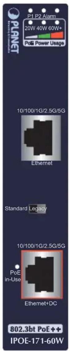

Figure 1: IPOE-171-60W outlook Figure 2: IPOE-171-95W outlook
IPOE-171-60W LED Indicators:
| LED Color Function | ||
| P1 Green Lights to indicate power 1 has power. | ||
| P2 Green Lights to indicate power 2 has power. | ||
| Alarm Red | Lights to indicate either power 1 or power 2 has no power. | |
| PoE-in-Use | Amber Lights to indicate the device is providing PoE power. | |
| PoE Usage | Amber | ● Monitor DC input voltage:When user powers on IPOE-171-60W, the injector will detect the DC input voltage and then PoE Usage LED will flash three times.20W: Flashing three times means the DC input voltage is 48~50.9V.40W: Flashing three times means the DC input voltage is 51~52.9V.● Monitor power usage:20W:1. Off to indicate the PoE usage is less than 9W.2. Blinks to indicate that the PoE usage is around 10W to 19W.3. Lights to indicate the PoE usage is more than 20W.40W:1. Blinks to indicate that the PoE usage is around 30W to 39W.2. Lights to indicate the PoE usage is more than 40W.60W+:1. Blinks to indicate that the PoE usage is around 50W to 59W.2. Lights to indicate the PoE usage is at the maximum. |
IPOE-171-95W LED Indicators:
| LED Color Function | |
| P1 Green Lights to indicate power 1 has power. | |
| P2 Green Lights to indicate power 2 has power. | |
| Alarm Red | Lights to indicate either power 1 or power 2 has no power. |
| PoE-in-Use | Amber Lights to indicate the device is providing PoE power. |
| PoE Usage | Amber | 30W:1. Off to indicate the PoE usage is less than 14W.2. Blinks to indicate that the PoE usage is around 15W to 29W.3. Lights to indicate the PoE usage is more than 30W.60W:1. Blinks to indicate that the PoE usage is around 45W to 59W.2. Lights to indicate the PoE usage is more than 60W.90W+:1. Blinks to indicate that the PoE usage is around 75W to 89W.2. Lights to indicate the PoE usage is at the maximum. |
PoE Mode of IPOE-171 series:
| PoE Mode | Description |
| Standard (Default) | The standard mode is chosen to provide power to the PD devices that follow the IEEE 802.3at/bt standard. |
| Legacy | The legacy mode supports Ultra PoE. It is chosen to provide power to the PD devices that do not fully follow the IEEE 802.3at/bt standard. |
| Force | WarningIf the output power of injector is less than 1 watt when in the Legacy mode, after 20 seconds, the Force mode will be enabled. When the Force mode is enabled, it will provide PD with a maximum of 60 watts. If the output power of injector is less than 1 watt when in the Force mode, after 2 seconds, the Legacy mode will be enabled. |

Note
After changing the PoE mode, please power off and then on the PoE injector to make the change effective.
3.2 Industrial PoE++ Injector Upper Panel
The upper panel of the IPOE-171 series has one terminal block connector where there are two DC power inputs.
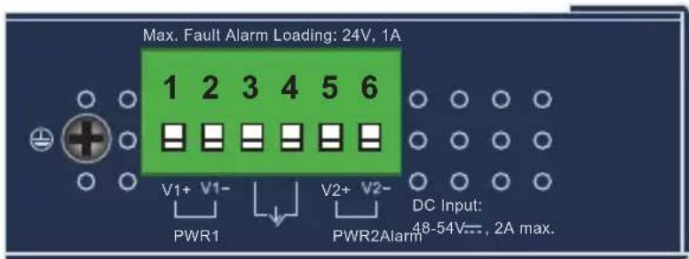
Figure 3: IPOE-171-60W upper panel.

Figure 4: IPOE-171-95W upper panel.
3.3 Wiring the Power Inputs
The 6-contact terminal block connector on the top panel of the IPOE-171 series is used for two DC redundant power inputs. Please follow the steps below to insert the power wire.
Step 1: Insert Positive/Negative DC power wires into Contacts 1 and 2 for POWER 1, or 5 and 6 for POWER 2.

Figure 5: Power input pins.
Step 2: Tighten the wire-clamp screws for preventing the wires from loosening.

123456
Power 1 Alarm Power 2
+ - + -
Figure 6: PWR1 & PWR2 Pins of Terminal Block.

Note
-
The wire gauge for the terminal block should be in the range between 12 24 AWG.
-
As the DC input connector of the IPOE-171 series is polarity protected, connecting Positive/Negative DC power wires to the wrong pins will not damage the unit.
3.4 Wiring the Fault Alarm Contact
The fault alarm contacts are in the middle of the terminal block connector as the picture shows below. After inserting the wires, the IPOE-171 series will detect the fault status of the power failure and then form an open circuit. The following illustration shows an application example for wiring the fault alarm contacts.
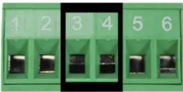
Figure 7: Fault Pin of Terminal Block.

Note
- The wire gauge for the terminal block should be in the range between 12 \~ 24 AWG.
- Alarm relay circuit accepts up to 24V, max. 1A currents.

Figure 8: Fault Alarm Contact
4. Mounting Installation
This section describes how to install the industrial device and make connections to it. Please read the following sections and perform the procedures in the order being presented.

Note
In the installation steps below, this manual uses PLANET Industrial Switch as an example. The steps for PLANET Industrial Slim-type Switch, Industrial Media/Serial Converter and Industrial PoE devices are similar.
4.1 DIN-rail Mounting Installation


4.2 Wall-mount Plate Mounting
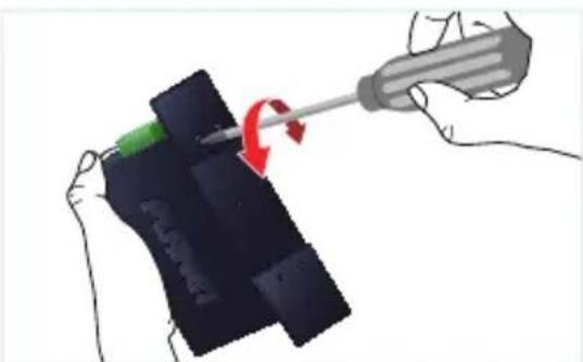

4.3 Side Wall-mount Plate Mounting
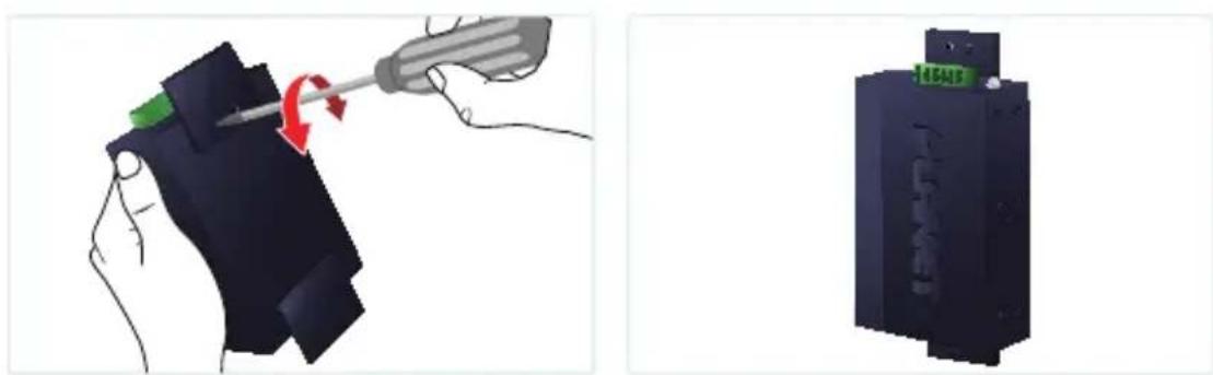
* The above pictures are for illustration only.
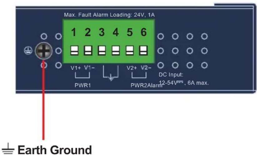
4.4 Grounding the Device
Users MUST complete grounding wired with the device; otherwise, a sudden lightning could cause fatal damage to the device.
5. Hardware Installation
The following section describes the hardware features of the IPOE-171 series. Before connecting any network device to it, please read this chapter carefully.
5.1 Before Installation
Before your installation, it is recommended to check your network environment. If there is any IEEE 802.3bt device that needs to be powered on and works normally, the IPOE-171 series is the solution that supplies power to this Ethernet device conveniently and easily. If there is difficulty in finding a power socket for the AC-DC conn to your non-IEEE 802.3at/bt networked device, the IPOE-171 series with POE-173S/IPOE-173S can supply DC power to this Ethernet device conveniently and easily.

Note
- In the installation steps below, this manual uses the IPOE-171-60W as an example. Except the input voltage, the steps for the IPOE-171-95W are similar.
- Note that the input power range of the IPOE-171-60W is 48 \~ 54V DC and the input power range of IPOE-171-95W is 12 \~ 54V DC.
5.2 IPOE-171-60W/IPOE-171-95W Installation
- Connect the power ranging from 12V/48V DC to 54V DC to the 6-pin terminal block of the IPOE-171-60W/IPOE-171-95W. The power LED will be steadily on.
- Connect a standard Ethernet cable from an Ethernet switch or PC workstation to "Ethernet" port of the IPOE-171-60W/IPOE-171-95W.
-
Connect the long cable to the "Ethernet+DC" port.
-
The IPOE-171-60W/IPOE-171-95W can directly connect with any IEEE 802.3at/bt end-nodes, such as PTZ (pan, tilt & zoom) IP cameras, PTZ speed dome cameras, color touch screens, Voice over IP (VoIP) telephones and multi-channel wireless LAN access points which support IEEE 802.3at/bt In-line Power over Ethernet port.
![graph LR A["Power Supply"] --> B["DC Input"] B --> C["Data"] C --> D["Industrial Switch"] D --> E["75°C -40°C"] E --> F["Data"] F --> G["PoE PTZ IP Camera"] style E fill:#f9f,stroke:#333 style F fill:#ccf,stroke:#333 linkStyle 0 stroke:#000,stroke-width:2px linkStyle 1 stroke:#000,stroke-width:2px l…](/content/2026/05/900956/images/e811334b7e67c8b037827ec686ed1cc96d7cac4ffb15e73579ca631d53d084ad.jpg)
Figure 9: Architecture of connected IEEE 802.3at/bt device
Once the IPOE-171-60W detects the existence of an IEEE 802.3at/bt device, the PoE-in-Use LED indicator will be steadily on to show it is providing power.

Note
-
According to IEEE 802.3at/bt Power over Ethernet, the IPOE-171 Series will not inject power to the cable if not connected to IEEE 802.3at/bt device. But the Force mode is exceptional.
-
Depending on the length of cable, the PoE power which PD receives is different.
6. Customer Support
Thank you for purchasing PLANET products. You can browse our online FAQ resource at the PLANET Web site first to check if it could your issue. If you need more support information, please contact PLANET support team.
PLANET online FAQs: https://www.planet.com.tw/en/support/faq
Support team mail address: support@planet.com.tw
FCC Statement
NOTE: This equipment has been tested and found to comply with the limits for a Class A digital device, pursuant to part 15 of the FCC Rules. These limits are designed to provide reasonable protection against harmful interference when the equipment is operated in a commercial environment. This equipment generates, uses, and can radiate radio frequency energy and, if not installed and used in accordance with the instruction manual, may cause harmful interference to radio communications. Operation of this equipment in a residential area is likely to cause harmful interference in which case the user will be required to correct the interference at his own expense.
ISEDC Statement
CAN ICES-003(A) / NMB-003(A)
This device complies with Industry Canada license-exempt RSS standard(s).
Operation is subject to the following two conditions: (1) this device may not cause interference, and (2) this device must accept any interference, including interference that may cause undesired operation of the device.
This device is compliant with Class A of CISPR 32. In a residential environment this equipment may cause radio interference.
WEEE Warning

To avoid the potential effects on the environment and human health as a result of the presence of hazardous substances in electrical and electronic equipment, end users of electrical and electronic equipment should understand the meaning of the crossed-out wheeled bin symbol. Do not dispose of WEEE as unsorted municipal waste and have to collect such WEEE separately.
- INDUSTRIAL 802.3BT MULTI-GIGABIT POE++ INJECTOR
- IPOE-171-60W/IPOE-171-95W
- TABLE OF CONTENTS
- PACKAGE CONTENTS
- PRODUCT SPECIFICATIONS
- PRODUCT OUTLOOK
- 3.1 PRODUCT OUTLOOK
- IPOE-171-60W LED INDICATORS
- 3.2 INDUSTRIAL POE++ INJECTOR UPPER PANEL
- 3.3 WIRING THE POWER INPUTS
- 3.4 WIRING THE FAULT ALARM CONTACT
- MOUNTING INSTALLATION
- 4.1 DIN-RAIL MOUNTING INSTALLATION
- 4.2 WALL-MOUNT PLATE MOUNTING
- 4.3 SIDE WALL-MOUNT PLATE MOUNTING
- 4.4 GROUNDING THE DEVICE
- HARDWARE INSTALLATION
- 5.1 BEFORE INSTALLATION
- 5.2 IPOE-171-60W/IPOE-171-95W INSTALLATION
- CUSTOMER SUPPORT
- FCC STATEMENT
- ISEDC STATEMENT
- WEEE WARNING
Brand : Planet
Model : IPOE-171-95W
Category : PoE Injector