
MG-110 - Network gateway Planet - Free user manual and instructions
Find the device manual for free MG-110 Planet in PDF.


| Product Type | 1-Port RS232/422/485 Modbus Gateway |
| Model | MG-110 |
| Dimensions (W x D x H) | 97 x 70 x 26 mm |
| Weight | 184 g |
| Power Supply | External AC-DC adapter, 5V DC, 2A max |
| Power Consumption | 5.5 watts (max) |
| Serial Interface | 1 x DB9 male, supports RS232, RS422, 2-wire RS485, 4-wire RS485 |
| Baud Rate | 50 bps to 921600 bps |
| Ethernet Interface | 1 x 10/100BASE-TX RJ45 with auto MDI/MDI-X |
| Supported Protocols | Modbus TCP, Modbus RTU, Modbus ASCII, IP, ARP, DHCP, DNS |
| Operation Modes | RTU Master, RTU Slave, ASCII Master, ASCII Slave; Master: up to 32 TCP slaves; Slave: up to 32 TCP masters |
| Management Interfaces | Web, Telnet, Windows VCOM Utility, SNMP v1/v2c, PLANET Smart Discovery |
| IP Version | IPv4 |
| Operating Temperature | -10 to 60°C |
| Storage Temperature | -10 to 70°C |
| Humidity | 5 to 95% (non-condensing) |
| Installation Options | Standalone, wall-mount, DIN-rail (optional kit), slide-in media chassis (MC-700/1500) |
| LED Indicators | PWR (green), Serial TX/RX (green blink), TP Link/Active (green) |
| Reset Button | < 5 sec: reboot; > 5 sec: factory defaults |
| Default IP Address | 192.168.0.100 |
| Default Username / Password | admin / admin |
| Regulatory Compliance | FCC Part 15 Class A, CE Class A, RoHS |
Frequently Asked Questions - MG-110 Planet
User questions about MG-110 Planet
0 question about this device. Answer the ones you know or ask your own.
Ask a new question about this device
Download the instructions for your Network gateway in PDF format for free! Find your manual MG-110 - Planet and take your electronic device back in hand. On this page are published all the documents necessary for the use of your device. MG-110 by Planet.
USER MANUAL MG-110 Planet
User's Manual
RS232/RS422/RS485
Modbus Gateway Series
MG-110 / MG-115AT / MG-120

Trademarks
Copyright © PLANET Technology Corp. 2020.
Contents are subject to revision without prior notice.
PLANET is a registered trademark of PLANET Technology Corp. All other trademarks belong to their respective owners.
Disclaimer
PLANET Technology does not warrant that the hardware will work properly in all environments and applications, and makes no warranty and representation, either implied or expressed, with respect to the quality, performance, merchantability, or fitness for a particular purpose. PLANET has made every effort to ensure that this User's Manual is accurate; PLANET disclaims liability for any inaccuracies or omissions that may have occurred.
Information in this User's Manual is subject to change without notice and does not represent a commitment on the part of PLANET. PLANET assumes no responsibility for any inaccuracies that may be contained in this User's Manual. PLANET makes no commitment to update or keep current the information in this User's Manual, and reserves the right to make improvements to this User's Manual and/or to the products described in this User's Manual, at any time without notice.
If you find information in this manual that is incorrect, misleading, or incomplete, we would appreciate your comments and suggestions.
FCC Warning
This equipment has been tested and found to comply with the limits for a Class A digital device, pursuant to Part 15 of the FCC Rules. These limits are designed to provide reasonable protection against harmful interference when the equipment is operated in a commercial environment. This equipment generates, uses, and can radiate radio frequency energy and, if not installed and used in accordance with the Instruction manual, may cause harmful interference to radio communications. Operation of this equipment in a residential area is likely to cause harmful interference in which case the user will be required to correct the interference at his own expense.
CE Mark Warning
This is a Class A product. In a domestic environment, this product may cause radio interference, in which case the user may be required to take adequate measures.
Energy Saving Note of the Device
This power required device does not support Standby mode operation. For energy saving, please remove the power cable to disconnect the device from the power circuit. In view of saving the energy and reducing the unnecessary power consumption, it is strongly suggested to remove the power connection for the device if this device is not intended to be active.
WEEE Warning

To avoid the potential effects on the environment and human health as a result of the presence of hazardous substances in electrical and electronic equipment, end users of electrical and electronic equipment should understand the meaning of the crossed-out wheeled bin symbol. Do not dispose of WEEE as unsorted municipal waste and have to collect such WEEE separately.
Revision
PLANET MG-11x Series User's Manual
Model: MG-110 / MG-115A / MG-120
Revision: 1.0 (August, 2020)
Part No: EM-MG-11x_v1.0
TABLE OF CONTENTS
1. INTRODUCTION .... 5
1.1 Packet Contents ....5
1.2 Product Description....6
1.3 How to Use This Manual .... 10
1.4 Product Features....11
1.5 Product Specifications....12
2. INSTALLATION .... 15
2.1 Hardware Description....15
2.1.1 Physical Dimensions .... 15
2.1.3 Front / Top Panel 19
2.1.4 LED Indications ....20
2.1.5 Rear Panel 20
2.1.6 Power Information: 21
2.1.7 Serial Port Pin Define ....22
2.2 Installing the Modbus Gateway ....23
2.2.1 Installation Steps 23
2.2.2 Wall-mount Installation 24
2.2.3 Media Chassis Installation (MG-110/115A) 25
2.2.4 Optional DIN-rail Installation....25
3. MODBUS GATEWAY MANAGEMENT....27
3.1 Requirements 27
3.2 Web Management ....28
3.2.1 Logging in to the Modbus Gateway....28
3.3 Remote Management....30
3.4 PLANET Smart Discovery Utility .... 31
3.5 Getting Started with MB VCOM Utility....33
3.5.1 Installation of MB VCOM Utility ....33
3.5.2 Searching Modbus Gateway .... 33
4. WEB CONFIGURATION....35
4.1 Main Web Page....37
4.2 System....38
4.2.1 System....38
4.2.2 Port 40
4.2.3 Device....41
4.2.4 Time....41
4.2.5 Console....42
4.2.6 Email....42
4.3 Accessible IP 44
4.4 Network 45
4.5 Modbus Gateway 46
4.5.1 Serial setup....46
4.5.2 Operation mode....47
4.5.2.1 Disable mode....47
4.5.2.2 RTU Slave mode....48
4.5.2.3 RTU Master mode....49
4.5.2.4 ASCII Slave mode....49
4.5.2.5 ASCII Master mode....50
4.5.3 MB COM .... 50
4.5.4 Modbus Config 51
4.5.4.1 Router 51
4.5.4.2Mapping....52
4.5.4.3 Parameters....54
4.5.5 Priority Control....54
4.5.5.1 Master 54
4.5.5.2TCP 55
4.5.5.3 Request....55
4.6 SNMP Setup....56
4.7 Maintenance....57
4.7.1 Change Password ....57
4.7.2 Load Default 57
4.7.3 Firmware Update ....58
4.8 Save and Restart....59
5. SOFTWARE MB VCOM UTILITY 60
5.1 Installing the VCOM Utility....60
5.2 Search Devices 63
5.3 COM Port Mapping....64
1. INTRODUCTION
Thank you for purchasing PLANET MG-110/MG-115A/ MG-120 Modbus Gateway. "Modbus Gateway" is used as an alternative name in this User's Manual.
| MG-110 | 1-Port RS232/422/485 Modbus Gateway |
| MG-115A | 1-Port RS232/422/485 Modbus Gateway with 1-Port 100BASE-FX SFP |
| MG-120 | 2-Port RS232/422/485 Modbus Gateway |
"Modbus Gateway" mentioned in this Guide refers to the MG-110/MG-115A/ MG-120.
1.1 Packet Contents
Open the box of the Modbus Gateway and carefully unpack it. The box should contain the following items:
| The Modbus Gateway x 1 | User's Manual x 1 |
| External AC-DC Power Adapter x 1 | |
If any of these are missing or damaged, please contact your dealer immediately; if possible, retain the carton including the original packing material, and use them again to repack the product in case there is a need to return it to us for repair.
1.2 Product Description
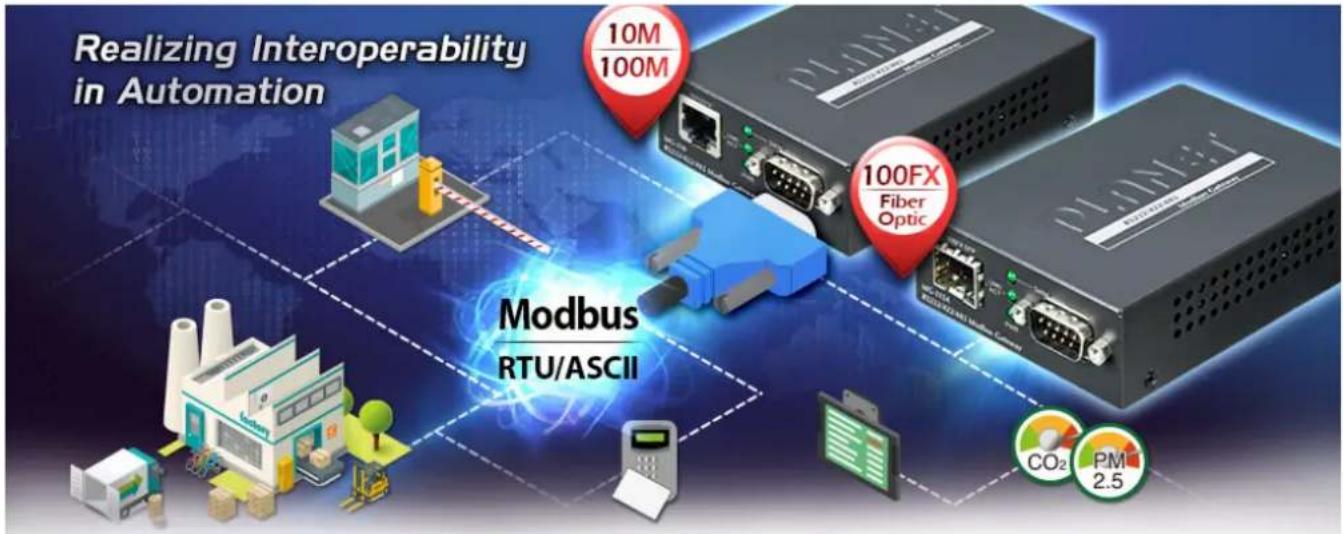
Standard Modbus TCP/RTU/ASCII Network Integration
PLANET MG-11x 1-port RS232/422/485 Modbus Gateway Series supports the standard Modbus Protocol, which makes it possible for converting any Modbus Protocols between Modbus TCP, Modbus RTU, and Modbus ASCII for all supported hardware interfaces. Its serial protocol can be used for industrial automation where SCADA or HMI system is in place. Moreover, its network integration can be upgraded from the SNMP network to the automated Modbus TCP network, which brings interconnection over Ethernet longer distances, thus making a network infrastructure more flexible.

A Conversion Bridge for Flexible Network Deployment
The MG-11x Series can be a conversion bridge between the equipment with the Modbus RTU/ASCII Protocol and the administrator workstations that run the Modbus TCP/IP Protocol. The RS232/422/485 serial interface of the MG-11x Series provides the Modbus RTU/ASCII operation mode and various baud rate options to meet the demand of integration between the Modbus TCP/IP Protocol, Modbus RTU Master/Slave Protocol and Modbus ASCII Master/Slave Protocol.
![graph LR A["Modbus TCP/IP Ethernet"] -->|Modbus TCP/IP 10/100TX UTP| B["MG-110"] B -->|Serial Cable RS232/422/485| C["Equipment"] D["Workstation with SCADA"] --> A E["RTU Slave 32 TCP Masters"] --> B F["ASCII Slave 32 TCP Masters"] --> B G["RTU Master 32 TCP Slaves"] --> B H["ASCII Master"] --> B I[…](/content/2026/05/900935/images/0fef2ed635445ce6fbbe95de62f8e852a1a67bd5c93ca938d7f7cd23fc675b43.jpg)
![graph TD A["Modbus TCP/IP Ethernet"] -->|Modbus TCP/IP 10/100TX UTP| B["MG-120"] B --> C["Serial Cable RS232/422/48S"] C --> D["Modbus Equipment"] E["Workstation with SCADA"] --> B F["RTU Slave 32 TCP Masters"] --> B G["ASCII Slave 32 TCP Slaves"] --> B H["RTU Master 32 TCP Slaves"] --> B I["ASCII M…](/content/2026/05/900935/images/b9710a32665dd03030f2049c2218de10c5d739bae771c6c7d362e9fc914da235.jpg)
The advantage of having the MG-11x Series is to assist users to build an environment between the Modbus TCP Protocol and the Modbus RTU/ASCII Protocol easily, thus offering an application solution to the control equipment without Ethernet ports, and the control equipment can only control through a PC workstation or control panel.
In addition, the effective integration solution of Modbus Ethernet devices, Modbus serial equipment or multi Modbus master / slave in an hybrid network brings the following:
■ Master mode supports up to 32 TCP slave connection requests
■ Slave mode supports up to 32 TCP master connection requests
Differences between Serial Devices and Modbus Gateway
Serial Devices Server
![graph LR A["VCOM Utility + Serial Application"] --> B["Virtual COM port"] B --> C["ICS-110"] C --> D["Serial Port (RS232/422/485)"] D --> E["Serial Device"] C -->|RJ45 UTP| B style A fill:#f9f,stroke:#333 style B fill:#ccf,stroke:#333 style C fill:#cff,stroke:#333 style D fill:#ffc,stroke:#333 style…](/content/2026/05/900935/images/f6036802869a88f901a3ab409b9716e622605d4fcd9cb50678d72694e814a5b5.jpg)
Modbus Gateway
![graph LR A["Modbus TCP Application/SCADA"] -->|RJ45 UTP| B["MG-110"] B --> C["1 : 32 Serial Port (RS232/422/485)"] C --> D["Modbus RTU/ASCII Serial Devices"] D --> E["ID1~32"]](/content/2026/05/900935/images/9f35c8df8880896b3b8d7b597436d606721b9dda26dea4dfe80ac0db2702d8cc.jpg)
Remote Management
The MG-11x Series makes the connected Modbus RTU/ASCII equipment become IP-based facilities and is able to connect to the Modbus TCP/IP network via its R232/422/485 serial interface and 10/100BASE-TX RJ45 or 100BASE-FX Ethernet port. It provides a remote web management and telnet interface for efficient remote network management. The MG-11x Series also provides PLANET Modbus Gateway utility tool and supports PLANET Smart Discovery utility to help network administrator to easily get the current IP subnet address information or change the IP subnet address setting of the MG-11x Series.
Remote Management
![graph LR A["MB VCOM Utility"] --> B["Telnet"] B --> C["Web Browser"] C --> D["Modbus Gateway Series"] D --> E["TCP/IP"] E --> F["PLANT"]](/content/2026/05/900935/images/b45dab839a358f837969538e73e8314e1dd9fb49a0561fc853d52879772e540f.jpg)
Modbus Serial Port State Monitoring
The MG-11x Series shows the details of the total bytes transmitted and received on the RS232/422/485 serial interface, and the detailed total number of frames transmitted and received on the remote web/telnet management interface. This function allows network administrator to check the status and statistics of the MG-11x Series via the single RS232/422/485 serial interface.
Fiber-optic Link Capability Extends the Range of Network Deployment (Only MG-115A)
The maximum distance between two IP devices via Ethernet UTP cable is 100 meters. To flexibly extend the deployment range of Modbus gateway, the MG-115A's SFP slot supporting 100BASE-FX SFP modules and more can reach a transmission distance of up to 120km.
Easy Chassis Installation (Only MG-110/115A)
The MG-11x Series can be used as a stand-alone unit or as a slide-in module to the PLANET Media Converter Chassis (MC-700 and MC-1500 chassis series). The media chassis can assist in providing DC power to the MG-11x Series and can be DIN-rail or wall mounted for efficient use of cabinet space, without the need of replacing the existing serial equipment and software system.
Optional installation method

Media Chassis Installation

DIN-rail Installation

Wall-mount Installation
1.3 How to Use This Manual
This User's Manual is structured as follows:
Section 2, INSTALLATION
It explains the functions of the MG-11x Series and how to physically install the MG-11x Series.
Section 3, MODBUS GATEWAY MANAGEMENT
The chapter explains how to manage the MG-11x Series in different ways.
Section 4, WEB CONFIGURATION
It describes how to configure by web interface.
Section 5, SOFTWARE VCOM UTILITY
It describes how to use software VCOM in the Virtual COM mode.
1.4 Product Features
Serial Interface
One/Two DB9 interface supports RS232, 2-wire RS485, 4-wire RS485 and RS422 standards
■ Asynchronous serial data rates up to 921600bps
Ethernet Interface
■ 1-port 10/100BASE-TX RJ45 interface with auto MDI/MDI-X function
■ 1-port 100BASE-FX SFP slot (MG-115A)
▶ Management Function
Built-in IP-based Web interface and telnet interface for remote management
■ Software Protocol supports Modbus TCP, Modbus RTU, Modbus ASCII, IP, ARP, DHCP and DNS
■ Supports RTU Master, RTU Slave, ASCII Master, and ASCII Slave four serial operation modes via management interface
■ Master mode supports 32 TCP slave connection requests
■ Slave mode supports 32 TCP master connection requests
■ PLANET Modbus Gateway utility for finding client device on the network.
■ PLANET Smart Discovery utility automatically finds the client devices on the network
■ Firmware upgrade/configuration backup and restore via HTTP protocol
▶ Case and Installation
■ Compact size for easy Installation:
- Standalone - Wall mountable or DIN-rail mounting (optional accessory)
- Co-works with PLANET media chassis MC-700/1500. (Only MG-110/115A)
■ -10 to 60 degrees C operating temperature
■ Reset button for resetting to factory default
1.5 Product Specifications
| Product | MG-110 | MG-115A | MG-120 |
| Serial Interface | |||
| Serial Port | 1 x DB9 male | 2 x DB9 male | |
| Serial Standards | RS232/RS422/4-wire RS485/2-wire RS485 | ||
| Baud Rate (Data Rate) | 50bps to 921Kbps | ||
| Data Bits | 5, 6, 7, 8 | ||
| Stop Bit | 1, 1.5, 2 | ||
| Parity Type | Odd, Even, None, Space, Mark | ||
| Flow Control | RTS/CTS and DTR/DSR (RS232 only)XON/XOFF | ||
| Signals | RS232: TxD, RxD, RTS, CTS, DTR, DSR, DCD, GNDRS422: Tx+, Tx-, Rx+, Rx-, GND4-wire RS485: Tx+, Tx-, Rx+, Rx-, GND2-wire RS485: Data A (+), Data B (-), GND | ||
| Pin Assignment |  | ||
| Operation Mode | RTU Master/RTU Slave/ASCII Master/ASCII SlaveMaster mode: Supports up to 32 TCP slave connection requestsSlave mode: Supports up to 32 TCP master connection requests | ||
| Ethernet Interface | |||
| Ethernet Ports | 1 x RJ45 | 1 x SFP | 1 x RJ45 |
| Standard | 10/100BASE-TX | 100BASE-FX | 10/100BASE-TX |
| Distance | 100m | 2km to 120km, vary on SFP modules | 100m |
| ESD Protection | 6KV | ||
| Hardware | |||
| Installation | DIN-rail kit and wall-mount ear | ||
| Dimensions (W x D x H) | 97 x 70 x 26mm | 97 x 70 x 26mm | 97 x 70 x 26mm |
| Weight | 184 g | 185 g | 189g |
| LED Indicators | System: LinkTP/SFP Port: Link/ ActiveSerial Port: Active | ||
| Power Requirements | External Power Adaptor 5V DC, 2A max. | ||
| Power Consumption | 5.5 watts (max) | ||
| Mechanical Metal | |||
| Reset Button | < 5 sec: System reboot> 5 sec: Factory default | ||
| Management | |||
| Management Interfaces | Web managementTelnet Console managementWindows-based VCOM Utility managementSNMPv1, v2c / SNMP TrapUNI-NMS monitoringPLANET Smart Discovery Utility | ||
| IP Version | IPv4 | ||
| Operation Mode | RTU MasterRTU SlaveASCII MasterASCII Slave | ||
| Virtual COM Utility Platform Supports | Windows-based Only:Windows XPWindows Server 2003Windows 7Windows Server 2008Windows 8 (Must install the latest version of WinPcap)Windows Server 2012 (Must install the latest version of WinPcap)Windows 10 | ||
| Fault Alarm | Record: System log / SNMP trap | ||
| Time NTP | |||
| Security | Accessible IP (white list) | ||
| SNMP SNMP v1 and v2c | |||
| Standards Conformances | |||
| Regulatory Compliance | FCC Part 15 Class A,CE Certification Class A | ||
| Standards | IEEE 802.3 10BASE-T,IEEE 802.3u 100BASE-TX/100BASE-FXRFC 768 UDPRFC 793 TFTP RFC 791 IPRFC 792 ICMPRFC 854 TelnetRFC 958 NTPRFC 1908 SNMPv2cRFC 2068 HTTPRFC 2131 DHCP ClientEIA/TIA RS232/422/485 | ||
| Regulatory Approval RoHS | |||
| Compatible Media Converter Chassis | MC-700, MC-1500, MC-1500R | N/A | |
| Note. | Reset Button on the rear panel for resetting to factory default |
| Environment | |
| Operating Temperature | -10 ~ 60 degrees C |
| Storage Temperature | -10 ~ 70 degrees C |
| Humidity | 5 ~ 95% (non-condensing) |
2. INSTALLATION
This section describes the hardware features and installation of the Modbus Gateway' components on the desktop or rack. For easier management and control of the Modbus Gateway, familiarize yourself with its display indicators, and ports. Front panel illustrations in this chapter display the LED indicators. Before connecting any network device to the Modbus Gateway, please read this chapter completely.
2.1 Hardware Description
2.1.1 Physical Dimensions
■ MG-110: 94 x 70 x 26mm (W x D x H)

Unit: mm
■ MG-115A: 94 x 70 x 26mm (W x D x H)

Unit: mm
■ MG-120: 94 x 70 x 26mm (W x D x H)
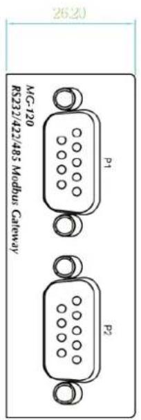
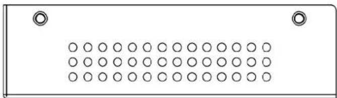


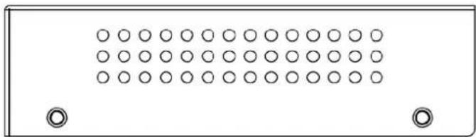
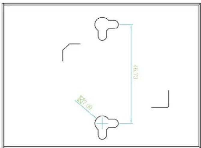
Unit: mm
2.1.3 Front / Top Panel
The front panels of the Modbus Gateways are shown in Figure 2-1-1.

Figure 2-1-1: Front Panels of Modbus Gateway
The top panel of the MG-120 is shown in Figure 2-1-2.
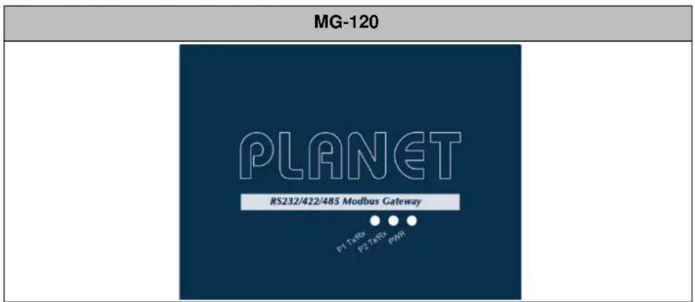
Figure 2-1-2: Top Panel of MG-120
■ Fast TP/ SFP interface
10/100BASE-TX copper, RJ45 twisted-pair: Up to 100 meters.
100BASE-FX SFP interface, Up to 2km\~120km, vary on SFP modules.
Serial Interface
Supports RS-232, RS-422, RS-485 2-wire and RS485 4-wire.
2.1.4 LED Indications
The front/top panel LEDs indicate the instant status of power and system status, port links and data activity; they help monitor and troubleshoot when needed.
■ System
| LED | Color | Function | |
| PWR | Green | Lights | Power is activated. |
| Serial (TX/RX) | Green Blinks | To indicate the Serial Port is receiving or sending data | |
■ 10/100BASE-TX/100BASE-FX Port
MG-110/115A
| TP or Fiber | Green | Lights | To indicate that the Fast Ethernet port is successfully connecting to the network at 10Mbps or 100Mbps (Fiber port only 100Mbps) |
| Blinks | To indicate the Fast Ethernet Port is receiving or sending data |
MG-120
| TP Port | Off | To indicate that the Fast Ethernet port is successfully connecting to the network at 10Mbps. | |
| Amber(100) | Lights | To indicate that the Fast Ethernet port is successfully connecting to the network at 100Mbps. | |
| Green(LNK/ACT) | Blinks | To indicate the TP Port is receiving or sending data |
2.1.5 Rear Panel
The rear panels of Modbus Gateways consist of one DC jack, which accepts input power with 5V DC, 2A (Figure 2-1-3).

Figure 2-1-3: One DC jack for DC power input
■ Reset button
On the rear panel, the reset button is designed for rebooting the system. The following is the summary table of the reset button functions:
| Reset Button | Reset Button Pressed and Released | Function |
| System Reset | < 5 sec: System reboot | Reboot the Modbus Gateway |
| > 5 sec: Factory default | Reset the Modbus Gateway to Factory Default configuration. The Modbus Gateway will then reboot and load the default settings as shown below:Default Username: adminDefault Password: adminDefault IP address: 192.168.0.100Subnet mask: 255.255.255.0Default Gateway: 192.168.0.254 |
2.1.6 Power Information:
The central pole of the Modbus Gateway's power jacks measures 2.5mm wide that require +5VDC power input. It conforms to the bundled AC-DC adapter and PLANET's media chassis. Should you have the issue of power connection, please contact your local sales representative.
Please keep the AC-DC adapter as a spare part when the Modbus Gateway is installed in a media chassis.(MG-110/115A)
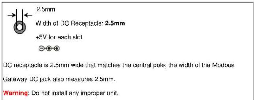
The device is a power-required device, meaning it will not work till it is powered. If your networks should be active all the time, please consider using UPS (Uninterrupted Power Supply) for your device. It will prevent you from network data loss or network downtime.
In some areas, installing a surge suppression device may also help to protect your Modbus Gateway from being damaged by unregulated surge or current to the converter or the power adapter.
2.1.7 Serial Port Pin Define
| Male DB9 | Pin | RS232 | RS422RS485-4W | RS485-2W |
 | 1 | DCD | TxD+ | -- |
| 2 | RxD | TxD- | -- | |
| 3 | TxD | RxD- | Data- | |
| 4 | DTR | RxD+ | Data+ | |
| 5 | GND | GND | GND | |
| 6 | DSR | -- | -- | |
| 7 | RTS | -- | -- | |
| 8 | CTS | -- | -- | |
| 9 | -- | -- | -- |
2.2 Installing the Modbus Gateway
This section describes how to install your Modbus Gateway and make connections to the Modbus Gateway. Please read the following section and perform the procedure in the order being presented. To install your Modbus Gateway on a desktop or rack, simply complete the following steps.
2.2.1 Installation Steps
- Unpack the Modbus Gateway
- Check if the DIN-rail bracket is screwed on the Modbus Gateway or not. If the DIN-rail bracket is not screwed on the Modbus Gateway, please refer to DIN-rail Mounting section for DIN-rail installation. If users want to wall-mount the Modbus Gateway, please refer to the Wall Mount Plate Mounting section for wall-mount plate installation.
- To hang the Modbus Gateway on the DIN-rail track or wall.
- Power on the Modbus Gateway. Connect the 5V DC power adapter to the Modbus Gateway, the power LED on the Modbus Gateway will light up. Please refer to the LED Indicators section for indication of LED lights.
- Prepare Network cables for Ethernet connection.
■ Use standard network (UTP) cables with RJ45
■ Use Multi-mode or Single-mode fiber patch cord with LC connector and 100BASE-FX SFP transceiver (MG-115A only).
- Insert one side of RJ45 cable (category 5) or Fiber cable into the Modbus Gateway Ethernet port (RJ45/SFP port) while the other side to the network device's Ethernet port (RJ45/SFP port), e.g., Switch PC or Server. The "LNK/ACT" LED on the Modbus Gateway will light up when the cable is connected with the network device. Please refer to the LED Indicators section for LED light indication.

Make sure that the connected network devices support MDI/MDI-X. If it does not support, use the crossover Category 5 cable.
- When all connections are set and all LED lights show normal, the installation is completed.
2.2.2 Wall-mount Installation
Step 1: Please find the wall that can mount the Modbus Gateway
Step 2: Screw two screws on the wall.

Step 3: Hang the Modbus Gateway on the screws from the wall.
Step 4: Refer to Chapter 2.1.5 Power Information on power supply to the Modbus Gateway.


Before mounting the device to the wall, please check the location of the electrical outlet and the length of the Ethernet cable.
2.2.3 Media Chassis Installation (MG-110/115A)
To install the Modbus Gateway in a 10-inch or 19-inch standard rack, follow the instructions described below.
Step 1: Place your Modbus Gateway on a hard flat surface, with the front panel positioned towards your front side.
Step 2: Carefully slide in the module until it is fully and firmly fitted into the slot of the chassis; the Power LED of the Modbus Gateway will turn ON.

Figure 3-2: Insert Modbus Gateway into an available slot

Caution
- Never push the Modbus Gateway into the slot with force; it could damage the chassis.
- The Media Converter Chassis supports hot-swap; there is no need to turn off the whole chassis before sliding in the new converter.
2.2.4 Optional DIN-rail Installation
There are two DIN-rail holes on the left side of the Modbus Gateway that allows to be easily installed by DIN-rail mounting. PLANET optional DIN-rail mounting kit – RKE-DIN -- can be ordered separately. Refer to the following steps for the DIN-rail mounting of the Modbus Gateway:
Step 1: Screw the DIN rail on the Modbus Gateway

Step 2: Now slide the DIN rail into the track.
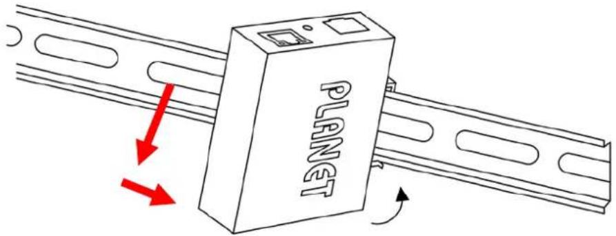
Step 3: Check whether the DIN rail is tightly on the track.


You must use the screws supplied with the mounting brackets. Damage caused to the parts by using incorrect screws would invalidate your warranty.
Caution
3. MODBUS GATEWAY MANAGEMENT
This chapter covers the following topics as to how to manage the Modbus Gateway:
- Requirements
■ Web Management
■ Remote Management
■ PLANET Smart Discovery Utility
■ MB VCOM Utility
3.1 Requirements
■ Workstations running Windows 2000/XP, 2003, Vista/7/8/10, 2008, Mac OS 9 or later, or Linux, UNIX, or other platforms compatible with TCP/IP protocols.
■ Workstation is installed with Ethernet NIC (Network Interface Card)
■ Network cables
• Use standard network (UTP) cables with RJ45
- Use Multi-mode or Single-mode fiber patch cord with LC connector and 100BASE-FX SFP transceiver (MG-115A only).
■ The above workstation is installed with Web Browser and JAVA runtime environment plug-in

It is recommended to use Internet Explorer 7.0 or above to access Modbus Gateway.
3.2 Web Management
The Modbus Gateway offers management features that allow users to manage the Modbus Gateway from anywhere on the network through a standard browser such as Microsoft Internet Explorer. After you set up your IP address for the switch, you can access the Modbus Gateway's Web interface applications directly in your Web browser by entering the IP address of the Modbus Gateway.
For example, the default IP address of the Modbus Gateway is 192.168.0.100, then the manager PC should be set to 192.168.0.x (where x is a number between 1 and 254, except 100), and the default subnet mask is 255.255.255.0.
![graph LR A["PC/Workstation with Web Browser\nIP Address:192.168.0.x"] -->|Ethernet\nRJ45 UTP Cable| B["MG Modbus Gateway\nIP Address:192.168.0.100"]](/content/2026/05/900935/images/ad3f3e507ecccfa8061fb695edc4d80f421c0e74f56a7e77a747c2388d6c4eee.jpg)
Figure 3-2-1: Web Management
You can then use your Web browser to list and manage the Modbus Gateway configuration parameters from one central location, just as if you were directly connected to the Modbus Gateway's console port. Web Management requires either Microsoft Internet Explorer 7.0 or later, Safari or Mozilla Firefox 1.5 or later.
3.2.1 Logging in to the Modbus Gateway
- Use Internet Explorer 8.0 or above for Web browser and enter IP address http://192.168.0.100 (the factory default IP address) to access the Web interface.
- When the following dialog box appears, please enter the default user name "admin" and password "admin" (or the password you have changed before) as shown in Figure 4-2.
Default IP Address: 192.168.0.100
Default User Name: admin
Default Password: admin

Figure 3-2-2: Login Screen
- After entering the password, the main screen appears as shown in Figure 3-2-3.

System Status
| Device Information | |||
| Model: | MG-110 | Firmware Version: | v1.1910b200518 |
| Server name: | Modbus Gateway | ||
| Current Time: | 2000-01-01 02:21 | System Up Time: | 0 days 2h:21m:57s |
| IPv4 Configuration | |||
| IP Configuration: | Static | ||
| IP Address: | 192.168.0.100 | Subnet Mask: | 255.255.255.0 |
| Gateway: | 192.168.0.254 | Primary DNS: | |
| Second DNS: | MAC Address: | 66:09:07:03:14:89 | |
Figure 3-2-3: Web Main Screen of Modbus Gateway
- The Main Menu in the middle of the Web page lets you access all the functions and statuses. It appears as shown in Figure 3-2-4.

Figure 3-2-4: Main menu
Now, you can use the Web management interface to continue the Modbus Gateway management. Please refer to the user manual for more.

- For security reason, please change and memorize the new password after this first setup.
- Only accept command in lowercase letter under web interface.
3.3 Remote Management
The Modbus Gateway also supports Telnet for remote management. You can use Telnet to open a terminal session over one of the Ethernet ports. The Modbus Gateway asks for user name and password for remote login when using Telnet; please use the following default IP address, username and password for the first-time login.
Default IP Address: 192.168.0.100
Default Username: admin
Default Password: admin
You will be presented with a text menu displaying the Modbus Gateway's general settings, which you will be able to view and modify. It appears as shown in Figure 3-3-1.
![UserName: admin Password: **** * Corporation : PLANET * Model : MG-110 * MAC Address : 66:09:07:03:14:89 * Firmware Version : v1.1910b200518 * Ethernet IP Address : 192.168.0.100 Main Menu [1] Basic [2] Accessible IP [3] Network [4] SNMP [5] Change password [6] Load factory default [s] Save and Rest…](/content/2026/05/900935/images/556997dc5146407b959b5ca528f2b0171b808ca0030bc0003530d4a31d003bf9.jpg)
Figure 3-3-1: Remote management
3.4 PLANET Smart Discovery Utility
For easily listing the Modbus Gateway in your Ethernet environment, the Planet Smart Discovery Utility is an ideal solution. The following installation instructions are to guide you to running the Planet Smart Discovery Utility.
- Download the Planet Smart Discovery Utility from the administrator PC.
- Run this utility as the following screen appears.
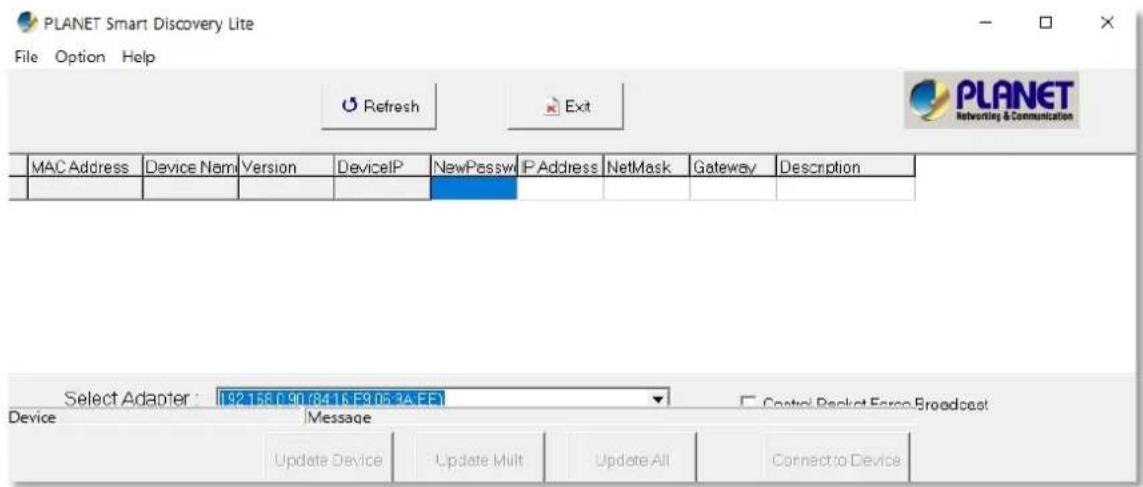
Figure 3-4-1: Planet Smart Discovery Utility Screen

If there are two LAN cards or above in the same administrator PC, choose a different LAN card by using the "Select Adapter" tool.
- Press the "Refresh" button for the currently connected devices in the discovery list as shown in Figure 3-4-2.:

Figure 3-4-2: Planet Smart Discovery Utility Screen
-
This utility shows all the necessary information from the devices, such as MAC address, device name, firmware version, and device IP subnet address. It can also assign new password, IP subnet address and description to the devices.
-
After setup is completed, press the "Update Device", "Update Multi" or "Update All" button to take effect. The functions of the 3 buttons above are shown below:
■ Update Device: Use current setting on one single device.
■ Update Multi: Use current setting on multi-devices.
Update All: Use current setting on whole devices in the list.
The same functions mentioned above also can be found in "Option" tools bar.
- To click the "Control Packet Force Broadcast" function, it allows you to assign a new setting value to the Web Smart Switch under a different IP subnet address.
- Press the "Connect to Device" button and the Web login screen appears as shown in Figure 3-4-2.
- Press the "Exit" button to shut down the Planet Smart Discovery Utility.
3.5 Getting Started with MB VCOM Utility
With MB VCOM Utility, you can easily search one or multiple MG-110 or MG-115A Modbus Gateway over the network from a remote location.
![graph LR A["PC"] -->|Ethernet| B["PLANET"] C["COM1 (Port1)"] -->|Ethernet| B D["MB VCOM"] --> A E["Serial Device"] --> F["Serial bus"]](/content/2026/05/900935/images/64fabb840540485fd3a70c235f423fc9fc08c64e94cf477427debf3eac487793.jpg)
3.5.1 Installation of MB VCOM Utility
The MG-110/MG-115A MB VCOM Utility can be downloaded from PLANET Web site. Please locate and run the setup program "mbgsetup.exe" and follow the on-screen instructions.

download link: https://www.planet.com.tw/en/support/downloads?&method=keyword&keyword=MG&view=6#list After installing, rebooting your workstation/PC is required.

If you have difficulty in downloading or executing MB VCOM Utility turn off the firewall and anti-virus software first.
3.5.2 Searching Modbus Gateway
First click "Add Device" and then click "Search" if Serial Server has access to network, as shown below.

This section introduces the configuration and functions of the Web-based management from Modbus Gateway.
About Web-based Management
The Modbus Gateway offers management features that allow users to manage the Modbus Gateway from anywhere on the network through a standard browser such as Microsoft Internet Explorer.
The Web-based Management supports Internet Explorer 7.0. It is based on Java Applets with an aim to reduce network bandwidth consumption, enhance access speed and present an easy viewing screen.

By default, IE7.0 or later version does not allow Java Applets to open sockets. The user has to explicitly modify the browser setting to enable Java Applets to use network ports.
The Modbus Gateway can be configured through an Ethernet connection, making sure the manager PC must be set to the same IP subnet address with the Modbus Gateway.
For example, the default IP address of the Modbus Gateway is 192.168.0.100, then the manager PC should be set to 192.168.0.x (where x is a number between 1 and 254, except 100), and the default subnet mask is 255.255.255.0.
If you have changed the default IP address of the Modbus Gateway to 192.168.1.1 with subnet mask 255.255.255.0 via console, then the manager PC should be set to 192.168.1.x (where x is a number between 2 and 254) to do the relative configuration on manager PC.
![graph LR A["PC/Workstation with Web Browser\nIP Address: 192.168.0.x"] -->|Ethernet\nRJ45 UTP Cable| B["MG Modbus Gateway\nIP Address: 192.168.0.100"]](/content/2026/05/900935/images/e8a11a5aae87ba9119a8aa1a398ddb7b7544d5c49cf60aa2ea52a7ab5e897c52.jpg)
Figure 4-1-1: Web Management
■ Logging on to the Modbus Gateway
- Use Internet Explorer 7.0 or above Web browser. Enter the factory default IP address to access the Web interface. The factory default IP address is shown as follows:
Default IP Address: 192.168.0.100
Default Username: admin
Default Password: admin
- When the following login screen appears, please enter the default username "admin" with password "admin" (or the username/password you have changed via console) to log in the main screen of Modbus Gateway. The login screen in Figure 4-1-2 appears.
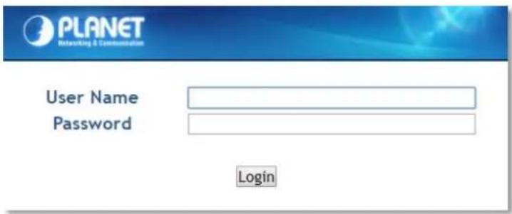
Figure 4-1-2: Login Screen
- After a successful login, the main screen appears as shown in Figure 4-1-3 below.

System Status
| Device Information | |||
| Model: | MG-110 | Firmware Version: | v1.1910b200518 |
| Server name: | Modbus Gateway | ||
| Current Time: | 2000-01-01 02:21 | System Up Time: | 0 days 2h:21m:57s |
| IPv4 Configuration | |||
| IP Configuration: | Static | ||
| IP Address: | 192.168.0.100 | Subnet Mask: | 255.255.255.0 |
| Gateway: | 192.168.0.254 | Primary DNS: | |
| Second DNS: | MAC Address: | 66:09:07:03:14:89 | |
Figure 4-1-3: Web Main Page
Now, you can use the Web management interface to continue the switch management or manage the Modbus Gateway by Web interface.
4.1 Main Web Page
The Modbus Gateway provides a Web-based browser interface for configuring and managing it. This interface allows you to access the Modbus Gateway using the Web browser of your choice. The main web page is shown in Figure 4-1-4

System Status
| Device Information | |||
| Model: | MG-110 | Firmware Version: | v1.1910b200518 |
| Server name: | Modbus Gateway | ||
| Current Time: | 2000-01-01 07:03 | System Up Time: | 0 days 7h:3m:39s |
| IPv4 Configuration | |||
| IP Configuration: | Static | ||
| IP Address: | 192.168.0.100 | Subnet Mask: | 255.255.255.0 |
| Gateway: | 192.168.0.254 | Primary DNS: | |
| Second DNS: | MAC Address: | 66:09:07:03:14:89 | |
Figure 4-1-4: Web Main Page
Main Menu
Via the Web Management, the administrator can set up the Modbus Gateway by selecting the functions that are listed in the Main Function. The screen in Figure 4-1-5 appears.

Figure 4-1-5: Modbus Gateway Main Functions Menu
| Object Description | |
| Basic | The essential device information of Modbus Gateway. |
| Accessible IP | To configure IP addresses lists to prevent unauthorized access. |
| Network | To configure IP address information of Modbus Gateway. |
| Modbus Gateway | To configure serial port value and port mode of Modbus Gateway. |
| SNMP | To configure SNMP information of Modbus Gateway. |
| Maintenance | The management of Modbus Gateway. |
| Save and Restart | Save the configuration and reboot device. |
| Refresh the page | |
| Log out the Modbus Gateway. |
4.2 System
Use the System menu items to display and configure basic administrative details of the Modbus Gateway. Under the System, the following topics are provided to configure and view the system information. This section has the following items:
■ System The Modbus Gateway system information is provided here.
■ Port This page displays status of each port.
■ Device Configure device name and syslog server on this page.
■ Time Configure NTP server or manually adjust time on this page.
■ Console Configure management methods on this page.
■ Email Set up the SMTP mail parameters for further operation of events.
4.2.1 System
The System page provides basic information for the current device. System page helps an administrator to identify software version, system uptime and IP address information. The screen in Figure 4-2-1 appears.
System Status
| Device Information | |||
| Model: | MG-110 | Firmware Version: | v1.1910b200518 |
| Server name: | Modbus Gateway | ||
| Current Time: | 2000-01-01 07:32 | System Up Time: | 0 days 7h:32m:6s |
| IPv4 Configuration | |||
| IP Configuration: | Static | ||
| IP Address: | 192.168.0.100 | Subnet Mask: | 255.255.255.0 |
| Gateway: | 192.168.0.254 | Primary DNS: | |
| Second DNS: | MAC Address: | 66:09:07:03:14:89 | |
Figure 4-2-1: System Status Page Screenshot
The page includes the following fields:
Device Information
| Object Description | |
| • Model | Specifies the device model name. |
| • Firmware Version | The firmware version of Modbus Gateway. |
| • Server Name | The system name configured in Basic/Device Name. |
| • Current Time | The current (GMT) system time and date. |
| • System Up Time | The period of time the device has been operational. |
IPv4 Configuration
| Object Description | |
| • IP Configuration | The status of IPv4 configuration. |
| • IP Address | The current IPv4 address of the device. |
| • Subnet Mask | The current IPv4 subnet mask of the device. |
| • Gateway | The current IPv4 gateway of the device. |
| • Primary DNS | The current first DNS server of the device. |
| • Second DNS | The current second DNS server of the device. |
| • MAC Address | Specifies the device MAC address. |
4.2.2 Port
This Port page displays the status of each port, including operation mode and serial settings. The screen in Figure 4-2-2 appears.
Port Status
| No. | Operation Mode | Baud Rate | Stop Bits | Data Bits | Parity | Interface | Flow Control |
| 1 | RTU Slave | 921600 | 1 | 8 | None | RS-232 | None |
Figure 4-2-2: Port Status Page Screenshot
The following column shows the Port statuses:
| Object Description | |
| • No. | The serial number (No.) indicates port number. It can be directly linked to the corresponding page settings. |
| • Operation Mode | The current operation mode of Modbus Gateway. |
| • Baud Rate | The rate of data transmission to and from the attached modbus serial device. |
| • Stop Bits | The stop bit follows the data and parity bits in serial communication. It indicates the end of transmission. The default is 1. |
| • Data Bits | Indicates the number of the bits in a transmitted data package. The default is 8. |
| • Parity | Checks for the parity type. The default value is none. |
| • Interface | The device server supports three interfaces. The default value is RS-232.■ RS-232■ RS-422■ RS-485 2-Wire■ RS-485 4-Wire |
| • Flow Control | The method is used to suspend and resume data transmission to ensure that data is not lost. The default value is none. |
4.2.3 Device
This page provides configuration of device name and syslog server. The screen in Figure 4-2-3 appears.
Device Setup
| Server Name: | Modbus Gateway |
| Syslog Server: | 192.168.0.50 |
Figure 4-2-3: Device Setup Page Screenshot
The page includes the following fields:
| Object Description | |
| • Server Name | To configure the name of server. The default value is Server. |
| • Syslog Server | To configure IP address of syslog server. |

When applying any configuration changes of Modbus Gateway, it's required to save changed configuration and reboot system. Therefore the new configuration will be applied after rebooting.
4.2.4 Time
This page provides configuration of NTP server and Time modification. The screen in Figure 4-2-4 appears.
Time Setup

Figure 4-2-4: Time Setup Page Screenshot
The page includes the following fields:
| Object Description | |
| • NTP Time Server | To configure NTP server for time synchronization. The default is time.stdtime.gov.tw. |
| • Time Zone | Lists various Time Zones worldwide. Select appropriate Time Zone from the drop-down menu and click Save to set. |
| • Current Time | To manually set the Year / Mouth / Day/ Hour / Minute / Second or get time from PC in this page. |
4.2.5 Console
This page is to configure management methods for web and remote console. The screen in Figure 4-2-5 appears.
Console Setup

Figure 4-2-5: Console Setup Page Screenshot
The page includes the following fields:
| Object Description | |
| Web Console | To enable or disable access to the web console. The default is Enable. |
| Remote Console | To enable or disable access to the remote console. The default is Enable. |
| Current Time | To check whether the reset button is working or not. The default is No. |
4.2.6 Email
The page shows SMTP configuration. The screen in Figure 4-2-6 appears. You may set up SMTP mail parameters for further operation. If users want to send the alarm message out that contains "Log-Fail Warring", it will need to configure parameters here.
Email Setup

Figure 4-2-6: SMTP Setup Page Screenshot
The page includes the following fields:
| Object Description | |
| Enable Mail Alert | To Enable SMTP function. The default value is “Disable”. |
| SMTP Server | Set port number of SMTP service. The default number is “25”. |
| SMTP Server Port | Type the SMTP server name or the IP address of the SMTP server address. |
| SMTP Login Information | Username: Enter your login name for the SMTP Server.Password: Enter your password for the SMTP Server. |
| From | Enter the sender's e-mail address. This address is used for replying e-mails. |
| To | Enter the receiver's e-mail address. |
Alert Events:
| Object Description | |
| Cold Start Alert | To Enable the Cold Start Alert. The default value is “Disable”.Message: Enter the message of the e-mail. The default subject is “Cold Start Alert”. |
| Warm Start Alert | To Enable the Warm Start Alert. The default value is “Disable”.Message: Enter the message of the e-mail. The default subject is “Warm Start Alert”. |
| WEB Login Failure Alert | To Enable the WEB Login Failure Alert. The default value is “Disable”.Message: Enter the message of the e-mail. The default subject is “WEB Login Failure Alert”. |
4.3 Accessible IP
This page provides the specified IP address to connect with Modbus Gateway. When the list of accessible IP is enabled, only IP address in the list can connect to device. When the function is disabled, there is no such restriction. The list allows user to configure up to four IP groups. The accessible IP setup screen in Figure 4-3-1 appears.
Accessible IP Setup

Figure 4-3-1: Accessible IP Setup Page Screenshot
The page includes the following fields:
| Object Description | |
| Active | Configure the accessible IP list. Possible modes are:Disabled: Disable accessible IP lists.Enabled: Enable accessible IP lists. |
| Activate NO | Enable or disable activated IP groups. |
| Start IP Address | Enter the IP address for starting. |
| End IP Address N | Enter the IP address for ending |
Example
| Allowed hosts | Start: IP Address setting | End: IP Address N |
| • Any host | disable disable | |
| • 192.168.0.120 | 192.168.0.120 | |
| • 192.168.0.1 to 192.168.0.254 | 192.168.0.1 | 192.168.0.254 |
4.4 Network
This page allows the user to configure IPv4 or IPv6 address. The IP configuration screen in Figure 4-4-1 appears.
IP Configuration
| IPv4 Configuration | |
| IP Configuration: | Static ▼ |
| IP Address: | 192.168.0.100 |
| Subnet Mask: | 255.255.255.0 |
| Gateway: | 192.168.0.254 |
| Primary DNS: | |
| Second DNS: | |
Figure 4-4-1: IP Configuration Page Screenshot
The page includes the following fields:
IPv4
| Object Description | |
| • IP Configuration | Configure static or DHCP to get IPv4 address. The default value is static.■ static: Set a fixed IPv4 address that was manually configured for a device■ DHCP: Set IPv4 address automatically assigned from a DHCP server. |
| • IP Address | The current IPv4 Address of the device. The IP Address could be manually assigned. The default value is 192.168.0.100. |
| • Subnet Mask | The current IP subnet mask of the device. The default value is 255.255.255.0. |
| • Gateway | The default gateway for the IP interface. The default value is 192.168.0.254. |
| • Primary DNS | Configure the first DNS server. |
| • Second DNS | Configure the second DNS server. |
4.5 Modbus Gateway
The following figure shows port settings. Note that these settings need to match the parameters on serial port of the Modbus device. Each parameter is described in details in the following section. The port configuration screen in Figure 4-5-1 appears.
Port 1 Setup

Figure 4-5-1: Port Setup Page Screenshot
4.5.1 Serial setup
The serial setup screen is shown in Figure 4-5-2.

Figure 4-5-2: Serial Setup Page Screenshot
| Object Description | |
| Operation Mode | Used to set Modbus/serial on serial port. The Default is RTU Slave.■ Disable■ RTU Slave,■ RTU Master,■ ASCII Slave■ ASCII Master |
| Baud Rate | The rate of data transmission to and from the attached serial device. It allows 50 bps to 921600 bps. The default is 921600 bps. |
| Stop Bits | The stop bit follows the data and parity bits in serial communication. It indicates the end of transmission. The default is 1. |
| Data Bits | Indicates the number of the bits in a transmitted data package. The allowed value is 5,6,7,8 and default value is 8. |
| Parity | This parameter controls the error checking mode. It support five modes and default value is none.■ Even■ Odd■ None■ Space■ Mark |
| • Interface | The device server supports three interfaces. The default value is RS-232.■ RS-232■ RS-422■ RS-485 2-Wire■ RS-485 4-Wire |
| • Flow Control | The method is used to suspend and resume data transmission to ensure that data is not lost. It supports four methods and default value isnone.■ None■ RTS/CTS■ Xon/Xoff■ DTR/DSR |
| • RTS ON delay | This parameter controls RTS turn on before data transmission. |
| • RTS OFF delay | This parameter controls RTS turn off after the transmission completes. |
| • Response Timeout | This parameter is used to configure how long the gateway will wait for a response from a Modbus ASCII or RTU slave. |
4.5.2 Operation mode
The Modbus Gateway makes connected Serial equipment become IP-based. That also makes them able to connect to a TCP/IP networking immediately. The Modbus Gateway allows traditional Computer/Client COM ports access to a serial equipment anywhere on the Ethernet LAN network.
This operation mode can be set up as Disable, RTU Slave/Master and ASCII Slave/Master. The operation mode screen in Figure 4-5-3 appears.
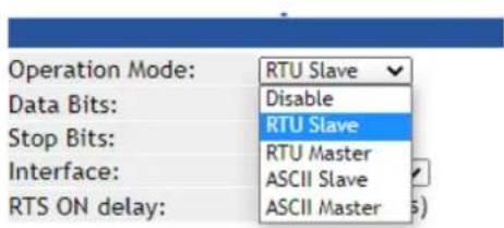
Figure 4-5-3: Operation Mode Screenshot
4.5.2.1 Disable mode
When selecting disabled operation mode, the device port can be disabled. The disable mode screen in Figure 4-5-4 appears.


Figure 4-5-4: Disable Mode Screenshot
Buttons
Apply
: Click to apply port config changes.

When applying any configuration changes of Modbus Gateway, it's required to save changed configuration and reboot system. Therefore the new configuration will be applied after rebooting.
4.5.2.2 RTU Slave mode
This function allows the users to use Modbus TCP master device and Modbus RTU device to achieve communication. The operation mode of the Industrial Modbus Gateway is set to RTU Slave. The remote pair master/slave topology in Figure 4-5-5 appears.
RTU Slave mode
![graph LR A["Modbus TCP Master"] -->|Ethernet| B["Modbus TCP"] B --> C["Modbus RTU Serial bus"] C --> D["RTU Slave"]](/content/2026/05/900935/images/b7b0818cfd0807e63512685ee139de81ece439712d286d1ef1273e906e2fabad.jpg)
Figure 4-5-5: RTU Slave Topology
The remote pair master mode screenshot in Figure 4-5-6 appears.

Figure 4-5-6: RTU Slave Mode Screenshot
4.5.2.3 RTU Master mode
This function allows the users to use Modbus RTU master device and Modbus TCP device to achieve communication. The operation mode of the Industrial Modbus Gateway is set to RTU Master. The serial telnet mode topology in Figure 4-5-7 appears.
RTU Master mode
![graph LR A["Modbus TCP Slave Device"] -->|Ethernet| B["Modbus TCP"] B --> C["Ethernet"] C --> D["PLANET"] D --> E["Modbus RTU Serial bus"] E --> F["RTU Master (HMI)"]](/content/2026/05/900935/images/f4f9cd68537119dddae2476186fed13414b0ad481fb34c87e5ff18aea3160755.jpg)
Figure 4-5-7: RTU Master Mode Topology
The serial Telnet mode screenshot in Figure 4-5-8 appears.



Figure 4-5-8: RTU Master Mode Screenshot
4.5.2.4 ASCII Slave mode
This function allows the users to use Modbus TCP master device and Modbus ASCII device to achieve communication. The operation mode of the gateway is set to ASCII Slave. The TCP server mode topology in Figure 4-5-9 appears.
ASCII Slave mode
![graph LR A["Modbus TCP Master"] -->|Ethernet| B["PLEHGT"] B --> C["Modbus ASCII Serial bus"] C --> D["ASCII Slave"]](/content/2026/05/900935/images/ecab8221430f2d1ae35f8a3ad2c50db2bc3354d4b26f09e33fa8eb7a225f7c33.jpg)
Figure 4-5-9: ASCII Slave Mode Topology
The TCP server mode screenshot in Figure 4-5-10 appears.
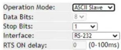


Figure 4-5-10: ASCII Slave Mode Screenshot
4.5.2.5 ASCII Master mode
This function allows the users to use Modbus ASCII master device and Modbus TCP device to achieve communication. The operation mode of the Industrial Modbus Gateway is set to ASCII Master. The TCP client mode topology in Figure 4-5-11 appears.
ASCII Master mode
![graph LR A["Modbus TCP Slave Device"] -->|Ethernet| B["Modbus TCP"] B --> C["ASCII"] C -->|Serial bus| D["Modbus ASCII"] D --> E["ASCII Master (HMI)"]](/content/2026/05/900935/images/68253869e7c60a1501d041bfea83074c5ccfaaf76e12dcfc4ba09d1c2eeb68ca.jpg)
Figure 4-5-11: ASCII Master Mode Topology
The TCP client mode screenshot in Figure 4-5-12 appears.
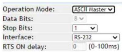


Figure 4-5-12: ASCII Master Mode Screenshot
4.5.3 MB COM
This page is to create virtual COM port for Modbus gateway. The default is disable.
MB COM Setup

4.5.4 Modbus Config
4.5.4.1 Router
The Modbus Gateway support four Modbus masters in each serial port which can communicate with the Modbus slave devices. It can be connected to a serial port by IP address or TCP port. The screen in Figure 4-5-14 appears.
Router Setup
| Index | Local Interface | Local IP / TCP port | Destination | |
| 1 | ||||
| 2 | ||||
| 3 | ||||
| 4 | ||||
| Apply | ||||
| Local Interface: | IP Address✓ | |||
| Local IP Address: | ||||
| Destination: | Select✓ | |||
| Add | Edit | Delete | ||
Figure 4-5-14: Router Status Page Screenshot
For example, IP address 192.168.0.60 is set and assigned to serial port 1. As shown below, it will forward directly to serial port 1 when you get a Modbus request that is sent to 192.168.0.60. The Router Setup screen in Figure 4-5-15 appears.

Router Setup
| Index | Local Interface | Local IP / TCP port | Destination | |
| Og | 1 | IP Address | 192.168.0.60 | Port 1 |
| Og | 2 | |||
| Og | 3 | |||
| Og | 4 |
Figure 4-5-15: Router Setup Page Screenshot
The page includes the following fields:
| Object Description | |
| Operation Mode | Used to set Modbus/serial on serial port. The Default is RTU Slave.■ Disable■ RTU Slave,■ RTU Master,■ ASCII Slave■ ASCII Master |
| Baud Rate | The rate of data transmission to and from the attached serial device. It allows 50 bps to 921600 bps. The default is 921600 bps. |
| Stop Bits | The stop bit follows the data and parity bits in serial communication. It indicates the endof transmission. The default is 1. |
| • Data Bits | Indicates the number of the bits in a transmitted data package. The allowed value is 5,6,7,8 and default value is 8. |
4.5.4.2 Mapping
The ID Mapping Setup is a routing mechanism for gateway. It can follow routing rule on this table to transfer Modbus request to the specific serial port or TCP server that connects the Modbus slave device. The screen in Figure 4-5-16 appears.
ID Mapping Setup
Figure 4-5-16: Mapping Status Page Screenshot
In block 1, it's a setting value for slave ID 1\~3 that will forward to serial port 1. When you get a Modbus requests with slave ID 1\~3, it will follow this rule to be routed to the targeted Modbus slave device. In block 2, you can select the one to add, edit or delete the rule on the table. The block 1 and block 2 screen in Figure 4-5-17 appears.
ID Mapping Setup
| Auto Device Routing | Disable▼ | Page 1~20▼ | |||
| Index | Router | Type | Slave ID Mapping (Virtual<=>Real) | Destination | |
| ○ | 1 | Manual | Serial | 1-3<=>1-3 | Port 1 |
| ○ | 2 | ||||
| ○ | 3 | ||||
| ○ | 4 | ||||
Figure 4-5-17: The Block 1 / Block 2 Screenshot
Basic setting
A Modbus device with slave ID 1 can be set to be connected to serial port 1 as shown in Figure 4-5-18

ID Mapping Setup
| Auto Device Routing Enable Page 1~20 | |||||
| Index | Router | Type | Slave ID Mapping (Virtual<=>Real) | Destination | |
| Og | 1 | Manual | Serial | 1-1<=1-1 | Serial 1 |
| Og | 2 | ||||
Figure 4-5-18: Basic setting of Mapping Screenshot
Auto Device Routing
It's a mechanism that will help you find where It is and get routed correctly on serial port. So users don't need to set the rule manually. If the Auto Device Routing is enabled, it will clear Slave ID Mapping value of the rule with serial port automatically.
ID Mapping Setup
| Auto Device Routing | Enable | ✓ | Page 1 ~ 20 | ||
| Index | Router | Type | Slave ID Mapping (Virtual<=>Real) | Destination | |
| 1 | Manual | Serial | 0-0<=>0-0 | Serial 1 | |
| 2 | |||||
| .8 | |||||
When you get a request with slave ID didn't exist on rule table. It will detect all serial port to find the target device and add on the rule table directly.
ID Mapping Setup
| Auto Device Routing Enable Page 1~20 | |||||
| Index | Router | Type | Slave ID Mapping (Virtual<=>Real) | Destination | |
| ○ | 1 | Manual | Serial | 0-0<=>0-0 | Serial 1 |
| ○ | 2 | Auto | Serial | 1-1<=>1-1 | Serial 2 |
| ○ | 3 | ||||
If there are two target devices with the same ID in two serial ports, it will show conflict. Check environment please.
ID Mapping Setup
| Auto Device Routing | Enable | ✓ | Page 1 ~ 20 | ||
| Index | Router | Type | Slave ID Mapping (Virtual<=>Real) | Destination | |
| ○ | 1 | Manual | Serial | 0-0<=>0-0 | Serial 1 |
| ○ | 2 | Auto | Serial | 2-2<=>2-2 | Serial 1 |
| ○ | 3 | Auto | Serial | 2-2<=>2-2 | Serial 2, Conflict |
| ○ | 4 | ||||
4.5.4.3 Parameters
This function allows setting the value for serial port COM configuration. Press the "Apply" button to set the value and the screen in Figure 4-5-19 appears
Parameters Setup

Figure 4-5-19: Parameters Setup Page Screenshot
The page includes the following fields:
| Object Description | |
| • Initial Delay | You can make the IP218 wait for some Modbus slave devices may take more time to boot up. It will force the IP218 to wait the initial delay setting before booting completes. |
| • Listen Port | This parameter (default:502) means the TCP port t communicates with the connected device. |
| • TCP Exception | If this setting is enabled, IP218 will return an exception in response when there is no response from the slave. If it's disabled, it will do nothing when there is no response. |
| • TCP Timeout | This parameter (default:1000) is used to configure how long IP218 will wait for a response from a Modbus TCP slave. If there is no response from the slave, the master will ignore and continue next step. This makes the Modbus system work improperly even if a Modbus slave device is faulty. |
4.5.5 Priority Control
It's a mechanism that Modbus Messaging Priority Control can make a certain requests for more immediate response times. It will be arranged to the front of queue to be sent when Modbus gateway detects a priority request
4.5.5.1 Master
The priority rule can be assigned by master (serial port or IP address). As above, it means the request from serial port 1 or 192.168.0.123 will be considered a priority request. The screen in Figure 4-5-20 appears
Master Control
| Specified Maters: Enable ▼ | |||
| Index | Type | Definition | |
| ○ | 1 | Serial Port | Serial 1 |
| ○ | 2 | IP Address | 192.168.0.123 |
| Apply | |||
| Type: TCP Address ▼ | |||
| IP Address: | |||
| Add Edit Delete | |||
Figure 4-5-20: Master Setup Page Screenshot
4.5.5.2 TCP
It is the same as priority master shown above, it means the request from port 1024 will be high priority. The screen in Figure 4-5-21 appears.
TCP Control

Figure 4-5-21: TCP Setup Page Screenshot
4.5.5.3 Request
The command type can also be made a priority request. Like the above, as requested by slave ID 3, function code 3 and data 00 00 00 03 will be high priority. The screen in Figure 4-5-22 appears.
Request Control

Figure 4-5-22: Request Setup Page Screenshot
4.6 SNMP Setup
Use the Port Menu to display or configure the Modbus Gateway's ports. This section includes the page that displays current port configurations. Ports can also be configured here. The Port Configuration screen in Figure 4-6-1 appears.
SNMP Setup

Figure 4-6-1: SNMP Setup page Screenshot
The page includes the following fields:
| Object Description | |
| • SNMP Active | Indicates the SNMP mode operation. Possible modes are:■ Disable: Disable SNMP mode operation.■ Enable: Enable SNMP mode operation. |
| • Community | Indicates the security name to map the community to the SNMP Groups configuration. |
| • Contact | The textual identification of the contact person for this managed node, together with information on how to contact this person. |
| • Location | The physical location of this node (e.g., telephone closet, 3rd floor). |
| • Trap Server | Indicates the SNMP trap destination address. It allows a valid IP address or domain name. |
Events
| Object Description | |
| Cold Start Trap | This event is triggered when the power is interrupted and restarted. |
| Warm Start Trap | This event occurs when the device is reset but does not turn off the power. |
| Authentication Failure Trap | This event occurs when an incorrect or unauthorized password are entered. |
4.7 Maintenance
Use the Port Menu to display or configure the Modbus Gateway's ports. This section includes the page that displays current port configurations. Ports can also be configured here.
4.7.1 Change Password
After logging in to the Modbus Gateway, user can make changes from the "Change Password" page. The Change Password screen in Figure 4-7-1 appears.
Change Password

Figure 4-7-1: Change Password Page Screenshot
The page includes the following fields:
| Object Description | |
| • New Password | A new password. It allows strings like A-Z, a-z, _,0-9 |
| • Confirm Password | Please enter the user's new password here again to confirm. |
4.7.2 Load Default
A user can reset the configuration of the Modbus Gateway on this page. The new configuration will applied after restarting system. The Load Default screen in Figure 4-7-2 appears.
Reset to Default

Figure 4-7-2: Reset to Default Page Screenshot
Buttons

: Click to reset to default.
Users can also export or import configuration settings of the Modbus Gateway on this page. The old configuration will be applied after import the config. The Export or Import Setting screen in Figure 4-7-3 appears.

Figure 4-7-3: Export or Import Setting Page Screenshot
4.7.3 Firmware Update
This page facilitates an update of the firmware controlling the switch. The Firmware Update screen in Figure 4-7-4 appears.
Firmware Update
Select A Local File Choose File No file chosen
Upgrade
Figure 4-7-4: Firmware Update Page Screenshot
To open Firmware Update screen, perform the following:
- Click Maintenance -> Firmware Update.
- The Firmware Update screen is displayed as in Figure 4-7-4.
- Click the “Choose File” button of the Main page; the file selection menu pops up for you to choose firmware.
- Select on the firmware and then click "Upgrade"; the Software Upload Progress would show the file with upload status.
- Once the software is loaded to the system successfully, the following screen Figure 4-7-5 appears. The system will load the new software after rebooting.
Information Note
Please wait while .... System will reboot automatically after finished.
100 % , Rebooting ... 94 seconds
Figure 4-7-5: Rebooting Screenshot
4.8 Save and Restart
When applying any configuration changes of Modbus Gateway, it's required to save changed configuration and reboot system.
Therefore the new configuration will be applied after rebooting. The Save and Restart screen in Figure 4-8-1 appears.
Save and Restart
The configuration has been changed.
Warning!! The system will automatically log out and reboot.
Apply
Figure 4-8-1 : Save and Restart Page Screenshot
Buttons
Apply
: Click to save changes and restart system.
5. SOFTWARE MB VCOM UTILITY
The "MB VCOM" Administration Suite provides you search function to find your MG-11x Modbus Gateway from a remote location. With MB VCOM Utility, you can easily install and search your MG-11x Modbus Gateway over the network. You can also run MB VCOM Utility from one location to manage multiple device servers. The setup program will be named mbgsetup.exe.
5.1 Installing the VCOM Utility
- When you run MB VCOM installer, a welcome window will appear as shown in Figure 5-1-1. Click Next to continue.

Figure 5-1-1 : Installing the VCOM Utility
- Click Next to accept suggested installation path, or click browse to select a different location as shown in Figure 5-1-2.

Figure 5-1-2 : Installing location
- The setup wizard will show the progress of the installation and status as shown in Figure 5-1-3.

Figure 5-1-3 : Installing Process
- Click Finish to successfully complete installation of VCOM software.as shown in Figure 5-1-4.

Figure 5-1-4 : Installation Finished
- Restart computer as shown in Figure 5-1-5.

Figure 5-1-5 : Restart System
5.2 Search Devices
- First click "Add Device" and then click "Search" if device has access to network, as shown in Figure 5-2-1.
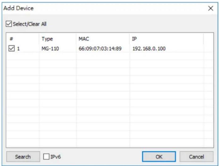
Figure 5-2-1 : Searching Devices
- After adding an MG-110 device as shown in Figure Figure 5-2-2.
When you close searching window, it will add device automatically on main window. If you want to modify MG-110, please click "Open in Browser" to modify on web page.

Figure 5-2-2: A device successfully added
This function should be set as VCOM mode on the Modbus Gateway. VCOM software will create the corresponding virtual COM ports for com port mapping as shown in Figure 5-3-1.

Figure 5-3-1 : VCOM software
Add Virtual COM port
- Click "Search" to search the network for device servers.
- Once a server has been found, select it to add it to the COM mapping list and Click "OK" to take effect as shown in Figure 5-3-2.
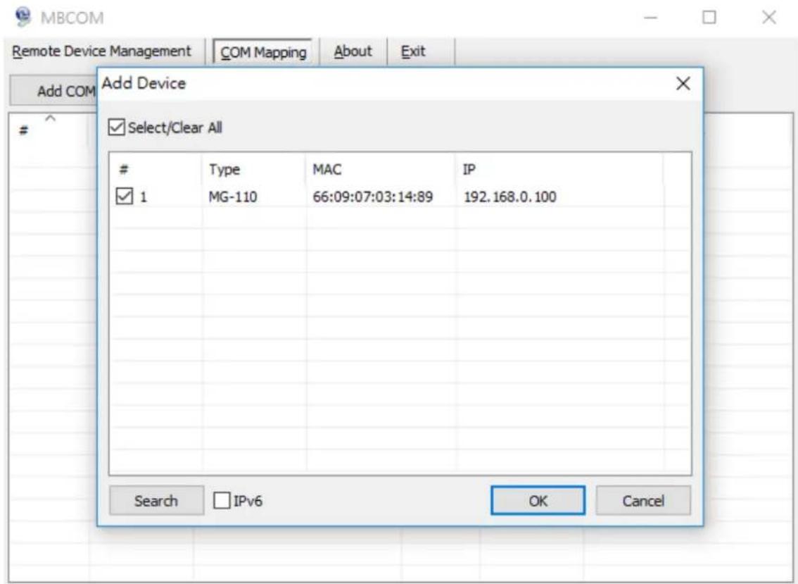
Figure 5-3-2 : VCOM software
- Virtual com ports are generated as shown in Figure 5-3-3.

Figure 5-3-3 : Virtual COM Ports
- From the Windows Device Manager, four COM Ports are added to the device list as shown in Figure 5-3-4.

Device Manager
File
Action
View
Help


Figure 5-3-4 : Virtual COM Ports


- USER'S MANUAL
- RS232/RS422/RS485
- MODBUS GATEWAY SERIES
- TRADEMARKS
- DISCLAIMER
- FCC WARNING
- CE MARK WARNING
- ENERGY SAVING NOTE OF THE DEVICE
- WEEE WARNING
- REVISION
- TABLE OF CONTENTS
- INTRODUCTION .... 5
- INSTALLATION .... 15
- MODBUS GATEWAY MANAGEMENT....27
- WEB CONFIGURATION....35
- SOFTWARE MB VCOM UTILITY 60
- INTRODUCTION
- 1.1 PACKET CONTENTS
- 1.2 PRODUCT DESCRIPTION
- STANDARD MODBUS TCP/RTU/ASCII NETWORK INTEGRATION
- A CONVERSION BRIDGE FOR FLEXIBLE NETWORK DEPLOYMENT
- DIFFERENCES BETWEEN SERIAL DEVICES AND MODBUS GATEWAY
- REMOTE MANAGEMENT
- MODBUS SERIAL PORT STATE MONITORING
- FIBER-OPTIC LINK CAPABILITY EXTENDS THE RANGE OF NETWORK DEPLOYMENT (ONLY MG-115A)
- EASY CHASSIS INSTALLATION (ONLY MG-110/115A)
- OPTIONAL INSTALLATION METHOD
- 1.3 HOW TO USE THIS MANUAL
- 1.4 PRODUCT FEATURES
- SERIAL INTERFACE
- ETHERNET INTERFACE
- MANAGEMENT FUNCTION
- CASE AND INSTALLATION
- 1.5 PRODUCT SPECIFICATIONS
- INSTALLATION
- 2.1 HARDWARE DESCRIPTION
- 2.1.1 PHYSICAL DIMENSIONS
- 2.1.3 FRONT / TOP PANEL
- FAST TP/ SFP INTERFACE
- 2.1.4 LED INDICATIONS
- 2.1.5 REAR PANEL
- RESET BUTTON
- 2.1.6 POWER INFORMATION
- 2.1.7 SERIAL PORT PIN DEFINE
- 2.2 INSTALLING THE MODBUS GATEWAY
- 2.2.1 INSTALLATION STEPS
- 2.2.2 WALL-MOUNT INSTALLATION
- 2.2.3 MEDIA CHASSIS INSTALLATION (MG-110/115A)
- 2.2.4 OPTIONAL DIN-RAIL INSTALLATION
- MODBUS GATEWAY MANAGEMENT
- 3.1 REQUIREMENTS
- 3.2 WEB MANAGEMENT
- 3.2.1 LOGGING IN TO THE MODBUS GATEWAY
- 3.3 REMOTE MANAGEMENT
- 3.4 PLANET SMART DISCOVERY UTILITY
- 3.5 GETTING STARTED WITH MB VCOM UTILITY
- 3.5.1 INSTALLATION OF MB VCOM UTILITY
- 3.5.2 SEARCHING MODBUS GATEWAY
- TYPE MAC IP DEVICE DESCRIPTION
- ABOUT WEB-BASED MANAGEMENT
- LOGGING ON TO THE MODBUS GATEWAY
- 4.1 MAIN WEB PAGE
- MAIN MENU
- 4.2 SYSTEM
- 4.2.1 SYSTEM
- 4.2.2 PORT
- 4.2.3 DEVICE
- 4.2.4 TIME
- 4.2.5 CONSOLE
- 4.2.6 EMAIL
- 4.3 ACCESSIBLE IP
- 4.4 NETWORK
- 4.5 MODBUS GATEWAY
- 4.5.1 SERIAL SETUP
- 4.5.2 OPERATION MODE
- 4.5.2.1 DISABLE MODE
- BUTTONS
- 4.5.2.2 RTU SLAVE MODE
- 4.5.2.3 RTU MASTER MODE
- 4.5.2.4 ASCII SLAVE MODE
- 4.5.2.5 ASCII MASTER MODE
- 4.5.3 MB COM
- 4.5.4 MODBUS CONFIG
- 4.5.4.1 ROUTER
- 4.5.4.2 MAPPING
- BASIC SETTING
- ID MAPPING SETUP
- AUTO DEVICE ROUTING
- 4.5.4.3 PARAMETERS
- PARAMETERS SETUP
- 4.5.5 PRIORITY CONTROL
- 4.5.5.1 MASTER
- MASTER CONTROL
- 4.5.5.2 TCP
- TCP CONTROL
- 4.5.5.3 REQUEST
- REQUEST CONTROL
- 4.6 SNMP SETUP
- 4.7 MAINTENANCE
- 4.7.1 CHANGE PASSWORD
- 4.7.2 LOAD DEFAULT
- 4.7.3 FIRMWARE UPDATE
- FIRMWARE UPDATE
- INFORMATION NOTE
- 4.8 SAVE AND RESTART
- SAVE AND RESTART
- SOFTWARE MB VCOM UTILITY
- 5.1 INSTALLING THE VCOM UTILITY
- 5.2 SEARCH DEVICES
- TYPE IP PORT COM PORT CONNECTION STATUS
- ADD VIRTUAL COM PORT
Brand : Planet
Model : MG-110
Category : Network gateway