
AMP22 - Receiver Audac - Free user manual and instructions
Find the device manual for free AMP22 Audac in PDF.


| Product Type | Receiver |
| Brand | Audac |
| Model | AMP22 |
| Dimensions (W x D x H) | 430 x 300 x 100 mm |
| Weight | 5 kg |
| Power Supply | 230 V AC, 50 Hz |
| Power Consumption | 100 W |
| Output Power | 2 x 100 W RMS (8 ohms) |
| Frequency Response | 20 Hz - 20 kHz |
| Signal-to-Noise Ratio | > 90 dB |
| Total Harmonic Distortion | < 0.05% |
| Input Sensitivity | 200 mV |
| Speaker Impedance | 4 - 16 ohms |
| Audio Inputs | 3 x RCA, 1 x Optical, 1 x Coaxial |
| Audio Outputs | 2 x Speaker, 1 x Pre-out |
| Tuner | FM/AM |
| Additional Features | Bluetooth, USB Playback, Remote Control |
| Cleaning Instructions | Wipe with a dry, soft cloth. Do not use liquids. |
| Safety Precautions | Avoid moisture. Unplug during thunderstorms. |
| Spare Parts & Repairability | Contact Audac support. Repairs by qualified technician only. |
Frequently Asked Questions - AMP22 Audac
User questions about AMP22 Audac
0 question about this device. Answer the ones you know or ask your own.
Ask a new question about this device
Download the instructions for your Receiver in PDF format for free! Find your manual AMP22 - Audac and take your electronic device back in hand. On this page are published all the documents necessary for the use of your device. AMP22 by Audac.
USER MANUAL AMP22 Audac
natural_image
Line drawing of an audio jack unit (no text or symbols on the device body)ADDITIONAL INFORMATION
This manual is put together with much care, and is as complete as could be on the publication date. However, updates on the specifications, functionality or software may have occurred since publication. To obtain the latest version of both manual and software, please visit the Audac website @ www.audac.eu.

Introduction 05
Mini stereo power amplifier 05
Precautions 06
Chapter 1 08
Connections and connectors 08
Chapter 2 010
Overview AMP22 010
Chapter 3 012
AMP22 Quick start guide 012
Connecting the AMP22 012
Configuring the AMP22 013
Ready 013
Technical specifications 014
Mini stereo power amplifier
The AMP22 is a mini stereo power amplifier with a power rating of 2 x 15 Watt, which lends itself perfectly to small speaker systems requiring compact and economical audio solutions. It offers the ideal solution for applications such as classrooms, offices and meeting rooms where a small amount of speakers are required.
The compact size and very high efficiency makes it perfectly suited to be hidden in a closet, on a false ceiling or mounted under a desk or table.
The combination of the stereo balanced line and microphone input make it perfectly suited for applications where it should be used in combination with projection screens and video sources while a microphone is connected. Two gain potentiometers make it possible to control the sensitivity and balance between music and speech, while a switch allows bridging of the output channels to obtain one channel with merged output power.
A remote wall panel can be connected for applications where local mixing of the inputs is desirable, while large distances can be covered between the source and amplifier using simple CAT5E twisted pair cabling. The volume controller input allows connection of an additional wall controller for overall volume control.
The Class-D Amplifier technology, standby mode and included switching power supply makes this device compliant to Energy Star 3.0 and other strict energy efficiency and environmental requirements.

READ FOLLOWING INSTRUCTIONS FOR YOUR OWN SAFETY
ALWAYS KEEP THESE INSTRUCTIONS. NEVER THROW THEM AWAY
ALWAYS HANDLE THIS UNIT WITH CARE
HEED ALL WARNINGS
FOLLOW ALL INSTRUCTIONS
NEVER EXPOSE THIS EQUIPMENT TO RAIN, MOISTURE, ANY DRIPPING OR SPLASHING LIQUID, AND NEVER PLACE AN OBJECT FILLED WITH LIQUID ON TOP OF THIS DEVICE
NO NAKED FLAME SOURCES, SUCH AS LIGHTED CANDLES, SHOULD BE PLACED ON THE APPARATUS
DO NOT PLACE THIS UNIT IN AN ENCLOSED ENVIRONMENT SUCH AS A BOOKSHELF OR CLOSET. ENSURE THERE IS ADEQUATE VENTILATION TO COOL THE UNIT. DO NOT BLOCK THE VENTILATION OPENINGS.
DO NOT STICK ANY OBJECTS THROUGH THE VENTILATION OPENINGS.
DO NOT INSTALL THIS UNIT NEAR ANY HEAT SOURCES SUCH AS RADIATORS OR OTHER APPARATUS THAT PRODUCE HEAT
DO NOT PLACE THIS UNIT IN ENVIRONMENTS WHICH CONTAIN HIGH LEVELS OF DUST, HEAT, MOISTURE OR VIBRATION
THIS UNIT IS DEVELOPED FOR INDOOR USE ONLY. DO NOT USE IT OUTDOORS
PLACE THE UNIT ON A STABLE BASE OR MOUNT IT IN A STABLE RACK
ONLY USE ATTACHMENTS & ACCESSORIES SPECIFIED BY THE MANUFACTURER
UNPLUG THIS APPARATUS DURING LIGHTNING STORMS OR WHEN UNUSED FOR LONG PERIODS OF TIME
ONLY CONNECT THIS UNIT TO A MAINS SOCKET OUTLET WITH PROTECTIVE EARTHING CONNECTION
THE MAINS PLUG OR APPLIANCE COUPLER IS USED AS THE DISCONNECT DEVICE, SO THE DISCONNECT DEVICE SHALL BE READILY OPERABLE
USE THE APPARATUS ONLY IN MODERATE CLIMATES
CAUTION
The symbols shown are internationally recognized symbols that warn about potential hazards of electrical products. The lightning flash with arrow point in an equilateral triangle means that the unit contains dangerous voltages. The exclamation point in an equilateral triangle indicates that it is necessary for the user to refer to the users manual.

CAUTION RISK OF ELECTRIC SHOCK DO NOT OPEN

These symbols warn that there are no user serviceable parts inside the unit. Do not open the unit. Do not attempt to service the unit yourself. Refer all servicing to qualified personnel. Opening the chassis for any reason will void the manufacturer's warranty. Do not get the unit wet. If liquid is spilled on the unit, shut it off immediately and take it to a dealer for service. Disconnect the unit during storms to prevent damage.

CAUTION - SERVICING
This product contains no user serviceable parts. Refer all servicing to qualified service personnel. Do not perform any servicing (unless you are qualified to)
EC DECLARATION OF CONFORMITY
This product conforms to all the essential requirements and further relevant specifications described in following directives: 2014/30/EU (EMC) & 2014/35/EU (LVD).
WASTE ELECTRICAL AND ELECTRONIC EQUIPMENT (WEEE)
The WEEE marking indicates that this product should not be disposed with regular household waste at the end of its life cycle. This regulation is created to prevent any possible harm to the environment or human health.
This product is developed and manufactured with high quality materials and components which can be recycled and/or reused. Please dispose this product at your local collection point or recycling centre for electrical and electronic waste. This will make sure that it will be recycled in an environmentally friendly manner, and will help to protect the environment in which we all live.
Connections and connectors
CONNECTION STANDARDS
The in- and output connections for AUDAC audio equipment are performed according to international wiring standards for professional audio equipment
RCA:
Unbalanced line audio input connections

Tip:
Signal
Sleeve:
Ground
XLR
For balanced line or mic input connections

natural_image
Line drawing of a cylindrical connector with internal ridges and mounting holes (no text or symbols)PIN 1:
Ground
PIN 2:
Signal +
PIN 3:
Signal -
3-Pin Terminal block:
For balanced signal input connections

natural_image
Technical line drawing of a mechanical connector housing (no text or symbols)Left:
Signal -
Center:
Signal +
Right:
Ground
For mic input connections

natural_image
Technical diagram of a green electrical connector with mounting holes and wiring (no text or symbols)For unbalanced signal input connections

Remote wall panel RJ45 (Audio, +24V DC)
For connection to wall input panels

| Pin 1 | White-Orange | Audio left + |
| Pin 2 | Orange | Audio left - |
| Pin 3 | White-Green | +24V DC |
| Pin 4 | Blue | N/C |
| Pin 5 | White-Blue | N/C |
| Pin 6 | Green | GND |
| Pin 7 | White-Brown | Audio right + |
| Pin 8 | Brown | Audio right - |
Volume
controller
RJ45:
For connection to wall mounted volume controllers (overall or master volume control)

| Pin 1 | White-Orange | N/C |
| Pin 2 | Orange | N/C |
| Pin 3 | White-Green | -8 V DC |
| Pin 4 | Blue | 0 ~ -8V Variable in |
| Pin 5 | White-Blue | GND |
| Pin 6 | Green | GND |
| Pin 7 | White-Brown | N/C |
| Pin 8 | Brown | N/C |
ATTENTION
The twisted pair cabling must always be 'straight'. In case of self made cabling, it must be wired as described above, to make the system work properly.
Overview AMP22
Front panel
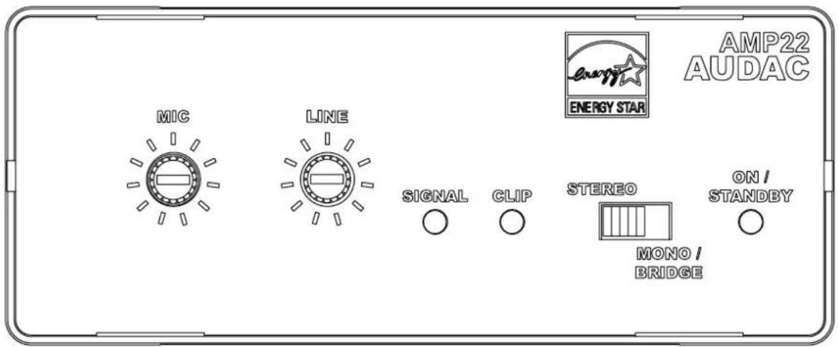
The front panel of the AMP22 contains all the control and indicator functions.
Two gain control potentiometers are provided with which the gain of the line and microphone inputs can be regulated separately and the balance between the music and speech can be set.
A slide switch provides the possibility to switch the amplifier between Stereo and Mono / Bridge mode. If this switch is set to stereo, the output will be stereo. If its set to Mono / Bridge, the Left and Right channels will be summed to a dual-mono output.
Three indication LED's for 'ON / STANDBY', 'SIGNAL' and 'CLIP' indicate the operation mode of the amplifier. The 'ON / STANDBY' LED will turn green when the device is switched ON and running. When no signal with a sufficiently high level is detected for a certain period of time, it will switch to standby mode and this LED will turn orange. The 'SIGNAL' LED will turn green when a signal with a sufficiently high level is detected and the 'CLIP' LED will start blinking when the signal reached the clipping level and the internal limiter starts working.

All necessary connections of the AMP22 are provided at the backside of the device. An overview and explanation of all the connectors and possibilities is given below.
1) 24 Volts power connector:
The 24 Volts power supply connection is provided on the left side of the AMP22's rear panel. The included power supply (PSD241) should be connected to the terminal block connectors. Pay attention to the polarity when connecting the power supply.
2) Loudspeaker output:
The loudspeakers should be connected to the 4-pins 'AMP OUT' Terminal Block connector. Depending on the position of the Stereo and Mono / Bridge switch on the front panel, the corresponding audio output will be available here. When used in Stereo mode, the left loudspeaker(s) should be connected to the two leftmost terminals and the right loudspeaker(s) should be connected to the two rightmost terminals. When used in Bridge mode, the loudspeaker(s) should be connected to the two outer terminals.
3) Remote wall panel and volume controller connections:
Two RJ45 connectors are provided for connecting Remote wall panels and external overall volume controllers. The connections on these extension ports should be made by using a simple CAT5E twisted pair (or better) cable in a straight pinout configuration. The pinout and colour coding is described on Chapter 1 of this instruction manual.
The remote wall panel connection carries the supply voltage to the wall input unit and a stereo differential audio signal from the wall input unit to the amplifier.
The audio signal coming from the remote wall panel will be proportionally mixed with the direct line and microphone inputs.
The volume controller connection carries a negative supply voltage to the external volume controller and has an input for a variable negative voltage. Depending on this voltage, the overall volume will be regulated. When no external volume controller is connected, the overall volume of the device will be defaulted to its maximum.
4) Balanced stereo line and microphone inputs:
The balanced stereo line and microphone input are performed using 3-pins terminal block connectors.
All different kinds of balanced and unbalanced line level audio sources can be connected to the line inputs. Some examples are phones, tablets, laptops ...
The microphone input provides the possibility of connecting any kind of microphone without phantom power requirement.
AMP22 Quick start guide
This chapter guides you through the setup process for a basic AMP22 project where to a line level audio source and a microphone are connected directly. An external volume controller and remote wall panel are installed remotely.

Connecting the AMP22
1) Connecting audio inputs
Connect all your audio sources to the audio inputs of the AMP22. All the direct audio inputs are performed using 3-pins terminal block connectors. For more information about the connections and wiring pinout, check Chapter 1 of this manual.
2) Connecting audio outputs
This suggested application uses a total of four loudspeakers. The AMP22 contains two speaker outputs (stereo) meaning that two speakers should be connected on every amplified output. The speakers must be connected in parallel and the load on each amplifier output channel should be 4 Ohm or higher.
3) Connecting the external units
The external (optional) wall volume controllers and remote wall panels should be connected to the corresponding RJ45 connector ports. The connections should be made by using simple CAT5E twisted pair (or better) cabling in a straight pinout configuration. The maximum cable length between the external units and the AMP22 may not exceed a total cable length of 100 meters.
4) Connecting the power supply
The included power supply should be connected to the 2-pins Euro Terminal block connector. Watch the polarity when connecting the power supply.
Configuring the AMP22
1) Adjusting the input sensitivity & volume
The configuration of the AMP22 only includes the sensitivity adjustment of the inputs and the overall volume regulation. The sensitivity of the inputs can be regulated by the two potentiometers on the front panel of the AMP22. The correct regulation depends on the signal level of the connected sources and the requirements for each specific application. The regulation should be done experimentally, making a good balance between the music signal from the audio source and the speech from the microphone.
The line and microphone level signal coming from the remote wall panel is mixed locally and the balance can be set using both potentiometers. The output level can be set using the big volume dial. This signal is mixed with the direct line and microphone inputs at equal levels.
After all sensitivity settings have been made, the overall volume control can be done using the VC3208 volume controller.
Ready
Your system is now ready for use.
| Inputs Type | 1 x stereo Balanced Line | |
| Connectors 2 x 3-pin terminal block ~ 3.81 mm | ||
| Impedance 20 kOhm | ||
| Sensitivity - 12 dBV ~ + 10dBv | ||
| Type | 1 x balanced microphone | |
| Connectors 3-pin terminal block ~ 3.81 mm | ||
| Impedance 47 kOhm | ||
| Sensitivity -50 dBV ~ -18 dBV | ||
| Outputs Type | 1 x stereo loudspeaker output | |
| Connectors 4-pin terminal block ~ 5.08 mm | ||
| Impedance Min load of 4 Ohm | ||
| RMS power 2 x 7.5 Watt @ 8 Ohm Stereo | ||
| 2 x 15 Watt @ 4 Ohm Stereo | ||
| 1 x 30 Watt @ 8 Ohm Bridge | ||
| THD+N < 0.1% | ||
| Crosstalk - 75 dB | ||
| Signal / Noise ratio >95 dB | ||
| Power consumption Standby 0.8 Watt | ||
| Energy certification | Energy Star 3.0 | |
| Efficiency 1/8 MUP | 70% | |
| MUP | 87% | |
| Cooling | Convection cooled | |
| Protection | Over heating | |
| Over load | ||
| DC short circuit | ||
| Signal limiter | ||
| Auto power down | Minimum signal | -46 dB |
| Timing | Max 90 Seconds | |
| Power supply | 24V DC | |
| NOTE: MUP stands for Maximum Undistorted Power | PSD241 switching power supply included100 - 240V AC / 47-63 Hz | |
| Dimensions (WxHxD) | 108 x 44 x 164 mm | |
| Weight | 0.40 Kg | |
| Included accessories | PSD421 | Power supply 24V / 1.67 A |
| Optional accessories | VC3208 Remote volume controller | |
| MBS1xx | Mounting bracket series | |
| CLA832 RCA / Cinch to terminal block cable | ||
| CLA835 XLR female to terminal block cable | ||
| TR3030 | 100V line transformer 30 Watt | |
| WP2xx | Universal wall panel series | |

- ADDITIONAL INFORMATION
- Introduction 05
- Precautions 06
- Chapter 1 08
- Chapter 2 010
- Chapter 3 012
- Technical specifications 014
- Mini stereo power amplifier
- READ FOLLOWING INSTRUCTIONS FOR YOUR OWN SAFETY
- CAUTION
- CAUTION RISK OF ELECTRIC SHOCK DO NOT OPEN
- CAUTION - SERVICING
- EC DECLARATION OF CONFORMITY
- WASTE ELECTRICAL AND ELECTRONIC EQUIPMENT (WEEE)
- Connections and connectors
- CONNECTION STANDARDS
- RCA:
- XLR
- 3-Pin Terminal block:
- Remote wall panel RJ45 (Audio, +24V DC)
- Volume
- controller
- RJ45:
- ATTENTION
- Overview AMP22
- 1) 24 Volts power connector:
- 2) Loudspeaker output:
- 3) Remote wall panel and volume controller connections:
- 4) Balanced stereo line and microphone inputs:
- AMP22 Quick start guide
- Connecting the AMP22
- 1) Connecting audio inputs
- 2) Connecting audio outputs
- 3) Connecting the external units
- 4) Connecting the power supply
- Configuring the AMP22
- 1) Adjusting the input sensitivity & volume
- Ready
Brand : Audac
Model : AMP22
Category : Receiver