
HD-215 - Audio Equalizer ART - Free user manual and instructions
Find the device manual for free HD-215 ART in PDF.


| Product Type | Dual Channel 15-Band Graphic Equalizer |
| Model | HD-215 |
| Number of Bands | 2 x 15, 2/3 Octave, ISO Spacing |
| Filter Type | Constant-Q, 3% Center Frequency Accuracy |
| Slide Potentiometers | 20mm Precision, Center Detented |
| Filter Range | Selectable +/-6 dB or +/-12 dB |
| Frequency Response | 20 Hz – 20 kHz, +/-0.5 dB |
| Total Harmonic Distortion (THD+N) | < 0.01% (20 Hz – 20 kHz, 0 dBu) |
| Signal-to-Noise Ratio | > 98 dB (Ref: 0 dBu, Balanced) |
| Dynamic Range | > 120 dB (Balanced) |
| Inputs/Outputs | Balanced XLR, 1/4" TRS, Euroblock (wired in parallel) |
| Input Impedance | 24 kΩ Balanced, 12 kΩ Unbalanced |
| Output Impedance | < 150 Ω Typical |
| Maximum Input Level | +22 dBm (Level Control at Center) |
| Maximum Output Level | +22 dBm Balanced (600 Ω load), +16 dBm Unbalanced (2 kΩ load) |
| High Pass Filter | 10 – 250 Hz, 12 dB/Oct |
| Low Pass Filter | 3 kHz – 40 kHz, 12 dB/Oct |
| Bypass | Passive Hard-Wire Bypass with LED Indicator |
| Clip Indicator | Red LED illuminates 6 dB below clipping |
| Ground Lift Switch | Yes, rear panel |
| Power Supply | Internal, selectable 95-125 VAC or 190-250 VAC, 50-60 Hz |
| Power Consumption | 9 Watts typical |
| Construction | All Steel Chassis |
| Dimensions (H x W x D) | 1.75" x 19" x 7.0" (4.45 cm x 48.3 cm x 17.8 cm) – 1U |
| Weight | 7.5 lbs (3.4 kg) |
| Country of Design/Manufacture | Designed in USA, Manufactured in China |
| Warranty | 1 Year Limited (see manual for details) |
Frequently Asked Questions - HD-215 ART
User questions about HD-215 ART
0 question about this device. Answer the ones you know or ask your own.
Ask a new question about this device
Download the instructions for your Audio Equalizer in PDF format for free! Find your manual HD-215 - ART and take your electronic device back in hand. On this page are published all the documents necessary for the use of your device. HD-215 by ART.
USER MANUAL HD-215 ART
IMPORTANT SAFETY INSTRUCTION – READ FIRST


This symbol, whenever it appears, This symbol, wherever it appears, alerts you alerts you to the presence of uninsulated to important operating and maintenance dangerous voltage inside the enclosure-voltage instructions in the accompanying literature. that may be sufficient to constitute a risk of shock. Please Read manual.
Read instructions:
Retain these safety and operating instructions for future reference. Heed all warnings printed here and on the equipment. Follow the operating instructions printed in this user guide.
Do not open:
There are no user serviceable parts inside. Refer any service work to qualified technical personnel only.
Power sources:
Connect the unit to mains power only of the type described in this user guide or marked on the rear panel. The power source must provide a good ground connection.
Power cord:
Use the power cord with sealed mains plug appropriate for your local main supply as provided with the equipment. If the provided plug does not fit into you outlet consult your service agent. Route the power cord so that it is not likely to be walked on, stretched or pinched by items placed upon or against.
Grounding:
Do not defeat the grounding and polarization means of the power cord plug. Do not remove or tamper with the ground connection on the power cord.
Moisture:
To reduce the risk of fire or electrical shock, do not expose the unit to moisture or use in damp or wet conditions. Do not place container of liquid on it.
Heat:
Do not locate the unit in a place close to excessive heat or direct sunlight, as this could be a fire hazard.
Locate the unit away from any equipment, which produces heat such as: power supplies, power amplifiers and heaters.
Environment:
Protect from excessive dirt, dust, heat, and vibration when operating and storing. Avoid tobacco ash, drink spillage and smoke especially that associated with smoke machines.
Handling:
Protect the controls from damage during transit. Use adequate padding if you need to ship the unit. To avoid injury to yourself or damage to the equipment take care when lifting, moving or carrying the unit.
Servicing:
Switch off the equipment and unplug the power cord immediately if it is exposed to moisture, the power cord or plug becomes damaged during a lightning storm or if smoke odor or noise is noted. Refer servicing to qualified technical personnel only.
Installation:
Install the unit in accordance with the instruction printed in the user guide.
The new ART HD-Series of Precision Graphic Equalizers have been designed and engineered to exceed extremely high standards for audio performance and functionality. These innovative, high-quality equalizers are perfect for virtually any audio application where precision frequency tailoring, reliable performance, rugged design and extremely silent processing is of the utmost priority.
Active Filter Sections
The HD-Series of Precision Graphic Equalizers feature active filter sections, which incorporate a constant-Q design. This constant-Q design, with accurate precision center frequencies, ensures that the bandwidth of every individual filter will be narrow enough to prevent unnecessary interaction between filters, yet still create an equalization curve wide enough to produce the exact and precise processing of audio frequencies the user seeks.
Precision Slide Potentiometers
The HD-Series of Precision Graphic Equalizers utilize 20mm precision slide potentiometers. These center-detented, precision faders are graphically positioned on ISO center frequencies between 25Hz-20kHz for model 215, 20Hz to 20kHz for models 131 and 231.
Independent Variable Hi and Low Pass Filtering
In order to deliver superlative performance and control, the HD-Series of Precision Graphic Equalizers incorporates independent variable Hi Pass (low cut) and Low Pass (high cut) filters. Having separate and variable precision control for both the Hi Pass and Low Pass filters, allow the user to custom tailor the audio signal to perfection.
Many competing products only feature shelving switches which have a fixed frequency point. Others do not have separate filtering for both high and low frequencies. These designs do not offer the precision or control of the ART HD-Series.
Automatic Relay Bypass
The HD-Series of Precision Graphic Equalizers also feature automatic relay bypass of audio, an essential function if power to the unit is lost. Rugged construction and solid audio performance make these equalizers particularly well suited to fixed installation as well as touring live sound systems.
Additional Controls and Indicators
The HD-Series of Precision Graphic Equalizers utilize a variable input level control, clip level indicator, ground lift switch, and selectable line voltage.
Additional features include selectable Scale Switching - (High Slider Resolution +/-12dB - or Normal Resolution (+/-6dB), active balanced and unbalanced input/output connectors, and RFI filtering.
A passive Bypass switch allows for direct comparison between the equalized and non-equalized signal for each channel.
Multiple Connectivity
The HD-Series of Precision Graphic Equalizers are connectable with a wide variety of audio devices. Each unit has three sets of input and output connectors wired in parallel. These connections include XLR, 1/4" phone, and Euroblock barrier strip connectors.
Durability by Design
The HD-Series of Precision Graphic Equalizers are designed and engineered to be durable and rugged. They are an ideal choice when the need for a robust equalizer is of paramount concern. They are designed for mounting in a standard 19" equipment rack or one of the many rack type portable cases in existence. The vertical height is 1.75 inches for the HD215 and HD131, and 3.5 inches for the HD231. The depth is 7 inches.
Precision and Quality
When considering quality equalization, the ART HD Series of Precision Graphic Equalizers are an excellent choice. They deliver extremely precise, powerfully flexible and simply great sounding equalization, with the quality features and reliable design criteria necessary for top-level audio performance.
GENERAL INFORMATION
Congratulations on the purchase of your new ART equalizer. This professional equalizer is perfect for virtually any audio application where frequency tailoring is needed. It's features include: constant Q circuitry with accurate center frequencies, selectable 6dB or 12dB range, active balanced and unbalanced input/output connectors, RFI filters, independent variable Hi Pass (low cut) and Low Pass (high cut) filters, variable input level control, passive bypass switch, clip level indicator, ground lift switch, and selectable line voltage. The unit also features automatic relay bypass of audio if power to the unit is lost or too low. Rugged construction and solid audio performance make these equalizers particularly well suited to fixed installation as well as touring live sound systems.
INSTALLATION
This series of equalizers are designed for mounting in a standard 19" equipment rack or one of the many rack type portable cases available on the market. The vertical height is 1.75 inches for the HD131 and HD215, and 3.5 inches for the HD231. The depth is 7 inches.
POWER CONNECTORS
These equalizers have internal power supplies and are designed for operation with 120 or 240 volt (as determined by the rear fuse block orientation), 50-60Hz mains supply. In new installations and portable sound systems, or any situation where the mains power is in question, it is wise to confirm the voltage and select the appropriate line voltage setting BEFORE connecting the equalizer to power sources.
INPUT/OUTPUT CONNECTIONS
The HD series graphic equalizers have 3 sets of input and output connectors wired in parallel: XLR, 1/4" phone, and Euroblock barrier strip connectors. Only one of the 3 inputs should be used per channel. Any combination of output connectors may be used.
XLR connections are balanced where pin 2 is High (+), pin 3 is Low (-), and pin 1 is ground.
1/4" Phone connections may be used balanced or unbalanced. When balanced, the tip is High (+), the ring is Low (-) and the sleeve is ground. To use unbalanced use a mono 14 " phone cable, this will automatically ground the ring to the sleeve.
EUROBLOCK CONNECTIONS
Insert the wires, and then snug down with the set screw. The entire barrier strip can be removed for quick service without disconnecting the individual wires.
SIGNAL LEVELS
Signal levels from -10dBu to +4dBu are considered normal with maximum levels of approximately +22dBu balanced or +16dBu unbalanced. Do not connect microphones directly to the equalizer. Most Microphones, as well as instrument pickups, require a preamp to get the signal level up to a line level. The outputs of the equalizer are also designed to connect into line level inputs and should not be connected into sensitive Microphone or Instrument Inputs for best results.
CHASSIS GROUNDING
The equalizers are equipped with a rear panel Ground Lift switch. This should normally be set to the Ground position. After set up, if your system exhibits excessive hum or buzzing, the problem may be a due to a ground differential between your equalizer and other equipment in the same system. The Ground Lift switch lets you try several combinations to minimize system hum.
NOTE: ALWAYS TURN YOUR AMPLIFIERS DOWN BEFORE CHANGING GROUNDS.
Try different combinations of lifting grounds on units that are supplied with ground lift switches or make sure all chassis are connected to earth ground, either through the AC Power cord ground or by the front panel rack mount screws.
If the HD series equalizer is mounted in a grounded rack of equipment, the ground to the case of the equalizer may be lifted to prevent multiple ground paths, which may cause a ground loop to occur.
OPERATING INSTRUCTIONS
Before starting to equalize your sound system there is some information you should know and procedures you should follow. Your equalizer is equipped with a bypass switch. The bypass switch, when activated, lights the bypass LED and cancels all equalization settings while allowing signal to flow directly through the unit at unity gain.
Also included is a range selection switch with LED indicators, +/-6dB = green, +/-12dB = yellow. In addition to the range selection switch there is an output level control potentiometer. The level control operates between off and +6dB. Note: If there is too much gain, your equalizer has a red LED Clip indicator that illuminates when signals are within 6dB of clipping. If the Clip LED flashes occasionally, this is okay, but if this LED is steadily on you should reduce the level control.
INITIAL SET UP
Here are some tips to help you with the initial set up:
- Set channel output levels to the center detent 0dB on the front panel.
- Select the Bypass switch to bypass the equalizer (Note: The red LED is on).
- Set the frequency slide controls to the center detent (0dB).
- Set the Hi Pass filter to 10Hz and the Low Pass filter to 40kHz.
- Select the +/-6dB range (Note: The green LED is on).
- Apply signal to the system and if the Clip LED is on, reduce your signal to the unit.
- Release the bypass switch (Note: The red LED is off).
- If the Clip LED is on, turn down the Output Level control.
- You may now start equalizing your system.
- If you do not have enough equalization control, switch the range switch to the 12dB setting.
FRONT PANEL CONTROLS
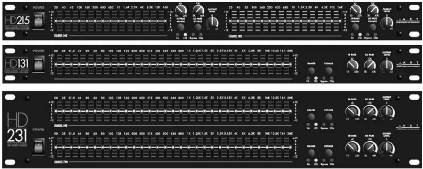
1. POWER SWITCH
To turn the equalizer ON or OFF, press the upper or lower portion of this button. CAUTION: Always turn on your equalizer BEFORE your power amplifiers are turned on, and always turn off your equalizer AFTER your power amplifiers have been turned off.
2. FILTER LEVEL CONTROLS
Each of these sliders controls the signal level of each of the 31 (or 15) bandpass filters. A detent at the center position helps center the controls for a flat response.
3. FILTER RANGE SWITCH & INDICATORS
The gain range of the filter sliders is switchable (as a group) from +/-6dB to +/-12dB for maximum boost/cut capability. At +/-6dB the green LED will illuminate, and at +/-12dB the yellow LED will illuminate.
4. BYPASS SWITCH & CLIP INDICATOR LED
Bypass Switch: When the red Bypass LED is illuminated, this indicates that the unit or channel is in the bypass mode. Signal is routed directly from the input to the output without passing through any circuitry (often referred to as "hard-wire bypass"). Use this switch to compare equalized and unequalized material, or to bypass the EQ section in the event of total unit failure.
Clip Indicator: - This red LED illuminates if any section of the equalizer is near clipping. Occasional flickering of this LED is acceptable, but if it remains on more than intermittently you should reduce the output level of the preceding equipment or, if that is not possible, turn down the equalizer's level control to avoid audible distortion.
5. HI PASS FILTER (LOW-CUT FREQUENCY CONTROL)
To cut down on unwanted low frequency signals, this control determines the roll-off frequency of the Hi-Pass Filter (HPF). The roll-off frequency can be adjusted from 10Hz to 250Hz by turning this knob. Because of its high roll-off slope, the HPF can be efficiently used to cut down hum and low frequency noise from preceding instruments, or to reduce low frequency resonances, when speakers are installed in an enclosed acoustic environment. It is also very effective at removing power robbing and potentially destructive rumble.
6. LOW PASS FILTER (HIGH-CUT FREQUENCY CONTROL)
To cut down on unwanted high frequency signals, this control determines the roll-off frequency of the Low-Pass Filter (LPF). The roll-off frequency can be adjusted from 3kHz to 40kHz by turning the knob. Because of its high roll-off slope, the LPF can be effectively used to cut down the high frequency noise from preceding instruments, or roll-off excessive high frequency sounds to obtain a more natural sound in some acoustic situations.
7. LEVEL CONTROL
This controls the output signal level from the equalizer. Turn this control down if the Clip LED illuminates steadily (meaning too strong an input signal). Unity gain can be set by adjusting this knob so that as you toggle the Bypass switch the overall level sounds the same.
Signal levels should be kept normalized through the equalizer. That is, the signal level, when bypassed, should be the same (or a little lower) than when active. One reason for this is if the equalizer loses power (which causes the unit to go into bypass), the signal will be equal or lower than the active eq gain. This will ensure that a signal with undesirably higher levels will not be passed inadvertently.
REAR PANEL CONNECTORS & CONTROLS



8. POWER CORD
This cord is used to connect the AC power source to your equalizer. CAUTION: Equipment for USA installation includes a power cord with a three pin polarized plug. DO NOT REMOVE THE CENTER GROUNDING PIN.
9. FUSE HOLDER
This fuse holder contains the AC primary fuse. This fuse should be replaced with the same type fuse if it is blown. If they continuously blow, stop replacing fuses and refer servicing to qualified personnel. CAUTION: After checking the AC supply voltage, be sure that the correct fuse is in the fuse holder - 0.5Amp for 95-125VAC, as well for 220-240VAC. The orientation of the fuse holder determines the line voltage range and is labeled on the rear of the holder. When changing the fuse, make sure that you insert the holder in the correct orientation for your local line voltage.
10. GROUND LIFT SWITCH
This switch is used to disconnect signal ground from the mains and chassis earth ground. You may set the switch to the LIFT position if "Hum", caused by a ground loop, can be heard at the speakers.
11. INPUT/OUTPUT CONNECTORS
1/4 TRS
The TRS (Tip Ring Sleeve) connector is balanced and wired as Tip = High (+), Ring = Low (-), and Sleeve = Ground.
XLR
The XLR input connector is balanced and wired as Pin 2=High (+), Pin 3=Low (-), and Pin 1=Ground.
EURO BLOCK
HD131

HD 215, HD231

CAUTION: Only one input option should be chosen for audio connection at the same time.
FOR BALANCED CONNECTIONS
Wire the connectors as follows:
Phone Jack Connection
tip = High (+)
ring = Low (-)
sleeve = ground
FOR UNBALANCED CONNECTIONS
Use 1/4 inch tip-ring-sleeve or mono phone plug connectors wired as follows:
Phone Jack Connection
tip = High (+)
ring = no connection
sleeve = ground
APPLICATIONS
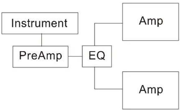
Graphic equalizers may be used wherever modification of the frequency contour of a sound system is needed. A graphic equalizer is a solution to any number of sound problems or creative urges.
| Typical reinforcement application of a two channel equalizer | Equalization of audio signals from a mixer |
 |  |
| Equalization of a musical instrument | Equalization of an effects loop |
 |  |
WARRANTY INFORMATION
Limited Warranty
Applied Research and Technology will provide warranty and service for this unit in accordance with the following warrants:
Applied Research and Technology, (A R T) warrants to the original purchaser that this product and the components thereof will be free from defects in workmanship and materials for a period of one year from the date of purchase. Applied Research and Technology will, without charge, repair or replace, at its option, defective product or component parts upon prepaid delivery to the factory service department or authorized service center, accompanied by proof of purchase date in the form of a valid sales receipt.
Exclusions
This warranty does not apply in the event of misuse or abuse of the product or as a result of unauthorized alterations or repairs. This warranty is void if the serial number is altered, defaced, or removed.
A R T reserves the right to make changes in design or make additions to or improvements upon this product without any obligation to install the same on products previously manufactured.
A R T shall not be liable for any consequential damages, including without limitation damages resulting from loss of use. Some states do not allow limitations of incidental or consequential damages, so the above limitation or exclusion may not apply to you. This warranty gives you specific rights and you may have other rights, which vary from state to state.
For units purchased outside the United States, an authorized distributor of Applied Research and Technology will provide service.
SERVICE
The following information is provided in the unlikely event that your unit requires service.
1) Be sure that the unit is the cause of the problem. Check to make sure the unit has power supplied, all cables are connected correctly, and the cables themselves are in working condition.
2) If you find the unit to be at fault, write down a complete description of the problem, including how and when the problem occurs. Please write down a description of your complete setup before calling Customer Service.
3) Contact our Customer Service department at (716) 297-2920 for your Return Authorization number or questions regarding technical assistance or repairs. Customer Service hours are 9:30 AM to 5:00 PM Eastern Time, Monday through Friday.
4) Pack the unit in its original carton or a reasonable substitute. The packing box is not recommended as a shipping carton. Put the packaged unit in another box for shipping. Print the RA number clearly on the outside of the shipping box. Print your return shipping address on the outside of the box.
5) Include with your unit: a return shipping address (we cannot ship to a P.O. Box), a copy of your purchase receipt, a daytime phone number, and a description of the problem.
6) Ship only your unit (keep your manual!) to:
Yorkville
Sound
4625 Witmer Industrial Estates
Niagara Falls, New York 14305
ATTN: REPAIR DEPARTMENT
RA#
SPECIFICATIONS:
EQUALIZER
Bands 2 x 15, 2/3 Octave, ISO Spacing (HD215)
1 x 31, 1/3 Octave, ISO Spacing (HD131)
2 x 31, 1/3 Octave, ISO Spacing (HD231)
Type / Accuracy Constant Q, 3% Center Frequency
Travel 20mm (Positive Center Detent)
Range +/-6dB or +/-12dB (Selectable)
Overall Gain Range Off to +6dB (Unbalanced out) Sliders Centered
Off to +12dB (Balanced out) Sliders Centered
INPUTS
Type Active Balanced/Unbalanced
Connectors 3-Pin XLR, 1/4" TRS (Balanced), Euroblock
Impedance 24k Ohms Balanced; 12k Ohms Unbalanced
Maximum Level +22dBm (Level Control at Center)
OUTPUTS
Type Active Balanced/Unbalanced
Connectors 3-Pin XLR, 1/4" TRS (Balanced), Euroblock
Impedance Typical <150 Ohms
Maximum Level +22dBm (Balanced) (600 Ohm load)
+16dBm (Unbalanced) (2k Ohm load)
RFI filters Yes
Passive Bypass Switches Yes
Overload LED Threshold 6 dB (Below Clipping), (all filters set to flat)
High Pass Filter 10-250Hz, 12dB/Oct
Low Pass Filter 3k-40kHz, 12dB/Oct
Frequency Response 20-20kHz, +/-0.5dB
THD + Noise less than .01% (20Hz-20kHz, 0dBu)
IM Distortion (SMPTE) 0.005%
Signal to Noise Ratio greater than 98dB, Ref: 0dBu, (Balanced) HD215
greater than 95dB, Ref: 0dBu, (Balanced) HD131/231
20Hz - 20kHz, unweighted.
Headroom +22dB, Ref, 0dBu, (Balanced) (+/-6dB and +/-12dB range)
Dynamic Range greater than 120dB, (Balanced) HD215
greater than 117dB, (Balanced) HD131/231
Channel Separation greater than 60dB
Common Mode Rejection 50dB typical
| LINE VOLTAGE | 95-125VAC, 50/60Hz |
| 190-250VAC, 50Hz |
| INPUT AC POWER | 9 Watts (HD131 and HD215), 14Watts (HD231), typical |
| CONSTRUCTION | All | Steel | Chassis |
| SIZE | 1.75" H *19" W *7.0" D (1U) (HD131 and HD215) |
(4.45cm * 48.3cm * 17.8cm)
3.5" H *19" W *7.0" D (2U) (HD231)
(8.9cm * 48.3cm * 17.8cm)
| WEIGHT | 7.5 lbs (3.4 kg). (HD131 and HD215) |
12 lbs (5.4 kg). (HD231)

APPLIED RESEARCH AND TECHNOLOGY
APPLIED RESEARCH & TECHNOLOGY 215 TREMONT STREET ROCHESTER, NEW YORK 14608 USA
(585) 436-2720 – Voice
(585) 436-3942 - Fax
www.artproaudio.com
E-mail: cserve@artproaudio.com
HD-SERIES
Model HD131 - SINGLE CHANNEL 31 BAND 1/3 OCTAVE GRAPHIC EQUALIZER
Model HD215 - DUAL CHANNEL 15 BAND 2/3 OCTAVE GRAPHIC EQUALIZER
Model HD231 - DUAL CHANNEL 31 BAND 1/3 OCTAVE GRAPHIC EQUALIZER
HD-SERIES HD-5004-100


- IMPORTANT SAFETY INSTRUCTION – READ FIRST
- Read instructions:
- Do not open:
- Power sources:
- Power cord:
- Grounding:
- Moisture:
- Heat:
- Environment:
- Handling:
- Servicing:
- Installation:
- Active Filter Sections
- Precision Slide Potentiometers
- Independent Variable Hi and Low Pass Filtering
- Automatic Relay Bypass
- Additional Controls and Indicators
- Multiple Connectivity
- Durability by Design
- Precision and Quality
- GENERAL INFORMATION
- INSTALLATION
- POWER CONNECTORS
- INPUT/OUTPUT CONNECTIONS
- EUROBLOCK CONNECTIONS
- SIGNAL LEVELS
- CHASSIS GROUNDING
- NOTE: ALWAYS TURN YOUR AMPLIFIERS DOWN BEFORE CHANGING GROUNDS.
- OPERATING INSTRUCTIONS
- INITIAL SET UP
- FRONT PANEL CONTROLS
- POWER SWITCH
- FILTER LEVEL CONTROLS
- FILTER RANGE SWITCH & INDICATORS
- BYPASS SWITCH & CLIP INDICATOR LED
- HI PASS FILTER (LOW-CUT FREQUENCY CONTROL)
- LOW PASS FILTER (HIGH-CUT FREQUENCY CONTROL)
- LEVEL CONTROL
- REAR PANEL CONNECTORS & CONTROLS
- POWER CORD
- FUSE HOLDER
- GROUND LIFT SWITCH
- INPUT/OUTPUT CONNECTORS
- 1/4 TRS
- XLR
- EURO BLOCK
- FOR BALANCED CONNECTIONS
- FOR UNBALANCED CONNECTIONS
- APPLICATIONS
- WARRANTY INFORMATION
- Limited Warranty
- Exclusions
- SERVICE
- SPECIFICATIONS:
- EQUALIZER
- INPUTS
- OUTPUTS
- APPLIED RESEARCH AND TECHNOLOGY
- APPLIED RESEARCH & TECHNOLOGY 215 TREMONT STREET ROCHESTER, NEW YORK 14608 USA
Brand : ART
Model : HD-215
Category : Audio Equalizer