Freqbox MF-107 - Uncategorized Moog - Free user manual and instructions
Find the device manual for free Freqbox MF-107 Moog in PDF.


| Brand | Moog |
| Model | MF-107 FreqBox |
| Product Type | Analog Effects Module (Stompbox) |
| Dimensions | 9 x 6 x 2.5 inches (22.9 x 15.2 x 6.4 cm) |
| Net Weight | 2 lbs (0.91 kg) |
| Power Supply | +9VDC, 300 mA, tip-positive (included) |
| Audio Input | 1/4" TS, impedance 1 MΩ, accepts -16 dBm to +4 dBm |
| Audio Output | 1/4" TS, impedance 1 kΩ, nominal -4 dBm, max +10 dBm |
| CV Inputs | 5 x 1/4" TRS (Freq, Wave, Env Amt, FM Amt, Mix) – Expression pedal or 0-5V CV (Freq accepts -5V to +5V) |
| CV Outputs | Env Follower CV Out (0-5V) and Oscillator Direct CV Out (±2.5V) |
| Front Panel Controls | Drive, Output Level, Mix, Freq, Wave, Env Amount, FM Amount, Sync On/Off switch, Bypass switch |
| Indicators | Level LED (3-color: off/green/yellow/red), Bypass LED (red=bypass, green=active) |
| VCO Range | 25 Hz to 1.6 kHz (front panel); extended to sub-audio to 20 kHz via CV |
| VCO Waveforms | Triangle, Sawtooth, Square, Pulse (continuously variable) |
| Key Features | Hard Sync, Frequency Modulation (FM), Envelope Follower with VCA, voltage-controllable parameters, buffered bypass |
| Construction | Black panel with hardwood sides |
| Warranty | 1 year limited warranty (return-to-factory) |
Frequently Asked Questions - Freqbox MF-107 Moog
User questions about Freqbox MF-107 Moog
0 question about this device. Answer the ones you know or ask your own.
Ask a new question about this device
Download the instructions for your Uncategorized in PDF format for free! Find your manual Freqbox MF-107 - Moog and take your electronic device back in hand. On this page are published all the documents necessary for the use of your device. Freqbox MF-107 by Moog.
USER MANUAL Freqbox MF-107 Moog
Understanding and Using your
moogerfooger®
MF-107 FreqBox ^TM
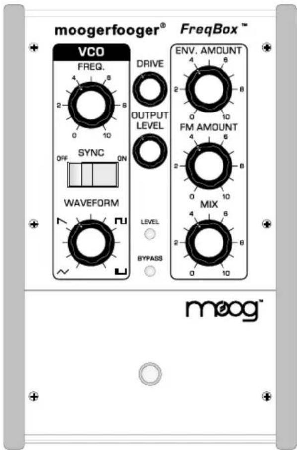
TABLE OF CONTENTS
Introduction......2
Getting Started Right Away!......4
Basic Applications....6
FreqBox Theory....10
FreqBox Functions....16
Advanced Applications....21
Technical Information....24
Limited Warranty....25
MF-107 Specifications....26
Welcome to the world of moogerfooger® Analog Effects Modules. Your Model MF-107 FreqBox™ is a rugged, professional-quality instrument, designed to be equally at home on stage or in the studio. Its great sound comes from the state-of-the-art analog circuitry, designed and built by the folks at Moog Music in Asheville, NC.
Your MF-107 FreqBox is a direct descendant of the original modular Moog® synthesizers. It contains several complete modular synth functions: a voltage-controlled oscillator (VCO) with variable waveshape, capable of being hard synced and frequency modulated by the audio input, and an envelope follower which allows the dynamics of the input signal to modulate the frequency of the VCO. In addition the amplitude of the VCO is controlled by the dynamics of the input signal, and the VCO can be mixed with the audio input. All performance parameters are voltage-controllable, which means that you can use expression pedals, MIDI-to-CV converter, or any other source of control voltages to 'play' your MF-107. Control voltage outputs mean that the MF-107 can be used with other moogerfoogers or voltage controlled devices like the Minimoog Voyager® or Little Phatty® synthesizers.
While you can use it on the floor as a conventional effects box, your MF-107 FreqBox is much more versatile and its sound quality is higher than the single fixed function "stomp boxes" that you may be accustomed to. You will find that your FreqBox is a deep musical resource. It will give you an amazing variety of new sounds and will become your creative companion as you explore its functions.
This manual begins with a "quick start" section that will get you started without reading the whole manual – certainly a new device must be used right away! Keep in mind that the MF-107 FreqBox is a complex device, so we recommend you read and understand
the complete user's manual to unlock its fullest potential. Included in this manual is a section describing the theory of operation, a tour and explanation of the front panel controls and rear panel connections, and tips on usage both basic and advanced. A section describing the product's technical specifications and information about your limited warranty is at the end of the manual.
The Story Behind the FreqBox
Back in 2004, I had an idea for an oscillator that could hard sync to any input signal. Thinking that this might be a really cool and unique idea, I sketched it up and brought it to Bob Moog. I asked him if such an idea would be feasible. He looked me in the eye and produced one of his famous belly-laughs. He pointed over to our engineering technician at the time, Mark Kline. Mark had brought him this same idea a week or so earlier and had already begun building a feasibility prototype. I compared my sketch to the plans for the prototype. Lo and behold they were the same except for a few minor differences – all without either of us discussing this idea with each other! Bob loved this kind of occurrence, as he felt it revealed the interconnectedness of all things. He said the idea "must be in the air".
Mark soon left Moog Music to pursue a career in architecture, and we put aside "The Big Sync", as we called it then, to work on other projects. In 2006 it was time to revisit the design and add a few things, like the dynamic control of the oscillator volume, envelope follower modulation of the VCO and frequency modulation from the input signal, and the FreqBox was born. In Bob's honor, I recommend connecting with your new Moogerfooger and exploring the outer regions of its sonic space. Enjoy!
Steve Dunnington, Moog Music Inc.
GETTING STARTED RIGHT AWAY!
We have never known musicians who don't want to try a new effect out before reading the entire manual, so here is a quick guide to get you started with your new FreqBox:
1) Inspect the carton and its contents: The MF-107 comes with the Moogerfooger, a +9VDC, 300 mA, tip-positive power supply, and this manual. Save the box and packing material in case you ever need to ship your moogerfooger! Make sure that the power supply is rated for the line Voltage of your country: 120 VAC for the USA, 100 VAC for Japan, or 220 VAC for Europe or most other countries.
2) Connections: Connect your instrument to the FreqBox AUDIO
INPUT. Connect the AUDIO OUTPUT of the FreqBox to your amp. Connect your Expression Pedal (such as the Moog EP-1 or EP-2) to the FREQ input (see figure 1). An expression pedal is highly recommended, especially for using the FreqBox with a guitar.
3) Set up the Front Panel/Amp: Set all the rotary controls on the FreqBox as shown in figure 2. Make sure the
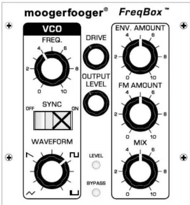
Figure 2 Basic Panel Setup
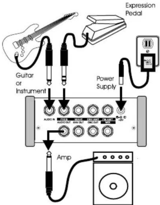
Figure 1 - Basic Connections
Expression pedal is in the heel position. Turn down the volume of your amplifier.
4) Power up/Bypass: Connect the moogerfooger power supply to the FreqBox power connector. The Bypass indicator will light up. I RED means the effect is OFF and GREEN means the effect is ON.
5) Set levels: Turn on your amplifier. Make sure the Bypass indicator is RED. Play your instrument and adjust the volume of the amplifier so it is at a comfortable level. Press the Bypass switch and the Bypass indicator will change to GREEN which means the effect is active.
6) Play: Now play a little on your instrument. If necessary adjust the Drive control to match the level of the effected signal to the bypassed signal. ***The most predictable results will come from playing single note riffs or melodies. This is especially true when the Sync switch is ON***. You can use the expression pedal to sweep the frequency, which in this setting will sound something like a grungy wah-wah type effect that also responds to the dynamics of your playing. To hear more of the effect, increase the Mix setting.
For your first experiment, try turning the FM Amount down. The effect will now sound smoother. This sounds like a really fuzzed-out wah sound with the expression pedal.
Now try turning the FM amount all the way up, and turn the Sync OFF. You'll get a sizzly sound that is not clearly pitched. Turn the Waveform down all the way and the effect gets less sizzly. As you turn the Waveform control back up you'll hear the sound become increasingly complex.
Now try turning FM amount back down, and turn the Env Amount control all the way down. When you play you'll hear just the VCO at a single pitch. You can play the frequency of the Oscillator with your expression pedal for a "foot theremin" effect.
7) READ THE MANUAL TO FULLY UNDERSTAND THIS
DEVICE!!! The FreqBox has a lot more possibilities once you understand how it works. If you want to explore the FreqBox further before reading the manual, skip ahead to Basic Applications on page 6. It contains simple diagrams and descriptions of ways to setup the FreqBox. If you want to know about the Theory of the FreqBox, it's covered in the section called FreqBox Theory starting on page 10. If you are planning on using the FreqBox with other effects, or as an extra oscillator for your Minimoog Voyager® or modular synth system check out the section about this in Advanced Applications on page 21.
BASIC APPLICATIONS
The following are diagrams of basic settings of the FreqBox. They are good staring points for learning how to use the FreqBox. For each setup, set the knobs on your FreqBox to the position shown. Adjust the Drive and Output Level controls to match your input signal. Make sure the Bypass LED is GREEN to hear the effect.
Basic Sync Setup:
This setup is best used with an expression pedal plugged into the Freq. input and clean, single note lines. The expression pedal can be used to sweep the frequency of the VCO slowly for slow harmonic sweeps, or quickly and rhythmically for an effect reminiscent of a wah wah. Note that with the expression pedal in the heel position, notes above a low A on a guitar are choked out. Use the expression pedal to keep the VCO frequency above the note that you are playing. This is the basic setup for a classic hard sync sound.
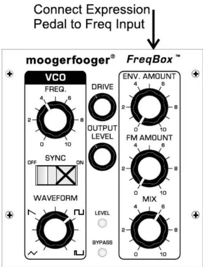
Figure 3 - Basic Sync Setup
Sync+FM
This setup is the same as the previous, but adds a dose of FM, which gives the sound an extra bit of growl, especially when the frequency of the VCO is swept with the Freq control, or an expression pedal plugged into the Freq Input.
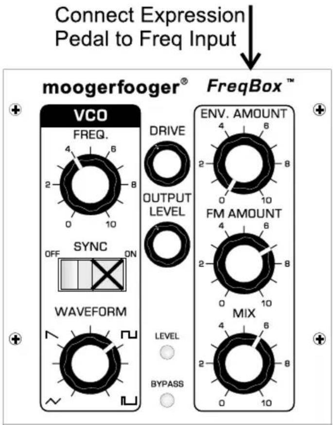
Figure 4 - Sync+FM
AutoSyncSweep
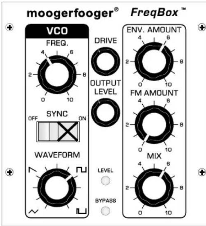
Figure 5 - AutoSyncSweep
This setup uses the dynamics of your playing to modulate the frequency of the VCO using the envelope follower. Hard playing causes the frequency to go up and you get more sweep of the VCO from the envelope follower. This is a really good setup to use with guitar, reminiscent of an auto-wah type of effect. The key to this setup is in setting the Drive control (not too much red showing on the Level indicator) and the Envelope Amount control. Using an expression pedal to control the frequency sounds good with this setup.
Drone
This is a fun setup for modal jams or morning ragas – it uses just the sound of the VCO set to one frequency, tuned to the key that you're playing in. If you're in A, just tune the VCO to A with the Freq control. The drone sound can be fattened up if detuned a little bit from a bass note in the key. Setting the Mix control is important for a nice balance between the instrument sound and the VCO sound.
Tune VCO Freq to the key of your jam.
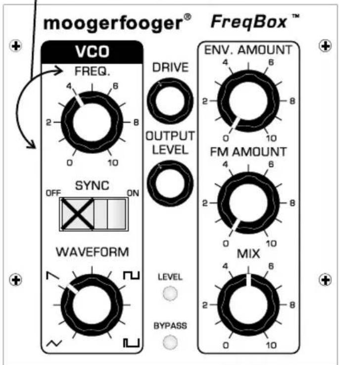
Figure 6 - Drone
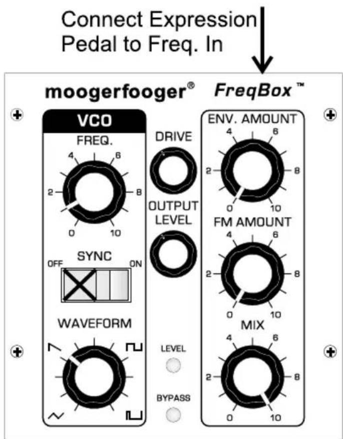
Figure 7 - Foor Theremin
Foot Theremin
This is basically the same as the previous setup with the addition of an expression pedal to control the VCO frequency. It's difficult to control the frequency of the VCO precisely with an expression pedal, but quite fun to attempt. Try playing staccato for synth-like bleeps and bloops, or play sustained tones with wild expression pedal movements for instant psychedelic freakout sounds a la the "Whole Lotta Love" breakdown (just add a little echo).
FM Gongs
This is a setup that just uses FM for sounds somewhat reminiscent of gongs. It works well with slow, guitar-like signals plucked and allowed to fade out. Don't play too hard or the gongs may sound flatulent.
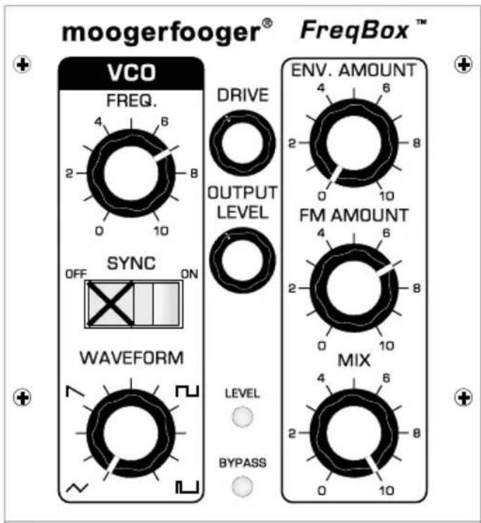
Figure 8 - FM Gongs
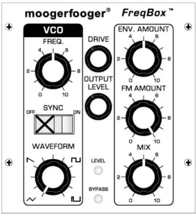
Figure 9 - FM Sizzler
FM sizzler
This is a weird one – good for otherworldly synth-type sweeps. An expression pedal controls the VCO frequency. Try starting with the expression pedal in the toe position and sweep the frequency down slowly as you play – you’ll hear a symphony of sidebands swirling around...
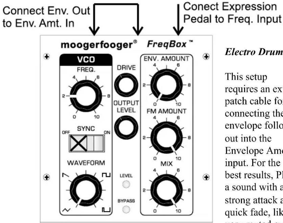
Figure 10 - Electro Drumz
Electro Drumz
This setup requires an extra patch cable for connecting the envelope follower out into the Envelope Amount input. For the best results, Play a sound with a strong attack and a quick fade, like a very muted guitar string plucked hard with a pick. This gives a REALLY sharp sweep of the VCO frequency by the envelope follower so that you can make really percussive sounds. The brightness of this percussive sound is controlled by how hard you play. The expression pedal allows you to sweep from deep sounding percussive sounds in the heel position to really high pitched sizzly sounds in the toe position.
FREQBOX THEORY
Fundamentals of sound
Let's start with some definitions. Please read this section carefully, as it will help you to understand the basic ideas underlying the FreqBox.
Sound is a vibration of the air. The speed of vibration is called the frequency. It is measured in Hertz (Hz). One Hz is one cycle per second. We hear vibrations from 20 Hz to 20,000 Hz. The lowest A on a piano is usually tuned to 27.5 Hz, and the highest C is tuned to 4186 Hz. Each time you double a frequency, you hear a change of an octave. So the A's on a piano are tuned from low to high to 27.5 Hz, 55 Hz, 110 Hz, 220 Hz, 440 Hz, 880 Hz, 1760 Hz, and 3520 Hz. That's seven octaves. The loudness of a sound is called it's amplitude. This relates to the strength of
the vibration in the sound.
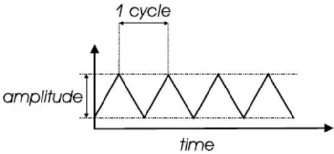
Different instruments playing the same pitch sound different, like an oboe and a violin playing A440. That's because musical sounds generally have many frequency components. They're called harmonics, or overtones, or partials. The harmonics of a pitched musical sound are related to the pitch we hear, called the fundamental, by simple relationships, 1X (fundamental, or first harmonic) 2X(2nd harmonic), 3X (3rd harmonic), 4X (4 ^th harmonic), 5X (5 ^th harmonic), 6X (6 ^th harmonic), and so on. These relationships define what we call the harmonic series. The presence and strength of different harmonics is what gives a sound its characteristic tone color, or timbre. We can represent a musical sound as a waveform. The waveform is a time graph of the actual shape of the vibration. See Figure 11.
The waveform of a single harmonic is called a sine wave. It is the simplest type of periodic vibration there is. If you listen to a 500 Hz sine wave, you hear a pitch nearly an octave above
line
| time | amplitude | | ---- | --------- | | 0 | 0 | | 1 | 1 | | 2 | 0 | | 3 | 1 | | 4 | 0 | | 5 | 1 | | 6 | 0 | | 7 | 1 | | 8 | 0 | | 9 | 1 | | 10 | 0 | | 11 | 1 | | 12 | 0 | | 13 | 1 | | 14 | 0 | | 15 | 1 | | 16 | 0 | | 17 | 1 | | 18 | 0 | | 19 | 1 | | 20 | 0 | | 21 | 1 | | 22 | 0 | | 23 | 1 | | 24 | 0 | | 25 | 1 | | 26 | 0 | | 27 | 1 | | 28 | 0 | | 29 | 1 | | 30 | 0 | | 31 | 1 | | 32 | 0 | | 33 | 1 | | 34 | 0 | | 35 | 1 | | 36 | 0 | | 37 | 1 | | 38 | 0 | | 39 | 1 | | 40 | 0 | | 41 | 1 | | 42 | 0 | | 43 | 1 | | 44 | 0 | | 45 | 1 | | 46 | 0 | | 47 | 1 | | 48 | 0 | | 49 | 1 | | 50 | 0 | | 51 | 1 | | 52 | 0 | | 53 | 1 | | 54 | 0 | | 55 | 1 | | 56 | 0 | | 57 | 1 | | 58 | 0 | | 59 | 1 | | 60 | 0 | | 61 | 1 | | 62 | 0 | | 63 | 1 | | 64 | 0 | | 65 | 1 | | 66 | 0 | | 67 | 1 | | 68 | 0 | | 69 | 1 | | 70 | 0 | | 71 | 1 | | 72 | 0 | | 73 | 1 | | 74 | 0 | | 75 | 1 | | 76 | 0 | | 77 | 1 | | 78 | 0 | | 79 | 1 | | 80 | 0 | | 81 | 1 | | 82 | 0 | | 83 | 1 | | 84 | 0 | | 85 | 1 | | 86 | 0 | | 87 | 1 | | 88 | 0 | | 89 | 1 | | 90 | 0 | | 91 | 1 | | 92 | 0 | | 93 | 1 | | 94 | 0 | | 95 | 1 | | 96 | 0 | | 97 | 1 | | 98 | 0 | | 99 | 1 | | | |Figure 11: a basic waveform graph
middle C, with a mellow, muted quality, like a flute or a whistle. A 100 Hz sine wave also sounds mellow and muted, but its pitch is more than an octave below middle C.
VCOs
The heart of the FreqBox is a Voltage Controlled Oscillator, or VCO. The FreqBox VCO is a descendant of the same oscillators used in the Moog Voyager and Little Phatty® synthesizers. An oscillator is a type of circuit that vibrates electronically such that the changes in voltage (electrical potential) can be used as a sound source. An oscillator circuit doesn’t produce sound until it is changed from an electrical signal to a mechanical signal, usually by the means of loudspeakers. The sound made by an analog oscillator circuit is most often a very simple signal because it has very simple vibrations.
The "voltage controlled" part of a VCO refers to the fact that in this circuit a control voltage (CV) determines the frequency of the oscillator. A steady CV will result in a steady pitch, while a changing CV will cause a change in frequency. The FreqBox has a front panel Frequency control changing that generates a voltage that increases as the control is turned clockwise. This causes the frequency of the FreqBox VCO to rise.
VCO Waveforms
The timbre of the VCO is determined by its waveform. As defined earlier, a waveform is related to the timbre, and the number of harmonics in a sound. In many musical sounds, waveforms are really complex, and change a lot over time, often both in frequency, timbre and amplitude. This is not so with the raw signal of a VCO. Unlike most musical instruments, a VCO is always vibrating. It will vibrate without changing frequency, timbre, or amplitude with no change at its control input. A VCO waveform can be represented with really simple graphs. There are various types of waveforms, we will talk about the waveforms that are produced by the
FreqBox's VCO and how they sound.
One basic waveform is the sawtooth
wave.(figure 12A). The
start of the waveform's
cycle is a rapid jump
from low to high then the waveform ramps down to
Figure 12: VCO Waveforms
the bottom. A sawtooth wave contains all the harmonics of the harmonic series, with the amplitude of each harmonic decreasing by the same ratio it increases, i.e. the 2^nd harmonic is 2X the frequency of the fundamental, but 12 the amplitude of the fundamental. The rest of the harmonics continue in this manner. Because of all these harmonics, the sawtooth wave can be described as very bright and buzzy.
Another waveform is the square wave (figure 12B). A cycle of a square wave has two equally timed portions (the high and low), making it a symmetrical waveform. It has only odd harmonics (3X, 5X, 7X, etc), with each harmonic following the same basic amplitude relationship as the sawtooth wave (The 3^rd harmonic is 3X the fundamental frequency and 1/3 the fundamental amplitude). The square wave sounds bright but also a little hollow (somewhat like a clarinet).
A square wave is a type of rectangular wave (figure 12C), it happens to be symmetrical. The width of the high portion of a rectangular wave is known as the pulse width, and can be expressed as a percentage. For instance, a square wave has a pulse width of 50%. When a rectangular wave is asymmetrical, it is called a pulse wave. As the pulse width gets much smaller or larger than 50% the sound becomes thin and reedy,
yet bright. Pulse waves contain all harmonics, but the amplitude of the harmonics varies with pulse width.
A triangle wave is a symmetrical waveform (figure 12D). As it turns out all symmetrical waveforms have only odd harmonics. With a triangle wave the amplitude of the harmonics decrease much faster than a square wave (exponentially), which gives it a much mellower sound, closer to a sine wave than a square wave.
Hard Sync
The term Hard Sync is a synthesis term that traditionally refers to resetting the start of an oscillator's waveform at the frequency of another oscillator, called the Master Oscillator. It is called Sync because the oscillator that is restarted takes on the frequency of the Master oscillator, seemingly "synchronized" in frequency (see figure 13), yet with a new more complex waveform. The effect is strongest as long as the Master Oscillator frequency
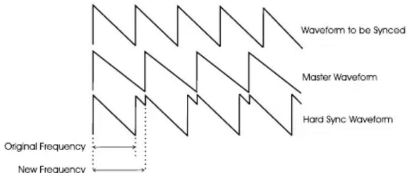
Figure 13 - Hard Sync
is lower than the oscillator that is reset. In fact, if the Master Oscillator is much higher in frequency than the synced oscillator, the synced oscillator signal becomes weak and possibly inaudible. This is a really important concept when using the FreqBox!
In the FreqBox, instead of using a second Oscillator as the Master, the signal at the input is used to reset the FreqBox's VCO waveform. This means the following are very important:
- The simpler the input signal, the cleaner and more predictable the Synced oscillator will be.
- If the input signal is not lower in frequency than the FreqBox VCO, then you may not hear anything at the output!
Hard Sync sounds are often aggressive in character, like hard distortion, especially if the waveform of the synced oscillator is a square wave. As you sweep the frequency of the synced oscillator, it sounds like you are sweeping through the harmonics of the master signal. A good example of a hard sync is the synth sound in the Car's hit "Let's Go".
FM
FM stands for frequency modulation. The term modulation refers to any process in which one waveform is changed in response to the contour of another waveform. Frequency modulation refers specifically to modulating the frequency of an oscillator. With a VCO, modulation is performed with control voltages. A very slowly, repetitively changing CV can modulate VCO frequency up and down and sounds like vibrato. If this signal is sped up to an audible rate (faster than 20Hz), the sounds produced are complex.
When we deal with audio rate FM, we refer to the modulated oscillator as the CARRIER, and the signal doing the modulation as the MODULATOR. In the FreqBox, the input signal is the Modulator, and the VCO is the Carrier. When the Modulator modulates the carrier's frequency, new harmonics are generated. They are called sidebands. Sidebands exist above and below the frequency of the carrier at intervals determined by the frequency of the modulator. Not only do the frequency of the Carrier and Modulator combine to create complex sounds, the amplitude of the Carrier and Modulator also determine how many sidebands are audible. In a system like the FreqBox, where the amplitude of the Carrier is constant, the number of audible sidebands are determined by the amplitude of the Modulator. This means the timbre of the FreqBox will change with the dynamics of the input signal when using FM.
When the Carrier and Modulator are harmonically related, as in octaves or simple ratios, then the sidebands tend to be related, too. When the Carrier and Modulator are not simply related the results are quite clangorous, as the siebands aren't related harmonically to the input signal. In digital synths, FM can be used for some very predictable timbres, because these complex relationships can be digitally controlled. This is not necessarily so in the world of analog, where analog oscillators are free running and often subject to minor instabilities in tuning.
If this seems complicated, simply remember these points:
- You'll hear the strongest FM effects when the Carrier is higher in frequency than the Modulator
- The mellower the Modulator and Carrier sound on their own, the simpler the FM results will be. Brighter sounding Modulators and Carriers make for dense and complex FM results.
- The loudness of the modulator affects the strength of the FM results.
- Frequency modulating an analog VCO with an audio signal can
produce some wild and unpredictable results. Experimentation is key to discovering new timbres!
VCA
VCA stands for Voltage Controlled Amplifier. A VCA is an amplifier with the output level set by a CV. A low value CV (close to zero) turns off the output. As the CV increases, the output level increases too. This is used to control the loudness of a signal.
Envelope Follower
An envelope follower is a special type of circuit that detects the amplitude of a signal and generates a control voltage that varies with the amplitude. If the input signal is very quiet, then the output of the envelope follower is a very low voltage. If the signal is loud then this voltage is larger. In the FreqBox the envelope follower is routed to modulate the frequency of the VCO. Since the envelope follower follows the dynamics of your instrument's signal, you can actually 'play' the VCO as you play your instrument – the louder you play the higher the VCO frequency.
In the FreqBox, the VCO output is sent to a VCA that is modulated by the envelope follower. This allows the dynamics of your playing to control the loudness of the VCO signal, so that when there is no input signal you can't hear the VCO at the output, even though it is always oscillating. Because the envelope follower is using an audio signal for detecting amplitude, it is normal for a small amount of "ripple" to ride on the envelope follower CV. The ripple is also related to frequency, such that there is more ripple on low notes than high notes. Note that some instruments have really complex tonal characteristics that may cause a lot off ripple. For instance some hollowbody guitars and acoustic guitars have resonances that create peaks in their frequency response. These can mean that the envelope follower will have a great deal more ripple. It is normal in the FreqBox to hear a little of the ripple amplitude modulating the VCO if the Sync switch is OFF, especially from low notes played on your instrument.
FREQBOX FUNCTIONS
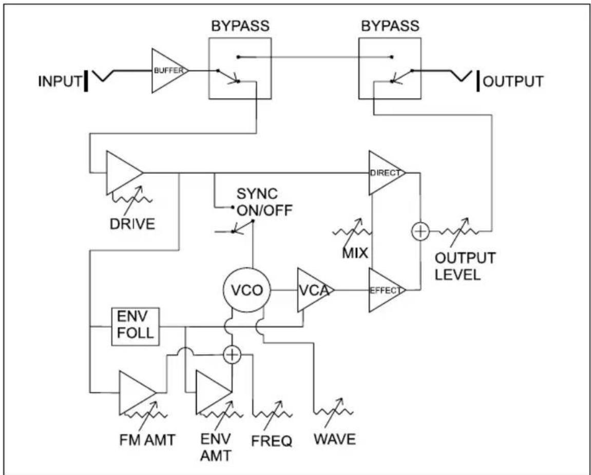
Here is a block diagram of the FreqBox signal and control path:
flowchart
graph TD
    INPUT --> BUFFER
    BUFFER --> BYPASS
    BYPASS --> OUTPUT
    BYPASS --> DIRECT
    DIRECT --> OUTPUT_LEVEL
    OUTPUT --> VCO
    VCO --> VCA
    VCA --> EFFECT
    EFFECT --> OUTPUT_LEVEL
    OUTPUT_LEVEL --> OUTPUT
    VCO --> INV_FOLL
    INV_FOLL --> FM_AMT
    FM_AMT --> ENV_AMT
    ENV_AMT --> FREQ
    FREQ --> WAVE
    WAVE --> VCO
    VCO --> SYNC_ON/OFF
    SYNC_ON/OFF --> DRIVE
    DRIVE --> INPUT
    INPUT --> BYPASS
    BYPASS --> OUTPUT
    OUTPUT --> OUTPUT_LEVEL
    OUTPUT_LEVEL --> OUTPUT_LEVEL
    OUTPUT_LEVEL --> VCO
    VCO --> VCA
    VCA --> EFFECT
Figure 14-Block Diagram of the FreqBox
The input is passed through a unity gain buffer, and then connected to the bypass circuit. In bypass, the buffered input signal is connected directly to the output. In effect active mode, the buffered input signal is passed to the drive circuit. The drive circuit feeds the mix direct VCA, the envelope follower, VCA for the FM input to the VCO, and the sync input to the VCO.
The envelope follower detects the amplitude of the drive output and generates a CV that goes higher as the drive output gets louder. The output of the envelope follower is applied to the control input of the VCA controlling the loudness of the VCO signal, and the input of the VCA for the envelope follower that modulates the VCO frequency. The VCO is a signal source. Its waveform is determined by the Waveform control. The frequency is determined by the Frequency control, the Envelope Follower VCA, and the FM Amount VCA. The VCO signal passes to a VCA with an output controlled by the envelope follower CV so that the amplitude of the VCO signal will follow the amplitude of the direct signal.
The VCO signal is then routed to the mix effect VCA. The Mix control sets the ratio of the direct to effect signals, and the output level control sets the overall output level when the effect is active.
The Front Panel
Bypass Switch: The Bypass switch is a rugged yet smooth acting switch that can be used as a stomp switch or manually activated switch for toggling between bypass mode and effect active mode. When the effect is bypassed, the Bypass LED will be red. Note that the bypass circuit of the FreqBox is a high-quality buffered bypass with unity gain. It will not "suck tone" as do some vintage effects. Also note that the effect circuits are disconnected from the input buffer in bypass, so the Level LED does not indicate the presence of an input signal in bypass mode. This means that the effect's circuits do not load the output of the buffer at all, eliminating any effect that they may have on the bypassed tone. When the effect is active, the Bypass LED should be green, and an input signal is indicated by the Level LED.
Drive: The Drive control is only active when the effect is on (The Bypass LED will be GREEN). It sets the input sensitivity of the MF-107, so that it will work with instrument to line-level inputs. The Drive control can also be turned up for overdriving the input signal. The Level LED is for showing the strength of the output of the drive circuit and can be used as a reference for setting the Drive control. When the Level LED is OFF, then there is no input signal, or it is very low. When the Level LED is Green, it indicates a low-level drive signal is present. When the LED turns yellow-orange, this indicates that the drive signal is at the optimal level. When the LED turns RED, it indicates that the drive signal is beginning to clip.
The Drive signal is also used as the input to the envelope follower and the FM signal for the VCO. This means that the setting of the Drive control has an affect on the response of both the envelope amount control and the FM Amount control, as both rely on the dynamics of your playing. For optimum use of the envelope follower, you'll want to set the Drive control so that your normal signal causes the Level LED to light yellow-orange. A little red is OK for the peaks of your playing. If overdrive is desired, turn the Drive control up until the Level LED is mostly RED. Now the drive signal will no longer be clean. One result of increasing the Drive control is that you also increase the level of the signal available for FM. Another is that the drive signal becomes
compressed and the envelope follower is not as responsive to the dynamics of your playing. It is perfectly OK to use the FreqBox with the Drive control all the way up.
Output Level: The Output Level control is used for balancing the loudness of the signal when the effect is active with the loudness of the signal when the effect is bypassed. When first setting up to play, adjust the drive level first for optimum drive signal level, then adjust the output level so it is balanced with the bypass signal. The Output Level control has a wide enough range to boost the volume significantly - especially with the drive control turned up all the way. Use caution with this control for both your speakers and your ears! The Maximum output level is much greater than your typical stompbox so watch out!!!
Freq: The Freq control is used to adjust the frequency of the VCO. If the Envelope Amount and FM amount controls are all the way counterclockwise, and the Sync is OFF, the Frequency of the VCO is nominally 25Hz if it is fully counterclockwise. When it is fully clockwise the frequency of the VCO is nominally 1.6KHz, or 6 octaves higher.
Wave: The Wave control is used to set the waveform of the VCO. The legend around the control indicates approximately the locations of the waveforms. The basic waveforms are: triangle, sawtooth, square, and pulse. A triangle wave is produced when the control is fully counterclockwise. As the control is advanced clockwise, the waveform is crossfaded to a sawtooth, then to a square wave, then to a pulse wave.
Sync On/Off: The Sync On/Off switch engages the FreqBox's hard sync function, causing the VCO to be retriggered by the input signal. If the input signal has a simple waveform, then the VCO will be retriggered at the frequency of the signal. A very complex signal (like a dissonant chord) will cause less predictable results, as the VCO will be retriggered not at a predictable frequency but by the sum of all the frequencies. A pitched tone may or may not be the result. With guitars, if a note is plucked hard and left to ring, there are times when the second harmonic is louder than the fundamental. You may hear this as the VCO tone will shift with this change. If the VCO frequency is much lower than the input signal, it is possible that you won't be able to hear any output from the VCO, especially if the waveform is a square wave, or pulse wave.
Env. Amount: The Env. Amount control sets the amount that the
envelope follower CV is applied to the VCO frequency. Note that the envelope follower CV is ADDED to the setting of the Freq control. The VCO frequency can be swept by the envelope follower CV over 8 octaves, more than the Freq control on the front panel. Be aware that the setting of the Env. Amount control depends a great deal on the setting of the Drive control, as it is the drive signal that is used to extract the dynamic information. The optimum setting of the drive control is such that average levels cause the Level LED to light mostly Yellow-Orange, and peak levels might cause a little red. If the Drive control is cranked for distortion, then the performance of the envelope follower is reduced in responsiveness as the drive signal is compressed somewhat from the clipping of the signal.
FM Amount: The FM Amount control is used for setting the amount of the drive signal that frequency modulates the VCO. When the FM amount is all the way counterclockwise, none of the drive signal modulates the VCO. As the control is turned clockwise, the amount of FM increases. Note that because the depth of FM is also related to the strength of the drive signal, that the Drive control and the dynamics of the input signal affect the depth of the FM. For a stronger maximum FM effect, increase the Drive amount. The type of input signal has a significant impact on the output when using FM. The simpler the input signal's waveform, the more predictable the results will be. A more complex input creates more sidebands and thus a more chaotic sound. The waveform of the VCO also has a great deal to do with the results, as the brighter waveforms (saw, square, and pulse) create a lot of harmonics.
Mix: The Mix control sets the balance of drive signal to VCO signal. When the Mix control is fully counterclockwise, the output is 100% the input signal. When the Mix control is in the center the output is 50% input signal and 50% VCO signal. When the Mix control is all the way clockwise, the output is 100% the VCO signal.
The Back Panel
Audio connections: The Audio In and Audio Out Jacks are standard 14 " unbalanced connections. Connect your instrument or signal to the Audio In and connect the Audio Out to your amplifier or mixer.
CV/Expression Inputs: There are five standard 14 " inputs for control
voltages or expression pedals corresponding to the five controls: Freq, Wave, Env. Amount, FM Amount, and Mix. All of these inputs accept an expression pedal like the Moog EP1 or EP2 with tip-ring-sleeve plugs, or a CV on standard tip-sleeve cables. All inputs are added to the setting of the front panel controls. With expression pedals plugged in, set the panel control to the lowest setting you want with the pedal in heel position, then when you advance the pedal, it increases that parameter, just as if you were turning the control on the front panel clockwise. The following are the details of each input's behavior with control voltages:
- Freq CV In accepts a -5 to +5 CV signal, and is calibrated for the VCO to change one octave for very volt change at the input. The control input extends the frequency range of the VCO well beyond the 25Hz-1.6KHz range of the front panel Frequency control. The VCO oscillates from sub-audio up to 20KHz.
- Wave CV In accepts a zero to +5V CV signal. The range of effect from a zero to +5V CV is 60% of the range of the front panel control.
- Env. Amount CV In accepts a zero to +5V CV signal. The range of effect from a zero to +5V CV is 100% of the range of the front panel control.
- FM Amount CV In accepts a zero to +5V CV signal. The range of effect from a zero to +5V CV is 100% of the range of the front panel control.
- Mix CV In accepts a zero to +5V CV signal. The range of effect from a zero to +5V CV is 100% of the range of the front panel control.
CV Outputs: The FreqBox has two CV outputs which can be used to modulate other Voltage controlled gear, such as Moogerfooger analog effects, the Minimoog Voyager analog synthesizer or Little Phatty analog synthesizer. The following are the details of these outputs:
- Env. Follower CV Out: This is the unfiltered Envelope Follower CV, which is generated from the Drive signal. The Envelope Follower CV is only produced when the effect is active and a signal is present at the audio input. The level is nominally zero to +5V. This signal carries larger audio-induced ripple than the signal used for modulating the VCO, or the VCO's VCA.
- Oscillator Direct CV Out: This is the direct output of the VCO's waveshaping circuit before it goes to the VCA, so this signal is always present, and is nominally +/-2.5V . That's a lot stronger than an instrument level signal, so we don't recommend plugging this output into an instrument amplifier.
ADVANCED APPLICATIONS
Using w/ other effects
The FreqBox is a natural for using with other effects. It is the perfect type of signal to run into a filter, because it can produce the basic waveforms used for subtractive synthesis. Filter effects include the MF-101 Lowpass Filter, the MF-103 12-Stage Phaser, and the MF-105 MuRF (Multiple Resonant Filter Array). A MF-104 Analog Delay is also a good choice, as it has some really nice filter characteristics and delay can really fatten up the VCO sound. If you find the FreqBox to be too dynamically sensitive for your style of playing, or too dynamically sensitive to your instrument, try putting a distortion device or compressor before the FreqBox.
This will have the effect of compressing the FreqBox VCO as well as providing more sustain.
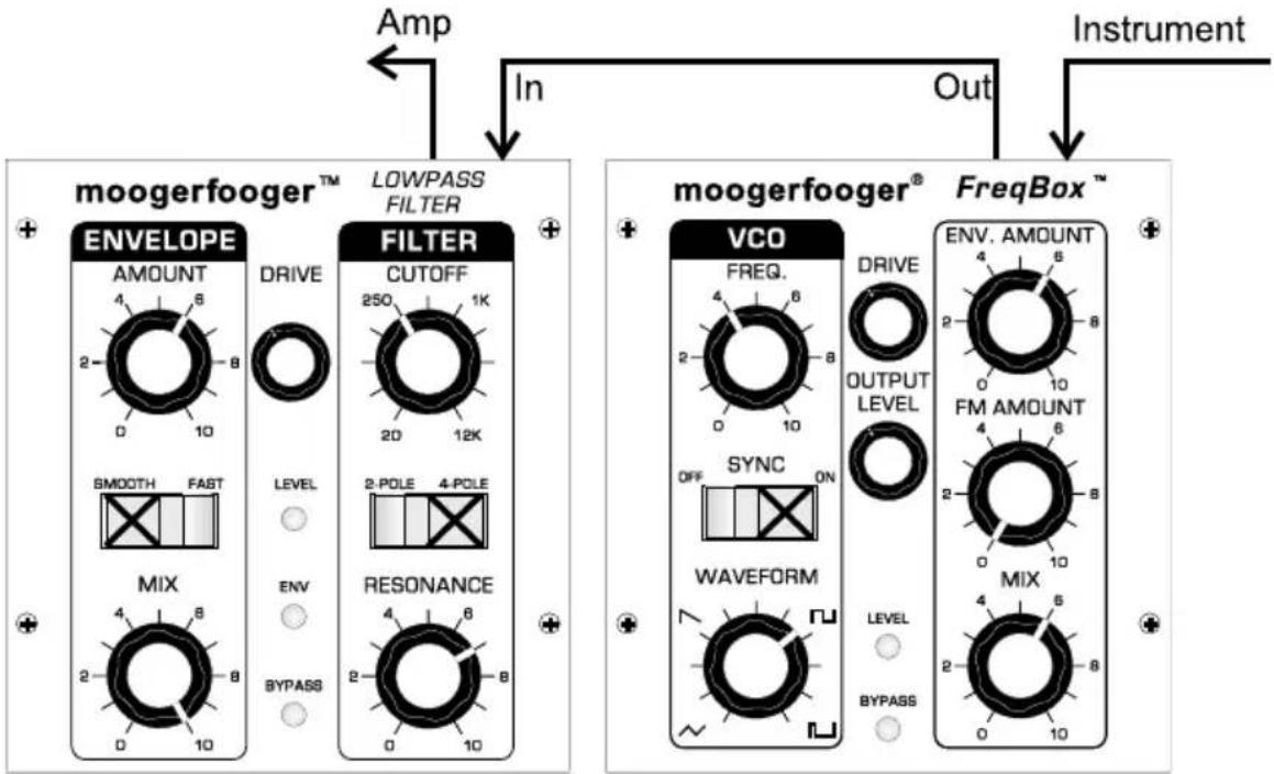
Using the FreqBox with a MF-101 Lowpass Filter
Envelope SyncFilter.
flowchart
graph TD
    A["Amp"] --> B["In"]
    B --> C["Instrument"]
    D["moogerfooger™ LOWPASS FILTER"] --> E["IN"]
    E --> F["Out"]
    G["moogerfooger® FreqBox™"] --> H["In"]
    H --> I["Instrument"]
    J["ENVELOPE"] --> K["AMOUNT 4 8 2 10"]
    J --> L["DRIVE 250 1K 20 12K"]
    M["FILTER"] --> N["CUTOFF 2POLE 4POLE 2 POLE 4POLE"]
    O["MIX"] --> P["ENV 4 8 2 8 10"]
    Q["BYPASS"] --> R["RESONANCE 4 6 2 8 0 10"]
    S["VCO"] --> T["FREQ. 4 6 2 8 0 10"]
    U["SYNC"] --> V["OFFSET ON"]
    W["WAVEFORM"] --> X["LEVEL 2 6 8 0 10"]
    Y["BYPASS"] --> Z["LEVEL 2 6 8 0 10"]
Figure 15 - Envelope Sync Filter
This setup uses a FreqBox and a MF-101 Lowpass Filter.. This setup is the same as the AutoSyncSweep on the FreqBox, with the MF-101 also setup to respond to your playing dynamics with its own envelope follower. This is a really fun and funky sound to play with if you have a sound with a sharp attack and quick decay like a plucked guitar string.
Using the FreqBox with a CP-251 Control Processor
Sample and Hold Sync
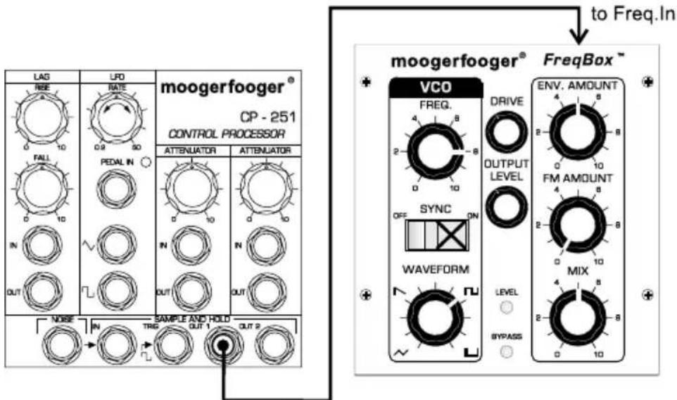
Figure 16 - Sample and Hold Sync
This setup patches the Sample and Hold output of the CP-251 to the Frequency input. The setup is pretty much otherwise the Basic Sync Setup. It illustrates the use of CVs to modulate the FreqBox parameters. This one is pretty nice for pseudo-arpeggiated sparkly sounds. You can easily substitute other time-varying CVs such as the LFO triangle wave for further exploration of this idea.
PWM
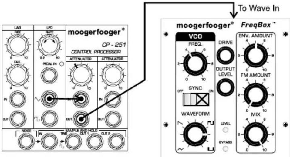
Figure 17 - PWM
This setup uses the LFO triangle wave from the CP-251 to modulate the waveform of the VCO, which is set halfway between square and the pulse setting. The trick is to adjust the attenuator for the right LFO amount such that the sound seems "fatter and skinnier" in time with the LFO. This is varying the pulse width of the VCO waveform and is called
pulse-width modulation or PWM. The rest of this setup is the basic sync setup, the PWM adds a cool shifting, swirling sound to the VCO.
W/ Voyager/VX-351
Many folks will want to use the FreqBox as an extra oscillator in their analog setup, such as a Voyager with the VX-351 CV Expander. The Freq control input is set at the factory to change the VCO frequency one octave per volt change at the input (commonly called 1V/Octave). This means a 1V/Oct signal generated by a keyboard would allow the keyboard to control the frequency of the VCO. Figure 18 shows a diagram of such a setup. Set the External Audio In switch of the Voyager's Mixer to ON, and turn the External Audio level up to mix the FreqBox VCO signal with the Voyager oscillators. Tune the FreqBox VCO frequency in relation to the Voyager's Oscillator 1.
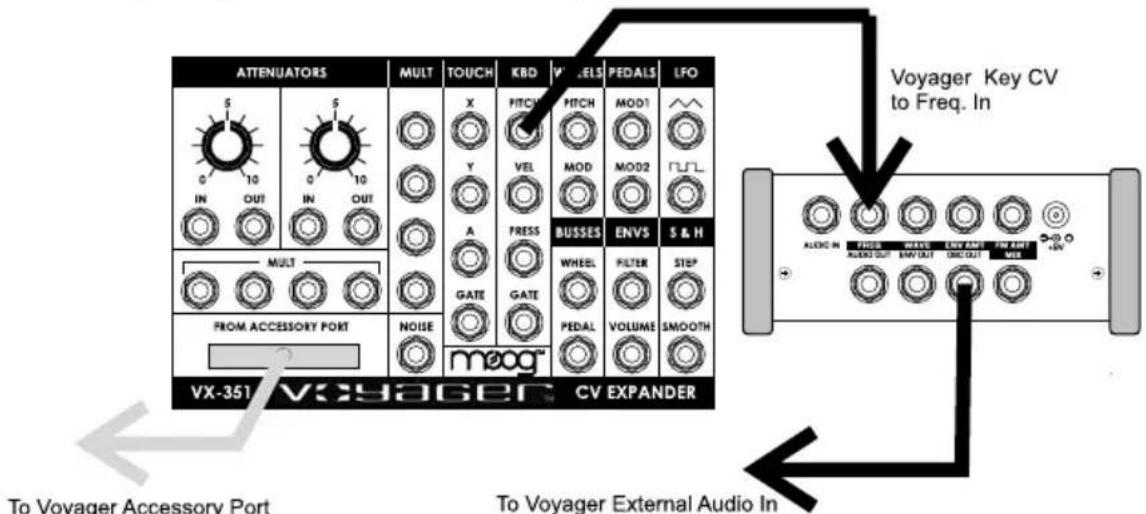
Figure 18 - Using the FreqBox with a Voyager/VX-351
There are some technical considerations for using the FreqBox for this and similar applications. First, the FreqBox VCO is a descendant of the Voyager VCO, but is not exactly the same. It will not have exactly the same sound. Second, FreqBox VCO is subject to oscillator drift with temperature change. In many situations, such as studio settings where the temperature doesn’t vary, the FreqBox will be tuning stable, but in situations where the temperature can change drastically, you may find that the FreqBox VCO drifts somewhat in frequency. Finally, the linearity of the FreqBox CV response is good in the lower and mid-range frequencies, but may not be perfectly linear at higher frequencies. These considerations aside, a wide range of musical usage is available to the analog musician using the FreqBox as an oscillator in a voltage controlled system.
TECHNICAL INFORMATION
NOTE: The following information is intended for use by people who understand analog electronic circuitry and have enough practical experience to interconnect sophisticated electronic equipment correctly.
POWER: The MF-107 works on +9 volts DC and uses a max of about 200 milliamperes of current. Use only the power supply supplied with the MF-107 or the exact equivalent. Power sources rated with voltages in excess of +9 volts may cause damage to the MF-107's circuits, and will void the warranty.
PEDAL INPUTS: All pedal control input jacks are 1/4" tip-ring-sleeve (stereo) phone jacks. The sleeves are grounded and the ring terminals are supplied with +5 volts which is current-limited. The tip terminals receive the variable voltages from the pedals.
An expression pedal for use with the MF-107 should contain a 50KOhm or 100KOhm linear taper potentiometer which is connected from the sleeve to the ring terminals. The potentiometer wiper is connected to the tip terminal. The pedal cable should be shielded, with the shield connected to the sleeve terminal.
With the MF-107, You can use any combination of expression pedals and cables that carry CVs. Regular tip-sleeve cables work fine with each input, as there is a separate current limiting circuit for each control input - so you won't burn anything out. Applying a varying voltage to the tip terminal of a pedal control input jack has the same effect as turning the corresponding knob. Note the voltages here are summed with the voltages from the front panel controls. You set the minimum voltage with the front panel controls. The Freq. In is the only control that accepts a negative input, as it can accept a -5V to +5V Input. All other control inputs are designed to accept zero to +5V inputs. Do not exceed these ratings.
LIMITED WARRANTY
Moog Music warrants that its products will be free from defects in materials or workmanship, and shall conform to specifications current at the time of shipment, for a period of one year from date of purchase. During the one-year period, any defective products will be repaired or replaced, at Moog Music's option, on a return-to-factory basis. This Warranty covers defects that Moog Music determines are no fault of the user.
RETURNING YOUR MF-107 FOR REPLACEMENT/REPAIR
You must obtain prior approval and an RMA number from Moog Music before returning any product to us. Wrap your MF-105 carefully and pack it with the power adaptor in its original carton. The warranty will not be honored if the product is not properly packed. Then send it to Moog Music with transportation and insurance charges paid.
A reasonable cost for service and for materials and return freight will be charged to replace materials defective through the fault of the user, or for which the one year warranty period has expired.
Transportation and insurance charges from Moog Music to your United States address, of products repaired or replaced under warranty, will be paid by Moog Music.
MF-107 SPECIFICATIONS
DESCRIPTION:
Analog effects module containing a VCO with continuously variable waveform which can be hard synced and/or Frequency modulated by the input signal and an Envelope Follower that can modulate the VCO frequency.
FRONT PANEL FEATURES:
DRIVE rotary control - adjusts the gain of the audio input to the effect. OUTPUT LEVEL rotary control - balances the level of the FreqBox's signal when the effect is on with the bypassed signal when the effect is off.
MIX rotary control - adjusts the ratio of direct to effected signal when the effect is on.
FREQUENCY rotary control - sets the VCO frequency from 25Hz-1.6KHz
WAVEFORM rotary control - varies the VCO waveform continuously from triangle to sawtooth to square to pulse.
ENVELOPE AMOUNT rotary control - adjusts the amount of envelope follower CV modulating the VCO frequency
FM AMOUNT rotary control - adjusts the amount of input signal to frequency modulate the VCO
LEVEL, a three-color LED that shows the level of the input signal.
BYPASS, a two-color indicator LED that tells whether the effect is active or bypassed.
ON/BYPASS, a rugged, smooth-acting ‘stomp switch’.
REAR PANEL FEATURES:
AUDIO IN 14 " phone jack – accepts any instrument-level or line-level signal from -16 dBm to +4 dBm. Input impedance is 1 Megohm.
AUDIO OUT 14 " phone jack - -4 dBm nominal maximum output level; +10dBm absolute maximum output level. Output impedance is 1KOhms. FREQ, WAVE, ENV.AMT, FM AMT, MIX, all of which are stereo 14 " jacks that accept moogerfooger EP1 (or equivalent) expression pedals, or control voltages from two-circuit or three-circuit 14 " jacks.
ENV.OUT CV output carries the unfiltered Envelope Follower CV generated by the MF-107's envelope follower. Nominal output ranges from 0 to +5 Volts. This output only available when effect is ON OSC. OUT CV output carries the VCO direct signal. The nominal output level is 5 volts peak-to-peak.
+9V POWER INPUT jack – accepts +9VDC unregulated 300 mA power adapter with positive center.
GENERAL SPECIFICATIONS:
CASE: Black panel with hardwood sides – classic analog appearance.
DIMENSIONS: 9" x 6" x 2-1/2"
NET WEIGHT: 2 lb
SHIPPING WEIGHT: 4 lb, including power adaptor and instruction manual
POWER REQUIREMENTS: 120 volt, 5W. 220 volt power adaptor available on special order
MOOG MUSIC Inc. 2004E RIVERSIDE DRIVE ASHEVILLE, NC 28804
Phone: (828) 251 0090 FAX: (828) 254 6233
Email: info@moogmusic.com
WEB SITE: http://www.moogmusic.com
©2007 Moog Music Inc.
Notes:
- Understanding and Using your
- moogerfooger®
- MF-107 FreqBox TM
- TABLE OF CONTENTS
- The Story Behind the FreqBox
- GETTING STARTED RIGHT AWAY!
- 7) READ THE MANUAL TO FULLY UNDERSTAND THIS
- BASIC APPLICATIONS
- Basic Sync Setup:
- Sync+FM
- AutoSyncSweep
- Drone
- Foot Theremin
- FM Gongs
- FM sizzler
- Electro Drumz
- FREQBOX THEORY
- Fundamentals of sound
- VCOs
- VCO Waveforms
- Hard Sync
- FM
- VCA
- Envelope Follower
- FREQBOX FUNCTIONS
- The Front Panel
- The Back Panel
- ADVANCED APPLICATIONS
- Using w/ other effects
- Using the FreqBox with a MF-101 Lowpass Filter
- Envelope SyncFilter.
- Using the FreqBox with a CP-251 Control Processor
- Sample and Hold Sync
- PWM
- W/ Voyager/VX-351
- TECHNICAL INFORMATION
- LIMITED WARRANTY
- RETURNING YOUR MF-107 FOR REPLACEMENT/REPAIR
- MF-107 SPECIFICATIONS
- DESCRIPTION:
- FRONT PANEL FEATURES:
- REAR PANEL FEATURES:
Brand : Moog
Model : Freqbox MF-107
Category : Uncategorized