
SS560FK - TV Stand Peerless-AV - Free user manual and instructions
Find the device manual for free SS560FK Peerless-AV in PDF.


| Brand | Peerless-AV |
| Model | SS560FK |
| Product Type | TV Stand |
| Maximum Display Load Capacity | 150 lb (68 kg) |
| Maximum Component Load Capacity | 15 lb (6.8 kg) |
| Tilt Adjustment | 0° or 30° |
| Cable Management | Yes, through column |
| Suitable For | Institutional use |
| Installation Tools Required | Phillips screwdriver and included allen wrenches |
| Included Tools | 6 mm, 7/32", 3/16", 4 mm allen wrenches; penta-pin tool; security allen wrench |
| Security Feature | Security screws to lock display |
| Warranty | Limited Five-Year |
| Material | Steel |
| Color | Black |
| Assembly Required | Yes |
| Compatibility | Flat panel displays with VESA mounting holes |
| Parts Included | Base, column, column bracket, tilt plate, adapter plate, adapter brackets, top/bottom plates, rubber feet, fasteners |
| Maximum Torque for Screws | 40 in·lb (4.5 N·m) |
Frequently Asked Questions - SS560FK Peerless-AV
User questions about SS560FK Peerless-AV
0 question about this device. Answer the ones you know or ask your own.
Ask a new question about this device
Download the instructions for your TV Stand in PDF format for free! Find your manual SS560FK - Peerless-AV and take your electronic device back in hand. On this page are published all the documents necessary for the use of your device. SS560FK by Peerless-AV.
USER MANUAL SS560FK Peerless-AV
Suitable For Institutional Use

natural_image
Technical line drawing of a mechanical support structure with mounting base (no text or symbols)
Max UL Load Capacity:
150 lb (68 kg) display
15 lb (6.8 kg) component
NOTE: Read entire instruction sheet before you start installation and assembly.
WARNING
- Do not begin to install your Peerless product until you have read and understood the instructions and warnings contained in this Installation Sheet. If you have any questions regarding any of the instructions or warnings, for US customers please call Peerless customer care at 1-800-865-2112, for all international customers, please contact your local distributor.
- This product should only be installed by someone of good mechanical aptitude, and fully understands these instructions.
- Never exceed the Maximum UL Load Capacity on page 1. Use with heavier televisions may result in instability causing tip over resulting in death or serious injury.
• Always use an assistant or mechanical lifting equipment to safely lift and position equipment. - Tighten screws firmly, but do not overtighten. Overtightening can damage the items, greatly reducing their holding power.
- The cart or stand is not affixed or secured to the floor, and may therefore tip over and/or fall if screen and/or stand is shaken or hit. Not recommended for use in areas with heavy traffic.
- Death or serious injury may occur when children climb on audio and/or video equipment furniture. A remote control or toys placed on the furnishing may encourage a child to climb on the furnishing resulting in the furnishing tipping over on to the child.
- Relocating audio and/or video equipment from this cart or stand to furniture not specifically designed to support audio and/or video equipment may result in death or serious injury due to the furnishing collapsing or over turning onto a child.
- This product is intended for indoor use only. Use of this product outdoors could lead to product failure and personal injury.
Tools Needed for Assembly
- phillips screwdriver
Table of Contents
| Parts List | 3, 4 |
| Assembling Stand | 5 |
| Installing Adapter Brackets to Flat Panel Display | 7 |
| Mounting Flat Panel Display | 9 |
| Cable Management | 9 |
Before you begin, make sure all parts shown are included with your product.
| Parts List | ||
| Description Qty. Part Number | ||
| A | base 1 009-1425 | |
| B | column 1 009-1426 | |
| C | column bracket 1 009-1424 | |
| D | tilt plate 1 009-1423 | |
| E | adapter plate 1 201-1110 | |
| F | adapter bracket 2 202-1655 | |
| H | 3/8-16 x 1" button socket cap screw 3 | 520-1354 |
| I | 5/16"-18 x 3/8" button socket cap screw 4 | 520-1693 |
| J | M10 lock washer 3 | 540-9424 |
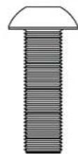
| K | M10 x 15 mm button socket cap screw 4 | 520-9262 |
| L | 3/8-16 X 2-1/2" button socket cap screw 3 520-9550 | |
| M | 6 mm allen wrench | 1 560-9716 |
| N | 7/32" allen wrench | 1 560-9715 |
| O | 3/16" allen wrench 1 560-0071 | |
| P | top plate | 1 201-1724 |
| Q | bottom plate | 1 201-1699 |
| R | rubber feet (pack of four) | 1 570-1036 |
| S | M8 x 15mm socket pin screw | 4 520-1068 |
| T | M10 x 15mm penta-pin screw | 4 520-9263 |
| U | M10 penta-pin tool | 1 520-9260 |
| V | 4mm allen wrench | 1 560-9646 |
Parts may appear slightly different than illustrated.


natural_image
Technical line drawing of a mechanical housing or enclosure with internal components and mounting holes (no text or symbols)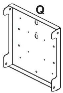
natural_image
Isometric line drawing of a rectangular metal frame with holes and a labeled point Q (no text or symbols beyond the label)R

S
T


natural_image
Line drawing of a cylindrical mechanical part with a flanged end and a labeled section U (no text or symbols on the object itself)
natural_image
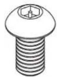
Simple line drawing of a bent pipe or rod with label 'V' (no other text or symbols)Security Adapter Bracket Fasteners


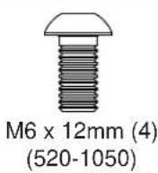
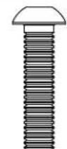


Multi-washer (4)
(580-1398)
M5 x 25mm (4)
(520-1122)
M6 x 25mm (4)
(520-1211)
M8 x 25mm (4)
(520-1101)
1 Attach column (B) to base (A) with three 3/8-16 x 2-1/2" button socket cap screws (L) and three M10 lock washers (J). Tighten screws using 7/32" allen wrench (N).

2 Attach the column bracket (C) to column (B) with three 3/8-16 x 1" button socket cap screws (H). Tighten screws using 7/32" allen wrench (N).

3 Attach tilt plate (D) to bottom plate (Q) with four M10 x 15 mm button socket cap screws (K). Tighten screws using 6 mm allen wrench (M).
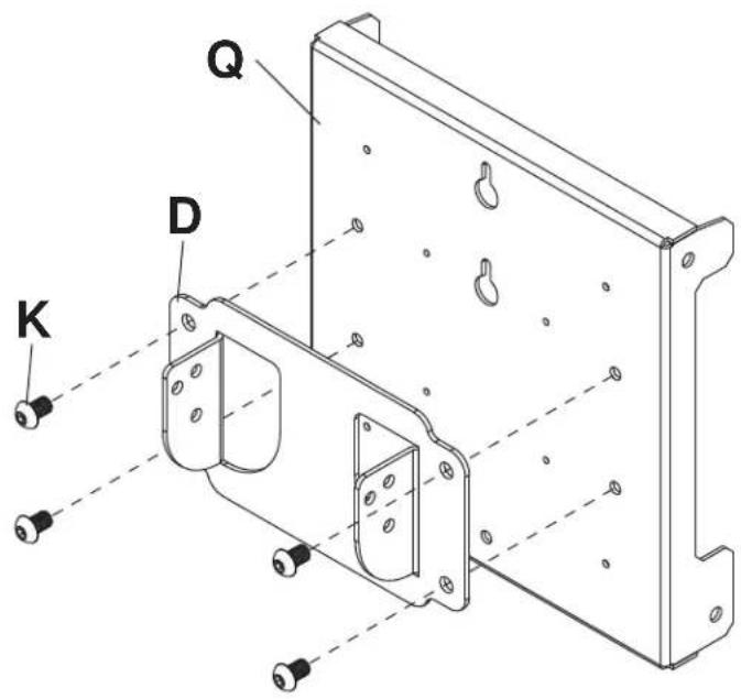
4 Attach tilt plate (D) to column bracket (C) with four 5/16-18 x 3/8" button socket cap screws (I) as shown in rear view. Tilt can be adjusted to 0° or 30°.

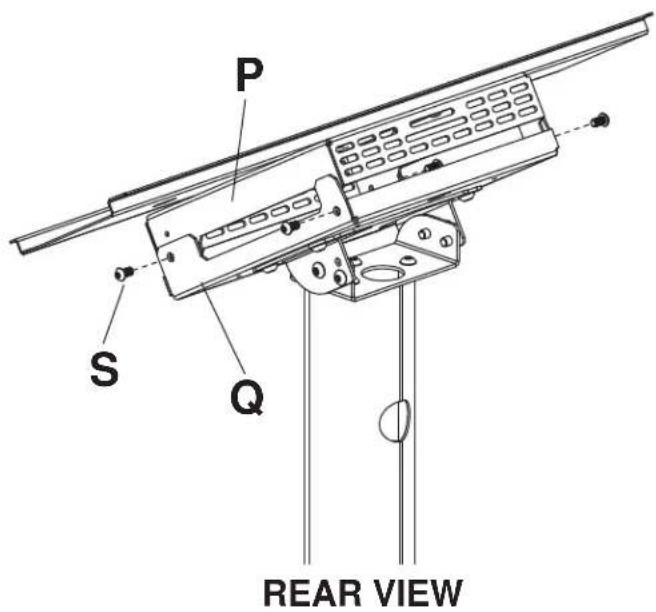
REAR VIEW
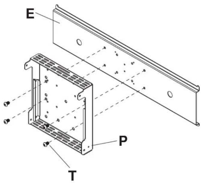
5 Attach top plate (P) to adapter plate (E) with four M10 x 15 mm penta-pin screws (T).
Tighten screws using penta-pin tool (U).
6 Secure four rubber feet (R) to bottom of CPU as shown below.

6-1 Secure CPU to top plate (P) using safety belt. NOTE: Safety belt may need to be loosened to attach CPU to component box top plate.

7 Secure top plate (P) to bottom plate (Q) with four M8 x 15 mm screws (S) as shown in rear view. Tighten screws using 4 mm allen wrench (V).
Installing Adapter Brackets to Flat Panel Display
WARNING
- Tighten screws so adapter brackets are firmly attached. Do not tighten with excessive force. Overtightening can cause stress damage to screws, greatly reducing their holding power and possibly causing screw heads to become detached. Tighten to 40 in. • Ib (4.5 N.M.) maximum torque.
- If screws don't get three complete turns in the display inserts or if screws bottom out and adapter brackets are still not tightly secured, damage may oXur to display or product may fail.

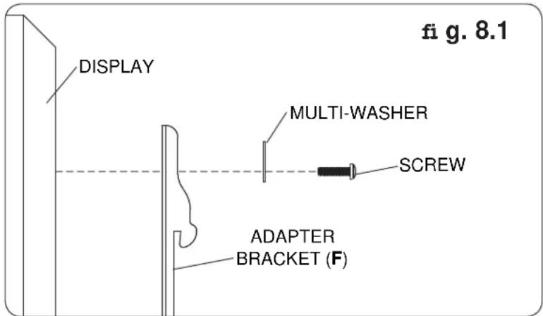
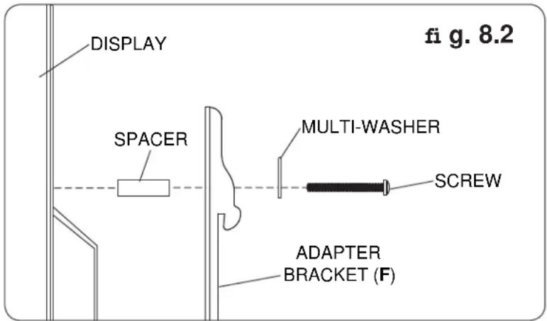
To prevent scratching the display, set a cloth on a flat, level surface that will support the weight of the display. Place display face side down. Refer to display manufacturers instructions or customer service, for removing any knobs, base, cover, or screw(s) on the back of the display to prepare mounting. These need to be removed to allow the adapter brackets (F) to be attached. Select the small, medium, large or extra large screws from the baffled fastener pack then attach adapter brackets to display following figure 8.1 or 8.2.
NOTE: Top and bottom mounting holes must be used for attaching adapter brackets. Verify that all holes are properly aligned, and then tighten screws using 4 mm security allen wrench (BB).
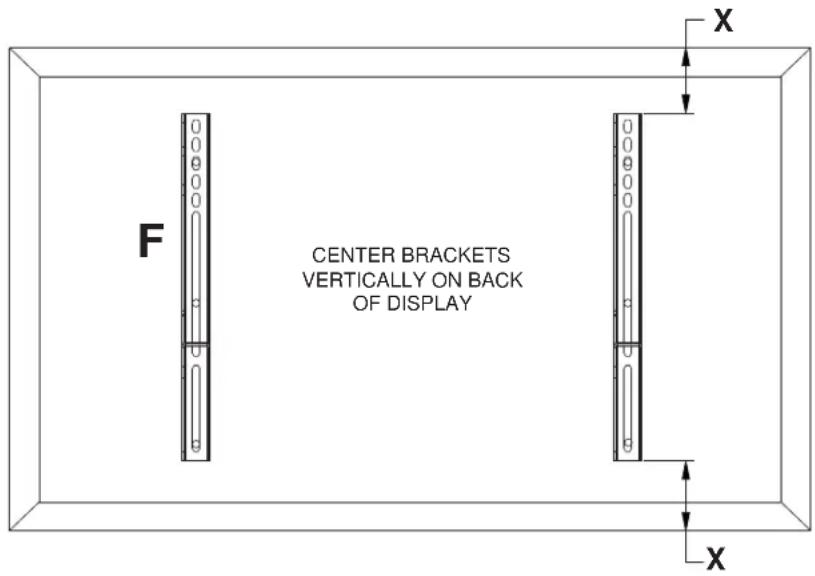
NOTE: "X" dimensions should be equal.
Notes:
- The number of fasteners used will vary, depending upon the type of display.
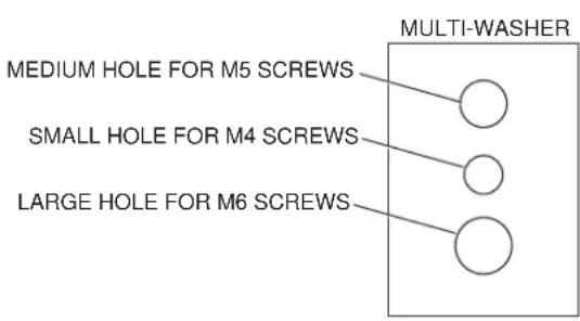
- Multi-washers and spacers may not be used, depending upon the type of display.
- Use the corresponding hole in the multi-washer that matches your screw size as shown.
NOTE: For flat back displays proceed to step 8-1. For bump-out or recessed back display skip to step 8-2.
For Flat Back Display
8-1
Begin with the shortest length screw, hand thread through multi-washer and adapter bracket into display as shown below. Screw must make at least three full turns into the mounting hole and fit snug into place. Do not over tighten. If screw cannot make three full turns into the display, select a longer length screw from the baffled fastener pack. Repeat for remaining mounting holes, level brackets and tighten screws.
NOTE: Spacers may not be used, depending upon the type of display.
If you have any questions, please call Peerless customer care at 1-800-865-2112.
For Bump-out or Recessed Back Display
8-2
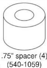
Begin with longer length screw, hand thread through multi-washer, adapter bracket and spacer in that order into display as shown below. Screw must make at least three full turns into the mounting hole and fit snug into place. Do not over tighten. If screw cannot make three full turns into the display, select a longer length screw from the baffled fastener pack. Repeat for remaining mounting holes, level brackets and tighten screws.
If you have any questions, please call Peerless customer care at 1-800-865-2112.
Mounting Flat Panel Display

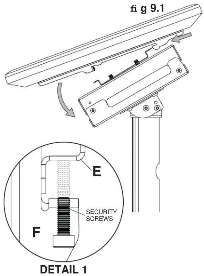
Hook adapter brackets (F) onto adapter plate (E). Then slowly swing display down as shown. Turn security screws, using 4 mm security allen wrench (V), clockwise at least six times to prevent display from being removed as shown in detail 1 of figure 9.1.
NOTE: To lock the display down, tighten security screws to adapter plate (E) as shown in detail 1.
Cable Management

Run cables through column (B) using cable management holes.

Service and Maintenance

This product has no user serviceable parts.
LIMITED FIVE-YEAR WARRANTY
Peerless Industries, Inc. ("Peerless") warrants to original end-users of Peerless® products will be free from defects in material and workmanship, under normal use, for a period of five years from the date of purchase by the original end-user (but in no case longer than six years after the date of the product's manufacture). At its option, Peerless will repair or replace, or refund the purchase price of, any product which fails to conform with this warranty.
In no event shall the duration of any implied warranty of merchantability or fitness for a particular purpose be longer than the period of the applicable express warranty set forth above. Some states do not allow limitations on how long an implied warranty lasts, so the above limitation may not apply to you.
This warranty does not cover damage caused by (a) service or repairs by the customer or a person who is not authorized for such service or repairs by Peerless, (b) the failure to utilize proper packing when returning the product, (c) incorrect installation or the failure to follow Peerless' instructions or warnings when installing, using or storing the product, or (d) misuse or aXident, in transit or otherwise, including in cases of third party actions and force majeure.
In no event shall Peerless be liable for incidental or consequential damages or damages arising from the theft of any product, whether or not secured by a security device which may be included with the Peerless® product. Some states do not allow the exclusion or limitation of incidental or consequential damages, so the above limitation or exclusion may not apply to you.
This warranty is in lieu of all other warranties, expressed or implied, and is the sole remedy with respect to product defects. No dealer, distributor, installer or other person is authorized to modify or extend this Limited Warranty or impose any obligation on Peerless in connection with the sale of any Peerless® product.
This warranty gives specific legal rights, and you may also have other rights which vary from state to state.

www.peerless-av.com
© 2014 Peerless Industries, Inc.


Brand : Peerless-AV
Model : SS560FK
Category : TV Stand