
CA532 - Laser pointer Picotronic - Free user manual and instructions
Find the device manual for free CA532 Picotronic in PDF.


| Product Type | Laser Module (Line/Cross Projection) |
| Brand | Picotronic |
| Model | CA532 |
| Series | 40x210 Series |
| Laser Class | Class 2M (per DIN EN 60825-1:2008-05) |
| Wavelength | 532 nm (green) |
| Output Power | ≤ 50 mW (nominal) |
| Power Supply | 230 V AC (50 Hz) with European standard connector or 24 V DC via pluggable adapter |
| Connection Type | AC: CEE 7/7 plug; DC: tinned ends for stabilized source |
| Projection Type | Laser line (L Series) or laser cross (C Series) |
| Dimensions (Approx.) | 22 mm (diameter) x 210 mm (length) |
| Weight (Approx.) | 200 g |
| Housing Material | Aluminum |
| Mounting | 22 mm shaft bracket with 360° rotation capability |
| Intended Use | Alignment and positioning of workpieces (e.g., saw blade alignment) |
| Safety Features | Warning label, natural blink reflex protection (Class 2M) |
| Maintenance | Clean lens with soft cloth and glass cleaner; no user-serviceable parts |
| Service | Contact Picotronic or authorized service center for repairs |
Frequently Asked Questions - CA532 Picotronic
User questions about CA532 Picotronic
0 question about this device. Answer the ones you know or ask your own.
Ask a new question about this device
Download the instructions for your Laser pointer in PDF format for free! Find your manual CA532 - Picotronic and take your electronic device back in hand. On this page are published all the documents necessary for the use of your device. CA532 by Picotronic.
USER MANUAL CA532 Picotronic
natural_image
Close-up of wooden slats with a yellow tool cutting through, no visible text or symbols
natural_image
Close-up of a metallic optical instrument with green laser beam and red laser lines, no visible text or symbolsnatural_image
Abstract blue background with a vertical light blue shape on the left (no text or symbols)Vorwort
natural_image
Diagram showing two red laser beams interacting with a gray base, with a green checkmark indicating the right-hand side (no text or symbols present)Abbildung 2

natural_image
Diagram showing a red laser beam interacting with a gray base, marked with a red X (no text or symbols present)4. Inbetriebnahme
These operating instructions are an integral part of your product and contain important notes on risk-free operation of your laser module. Please observe these instructions at all times in order to avoid danger, repair costs and downtime.
The device was designed and built to reflect the current state of the art and put through exhaustive functional tests before delivery. Despite this, risks for the user or impairment of the device cannot be ruled out in case of unintended use.
- Please read the operating instructions carefully before commissioning the laser module.
- The laser module operator must have access to the operating instructions at the place of use at all times.
If you have any questions on operating your laser module, please do not hesitate to contact us by phone or in writing:
Picotronic GmbH
Our laser products are tested in line with DIN EN 60825-1 2008:5 and assigned to a laser class.
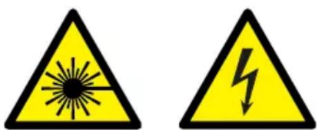
The laser class is stated on the warning label attached to the device.
The precautions for operating this laser module depend on the laser class.
During operation, accident prevention regulations such as BGV B2 and OStrV, or local equivalents, must be observed. The operator is responsible for complying with legal requirements for operating the laser module.
For more safety instructions, please visit:
http://www.picotronic.de/safety
1.1 Laser classes
| Laser class 1 Accessible laser radiation is harmless. | |
| Laser class 1M | The accessible laser radiation is harmless providing no optical instruments such as magnifying glasses or binoculars are used. |
| Laser class 2 | The accessible laser radiation is only in the visible spectral range (400 nm to 700 nm). It is also safe for the human eye in case of short term exposure to radiation (up to 0.25 s). A longer exposure is prevented by the natural eyelid closing reflex. |
| Laser class 2M | Like class 2 providing no optical instruments such as magnifying glasses or binoculars are used. |
| Laser class 3R The accessible laser radiation is dangerous to the human eye. | |
| Laser class 3B | The accessible laser radiation is dangerous to the human eye and in special cases also to the skin. |
| Laser class 4 | The accessible laser radiation is dangerous to the human eye and dangerous to the skin. Diffuse radiation can also be dangerous. The laser radiation can cause a danger of fire or explosion. |
1.2 Warning label

1.3 Safety instructions for electronic connections
| With pluggable power adapter With mains connector | |
| Please use only the power adapter supplied. | The product is equipped with a power cable of the type H05VV-F and the connecting plug of the type AC CEE 7/7. The connecting cable is designed for moderate mechanical stress. |

- Connecting cables must be checked for damage prior to starting up.
- The warranty will be voided if you remove the mains connector
1.3 Safety instructions for damage and operation

- If the housing or lens of the laser module are damaged, this can - under certain circumstances - result in laser radiation of a higher class being emitted that is hazardous to your eyes.
- Do not switch the device on if the housing, lens or power supply are damaged.
- Please note that looking into the laser beam can cause dazzling and that the operating state of machines such as rotating saws cannot be unambiguously identified.
• Never operate the laser module in an area with a risk of explosion.
• Never modify the laser module.
1.4 Risk assessment
Note that the output stated on the type plate reflects the nominal output of the laser beam source.
However, the risk that emanates from a laser depends on the output of the device or the maximum possible means strength at a distance of 70 mm or 100 mm from the beam source. Thus, the hazard presented by our line or crosshair lens laser modules of the laser class 3R is equivalent to that of class 2 or 1 laser just a few centimetres behind the permissible measuring distance.
As the manufacturer, we are obliged to classify our devices to reflect their maximum output or radiation level. The operator can, however, install safety equipment that reflects the actual risk occurring at the place of use. For example, if the laser is mounted at an inaccessible height, the risk that emanates from our laser modules with line or crosshair lens is far lower than the typical risk for the stated laser class. On site, these differences can easily be determined by measuring the maximum accessible beam.
Following installation and commissioning, the complete system can often be assigned to a lower risk class than the laser itself.
2. Intended use
This laser module supports the projection of a laser line (L Series) or laser cross (C Series). The laser is suitable for aligning and positioning workpieces. The operator is responsible for ensuring intended use.
The device must be used by qualified, authorised and trained staff only. Any person wor-
king on or with the device must have read and understood these operating instructions. The laser module operator must have access to the operating instructions at the place of use at all times.
3. Installation
Our laser modules are delivered in ready-to-install state. For commissioning, the device only needs to be connected to the electrical power supply and adjusted to match the machine's cutting line.
Under normal circumstances, the laser is delivered pre-adjusted in the bracket.
40x210 Series laser modules Base plate


3.1 Installing the 40x210 series:
If you do make any changes to the laser's position yourself, please follow these steps:
Step 1:
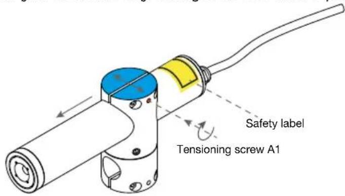
Using clamp screw A1, open up the bracket so that the laser slots into it easily. Use a 2.5 mm Allen key. Make sure that the labels are not damaged.

Step 2:
After slotting in the laser module, release clamp screw A1. The two jaws should now hold the laser loosely.

Step 3:
Now secure the laser with the two fastening screws B1. Use a 4 mm Allen key. Hand tightening is sufficient.

Step 4:
You can attach the laser to a 22 mm shaft, or use our base plate. Proceed as per steps 1 to 3. The entire bracket can be tilted via the 22 mm shaft.

Step 5:
You can rotate the entire laser bracket through 360°. To do so, use a 4 mm Allen key to release the three fastening screws C1. Make sure that the cable is not kinked or stressed due to the rotation.

- During installation, make sure that the bracket is securely anchored.
- Check the threaded joints regularly.
- Check the alignment of the laser module.
3.2 Installation on the machine
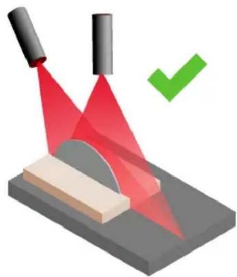
During installation on your saw, please make sure that the laser aligns with the saw blade (Figure 1). You can tilt the laser on this plane. If the laser beam is directed at the workpiece laterally (Figure 2), deviations may occur due to height offsets.
Figure 1
natural_image
Illustration of a laser beam interacting with a surface, showing red light rays and a green checkmark (no text or symbols)Figure 2

natural_image
Illustration of a red laser beam projecting onto a block with a red X mark (no text or symbols)4. Commissioning
- Connect the laser to a suitable power source.
- Please refer to the table below for the correct power supply.
- Make sure that the laser is correctly aligned.
- For more information on this, please refer to the data sheet provided.
| Connection type Supply voltage | |
| 230V AC with European standard connector | 230 Volt 50Hz |
| Pluggable power adapter | Please use only the pluggable power adapter supplied. The adapter is designed for 230V 50Hz. |
| Tinned ends Please use only stabilised 24 V | DC sources. |
5. Operation
After completing all installation and alignment work, the device can be used for normal operation. Our lasers are designed both for short-term and uninterrupted use without any restrictions.
TIP: To substantially prolong the service life of any laser module, please switch off the device if it is not in use.
6. EC Declaration of Conformity

Picotronic GmbH - Rudolf-Diesel-Str. 2a - 56070 Koblenz - Germany
declares on its sole responsibility that this product complies with the following standards: 2006/95/EC, 2002/96/EC, 2002/95/EC, 2004/108/EC

David Heckner, Managing Director
Koblenz, November 2013
7. Disposal and recycling

Never throw the electronic components of the laser module into your normal domestic waste. In line with EU Directive 2002/96/EC on waste electrical and electronic equipment, the components must be disposed of responsibly.
You can hand in the product at any public collection point operated by your city or community.
8. Maintenance and troubleshooting
This product does not have any components that can be maintained by the customer. Never open the laser module under any circumstances.
However, the lens aperture should be cleaned at regular intervals.
Use a soft cloth and commercially available glass or window cleaner to this purpose to avoid scratching the lens.
9. Service and repairs
In case of defects, please contact your retailer or our customer hotline.
Please note that repairs to our laser modules require special skills and that servicing of our equipment must be performed exclusively by us or an authorised customer service agent. We accept no liability in case of unauthorised opening or modification of the device.
To ensure fast repair processing, please contact Gresser Laser customer service before returning the device:
Picotronic GmbH
natural_image
Abstract geometric pattern with alternating light blue and dark blue horizontal bars (no text or symbols)
PICOTRONIC®

natural_image
Close-up of bundled black and yellow electrical cables with visible copper leads (no text or symbols)
natural_image
Close-up of a blue rectangular electronic component with a bright spark effect, no visible text or symbols
natural_image
Globe with illuminated continents and a glowing red light source against a blue background (no text or symbols visible)Picotronic GmbH
www.picotronic.de

- Vorwort
- Inbetriebnahme
- Laser classes
- Warning label
- Safety instructions for electronic connections
- Safety instructions for damage and operation
- Risk assessment
- Intended use
- Installation
- Installing the 40x210 series:
- Step 1:
- Step 2:
- Step 3:
- Step 4:
- Step 5:
- Installation on the machine
- Commissioning
- Operation
- EC Declaration of Conformity
- Disposal and recycling
- Maintenance and troubleshooting
- Service and repairs
Brand : Picotronic
Model : CA532
Category : Laser pointer