
Galaxy VS GVSOPT004 - Electrical cabinet APC - Free user manual and instructions
Find the device manual for free Galaxy VS GVSOPT004 APC in PDF.


| Product Type | Uninterruptible Power Supply (UPS) |
| Model | Galaxy VS GVSOPT004 |
| Brand | APC |
| Power Capacity | 4000 VA / 3600 W |
| Topology | Double Conversion Online |
| Input Voltage | 230 V AC (single phase) |
| Output Voltage | 230 V AC (single phase) |
| Frequency | 50/60 Hz (auto sensing) |
| Battery Type | Sealed Lead-Acid (VRLA) |
| Typical Backup Time at Full Load | 5-10 minutes |
| Recharge Time | 3-5 hours to 90% |
| Communication Ports | RS-232, USB, SmartSlot |
| Dimensions (H x W x D) | 17.5 x 43.0 x 65.0 cm |
| Weight | 50 kg |
| Operating Temperature | 0°C to 40°C |
| Relative Humidity | 0% to 95% (non-condensing) |
| Audible Noise | Less than 55 dBA at 1 meter |
| Protection Features | Surge protection, overvoltage, undervoltage, short circuit |
| Battery Replacement | Hot-swappable |
| Warranty | 2 years (standard) |
Frequently Asked Questions - Galaxy VS GVSOPT004 APC
User questions about Galaxy VS GVSOPT004 APC
0 question about this device. Answer the ones you know or ask your own.
Ask a new question about this device
Download the instructions for your Electrical cabinet in PDF format for free! Find your manual Galaxy VS GVSOPT004 - APC and take your electronic device back in hand. On this page are published all the documents necessary for the use of your device. Galaxy VS GVSOPT004 by APC.
USER MANUAL Galaxy VS GVSOPT004 APC
Maintenance Bypass Cabinet
Installation
Latest updates are available on the Schneider Electric website 7/2021
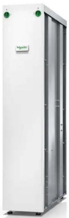
natural_image
Exterior view of a white industrial storage unit with green control knobs and a 'Schneider' logo on top (no other text or symbols visible)Legal Information
The Schneider Electric brand and any trademarks of Schneider Electric SE and its subsidiaries referred to in this guide are the property of Schneider Electric SE or subsidiaries. All other brands may be trademarks of their respective owners.
This guide and its content are protected under applicable copyright laws and furnished for informational use only. No part of this guide may be reproduced or transmitted in any form or by any means (electronic, mechanical, photocopying, recording, or otherwise), for any purpose, without the prior written permission of Schneider Electric.
Schneider Electric does not grant any right or license for commercial use of the or its content, except for a non-exclusive and personal license to consult it on ar is" basis. Schneider Electric products and equipment should be installed, operated, serviced, and maintained only by qualified personnel.
As standards, specifications, and designs change from time to time, information contained in this guide may be subject to change without notice.
To the extent permitted by applicable law, no responsibility or liability is assumed Schneider Electric and its subsidiaries for any errors or omissions in the information content of this material or consequences arising out of or resulting from the use information contained herein.

Go to
https://www.productinfo.schneider-electric.com/portals/ui/galaxyvs_ul/
or scan the QR code above for digital experience and translated manuals.
Table of Contents
Important Safety Instructions — SAVE THESE
INSTRUCTIONS....5
FCC Statement 6
Safety Precautions 6
Additional Safety Precautions After Installation....8
Electrical Safety 8
Battery Safety 9
Specifications 11
Maximum Short Circuit Rating 11
Specifications for 480 V Systems 11
Trip Settings for 480 V 11
Recommended Upstream Protection 480 V 12
Recommended Cable Sizes 480 V 13
Specifications for 208 V Systems ....14
Trip Settings for 200/208/220 V 14
Recommended Upstream Protection 200/208/220 V 14
Recommended Cable Sizes 200/208/220 V 15
Specifications for 400 V Systems ....16
Trip Settings for 400/415 V 16
Recommended Upstream Protection 400/415 V ....17
Recommended Cable Sizes 400/415 V....18
Recommended Bolt and Lug Sizes 19
Torque Specifications....19
Maintenance Bypass Cabinet Weights and Dimensions....20
Clearance 20
Environment....20
Online Diagrams....21
Overview of Installation Kits 22
Optional Seismic Kit GVSOPT003 26
Optional Kirk Key Kit GVSOPT004....27
Installation Procedure for Top Cable Entry 28
Installation Procedure for Bottom Cable Entry 30
Prepare the Maintenance Bypass Cabinet and the UPS for
Cables....31
Connect the Internal Power Cables 35
Install the Seismic Anchoring (Option) 37
Connect the Power Cables in a 10-80 kW Top Cable Entry
System....39
Connect the Power Cables in a 100-150 kW Top Cable Entry
System....41
Restrain the Cables 43
Connect the Power Cables in a Bottom Cable Entry System......4
Interconnect the UPS and the Maintenance Bypass Cabinet ....46
Connect the Signal Cables....51
Final Installation 54
Important Safety Instructions — SAVE THESE INSTRUCTIONS
Read these instructions carefully and look at the equipment to become familiar with it before trying to install, operate, service or maintain it. The following safe messages may appear throughout this manual or on the equipment to warn of potential hazards or to call attention to information that clarifies or simplifies a procedure.
The addition of this symbol to a “Danger” or “Warning” safety message indicates that an electrical hazard exists which will result in personal injury if the instructions are not followed.

This is the safety alert symbol. It is used to alert you to potential personal injury hazards. Obey all safety messages with this symbol to avoid possible injury or death.
⚠️ DANGER
DANGER indicates a hazardous situation which, if not avoided, will result in death or serious injury.
Failure to follow these instructions will result in death or serious injury.
▲WARNING
WARNING indicates a hazardous situation which, if not avoided, could result in death or serious injury.
Failure to follow these instructions can result in death, serious injury, or equipment damage.
▲CAUTION
CAUTION indicates a hazardous situation which, if not avoided, could result in minor or moderate injury.
Failure to follow these instructions can result in injury or equipment damage.
NOTICE
NOTICE is used to address practices not related to physical injury. The safety alert symbol shall not be used with this type of safety message.
Failure to follow these instructions can result in equipment damage.
Please Note
Electrical equipment should only be installed, operated, serviced, and maintained by qualified personnel. No responsibility is assumed by Schneider Electric for an consequences arising out of the use of this material.
A qualified person is one who has skills and knowledge related to the construct installation, and operation of electrical equipment and has received safety training to recognize and avoid the hazards involved.
FCC Statement
NOTE: This equipment has been tested and found to comply with the limits for a Class A digital device, pursuant to Part 15 of the FCC Rules. These limits are designed to provide reasonable protection against harmful interference when the equipment is operated in a commercial environment. This equipment generates, uses, and can radiate radio frequency energy and, if not installed and used in accordance with the instruction manual, may cause harmful interference to radio communications. Operation of this equipment in a residential area is likely to cause harmful interference in which case the user will be required to correct the interference at his own expense.
Any changes or modifications not expressly approved by the party responsible for compliance could void the user's authority to operate the equipment.
Safety Precautions
⚠️⚠️ DANGER
HAZARD OF ELECTRIC SHOCK, EXPLOSION, OR ARC FLASH
Read all instructions in the installation manual before installing or working on this product.
Failure to follow these instructions will result in death or serious injury.
⚠️ DANGER
HAZARD OF ELECTRIC SHOCK, EXPLOSION, OR ARC FLASH
Do not install the product until all construction work has been completed and the installation room has been cleaned.
Failure to follow these instructions will result in death or serious injury.
⚠️⚠️ DANGER
HAZARD OF ELECTRIC SHOCK, EXPLOSION, OR ARC FLASH
The product must be installed according to the specifications and requirements as defined by Schneider Electric. It concerns in particular the external and internal protections (upstream breakers, battery breakers, cabling, etc.) and environmental requirements. No responsibility is assumed by Schneider Electric if these requirements are not respected.
Failure to follow these instructions will result in death or serious injury.
⚠️ DANGER
HAZARD OF ELECTRIC SHOCK, EXPLOSION, OR ARC FLASH
The UPS system must be installed according to local and national regulations. Install the UPS according to:
- IEC 60364 (including 60364-4-41- protection against electric shock, 60364-4-42 - protection against thermal effect, and 60364-4-43 - protection against overcurrent), or
- NEC NFPA 70, or
• Canadian Electrical Code (C22.1, Part 1)
depending on which one of the standards apply in your local area.
Failure to follow these instructions will result in death or serious injury.
⚠️ DANGER
HAZARD OF ELECTRIC SHOCK, EXPLOSION, OR ARC FLASH
• Install the product in a temperature controlled indoor environment free of conductive contaminants and humidity.
• Install the product on a non-flammable, level and solid surface (e.g. concrete) that can support the weight of the system.
Failure to follow these instructions will result in death or serious injury.
⚠️ DANGER
HAZARD OF ELECTRIC SHOCK, EXPLOSION, OR ARC FLASH
The product is not designed for and must therefore not be installed in the following unusual operating environments:
- Damaging fumes
- Explosive mixtures of dust or gases, corrosive gases, or conductive or radiant heat from other sources
- Moisture, abrasive dust, steam or in an excessively damp environment
• Fungus, insects, vermin - Salt-laden air or contaminated cooling refrigerant
- Pollution degree higher than 2 according to IEC 60664-1
- Exposure to abnormal vibrations, shocks, and tilting
- Exposure to direct sunlight, heat sources, or strong electromagnetic fields Failure to follow these instructions will result in death or serious injury.
⚠️⚠️ DANGER
HAZARD OF ELECTRIC SHOCK, EXPLOSION, OR ARC FLASH
Do not drill or cut holes for cables or conduits with the gland plates installed do not drill or cut holes in close proximity to the UPS.
Failure to follow these instructions will result in death or serious injury.
⚠️ ⚠ WARNING
HAZARD OF ARC FLASH
Do not make mechanical changes to the product (including removal of cabinet parts or drilling/cutting of holes) that are not described in the installation manual
Failure to follow these instructions can result in death, serious injury, or equipment damage.
NOTICE
RISK OF OVERHEATING
Respect the space requirements around the product and do not cover the ventilation openings when the product is in operation.
Failure to follow these instructions can result in equipment damage.
Additional Safety Precautions After Installation
⚠️ DANGER
HAZARD OF ELECTRIC SHOCK, EXPLOSION, OR ARC FLASH
Do not install the UPS system until all construction work has been completed and the installation room has been cleaned. If additional construction work is needed in the installation room after this product has been installed, turn off the product and cover the product with the protective packaging bag the product was delivered in.
Failure to follow these instructions will result in death or serious injury.
Electrical Safety
This manual contains important safety instructions that should be followed during the installation and maintenance of the UPS system.
⚠️ DANGER
HAZARD OF ELECTRIC SHOCK, EXPLOSION, OR ARC FLASH
- Electrical equipment must be installed, operated, serviced, and maintained only by qualified personnel.
- Apply appropriate personal protective equipment (PPE) and follow safe electrical work practices.
- Disconnection devices for AC and DC must be provided by others, be readily accessible, and the function of the disconnect device marked for its function.
- Turn off all power supplying the UPS system before working on or inside the equipment.
- Before working on the UPS system, check for hazardous voltage between all terminals including the protective earth.
- The UPS contains an internal energy source. Hazardous voltage can be present even when disconnected from the mains supply. Before installing or servicing the UPS system, ensure that the units are OFF and that mains and batteries are disconnected. Wait five minutes before opening the UPS to allow the capacitors to discharge.
- The UPS must be properly earthed/grounded and due to a high leakage current, the earthing/grounding conductor must be connected first.
Failure to follow these instructions will result in death or serious injury.
When the UPS input is connected through external isolators that, when opened, isolate the neutral or when the automatic backfeed isolation is provided external to the equipment or is connected to an IT power distribution system, a label must be fitted at the UPS input terminals, and on all primary power isolators installed remotely from the UPS area and on external access points between such isolators and the UPS, by the user, displaying the following text (or equivalent in a language which is acceptable in the country in which the UPS system is installed):
⚠️ DANGER
HAZARD OF ELECTRIC SHOCK, EXPLOSION, OR ARC FLASH
Risk of voltage backfeed. Before working on this circuit: Isolate the UPS and check for hazardous voltage between all terminals including the protective earth.
Failure to follow these instructions will result in death or serious injury.
Battery Safety
⚠️ DANGER
HAZARD OF ELECTRIC SHOCK, EXPLOSION, OR ARC FLASH
- Battery circuit breakers must be installed according to the specifications and requirements as defined by Schneider Electric.
- Servicing of batteries must only be performed or supervised by qualified personnel knowledgeable of batteries and the required precautions. Keep unqualified personnel away from batteries.
- Disconnect charging source prior to connecting or disconnecting battery terminals.
- Do not dispose of batteries in a fire as they can explode.
- Do not open, alter, or mutilate batteries. Released electrolyte is harmful to the skin and eyes. It may be toxic.
Failure to follow these instructions will result in death or serious injury.
⚠️⚠️ DANGER
HAZARD OF ELECTRIC SHOCK, EXPLOSION, OR ARC FLASH
Batteries can present a risk of electric shock and high short-circuit current. The following precautions must be observed when working on batteries
- Remove watches, rings, or other metal objects.
- Use tools with insulated handles.
- Wear protective glasses, gloves and boots.
- Do not lay tools or metal parts on top of batteries.
- Disconnect the charging source prior to connecting or disconnecting battery terminals.
- Determine if the battery is inadvertently grounded. If inadvertently grounded, remove source from ground. Contact with any part of a grounded battery can result in electric shock. The likelihood of such shock can be reduced if such grounds are removed during installation and maintenance (applicable to equipment and remote battery supplies not having a grounded supply circuit).
Failure to follow these instructions will result in death or serious injury.
⚠️ DANGER
HAZARD OF ELECTRIC SHOCK, EXPLOSION, OR ARC FLASH
When replacing batteries, always replace with the same type and number of batteries or battery packs.
Failure to follow these instructions will result in death or serious injury.
▲CAUTION
RISK OF EQUIPMENT DAMAGE
- Mount the batteries in the UPS system, but do not connect the batteries until the UPS system is ready to be powered up. The time duration from battery connection until the UPS system is powered up must not exceed 72 hours of 3 days.
- Batteries must not be stored more than six months due to the requirement of recharging. If the UPS system remains de-energized for a long period, we recommend that you energize the UPS system for a period of 24 hours at least once every month. This charges the batteries, thus avoiding irreversible damage.
Failure to follow these instructions can result in injury or equipment damage.
Specifications
Maximum Short Circuit Rating
The maximum short circuit rating for the maintenance bypass cabinet is 65 kA RMS symmetrical.
Specifications for 480 V Systems
Trip Settings for 480 V


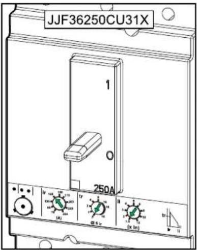
| UPS rating | Breaker type Ir (A) tr @ 6 Ir li (x In) | tr @ 6 Ir | li (x In) | ||||
| UIB/SSIB MBB/UOB | UIB/SSIB/MBB/UOB | UIB/SSIB MBB/UOB | |||||
| 20 kW | HJF36150CU31X | HJF36150CU31X | 50 | 1 | 4 | 0.5 | 4 |
| 30 kW | HJF36150CU31X | HJF36150CU31X | 50 | 1 | 5 | 0.5 | 5 |
| 40 kW | HJF36150CU31X | HJF36150CU31X | 70 | 1 | 5 | 0.5 | 5 |
| 50 kW | HJF36150CU31X | HJF36150CU31X | 80 | 1 | 5 | 0.5 | 5 |
| 60 kW | HJF36150CU31X | HJF36150CU31X | 100 | 1 | 12 | 0.5 | 12 |
| 80 kW | HJF36150CU31X | HJF36150CU31X | 125 | 1 | 12 | 0.5 | 12 |
| 100 kW | LJF36400CU31X | JJF36250CU31X | 175 | 1 | 7 | 0.5 | 10 |
| 120 kW | LJF36400CU31X | JJF36250CU31X | 200 | 1 | 8 | 0.5 | 12 |
| 150 kW | LJF36400CU31X | JJF36250CU31X | 250 | 1 | 8 | 0.5 | 12 |
Recommended Upstream Protection 480 V
| UPS rating | 20 kW 30 kW 40 kW 50 | kW | ||||||
| Input Bypass | Input Bypass | Input Bypass | Input Bypass | |||||
| Breaker type | HJF36100U31X | |||||||
| lr (A) 40 35 | 60 50 80 70 | 100 80 | ||||||
| tr @ 6 lr 0.5 | ||||||||
| li (x In) 1.5 | ||||||||
| UPS rating | 60 kW 80 kW 100 kW | 120 kW | 150 kW | kW | ||||||
| Input | Bypass | Input | Bypass | Input | Bypass | Input | Bypass | Input | Bypass | |
| Breaker type | HJ-F36150-U31X | HJ-F36100-U31X | JJ-F36250-U31X | HJ-F36150-U31X | JJF36250U31X | LJ-F36400-U31X | JJ-F36250-U31X | |||
| Ir (A) | 125 | 100 | 175 | 125 | 200 | 175 | 250 | 200 | 300 | 250 |
| tr @ 6 Ir 0.5 | ||||||||||
| li (x In) 1.5 | ||||||||||
Recommended Cable Sizes 480 V
⚠️ DANGER
HAZARD OF ELECTRIC SHOCK, EXPLOSION, OR ARC FLASH
All wiring must comply with all applicable national and/or electrical codes. The maximum allowable cable size is 4/0 AWG.
Failure to follow these instructions will result in death or serious injury.
NOTE: Overcurrent protection is to be provided by others.
Cable sizes in this manual are based on Table 310.15 (B)(16) of the National Electrical Code (NEC) with the following assertions:
- 90 °C (194 °F) conductors (75 °C (167 °F) termination)
• An ambient temperature of 30 °C (86 °F)
• Use of copper conductors
If the ambient temperature is greater than 30 °C (86 °F), larger conductors are be selected in accordance with the correction factors of the NEC.
Equipment grounding conductors (PE in this manual) are sized in accordance with NEC Article 250.122 and Table 250.122.
| UPS rating 20 kW | 30 kW 40 | kW 50 kW | 60 kW | 80 kW 100 | kW 120 kW | 150 kW | |||
| Input phases (AWG/kcmil) | 8 6 4 3 | 1 2/0 2 x | 1/0 2 x 1 | 0 2 x 1/0 | |||||
| Input PE (AWG/kcmil) | 10 8 8 6 | 6 6 4 2 | x 4 2 x 3 | ||||||
| Bypass/outputphases (AWG/kcmil) | 10 8 6 4 | 3 1 2/0 | 2 x | 1/0 2 x 1/0 | |||||
| Bypass PE/outputPE (AWG/kcmil) | 10 10 | 8 8 8 | 6 6 2 x | 6 2 x 4 | |||||
| Neutral (AWG/kcmil) 1 | 6 | 4 | 2 | 1/0 | 2/0 | 2 x 1/0 | 2 x 1/0 | 4 x 1/0 | 4 x 1/0 |
| DC +/- (AWG/kcmil) | 24 | 22 | 1/0 2 | 1/0 3 | 2/0 3 | 4/0 3 | 2 x 1/0 | 2 x 3/0 | 2 x 4/0 |
| DC PE (AWG/kcmil) | 8 6 6 | 6 6 4 4 3 | 2 x 2 |
NOTE: The DC cable sizes given here are recommendations – Always follow the specific instructions in the battery solution documentation for DC +/- and DC PE cable sizes.
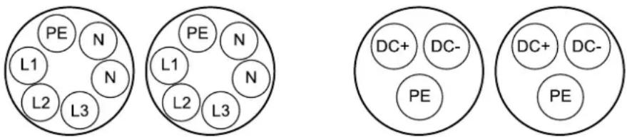
NOTE: For 120 kW, use two separate conduits for each of the input, bypass, and output cable sets. Organize cables as illustrated in each conduit to avoid eddy currents (heating).
NOTE: For 150 kW, use two separate conduits for each of the input, bypass, output, and DC cable sets. Organize cables as illustrated in each conduit to avoid eddy currents (heating).
Cable Organization in Separate Conduits for Input/Bypass/Output and DC

Specifications for 208 V Systems
Trip Settings for 200/208/220 V


| UPS rating | Breaker type Ir (A) tr @ | 6 Ir li (x ln) tr @ 6 | Ir li (x ln) | |||||
| UIB/SSIB MBB/UOB UIB | SSIB/MBB/UOB | UIB/SSIB MBB/UOB | ||||||
| 10 kW HJF36150CU31X HJF36150 | CU31X 50 50 1 | 4 0.5 | 4 | |||||
| 15 kW HJF36150CU31X HJF36150 | CU31X 60 60 1 | 5 0.5 | 5 | |||||
| 20 kW HJF36150CU31X HJF36150 | CU31X 80 80 1 | 5 0.5 | 5 | |||||
| 25 kW | HJF36150CU31X | HJF36150CU31X | 100 | 100 | 1 | 5 | 0.5 | 5 |
| 30 kW | HJF36150CU31X | HJF36150CU31X | 125 | 110 | 1 | 12 | 0.5 | 12 |
| 40 kW | HJF36150CU31X | HJF36150CU31X | 150 | 150 | 1 | 12 | 0.5 | 12 |
| 50 kW | LJF36400CU31X | JJF36250CU31X | 200 | 200 | 1 | 7 | 0.5 | 10 |
| 60 kW | LJF36400CU31X | JJF36250CU31X | 250 | 225 | 1 | 8 | 0.5 | 12 |
| 75 kW | LJF36400CU31X | JJF36250CU31X | 300 | 250 | 1 | 8 | 0.5 | 12 |
Recommended Upstream Protection 200/208/220 V
| UPS rating | 10 kW | 15 kW | 20 kW | 25 kW | ||||
| Input | Bypass | Input | Bypass | Input | Bypass | Input | Bypass | |
| Breaker type | HJF36100U31X | HJF36150-U31X | HJF36100-U31X | |||||
| lr (A) | 50 | 40 | 80 | 60 | 100 | 80 | 125 | 100 |
| tr @ 6 lr | 0.5 | |||||||
| li (x In) | 1.5 | |||||||
| UPS rating | 30 kW | 40 kW | 50 kW | 60 kW | 75 kW | |||||
| Input | Bypass | Input | Bypass | Input | Bypass | Input | Bypass | Input | Bypass | |
| Breaker type | HJF36150U31X | JJ-F36250-U31X | HJ-F36150-U31X | JJF36250U31X | LJ-F36400-U31X | JJ-F36250-U31X | LJF36400U31X | |||
| Ir (A) | 150 | 110 | 200 | 150 | 250 | 200 | 300 | 225 | 350 | 300 |
| tr @ 6 Ir | 0.5 | |||||||||
| li (x In) | 1.5 | |||||||||
Recommended Cable Sizes 200/208/220 V
⚠️ DANGER
HAZARD OF ELECTRIC SHOCK, EXPLOSION, OR ARC FLASH
All wiring must comply with all applicable national and/or electrical codes. The maximum allowable cable size is 4/0 AWG.
Failure to follow these instructions will result in death or serious injury.
NOTE: Overcurrent protection is to be provided by others.
Cable sizes in this manual are based on Table 310.15 (B)(16) of the National Electrical Code (NEC) with the following assertions:
- 90 °C (194 °F) conductors (75 °C (167 °F) termination)
• An ambient temperature of 30 °C (86 °F)
• Use of copper conductors
If the ambient temperature is greater than 30 °C (86 °F), larger conductors are be selected in accordance with the correction factors of the NEC.
Equipment grounding conductors (PE in this manual) are sized in accordance with NEC Article 250.122 and Table 250.122.
| UPS rating 10 kW | 15 kW 20 | kW 25 kW | 30 kW | 40 kW 50 | kW 60 kW | 75 kW | |||
| Input phases (AWG/kcmil) | 8 4 3 2 | 1/0 2 x 1/0 | 2 x 1/0 | 2 x 1/0 2 | x 2/0 | ||||
| Input PE (AWG/kcmil) | 10 8 8 6 | 6 6 2 x | 4 2 x 4 2 | x 3 | |||||
| Bypass/outputphases (AWG/kcmil) | 8 6 4 3 | 2 1/0 2 x | 1/0 2 x 1/0 | 2 x 1/0 | |||||
| Bypass PE/outputPE (AWG/kcmil) | 10 10 | 8 8 6 | 6 2 x 6 | 2 x 4 2 x | 4 | ||||
| Neutral (AWG/kcmil) 4 | 6 3 1 2/0 | 2 x 1/0 | 2 x 1/0 | 2 x 2/0 | 4 x 1/0 4 | x 1/0 | |||
| DC +/- (AWG/kcmil) | $0 | 65 | 45 | 45 | 25 | 1/05 | 2/05 | 4/05 | 2 x 1%0 |
| DC PE (AWG/kcmil) | 10 10 | 8 8 | 6 6 6 4 | 4 |
NOTE: The DC cable sizes given here are recommendations – Always follow the specific instructions in the battery solution documentation for DC +/- and DC PE cable sizes.
NOTE: For 50 kW, 60 kW, and 75 kW, use two separate conduits for each of the input, bypass, and output cable sets. Organize cables as illustrated in each conduit to avoid eddy currents (heating).
Cable Organization in Separate Conduits for Input/Bypass/Output and DC

Specifications for 400 V Systems
Trip Settings for 400/415 V
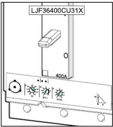
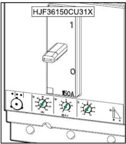

| UPS rating | Breaker type Ir (A) tr @ 6 Ir li (x In) tr @ | 6 Ir li (x In) | ||||||
| UIB/SSIB MBB/UOB UIB | SSIB/ MBB/UOB | UIB/SSIB MBB/UOB | ||||||
| 10 kW | HJF36150CU31X | HJF36150CU31X | 50 | 50 | 1 | 4 | 0.5 | 4 |
| 15 kW | HJF36150CU31X | HJF36150CU31X | 50 | 50 | 1 | 4 | 0.5 | 4 |
| 20 kW | HJF36150CU31X | HJF36150CU31X | 50 | 50 | 1 | 4 | 0.5 | 4 |
| 30 kW | HJF36150CU31X | HJF36150CU31X | 60 | 60 | 1 | 5 | 0.5 | 5 |
| 40 kW | HJF36150CU31X | HJF36150CU31X | 80 | 80 | 1 | 5 | 0.5 | 5 |
| 50 kW | HJF36150CU31X | HJF36150CU31X | 100 | 100 | 1 | 5 | 0.5 | 5 |
| 60 kW | HJF36150CU31X | HJF36150CU31X | 125 | 110 | 1 | 12 | 0.5 | 12 |
| 80 kW | HJF36150CU31X | HJF36150CU31X | 150 | 150 | 1 | 12 | 0.5 | 12 |
| 100 kW | LJF36400CU31X | JJF36250CU31X | 200 | 200 | 1 | 7 | 0.5 | 10 |
| 120 kW | LJF36400CU31X | JJF36250CU31X | 250 | 225 | 1 | 8 | 0.5 | 12 |
| 150 kW | LJF36400CU31X | JJF36250CU31X | 300 | 250 | 1 | 8 | 0.5 | 12 |
Recommended Upstream Protection 400/415 V
| UPS rating | 10 kW 15 kW 20 | kW 30 kW 40 | kW 50 kW | |||||||||
| Input By-pass | Input By-pass | Input By-pass | Input By-pass | Input By-pass | Input By-pass | |||||||
| Breaker type | HJF36060U31X HJF36100U31X HJ- | F3615-0U31X | HJ-F3610-0U31X | |||||||||
| Ir (A) 25 20 | 35 30 | 50 40 80 | 60 100 | 80 125 | 100 | |||||||
| tr @ 6 Ir 0.5 | ||||||||||||
| li (x In) 1.5 | ||||||||||||
| UPS rating | 60 kW | 80 kW | 100 kW | 120 kW | 150 kW | |||||
| Input | Bypass | Input | Bypass | Input | Bypass | Input | Bypass | Input | Bypass | |
| Breaker type | HJF36150U31X | JJ-F36250-U31X | HJ-F36150-U31X | JJF36250U31X | LJ-F36400-U31X | JJ-F36250-U31X | LJF36400U31X | |||
| Ir (A) | 150 | 110 | 200 | 150 | 250 | 200 | 300 | 225 | 350 | 300 |
| tr @ 6 Ir 0.5 | ||||||||||
| li (x In) 1.5 | ||||||||||
Recommended Cable Sizes 400/415 V
⚠️ DANGER
HAZARD OF ELECTRIC SHOCK, EXPLOSION, OR ARC FLASH
All wiring must comply with all applicable national and/or electrical codes. The maximum allowable cable size is 4/0 AWG.
Failure to follow these instructions will result in death or serious injury.
NOTE: Overcurrent protection is to be provided by others.
Cable sizes in this manual are based on Table 310.15 (B)(16) of the National Electrical Code (NEC) with the following assertions:
- 90 °C (194 °F) conductors (75 °C (167 °F) termination)
• An ambient temperature of 30 °C (86 °F) - Use of copper conductors
If the ambient temperature is greater than 30 °C (86 °F), larger conductors are selected in accordance with the correction factors of the NEC.
Equipment grounding conductors (PE in this manual) are sized in accordance with NEC Article 250.122 and Table 250.122.
| UPS rating 10 kW | 15 kW | 20 kW | 30 kW | 40 kW | 50 kW | 60 kW | 80 kW | 100 kW | 120 kW | 150 kW | ||
| Input phases (AWG/kcmil) | 8 8 8 | 4 3 2 | 1/0 | 2 x 1/0 | 2 x 1/0 | 2 x 1/0 | 2 x 2/0 | |||||
| Input PE (AWG/kcmil) | 10 | 10 | 10 | 8 | 8 | 6 | 6 | 6 | 2 x 4 | 2 x 4 | 2 x 3 | |
| Bypass/outputphases (AWG/kcmil) | 8 8 8 | 6 4 3 | 2 | 1/0 | 2 x 1/0 | 2 x 1/0 | 2 x 1/0 | |||||
| Bypass PE/outputPE (AWG/kcmil) | 10 | 10 | 10 | 10 | 8 | 8 | 6 | 6 | 2 x 6 | 2 x 4 | 2 x 4 | |
| Neutral (AWG/kcmil)6 | 8 8 6 | 3 1 2/0 | 2 x 1/0 | 2 x 1/0 | 2 x 2/0 | 4 x 1/0 | 4 x 1/0 | |||||
| DC +/- (AWG/kcmil) | 10 | 87 | 47 | 27 | 1/07 | 1/08 | 2/08 | 4/08 | 2 x 1/0 | 2 x 3/0 | 2 x 4/0 | |
| DC PE (AWG/kcmil) | 10 | 10 | 8 6 6 | 6 6 4 | 4 3 2 x 2 |
NOTE: The DC cable sizes given here are recommendations – Always follow the specific instructions in the battery solution documentation for DC +/- and DC PE cable sizes.
NOTE: For 100 and 120 kW, use two separate conduits for each of the input, bypass, and output cable sets. Organize cables as illustrated in each conduit to avoid eddy currents (heating).
NOTE: For 150 kW, use two separate conduits for each of the input, bypass, output, and DC cable sets. Organize cables as illustrated in each conduit to avoid eddy currents (heating).
Cable Organization in Separate Conduits for Input/Bypass/Output and DC
Recommended Bolt and Lug Sizes
NOTICE
RISK OF EQUIPMENT DAMAGE
Use only UL approved compression cable lugs.
Failure to follow these instructions can result in equipment damage.
Copper — One Hole Cable Lugs
| Cable size | Bolt size Cable lug type | Crimping tool Die | ||
| 10 AWG M8 | x 35 mm LCA10-56-L NA | NA | ||
| 8 AWG M8 | x 35 mm LCA8-56-L CT-720 | CD-720-1 Red P21 | ||
| 6 AWG M8 | x 35 mm LCA6-56-L CT-720 | CD-720-1 Blue P24 | ||
| 4 AWG M8 | x 35 mm LCA4-56-L CT-720 | CD-720-1 Gray P29 | ||
| 3 AWG M8 | x 35 mm LCA4-56-L CT-720 | CD-720-1 Gray P29 | ||
| 2 AWG M8 | x 35 mm LCA2-56-Q | CT-720 | CD-720-1 Brown | P33 |
| 1 AWG M8 | x 35 mm LCA1-56-E | CT-720 | CD-720-2 Green | P37 |
| 1/0 AWG | M8 x 35 mm | LCA1/0-56-X | CT-720 | CD-720-2 Pink P42 |
| 2/0 AWG | M8 x 35 mm | LCA2/0-56-X | CT-720 | CD-720-2 Black P45 |
| 3/0 AWG | M8 x 35 mm | LCA3/0-56-X | CT-720 | CD-720-2 Orange P50 |
| 4/0 AWG | M8 x 35 mm | LCA4/0-56-X | CT-720 | CD-720-3 Purple P54 |
Copper — Two Hole Cable Lugs
| Cable size | Bolt size Cable lug type | Crimping tool | Die | |
| 6 AWG | M10 x 35 mm | LCC6-12-L | CT-930 | CD-920-6 Blue P24 |
| 4 AWG M10 | x 35 mm | LCC4-12-L | CT-930 | CD-920-4 Gray P29 |
| 3 AWG M10 | x 35 mm | |||
| 2 AWG | M10 x 35 mm | LCC2-12-Q | CT-930 | CD-920-2 Brown P33 |
| 1 AWG | M10 x 35 mm | LCC1-12-E | CT-930 | CD-920-1 Green P37 |
| 1/0 AWG | M10 x 35 mm | LCC1/0-12-X | CT-930 | CD-920-1/0 Pink P42 |
| 2/0 AWG | M10 x 35 mm | LCC2/0-12-X | CT-930 | CD-920-2/0 Black P45 |
| 3/0 AWG | M10 x 35 mm | LCC3/0-12-X | CT-930 | CD-920-3/0 Orange P50 |
| 4/0 AWG | M10 x 35 mm | LCC4/0-12-X | CT-930 | CD-920-4/0 Purple P54 |
Torque Specifications
| Bolt size | Torque |
| M4 | 1.7 Nm (1.25 lb-ft / 15 lb-in) |
| M5 | 2.2 Nm (1.62 lb-ft / 19.5 lb-in) |
| M6 | 5 Nm (3.69 lb-ft / 44.3 lb-in) |
| M8 | 17.5 Nm (12.91 lb-ft / 154.9 lb-in) |
| M10 | 30 Nm (22 lb-ft / 194.7 lb-in) |
| M12 | 50 Nm (36.87 lb-ft / 442.5 lb-in) |
Maintenance Bypass Cabinet Weights and Dimensions
| Commercial reference | Weight kg (lbs) Height | mm (in) Width mm (in) | Depth mm (in) | |
| GVSBSU80G 110 (242.51) | 1485 (58.46) 318 (12.52) | 850 (33.46) |
Clearance
NOTE: Clearance dimensions are published for airflow and service access only. Consult with the local safety codes and standards for additional requirements in your local area.
Front View of the UPS and the Maintenance Bypass Cabinet

Environment
| Operating Storage | ||
| Temperature | 0 °C to 40 °C (32 °F to 104 °F) | -25 °C to 55 °C (-13 °F to 131 °F) |
| Relative humidity | 0-95% non-condensing | 0-95% non-condensing |
| Elevation | 0-3000 m (0-10000 feet) | |
| Protection class | IP20 | |
| Color | RAL 9003, gloss level 85% | |
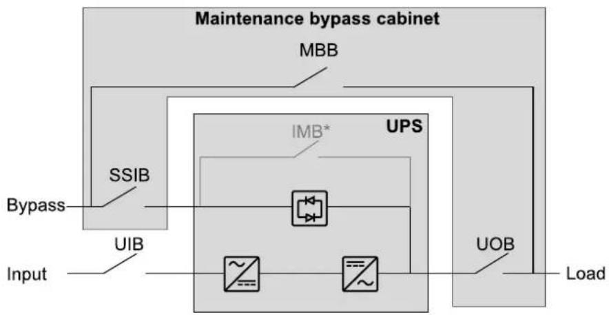
Online Diagrams
| UIB Unit input breaker | |
| SSIB Static switch input breaker | |
| MBB Maintenance bypass breaker | |
| IMB Internal maintenance breaker | |
| UOB Unit output breaker |
NOTE: The internal maintenance breaker IMB* in the UPS cannot be used with a maintenance bypass cabinet and the internal maintenance breaker IMB* must be padlocked in the open position.
Single Mains UPS System

flowchart
graph TD
    A["Input"] --> B["Maintenance bypass cabinet"]
    B --> C["MBB"]
    C --> D["UPS"]
    D --> E["IMB*"]
    E --> F["UIB"]
    F --> G["UOB"]
    G --> H["Load"]
Dual Mains UPS System
flowchart
graph TD
    A["Input"] --> B["UIB"]
    B --> C["SSIB"]
    C --> D["Bypass"]
    D --> E["UPS"]
    E --> F["IMB*"]
    F --> G["UOB"]
    G --> H["Load"]
    I["Maintenance bypass cabinet"] --> J["MBB"]
Overview of Installation Kits
Installation Kit 0M-100265 for 10-80 kW Maintenance Bypass Cabinet
| Part Used in Number of units | ||
| 0W49284 signal cable Connect the Signal Cables, page 51. 1 | page 51. 1 |  |
| 0W49283 signal cable 1 |  | |
| 0W99053 UPS PE cable Connect the Power Cables in a 10-80 kW Top CableEntry System, page 39 or Connect the Power Cables in aBottom Cable Entry System, page 45. | in a 10-80 kW Top CableEntry System, page 39 or Connect the Power Cables in aBottom Cable Entry System, page 45. | 1 |
| 0W99055 UPS output cables 1 |    | |
| 0W99056 UPS input/UPS bypass cables 1 |    | |
| 0W99054 UPS neutral cable 1 |  | |
| M8 nut with washer 10 |  | |
| M8 x 25 mm bolt with washer 10 |  | |
| Cable ties | 10 |
Installation Kit 0H-1717
Only for installation with UPS for internal batteries.
| Part Used in Number of units | ||
| Conduit box Install the Conduit Box, page 34 1 |  | |
| Rear plate 1 |  | |
| UPS input/UPS bypass cables 0W12758 1 |  | |
| UPS output cables 0W12761 1 |  | |
| M4 x 10 mm screw with washer 4 |  | |
| M8 nut with washer 3 |  | |
| M8 x 25 mm bolt with washer 3 |  | |
| M6 x 16 mm screw with washer 9 | [DKYH] | |
| M6 nut with washer 9 |  | |
| Support for side panel Prepare the Maintenance Bypass Cabinet and the UPS for Cables, page 31 | 10  | |
Installation Kit 0M-100247 for 100-150 kW Maintenance Bypass Cabinet
| Part Used in Number of units | ||
| 0W49195 UPS input cables (for dual mains) Connect the Power Cables in a 100-150 kW Top Cable Entry System, page 41. | 1 | |
| M8 nut with washer 6 |  | |
| M8 x 25 mm bolt with washer 6 |  | |
| Cable ties 10 | ||
Installation Kit 0M-100250 for 100-150 kW Maintenance Bypass Cabinet
| Part Used in Number of units | ||
| 0W49194 UPS DC cables Connect the Power Cables | Entry System, page 41 | 1 |
| M8 nut with washer 6 |  | |
| M8 x 25 mm bolt with washer 6 |  | |
| Cable ties 10 |  |
Installation Kit 0M-100264 for 100-150 kW Maintenance Bypass Cabinet
| Part Used in Number of units | ||
| 0W49284 signal cable Connect the Signal Cables, page 51. 1 | page 51. 1 |  |
| 0W49283 signal cable 1 |  | |
| 0W99057 UPS PE cable Connect the Power Cables in a 100-150 kW Top CableEntry System, page 41, or Connect the Power CableBottom Cable Entry System, page 45. | 1 .. .. | |
| 0W12375 UPS output cables 1 |  .. .. | |
| 0W99058 UPS input/UPS bypass cables 1 |  .. .. | |
| 0W99052 UPS neutral cable 1 |  .. .. | |
| M8 nut with washer 11 |  | |
| M8 x 25 mm bolt with washer 11 |  | |
| Cable ties | 10 | |
Optional Seismic Kit GVSOPT003
| Part Used in Number of units | ||
| Rear anchor Install the Seismic Anchoring (Option), | page 37 and Final Installation, page 54. | 1 |
| Front anchoring bracket 1 |  | |
| Rear anchoring bracket 1 |  | |
| M8 x 20 mm bolt 6 |  |
Optional Kirk Key Kit GVSOPT004
| Part Used in Number of units | ||
| Support plate The optional kirk key kit must be installed by a Schneider Electric field service representative. Contact Schneider Electric. | 2 | |
| Flathead screw 8 | [HBV3] | |
| Push-button 1 |  | |
| Top support plate 1 |  | |
| Electromechanical key interlock (SKRU) 1 |  | |
| Mechanical key interlock 2 |  | |
| Label 1 |  | |
| M6 nut with washer 2 |  | |
| 0W12675 signal cable 1 | [4XCC8] | |
| 0W49239 signal cable 1 |  | |
Installation Procedure for Top Cable Entry
Installation without Conduit Box – Single Mains Installation with Conduit Box – Single Mains

flowchart
graph TD
    A["UPS"] --> B["Input"]
    B --> C["Load"]
    C --> D["DC"]
    E["Maintenance bypass cabinet"] --> F["Output"]

flowchart
graph TD
    A["DC"] --> B["UPS"]
    C["Input"] --> D["Maintenance bypass cabinet"]
    E["Load"] --> D
    B --> D
Installation without Conduit Box - Dual Mains Installation with Conduit Box - Dual Mains

flowchart
graph TD
    A["UPS"] --> B["Maintenance bypass cabinet"]
    C["Input"] --> D["DC"]
    E["Bypass"] --> F["DC"]
    G["Load"] --> H["DC"]

flowchart
graph TD
    A["DC"] --> B["UPS"]
    C["Input"] --> B
    D["Load"] --> E["Maintenance bypass cabinet"]
    F["Bypass"] --> E
    B --> G["Green arrow indicates transition or break point"]
Signal cable Power cable
▲CAUTION
TIP HAZARD
Do not remove the transportation brackets from the maintenance bypass cabinet until it is time to anchor it to the floor or interconnect it with the UPS.
Failure to follow these instructions can result in injury or equipment damage.
- Follow the UPS manual to prepare the UPS for installation.
- Prepare the Maintenance Bypass Cabinet and the UPS for Cables, page 31.
- For system with conduit box: Install the Conduit Box, page 34
- Connect the Internal Power Cables, page 35.
-
Install the Seismic Anchoring (Option), page 37.
-
Perform one of the following:
-
Connect the Power Cables in a 10-80 kW Top Cable Entry System, pag 39, or
-
Connect the Power Cables in a 100-150 kW Top Cable Entry System, page 41.
-
Interconnect the UPS and the Maintenance Bypass Cabinet, page 46.
-
Connect the Signal Cables, page 51.
-
Final Installation, page 54.
-
Follow the UPS installation manual to connect the power cables from the maintenance bypass cabinet in the UPS and to complete the rest of the U installation.
Installation Procedure for Bottom Cable Entry
Single Mains

flowchart
graph TD
    A["UPS"] --> B["DC"]
    C["Maintenance bypass cabinet"] --> D["Input"]
    C --> E["Load"]
Signal cable Power cable
Dual Mains
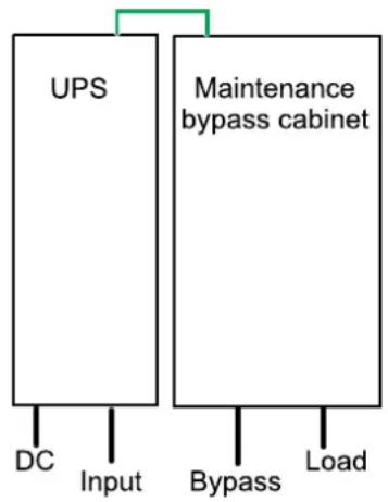
flowchart
graph TD
    A["UPS"] -->|DC Input| B["DC"]
    A -->|Bypass| C["Load"]
    A -->|Maintenance bypass cabinet| D["Maintenance bypass cabinet"]
▲CAUTION
TIP HAZARD
Do not remove the transportation brackets from the maintenance bypass cabinet until it is time to anchor it to the floor or interconnect it with the UPS.
Failure to follow these instructions can result in injury or equipment damage.
- Follow the UPS manual to prepare the UPS for installation.
- Prepare the Maintenance Bypass Cabinet and the UPS for Cables, page 31.
- For system with conduit box: Install the Conduit Box, page 34
- Connect the Internal Power Cables, page 35.
- Install the Seismic Anchoring (Option), page 37.
- Connect the Power Cables in a Bottom Cable Entry System, page 45.
- Interconnect the UPS and the Maintenance Bypass Cabinet, page 46.
- Connect the Signal Cables, page 51.
- Final Installation, page 54.
- Follow the UPS installation manual to connect the power cables from the maintenance bypass cabinet in the UPS and to complete the rest of the UPS installation.
Prepare the Maintenance Bypass Cabinet and the UPS for Cables
DANGER
HAZARD OF ELECTRIC SHOCK, EXPLOSION, OR ARC FLASH
Do not drill or cut holes for power cables or conduits with the gland plate installed and do not drill or cut holes in close proximity to the maintenance bypass cabinet.
Failure to follow these instructions will result in death or serious injury.
- Remove the front panel from the maintenance bypass cabinet.
Front View of the Maintenance Bypass Cabinet
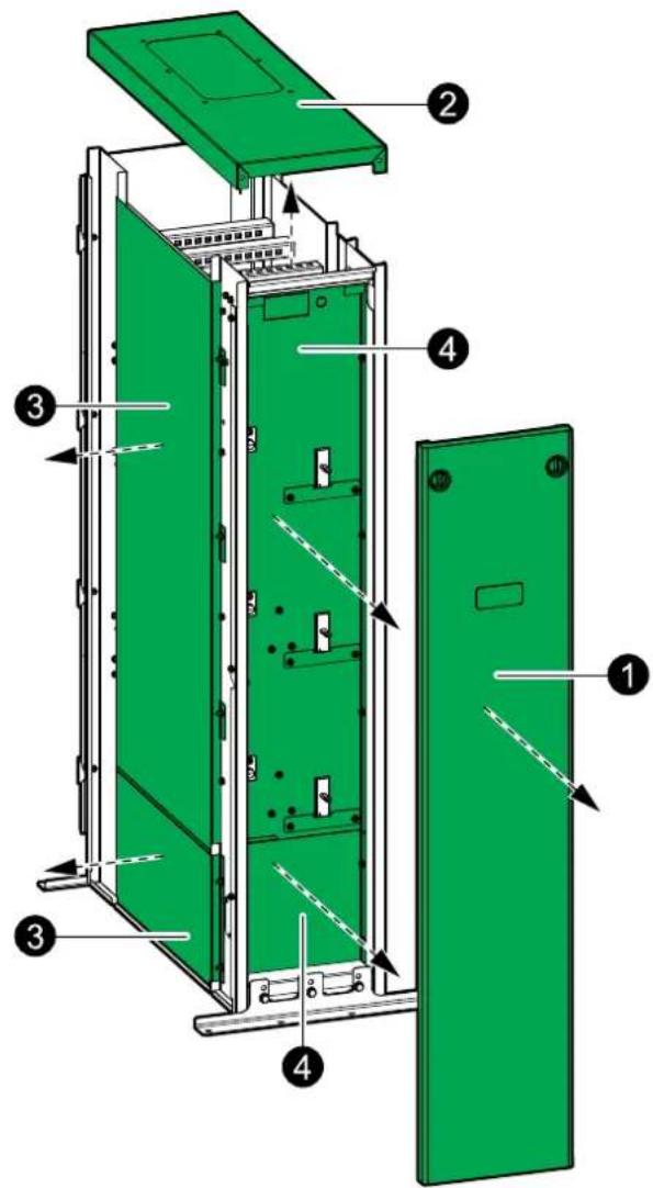
- Remove the top cover from the maintenance bypass cabinet.
- Remove the upper and lower left side plate from the maintenance bypass cabinet.
-
Remove the lower and upper front plate from the maintenance bypass cabinet.
-
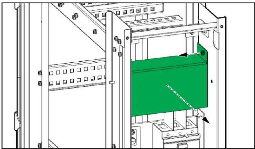
Remove the transparent plate above the top breaker.
Front View of the Maintenance Bypass Cabinet
natural_image
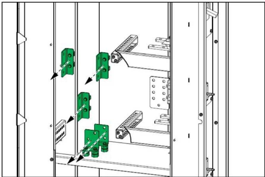
Technical line drawing of a mechanical assembly with green panel and mounting brackets (no text or symbols)- Only for bottom cable entry in 100-150 kW maintenance bypass cabinet: Remove the indicated busbars and insulators in the maintenance bypass cabinet for more cable routing space.
Left Side View of the 100-150 kW Maintenance Bypass Cabinet
- Remove the right side panel from the UPS and reinstall the side panel on right side of the maintenance bypass cabinet. For installation with a UPS for internal batteries, install the 10 supports (A) from installation kit 0H-1717. Reuse the screws from the UPS.

- Only for top cable entry system:
a. Remove the gland plate from the top cover of the maintenance bypass cabinet.
b. Drill or punch holes for power cables or conduits in the gland plate. Conduits are not provided.
c. Reinstall the gland plate in the top cover of the maintenance bypass cabinet.
- Only for bottom cable entry system:
a. Remove the gland plate from the bottom of the maintenance bypass cabinet.
b. Drill or punch holes for power cables or conduits in the gland plate. Conduits are not provided.
c. Reinstall the gland plate in the bottom of the maintenance bypass cabinet
- Reinstall the top cover on the maintenance bypass cabinet with four screws
- Remove the middle rear plate on the maintenance bypass cabinet. Save the nuts for installing the conduit box.
- Remove the knockouts from the conduit box.
- Install the conduit box on the maintenance bypass cabinet with the nuts from step 1.
- Install the provided UPS input/UPS bypass cables 0W12758 and UPS output cables 0W12761 in the conduit box.
- Install the rear plate on the conduit box
Rear View of the Maintenance Bypass Cabinet

Connect the Internal Power Cables
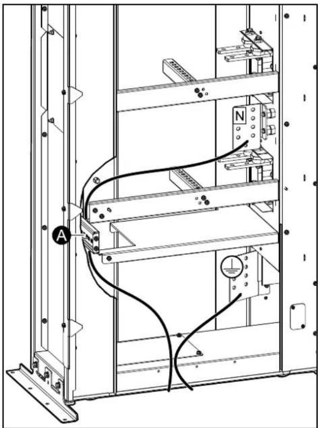
Fasten the cables to the beam with a cable tie where marked with an (A) in illustrations.
-
Connect the provided UPS PE cable to the PE busbar and route the cable through the left side or through the rear of the maintenance bypass cabinet
-
Connect the provided UPS N cable to the N busbar and route the cable through the left side or through the rear of the maintenance bypass cabinet
Left Side View of the Maintenance Bypass Cabinet Side View of the Maintenance Bypass Cabinet without Conduit Box with Conduit Box

-
Perform one of the following:
-
Only for single mains system: Connect the provided UPS input cables to the unit input breaker UIB (L1, L2, L3) and route the cables out through left side or through the rear of the maintenance bypass cabinet.
- Only for dual mains system: Connect the provided UPS bypass cables to the static switch input breaker SSIB (L1, L2, L3) and route the cables out through the left side or through the rear of the maintenance bypass cabinet.
Maintenance Bypass Cabinet without Conduit Maintenance Bypass Cabinet with Conduit Box
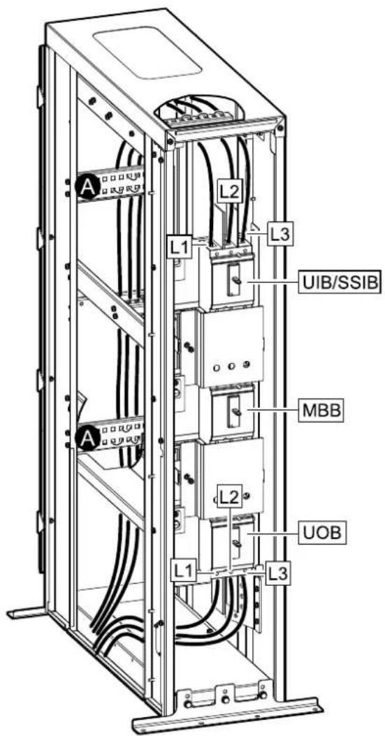
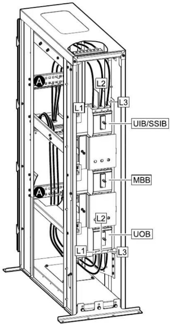
- Connect the provided UPS output cables to the unit output breaker UOB (L1 L2, L3) and route the cables out through the left side or through the rear c maintenance bypass cabinet.
Install the Seismic Anchoring (Option)
Use the optional installation kits GVSOPT002 (shipped with the UPS) and GVSOPT003 for this procedure.
-
Interconnect the rear anchors for the UPS (on the left) and the maintenance bypass cabinet (on the right) with the interconnection plate and four M8 bol (provided).
-
Mount the rear anchor(s) to the floor. Use appropriate hardware for the floor type - the hole diameter in the rear anchor is 14 mm.
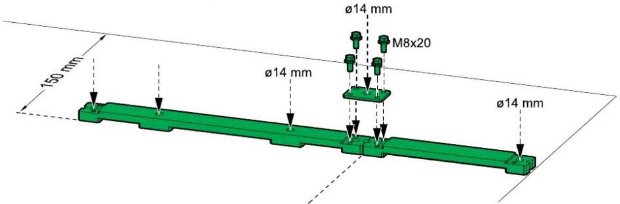
-
Remove the transportation brackets from the maintenance bypass cabinet.
-
Install the rear anchoring brackets on the UPS and the maintenance bypass cabinet with the M8 bolts (provided).
Rear View of the Maintenance Bypass Cabinet

- Push the maintenance bypass cabinet into position so the rear anchoring bracket connects to the rear anchor. The front anchoring bracket is installed in the final installation steps.
NOTE: Do not push the UPS into position yet.
Rear View of the Maintenance Bypass Cabinet

natural_image
Green mechanical component with mounting bracket and mounting base (no text or symbols visible)Connect the Power Cables in a 10-80 kW Top Ca Entry System
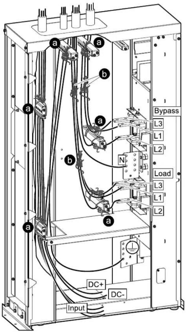
- The power cables must be restrained with 3/8 nylon rope:
a. Tie the power cables to the beams with rope as illustrated. Make sure that the rope holds the cables tightly in place. Note that L2 is routed under the beam and L1 and L3 is routed over the beam in front of t busbars.
b. Tie the power cables together with rope as illustrated halfway between the two beams. See Restrain the Cables, page 43 for restrain method.
Left Side View of the Maintenance Bypass Cabinet Side View of the Maintenance Bypass Cabinet - Single Mains - Dual Mains

-
Perform one of the following:
-
Only for single mains system: Route the input cables and load cables through the top of the maintenance bypass cabinet and connect to the PE busbar, the input busbars, and the load busbars.
-
Only for dual mains system: Route the bypass cables and load cables through the top of the maintenance bypass cabinet and connect to the PE busbar, bypass busbars, and the load busbars.
-
Only for dual mains system:
-
For top cable entry without conduit box: Route the input cables through the top of the maintenance bypass cabinet and to the bottom of the maintenance bypass cabinet. When the UPS has been installed, route the input cables through the left side into the UPS. Follow the UPS installation manual to connect the input cables.
-
For top cable entry with conduit box: When the UPS has been installed, route the input cables through the conduit box of the UPS. Follow the UF installation manual to connect the input cables.
-
Perform one of the following:
-
For top cable entry without conduit box: Route the DC cables through the top of the maintenance bypass cabinet and to the bottom of the maintenance bypass cabinet. When the UPS has been installed, route the DC cables through the left side into the UPS. Follow the UPS installation manual to connect the DC cables.
- For top cable entry with conduit box: When the UPS has been installed, route the DC cables through the conduit box of the UPS. Follow the UPS installation manual to connect the DC cables.
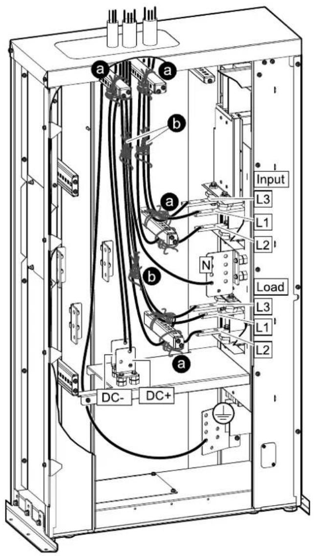
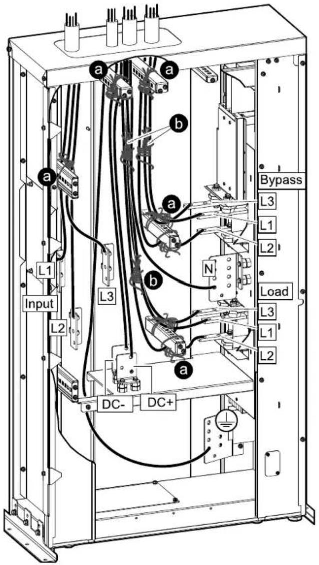
Connect the Power Cables in a 100-150 kW Top Cable Entry System
- The power cables must be restrained with 3/8 nylon rope:
a. Tie the power cables to the beams with rope as illustrated. Make sure that the rope holds the cables tightly in place. Note that L2 is routed under the beam and L1 and L3 is routed over the beam in front of t busbars.
b. Tie the power cables together with rope as illustrated halfway between the two beams. See Restrain the Cables, page 43 for restrain method.
Left Side View of the Maintenance Bypass Cabinet Side View of the Maintenance Bypass Cabinet - Single Mains - Dual Mains
- Perform one of the following:
- Only for single mains system: Route the input cables and the load cables through the top of the maintenance bypass cabinet and connect to the PE busbar, the input busbars and the load busbars.
- Only for dual mains system: Route the input cables, the bypass cables and the load cables through the top of the maintenance bypass cabinet and connect to the PE busbar, the input busbars, the bypass busbars, and the load busbars.
-
Route the DC cables through the top of the maintenance bypass cabinet and connect to the PE busbar and the DC busbars (DC+, DC-).
-
Connect the provided UPS DC cables to the DC busbars (DC+, DC-) and route the cables out through the left side of the maintenance bypass cabinet. Fasten the cables to the beam with cable ties.
-
Only for dual mains system: Connect the provided UPS input cables to the input busbars and route the cables out through the left side of the maintenance bypass cabinet. Fasten the cables to the beam with cable ties.
Left Side View of the Maintenance Bypass Cabinet

Restrain the Cables
Use 3/8 in nylon rope to restrain the cables.
- Wrap the rope around the cables (a). Wrap the cables four times leaving (3 ft) of excess rope at the first end (b). Pull rope (c) taut.

* Unsupported cable length.
- Wrap rope (a) several times until the space between the first two sets of cables is completely filled. Weave final rope loop underneath the previous loop (b). Bring rope (c) through the other open area and pull the rope tau

- Wrap rope (a) several times until the space between the second and the this set of cables is completely filled. Wave the final rope loop (b) underneath the previous loop as shown. Pull the rope taut.

- Tie rope End 1 and End 2 together as shown. The rope must be taut. Cut excess rope and tape ends to prevent fraying.
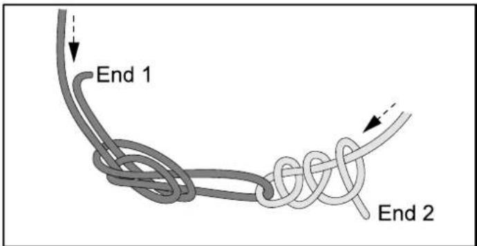
- Repeat the procedure where needed.
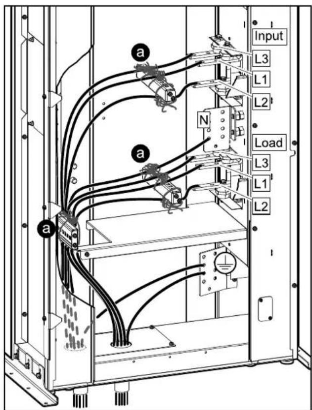
Connect the Power Cables in a Bottom Cable Ent System
NOTE: DC cables are routed through the bottom or through the conduit box the UPS. Follow the UPS installation manual to install the DC cables.
NOTE: Input cables in dual mains systems are routed through the bottom o through the conduit box of the UPS. Follow the UPS installation manual to install the input cables.
- Perform one of the following:
- Only for single mains system: Route the input cables and the load cables through the bottom of the maintenance bypass cabinet and connect to the PE busbar, the input busbars, and the load busbars.
- Only for dual mains system: Route the bypass cables and the load cables through the bottom of the maintenance bypass cabinet and connect to the PE busbar, the bypass busbars, and the load busbars.
- The power cables must be restrained with 3/8 nylon rope:
a. Tie the power cables to the beams with rope as illustrated. Make sure that the rope holds the cables tightly in place. Note that L2 is routed under the beam and L1 and L3 is routed over the beam in front of t busbars.
Left Side View of the Maintenance Bypass Cabinet Side View of the Maintenance Bypass Cabinet - Single Mains - Dual Mains

Interconnect the UPS and the Maintenance Bypass Cabinet
- Reinstall the left upper side plate and the transparent plate on the maintenance bypass cabinet.
Left Side View of the Maintenance Bypass Cabinet

- Only with conduit box: Reinstall the left lower side plate.
-
Remove the transportation brackets from the maintenance bypass cabinet, if not already removed for seismic anchoring.
-
Remove the three interconnection screws from the left side of the maintenance bypass cabinet. Save for interconnection.
Front View of the UPS and the Maintenance Bypass Cabinet

-
Position the UPS close to the maintenance bypass cabinet with a little free space between the cabinets.
-
Push the UPS into place up against the maintenance bypass cabinet. The rear bracket on the maintenance bypass cabinet must connect to the UPS.
Rear View of the Maintenance Bypass Cabinet and the UPS

natural_image
Technical line drawing of a mechanical cabinet or enclosure with a green panel and an inset close-up showing internal components (no text or symbols)- Install the three interconnection screws between the UPS and the maintenance bypass cabinet as shown.
Front View of the UPS and the Maintenance Bypass Cabinet
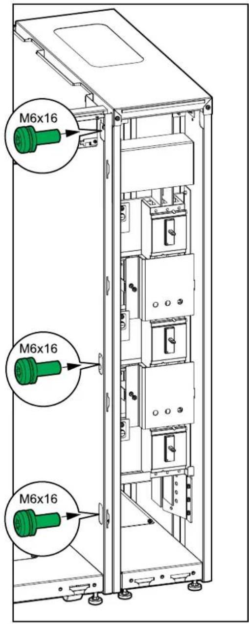
- Lower the front and rear leveling feet on the UPS and the maintenance bypass cabinet with a wrench until they connect with the floor. Use a bubble leveler to check that the UPS and maintenance bypass cabinet are level.
Front View of the UPS

natural_image
Technical diagram of a mechanical assembly with green adjustment knobs and mounting points (no text or symbols)CAUTION
RISK OF EQUIPMENT DAMAGE
Do not move the cabinet after the leveling feet have been lowered.
Failure to follow these instructions can result in injury or equipment damage.
Connect the Signal Cables
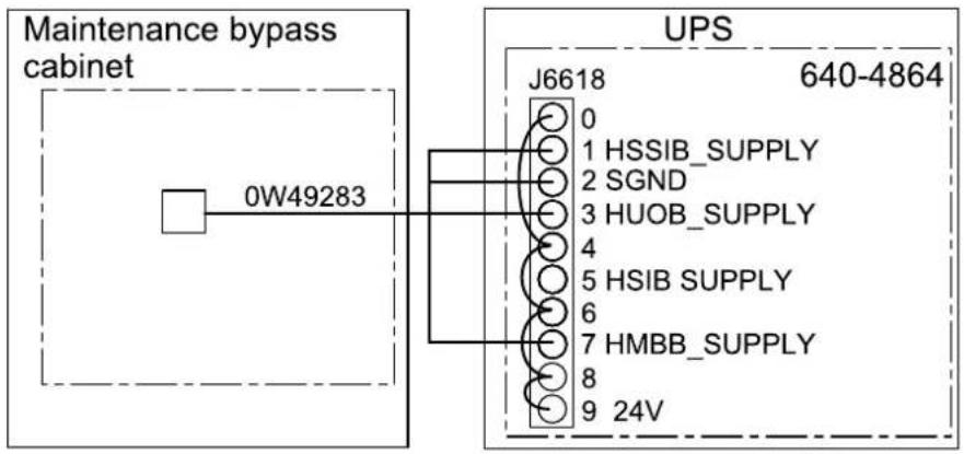
- Connect the provided Class 2/SELV signal cable 0W49283 to board 640-4864 in the UPS as shown.
Single Mains System

flowchart
graph TD
    A["Maintenance bypass cabinet"] --> B["0W49283"]
    B --> C["UPS"]
    C --> D["J6618 640-4864"]
    C --> E["0 HSSIB_SUPPLY"]
    C --> F["1 SGND"]
    C --> G["2 HUOB_SUPPLY"]
    C --> H["3"]
    C --> I["4"]
    C --> J["5 HSIB_SUPPLY"]
    C --> K["6"]
    C --> L["7 HMBB_SUPPLY"]
    C --> M["8"]
    C --> N["9 24V"]
Dual Mains System
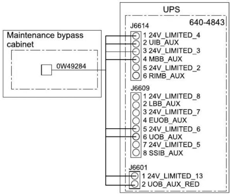
- Connect the non-Class 2/non-SELV signal cable 0W49284 to board 640-4843 in the UPS as shown.
Single Mains System
Dual Mains System

-
Route the signal cables down through the cable channel in the right side of the UPS and into the maintenance bypass cabinet through the cable entry opening.
-
Connect the signal cables at the cable connection point in the maintenance bypass cabinet.

Final Installation
- Reinstall the upper and lower front plate.
Front View of the Maintenance Bypass Cabinet

natural_image
Technical line drawing of a vertical electronic device casing with green internal compartments and mounting points (no text or symbols)- Only for dual mains: Add the labels SSIB, HSSIB, and the diagram label the upper front plate. The labels are provided with this manual.
Front View of the Maintenance Bypass Cabinet Front View of the Maintenance Bypass Cabinet - Single Mains Dual Mains


- Only for seismic anchoring:
a. Install the seismic front anchoring bracket on the maintenance bypass cabinet with the provided M8 bolts.
b. Mount the seismic front anchoring bracket on the maintenance bypass cabinet to the floor. Use appropriate hardware for the floor type – the diameter in the front anchoring bracket is 18 mm.
Front View of the Maintenance Bypass Cabinet

- Reinstall the front panel on the maintenance bypass cabinet:
a. Insert the two taps in the bottom of the front panel in the maintenance bypass cabinet at a tilted angle.
b. Reconnect the front panel strap to the maintenance bypass cabinet.
c. Close the front panel and lock with the two locking knobs.
Front Right View of the Maintenance Bypass Cabinet

natural_image
Technical line drawing of a device casing with internal components and a magnified inset showing a tool interacting with a component (no text or symbols present)- Follow the UPS installation manual to connect the internal power cables in the UPS.
Schneider Electric
As standards, specifications, and design change from time to time, please ask for confirmation of the information given in this publication.





- Maintenance Bypass Cabinet
- Installation
- Legal Information
- Table of Contents
- Important Safety Instructions — SAVE THESE INSTRUCTIONS
- ⚠️ DANGER
- ▲WARNING
- ▲CAUTION
- NOTICE
- Please Note
- FCC Statement
- Safety Precautions
- ⚠️⚠️ DANGER
- HAZARD OF ELECTRIC SHOCK, EXPLOSION, OR ARC FLASH
- ⚠️ ⚠ WARNING
- HAZARD OF ARC FLASH
- RISK OF OVERHEATING
- Additional Safety Precautions After Installation
- Electrical Safety
- Battery Safety
- RISK OF EQUIPMENT DAMAGE
- Specifications
- Maximum Short Circuit Rating
- Specifications for 480 V Systems
- Recommended Cable Sizes 480 V
- Cable Organization in Separate Conduits for Input/Bypass/Output and DC
- Specifications for 208 V Systems
- Recommended Upstream Protection 200/208/220 V
- Recommended Cable Sizes 200/208/220 V
- Specifications for 400 V Systems
- Recommended Cable Sizes 400/415 V
- Recommended Bolt and Lug Sizes
- Torque Specifications
- Maintenance Bypass Cabinet Weights and Dimensions
- Clearance
- Online Diagrams
- Single Mains UPS System
- Dual Mains UPS System
- Overview of Installation Kits
- Installation Kit 0M-100265 for 10-80 kW Maintenance Bypass Cabinet
- Installation Kit 0H-1717
- Installation Kit 0M-100247 for 100-150 kW Maintenance Bypass Cabinet
- Installation Kit 0M-100250 for 100-150 kW Maintenance Bypass Cabinet
- Installation Kit 0M-100264 for 100-150 kW Maintenance Bypass Cabinet
- Installation Procedure for Top Cable Entry
- TIP HAZARD
- Installation Procedure for Bottom Cable Entry
- Prepare the Maintenance Bypass Cabinet and the UPS for Cables
- DANGER
- Connect the Internal Power Cables
- Install the Seismic Anchoring (Option)
- Connect the Power Cables in a 10-80 kW Top Ca Entry System
- Connect the Power Cables in a 100-150 kW Top Cable Entry System
- Restrain the Cables
- Connect the Power Cables in a Bottom Cable Ent System
- Interconnect the UPS and the Maintenance Bypass Cabinet
- CAUTION
- Connect the Signal Cables
- Final Installation
Brand : APC
Model : Galaxy VS GVSOPT004
Category : Electrical cabinet