Shapeshifter - Keyboard Intellijel - Free user manual and instructions
Find the device manual for free Shapeshifter Intellijel in PDF.


| Type | Dual Digital Wavetable Oscillator Module |
| Width | 26 HP |
| Depth | 40 mm |
| Power Consumption | +195 mA (typical), -50 mA from ±12V rails |
| Wavetable Banks | 128 banks, 8 waveforms each (1024 total) |
| Sample Resolution | 16-bit, 512 samples per waveform |
| Preset Memory | 100 user-programmable slots with 8-character names |
| Vocoder | 64-band, with selectable carrier and modulator |
| Analog Wave Folder | Based on μFold II; CV controllable |
| Sync Modes | 9 modes: Hard, Soft, Rev, Hold, 1shot, Bump, 2=1, 1=2, Off |
| Chord Mode | 8-voice unison with 64 chord types; detune and drive |
| Combination Modes | 8 modes: osc1, ring, min, pong, inlv, and, xor, gLcH |
| Modulation Inputs | 8 jacks: RATIO, IFM, FM1, FOLD CV, MOD A, SHAPE1, SHAPE2, MOD B |
| Pitch Inputs | PITCH1 and PITCH2 (1V/oct); PITCH2 normalled to PITCH1 |
| Outputs | OUT1, OUT2 (12Vp-p), PULSE (0-5V), FOLD (10Vp-p) |
| Delay/Echo | Comb filter/delay line; time set by OSC2 period |
| Percussion Mode | Envelope with exponential decay; trigger/gate via SYNC input |
| Firmware Upgrade | Via USB-Blaster and Altera Quartus Programmer (JTAG) |
| Weight | Approx. 200 g (estimate) |
| Warranty | 2 years against defects in materials and workmanship |
Frequently Asked Questions - Shapeshifter Intellijel
User questions about Shapeshifter Intellijel
0 question about this device. Answer the ones you know or ask your own.
Ask a new question about this device
Download the instructions for your Keyboard in PDF format for free! Find your manual Shapeshifter - Intellijel and take your electronic device back in hand. On this page are published all the documents necessary for the use of your device. Shapeshifter by Intellijel.
USER MANUAL Shapeshifter Intellijel
The SHAPESHIFTER is a dual digital voltage controlled wavetable-based oscillator in a 26-HP Eurorack format.
The wavetables consists of 128 banks, each with 8 individual 512-sample waveforms, for a total of 1024 waves. The choice of waveform within the currently selected bank is under voltage control. There is smooth interpolation between the waveforms within a bank, allowing a very wide range of different possible waveshapes. Oscillator 1 can be operated in a CHORD mode, which runs 8 copies of the oscillator in parallel with adjustable detuning, leading to very fat, rich waveforms. The oscillators have extensive modulation capabilities including audio rate (98KHz) Frequency and Phase Modulation (FM and PM) via external sources. Nonlinear combination processes allow the outputs of the two oscillators to interact to generate complex timbres and sonic textures. The SHAPESHIFTER module also includes the analog wave folder circuitry from the intellijel μFold II module to add analog warmth and metallic rasps to the digital output.
The module includes a sophisticated preset mode where panel settings can be stored. There are 100 user-prgrammable preset memory slots. The capabilities of the preset mode is not limited to mere passive storage of settings, however. In this mode the user can also step through, or sequence, the settings, either in order or randomly in response to pulses input to the external sync input. This gives the user the ability to generate complex sequences of sounds. The preset mode also allows the user to morph between the current panel settings and a preset providing a very powerful real-time performance tool.
But, there is one more thing ... the SHAPESHIFTER also includes a 64-band vocoder!
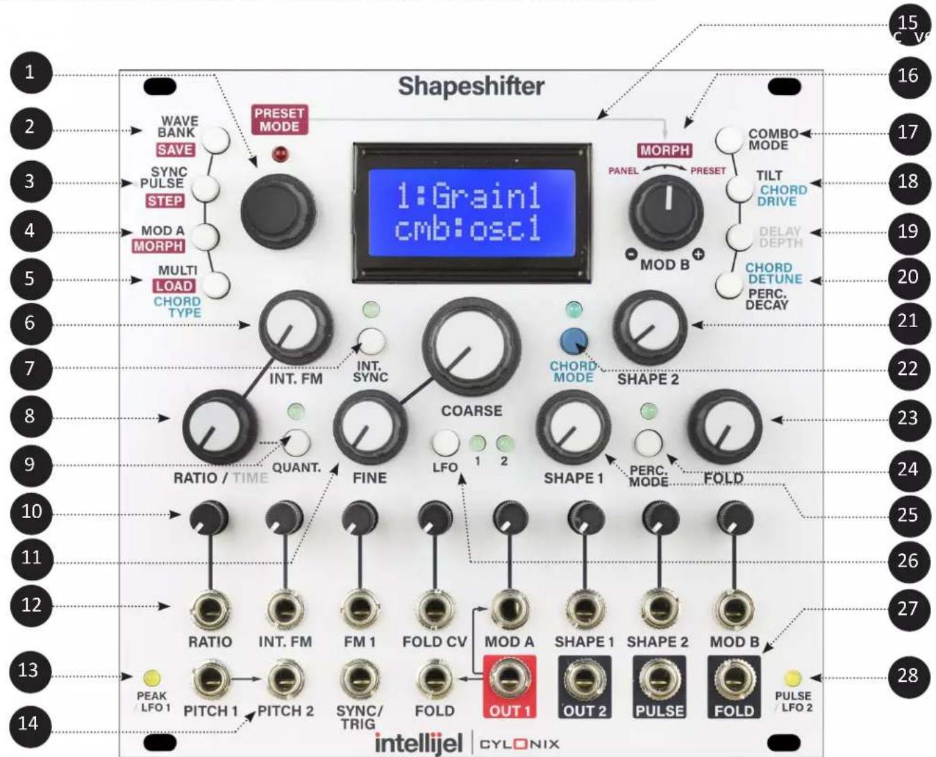
Front Panel Elements (numbers refer to the diagram on the first page)
1 MANUAL DATA INPUT - this is a rotary encoder which is used to enter data in various operation modes. Pushing on the encoder activates a switch which enters and exits the PRESET mode. The red LED above the encoder indicates whether or not the PRESET mode is active. When the LED Is lit the PRESET mode is active.
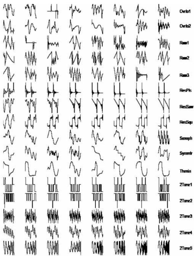
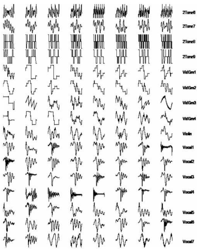
2 WAVE BANK/SAVE BUTTON - this button, when pressed, switches the rotary encoder to entry of the active wave bank for oscillator 1 or 2. Successive presses of the buttons toggles between oscillator 1 and oscillator 2. When bank select is active, the top line of the LCD display will show a descriptive title for the currently selected wave bank. The waves corresponding to each wave bank are depicted in Appendix A. When the module is in PRESET mode (indicated by the illumination of the red LED above the rotary encoder) this button has a different function - that of saving the current front panel control state into the currently selected preset.
3 SYNC/PULSE/STEP BUTTON - this button, when pressed, switches the rotary encoder to selection of the oscillator 1 SYNC mode. A second press leads to setting of the oscillator 2 SYNC mode. A third press of the button switches the rotary encoder to selection of the PULSE output source. When the module is in PRESET mode (indicated by the illumination of the red LED above the rotary encoder) this button has a different function - that of entering the PRESET STEP mode.
4
MODA/MORPH BUTTON - this button, when pressed, switches the rotary encoder to selection of the MODA destination. When pressed a second time, the encoder is used to select whether the OSC2 output modulations the SHAPE1 or TILT parameters.
When the module is in PRESET mode (indicated by the illumination of the red LED above the rotary encoder) this button has a different function - that of entering the MORPH mode.
5 CHORD TYPE/MULTI/LOAD BUTTON - this button, when pressed, switches the rotary encoder to selection of the MULTI setting for oscillator 1. A second press of the button switches the rotary encoder to selection of the MULTI setting for oscillator 1. If CHORD mode is active (as indicated by the illumination of the LED above the CHORD mode button) then a third button press will switch the rotary encoder to selection of the CHORD type.
When the module is in PRESET mode (Indicated by the Illumination of the red LED above the rotary encoder) this button has a different function - that of loading the control settings from the currently selected PRESET.
6 INT. FM POTENTIOMETER - this potentiometer provides an offset that is summed with the external IFM input signal to produce the signal that sets the modulation of oscillator 1's frequency by the output of oscillator 2. The internal FM is computed at the system clock rate of 25 MHz, providing very high-quality aliasing free modulations.
7 INT. SYNC BUTTON - this button toggles the internal sync on and off. When on, as indicated by the illumination of the LED above the button, both oscillators 1 and 2 are synchronized at the start of each cycle of an internal synchronization oscillator running at the same frequency as oscillator 1 (except that the synchronization oscillator is not affected by the FM inputs to oscillator 1). The specific response of the oscillators to the synchronization pulses depends on the SYNC mode setting. Pressing the button twice will cause the LED to flash, and the internal synchronization oscillator will then run at half the frequency of oscillator 1.
Front Panel Elements (continued...)
8 RATIO/TIME POTENTIOMETER - this potentiometer provides an offset to the oscillator 2 RATIO setting. This is summed with the external RATIO input signal. The pitch of oscillator 2 is shifted by an amount proportional to this sum. Oscillator 2's frequency setting is also used to set the delay time for the echo effect, thus the RATIO/TIME potentiometer can be used to alter the delay time.
9 QUANT. BUTTON - this button, when pressed, toggles quantization of the oscillator 2 frequency ratio on and off. When ratio quantization is enabled the pitch of oscillator 2 is tied directly to the pitch of oscillator 1. The external PITCH2 Input is ignored In this situation. There are 16 different quantized ratios available: [1/8, 3/16, 1/4, 5/16, 3/8, 1/2, 5/8, 3/4, 1, 5/4, 3/2, 2, 3, 4, 6, 8]. Pressing the button twice when oscillator 2 is in LFO mode puts the system into a mode where the PITCH2 input becomes a clock input, and the frequency of oscillator 2 follows the frequency of the clock input.
10 MODULATION INPUT ATTENUATORS - these mini-potentiometers (without knobs) serve to adjust the level of the modulation inputs (those from the second row of jacks from the bottom of the front panel).
11 FINE and COARSE POTENTIOMETERS - these two potentiometers provide an offset to the pitch for both oscillators. This offset is summed with the external pitch input signals (PITCH1 and PITCH2), as well as the RATIO signal in the case of oscillator 2, to produce the oscillator pitches.
12 MODULATION INPUT JACKS - the top row of jacks are used to input eight different modulation signals. These signals include:
RATIO: adjusts the ratio of the frequency of oscillator 2 as compared to that of oscillator 1. IFM: sets the level of the internal frequency modulation of oscillator 1 by oscillator 2.
FM 1: audio rate linear frequency modulation of oscillator 1.
FOLD CV: adjusts the amount of waveform folding imposed by the analog wave folder.
MOD A: audio rate modulation input with a number of different modulation targets.
SHAPE 1: modulates the shape of oscillator 1's waveform within the current wavetable bank.
SHAPE 2: modulates the shape of oscillator' 2s waveform within the current wavetable bank.
MOD B: low rate modulation input with a number of different modulation targets.
13 PEAK/LFO 1 LED - this LED indicates whether either of the two audio-rate modulation Inputs, FM 1 and MOD A, have reached the limits of their range, and hence whether clipping of these signals is occurring. If you see the PEAK LED come on, turn down the attenuator for these inputs. When oscillator 1 is operating in LFO mode, this LED no longer signals the presence of peaks, but instead indicates the sign of output 1 (i.e. the LED is illuminated whenever output 1 is positive).
14 INPUT JACKS - the four leftmost jacks in the bottom row are used to input the following signals: PITCH 1: this input sets the pitch of oscillator 1. It has a 1 volt/octave scale factor.
PITCH 2: this input sets the pitch of oscillator 2. It has a 1 volt/octave scale factor. This jack is normalized to the PITCH 1 jack, which means that if no cable is plugged into the PITCH 2 jack, the PITCH 2 input follows the signal input to the PITCH 1 jack.
SYNC: positive-going pulses input to this jack cause the oscillators to be synchronized, according to the current SYNC mode settings. These pulses are also used to trigger the percussive attacks when the module is in PERC mode, and cause stepping of the presets when preset stepping is activated.
FOLD IN: the signal input to this jack is fed to the input of the analog wavefolder circuitry. It is normalized to the OUT 1 jack, so that if no cable is plugged into the FOLD IN jack, the input to the wavefolder is taken from output 1.
Front Panel Elements (continued...)
15 TWO-LINE LCD DISPLAY - the top row of this display is used, in various modes, to show the waveform banks for the two oscillators, the sync mode, the pulse output source, the MODA destination, the MULTI settings, and the chord type. When PRESET mode is active the top row of the display shows the preset number, the preset step mode parameters, and the morph preset. The bottom row of the display is used to show the various MODB parameter settings: the combination mode, oscillator 1 waveform tilt, echo level, chord mode detuning, chord mode overdrive level, and the percussion mode decay time.
16 MOD B/MORPH POTENTIOMETER - this potentiometer provides an offset for the MOD B modulation level. This is summed with the external MOD B Input to provide the overall MOD B modulation level. The potentiometer gives a zero value when at the 12 o'clock setting, and negative offsets when rotated counter-clockwise and positive offsets when clockwise. When a parameter (such as the TILT level) is selected to be a MOD B destination, the lower row of the display will show the current value of the modulation level. When the MORPH mode is enabled while in PRESET mode, the MOD B/MORPH control will set the level of morphing from the panel control settings to the currently selected preset values. Full counter-clockwise gives the panel settings while full clockwise gives the preset settings.
17 COMBO MODE BUTTON - this button, when pressed, switches the rotary encoder to selection of the nonlinear outputs combination modes. The encoder selected mode is displayed on the bottom row of the LCD display. Subsequent presses of the button toggles the MOD B modulation on and off. When the MOD B modulation is enabled the LCD display will change to show the offset to the selected mode.
18 TILT/DRIVE BUTTON - this button, when pressed, switches the rotary encoder to setting of the waveform TILT level for oscillator 1. The TILT parameter setting is displayed on the bottom row of the LCD display. Subsequent presses of the button toggles the MOD B modulation on and off. When the MOD B modulation is enabled the LCD display will change to show the offset to the TILT setting. When CHORD mode is active, the output 1 DRIVE level will be set and displayed instead of the TILT level.
19 DELAY BUTTON - this button, when pressed, switches the rotary encoder to setting of the ECHO level. The setting is displayed on the bottom row of the LCD display. Subsequent presses of the button toggles the MOD B modulation on and off. When the MOD B modulation is enabled the LCD display will change to show the offset to the echo level.
20 DETUNE/DECAY BUTTON - this button, when pressed, switches the rotary encoder to setting of the detuning for oscillator 1 in CHORD mode. The DETUNE parameter is displayed on the bottom row of the LCD display. Subsequent presses of the button toggles the MOD B modulation on and off. When the MOD B modulation is enabled the LCD display will change to show the offset to the DETUNE parameter. When PERC mode is active, the percussive envelope DECAY time will be set and displayed instead of the DETUNE parameter value.
21 SHAPE 2 POTENTIOMETER - this potentiometer selects the waveform for oscillator 2 from the 8 waveforms in the currently selected wave bank. There is a smooth interpolation between the waveforms. This setting is summed with the external SHAPE 2 modulation input to provide the actual selection.
Front Panel Elements (continued...)
22 CHORD MODE BUTTON - this button, when pressed, toggles the CHORD mode on and off. When CHORD mode is active, 8 detuned copies of oscillator 1 are running. These copies are shifted in relative pitch in musical Intervals to produce chords. There are 64 different chords that are available. When the CHORD mode is turned on, the upper row of the display will indicate the currently selected chord type. This selection can be changed with the rotary encoder.
23 FOLD POTENTIOMETER - this potentiometer sets the amount of folding imposed by the waveform folder. As this control is part of the analog waveform folder circuitry its setting is not shown on the LCD display.
24 PERC MODE BUTTON - this button, when pressed, turns the PERCUSSION mode on. When this mode is active output 1 is passed through a digital amplifier whose gain is controlled by a simple envelope. The envelope has a very sharp attack and an exponential decay. The decay rate is determined by the DECAY parameter setting. The envelope is triggered by positive-going pulses received at the external sync input jack. When the button is pressed again, the output will stay high as long as the external sync signal is high. Pressing the button a third time returns the system to normal continuous play.
25 SHAPE 1 POTENTIOMETERS - this potentiometer selects the waveform for oscillator 1 from the 8 waveforms in the currently selected wave bank. There is a smooth interpolation between the waveforms. This setting is summed with the external SHAPE 2 modulation input to provide the actual selection.
26 LFO MODE BUTTON and LFO 1,2 LEDs - this button, when pressed, cycles through the enabling of LFO mode for oscillators 1 and 2. The first button press turns on LFO mode for oscillator 2 only. The second button press turns on LFO mode for oscillator 1 only, the third button press enables LFO mode for both oscillators, and the fourth button presses turns off LFO mode for both oscillators. In LFO mode the pitch of the oscillator is dropped by 7 octaves (frequency is divided by 128). When LFO mode is enabled for oscillator 2 and quantization is off, the pitch of oscillator 2 is no longer affected by the COARSE and FINE knobs. It is only affected by the PITCH 2 Input and the RATIO control and input in this situation.
27 OUTPUT JACKS - the four rightmost jacks in the bottom row are used to output the following signals: OUT1: outputs the oscillator 1 waveform after passing it through the nonlinear combination process and the echo/delay effect. The signal is Internally generated at 25MHz but is downsampled to 98KHz before passing through a Digital to Analog converter.
OUT 2: outputs the oscillator 2 waveform. The signal is Internally generated at 25MHz but is downsampled to 98KHz before passing through a Digital to Analog converter.
PULSE: outputs a two-level signal (0-5V) derived from the oscillator 1 or oscillator 2 waveforms (the specific output depends on the particular PULSE mode selected). FOLD: this is the output of the analog wavefolder.
28 PULSE/LFO 2 LED - this LED indicates whether the PULSE output is high (5 volts) or low (0 volts). When oscillator 2 is operating in LFO mode, this LED no longer displays the PULSE output value, but instead indicates the sign of output 2 (i.e. the LED is illuminated whenever output 2 is positive).
SIMPLIFIED SIGNAL FLOW DIAGRAM
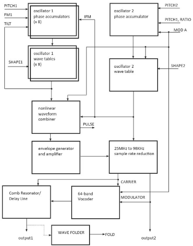
flowchart
graph TD
    A["PITCH1"] --> B["oscillator 1 phase accumulators (x 8)"]
    C["FM1"] --> B
    D["TILT"] --> B
    E["SHAPE1"] --> F["oscillator 1 wave tables (x 8)"]
    B --> F
    F --> G["nonlinear waveform combiner"]
    G --> H["envelope generator and amplifier"]
    H --> I["25MHz to 98KHz sample rate reduction"]
    I --> J["CARRIER"]
    J --> K["64-band Vocoder"]
    K --> L["COMB Resonator/Delay Line"]
    L --> M["WAVE FOLDER"]
    M --> N["FOLD"]
    O["PITCH2"] --> P["oscillator 2 phase accumulator"]
    Q["PITCH1, RATIO"] --> P
    R["MOD A"] --> P
    S["SHAPE2"] --> T["oscillator 2 wave table"]
    U["output2"] --> V["MODULATOR"]
    W["PULSE"] --> G
Oscillator Waveforms
There are two primary oscillators in the Shapeshifter module. These oscillators are based on wavetable synthesis, where the oscillator output is obtained by scanning sequentially through a wavetable memory. Each wave in the wavetable has 512 samples, and each sample is 16 bits. The frequency of the oscillators is determined by their respective PITCH(1,2) inputs, which have a 1volt/octave response. As the oscillator frequency is raised, the oscillator plays through the wavetable more rapidly. Both oscillators can be placed into LFO (low-frequency oscillator) MODE, where the frequency of the oscillator is reduced by 5 octaves (1/32 the value).
The wavetable is divided into 128 banks with 8 waves each, for a total of 1024 different waveshapes. At any given time, the oscillators are reading their waves from one of these banks. The two oscillators can be accessing different wave banks and different waves within the bank. The SHAPE(1,2) control selects which of the 8 waves in a wavebank is currently being played. The SHAPE(1,2) values can be controlled either by the front panel knob or by the external SHAPE(1,2) control voltage inputs. In the latter case, the SHAPE(1,2) knobs act as an offset to the control voltage inputs.
The SHAPE1 parameter can also be modulated by the OSC2 output. To enable this, press the MODA button twice, to bring up the "2mod" menu display. Turn the rotary encoder until the top line of the display reads "'2mod SH1''. To disable this effect, turn the encoder so that the display reads "2mod OFF". This effect is useful when OSC2 is set to LFO mode and SYNC2 mode is set to 1shot. In this way OSC2 acts as a SHAPE1 parameter envelope.
When the 128th entry is selected, the wave bank is controlled by the MODB input. This mode is indicated by the presence of a * symbol in the display.
Oscillator 2 Pitch Setting
In Normal operation, when QUANT is turned off (the QUANT LED is not lit) the frequency of oscillator 2 is set by the voltage at the PITCH 2 input. This is normalled (connected) to the PITCH 1 input when there is no cable plugged into the PITCH 2 jack. In this situation (when QUANT is off) the RATIO knob and control voltage acts as an offset to the PITCH 2 voltage.
When the QUANT button is pressed once, so that the QUANT LED is lit, the frequency of oscillator 2 is set to a integer multiple or fraction of the frequency of oscillator 1. The external PITCH2 input is ignored in this situation. This ratio is controlled by the RATIO/TIME knob and control voltage. The ratio is quantized to one of the following 16 values: [1/8, 3/16, 1/4, 5/16, 3/8, 1/2, 5/8, 3/4, 1, 5/4, 3/2, 2, 3, 4, 6, 8].
When the QUANT button is pressed twice, so that the QUANT LED flashes, the frequency of oscillator 2 follows the frequency of a clock signal present at the PITCH 2 Input Jack. If no suitable clock signal is present, the frequency will be very low. The actual frequency of oscillator 2 will be a multiple/fraction of the frequency of the clock signal, and the ratio is set by the RATIO knob and control voltage input. This ratio is quantized to one of the following 15 values: [1/24, 1/16, 1/12, 1/8, 1/6, 1/4, 1/3, 1/2, 1, 2, 3, 4, 6, 8, 12]. Note that in the clocked OSC2 mode the LFO setting is ignored. The clocked OSC2 operation mode is good for implementing clocked LFOs and clocked envelopes (using OSC2 as an envelope for OSC1 in the "ring" COMBO mode). It is also useful for making clocked delay lines when the DELAY value is turned up.
Nonlinear Waveform Combination Modes
The outputs of the two oscillators are sent through a nonlinear combination process before going to the echo/delay effect and then onto output 1. The combination process allows the generation of complex timbres and interactions between the two oscillators, as shown in the figures on the next two pages.
Press the COMBO MODE button to activate the rotary encoder for selection of the combination mode. The selected combination mode will be shown in the bottom row of the LCD display. The COMBO MODE parameter can also be modulated by the MOD B Input, which is activated with a second press of the COMBO MODE button. When MOD B modulation is active the lower row of the LCD display will change to show both the nominal setting and the offset provided by the MOD B modulation.
There are 8 different combination modes that can be selected:
cmb:osc1 - In this mode there is no nonlinear combination. The output of oscillator 1 is taken as is.
cmb:ring - in this mode the outputs of oscillator 1 and oscillator 2 are multiplied, equivalent to the well-known ring modulation effect.
cmb: min - in this mode either the output of oscillator 1 or the output of oscillator 2 is chosen, depending on which one has the lower value.
cmb:pong - In this mode the output of oscillator 1 is chosen if it has a positive value, otherwise the output of oscillator 2 is chosen if it has a negative value. If neither of these conditions holds, then the output is set to 0.
cmb:inlv - in this mode the digital bits representing the two oscillator waveforms are interleaved to provide the output of the combination process. The most significant bit of oscillator 1 is used as the most significant bit of the output, the 2nd most significant bit of oscillator 2 is used as the 2nd most significant bit of the output, and so forth, alternating between taking bits from oscillator 1 and 2.
cmb: and - in this mode the digital bits representing the two oscillator waveforms are combined using the logical AND operation (the AND operation produces a 1 bit when both the input bits are 1, otherwise it produces a 0 result).
cmb: xor - in this mode the digital bits representing the two oscillator waveforms are combined using the logical XOR operation (the XOR operation produces a 0 bit when the input bits have the same value, otherwise when the bits have different values it produces a 1 result).
cmb:gLcH - in this mode each bit of the output of the combination process is set to 1 whenever the respective bits of oscillator 1 and 2 both become 1, and is set to 0 whenever the respective bits of oscillator 1 and 2 both become 0. Otherwise the bits hold their value constant. Whenever the 2nd most significant bit of the combination goes from 0 to 1, the phase of oscillator 1 is 'bumped', or offset, by a step of 1/4 cycle (or 90 degrees of phase) and the phase of oscillator 2 is bumped by a step of 1/8 cycle (or 45 degrees of phase). The overall effect of this rather complicated combination is to provide a noisy and glitchy sound.
RING
MIN
PONG
INLV

line
| Time Point | Series 1 | Series 2 | Series 3 | Series 4 | | ---------- | -------- | -------- | -------- | -------- | | 0 | 0.0 | 0.0 | 0.0 | 0.0 | | 1 | 0.5 | 0.3 | 0.7 | 0.2 | | 2 | 0.2 | 0.6 | 0.4 | 0.8 | | 3 | 0.8 | 0.1 | 0.9 | 0.3 | | 4 | 0.3 | 0.7 | 0.2 | 0.6 | | 5 | 0.6 | 0.4 | 0.8 | 0.1 | | 6 | 0.1 | 0.5 | 0.3 | 0.7 | | 7 | 0.7 | 0.2 | 0.6 | 0.4 | | 8 | 0.4 | 0.8 | 0.1 | 0.9 | | 9 | 0.9 | 0.3 | 0.7 | 0.2 | | 10 | 0.2 | 0.6 | 0.4 | 0.8 | | 11 | 0.7 | 0.1 | 0.5 | 0.3 | | 12 | 0.3 | 0.7 | 0.9 | 0.6 | | 13 | 0.6 | 0.4 | 0.2 | 0.7 | | 14 | 0.1 | 0.8 | 0.8 | 0.1 | | 15 | 0.8 | 0.2 | 0.3 | 0.9 | | 16 | 0.4 | 0.6 | 0.6 | 0.2 | | 17 | 0.9 | 0.3 | 0.1 | 0.7 | | 18 | 0.2 | 0.7 | 0.7 | 0.4 | | 19 | 0.7 | 0.1 | 0.4 | 0.8 | | 20 | 0.3 | 0.8 | 0.9 | 0.2 | | 21 | 0.6 | 0.4 | 0.2 | 0.7 | | 22 | 0.1 | 0.5 | 0.6 | 0.3 | | 23 | 0.8 | 0.2 | 0.1 | 0.9 | | 24 | 0.4 | 0.7 | 0.8 | 0.1 | | 25 | 0.9 | 0.3 | 0.3 | 0.7 | | 26 | 0.2 | 0.6 | 0.7 | 0.4 | | 27 | 0.7 | 0.1 | 0.5 | 0.8 | | 28 | 0.3 | 0.8 | 0.9 | 0.2 | | 29 | 0.6 | 0.4 | 0.2 | 0.7 | | 30 | 0.1 | 0.5 | 0.7 | 0.3 | | 31 | 0.8 | 0.2 | 0.4 | 0.9 | | Peak | - | - | - | - | | Final | - | - | - | - |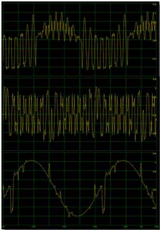
Examples of the output of the nonlinear waveform combination process in the different waveform combination modes (the osc1 mode is not shown). The oscillator 1 and oscillator 2 waveforms are both sine waves, with the frequency of oscillator 2 set to about 16 times that of oscillator 1.
Oscillator SYNC Modes
The oscillators can be reset, or synchronized, whenever a synchronization event occurs. A synchronization event happens whenever the voltage at the SYNC input jack rises above about 0.2 volts, and also whenever the phase of the Internal synchronization oscillator passes zero when the INT. SYNC mode is enabled (by pressing the INT SYNC button). The synchronization oscillator runs at either at the same (INT SYNC LED is steady on after the first press of the INT SYNC button), or half (INT SYNC LED is flashing, after pressing the INT SYNC button twice) of the nominal frequency as oscillator 1.
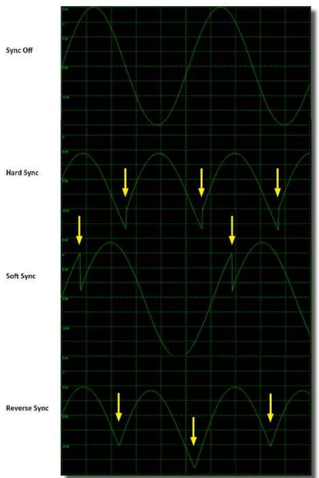
The specific behaviour of the oscillators in response to a synchronization event depends on the currently selected SYNC mode, as described below and shown in the figure on the next pages.
Press the SYNC/PULSE/STEP button to activate the rotary encoder for selection of the SYNC mode. The selected SYNC mode for oscillator 1 will be shown in the upper row of the LCD display. Press the SYNC button again to select the SYNC mode for oscillator 2.
There are 9 different SYNC modes that can be selected:
Hard - in this mode the phases of the oscillator is reset to zero when a synchronization event occurs. This is most common type of synchronization effect found in other oscillator modules.
Soft - In this mode the phase the oscillator is reset to zero when a synchronization event occurs but only when the oscillator waveform is in the first quarter of its cycle (i.e. where the phase is between 0 and 90 degrees). Thus the oscillators might not be reset on every synchronization event. This gives a somewhat noisier and more erratic sound than hardsync.
Rev - in this mode the direction of the waveform is reversed when a synchronization event occurs. For example, a rising sawtooth waveform will become a falling sawtooth waveform. This tends to provide a rather smooth sound, useful for basses, especially when INT SYNC is enabled.
Hold - in this mode the output of the oscillator switches between being held constant (freeze effect) or running free on each synchronization event. This is useful to provide choppy gating effects.
1shot - The oscillator will go through one complete cycle on each synchronization event. This is particularly useful when using oscillator 2 as an LFO or an Envelope (e.g. in "RING" combo mode).
Bump - in this mode the phase of the oscillator is 'bumped', or offset, (by 1/4th of a cycle (90 degrees) for oscillator 1 and 1/8th of a cycle (45 degrees) for oscillator 2) on a synchronization event.
2=1 Sync - this mode operates in the same way as HardSync mode, except that whenever the output of oscillator 1 is equal to the output of oscillator 2 an additional synchronization event is created that is sent to oscillator 2 only. The typical result is to create 'chirps' in oscillator 2.
1=2 Sync - this mode is similar to 2=1 Synch mode except that the additional synchronization event is sent to oscillator 1 only. In this mode the 'chirps' are created in oscillator 1.
Off - In this mode the synchronization events have no effect on the oscillator. It can be useful when the SYNC input is used to step the presets in PRESET STEP mode to avoid the transient that might otherwise occur, and also in CHORD mode to prevent the phase alignment of the 8 oscillators (unless you want that effect!).
line
| Sync State | Value | | -------------- | ----- | | Sync Off | High | | Hard Sync | Low | | Soft Sync | Medium| | Reverse Sync | Low |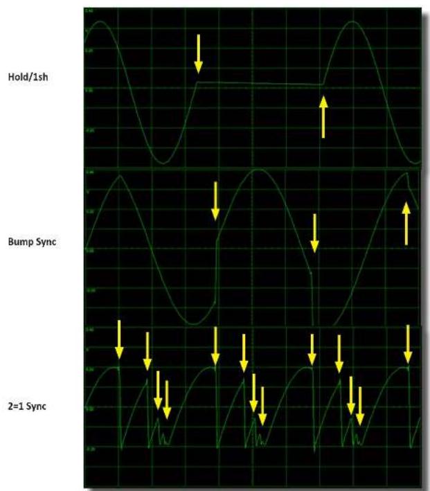
line
| Signal Type | Value | |-------------|-------| | Hold/1sh | High | | Bump Sync | Low | | 2=1 Sync | Low |Examples of the oscillator 2 output in the different sync modes, with int. sync turned on. Oscillator 2 is set to sine wave. In the 1=2 Sync mode (not shown) the output of oscillator 2 would look the same as in the Hard Sync mode, but the output of oscillator 1 in this case would look similar to the output shown for oscillator 2 in the 2=1 Sync mode. The yellow arrows indicate the occurrence of synchronization events (which can come from either the external SYNC input or from the internal sync).
PULSE Source Modes
The lower row of jacks on the front panel includes a PULSE output. This output is a two-level signal, either at 0 volts or 5 volts. This signal is derived from the outputs of oscillators 1 and 2 in various ways.
Press the SYNC/PULSE/STEP button two times to activate the rotary encoder for selection of the PULSE source. The selected PULSE source will be shown in the upper row of the LCD display.
There are 16 different PULSE source modes that can be selected:
+01 or +02 : in this mode the PULSE output is high (5 volts) when the oscillator's (1 or 2) output is positive. Otherwise it is low (0 volts).
EOC: in this mode the PULSE output goes high when the output 1 envelope is high. During normal operation (PERC MODE LED is off) this will always be high. When PERC mode is active, this output will be low during the decay phase of the percussive envelope and will go high at the end of the envelope cycle. This could be used to trigger other events in a modular system.
-02: in this mode the PULSE output is high (5 volts) when oscillator 2's output is negative. Otherwise it is low (0 volts).
OR : in this mode the PULSE output is high when either oscillator 1's output is positive or oscillator 2's output is positive.
AND: in this mode the PULSE output is high when both oscillator 1's output is positive and oscillator 2's output is positive.
XOR : in this mode the PULSE output is low when oscillator 1's and oscillator 2's outputs are both positive or both negative. Otherwise the output is high.
gLcH : in this mode the PULSE output is equal to the sign of the output of the nonlinear waveform combination process as when running in gLcH mode. This mode is available even when the combination mode is set to something other than gLcH. This mode can be useful in generating noisy and glitchy triggers.
sq1 or sq2 : in this mode a square wave appears on the PULSE output with a frequency equal to that of the oscillator (1 or 2).
pwm1 or pwm2 : In this mode a pulse wave appears on the PULSE output with a frequency equal to that of the oscillator {1 or 2} and with a variable pulse width that is controlled by the SHAPE {1 or 2} signal.
1>2/1<2 : in this mode the PULSE output is high whenever the oscillator 1 output is greater than (less than) that of oscillator 2.
RND1 or RND2 : in this mode the PULSE output changes randomly on the start of every cycle of oscillator 1 (or 2). RND2 is useful when oscillator 2 is in LFO mode for generating random triggers. Feed it back into the SYNC input!
MOD A Destinations
The MOD A input located in the top row of jacks is converted to digital form at a high sampling rate (98 KHz). This digitized signal can be inserted into the system at a number of points, providing different capabilities for the module. This Input is AC-coupled, meaning that it is not sensitive to DC (or very low frequency) values.
Press the MOD A/MORPH button to activate the rotary encoder for specifying the destination of the MOD A signal. The selected destination will be shown in the upper row of the LCD display. There are 10 different destinations for the MOD A input that can be selected:
Phase2 - the MOD A signal is used to modulate the PHASE of oscillator 2.
Combo 2 - the MOD A signal is fed into the nonlinear combination process in place of the oscillator 2 output. This allows an external signal to be combined with oscillator 1's output (for example, one could do RING MODULATION or XOR-ing of oscillator 1's waveform with an external audio signal).
Shaper 2 - the MOD A signal is used to address the wavetable for oscillator 2. In this situation the PITCH 2 and RATIO signals have no effect, since the phase accumulator for oscillator 2 is disconnected from the circuit. Instead, the MOD A signal is driving the wave table addressing. If one feeds in a sawtooth waveform from another oscillator module, the results would be similar to using the internal oscillator 2, except that the pitch is now being controlled by the external source. But one can feed in waveforms other than sawtooths, in which case the effect will be similar to waveshaper. or distortion effects, for example.
Voc MOD - the MOD A signal is used as the MODULATION signal for the 64-band vocoder. The output of the nonlinear waveform combiner is used as the vocoder's CARRIER signal. The vocoder consists of two banks of 64 bandpass filters that covers the frequency spectrum from roughly 15Hz to 15,000Hz. One filter bank is used to measure the energy in the MODULATION signal in each of the 64 frequency channels, while the other is used to filter the CARRIER signal. The individual energy levels of each channel for the MODULATION signal are multiplied by the individual channel outputs of the CARRIER signal filter bank. These 64 products are summed together to produce the single vocoder output signal. The effect is to map the spectrum of the MODULATOR onto that of the CARRIER. This can produce 'robotic' vocal sounds when the carrier frequency is held constant or melodic singing sounds when the CARRIER pitch is varied. For best results, the CARRIER signal should use harmonic-rich waveforms such as sawtooth or pulse waves.
Phase1 - the MOD A signal is used to modulate the PHASE of oscillator 1.
Combo 1 - the MOD A signal is fed into the nonlinear combination process instead of oscillator 1's output.
Shaper 1 - the MOD A signal is used to address the wavetable for oscillator 1. In CHORD mode the MOD A signal only affects the root oscillator. The other seven are unaffected.
Voc CARR - the MOD A signal is used as the CARRIER signal for the vocoder.
Sync 2 - the MOD A signal is used as the external sync signal for oscillator 2. In this way oscillators 1 and 2 can be synced to different signals.
PrstStep - the MOD A signal is used as to trigger stepping in PRESET STEP mode. This allows the SYNC input to be used for PERC MODE triggering or external sync signals while doing Preset stepping.
CHORD MODE
When CHORD MODE is activated, by pressing the CHORD MODE button, the LED above the button will light up. More importantly, when CHORD MODE is active, oscillator 1 will be split into 8 separate oscillators, each outputting the same waveform, but with different frequencies. This allows chords to be played when the frequencies are chosen to be at musical intervals, and provides a deep, rich, sound when the frequencies are chosen to be the same (i.e. a UNISON chord), but with slight variations in tuning between them.
The amount of detuning between the 8 oscillators can be adjusted by pressing the DETUNE/DECAY button (as long as PERC. MODE is not active). When this is done, the lower line of the LCD display will show the current detuning value, expressed as a number from 0 to 99. This value can be changed with the rotary encoder. A larger number means a greater detuning. The detuning is an offset to the oscillator frequencies rather than a scaling, meaning that the effect for a given detuning is less at higher pitches. So you may want to increase the detuning amount when playing mainly high notes and lower it when playing mainly low notes. The detuning parameter can also be modulated by the MOD B input, which is activated with a second press of the DETUNE/DECAY button. When MOD B modulation is active the lower row of the LCD display will change to show both the nominal setting and the offset provided by the MOD B modulation.
When CHORD MODE is first activated, the top line of the LCD display will change to showing the currently selected chord type. This can be selected using the rotary encoder. There are 64 different chord types that can be chosen. The following table shows the label for each type shown in the LCD display, along with the interval in semitones assigned to each of the 8 oscillators (0 is the root note). Negative numbers indicate suboctave intervals (pitches below the root note). When the rotary encoder sets the Chord Type to the 64th (last) setting, the chord type is actually controlled by the MODB signal. This allows the Chord Type to be set by control voltage from an external sequencer, for example. The use of MODB to select the chord type is indicated by a “*” symbol in the display.
| CH:uniso | 0 | 0 | 0 | 0 | 0 | 0 | 0 | 0 | (unison) |
| CH:m2nd | 0 | 0 | 0 | 0 | 1 | 1 | 1 | 1 | (minor 2nd interval) |
| CH:M2nd | 0 | 0 | 0 | 0 | 2 | 2 | 2 | 2 | (major 2nd interval) |
| CH:m3rd | 0 | 0 | 0 | 0 | 3 | 3 | 3 | 3 | (minor 3rd interval) |
| CH:M3rd | 0 | 0 | 0 | 0 | 4 | 4 | 4 | 4 | (major 3rd interval) |
| CH:4th | 0 | 0 | 0 | 0 | 5 | 5 | 5 | 5 | (4th interval) |
| CH:trito | 0 | 0 | 0 | 0 | 6 | 6 | 6 | 6 | (tritone interval) |
| CH:5th | 0 | 0 | 0 | 0 | 7 | 7 | 7 | 7 | (5th interval) |
| CH:aug5 | 0 | 0 | 0 | 0 | 8 | 8 | 8 | 8 | (augmented 5th interval) |
| CH:6th | 0 | 0 | 0 | 0 | 9 | 9 | 9 | 9 | (6th interval) |
| CH:m7th | 0 | 0 | 0 | 0 | 10 | 10 | 10 | 10 | (minor 7th interval) |
| CH:M7th | 0 | 0 | 0 | 0 | 11 | 11 | 11 | 11 | (major 7th interval) |
| CH:octav | 0 | 0 | 0 | 0 | 12 | 12 | 12 | 12 | (octave interval) |
| CH:suboc | 0 | 0 | 0 | 0 | -12 | -12 | -12 | -12 | (suboctave) |
| CH:2oct | 0 | 12 | 24 | 0 | 12 | 24 | 12 | ( octave + 2octave) | |
| CH:minor | 0 | 3 | 7 | 0 | 3 | 7 | 0 | 3 | (minor triad) |
| CH:minl1 | 12 | 3 | 7 | 12 | 3 | 7 | 12 | 3 ( minor triad 1st inversion) | |
| CH:minl2 | 12 | 15 | 7 | 12 | 15 | 7 | 12 | 15 ( minor triad 2nd inversion) | |
| CH:major | 0 | 4 | 7 | 0 | 4 | 7 | 0 | 4 | (major triad) |
| CH:maj1 | 12 | 4 | 7 | 12 | 4 | 7 | 12 | 4 ( major triad 1st inversion) | |
| CH:maj2 | 12 | 16 | 7 | 12 | 16 | 7 | 12 | 16 ( major triad 2nd inversion) | |
| CH:sus | 0 | 5 | 7 | 0 | 5 | 7 | 5 | 7 (suspended triad) |
CHORD MODE (continued...)
| CH: aug | 0 | 4 | 8 | 0 | 4 | 8 | 0 | 8 | (augmented triad) |
| CH: dim | 0 | 3 | 6 | 0 | 3 | 6 | 0 | 6 | (diminished triad) |
| CH: maj6 | 0 | 4 | 7 | 9 | 0 | 4 | 7 | 9 | (major 6th) |
| CH: maj7 | 0 | 4 | 7 | 11 | 0 | 4 | 7 | 11 | (major 7th) |
| CH:7M1st 12 | 4 | 7 | 11 | 12 | 4 | 7 | 11 | (major 7th 1st inversion) | |
| CH:7M2nd | 12 | 16 | 7 | 11 | 12 | 16 | 7 | 11 | (major 7th 2nd inversion) |
| CH:7M3rd | 12 | 16 | 19 | 11 | 12 | 16 | 19 | 11 | (major 7th 3rd inversion) |
| CH: dom | 0 | 4 | 7 | 10 | 0 | 4 | 7 | 10 | (dominant 7th) |
| CH:7D1st | 12 | 4 | 7 | 10 | 12 | 4 | 7 | 10 | (dominant 7th 1st inversion) |
| CH:7D2nd 12 | 16 | 7 | 10 | 12 | 16 | 7 | 10 | (dominant 7th 2nd inversion) | |
| CH:7D3rd | 12 | 16 | 19 | 10 | 12 | 16 | 19 | 10 | (dominant 7th 3rd inversion) |
| CH: min7 | 0 | 3 | 7 | 10 | 0 | 3 | 7 | 10 | (minor 7th) |
| CH:7m1st | 12 | 3 | 7 | 10 | 12 | 3 | 7 | 10 | (minor 7th 1st inversion) |
| CH:7m2nd | 12 | 15 | 7 | 10 | 12 | 15 | 7 | 10 | (minor 7th 2nd inversion) |
| CH:7m3rd 12 | 15 | 19 | 10 | 12 | 15 | 19 | 10 | (minor 7th 3rd inversion) | |
| CH:hdim7 0 | 3 | 6 | 10 | 0 | 3 | 6 | 10 | (half diminished 7th) | |
| CH:7h1st | 12 | 3 | 6 | 10 | 12 | 3 | 6 | 10 | (half diminished 7th 1st inversion) |
| CH:7h2nd 12 | 15 | 6 | 10 | 12 | 15 | 6 | 10 | (half diminished 7th 2nd inversion) | |
| CH:7h3rd 12 | 15 | 18 | 10 | 12 | 15 | 18 | 10 | (half diminished 7th 3rd inversion) | |
| CH: dim7 | 0 | 3 | 6 | 9 | 0 | 3 | 6 | 9 | (diminished 7th) |
| CH:7d1st | 12 | 3 | 6 | 9 | 12 | 3 | 6 | 9 | (diminished 7th 1st inversion) |
| CH:7d2nd 12 | 15 | 6 | 9 | 12 | 15 | 6 | 9 | (diminished 7th 2nd inversion) | |
| CH:7d3rd 12 | 15 | 18 | 9 | 12 | 15 | 18 | 9 | (diminished 7th 3rd inversion) | |
| CH:7sus | 0 | 5 | 7 | 10 | 0 | 5 | 7 | 10 | (suspended 7th) |
| CH:7s1st | 12 | 5 | 7 | 10 | 12 | 5 | 7 | 10 | (suspended 7th 1st inversion) |
| CH:7s2nd 12 | 17 | 7 | 10 | 12 | 17 | 7 | 10 | (suspended 7th 2nd inversion) | |
| CH:7s3rd | 12 | 17 | 19 | 10 | 12 | 17 | 19 | 10 | (suspended 7th 3rd inversion) |
| CH:D9th | 0 | 4 | 7 | 10 | 14 | 14 | 7 | 10 | (dominant 9th) |
| CH:9D2nd 12 | 16 | 7 | 10 | 14 | 14 | 7 | 10 | (dominant 9th 2nd inversion) | |
| CH:Dm9th | 0 | 4 | 7 | 10 | 13 | 13 | 7 | 10 | (dominant minor 9th) |
| CH:Dm9-2 | 12 | 16 | 7 | 10 | 13 | 13 | 7 | 10 | (dominant minor 9th 2nd inversion) |
| CH: maj9 | 0 | 4 | 7 | 11 | 14 | 14 | 7 | 11 | (major 9th) |
| CH:9M2nd | 12 | 16 | 7 | 11 | 14 | 14 | 7 | 11 | (major 9th 2nd inversion) |
| CH: min9 | 0 | 3 | 7 | 10 | 14 | 14 | 7 | 10 | (minor 9th) |
| CH:9m2nd | 12 | 15 | 7 | 10 | 14 | 14 | 7 | 10 | (minor 9th 2nd inversion) |
| CH: M6/9 | 0 | 4 | 7 | 9 | 14 | 4 | 7 | 9 | (major 6/9) |
| CH: m6/9 0 | 3 | 7 | 9 | 14 | 3 | 7 | 9 | (minor 6/9) | |
| CH: 9b5 0 | 4 | 6 | 10 | 14 | 14 | 6 | 10 | (9th flat 5th) | |
| CH: 9#5 | 0 | 4 | 8 | 10 | 14 | 14 | 8 | 10 | (9th sharp 5th) |
| CH:D11th | 0 | 10 | 7 | 10 | 14 | 18 | 7 | 18 | (dominant 11th) |
| CH:m11th | 0 | 3 | 7 | 10 | 14 | 17 | 14 | 17 | (minor 11th) |
| CH*(various) (the chord type is selected by the MODB voltage level) | |||||||||
The tuning of the chords can be switched between Just Intonation and Equal Temperament. This is accessed by pressing the Chord Type/Multi/Load button while Chord Mode is active. Use the rotary encoder to switch between the two tuning methods.
MULTI SETTINGS
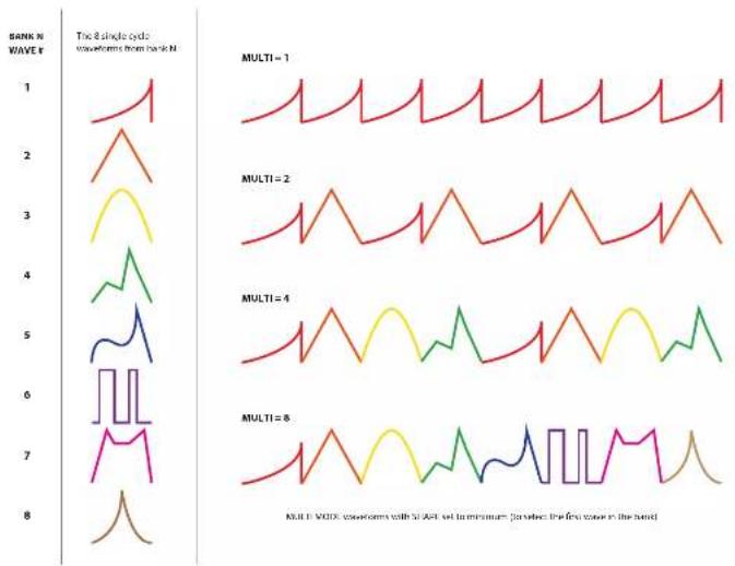
The MULTI setting modifies the way in which the wavetables are read. Normally the wavetables are read in 512 sample chunks, called 'waves'. These waves are shown in Appendix A. In the MULTI modes successive waves are strung together to provide more complex waveforms. There are four different MULTI modes, corresponding to 1 wave (normal operation with 512-sample waveforms), 2 waves strung together (1024-sample waveforms), 4 waves strung together (2048-sample waveforms), and 8 waves strung together (4096-sample waveforms).
To adjust the MULTI settings for oscillator 1, press the CHORD TYPE/MULTI/LOAD button. If CHORD mode is off the LCD display will show "Multi1: N", where N is the current multi setting for oscillator 1. The setting can then be adjusted with the rotary encoder to a value of 1, 2, 4, or 8. The number (1,2,4,8) indicates how many waves are strung together. To change the multi setting for oscillator 2, press the CHORD TYPE/MULTI/LOAD button once more. The LCD display will now show "Multi2: N", where N is the current multi setting for oscillator 1. If CHORD mode is off pressing the button again will take you back to setting for oscillator 1, otherwise it will take you to setting of the CHORD TYPE.
The figure below illustrates how the waves in a bank are strung together to create the waveforms produced by the four different MULTI settings.
line
| Time (s) | MULTI = 1 | MULTI = 2 | MULTI = 4 | MULTI = 8 | |----------|-----------|-----------|-----------|-----------| | 1 | High | Medium | Low | Low | | 2 | Medium | Medium | Low | Low | | 3 | Medium | Medium | Low | Low | | 4 | Medium | Medium | Low | Low | | 5 | Medium | Medium | Low | Low | | 6 | Medium | Medium | Low | Low | | 7 | Medium | Medium | Low | Low | | 8 | Low | Low | Low | Low |TILT FUNCTION
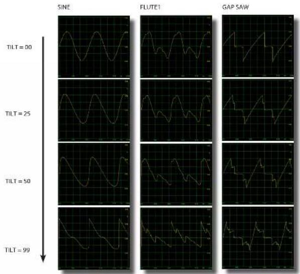
The TILT function phase modulates oscillator 1 with its own output. This results in a self-feedback loop which has the effect of 'tilting' the waveform, as shown in the diagram below. The amount of feedback, and hence the amount of tilting, is set by the TILT parameter. At large values of the TILT parameter the waveform may start to become distorted, and even chaotic.
To set the nominal value of the TILT parameter, press the TILT/DRIVE button. The TILT parameter value can then be adjusted with the rotary encoder and will be shown in the bottom row of the LCD display.
The TILT parameter can also be modulated by the MOD B Input, which is activated with a second press of the TILT/DRIVE button. When MOD B modulation is active the lower row of the LCD display will change to show both the nominal setting and the offset provided by the MOD B modulation.
The TILT parameter can also be modulated by the OSC2 output. To enable this, press the MODA button twice, to bring up the "2mod" menu display. Turn the rotary encoder until the top line of the display reads "2mod TILT". To disable this effect, turn the encoder so that the display reads "2mod OFF". This effect is useful when OSC2 is set to LFO mode and SYNC2 mode is set to 1shot. In this way OSC2 acts as a TILT parameter envelope.
line
| TILT | SINE | FLUTE1 | GAP SAW | |------|------|--------|---------| | 00 | | | | | 25 | | | | | 50 | | | | | 99 | | | |DRIVE FUNCTION
The DRIVE function is operational only when CHORD MODE is active. It applies a variable amount of gain (between 1 and 3) to output1, followed by a cubic saturation process. The purpose of this function is to compensate somewhat for the loss of amplitude experienced due to phase cancellation of the multiple waveforms when in CHORD MODE. The saturation keeps the peak amplitude within limits, and provides a nice soft rolloff of the peaks for most waveforms. In some cases the result may sound distorted at high DRIVE levels.
To set the nominal value of the DRIVE parameter, press the TILT/DRIVE button. If CHORD MODE is active, the DRIVE parameter value can then be adjusted with the rotary encoder and will be shown in the bottom row of the LCD display. The DRIVE parameter can also be modulated by the MOD B Input, which is activated with a second press of the TILT/DRIVE button. When MOD B modulation is active the lower row of the LCD display will change to show both the nominal setting and the offset provided by the MOD B modulation.
DELAY FUNCTION
The output of the nonlinear waveform combiner, after going through the envelope amplifier, is passed through a simple comb resonator/delay line. For short delay times this acts as a resonator, and at long delay times it provides an echo effect. The DELAY parameter sets the amount of feedback from the output of the delay line back to its input, and also sets the wet/dry mix of the input and delayed signals. As the DELAY parameter increases, the resonator depth, or the echo regeneration increases. At the same time the wet/dry ratio increases. This is needed to prevent saturation or clipping at higher feedback levels, and means that the level of the input signal gets lower and lower as the DELAY parameter increases. At the maximum DELAY setting the feedback is 100% and the input is 0% and the delayed signal will be infinitely repeated (a hold or freeze effect). This can be used in performances to provide overdubbing or looping effects. To do this one quickly changes the DELAY parameter (using the MOD B knob as described in the next paragraph) to 0, plays some material, then quickly changes the DELAY parameter to 99 to hold and repeat the material just played.
To set the nominal value of the DELAY parameter, press the DELAY button. The DELAY parameter value can then be adjusted with the rotary encoder and will be shown in the bottom row of the LCD display (on the display it is labeled as echo rather than delay). The DELAY parameter can also be modulated by the MOD B Input, which is activated with a second press of the DELAY button. When MOD B modulation is active the lower row of the LCD display will change to show both the nominal setting and the offset provided by the MOD B modulation.
The DELAY parameter does not specify the delay time, however. The delay time is set by the period of oscillator 2. This permits synchronized LFO echo effects when oscillator 2 is in LFO mode, and produces pitch synchronous resonator effects when oscillator 2's pitch follows that of oscillator 1 (as when QUANT is turned on). The signal tracking the period of oscillator 2 is passed through a slew-rate limiter (low pass filter or smoother) before using it to compute the delay time. This causes a pitch shifting when the pitch of oscillator 2 changes. At long delay times (oscillator 2 in LFO mode) this produces long gliding pitch shifts, while at short delay times (resonator effect) this slew produces flanging effects.
Note that when the QUANT led is flashing the delay time will be equal to the period of a clock signal fed into the PITCH2 Input. This allows for clock-synced delay or resonator effects.
PERCUSSION MODE
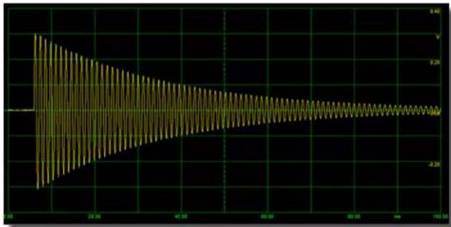
Percussion Mode is turned on and off by pressing the PERC. MODE button. When Percussion Mode is active, as indicated by the illumination of the LED directly above the PERC. MODE button, the output of the nonlinear wave combiner is passed through an amplifier whose gain is modulated by an exponential envelope. This envelope is triggered by a positive-going pulse on the SYNC input jack. The attack phase of the envelope is very fast (less than 1 msec), and there is no sustain phase. The exponential decay begins immediately with a time constant that is set by the DECAY TIME parameter. When Percussion Mode is active, pressing the DETUNE/DECAY button will allow the DECAY TIME parameter to be set with the rotary encoder and its value will be shown in the bottom row of the LCD display. The DECAY TIME parameter can also be modulated by the MOD B Input, which is activated with a second press of the DETUNE/DECAY button. When MOD B modulation is active the lower row of the LCD display will change to show both the nominal setting and the offset provided by the MOD B modulation.
The minimum decay time is about 2msec (to half peak amplitude) and the maximum is about 10 seconds.
When the PERC. MODE button is pressed a second time, the system will activate GATE mode and the LED will flash. In this mode the SYNC input acts as a gate for the envelope. When the SYNC Input goes high the envelope will jump immediately to its maximum value, and will remain there as long as the SYNC input is high. When the SYNC input goes low the envelope will begin to decay at the rate set by the DECAY TIME parameter.
line
| Time | Value | |------|-------| | 0 | 4.5 | | 10 | 3.8 | | 20 | 3.2 | | 30 | 2.8 | | 40 | 2.5 | | 50 | 2.3 | | 60 | 2.2 | | 70 | 2.1 | | 80 | 2.0 | | 90 | 1.9 | | 100 | 1.8 | | 110 | 1.7 | | 120 | 1.6 | | 130 | 1.5 |The output in PERC. MODE when the DECAY TIME parameter is set to 30, acting on a 1KHz sine wave. The time axis shows a period of 100msec.
WAVE FOLDER
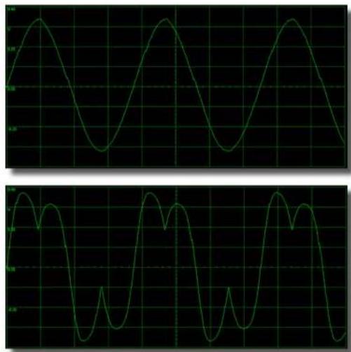
The SHAPESHIFTER module includes a fully analog wave folding circuit. This circuit is based on the one used in the Intellijel μFold II module. Its input comes from the FOLD jack on the bottom row of the front panel. This jack is normalized to the OUT 1 jack meaning that when there is no cable plugged into the FOLD jack, the signal at OUT 1 is fed into the wave folder's input. Inserting a cable into the FOLD jack will break this normalized connection and the wave folder input will be taken from whatever is connected to the cable. This allows an external signal to be acted on by the wave folder.
The action of the wave folder circuit is to bend or fold the input waveform back on itself. This generates harmonics brightening the sound. The amount of folding is set by the position of the FOLD knob and by the level of the FOLD CV input. At low levels the FOLD controls acts like a simple amplifier. When the FOLD amount is zero the output will also be zero. As the FOLD level increases the amplitude of the output will increase until the maximum output level is reached at which point the folding will begin to take effect. The figure below shows the effect of the wave folder on a triangle wave for various settings of the FOLD control.
natural_image
Two identical green waveform graphs showing periodic oscillations on a black grid background (no text or labels)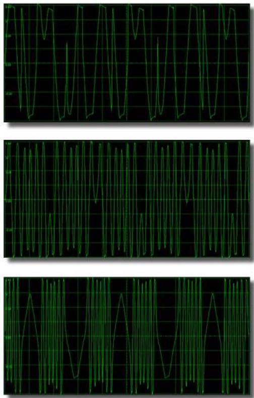
natural_image
Three identical green waveform graphs showing synchronized oscillations on black background, no text or symbols present.The wave folder output for a triangle wave input. From top to bottom the FOLD level is increasing.
PRESET MODE
The SHAPESHIFTER module contains a 100-slot memory for storing parameter settings (called presets). All 100 of these preset slots are stored in non-volatile memory (i.e. they persist after turning the power off).
The user interacts with the preset memories while the module is in PRESET MODE. This mode is entered by pushing on the rotary encoder. The red LED above the rotary encoder will light up indicating that the module is now in PRESET MODE. Pushing the encoder a second time will leave PRESET MODE. Once in preset mode the buttons to the left of the rotary encoder change their function to allow the user to interact with the preset memories. There are four primary operations that can be done: SAVE, STEP, MORPH, and LOAD.
When PRESET MODE is first entered, the LCD display shows the currently selected preset and the display will read "Prset NN" (where NN is a number from 0 to 99). The selected preset can be changed by turning the rotary encoder. The 8-character name of the preset will be displayed on the second line of the display.
SAVE: While in preset mode the current parameter settings can be stored to the currently selected preset memory slot. To do this, first get into the state where the LCD display is showing the currently selected preset number (i.e. "Prset NN"). If the module is IN STEP or MORPH mode this state can be reached just by pressing either the WAVE BANK/SAVE or the CHORD TYPE/MULTI/LOAD buttons. Once the preset number is being displayed, use the rotary encoder to change the preset number to the slot in which you want to save. Then press the WAVE BANK/SAVE button (top button to the left of the encoder). The LCD display will change to show "Save? NO". If you do not actually want to save to this preset (because, for example, you pressed the button by accident or you changed your mind) just press the WAVE BANK/SAVE button again and nothing will happen. If you really do want to save to the preset, then turn the rotary encoder. The LCD display will now show "Save?YES". Press the WAVE BANK/SAVE button to save to the preset memory.
LOAD: When the LCD display is showing the preset number (i.e. "Prset NN") pressing the CHORD TYPE/MULTI/LOAD button (bottom button to the left of the encoder) will cause the contents of the currently selected preset to be read and the module's parameters updated with these stored values. Immediately after a preset is loaded, the panel controls will be set to soft pickup. This means that the settings will not necessarily correspond to the front panel's knob settings. Turning the knobs on the panels a little bit will break this alignment with the preset settings and the value will jump to that specified by the knob.
The number of the last preset to be loaded or saved is remembered, and is loaded upon powerup.
MORPH: The SHAPESHIFTER module allows you to morph between the current panel parameter settings and the settings stored in the currently selected preset. To activate this ability, press the MOD A/MORPH button (second from bottom button to the left of the rotary encoder). The LCD display will now show "Morph NN" (where NN is the currently selected preset number). The currently selected preset number can be changed by turning the rotary encoder. The parameter values actually used by the module in this situation will be a blending of the current panel settings and the parameters stored in the currently selected preset. The relative blending is controlled by the MOD B control (and MOD B input). When the MOD B control is fully counter-clock-wise the actual parameters will be the same as the panel settings, whereas if the MOD B control is fully clock-wise then the actual parameters will be those from the currently selected preset. When the MOD B control is somewhere in between, the actual parameters will be a blending of the two.
There are two exceptions to this blending: the INT. SYNC and PERC. MODE settings are always set to the panel configuration. The preset values for this buttons are ignored. Note that the currently selected preset can be changed on the fly using the rotary encoder, allowing the sounds to be rapidly changed during a performance. With the MOD B knob turned all the way clock-wise (so that the blending is completely to the preset values) this allows a quick way to audition the presets before loading them.
PRESET MODE (continued...)
STEP: The SHAPESHIFTER module also has the capability of stepping through the presets in response to triggers sent to the SYNC input or to the MODA Input if the MODA destination is set to "PrstStep". To activate this ability press the STEP button (second button from the top to the left of the rotary encoder). The stepping is done on presets in a user-definable range of preset numbers (the Begin and End presets). The STEP mode has seven different settings, accessed by turning the rotary encoder. These are described below:
Fwd : NN when this is selected, press the STEP button to turn on the stepping action. Each trigger received by the SYNC input will step the preset to the next highest number. The LCD display will change to show "Fwd *NN". The * indicates that stepping is live. To stop the stepping press the STEP button again.
Rev : NN this is the same as the Fwd setting except that each trigger will step to the next lower preset.
Fw/Rv: NN in this mode the stepping will first increase the preset number until the end preset number is reached, and then step downwards until the beginning preset number is reached, and the cycle repeats.
RandP : NN in this mode a random preset number in the range is selected on each trigger.
RandS : NN in this mode the module parameters are randomized on each trigger. Presets are not affected.
MOD B: NN in this mode the preset number selected on each trigger is set by the position of the MOD B knob (and by the MOD B input). This allows an external input to select or sequence the presets on each trigger.
Begin: NN when this is selected, press the STEP button. The LCD display will change to show "Begin? NN". In this state you can turn the rotary encoder to select the starting preset number for the stepping sequence. Once you have chosen the desired starting preset number, press the STEP button again and use the rotary encoder to select one of the other settings.
End : NN In a manner similar to the Begin setting, this allows you to select the ending preset number for the stepping sequence.
Div: N in a manner similar to the Begin setting, this mode sets the number of SYNC pulses per step. It is used when you want to repeat a preset for a number of sync pulses before stepping to the next one. N can range from 1 to 8. When set to 1, the preset will step on every sync pulse.
PPRESET NAMING : While in preset mode, the 8-character name of the currently selected preset is shown on the second line of the display. This name can be edited, by holding down the COMBO MODE button (top right button) and pressing the STEP button. The first line of the display will read "EditName" and the blinking cursor will move to the second line of the display to indicate which character is being edited. Change the character by rotating the rotary encoder. Pressing the COMBO MODE button will step the cursor to the next character. While in the name editing mode, holding down the COMBO MODE button and pressing the SAVE button will randomize the preset name (only).
In any Preset Mode situation, holding down the COMBO MODE button and pressing the MORPH button will randomize all of the module parameters (including the name). Likewise, holding down the COMBO MODE button and pressing the LOAD button will set the module parameters to the default all-zero settings, and the preset name will be set to "BASICO". Note that any changes to the preset name and module parameters will only be stored when you do a SAVE operation.
Technical Details
The digital portion of the SHAPESHIFTER module is implemented in an Altera Cyclone IV Field Programmable Gate Array (FPGA). The use of Gate Array technology rather than a general purpose programmable microcontroller or DSP chip allows highly efficient implementation of fast parallel operations.
The primary logic blocks are clocked at a rate of 25MHz. The phase accumulators of the 9 oscillators are updated at this rate, as well as the nonlinear combo operations. This results in very low aliasing noise for the nonlinear combo operations and for the frequency and phase modulations. The phase accumulators are 55-bits in width, allowing for very low frequency operation and high quality frequency and phase modulation.
The contents of the relatively slow wavetable EPROM are copied to fast SDRAM memory when the module is first powered up. The SDRAM is then clocked at a rate of 100MHz. This results in a fast read rate of the wavetables - when CHORD mode is off the wavetables for each oscillator are read at a sampling rate of 3MHz. When chord mode is on the wavetable read rates drop to 700KHz per oscillator, which is still high enough to minimize aliasing noise. Linear interpolation is performed between successive samples, providing smooth waveforms even at low frequencies. Each wavetable sample is digitally represented with 16 bits, and each waveform in the wavetable consists of 512 samples. There are 1024 different waveforms stored in the wavetable.
Most of the signal processing in the module is done at a 25MHz sampling rate. The signals are then filtered and down-sampled to 98KHz (25Mhz/256) before being output by the Digital to Analog Converters. Some of the signal processing (the delay line and the vocoder filter banks) is done at the lower output sampling rate. The PULSE output is sent at the primary 25MHz sample rate, although it is passed through an analog buffer which rolls off the high frequencies.
The input signals MOD A and FM1 are converted to digital form by 24-bit Analog-to-Digital Converters running at a sampling rate of 98KHz. The input signals PITCH1, PITCH2, INT. FM, RATIO, SHAPE1, SHAPE2 and MOD B are converted to digital form with 12-bit Analog-to-Digital Converters running at 25KHz sampling rates. The SYNC input signal is sampled at 25MHz and converted directly to a 1-bit digital representation. The FOLD and FOLD_CV inputs are not converted to digital form; instead they are fed directly into the analog wave folder circuitry.
Rear View of the Module
natural_image
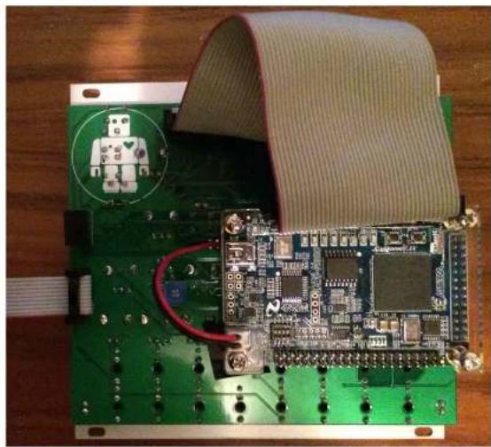
Green printed circuit board with a robot icon and ribbon, no visible text or symbolsIf your module is acting erratically, or not working at all, make sure that all cables on the back are securely connected. The top 40-pin cable connects the front panel board to the FPGA board. The left-hand 10-pin cable connects the module to the Doeffer format power supply. The -12V pin of the cable (usually the one marked in red) must be oriented towards the bottom of the module. The two-wire (red-black in the photo above) provides the +5V power to the FPGA board. If it is correctly connected you will see a blue LED light up on the FPGA board.
The silver connector directly above the +5V power connector on the FPGA board is a mini-B USB connector, which is used to update the firmware on the FPGA (see appendix C for details).
Loading the Factory Presets
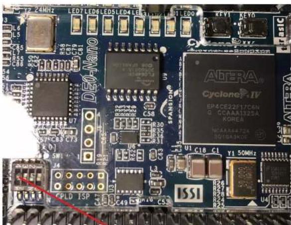
If your module was purchased with a firmware version prior to version 2.01 it will not have the factory presets installed. If you wish to install these, do the following:
Before powering on the module, put the left-most of the tiny switches on the rear circuit board (in the bottom left part of the board) to the up position. Then power up. This will initialize the preset memory to the factory settings. Then go into preset mode and press SAVE and move the encoder to get the "Y?" and press SAVE again. This will store the factory presets into the non-volatile memory. Then power down and put the switch back to the down position. The next time you power up, the factory presets will be ready for use. You can still overwrite these if you want, but they are instructive and perhaps you might even find them useful.
Version
This manual is for version 2.03 of the module's firmware.
To determine the firmware version, enter the PRESET MODE (by pushing on the rotary encoder), then press the LOAD button while holding down the DETUNE button. When this is accomplished, the LCD screen will alternate between displaying "shapshift/ver 2.03", and "CYLONIX/intlijel".
Please refer to Appendix C of this manual for Instructions on updating the module's firmware.
Changelog
Version 2.03
- Fixed: Eliminated the display glitching observed on some modules.
Version 2.02
- Added: When turning the ENCODER rapidly while viewing the WAVE BANK or CHORD TYPE the scrolling will stop at the extremes of the range. Turning the ENCODER slowly will allow the scrolling to wrap around.
Version 2.01
- Added: the CHORD TYPE parameter can now be controlled by the MODB signal.
- Added: the wave bank selection for oscillators 1 and 2 can now be controlled by the MODB signal,
- Added: the two oscillators now have independently selectable SYNC MODES, and both now have 1-shot and Hold modes.
- Added: pressing the INT. SYNC button twice causes the Internal sync event generator to drop in frequency by one octave (the INT. SYNC LED flashes when this mode is selected).
- Added: when the QUANT. button is pressed twice the PITCH2 input becomes a CLOCK input for oscillator 2, where the period of the oscillator 2 cycle is equal to the input clock period. The QUANT. led flashes in this mode. In this mode the RATIO Input sets the clock division/multiplication factor.
- Added: 8 more pulse modes, including PWM, Square and random.
- Added: added another mode to the PRESET STEP menu, where the preset is randomized on each step.
- Added: pressing COMBO MODE and MORPH while in PRESET MODE randomizes the settings.
- Added: pressing DETUNE and LOAD while in PRESET MODE displays the firmware version.
- Added: the oscillator 2 output can be directed to modulate the SHAPE1 or TILT parameters.
- Added: the MODA signal can now be used to serve as the SYNC source for oscillator 1 or to step presets.
- Changed: the DECAY parameter range has been changed to give a smoother change with more values at longer decay times.
- Changed: the PERC. MODE LED now flashes when the Gate behaviour is selected (by pressing the PERC. MODE button twice).
- Changed: the initial part of the INT. FM control curve has been changed to give more resolution at the low end.
- Changed: the number of presets has been increased to 100 and all presets are now stored in non-volatile memory. The presets now have user-definable 8-character labels, which can be randomized.
- Changed: the number of the last preset to be loaded or saved is remembered, and is loaded upon powerup (previously preset# 1 was loaded on powerup).
- Changed: the range of the TILT parameter has been lowered by a factor of 4. This gives more resolution in
the interesting range of the tilt effect.
- Changed: the bank numbers and chord type no longer wrap around, making it easier to reach the ends.
- Changed: knobs are set to soft-pickup after a preset is loaded, even when leaving preset mode. Soft-pickup action is changed so that the knob takes over from the preset value when it is moved a little bit.
- Changed: the labels for the MODA destinations "Shape1" and "Shape2" have been changed to "Shaper1" and "Shaper2" to better reflect the actual behaviour in these modes.
- Fixed: Added a short (4msec) delay to the MODB Preset Stepping after the sync pulse is received. This is needed because many sequencers send the gate signal before the voltage has settled to its new value.
Version 1.04
- Added: pressing the PERC. MODE button twice activates GATE mode, where the SYNC Input acts as a gate for Out1. When the SYNC input goes high the Out1 envelope immediately goes high. When the SYNC input goes low the Out1 envelope decays at a rate set by the DECAY parameter.
• Fixed: The logic of the Pulse mode was inverted.
Version 1.03
- Added: 4 new MODA destinations, swapping Osc2 by Osc1 in the Phase, Combo, and Shape destinations, and swapping the Carrier and Modulator in the vocoder.
- Changed: The modulation range for the Phase modulation (by MODA) and the Tilt function (internal self-phase modulation of Osc1) has been increased 4-fold.
- Fixed: In version 1.01 and version 1.02 the Shape1 and Shape2 parameters were coarsely quantized when Morphing between panel and preset settings in Preset Morph mode. The Shape parameters now smoothly morph between settings.
- Fixed: The pitch of oscillator 2 increased when changing the Multi mode with QUANT turned on. The pitch now remains constant over all multi modes.
Version 1.02
- Added: Users can now choose between just intonation or equal temperament tunings in chord mode.
- Added: Holdsync mode has been changed to do holdsync for osc1 and oneshot for osc2.
- Added: A confirmation message is now displayed when a preset is loaded.
Version 1.01
- Added: The version number of the firmware is now displayed when entering the SplashScreen display.
- Fixed: In version 1.00 there were small discontinuities in the waveforms when the Shape1 and Shape2 parameters were rapidly modulated. These have been eliminated.
Technical Specifications
Inputs:
PITCH1, PITCH2: -5 to +7V (1V/Oct scaling)
All other inputs: -5V to +5V
Outputs:
OUT1, OUT2: 12 Vp-p FOLD: 10Vp-p (occasional peaks to 16Vp-p) PULSE: 0 to +5V
Max Current Draw:
+195 mA in normal operation (from +12V supply, with occasional peaks to +220 mA) -50 mA (from -12V supply)
Module Dimensions:
Width: 26HP Depth: 40mm
Warranty
IntelliJel Designs Inc. warrants this hardware product against defects in materials and workmanship when used normally in accordance with IntelliJel's published guidelines for a period of TWO (2) YEARS from the date of original retail purchase by the end-user purchaser ("Warranty Period").
This warranty does not cover any damage or malfunction caused by Incorrect use – such as, but not limited to, power cables connected backwards/incorrectly, connection of excessive voltage levels, or exposure to extreme temperature and/or moisture levels.
The warranty covers replacement or repair, as decided by Intellijel Designs Inc.. Please contact our customer service (support@intellijel.com) for a return authorization before sending the module. The freight cost of sending a module back for servicing is the responsibility of the customer. Intellijel implies and accepts no responsibility for harm to person or apparatus caused through operation of this product.
APPENDIX A - BANK BY BANK GRAPHICAL WAVETABLE DISPLAY
| Basic1 | Basic2 | BaseRec | BiPuls | BiCr1 | BiCr2 | BiCr3 | BiCr4 | Buzzer | Cello1 | Cello2 | Chip1 | Chip2 | Chip3 | Chip4 | Chip5 |
| Chip0 | |||||||
| Chip1 | |||||||
| Chip2 | |||||||
| Chip3 | |||||||
| Chip4 | |||||||
| Chip5 | |||||||
| Chip6 | |||||||
| Chip7 | |||||||
| Chip8 | |||||||
| Chip9 | |||||||
| Chip10 | |||||||
| Chip11 | |||||||
| Chip12 | |||||||
| Chip13 | |||||||
| Chip14 | |||||||
| Chip15 |
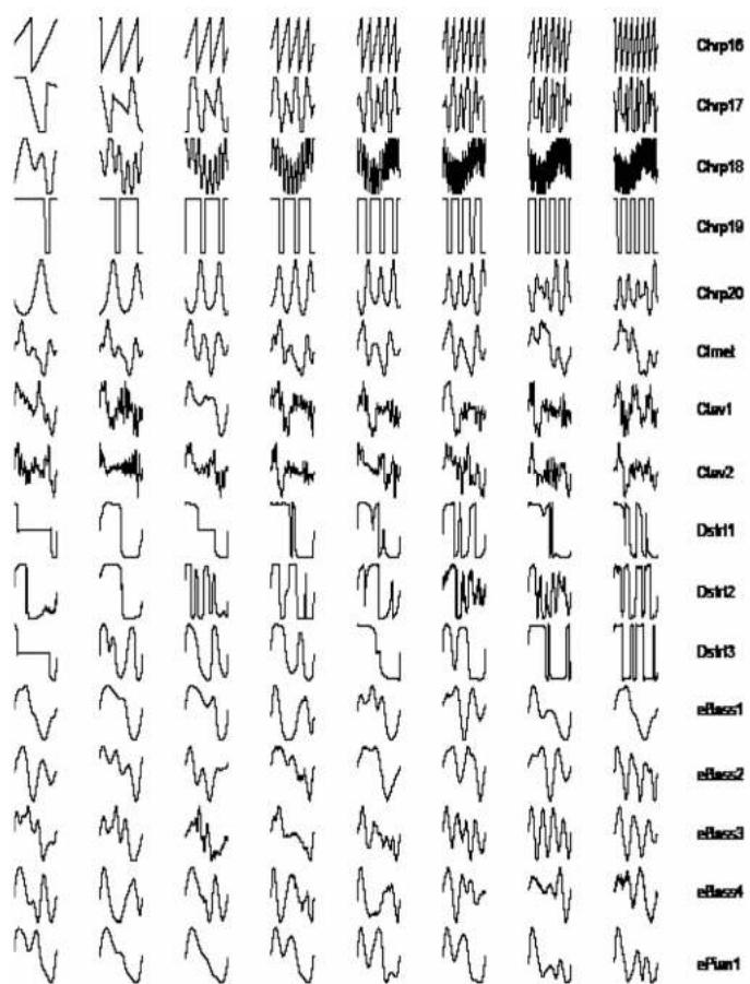
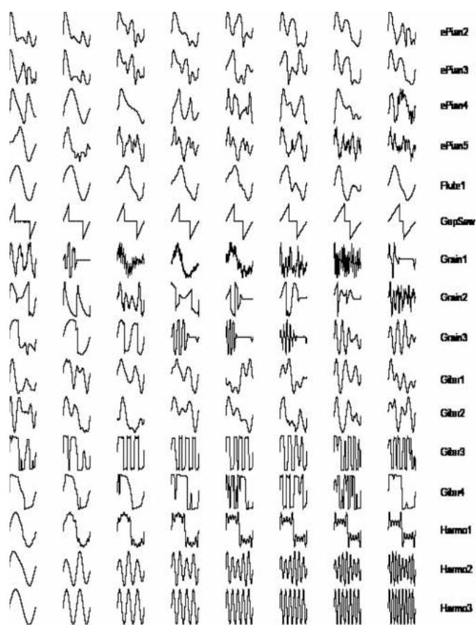
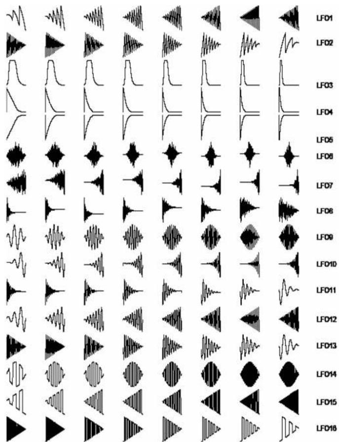
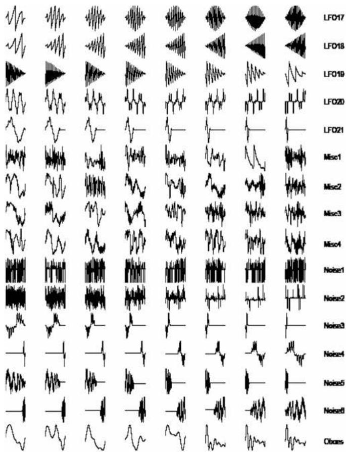
APPENDIX B - UPGRADING THE MODULE'S FIRMWARE
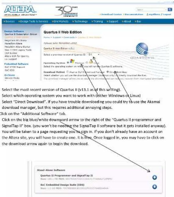
To update the Shapeshifter module's firmware, it is simplest (although not simple) to use the Altera Quartus II Standalone programmer software. This software is available for Windows or Linux. The Windows program can be run on a Mac using Parallels. The following is the instructions for Windows 7.
- Go to the Altera.com web site to download the Standalone programmer software. http://dl altera.com/?edition=web
-
Find the program that was downloaded (it will be named something like QuartusProgrammerSetup-13.1.0.162.exe) and run it.
-
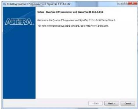
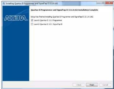
The Quartus II Programmer and SignalTap II installation window will appear.
- Go through all of the installation steps, specifying the install directory and so forth.
- Next, you may need to manually install the driver for the USB-Blaster device. This is the driver for the USB connection to the Shapeshifter module.
- Connect a USB cable between your computer and the small board (Terasic DIO-Nano board) on the rear of the Shapeshifter module. Note that the board on the Shapeshifter takes in a MINI-B plug. You will need a USB cable with this type of connector. Once the USB connection has been made, the blue LED on the back of the Shapeshifter module should light up. Some of the LEDs on the front panel may light up as well.
- If Windows indicates that it can't find the driver for the USB device, then do the following (on Windows 7):
a. Press the Start button and go to Devices and Printers
b. Right click USB-Blaster and select Properties
c. Select the Hardware-tab and again, select Properties
d. Select Change Settings go to the Driver-tab and select Update Driver
e. In the pop-up window, select Browse my computer for driver software
f. Under Search for driver software in this location copy/paste
C:\altera\13.1\qprogrammer\drivers\usb-biaster (Note that C:\altera is the default install location and directory number will change if you install a different version.)
g. Click Next
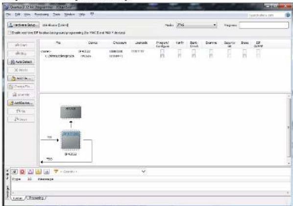
- Once the program and the drivers are all installed, run the standalone programmer. The Quartus II 32-bit Programmer window will appear.
![Quartus 12.04 Programmer - [FileList] File Edit View Procving Zone Window Help My Documents: No Software Mode: Auto Engine: Model and key tool to select background programming (For NC-3 and new / device) Name Description COMPUTS LIMITED Program/Configure API COMPUTS COMPUTS COMPUTS COMPUTS COMPUTS COMPUTS COMPUTS COMPUTS COMPUTS COMPUTS COMPUTS COMPUTS COMPUTS COMPUTS COMPUTS COMPUTS COMPUTS COMPUTS COMPUTS COMPUTS COMPUTS COMPUTS COMPUTS COMPUTS COMPUTS COMPUT S OK \\n Name DRAW CONCUI NUCRIL PKPCP/COGRC EHTI SNCR-CNC CNVRC SNVRV SNVRV SNVRV SNVRV SNVRV SNVRV SNVRV SNVRV SNVRV SNVRV SNVRV SNVRV SNVRV SNVRV SNVRV SNVRV SNVRV SNVRV SNVRV SNVRV SNVRV SNVRV SNVRV SNVRV SNVRV SNVR V OK Nu#&J Spectra /U /Priemware / / / / / / / / / / / / / / / / / / / / / / / / / / / / / / / / / / / / / / / / / / / / / / / / / / /Y /Priemware /U /Priemware /](/content/2026/05/896895/images/41114dc765f44a565adcef962ea52d9ca514ab5a0d79837bb3f4e13f27e2ac79.jpg)
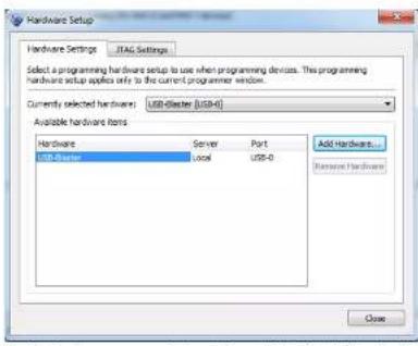
- Make sure that the "Mode" tab in the top line of the Programmer window is set to "JTAG". Click on "Hardware Setup". The "Hardware Setup" window will appear. Under "Available hardware items" a line listing "USB-Blaster" should be present. Double-click on this line. The item "Currently selected hardware:" should change to say "USB-Blaster. Close this window,
- Back in the Programmer window, click on "Add File". In the directory dialog window that appears, select the Shapeshifter configuration update file (the .jic file, not the .bin file) that you wish to install. This file can be obtained from the Intellijel website. The programmer window will change and look something like the following:
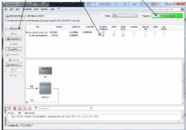
- Click on the check-box in the second row under the Program/Configure column. The "Start" button should no longer be grayed-out.
- Click on the "Start" button to begin the download of the configuration file to the Shapeshifter board. The download process will take about 20 seconds. The Progress bar will show the progress of the downloading and when complete will read "100% (Successful)".
- The Shapeshifter board will now be updated and ready to go!
APPENDIX D - CHANGING THE WAVETABLE SAMPLES
How to load your own samples into the Wavetable EPROM.
- You can load your own waves into the Wavetable EPROM using the Terasic Control Panel program. This program is also useful for testing out parts of the Shapeshifter board, such as the ADC channels.
- The wave data for the Shapeshifter module is stored in the same 2MByte EEPROM as the module's FPGA configuration. The EEPROM is not directly accessible, but can be programmed using the Terasic Control Panel program. It requires that the entire EEPROM be erased and reloaded whenever changes are made. So, changing the wavetable data requires editing the firmware data, erasing the Shapeshifter EEPROM, and loading the edited data back into the EEPROM.
- Editing the firmware file can be done with any capable binary editing software. A suitable program is the WinHEX program from X-Ways (http://www.x-ways.net/winhex/index-m.html).
- Download the current version of the Shapeshifter firmware from the Intellijel web site and load this into the binary editor program (the screenshot below is from the WinHEX program):
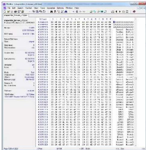
- The wavebank names are also stored in the firmware file. These are stored beginning at address 0F000 (hex). See the screenshot above for the names in the factory firmware. Each name is stored in 8 consecutive bytes, and encoded in ASCII. The name for bank 1 starts at 0F0000, that for bank 2 at 0F0008, and so on through all 128 banks. You can use the binary editor to overwrite the memory with the names you want for your waves. For best results, limit the names to 6 characters, setting the first 2 characters to spaces.
- The wavetable waves are stored in the firmware memory starting at address 100000 (hex). Each wave consists of 512 two-byte (16-bit) signed (2's-complement) samples. The first wave starts at address 100000, the second at address 100400, the third at address 100800 and so on. There are 1024 waves in the wavetable memory. You can change some or all of them. Note that each 2-byte sample is stored in little-endian (Intel) format, where the first byte is the least significant byte and the second is the most-significant.
- It is most convenient to produce banks of 8 waves at a time in a sample editing program (e.g. Adobe Audition). Such a sound file would then have 4096 16-bit samples, split into 8 different segments of 512 bytes, each corresponding to one of the waves in the bank. Save the wave bank in the sample editing program as a 16-bit Intel PCM RAW format file. For example, in using Adobe Audition you would set the file save options as follows:
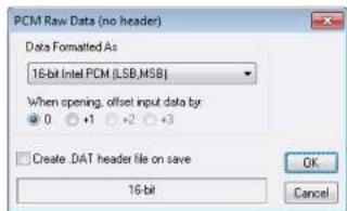
- Once you have a new wave load it into the binary editor and overwrite the desired wave bank in the Shapeshifter firmware file using the cut and paste operations of the binary editor.
- Once all of the new waves have been written into the firmware file, save the file, giving it a different name than the original firmware file (e.g. something like shapeshifter_firmware_modified.bin).
-
If you haven't already, download and install the Altera Quartus Standalone Programmer. The Terasic Control Panel makes use of some of the components of the Altera program.
-
Go to the Terasic Company's download site (http://www.terasic.com/downloads/cd-rom/de0-nano/) and download the zip file or rar file for the ControlPanel software.
![Index of /downloads/ x8.xx/ x9.xx/ Directories Name Last modified 2017-03-25 11:43 Description Files Name size Last modified 200_Kam_CormiFwd_v1.1.2.psc 5.04 2015-12-15 10:56 200_Kam_CormiFwd_v1.1.2.jp 4.24 2015-12-15 10:56 200_Kam_v1.0_20009.2s 27.04 2015-12-15 10:57 200_Kam_v1.0.4_10007.jp 41.24 2016-12-15 10:57 Simple Filled VarLLS [20070310]](/content/2026/05/896895/images/cd0d9eb1f451a52db23ddf07e81f9220c1b7987d63a2e950f0ef3b30b9bb2150.jpg)
- Unzip the file into some directory.
- Connect a USB cable between your computer and the small board (Terasic DEO-Nano board) on the rear of the Shapeshifter module. Note that the board on the Shapeshifter takes in a MINI-B plug. You will need a USB cable with this type of connector. Once the USB connection has been made, the blue LED on the back of the Shapeshifter module should light up. Some of the LEDs on the front panel may light up as well.
- Run the DEO_Nano_ControlPanel.exe program. The program will try to connect to the DEO-Nano board on the Shapeshifter module and say "Connected" if successful.

- Click on the "Memory" tab on the left hand side. In the "Memory Type" menu on the right hand side, choose "EPCS (100000h WORDS, 2MB)". This will select the configuration EPROM on the Shapeshifter board.
- Because of the way in which the EPROM is written, you first have to erase the entire EPROM. Once you do this, your Shapeshifter board will no longer be functional, so take a deep breath, and then press the "Chip Erase (30 sec.)" button. The erasing process actually takes about 2 minutes, not 30 seconds.
- In the "Sequential Write" section click on the box "File Length" and then click on "Write a File to Memory". Select the shapeshifter_firmware_modified.bin file.
- A progress window will appear. The writing process will take about 16 minutes (!). Do not disconnect the board from the computer during this process; otherwise you will have to restart the writing process. Once the writing has been completed your Shapeshifter board will be updated and ready to go!
![Terasic DE0-Nano Control Panel V1.0 LED Switches Memory Accelerometer ADC Connected DISCONNECT AERIA. UNIVERSITY teraslc CycloneC (L) [55] Memory Type EPCS (100000h WORDS, 2 MB) Random Access Address: 00000000 wDATA: 0000 rDATA: 0000 Chip Erase (30 sec.) Write Read Sequential Write Address: 00000000 Length: 100000 File Length Write a File to Memory Sequential Read Address: 00000 Length: 100000 Entire Memory Load Memory Content to a File Note. Please erase EPCS first before writing data. Write a File to EPCS Aborted.](/content/2026/05/896895/images/d44df465afaaf54a27e774da228ca9125c17c622d0ceda50a176afa4a126ba88.jpg)
- Front Panel Elements (numbers refer to the diagram on the first page)
- Front Panel Elements (continued...)
- Oscillator Waveforms
- Oscillator 2 Pitch Setting
- Nonlinear Waveform Combination Modes
- Oscillator SYNC Modes
- PULSE Source Modes
- MOD A Destinations
- CHORD MODE
- CHORD MODE (continued...)
- MULTI SETTINGS
- TILT FUNCTION
- DRIVE FUNCTION
- DELAY FUNCTION
- PERCUSSION MODE
- WAVE FOLDER
- PRESET MODE
- The number of the last preset to be loaded or saved is remembered, and is loaded upon powerup.
- PRESET MODE (continued...)
- Technical Details
- Rear View of the Module
- Loading the Factory Presets
- Version
- Changelog
- Version 2.03
- Version 2.02
- Version 2.01
- Version 1.04
- Version 1.03
- Version 1.02
- Version 1.01
- Technical Specifications
- Inputs:
- Outputs:
- Max Current Draw:
- Module Dimensions:
- Warranty
- APPENDIX B - UPGRADING THE MODULE'S FIRMWARE
- Devices | Design Tools & Services | End Markets | Technology | Training | Support | About | Buy
- APPENDIX D - CHANGING THE WAVETABLE SAMPLES
Brand : Intellijel
Model : Shapeshifter
Category : Keyboard