9172 - Temperature regulator FLUKE - Free user manual and instructions
Find the device manual for free 9172 FLUKE in PDF.


| Product Type | Temperature Regulator (Metrology Well) |
| Model | Fluke 9172 |
| Temperature Range | 35°C to 425°C (95°F to 797°F) |
| Display Accuracy | ±0.1°C (35°C to 100°C); ±0.15°C (100°C to 225°C); ±0.2°C (225°C to 425°C) |
| Stability | ±0.005°C (35°C to 100°C); ±0.008°C (100°C to 225°C); ±0.01°C (225°C to 425°C) |
| Axial Uniformity (40 mm) | ±0.05°C (35°C to 100°C); ±0.09°C (100°C to 225°C); ±0.17°C (225°C to 425°C) |
| Well Depth | 203 mm (8 in) |
| Resolution | 0.001°C / 0.001°F |
| Display | LCD, °C or °F user-selectable |
| Heating Time | 27 min from 35°C to 425°C |
| Cooling Time | 220 min from 425°C to 35°C; 100 min from 425°C to 100°C |
| Dimensions (H x W x D) | 366 x 203 x 323 mm (14.4 x 8 x 12.7 in) |
| Weight | 12.2 kg (27 lb) |
| Power Supply | 115 V (±10%), 50/60 Hz, 1025 W or 230 V (±10%), 50/60 Hz, 1025 W |
| Fuse Ratings (System) | 115 V: 10 A 250 V; 230 V: 5 A 250 V |
| Computer Interface | RS-232, includes 9930 Interface-it control software |
| Safety Features | Over-temperature cutout (software adjustable), block temperature indicator (LED) for temperatures above 50°C, hot surface warning |
| Reference Probe Input (-R models) | 5-pin DIN connector for 4-wire PRT (RTD/SPRT); supports ITS-90 and Callendar-Van Dusen characterizations |
| Included Accessories | Power cord, RS-232 cable, Getting Started Guide, User's Guide, Report of Calibration, DIN connector (-R only), tongs (insert removal tool), well insulator, 9930 Interface-it software, one insert (model-specific) |
| Optional Accessories | Interchangeable probe sleeves (models 9172-INSA to INSZ), carrying cases, custom inserts |
| Warranty | One year for instrument, 90 days for parts, repairs, and software |
Frequently Asked Questions - 9172 FLUKE
User questions about 9172 FLUKE
0 question about this device. Answer the ones you know or ask your own.
Ask a new question about this device
Download the instructions for your Temperature regulator in PDF format for free! Find your manual 9172 - FLUKE and take your electronic device back in hand. On this page are published all the documents necessary for the use of your device. 9172 by FLUKE.
USER MANUAL 9172 FLUKE
Limited Warranty & Limitation of Liability
Each Hart Metrology Well from Fluke Corporation (“Fluke”) is warranted to be free from defects in material and workmanship under normal use and service. The warranty period is one year. The warranty period begins on the date of the shipment. Parts, product repairs, and services are warranted for 90 days. The warranty extends only to the original buyer or end-user customer of a Fluke authorized reseller, and does not apply to fuses, disposable batteries or to any other product which, in Fluke’s opinion, has been misused, altered, neglected, or damaged by accident or abnormal conditions of operation or handling. Fluke warrants that software will operate substantially in accordance with its functional specifications for 90 days and that it has been properly recorded on non-defective media. Fluke does not warrant that software will be error free or operate without interruption. Fluke does not warrant calibrations on Hart Metrology Wells.
Fluke authorized resellers shall extend this warranty on new and unused products to end-user customers only but have no authority to extend a greater or different warranty on behalf of Fluke. Warranty support is available if product is purchased through a Fluke authorized sales outlet or Buyer has paid the applicable international price. Fluke reserves the right to invoice Buyer for importation costs of repairs/replacement parts when product purchased in one country is submitted for repair in another country.
Fluke's warranty obligation is limited, at Fluke's option, to refund of the purchase price, free of charge repair, or replacement of a defective product which is returned to a Fluke authorized service center within the warranty period.
To obtain warranty service, contact your nearest Fluke authorized service center or send the product, with a description of the difficulty, postage, and insurance prepaid (FOB Destination), to the nearest Fluke authorized service center. Fluke assumes no risk for damage in transit. Following warranty repair, the product will be returned to Buyer, transportation prepaid (FOB Destination). If Fluke determines that the failure was caused by misuse, alteration, accident or abnormal condition or operation or handling, Fluke will provide an estimate or repair costs and obtain authorization before commencing the work. Following repair, the product will be returned to the Buyer transportation prepaid and the Buyer will be billed for the repair and return transportation charges (FOB Shipping Point).
THIS WARRANTY IS BUYER'S SOLE AND EXCULSIVE REMEDY AND IS IN LIEU OF ALL OTHER WARRANTIES, EXPRESS OR IMPLIED, INCLUDING BUT NOT LIMITED TO ANY IMPLIED WARRANTY OF MERCHANTABILITY OR FITNESS FOR A PARTICULAR PURPOSE. FLUKE SHALL NOT BE LIABLE FOR ANY SPECIAL, INDIRECT, INCIDENTAL. OR CONSEQUENTIAL DAMAGES OR LOSSES, INCLUDING LOSS OF DATA, WHETHER ARISING FROM BREACH OF WARRANTY OR BASED ON CONTRACT, TORT, RELIANCE OR ANY OTHER THEORY.
Since some countries or states do not allow limitation of the term of an implied warranty, or exclusion or limitation of incidental or consequential damages, the limitations and exclusions of this warranty may not apply to every buyer. If any provision of this Warranty is held invalid or unenforceable by a court of competent jurisdiction, such holding will not affect the validity or enforceability of any other provision.
Fluke Corporation 799 E. Utah Valley Drive American Fork, UT 84003-9775 USA Phone: +1.801.763.1600 Telefax: +1.801.763.1010 Email: support@hartscientific.com
www.hartscientific.com
Subject to change without notice. Copyright © 2005 Printed in USA
Table of Contents
1 Before You Start ....1
1.1 Introduction ...... 1
1.2 Symbols Used .... 1
1.3 Safety Information ...... 2
1.3.1 Warnings 2
1.3.2 Cautions 4
1.4 CE Comments 5
1.4.1 EMC Directive ....5
1.4.2 Immunity Testing ....5
1.4.3 Emission Testing 6
1.4.4 Low Voltage Directive (Safety) 6
1.5 Authorized Service Centers 6
2 Specifications and Environmental Conditions .....9
2.1 Specifications 9
2.2 Environmental Conditions ...... 10
3 Quick start ....13
3.1 Unpacking 13
3.2 Setup 14
3.3 System Setup 15
3.4 Display 15
3.4.1 Measure 15
3.5 Setting the Temperature 16
3.5.1 Set-point Setup 16
3.6 Reference Probe (-R models only).... 16
3.6.1 Probe Connection .... 17
3.6.2 Measure Temperature 17
4 Parts and controls ....19
4.1 Back panel 19
4.2 Front panel 20
4.3 Front Panel Display 22
4.4 Front Panel Buttons 22
4.5 Accessories 24
5 Controller operation....27
5.1 Main Screen 27
5.2 Main Menu 29
5.2.1 Temp Menu ....30
5.2.1.1 Set 30
5.2.1.2 Preset 31
5.2.1.3 Setup 32
5.2.1.4 Cutout 33
5.2.2 Ref Menu (-R instruments only) 34
5.2.2.1 Select....35
5.2.2.2 Setup 36
5.2.2.3 Test 38
5.2.2.4 Focus (-R instruments only).... 39
5.2.3 Prog Menu 40
5.2.3.1 Select....40
5.2.3.2 Setup 41
5.2.3.3 Run 42
5.2.3.4 Switch Menu 43
5.2.4 System Menu 49
5.2.4.1 Setup menu 50
5.2.4.2 Cal Menu 54
5.2.4.3 Pass....60
5.2.4.4 Info (view only) 61
5.3 Menu Structure 62
6 Digital communication interface....67
6.1 Wiring 67
6.1.1 Setup 68
6.1.2 Serial Operation 68
6.2 Command Syntax 68
6.3 Commands by Function or Group 69
6.4 Serial Commands - Alphabetic Listing 72
6.5 Non-SCPI Process Commands 88
6.6 Non-SCPI Command by Function or Group 89
7 Calibration of your Metrology Well 93
7.1 General 93
7.2 Terminology....93
7.3 Fundamentals 93
7.4 Procedure 97
7.4.1 Manual readout tests .....97
7.4.2 Manual heat source calibration 99
7.4.3 Hysteresis....104
8 Maintenance ....105
8.1 Regular metrology well performance analysis 105
9 Troubleshooting ....107
9.1 Troubleshooting 107
Figures
Figure 1 Probe connector wiring.... 17
Figure 2 Metrology Well back panel view 19
Figure 3 Metrology Well front panel view 21
Figure 4 Metrology Well insert options. Probe sizes indicated in inches for A, B, and C, and millimeters for sleeves D, E, and F except for 0.25 inch reference holes in E and F. 25
Figure 5 Main screen display.... 27
Figure 6 MAIN MENU 29
Figure 7 TEMPERATURE MENU ....30
Figure 8 CONTROL SETPOINT menu....30
Figure 9 SELECT POINT menu 31
Figure 10 PRESETS SETUP menu....32
Figure 11 CUTOUT SETTINGS menu 33
Figure 12 REFERENCE MENU 34
Figure 13 PROBE SELECT menu 35
Figure 14 SETUP PROBE menu 36
Figure 15 PROBE TEST menu 38
Figure 16 FOCUS SELECT menu 39
Figure 17 PROGRAM MENU 40
Figure 18 PROGRAM SELECT menu 40
Figure 19 PROGRAM SETUP menu 41
Figure 20 PROGRAM RUN menu 42
Figure 21 SWITCH MENU 43
Figure 22 SWITCH TEST SELECT menu 44
Figure 23 SWITCH TEST SETUP menu 44
Figure 24 SWITCH TEST RUN menu 46
Figure 25 SWITCH TEST RESULTS menu 47
Figure 26 SYSTEM MENU 49
Figure 27 SETUP MENU 50
Figure 28 DISPLAY SETTINGS menu....50
Figure 29 MEASUREMENT SETTINGS menu .... 51
Figure 30 OPERATION SETTINGS menu 52
Figure 31 COMMUNICATION SETUP menu 53
Figure 32 CALIBRATION MENU 54
Figure 33 SETUP CONTROLLER menu 55
Figure 34 SENSOR SETTINGS menu .... 56
Figure 35 CUTOUT CALIBRATION menu .... 58
Figure 36 REFERENCE CALIBRATION menu 59
Figure 37 PASSWORD SETUP 60
Figure 38 SYSTEM INFO menu 61
Figure 39 RS-232 Wiring 67
Figure 40 Flow chart for readout calibration .... 95
Figure 41 Flow Chart for heat source calibration 96
Tables
Table 1 Symbols ...... 1
Table 2 Metrology Well Specifications ...... 9
Table 3 Built-in Readout Specifications ...... 10
Table 4 Matching Certificate Values to 917X ITS-90 Coefficients .... 37
Table 5 Setting Coefficients Rtpw, a8, b8, a4, and b4 37
Table 6 Commands by function or group ...... 69
Table 7 Test equipment specifications 94
Table 8 Standard resistor specifications .... 94
Table 9 One-year accuracy specifications .... 97
Table 10 Limits of standard deviation of measurement 97
Table 11 Required order for adjustment parameter.... 98
Table 12 Serial command, adjustment parameters ...... 98
Table 13 Axial gradient as found/as left specifications .... 100
Table 14 Heat source as found data/as left data specifications .... 100
Table 15 As left axial alignment specs ...... 102
Table 16 Heat source accuracy adjustment specifications .... 103
1 Before You Start
1.1 Introduction
Fluke's Hart Metrology Wells (9170, 9171, 9172, and 9173) are designed to be stable heat sources that can be used in a laboratory or field environment. With a calibrated display and an optional built-in reference thermometer input (designated with “-R”), Metrology Wells may also be used as a reference standard.
Metrology Wells feature interchangeable probe sleeves that fit various sized diameter probes.
The Metrology Wells' controller uses a PRT sensor and thermoelectric modules or heaters to achieve stable, uniform temperatures throughout the block.
The LCD display continuously shows many useful operating parameters including the block temperature, block stability, heating and cooling status, and current set-point. The temperature may be easily set with the control buttons to any desired temperature within the calibrator's specified range.
Metrology Wells are designed for laboratory performance that can be used anywhere. With proper use, the instrument will provide continued accurate calibration of temperature sensors and devices. Before use, the user should be familiar with the warnings, cautions, and operating procedures of the calibrator as described in the Getting Started Guide.
1.2 Symbols Used
Table 1 lists the symbols that may be used on the instrument or in this manual.
Table 1 Symbols
| Symbol Description Symbol Description | |||
 | AC (Alternating Current) PE Ground |  | |
 | AC-DC Hot Surface (Burn Hazard) |  | |
 | Battery |  | Read the User's Guide (Important Information) |
 | Complies with European Union directives |  | Off |
 | DC On | [1984] | |
| Double Insulated Canadian Standards | Ass | (1984) | |
 | Electric Shock C-TICK Australian EMC ma  | ||
 | Fuse |  | The European Waste Electrical and Electronic Equipment (WEEE) Directive (2002/96/EC) mark. |
| CAT II | OVERVOLTAGE (Installation) CATEGORY II, Pollution Degree 2 per IEC1010-1 refers to the level of Impulse Withstand Voltage protection provided. Equipment of OVERVOLTAGE CATEGORY II is energy-consuming equipment to be supplied from the fixed installation. Examples include household, office, and laboratory appliances. | ||
1.3 Safety Information
Use this instrument only as specified in this guide. Otherwise, the protection provided by the instrument may be impaired. Refer to the safety information in the Warnings and Cautions sections below.
The following definitions apply to the terms "Warning" and "Caution".
- “Warning” identifies conditions and actions that may pose hazards to the user.
- “Caution” identifies conditions and actions that may damage the instrument being used.
1.3.1 Warnings
To avoid personal injury, follow these guidelines.
GENERAL
DO NOT use this instrument in environments other than those listed in the User's Guide.
Inspect the instrument for damage before each use. DO NOT use the instrument if it appears damaged or operates abnormally.
Follow all safety guidelines listed in this guide.
Calibration equipment should only be used by trained personnel.
If this equipment is used in a manner not specified by the manufacturer, the protection provided by the equipment may be impaired.
Before initial use, or after transport, or after storage in humid or semi-humid environments, or anytime the Metrology Well has not been energized for more than 10 days, the instrument needs to be energized for a “dry-out” period of 2 hours before it can be assumed to meet all of the safety requirements of the IEC 1010-1. If the product is wet
or has been in a wet environment, take necessary measures to remove moisture prior to applying power such as storage in a low humidity temperature chamber operating at 50^ C for 4 hours or more.
DO NOT use this instrument for any application other than calibration work. The instrument was designed for temperature calibration. Any other use of the instrument may cause unknown hazards to the user.
Completely unattended operation is not recommended.
DO NOT place the instrument under a cabinet or other structure. Overhead clearance is required. Always leave enough clearance to allow for safe and easy insertion and removal of probes.
Use of this instrument at HIGH TEMPERATURES for extended periods of time requires caution.
Completely unattended high temperature operation is not recommended due to safety hazards that can arise.
If the instrument is used in a manner not in accordance with the equipment design, the operation of the Metrology Well may be impaired or safety hazards may arise.
This instrument is intended for indoor use only.
BURN HAZARD
Each Metrology Well is equipped with a Block Temperature Indicator (front panel LED HOT indicator – U.S. Patent 7,561,058) even when the instrument is unplugged. When the indicator is flashing, the instrument is not powered and the temperature of the block is above 50^ C. When the indicator is illuminated, always on, the instrument is powered and the block temperature is above 50^ C.
DO NOT turn the instrument upside down with the inserts in place; the inserts will fall out.
DO NOT operate instrument in any orientation other than vertical (block opening face up). Risk of fire or burn hazard may result due to excessive heat build up.
DO NOT operate on a flammable surface or near flammable materials.
DO NOT touch the well access surface of the instrument.
The block vent may be very hot due to the fan blowing across the heater block of the Metrology Well.
The calibration well temperature of the Metrology Well is the same as the actual display temperature, for example, if the instrument is set to 700^ C and the display reads 700^ C, the well is at 700^ C.
The air over the well can reach temperatures greater than 200^ C for high temperature ( 400^ C and higher) Metrology Wells.
Probes and inserts may be hot and should only be inserted and removed from the instrument when the instrument is operating at temperatures below 50^ C.
DO NOT turn off the instrument at temperatures higher than 100^ C. This could create a hazardous situation. Select a set-point less than 100^ C and allow the instrument to cool before turning it off.
The high temperatures present in Metrology Wells designed for operation at 300^ C and higher may result in fires and severe burns if safety precautions are not observed.
ELECTRICAL HAZARD
These guidelines must be followed to ensure that the safety mechanisms in this instrument will operate properly. This instrument must be plugged into a 115 VAC (230 VAC optional), AC only electric outlet. The power cord of the instrument is equipped with a three-pronged grounding plug for your protection against electrical shock hazards. It must be plugged directly into a properly grounded three-prong receptacle. The receptacle must be installed in accordance with local codes and ordinances. Consult a qualified electrician. DO NOT use an extension cord or adapter plug.
If supplied with user accessible fuses, always replace the fuse with one of the same rating, voltage, and type.
Always replace the power cord with an approved cord of the correct rating and type.
HIGH VOLTAGE is used in the operation of this equipment. SEVERE INJURY or DEATH may result if personnel fail to observe safety precautions. Before working inside the equipment, turn power off and disconnect power cord.
1.3.2 Cautions
To avoid possible damage to the instrument, follow these guidelines:
To properly calibrate the Metrology Well, the “Fan Limit” must be set to “Auto.”
DO NOT leave the sleeve(s) in the instrument for prolonged periods. Due to the high operating temperatures of the instrument, the sleeves should be removed after each use and buffed with a Scotch-Brite® pad or emery cloth (see the Maintenance section of the Users Guide).
Always operate this instrument at room temperature between 5^ C and 50^ C ( 41^ F and 122^ F). Allow sufficient air circulation by leaving at least 6 inches (15 cm) of clearance around the instrument. Overhead clearance is required. DO NOT place the instrument under any structure.
DO NOT interchange inserts between Metrology Well models. The inserts provided with the instrument as well as any additional inserts ordered are model specific.
Component lifetime can be shortened by continuous high temperature operation.
DO NOT apply any type of voltage to the switch terminals. Applying a voltage to the terminals may cause damage to the controller.
DO NOT use fluids to clean out the well. Fluids could leak into electronics and damage the instrument.
DO NOT introduce any foreign material into the probe hole of the insert. Fluids, etc. can leak into the instrument causing damage.
DO NOT change the values of the calibration constants from the factory set values. The correct setting of these parameters is important to the safety and proper operation of the calibrator.
DO NOT slam the probe sheath or sleeves into the well. This type of action can cause a shock to the sensor and affect the calibration.
The instrument and any thermometer probes used with it are sensitive instruments that can be easily damaged. Always handle these devices with care. DO NOT allow them to be dropped, struck, stressed, or overheated.
DO NOT operate this instrument in an excessively wet, oily, dusty, or dirty environment. Always keep the well and inserts clean and clear of foreign material.
The Metrology Well is a precision instrument. Although it has been designed for optimum durability and trouble free operation, it must be handled with care. Always carry the instrument in an upright position to prevent the probe sleeves from dropping out. The convenient handle allows for hand carrying the instrument.
If a mains supply power fluctuation occurs, immediately turn off the instrument. Power bumps from brown-outs could damage the instrument. Wait until the power has stabilized before re-energizing the instrument.
The probe and the block may expand at different rates. Allow for probe expansion inside the well as the block heats. Otherwise, the probe may become stuck in the well.
Most probes have handle temperature limits. Be sure the air temperature above the Metrology Well does not exceed the probe handle's temperature limit. If the probe handle limits are exceeded, the probe may be permanently damaged.
1.4 CE Comments
1.4.1 EMC Directive
Fluke's equipment has been tested to meet the European Electromagnetic Compatibility Directive (EMC Directive, 89/336/EEC). The Declaration of Conformity for your instrument lists the specific standards to which the instrument was tested.
The instrument was designed specifically as a test and measuring device. Compliance to the EMC directive is through IEC 61326-1 Electrical equipment for measurement, control and laboratory use – EMC requirements (1998).
As noted in the IEC 61326-1, the instrument can have varying configurations. The instrument was tested in a typical configuration with shielded RS-232 cables.
1.4.2 Immunity Testing
The instrument was tested to the requirements for laboratory locations.
1.4.3 Emission Testing
The instrument fulfills the limit requirements for Class A equipment but does not fulfill the limit requirements for Class B equipment. The instrument was not designed to be used in domestic establishments.
1.4.4 Low Voltage Directive (Safety)
In order to comply with the European Low Voltage Directive (73/23/EEC), Fluke's equipment has been designed to meet the IEC 1010-1 (EN 61010-1) and the IEC 1010-2-010 (EN 61010-2-010) standards.
1.5 Authorized Service Centers
Please contact one of the following authorized Service Centers to coordinate service on your Fluke product:
Fluke Corporation
799 E. Utah Valley Drive
American Fork, UT 84003-9775
USA
Phone: +1.801.763.1600
Telefax: +1.801.763.1010
E-mail: support@hartscientific.com
Customer Support Services
Science Park Eindhoven 5108
5692 EC Son
NETHERLANDS
Phone: +31-402-675300
Telefax: +31-402-675321
E-mail: ServiceDesk@fluke.nl
Fluke Int'l Corporation
Service Center - Instrimpex
Room 2301 Sciteck Tower
22 Jianguomenwai Dajie
Chao Yang District
Beijing 100004, PRC
CHINA
Phone: +86-10-6-512-3436
Telefax: +86-10-6-512-3437
Fluke South East Asia Pte Ltd.
Fluke ASEAN Regional Office
Service Center
60 Alexandra Terrace #03-16
The Comtech (Lobby D)
118502
SINGAPORE
Phone: +65-6799-5588
Telefax: +65-6799-5589
E-mail: anthony.ng@fluke.com
When contacting a Service Center for support, please have the following information available:
- Model Number
- Serial Number
- Voltage
- Complete description of the problem
2 Specifications and Environmental Conditions
2.1 Specifications
Table 2 Metrology Well Specifications
| Specification9170917191729173 | ||||
| Range -45°C to 140°C | (-49°F to 284°F) | -30°C to 155°C(-22°F to 311°F) | 35°C to 425°C(95°F to 797°F) | 50°C to 700°C(122°F to 1292°F) |
| Display Accuracy^2 | ±0.1°C full range ±0.1°C: 35°C to 100°C±0.15°C: 100°C to 225°C±0.2°C: 225°C to 425°C | ±0.2°C: 50°C to 425°C±0.25°C: 425°C to 660°C | ||
| Stability^1 | ±0.005°C full range ±0.005°C: 35°C to | 100°C±0.008°C: 100°C to225°C±0.01°C: 225°C to 425°C | ±0.005°C: 50°C to 100°C±0.01°C: 100°C to 425°C±0.03°C: 425°C to 700°C | |
| Axial Uniformity^2 (40 mm [1.6 in]) | ±0.08°C: -45°C to -35°C±0.04°C: -35°C to 0°C±0.02°C: 0°C to 50°C±0.07°C: 50°C to 140°C | ±0.025°C: -30°C to 0°C±0.02°C: 0°C to 50°C±0.05°C: 50°C to 155°C | ±0.05°C: 35°C to 100°C±0.09°C: 100°C to 225°C±0.17°C: 225°C to 425°C | ±0.09°C: 50°C to 100°C±0.22°C: 100°C to 425°C±0.35°C: 425°C to 700°C |
| Axial Uniformity^2 (60 mm [2.3 in]) | ±0.1°C: -45°C to -35°C±0.04°C: -35°C to 0°C±0.02°C: 0°C to 50°C±0.07°C: 50°C to 140°C | ±0.025°C: -30°C to 0°C±0.02°C: 0°C to 50°C±0.07°C: 50°C to 155°C | ±0.05°C: 35°C to 100°C±0.1°C: 100°C to 225°C±0.2°C: 225°C to 425°C | ±0.1°C: 50°C to 100°C±0.25°C: 100°C to 425°C±0.4°C: 425°C to 700°C |
| Axial Uniformity^2 (80 mm [3.15 in]) | N/A ±0.05°C: -30°C to 0°C±0.04°C: 0°C to 50°C±0.15°C: 50°C to 155°C | ±0.06°C: 35°C to 100°C±0.12°C: 100°C to 225°C±0.23°C: 225°C to 425°C | ±0.15°C: 50°C to 100°C±0.30°C: 100°C to 425°C±0.45°C: 425°C to 700°C | |
| Radial \(Uniformity \pm 0.01°C full range \pm 0.01°C: 35°C to 100°C | ±0.02°C: 100°C to 225°C±0.025°C: 225°C to425°C | ±0.01°C: 50°C to 100°C±0.025°C: 100°C to425°C±0.04°C: 425°C to 700°C | ||
| Loading Effect(with referencethermometer) | ±0.02°C: -45°C to -35°C±0.005°C: -35°C to100°C±0.01°C: 100°C to 140°C | ±0.005°C: -30°C to 0°C±0.005°C: 0°C to 100°C±0.01°C: 100°C to 155°C | ±0.01°C full range ±0.02°C: 50°C to 425°C±0.04°C: 425°C to 700°C | |
| Hysteresis ±0.025°C | ±0.04°C ±0.07°C | |||
| Operating Range1 | 5°C to 40°C (41°F to 104°F) | |||
| Well Depth | 160 mm (6.3 in) | 203 mm (8 in) | ||
| Resolution | 0.001°C/F | |||
| Display | LCD, °C or °F user-selectable | |||
| Key Pad | Ten key with decimal and +/- key. Function keys, menu key, and °C/°F key. | |||
| Cooling Time | 44 min: 23°C to -45°C19 min: 23°C to -30°C19 min: 140°C to 23°C | 30 min: 23°C to -30°C25 min: 155°C to 23°C | 220 min: 425°C to 35°C100 min: 425°C to 100°C | 235 min: 700°C to 50°C153 min: 700°C to 100°C |
| Heating Time | 32 min: 23°C to 140°C45 min: -45°C to 140°C | 44 min: 23°C to 155°C56 min: -30°C to 155°C | 27 min: 35°C to 425°C | 46 min: 50°C to 700°C |
| Size | 366 x 203 x 323 mm (14.4 x 8 x 12.7 in) [height x width x depth] | |||
| Weight | 14.2 kg (31.5 lb) | 14.6 kg (32 lb) | 12.2 kg (27 lb) | 14.2 kg (31 lb) |
| Specification 9170 9171 9172 9173 | ||
| Power 115 V (±10%), 50/60 Hz, 550 W230 V (±10%), 50/60 Hz, 550 W | 115 V (±10%), 50/60 Hz, 1025 W230 V (±10%), 50/60 Hz, 1025 W | |
| System Fuse Ratings | 115 V: 6.3 A 250 V230 V: 3.15 A 250 V | 115 V: 10 A 250 V230 V: 5 A 250 V |
| Internal Fuse Ratings | F1: 8 A 250 VF2: 1 A 250 VF4: 4 A 250 V | n/a |
| Computer Interface | RS-232 Interface and 9930 Interface-it control software included | |
| Safety OVERVOLTAGE | E (Installation) CATEGORY II, Pollution Degree 2 per IEC-61010-1:2001 | |
^1 Specifications are given with an ambient temperature of 23^ C (73.4°F). Range, display accuracy, axial uniformity, loading effect, cooling time, and heating time are subject to the ambient temperature and may be affected outside the "Full Accuracy" temperature range
^2 Refer to the Maintenance section in the User's Guide regarding maintaining the accuracy of the instrument.
Table 3 Built-in Readout Specifications
| Specifications Built-in Reference Input | ||
| Temperature Range^1 | -200°C to 962°C(-328°F to 1764°F) | |
| Resistance Range | 0Ω to 400Ω, auto-ranging | |
| Characterizations ITS-90 subranges 4, 6, 7, 8, 9, 10, and11Callendar-Van Dusen (CVD): R0,ALPHA, DELTA, BETA | ||
| Resistance Accuracy^1 | 0Ω to 20Ω: 0.0005Ω20Ω to 400Ω: 25 ppm (0.0025%) | |
| Temperature Accuracy^1,2 | 10Ω PRTs:±0.013°C at 0°C±0.013°C at 50°C±0.014°C at 155°C±0.014°C at 225°C±0.019°C at 425°C±0.028°C at 700°C | 25Ω and 100Ω PRTs:±0.005°C at -100°C±0.007°C at 0°C±0.011°C at 155°C±0.013°C at 225°C±0.019°C at 425°C±0.027°C at 661°C |
| Temperature Resolution 0.001°C/F | ||
| Operating Range 5°C to 40°C (41°F to 104°F) | ||
| Calibration NIST-traceable calibration provided | ||
| Recommended Probes | 5626-15-D or 5614-12-D3 | |
^1 Specifications are given with an ambient temperature of 23^ C (73.4°F). Resistance accuracy and temperature accuracy are subject to the ambient temperature and may be affected outside the "Full Accuracy" temperature range.
^2 The temperature range may be limited by the reference probe connected to the external “Probe” connection of the Metrology Well. Does not include sensor probe accuracy. It does not include probe uncertainty or probe characterization errors.
^3 The 5614–12–D's temperature range is 420°C.
2.2 Environmental Conditions
Although the instrument has been designed for optimum durability and trouble-free operation, it must be handled with care. The instrument should not be operated in an excessively dusty or dirty environment. Maintenance and cleaning recommendations can be found in the Maintenance section.
- The instrument operates safely under the following environmental conditions:
• temperature range: 5-40°C (41-104°F)
- ambient relative humidity: maximum 80% for temperature <31°C, decreasing linearly to 50% at 40°C
• pressure: 75kPa-106kPa
- mains voltage: within ± 10% of nominal
• vibrations in the calibration environment should be minimized
• altitude: less than 2,000 meters
- indoor use only
3 Quick start
3.1 Unpacking
Unpack the instrument carefully and inspect it for any damage that may have occurred during shipment. If there is shipping damage, notify the carrier immediately.
Verify that the following components are present:
9170
• 9170 Metrology Well
• 9170-INSX Insert (X=A, B, C, D, E, or F)
- Power Cord
- RS-232 Cable
• Getting Started Guide
- User's Guide
• Report of Calibration and calibration label
• DIN Connector (-R units only)
- Well Insulator
• Tongs (insert removal tool)
- 9930 Interface-it Software and User's Guide
9171
• 9171 Metrology Well
• 9171-INSX Insert (X=A, B, C, D, E, or F)
- Power Cord
- RS-232 Cable
• Getting Started Guide
- User's Guide
• Report of Calibration and calibration label
• DIN Connector (-R units only)
- Well Insulator
• Tongs (insert removal tool)
- 9930 Interface-it Software and User's Guide
9172
• 9172 Metrology Well
• 9172-INSX Insert (X=A, B, C, D, E, or F)
- Power Cord
- RS-232 Cable
• Getting Started Guide
- User's Guide
• Report of Calibration and calibration label
• DIN Connector (-R units only)
• Tongs (insert removal tool)
- 9930 Interface-it Software and User's Guide
9173
• 9173 Metrology Well
• 9173-INSX Insert (X=A, B, C, D, E, or F)
- Power Cord
- RS-232 Cable
• Getting Started Guide
- User's Guide
• Report of Calibration and calibration label
• DIN Connector (-R units only)
• Tongs (insert removal tool)
- 9930 Interface-it Software and User's Guide
If all items are not present, contact an Authorized Service Center.
3.2 Setup

NOTE: The instrument will not heat, cool, or control until the “CONT ENABLE” parameter is set to “On.” Refer to Set-Point Setup on page 16 to set this parameter.
Place the calibrator on a flat surface with at least 6 inches of free space around the instrument. Overhead clearance is required. DO NOT place under a cabinet or structure.
Plug the Metrology Well power cord into a mains outlet of the proper voltage, frequency, and current capability (see Specifications for power details). Observe that the nominal voltage corresponds to that indicated on the back of the calibrator.
Carefully insert the probe sleeve into the well. Probe sleeves should be of the smallest hole diameter possible still allowing the probe to slide in and out easily. Sleeves of various sizes are available from Fluke Calibration. The well must be clear of any foreign objects, dirt and grit before the sleeve is inserted. The sleeve is inserted with the two small tong holes positioned upward.
Turn on the power to the calibrator by toggling the switch on the power entry module. After a brief self-test, the controller should begin normal operation. The main screen will appear within 30 seconds. If the instrument fails to operate, please check the power connection.
The display will show the well temperature, and wait for user input before heating or cooling to current set-point.
3.3 System Setup
Before using the instrument, the parameters in this section need to be setup (Main Menu: SYSTEM|SETUP MENU).
3.4 Display
Language
Select the preferred language (English, French, or Chinese) using the right/left arrow keys and press “ENTER” to accept the selection.
Decimal
The decimal of the numbers in the instrument can be either a comma or decimal. Select the desired decimal type using the right/left arrow keys and press “ENTER” to accept the selection.
3.4.1 Measure
Stability Limit

NOTE: Metrology Wells should not be expected to operate better than the stability limit specification set forth in the Specifications section of this guide. Therefore, the minimum setting of the stability limit should not be less than the stability specification set forth in the Specifications section.
The stability limit of the instrument is the parameter which allows the instrument to notify the user when it has achieved the stability limit set in this parameter. There are two notifications: visual and audible. The visual notification is always active. When the instrument is operating within the stability limit, the stability parameter on the main screen will remain highlighted as long as the instrument is within the given specification, otherwise the parameter will not be highlighted. The audible, if enabled, alerts the user once per set-point when the instrument achieves the set stability limit. Use the numeric keys to set the desired stability limit and press “ENTER” to accept the new stability limit.
Example:
A specific calibration process requires the instrument be operating within ±0.1^ . “0.1” would be entered into the stability limit parameter. When the instrument is within ±0.1^ , “STAB: X.XXX°C” will be highlighted and the audible alarm (if enabled) will notify the user that the instrument is operating within ±0.1^ . Use the numeric keys to set the desired stability limit and press “ENTER” to accept the new stability limit.
Stability Alarm (STAB ALARM)
The audible alarm described in “Stability Limit” is turned on or off using this parameter. Select either “On” or “Off” using the right/left arrow keys and press “ENTER” to accept the selection.
3.5 Setting the Temperature
The users guide explains in detail how to set the temperature set-point of the calibrator using the front panel keys. The procedure is summarized here.
3.5.1 Set-point Setup
- From the main screen, press "ENTER" once to access the "CONTROL SET POINT" menu.
- Press +/- to set a positive or negative temperature. If the “-” symbol is not present, the temperature is assumed to be positive. Use the number keys to set the desired temperature. Press “ENTER” to set the temperature and continue setting up the set-point information. If the other information in the set-point menu does not need to be edited at this point, press “EXIT” to return to the main screen

NOTE: Each time the instrument is turned off and back on, the “CONT ENABLE” parameter is set to “Off”.
- The “CONT ENABLE” parameter enables or disables active heating or cooling of the instrument. This parameter must be set to “On” for the instrument to heat or cool. Using the right/left arrow keys, select “On” to allow the instrument to heat or cool or select “Off” to disable heating and cooling.
- The scan rate of the instrument can be set from 0.1 to 99°C/min, however the actual scan rate is limited by the natural heating or cooling rate of the instrument. Use the number keys to set the desired scan rate and press “ENTER”.
When the set-point temperature is changed the controller will switch the thermoelectric modules or heater on or off to raise or lower the temperature. The displayed well temperature will gradually change until it reaches the set-point temperature. The well may require 5 to 10 minutes to reach the set-point depending on the span. Another 5 to 10 minutes is required to stabilize with ±0.1^ of the set-point. Ultimate stability may take 15 to 20 minutes more of stabilization time.
3.6 Reference Probe (-R models only)
The reference probe section of the user manual explains in detail how to set up the reference probe of the calibrator using the front panel keys. The procedure is summarized here.
3.6.1 Probe Connection
A PRT is the only type of probe that is supported by the reference thermometer input. The PRT (RTD or SPRT) probe connects to the reference thermometer input using a 5-pin DIN connector. Figure 1 shows how a four-wire probe is wired to the five-pin DIN connector. One pair of wires attaches to pins 1 and 2 and the other pair attaches to pins 4 and 5 (pins 1 and 5 source current and pins 2 and 4 sense the potential). If a shield wire is present it should be connected to pin 3.
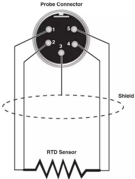
Figure 1 Probe connector wiring
A two-wire probe can also be used with the reference thermometer. It is connected by attaching one wire to both pins 1 and 2 of the plug and the other wire to both pins 4 and 5. If a shield wire is present it should be connected to pin 3. Accuracy may be significantly degraded using a two-wire connection because of lead resistance.
3.6.2 Measure Temperature
To make temperature measurements using your probe, the following parameters must be set up:
-
From the main screen, press the "MENU" button. Access the reference probe select menu (REF MENU|SELECT). Select "Probe 1" using the right or left arrow button. Press "ENTER" to accept the probe to be used.
-
To enable "Probe 1," use the ◀ or ▷ button to turn the reference probe "On." Press "ENTER" to accept the selection.
-
Press the "Setup" soft key (Main Menu: REF MENU|SETUP). In the reference probe setup menu, select "Probe 1" and press "ENTER".
-
Select the calibration type for the probe (ITS-90, CVD, or Res) using the ◁ or ▷ keys. Press “ENTER” to accept the calibration type.
-
Use the numeric keys to enter the serial number and calibration coefficients of the probe. Press “ENTER” after each parameter is entered to accept the new parameter value. Calibration coefficients can be found on a report of calibration that was shipped with your probe. If no coefficients can be found, contact the manufacturer or vendor of the probe for assistance. If the probe is out of calibration, Fluke Calibration offers calibration services. Contact an Authorized Service Center for assistance on obtaining a calibration for the probe.
-
After the reference probe has been enabled, the focus of the temperature display can be set. The focus is disabled if the reference probe is disabled. From the reference menu, press the "Focus" soft key (Main Menu: REF MENU|FOCUS). Use the ◀ or ▷ key to select reference focus. Press "ENTER" to accept the selection. The largest temperature on the display will now be the reference temperature.
4 Parts and controls
This section describes the exterior features of the Metrology Well.
4.1 Back panel
The following are found on the back of the Metrology Well (see Figure 2).
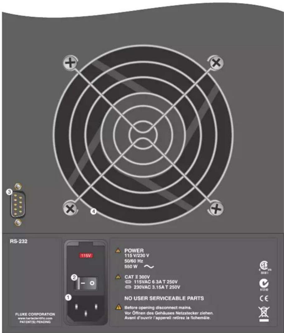
Figure 2 Metrology Well back panel view
Power Cord Plug (1)
The power supply cord attaches to the back panel. Plug the cord into an AC mains supply appropriate for the voltage range as specified in the specifications tables.
Power Switch (2)
The power switch is located on the power entry module of the unit at the bottom left of the back panel.
Serial Connector (3)
The serial connector is a 9-pin subminiature D type located on the back panel. The serial (RS-232) interface can be used to transmit measurements and control the operation of the Metrology Well.
Fan (4)
The fan is necessary to keep the internal components cool. Always make sure air can flow freely underneath and around the instrument.
4.2 Front panel
The following are found on the front of the Metrology Well (see Figure 3, on opposite page).
Display (1)
The display is a 320 x 240 pixel monochrome graphics LCD device with a bright CCFT backlight. The contrast can be adjusted using the △ or ▽ arrow buttons on the front panel. The display is used to show current control temperature, measurements, status information, operating parameters, and soft key functions.
Soft Keys (2)
The soft keys are the four buttons immediately below the display (labeled F1 to F4). The functions of the soft keys are indicated on the display above the buttons. The function of the keys may change depending on the menu or function that is selected.
Buttons (3)
The front panel buttons allow you to select menus, enter numeric data for operating parameters, move the cursor on the display, change the display layout, and adjust the contrast of the display.
Reference Thermometer Connection (-R models only) (4)
The 5-pin DIN connector on the front panel allows a reference probe to be attached to the unit for use with the reference thermometer function of the unit.
Switch Connectors (5)
The switch hold patented DWF connector posts are located on the right side of the front panel.
Block Temperature Indicator (U.S. Patent 7,561,058) (6)
The block temperature indicator lamp allows users to know when the block temperature is above 50^ C.
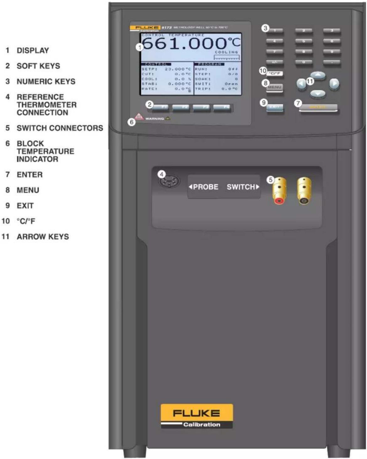
Figure 3 Metrology Well front panel view
4.3 Front Panel Display
The front panel display is shown in detail in Figure 3, on previous page and its features are described below.
Control Focus
The most recent block temperature measurement is shown in large digits in the box at the top of the screen. While viewing the main screen, the left arrow key enables the control focus view. The main control parameters are shown in the box at the bottom left of the screen. The current program selected is shown in the box at the bottom right of the screen.
Reference Focus (-R models only)
The most recent reference thermometer measurement is shown in large digits in the box at the top of the screen. While viewing the main screen, the right arrow key enables the reference focus view. The main control parameters are shown in the box at the bottom left of the screen and the current program selected is shown in the box at the bottom right of the screen.
Heating/Cooling Status
Just above the “PROGRAM” box there is a bar graph that will indicate HEATING, COOLING, or CUTOUT. This status graph indicates the current level of heating or cooling if the instrument is not in cutout mode.
Soft Key Functions
The four boxes at the bottom of the display indicate the functions of the soft keys (F1–F4). These functions change with each menu.
Editing Windows
While setting up and operating the instrument, you are often required to enter or select parameters. Editing windows appear on the screen when necessary to show the values of parameters and allow you to change them.
4.4 Front Panel Buttons
The functions of the front panel buttons are described below and shown in Figure 3, on previous page.
Soft Keys (2)
The four soft keys (F1–F4) just below the display are used to select menus or menu functions. The functions of the soft keys are indicated in text just above the soft keys on the display. The functions of the soft keys change depending on the selected menu. Pressing the “EXIT” key allows the user to exit from a sub-menu or window and returns to the previous menu or main screen.
Numeric Keys (3)
The ten number keys, the decimal point, and + / - keys are used to enter numeric data.
ENTER (7)
The “ENTER” key is used to enter a new parameter value or option or as a shortcut key to the set-point menu while viewing the main screen. When the value of any parameter is changed “ENTER” must be pressed to accept the new value. If the up/down arrow, exit or menu buttons are pressed before “ENTER”, the cursor will leave the parameter and any changes made to it will be canceled. Within a window with a list of parameters, pressing “ENTER” will also move the cursor down to the next parameter. If the cursor is at the bottom of the list, pressing “ENTER” with or without changing the parameter will exit the window. The “ENTER” button may also be used during some operations to affirm or continue with an action or choice.

NOTE: The “ENTER” button must always be pressed after changing a parameter to accept the new value or option.
Menu (8)
The menu key allows the user to access all parameter and settings menus. From the main menu, the user can use the soft keys to access submenus and functions.
EXIT (9)
The “EXIT” key is used to cancel an operation, exit a window, as a shortcut key to the cutout menu while viewing the main screen, or return from a lower menu to a higher menu. In any window, pressing “EXIT” will immediately exit the window and go to the previous window or menu. If a parameter is entered or changed and “EXIT” is pressed before “ENTER”, the change will be canceled. During some operations the “EXIT” key may be used to cancel the operation. If a cutout condition exists, press the “EXIT” key to access the Cutout menu. To reset the cutout, select the “RESET CUT-OUT” parameter and select “YES” using the ◀ or ▷ keys. Press “ENTER” to reset the Cutout.
°C/°F (10)
The “C/F” key allows the user to change the display units from Celsius to Fahrenheit and vice-versa while viewing the main screen.
Up/Down (△▽) Arrows (11)
The up and down arrow keys have three functions: move the cursor through a list of parameters in a window, scroll through parameters list that is longer than can be displayed, and, while viewing the main screen, change the contrast of the display.

NOTE: Parameter entry will abort if the up or down arrow key is pressed before "ENTER". Therefore, the up or down arrow keys can be used to cancel a parameter change.
Left/Right (◀ ▷) Arrows (11)
The left and right arrow keys have three functions: move from digit to digit while editing a parameter, select or change an option for some parameters, and change focus from control to reference or from reference to control. Remember, “ENTER” must always be pressed to save a new value or option selected.
4.5 Accessories
• 9170-CASE, Case, 9170–3 Carrying
- 9170-DCAS, Case, Transportation with wheels, 9170–3 Metrology Wells
• 9170-INSA, Insert, A, 9170, miscellaneous holes
• 9170-INSB, Insert, B, 9170, comparison holes
• 9170-INSC, Insert, C, 9170, four 0.25 inch holes
• 9170-INSD, Insert, D, 9170, metric, miscellaneous holes
- 9170-INSE, Insert, E, 9170, metric, 0.25 inch reference, miscellaneous holes
- 9170-INSF, Insert, F, 9170, metric, 0.25 inch reference, comparison holes
• 9170-INSG, Insert, G, 9170, EA testing
• 9170-INSY, Insert, Custom, 9170
• 9170-INSZ, Insert, Blank, 9170
• 9171-INSA, Insert, A, 9171, miscellaneous holes
• 9171-INSB, Insert, B, 9171, comparison holes
• 9171-INSC, Insert, C, 9171, four 0.25 inch holes
• 9171-INSD, Insert, D, 9171, metric miscellaneous holes
- 9171-INSE, Insert, E, 9171, metric,0.25 inch reference, miscellaneous holes
- 9171-INSF, Insert, F, 9171, metric, 0.25 inch reference, comparison holes
• 91710-INSG, Insert, G, 9171, EA testing
• 9171-INSY, Insert, Custom, 9171
• 9171-INSZ, Insert, Blank, 9171
• 9172-INSA, Insert, A, 9172, miscellaneous holes
• 9172-INSB, Insert, B, 9172, comparison holes
• 9172-INSC, Insert, C, 9172, four 0.25 inch holes
• 9172-INSD, Insert, D, 9172, metric miscellaneous holes
• 9172-INSE, Insert, E, 9172, metric, 0.25 inch reference, miscellaneous holes
- 9172-INSF, Insert, F, 9172, metric, 0.25 inch reference, comparison holes
• 9172-INSG, Insert, G, 9172, EA testing
• 9172-INSY, Insert, Custom, 9172
• 9172-INSZ, Insert, Blank, 9172
• 9173-INSA, Insert, A, 9173, miscellaneous holes
• 9173-INSB, Insert, B, 9173, comparison holes
• 9173-INSC, Insert, C, 9173, four 0.25 inch holes
• 9173-INSD, Insert, D, 9173, metric miscellaneous holes
• 9173-INSE, Insert, E, 9173, metric, 0.25 inch reference, miscellaneous holes
• 9173-INSF, Insert, F, 9173, metric, 0.25 inch reference, comparison holes
• 9173-INSG, Insert, G, 9173, EA testing
• 9173-INSY, Insert, Custom, 9173
• 9173-INSZ, Insert, Blank, 9173
Insert"A"Insert"B"Insert"C"
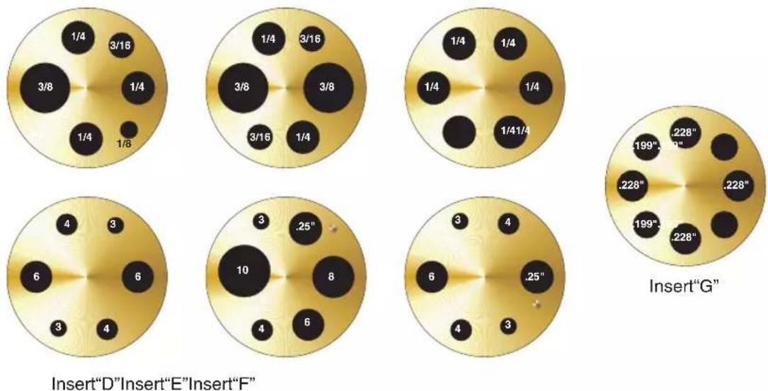
Figure 4 Metrology Well insert options. Probe sizes indicated in inches for A, B, and C, and millimeters for sleeves D, E, and F except for 0.25 inch reference holes in E and F.
5 Controller operation
This chapter discusses in detail how to operate the Metrology Well temperature controller or reference thermometer using the front control panel. Using the front panel keys and liquid crystal display (LCD) the user may monitor the well temperature, set the temperature set-point in ^ C or ^ F, monitor the heater output power, set the cutout set-point, set the operating parameters, and configure the communication interface. A diagram of the full menu structure can be found at the end of this section. When active, menu keys are selected using the soft keys (F1-F4).
5.1 Main Screen
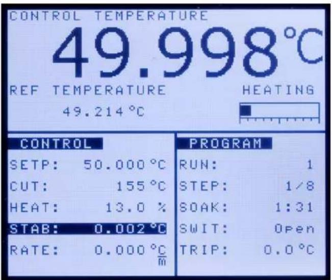
Figure 5 Main screen display
The LCD on the front panel allows direct viewing of the control temperature (actual well temperature), reference thermometer temperature, heating or cooling power, current set-point information and current program information. The temperature displayed is either in ^ C or ^ F. The displayed temperature units can easily be changed by pressing the C/F key on the front panel.
CONTROL TEMPERATURE
This is the temperature of the block as measured by the control sensor. The controller heats or cools the block to force the control temperature equal to the set-point.
REF TEMPERATURE
This is the temperature measured by an external reference thermometer attached to the Probe input. It can be displayed in large digits by setting the focus using the left and right buttons or the FOCUS menu function.
HEATING, COOLING, CUTOUT
This shows the status of heating or cooling or the cutout when activated. The gauge below indicates the relative heating or cooling power.
CONTROL - SETP (Set-point)
This is the current set-point.
CONTROL - CUT (Cutout)
This is the current cutout set-point.
CONTROL - HEAT/COOL
This shows the relative heating or cooling power (duty cycle) in percent.
CONTROL - STAB (Stability)
This shows the stability of the block. It is measured over two minutes and is calculated as twice the standard deviation of individual control temperature measurement during that time. When the stability is within the set limit this line is highlighted.
CONTROL - RATE
This shows the rate of change of the control temperature. It is measured over two minutes and is calculated as the average slope.
PROGRAM - RUN
This shows the active sequence (ramp-and-soak) program number or off if the program is stopped.
PROGRAM - STEP
This shows the set-point step number and total points of the sequence program.
PROGRAM - SOAK
This shows the soak timer for the sequence program. It is reset to the set soak minutes when the sequence advances to the next set-point, counts down hours and minutes when stability is reached, and advances the set-point when 0:00 is reached.
PROGRAM - SWIT (Switch)
This shows the current state of the switch attached to the switch test inputs, open or closed.
PROGRAM - TRIP
This shows the control temperature at which the switch last changed states.
SWITCH - TEST
This shows the active switch test number or off is the test is stopped.
SWITCH - CYCL (Cycle)
This shows the current test cycle or off is the test is stopped.
SWITCH - CLOS (Close)
This shows the control temperature at which the switch last closed during the test.
SWITCH - OPEN
This shows the control temperature at which the switch last opened during the test.
5.2 Main Menu
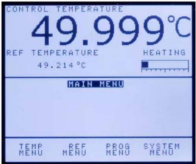
Figure 6 MAIN MENU
The main menu allows access to all main submenus which allow the user to setup the instrument as desired and to change system parameters as needed.
5.2.1 Temp Menu
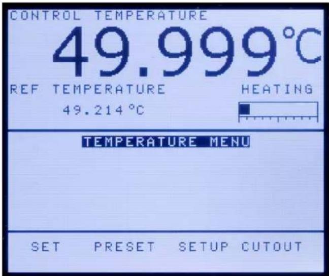
Figure 7 TEMPERATURE MENU
The Temp Menu (TEMPERATURE MENU) contains all Metrology Well functions related to temperature setup.
5.2.1.1 Set
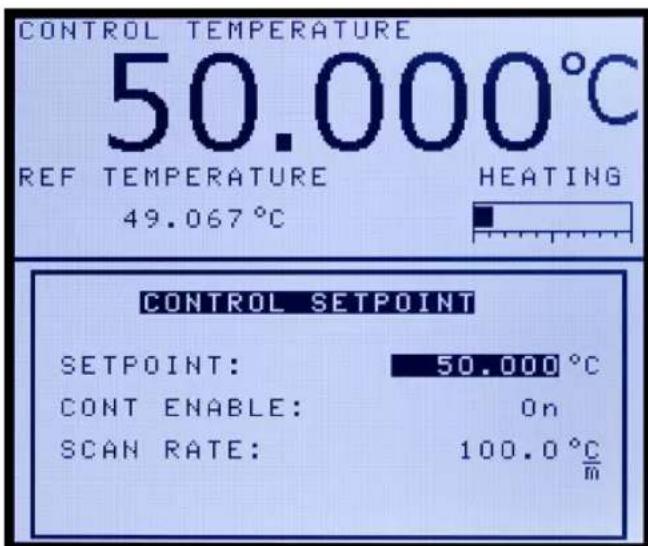
Figure 8 CONTROL SETPOINT menu
The Set (CONTROL SETPOINT) menu allows the user to change the set-point, enable or disable active heating or cooling, and specify the heating or cooling rate of the instrument. This menu window may be accessed quickly by pressing “ENTER” from the main screen.
SETPOINT
The Setpoint (Set-point) parameter can be set to any value within the range and with resolution as given in the specifications. Be careful not to exceed the safe upper temperature limit of any device inserted into the well. The soft cutout should be properly adjusted to help prevent this occurrence.
CONT ENABLE

NOTE: Each time the instrument is turned off and back on, the "CONT ENABLE" parameter is set to "Off".
The Cont Enable (Control Enable) parameter controls whether the instrument heats or cools. This parameter must be set to "On" for the instrument to heat or cool. Use the right or left arrow keys to select "On" (the instrument heats or cools) or "Off" (disables heating and cooling).
SCAN RATE
The Scan Rate parameter can be set such that when the set-point is changed, the Metrology Well heats or cools at a specified rate (degrees per minute) until it reaches the new set-point.
The scan rate can be set from 0.1 to 500 °C/min (0.2 to 900 °F/min). However, the maximum scan rate is limited by the natural heating or cooling rate of the instrument, which is often less than 100 °C/min, especially when cooling.
The scan rate can be adjusted using the numeric keys. Once the scan rate has been set, press "ENTER" to set the new scan rate.
5.2.1.2 Preset
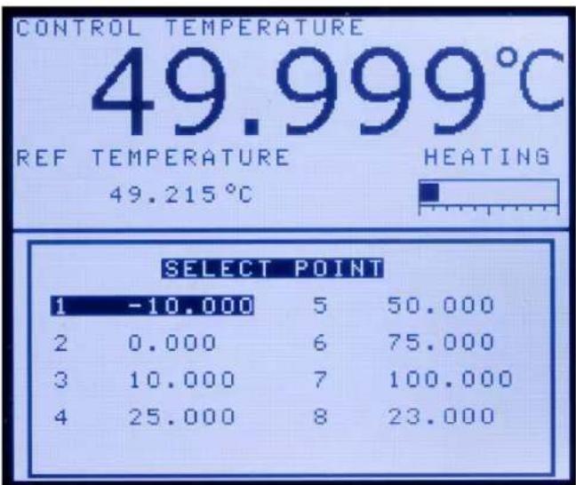
Figure 9 SELECT POINT menu
The Preset (SELECT POINT) menu allows the user to quickly recall and conveniently change the instrument to a previously programmed set-point. The arrow keys can be used to select a preset point. The numeric keys 1–8 may be used to quickly select a set-point. Once the desired point is selected, press “ENTER” to accept the selection. The instrument will now heat or cool as needed to achieve the new set-point.
5.2.1.3 Setup
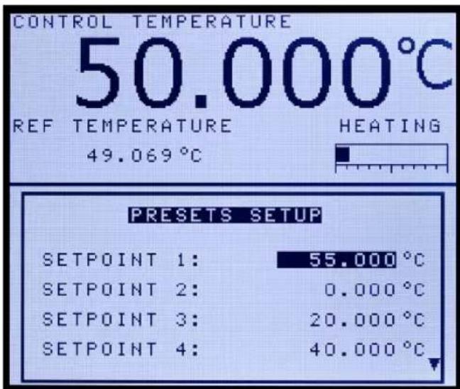
Figure 10 PRESETS SETUP menu
The Setup (PRESETS SETUP) menu allows the user to set up all eight preset set-points stored in the controller. Setpoints can be quickly selected using the Preset function. Use the Up/Down arrows to scroll through the set-points. The number keys can be used to enter the desired set-point value. Once the desired value has been set, press the "ENTER" key to accept the value. Repeat the previously described procedure until all points are set to the desired values.
5.2.1.4 Cutout
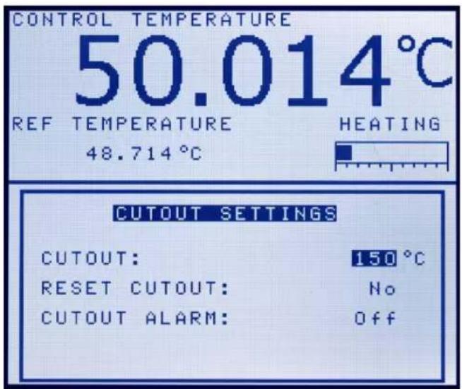
Figure 11 CUTOUT SETTINGS menu
The Cutout (CUTOUT SETTINGS) menu allows the user to set the cutout temperature and to reset the cutout from the display. The cutout temperature is programmable by the operator from the front panel of the controller. As a protection against software or hardware fault or user error, the calibrator is equipped with the adjustable cutout device that shuts off power to the heat source if the well temperature exceeds a set value. This feature protects the instrument and probes from excessive temperatures.
If the cutout is activated because of excessive well temperature, power to the heat source shuts off and the instrument cools. The heat source remains in cutout mode and active heating and cooling is disabled until the user manually resets the cutout. If the over-temperature cutout has been triggered, the instrument displays “CUTOUT” above the duty cycle bar graph, which indicates a cutout condition. The instrument remains in cutout mode until the temperature is reduced and the cutout is reset. The well temperature must drop a few degrees below the cutout set-point before the cutout can be reset.
For safety reasons, the cutout only has one mode — manual reset. Manual reset mode means the cutout must be reset by the operator after the temperature falls below the set-point.
To quickly access the reset cutout function press the "EXIT" key from the main screen.
CUTOUT
The Cutout parameter can be set to any temperature over the range of the instrument. The cutout should be set within 5-10° of the safety limit of the equipment being calibrated or used with the Metrology Well.
RESET CUTOUT
If the Metrology Well exceeds the temperature set in the soft cutout menu or if it exceeds the maximum operating temperature of the instrument, a cutout condition occurs. If this happens, the instrument enters cutout mode and will not actively heat or cool until the user accesses this parameter and selects "Yes".
CUTOUT ALARM
The Cutout Alarm parameter can be set to ON or OFF. If the Cutout Alarm is ON when a cutout condition exists, the alarm will sound every 15 seconds.
5.2.2 Ref Menu (-R instruments only)
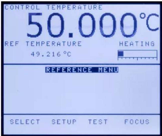
Figure 12 REFERENCE MENU
The Ref Menu (REFERENCE MENU) allows all parameters related to the reference thermometer function of the instrument to be accessed. The parameters found in this menu affect the performance, accuracy, and display type of thermometers used.
5.2.2.1 Select
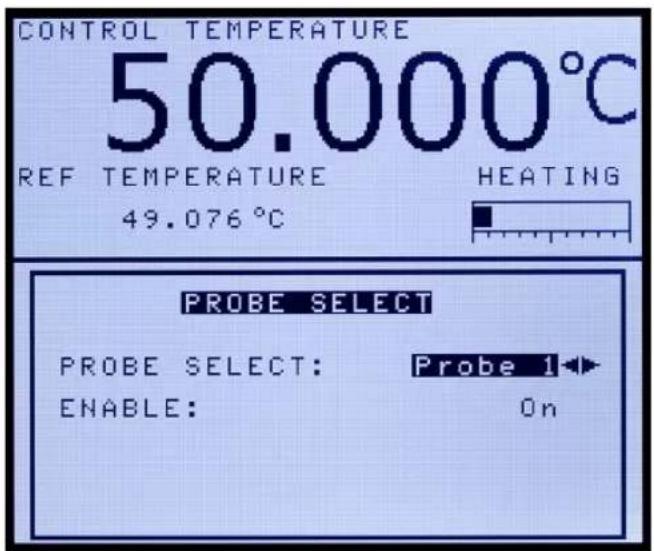
Figure 13 PROBE SELECT menu
The Select menu (PROBE SELECT) allows the user to select and enable the probe that will be used as the reference probe. Parameters for two probes can be stored in the instrument. If the proper probe is not selected, readings acquired from the thermometer will not be accurate. It is important that the proper probe be selected when using the reference thermometer.
PROBE SELECT
The Select parameter can be set to Probe 1 or Probe 2. The probe being used with the instrument should be selected from this menu.
ENABLE
The Enable parameter enables or disables the reference thermometer function of the instrument. This function should be disabled when not in use. In order for the reference probe to function, the reference probe function of the instrument needs to be enabled from this menu. By selecting “On”, the instrument reads the temperature or resistance of the probe connected to the reference input on the front of the instrument.
5.2.2.2 Setup
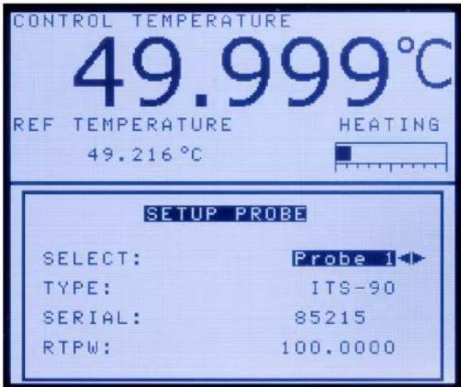
Figure 14 SETUP PROBE menu
The Setup (SETUP PROBE) menu is used to set up the reference probe(s). The instrument is only compatible with Platinum Resistance Thermometers (PRTs) with ITS-90 or Callendar Van-Dusen calibrations. No other types of coefficients are supported.
The probe serial number and coefficients can be found on the calibration certificate that was shipped with the probe. If the probe requires calibration, contact an Authorized Service Center to inquire about calibration services offered by Fluke Calibration.
While editing the reference probe serial number, there are two soft keys, BACK and DONE. BACK acts as a “backspace” key to allow an incorrect digit or character to be deleted. The DONE key causes the entered serial number to be accepted and returns to the main reference probe editing window.
SELECT
The SELECT parameter is used to choose which probe is to be setup.
TYPE (ITS-90)
The TYPE parameter can be ITS-90 or Callendar Van-Dusen. The ITS-90 option is for PRTs calibrated and characterized using the International Temperature Scale of 1990 (ITS-90) equations. Subranges 4, and 7 through 11 are supported. The parameters that appear when ITS-90 is selected are “Serial” (Serial Number), “RTPW”, “COEF A”, “COEF B”, “COEF C”, “COEF A4”, and “COEF B4”. These should be set with the corresponding values that appear on the calibration certificate of the PRT. The parameter “RTPW” takes the triple point of water resistance, often labeled “R0” or “R(273.16K)” on the certificate. Parameters “COEF A”, “COEF B”, “COEF C” take the a, b and c coefficients where n is a number from 7 to 11. Parameters “COEF A4” and “COEF B4” take the a₄ and b₄ coefficients on the certificate. Any ITS-90 parameter of the instrument that does not have a corresponding coefficient on the PRT’s certificate must be set to 0.
The following table shows which parameter to set for each of the coefficients that may appear on the certificate. The example that follows demonstrates how to set the ITS-90 parameters for certain cases.

NOTE: If the certificate has two sets of coefficients, one set for “zero-power” calibration and one set for 1 mA calibration, use the coefficients for the 1 mA calibration.
Table 4 Matching Certificate Values to 917X ITS-90 Coefficients
| 917X ITS-90 Coefficient Certificate Value |
| COEF A a7, a8, a9, a10, or a11 |
| COEF B b7, b8, b9, or 0 |
| COEF C c7 or 0 |
| COEF A4 a4 |
| COEF B4 b4 |
Example 1:
A PRT was calibrated to ITS-90 and its calibration certificate states values for coefficients Rtpw, a_4 , b_4 , a_8 , and b_8 . Set the instrument's parameters with values from the certificate as follows.
Table 5 Setting Coefficients Rtpw, a8, b8, a4, and b4
| 917X Coefficient Certificate Value |
| RTPW Rtpw |
| COEF A a8 |
| COEF B b8 |
| COEF C 0 |
| COEF A4 a4 |
| COEF B4 b4 |
TYPE (CVD)
The CVD (Callendar-Van Dusen) conversion is for RTD probes that use the Callendar-Van Dusen equation:
$$ r (t [ ^ {\circ} \mathrm{C} ]) = \left{ \begin{array}{l l} R _ {0} \left{1 + \alpha [ t - \delta \frac {t}{1 0 0} \left(\frac {t}{1 0 0} - 1\right) \right} & t \geq 0 \ R _ {0} \left{1 + \alpha \left[ t - \delta \frac {t}{1 0 0} \left(\frac {t}{1 0 0} - 1\right) - \beta \left(\frac {t}{1 0 0} - 1\right) ^ {3} \right] \right} & t < 0 \end{array} \right. $$
The parameters that appear when CVD is selected are “Serial” (Serial Number), “R0”, “ALPHA”, “DELTA” and “BETA”, which can be set by the user. For IEC-751, DIN-
43760 or ASTM E1137 sensors, the coefficients for R0, ALPHA, DELTA, and BETA are 100.0, 0.00385055, 1.499786, and 0.10863 respectively.
Some probes may be provided with A, B, and C coefficients for the Callendar-Van Dusen equation in the following form:
$$ r (t) \mathbb {C} = \left{ \begin{array}{l l} R A (t B t + ^ {2}) & \geq 0 \ R A [ B t C t t + ^ {2} - (1 0 0) ^ {3} ] & < 0 \end{array} \right. $$
The A, B, and C coefficients can be converted to Alpha, Beta and Delta coefficients using the following equation:
$$ \alpha = A + 1 0 0 B \quad \delta = - \frac {1 0 0}{\frac {A}{1 0 0 B} + 1} \quad \beta = - \frac {1 0 ^ {8} C}{A + 1 0 0 B} $$
TYPE (Res)
The Res (Resistance) option displays the resistance, in ohms, of the selected reference probe.
5.2.2.3 Test
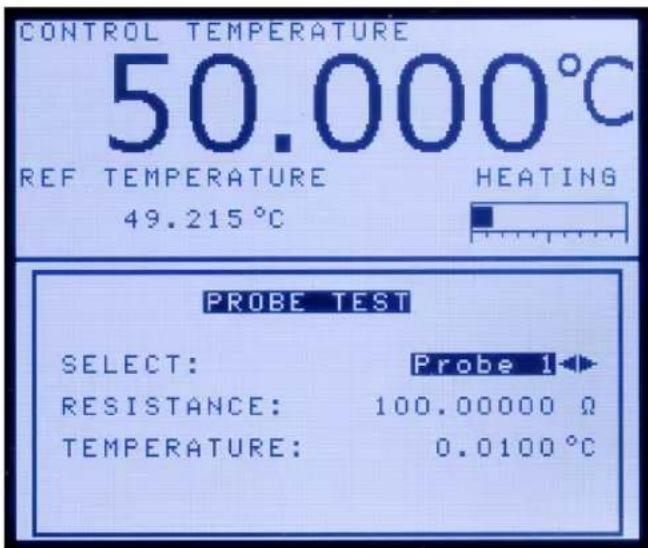
Figure 15 PROBE TEST menu
The Test (PROBE TEST) menu is used to test the parameters for a given probe. To test the parameters of the selected probe, input a test resistance and read the calculated temperature for that resistance.
SELECT
The SELECT parameter is the probe number of the probe to be tested.
RESISTANCE
The test resistance of the sensor should be entered in the RESISTANCE parameter.
TEMPERATURE (view only)
The TEMPERATURE parameter is the calculated temperature of the current probe based on the resistance set in the resistance parameter. This parameter is for display only and cannot be changed.
5.2.2.4 Focus (-R instruments only)
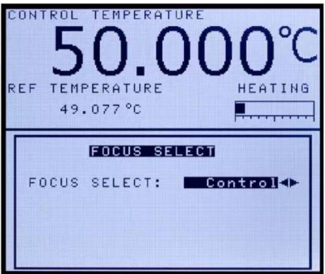
Figure 16 FOCUS SELECT menu

NOTE: The Focus (FOCUS SELECT) menu is only active if the reference thermometer option is installed and the reference thermometer function enabled.
This menu determines which temperature, control or reference thermometer, is displayed as the largest text on the screen.
FOCUS SELECT
Select “Control” and the control temperature of the heat source is displayed as the largest text on the screen. Select “Reference” and the reference thermometer temperature is displayed as the largest text on the screen..

NOTE: From the main screen, the right or left arrow keys set the control and reference focus respectively.
5.2.3 Prog Menu
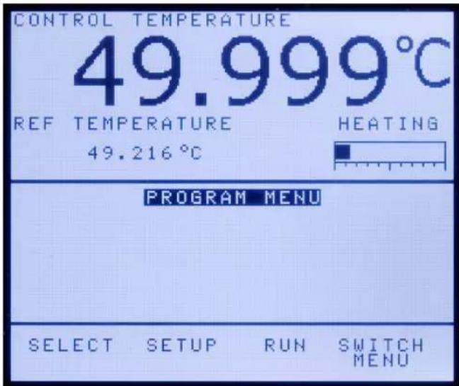
Figure 17 PROGRAM MENU
The Prog Menu (PROGRAM MENU) allows the user to access the ramp and soak feature. This feature automatically cycles the Metrology Well between temperatures while holding at each temperature for the length of time set by the user.
5.2.3.1 Select
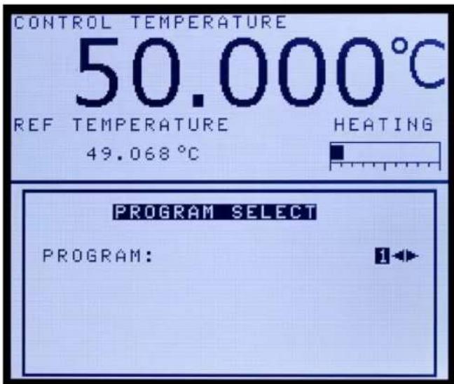
Figure 18 PROGRAM SELECT menu
The Select (PROGRAM SELECT) menu is used to set up and store up to four programs. One of the four programs available can be selected in this menu.
5.2.3.2 Setup
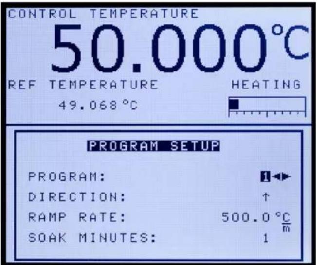
Figure 19 PROGRAM SETUP menu
The Setup (PROGRAM SETUP) menu allows specific settings to be set up and stored for each program (1-4). If desired, each program can have unique settings.
PROGRAM
The PROGRAM parameter is used to set up a program. Select the proper program number and press "ENTER".
DIRECTION
The DIRECTION parameter controls whether the set-points are sequenced in one direction or both directions before the sequence is repeated. If the both directions option is selected, the program sequences from the first set-point to the last and then reverses direction sequencing from the last to the first.
RAMP RATE
The RAMP RATE parameter controls the scan rate for the programmed test. Refer to the “Scan Rate” section for more information on the ramp rate.
SOAK MINUTES
The SOAK MINUTES parameter is the number of minutes that each of the program set-points is maintained. The time starts when the temperature settles to within the specified stability. The stability limit is set in the MEAS window.
CYCLES
The CYCLES parameter is the number of times that the program is repeated.
POINTS
The POINTS parameter is the number of set-points defined for a given program. The number of set-points for each program can be set from 1 to 8 and vary depending on the needs of the user. Set the maximum number of set-points needed for the program selected. Once the number of set-points is selected, press “ENTER” to accept the new setting.
PROGRAM
The PROGRAM parameter appears and displays the number of the selected program for which set-points are being setup. Once the number of set-points has been chosen, the set-point setup is active and each set-point can be set up as follows:
- Use the up/down arrows to select the set-point(s) that need to be adjusted.
- Use the numeric keys to enter the desired temperature for each set-point.
- Press "ENTER" to accept the new temperature.
- Repeat steps 1-3 for all other set-points.
5.2.3.3 Run
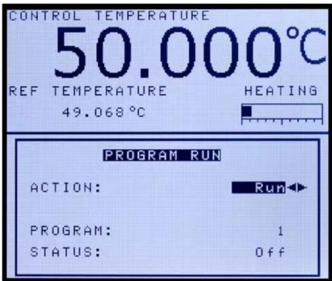
Figure 20 PROGRAM RUN menu
The Run (PROGRAM RUN) menu controls the programmed test. You may choose between three options: start the program from the beginning, continue the program from the point where it was stopped, or stop the program.
ACTION
The ACTION parameter allows a program to be started, continued or stopped.
To start a program, use the right/left arrow keys to select "Run" and press "ENTER". The program runs until finished or until the user changes the program action to "Stop".
To stop a program, use the right or left arrow keys to select "Stop" and press "ENTER". The program stops until the user continues or restarts the program.
To continue a previously stopped program, use the right or left arrow keys to select "Cont" and press "ENTER". The program starts at the same point it was previously stopped.
PROGRAM (view only)
The PROGRAM parameter displays the current program in use.
STATUS (view only)
The STATUS parameter displays the status of the current program in use. If a program is enabled and running, this parameter displays “On”, otherwise “Off” is displayed.
5.2.3.4 Switch Menu
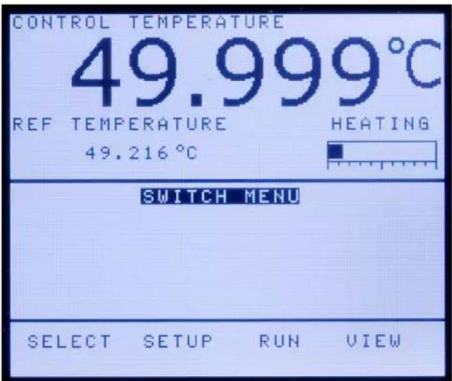
Figure 21 SWITCH MENU
The SWITCH MENU is used to select, set up, execute and view the results of switch tests. The switch test function allows thermal switches to be tested for open and/or close temperatures. Four different test setups can be setup and stored in the controller.
The switch test temperature shows what the temperature of the well was when the switch changed from its normal position to its active position and vice versa. Operation of the switch test feature is outlined below.
5.2.3.4.1 Select
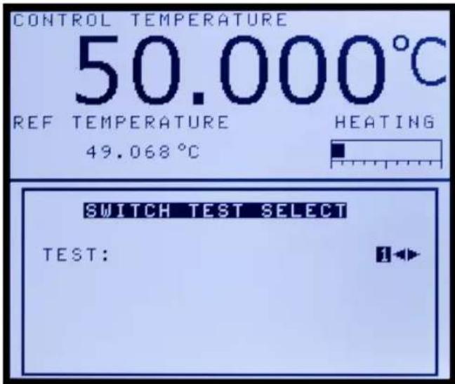
Figure 22 SWITCH TEST SELECT menu
The Select (SWITCH TEST SELECT) menu allows the user to select one of four test setups. Once the desired test number is selected, press "ENTER" to accept the selection.
5.2.3.4.2 Setup
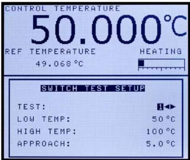
Figure 23 SWITCH TEST SETUP menu
The Setup (SWITCH TEST SETUP) menu allows each of the four available tests to be setup and customized by the user.
TEST
The TEST parameter requires the user to select the test to be programmed. Select one of the four tests to configure and press “ENTER”.
LOW TEMP
The LOW TEMP parameter is the temperature at which the Metrology Well heats or cools, in order to begin testing if the test is just starting or the temperature at which the instrument begins to heat to start a cycle.
HIGH TEMP
The HIGH TEMP parameter is the temperature during a cycle at which the Metrology Well begins to cool at the rate specified in “Ramp Rate”.
APPROACH
The APPROACH parameter determines when the system scan rate is used and when the switch test ramp rate is used to limit scan rate. During the test, the controller uses the system scan rate until the temperature is within the approach temperature of either the high temp or low temp parameters.
RAMP RATE
The RAMP RATE parameter is the rate at which the instrument heats or cools once the low or high limit is reached. The ramp rate affects the accuracy with which the opening/closing of a thermal switch may be measured. The ramp rate should be selected by the user such that the opening/closing of the switch can accurately be measured.
CYCLES
The CYCLES parameter determines how many times the instrument heats and cools allowing a thermal switch or batch of switches to be tested.
5.2.3.4.3 Run
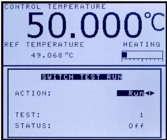
Figure 24 SWITCH TEST RUN menu
The Run (SWITCH TEST RUN) menu allows the user to start and stop switch tests.
ACTION
The current test can be started or stopped from a previous state using the ACTION parameter.
TEST (view only)
The current selected test number is displayed in the TEST parameter.
STATUS (view only)
The STATUS parameter displays the status of the current switch test. If a test is enabled and running, the status parameter displays "On", otherwise "Off" is displayed.
5.2.3.4.4 View (view only)
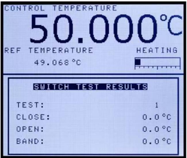
Figure 25 SWITCH TEST RESULTS menu
The View (SWITCH TEST RESULTS) menu allows the user to view the results of the last cycle of a switch test.
TEST
The TEST parameter displays the number of the selected test.
CLOSE
The CLOSE parameter displays the temperature at which the switch closed.
OPEN
The OPEN parameter displays the temperature at which the switch opened.
BAND
The BAND parameter displays the absolute difference between the open and close temperature.
5.2.3.4.5 Switch wiring and example
The thermal switch or cutout is wired to the calibrator at the two terminals at the front of the Metrology Well calibrator labeled “Switch Test”. The polarity of the switch wires does not matter. Internally, the black terminal connects to ground. The red terminal connects to +5V through a 10 kΩ resistor. The calibrator measures the voltage at the red terminal and interprets +5V as open and 0V as closed.
Example:
A thermal switch opens and closes at about 100 °C , but the accuracy, repeatability, and dead band of the switch need to be verified. The Switch program feature (described in preceding sections) can be used to test the switch. Test results are shown on the main screen during and after the test. To set up the test, do the following:
- Connect the switch wires to the “Switch” terminals on the front of the Metrology Well (as described previously) and place the switch in the well. Match the outside diameter of the switch with a similar sized hole of the Metrology Well insert.

CAUTION: The switch, switch wires, switch components and/or switch accessories can be damaged if the Metrology Well exceeds their temperature limits.
- Set up test "1" at MAIN|PROG MENU|SWITCH MENU|SETUP (see previous sections for more information on switch test setup). Set LOW TEMP to 80 °C, HIGH TEMP to 120 °C, RAMP RATE to 1.0 °C, APPROACH to 5.0 °C, and CYCLES to 3.

NOTE: The LOW TEMP and HIGH TEMP in this example have been set to 100 °C ± 20 °C, but some switches may require a much wider window. The window gives the instrument an approximation of where the switch will open and close. If the window of LOW TEMP and HIGH TEMP is too narrow, the switch test may abort before determining the characteristics of the switch.

NOTE: The APPROACH TEMP, RAMP RATE and CYCLES should be set such that the highest desired accuracy of the switch temperatures is obtained. APPROACH should not be set such that (HIGH TEMP - APPROACH) <= LOW TEMP or “Settings conflict” is displayed when trying to start a switch test and the test will not run.

NOTE: Depending on the mass and/or diameter the switch, there may be a significant lag time in how fast the switch heats up or cools with respect to the block of the Metrology Well. For larger mass and/or diameter switches, a lower RAMP RATE (0.1-0.5 °C) and a higher APPROACH (5-10 °C) can produce better results. More cycles may give a better average of when the switch opens and closes, but a minimum of 2 cycles should be used when running a switch test.
- Select test "1" at MAIN|PROG MENU|SWITCH MENU|SELECT using the arrow keys and press "ENTER".
-
Start the switch test at MAIN|PROG MENU|SWITCH MENU|RUN by selecting Run and pressing "ENTER".
-
Return to the main screen to view the results of the current test by pressing and holding the "EXIT" key (CLOS = switch close temperature, OPEN = switch open temperature) or at MAIN|PROG MENU|SWITCH MENU|VIEW (CLOSE = switch close temperature, OPEN = switch open temperature, BAND = difference between open and close temperature).
-
Once the test is finished, the data can be recorded, or the test can be run again by repeating the steps above.
5.2.4 System Menu
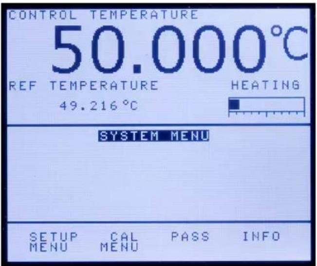
Figure 26 SYSTEM MENU
The controller has a number of configuration and operating options. It also has calibration parameters that are programmable via the front panel. These are accessed from the System Menu. The configuration parameters included are display parameters, security parameters and passwords, probe parameters, operating parameters, serial interface parameters, reference thermometer calibration parameters, Metrology Well sensor calibration parameters, and controller calibration parameters. The menus are selected using the soft keys (F1-F4) on the front panel when the SYSTEM MENU is active.
5.2.4.1 Setup menu
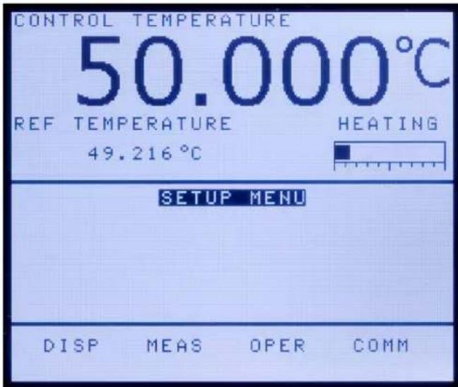
Figure 27 SETUP MENU
The SETUP MENU contains submenus that insure the proper operation of the instrument. System settings should only be adjusted by qualified and trained personnel.
5.2.4.1.1 Disp
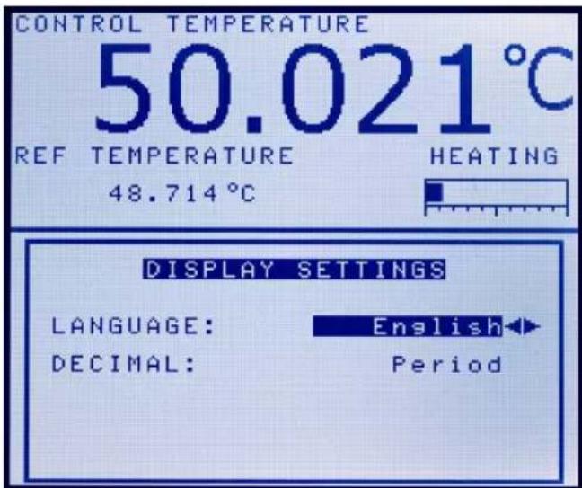
Figure 28 DISPLAY SETTINGS menu
The Disp (DISPLAY SETTINGS) menu allows the user to change the display language and decimal separator.
LANGUAGE
The LANGUAGE parameter is used to set the display language. The instrument supports a limited number of languages. Use the right or left arrow key to select the
preferred language and press “ENTER” to accept the selection. The user needs to exit from the DISP menu window in order for the change in language selection to take affect.

NOTE: If the wrong language is selected, return to the Main Screen by holding EXIT for a few seconds. Once the Main Screen is displayed, simultaneously press and hold F1 and F4 to return to English.
DECIMAL
The DECIMAL parameter is used to determine the decimal separator, a comma or a period. Select the desired decimal separator using the right or left arrow key and press "ENTER" to accept the selection.
5.2.4.1.2 Meas
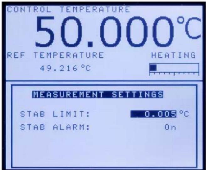
Figure 29 MEASUREMENT SETTINGS menu
The Meas (MEASUREMENT SETTINGS) menu is used to set the stability limit and alarm.
STAB LIMIT

NOTE: The Metrology Well should not be expected to operate better than the stability specification set forth in the Specifications section of this guide.
Therefore, the minimum setting of the stability limit should not be less than the stability specification.
The STAB LIMIT parameter allows the instrument to notify the user when it has achieved the stability limit set in this parameter. There are two notifications: visual and audible. The visual notification is always active. When the instrument is operating
within the stability limit, the stability parameter on the main screen remains highlighted once the instrument is within the given specification, otherwise the parameter is not be highlighted. The audible, if enabled, alerts the user once per set-point when the instrument achieves the set stability limit. Use the numeric keys to set the desired stability limit and press “ENTER” to accept the new stability limit.
Example:
A specific calibration process requires the instrument to operate within ±0.1^ . “0.1” would be entered into the stability limit parameter. When the instrument’s stability is within ±0.1^ , “STAB: X.XXX°C” is be highlighted and the audible alarm (if enabled) notifies the user that the instrument is operating within ±0.1^ . Use the numeric keys to set the desired stability limit and press “ENTER” to accept the new stability limit.
STAB ALARM
The audible alarm described in STAB LIMIT is turned on or off using the STAB ALARM parameter. Select the either "On" or "Off" using the ◀ or ▷ arrow keys and press "ENTER" to accept the selection.
5.2.4.1.3 Oper
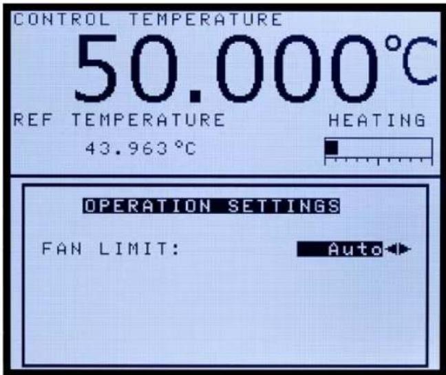
Figure 30 OPERATION SETTINGS menu
The Oper (OPERATION SETTINGS) menu allows the user to set up the limit for the maximum speed of the fan. The FAN LIMIT parameter can be set to Auto, Medium or Low. The Auto setting allows the instrument to operate at maximum efficiency for the chosen set-point. The instrument may be noisier as the fan moves at different speeds through the temperature range improving the performance. At low temperature settings, the fan operates at its fastest speed. At high temperatures, the fan operates at a lower speed.

NOTE: The Low setting is quieter, but decreases scan rate, reduces low temperature performance and may prevent the instrument from fully meeting all specifications. The Medium setting falls in the middle of Auto and Low. The Medium setting does not allow the fan to operate at its fast speed, but does allow it to operate at slower speed when applicable.
5.2.4.1.4 Comm
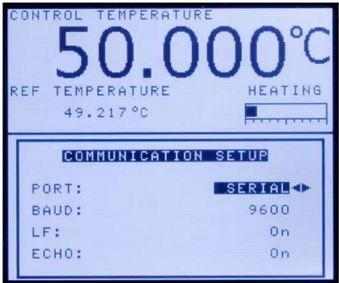
Figure 31 COMMUNICATION SETUP menu
The Comm (COMMUNICATION SETUP) menu contains the serial interface parameters. The parameters in the menu are — PORT, BAUD rate, LF, ECHO, SERIAL PERIOD and PRINT.
PORT
The PORT parameter can be set to "SERIAL" or "ERRORS". The serial port references the serial interface port and its parameters are listed below. The errors port reports errors obtained by the controller to the screen.
BAUD
The BAUD parameter determines the serial communications transmission rate or baud rate.
BAUD may be programmed to 1200, 2400, 4800, 9600, 19200, or 38400 baud.
LF
The LF (Line Feed) parameter enables (On) or disables (Off) transmission of a line feed character (LF, ASCII 10) after transmission of any carriage-return. The “LF”
default setting is on. The line feed parameter can be turned on or off as needed by the user.
ECHO
The ECHO parameter mode may be set to "On" or "Off". With echo "On", any commands received by the thermometer via the serial interface are immediately echoed or transmitted back to the device of origin. With echo "Off", the commands are executed but not echoed. The default setting is "On". The mode may be changed using the left or right arrow keys and pressing "ENTER".
SER PER
The SER PER (Serial Period) parameter is the interval at which data is transmitted by the instrument to a computer through the serial interface. The serial period is the time period, in seconds, between temperature measurements transmitted from the serial interface. For example, if the sample rate is set to 5, the instrument transmits the current temperature measurement approximately every 5 seconds.
The PRINT parameter enables or disables printing the control temperature and power through the serial port.

NOTE: If PRINT is set to "Off", samples are not transmitted automatically through the serial interface.
5.2.4.2 Cal Menu
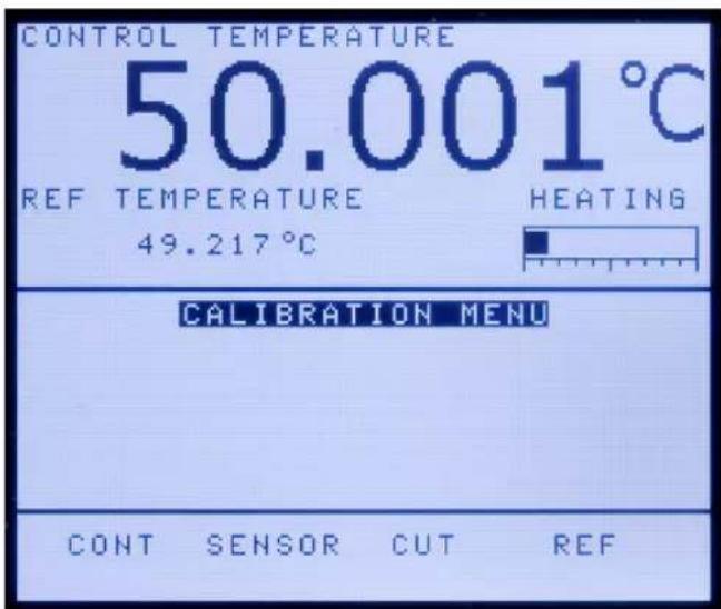
Figure 32 CALIBRATION MENU

CAUTION: Calibration parameters must be correct for the instrument to function properly.
The Cal Menu (CALIBRATION MENU) is used to access controller parameters and the reference thermometer calibration parameters. Access to the controller and reference thermometer calibration parameters is protected by a password. Calibration parameters are programmed at the factory when the instrument is calibrated. These parameters may be adjusted to improve the accuracy of the instrument by qualified personnel. Instructions for calibration can be found in the “Calibration of your Metrology Well” section of this guide.
5.2.4.2.1 Cont
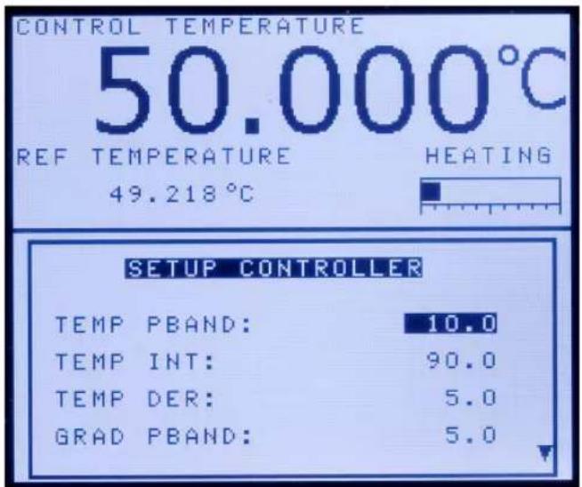
Figure 33 SETUP CONTROLLER menu

CAUTION: DO NOT change the values of the control parameters from the factory set values. The correct setting of these parameters is important to the safe and proper operation of the calibrator.
The parameters in the Cont (SETUP CONTROLLER) menu are set at the factory and must not be altered. The correct values are important to the accuracy and proper and safe operation of the calibrator. Access to these parameters is protected by a password and is available to the user in the event that the controller's memory fails. If this happens, the user may restore these values to the factory settings. These constants and their settings are listed in the Report of Calibration shipped with the instrument.
TEMP PBAND
The TEMP PBAND parameter is the main zone proportional band and the gain in ^ that the instrument's proportional-integral-derivative (PID) controller uses for main zone control.
TEMP INT
The TEMP INT parameter is the main zone integral, which is the integration time in seconds that the instrument's PID controller uses for main zone control.
TEMP DER
The TEMP DER parameter is the main zone derivative, which is the derivative time in seconds that the instrument's PID controller uses for main zone control.
GRAD PBAND
The GRAD PBAND parameter is the gain in ^ that the instrument's PID controller uses for gradient control.
GRAD INT
The GRAD INT parameter is the integration time in seconds that the instrument's PID controller uses for gradient control.
5.2.4.2.2 Sensor
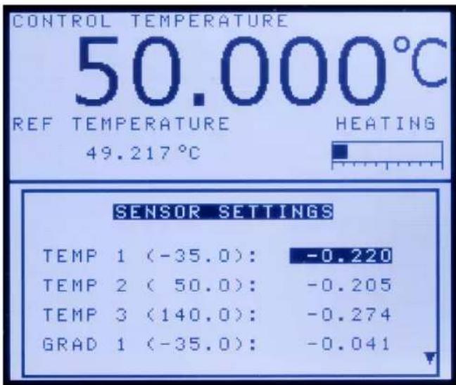
Figure 34 SENSOR SETTINGS menu
The Sensor (SENSOR SETTINGS) menu parameters are set at the factory and must only be altered by qualified personnel. The correct values are important to the accuracy and proper and safe operation of the calibrator. Access to these parameters is protected by a password and is available to the user in the event that the controller's memory fails. If this happens, the user may restore these values to the factory settings. These constants and their settings are listed in the Report of Calibration shipped with the instrument.
TEMP 1
The TEMP 1 parameter is the offset in ^ for the display accuracy at the 1st calibration point.
TEMP 2
The TEMP 2 parameter is the offset in °C for the display accuracy at the 2nd calibration point.
TEMP 3
The TEMP 3 parameter is the offset in °C for the display accuracy at the 3rd calibration point.
GRAD 1
The GRAD 1 parameter is the offset in ^ C for the axial gradient at the 1st gradient calibration point.
GRAD 2
The GRAD 2 parameter is the offset in ^ C for the axial gradient at the 2nd gradient calibration point.
DAY
The DAY parameter is the day on which the instrument was calibrated.
MONTH
The MONTH parameter is the month in which the instrument was calibrated.
YEAR
The YEAR parameter is the year in which the instrument was calibrated.
5.2.4.2.3 Cut
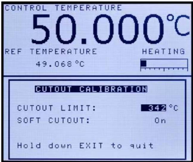
Figure 35 CUTOUT CALIBRATION menu
The Cut (CUTOUT CALIBRATION) menu is for specifying the soft cutout limit and whether or not the soft cutout is “On” or “Off”.
CUTOUT LIMIT
The CUTOUT LIMIT parameter is the cutout temperature in ^ C.
SOFT CUTOUT
The SOFT CUTOUT parameter determines if the metrology well uses the soft cutout or the hard cutout.
5.2.4.2.4 Ref
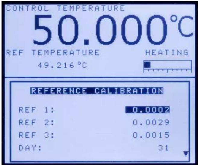
Figure 36 REFERENCE CALIBRATION menu
The Ref (REFERENCE CALIBRATION) menu contains the calibration parameters for the reference thermometer.
REF 1
The REF 1 parameter is the first calibration point for the reference resistance.
REF 2
The REF 2 parameter is the second calibration point for the reference resistance.
REF 3
The REF 3 parameter is the third calibration point for the reference resistance.
DAY
The DAY parameter is the day on which the instrument was calibrated.
MONTH
The MONTH parameter is the month in which the instrument was calibrated.
YEAR
The YEAR parameter is the year in which the instrument was calibrated.
5.2.4.3 Pass
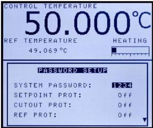
Figure 37 PASSWORD SETUP
The Pass (PASSWORD SETUP) menu is used to set the system password or enable or disable protection of certain groups of system parameters.
If a user enters the wrong password, a message will display on the screen that indicates the wrong password has been entered. The parameter window associated with that password and current menu will still display, but with view capability only. This means that any user can verify proper settings, but only users with the correct password can edit critical parameters.
SYSTEM PASSWORD
The SYSTEM PASSWORD parameter is the password used to access protected menus. The System Password is a number between one and four digits. Each digit of the password can be a number from 0 to 9. The default System Password is “1234”. If desired, the System Password can be changed in this menu by using the numeric keys to enter the new password and pressing “ENTER”.
SETPOINT PROT
The SETPOINT PROT parameter is used to enable or disable password protection for the set-point.
CUTOUT PROT
The CUTOUT PROT parameter is used to enable or disable password protection for the cutout.
REF PROT
The REF PROT parameter is used to enable or disable password protection for the reference menu.
PROG PROT
The PROG PROT parameter is used to enable or disable password protection for the program menu.
SYSTEM PROT
The SYSTEM PROT parameter is used to enable or disable password protection for the system menu.
5.2.4.4 Info (view only)
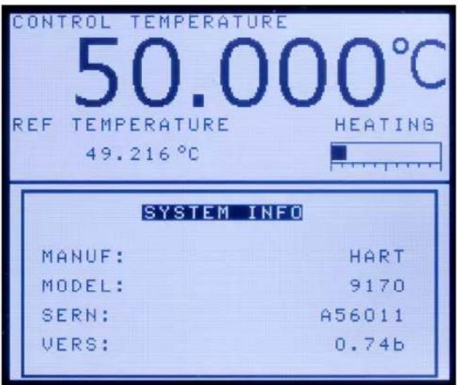
Figure 38 SYSTEM INFO menu
The Info (SYSTEM INFO) menu displays manufacturer information regarding the instrument.
MANUF
The MANUF parameter displays the name of the manufacturer.
MODEL
The MODEL parameter displays the model number of the instrument.
SERN
The SERN parameter displays the serial number of the instrument.
VERS
The VERS parameter displays the firmware version used in the instrument.
5.3 Menu Structure
| Key/Function Notes | ||
| ENTER Key | ||
| SET POINT Set the operating set-point | ||
| CONT ENABLE Enable/Disable activate heating/cooling of the instrument | ||
| SCAN RATE Set the desired scan rate | ||
| EXIT Key | ||
| CUTOUT | ||
| RESET CUTOUT Set the soft cutout | ||
| Yes, No | ||
| CUTOUT ALARM | ||
| On, Off | ||
| UP ARROW Key | ||
| DECREASE CONTRAST Display will lighten | ||
| DOWN ARROW Key | ||
| INCREASE CONTRAST Display will darken | ||
| LEFT ARROW Key | ||
| CONTROL TEMPERATURE FOCUS Only functional if Reference Probe is installed and Enabled | ||
| RIGHT ARROW Key | ||
| REFERENCE TEMPERATURE FOCUS Only functional if Reference Probe is installed and Enabled | ||
| °C / °F Key Toggle units between °C and °F | ||
| MENU Key | ||
| MAIN MENU | ||
| TEMP MENU (Temperature Menu) | ||
| SET (Control Setpoint) Main set-point menu | ||
| SETPOINT CONT ENABLE Enable/Disable activate heating/cooling of the instrument | ||
| SCAN RATE | ||
| PRESET (Select Point) | Select a preset set-point | |
| 1-8 | ||
| SETUP (Presets Setup) | Setup preset set-points | |
| SETPOINT 1-8 | ||
| CUTOUT (Cutout Settings) | Set the soft cutout | |
| CUTOUT RESET CUTOUT Yes, No CUTOUT ALARM On, Off | ||
| REF MENU (Reference Menu) | Reference probe menu | |
| SELECT PROBE SELECT Probe 1, Probe 2 ENABLE On, Off SETUP (Setup Probe) | Enable/Disable Reference Probe feature Setup reference probe1/2 | |
| SELECT Probe 1, Probe 2 | ||
Key/FunctionNotes
| TYPE | |
| ITS-90 ITS-90 coefficients | |
| SERIAL | |
| RTPW | |
| COEF A | |
| COEF B | |
| COEF C | |
| COEF A4 | |
| COEF B4 | |
| CVD Callendar Van Dusen coefficients | |
| SERIAL | |
| R0 | |
| ALPHA | |
| DELTA | |
| BETA | |
| RES Set unit to display the resistance of the reference probe | |
| SERIAL | |
| TEST (Probe Test) | |
| SELECT | |
| Probe 1, Probe 2 | |
| RESISTANCE | |
| TEMPERATURE (view only) | |
| FOCUS (Focus Select) | |
| FOCUS SELECT Select Reference/Control Focus (Control Large/Ref small or Control small/Ref large. Enabled only when reference probe option is installed and REF PROBE is ON in the ENABLE menu, otherwise FOCUS is disabled.) | |
| Control, Reference | |
| PROG MENU (Program Menu) (Ramp & Soak) allows unit to be ramped up or down automatically to a maximum or 8 different set-points | |
| SELECT (Program Select) | |
| PROGRAM | |
| 1-4 | |
| SETUP (Program Setup) | |
| PROGRAM | |
| 1-4 | |
| DIRECTION Set unit to go from set-point 1 to 8 or from 8 to 1. | |
| ↑, ↑↓ | |
| RAMP RATE Set the maximum °C/time limit | |
| SOAK MINUTES Time to control at the given set-point (minutes) | |
| CYCLES Number of times to repeat the given program | |
| POINTS Minimum # of set-points is 1 and maximum # of set-points is 8. | |
| SETPOINT 1 Setup the number of set-points defined in “POINTS” | |
| SETPOINT ? | |
| RUN (Program Run) | |
| ACTION | |
| Run, Cont, Stop | |
| PROGRAM (view only) | |
| STATUS (view only) | |
| SWITCH MENU | |
Key/FunctionNotes
| SELECT (Switch Test Select) | ||
| TEST1-4 | ||
| SETUP (Switch Test Setup) | ||
| TEST1-4 | ||
| LOW TEMPHIGH TEMPAPPROACHRAMP RATECYCLES | ||
| RUN (Switch Test Run) | ||
| ACTIONRun, StopTEST (view only)STATUS (view only) Displays TEST status of “On” or “Off” | ||
| VIEW (Switch Test Results, view only) | ||
| TESTCLOSEOPENBAND | ||
| SYSTEM MENU | ||
| SETUP MENU | DISP (Display Settings) | |
| LANGUAGEEnglish, French, ChineseDECIMALPeriod, Comma | ||
| MEAS (Measurement Settings) | ||
| STAB LIMIT (Stability Limit) Set when the unit indicates the desired stability limit has been reached. Only applies when the unit is ramping up or down and stabilizing. | ||
| STAB ALARM (Stability Alarm)On, Off | ||
| OPER (Operation Settings) | ||
| FAN LIMITAuto, Medium, Low | ||
| COMM (Communication Setup) | ||
| PORTSERIAL, ERRORSBAUD1200, 2400, 4800,9600, 19200, 38400LFOn, OffECHOOn, OffSER PER | ||
Key/FunctionNotes
| 0.5 sec, 1 sec, 2 sec,5 sec, 10 sec, 15sec, 30 sec, 1 minPRINT|On, Off | |||
| CAL MENU (Calibration Menu) | |||
| CONT (Setup Controller) Password protected menu | |||
| CUT (Cutout Calibration) Password protected menu | |||
| CUT OUT LIMITSOFT CUTOUT|On, Off | |||
6 Digital communication interface
The Metrology Well is capable of communicating with and being controlled by other equipment through the RS-232 digital interface.
With a digital interface the instrument may be connected to a computer or other equipment. This allows the user to input the set-point temperature, monitor the temperature, and access any of the other controller functions, all using remote communications equipment. The RS-232 serial interface allows serial digital communications over fairly long distances. With the serial interface, the user may access any of the functions, parameters and settings discussed in this section.
6.1 Wiring
The serial communications cable attaches to the instrument through the DB-9 connector at the back of the instrument. Figure 39, on this page shows the pin-out of this connector and suggested cable wiring. To eliminate noise, the serial cable should be shielded with low resistance between the connector (DB9) and the shield.
RS-232 Cable Wiring for IBM PC and Compatibles
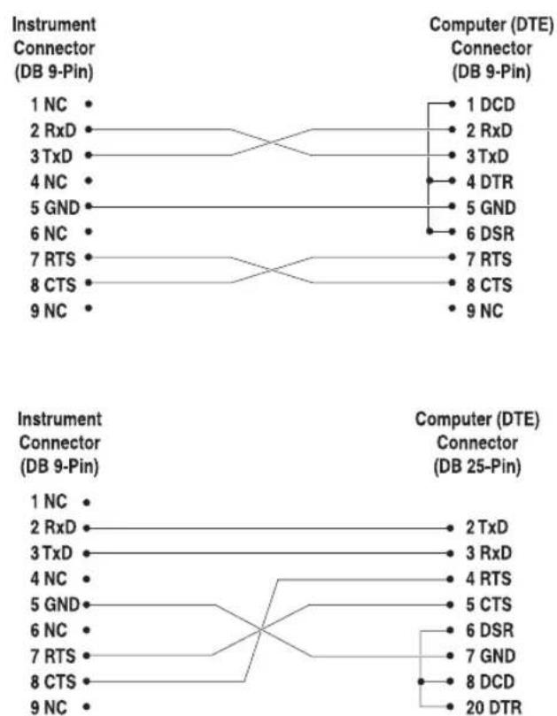
flowchart
graph LR
    subgraph Instrument Connector (DB 9-Pin)
        A1["1 NC"] --> B1["1 DCD"]
        A2["RxD"] --> B2["2 RxD"]
        A3["TxD"] --> B3["3 TxD"]
        A4["4 NC"] --> B4["4 DTR"]
        A5["GND"] --> B5["5 GND"]
        A6["6 NC"] --> B6["6 DSR"]
        A7["7 RTS"] --> B7["7 RTS"]
        A8["CTS"] --> B8["8 CTS"]
        A9["9 NC"] --> B9["9 NC"]
    end

    subgraph Computer Connector (DB 25-Pin)
        C1["1 NC"] --> D1["2 TxD"]
        C2["RxD"] --> D2["3 RxD"]
        C3["TxD"] --> D3["4 RTS"]
        C4["4 NC"] --> D4["5 CTS"]
        C5["GND"] --> D5["6 DSR"]
        C6["6 NC"] --> D6["7 GND"]
        C7["7 RTS"] --> D7["8 DCD"]
        C8["CTS"] --> D8["20 DTR"]
    end
Figure 39 RS-232 Wiring
6.1.1 Setup
Before operation the serial interface must first be set up by programming the BAUD rate and other configuration parameters. These parameters are programmed within the communications menu. The serial interface parameters can be accessed from the main menu by MENU|SYSTEM MENU|SETUP MENU|COMM. Refer to “Comm” in the Controller Operation section for more information on the serial interface parameters.
6.1.2 Serial Operation
Once the cable has been attached and the interface set up properly, the controller immediately begins transmitting temperature readings at the programmed rate. The serial communications uses 8 data bits, one stop bit, and no parity. The set-point and other commands may be sent via the serial interface to set the temperature set-point and view or program the various parameters. The interface commands are discussed in the “Digital Interface” section.
6.2 Command Syntax
Metrology Wells accept commands for setting parameters, executing functions or responding with requested data. These commands are in the form of strings of ASCII-encoded characters. As far as possible, the Metrology Well command syntax conforms to SCPI-1994. One notable exception is that compound commands are not allowed as explained below.
Commands consist of a command header and, if necessary, parameter data. All commands must be terminated with either a carriage return (ASCII 0D hex or 13 decimal) or new line character (ASCII 0A hex or 10 decimal).
Command headers consist of one or more mnemonics separated by colons (:). Mnemonics may use letter characters, the underscore character ( ), and possibly numeric digits as well. Commands are not case sensitive. Mnemonics often have alternate forms. Most mnemonics have a long form that is more readable and a short form consisting of three or four characters that is more efficient.
A mnemonic may end with a numeric suffix that specifies one of a set of independent function blocks such as input channel data paths. If a numeric suffix is omitted when a particular block must be specified, an error is generated (“Header suffix out of range”).
Query commands are commands that request data in response. Query commands have a question mark (?) immediately following the command header. Responses to query commands are generated immediately and placed in the output buffer. Responses are then transmitted automatically over the RS-232 port. Responses are lost if not read before the next command is received.
Some commands require parameter data to specify values for one or more parameters. The command header is separated from the parameter data by a space (ASCII 20 hex or 32 decimal). Multiple parameters are separated by a comma(,).
Metrology Wells do not allow compound commands (multiple commands per line separated with semicolons). All commands are sequential. The execution of each command is completed before subsequent commands are processed.
6.3 Commands by Function or Group
In this section, the commands are arranged into the following groups:
Calibration Commands - commands for Metrology Well calibration parameters.
Main Screen Commands – commands for parameters displayed on the main screen.
Program Commands – commands for program setup and status.
Reference Commands - commands for accessing reference thermometer parameters.
Setup Commands – commands for setting up communication, display, measure, and operation parameters.
Switch Commands – commands for switch testing.
System Commands - commands to report and change the status of the instrument.
Temperature Commands - commands for control temperature and cutout functions.
Table 6 Commands by function or group
| Screen Parameter | Command | Password Protection Group | Read/Write | |
| Calibration - Controller | TEMP PBAND SOUR[1]:LCON:PBAN unconditional R/W | |||
| TEMP INT SOUR[1]:LCON:INT unconditional R/W | ||||
| TEMP DER SOUR[1]:LCON:DER unconditional R/W | ||||
| GRAD PBAND SOUR2:LCON:PBAN unconditional R/W | ||||
| GRAD INT SOUR2:LCON:INT unconditional R/W | ||||
| GRAD RATIO OUTP:SLAV:RAT unconditional R/W | ||||
| Calibration - Cutout | CUTOUT LIMIT | SOUR[1]:PROT MAX | N/A | R |
| SOFT CUTOUT | SOUR[1]:PROT:SOFT | unconditional R/W | ||
| Calibration - Reference | REF 1 SENS:CAL:PAR1 | unconditional R/W | ||
| REF 2 SENS:CAL:PAR2 | unconditional R/W | |||
| REF 3 SENS:CAL:PAR3 | unconditional R/W | |||
| DAY | CAL:DATE:CAL | unconditional R/W | ||
| MONTH | CAL:DATE:CAL | unconditional R/W | ||
| YEAR | CAL:DATE:CAL | unconditional R/W | ||
| Calibration - Sensor | TEMP 1 | SOUR[1]:SENS:CAL:PAR1 | unconditional | R/W |
| TEMP 2 | SOUR[1]:SENS:CAL:PAR2 unconditional R/W | |||
| TEMP 3 | SOUR[1]:SENS:CAL:PAR3 unconditional R/W | |||
| GRAD 1 | SOUR2:SENS:CAL:PAR1 | unconditional R/W | ||
| GRAD 2 | SOUR2:SENS:CAL:PAR2 | unconditional R/W | ||
| Main Screen - Left | SETP | (see Temperature-Setup below) | N/A | R |
| CUT | (see Temperature-Cutout below) | N/A | R | |
| HEAT | OUTP[1]:DAT | N/A | R | |
| STAB | SOUR[1]:STAB:DAT | N/A | R | |
| STAB highlight | SOUR[1]:STAB:TEST | N/A | R | |
| RATE | SOUR[1]:RATE | N/A | R | |
| Main Screen - Right | RUN | (see PROGRAM ACTION below) | N/A | R |
| STEP | PROG:NUMB PPO | N/A | R | |
| SOAK | PROG:NUMB PSO | N/A | R | |
| SWIT INP:SWIT:CLOS N/A R | ||||
| TRIP INP:SWIT:TEMP N/A R | ||||
| Main Screen - Upper C/F view UNIT:TEMP none R/W | ||||
| CONTROL TEMP. | SOUR[1]:SENS:DAT [TEMP] N/A R | |||
| REF TEMP. READ, MEAS, FETC N/A R | ||||
| CUT-OUT | SOUR[1]:PROT:TRIP N/A R | |||
| Program - Run | PROGRAM ACTION | PROG:STAT | 4 | R/W |
| Program - Select | SELECT TEST | PROG:NAME | 4 | R/W |
| Program - Setup | SELECT TEST | PROG:NAME | 4 | R/W |
| DIRECTION | PROG:NUMB DIR | 4 | R/W | |
| RAMP RATE | PROG:NUMB RAMP | 4 | R/W | |
| SOAK TIME | PROG:NUMB SOAK 4 | R/W | ||
| CYCLES PROG:NUMB CYCL 4 | R/W | |||
| POINTS | PROG:NUMB POIN | 4 | R/W | |
| SETPOINT 1 | PROG:NUMB SPO1 | 4 | R/W | |
| SETPOINT 2 | PROG:NUMB SPO2 | 4 | R/W | |
| SETPOINT 3 | PROG:NUMB SPO3 | 4 | R/W | |
| SETPOINT 4 | PROG:NUMB SPO4 | 4 | R/W | |
| SETPOINT 5 | PROG:NUMB SPO5 | 4 | R/W | |
| SETPOINT 6 | PROG:NUMB SPO6 | 4 | R/W | |
| SETPOINT 7 | PROG:NUMB SPO7 | 4 | R/W | |
| SETPOINT 8 | PROG:NUMB SPO8 | 4 | R/W | |
| Reference - Select | SELECT ENABLE | CALC:CONV:SEL | 3 | R/W |
| SENS:STAT | 3 | R/W | ||
| Reference - Setup | TYPE | CALC:CONV:NAME | 3 | R/W |
| SERIAL | CALC:CONV:SNUM | 3 | R/W | |
| RTPW | CALC:CONV:PAR:VAL RTPW | 3 | R/W | |
| COEF A | CALC:CONV:PAR:VAL A | 3 | R/W | |
| COEF B | CALC:CONV:PAR:VAL B | 3 | R/W | |
| COEF C | CALC:CONV:PAR:VAL C | 3 | R/W | |
| COEF A4 | CALC:CONV:PAR:VAL A4 | 3 | R/W | |
| COEF B4 | CALC:CONV:PAR:VAL B4 | 3 | R/W | |
| R0 | CALC:CONV:PAR:VAL R0 | 3 | R/W | |
| ALPHA | CALC:CONV:PAR:VAL AL | 3 | R/W | |
| DELTA | CALC:CONV:PAR:VAL DE | 3 | R/W | |
| BETA CALC:CONV:PAR:VAL BE 3 | R/W | |||
| Reference - Test | RESISTANCE | CALC:CONV:TEST | N/A | R |
| Setup - Communication | BAUD | SYST:COMM:SER:BAUD | 5 | R/W |
| LF | SYST:COMM:SER:LIN | 5 | R/W | |
| ECHO | SYST:COMM:SER:FDUP | 5 | R/W | |
| SER PER | SYST:COMM:SER:TIME | 5 | R/W | |
| SYST:COMM:SER:FEED | 5 | R/W | ||
| PORT (ERRORS) | SYST:ERR | N/A R | ||
| Setup - Display | DECIMAL | SYST:DEC:FORM | 5 | R/W |
| LANGUAGE | DISP:LANG 5 | R/W | ||
| Setup - Measure | STAB LIMIT | SOUR[1]:STAB:LIM | 5 | R/W |
| STAB ALARM SOUR[1]:STAB:BEEP 5 R/W | ||||
| Setup - Operation FAN MODE SYST:FAN 5 R/W | ||||
| Switch - Run TEST ACTION PROG:STAT 4 R/W | ||||
| Switch - Select SELECT TEST PROG:NAME 4 R/W | ||||
| Switch - Setup SELECT TEST PROG:NAME 4 R/W | ||||
| LOW TEMP PROG:NUMB LOW 4 R/W | ||||
| HIGH TEMP | PROG:NUMB HIGH | 4 R/W | ||
| RAMP RATE | PROG:NUMB RAMP | 4 R/W | ||
| APPROACH TEMP | PROG:NUMB APPR 4 R/W | |||
| CYCLES | PROG:NUMB CYCL | 4 R/W | ||
| Switch - View | (all) PROG:DAT | N/A R | ||
| System - Information | (all) *IDN | N/A R | ||
| (none) *CLS | none | W | ||
| (none) *OPT | N/A R | |||
| (none) *STB | N/A R | |||
| (none) OUTP2:DAT | N/A R | |||
| (none) PROG:NUMB PCYC N/A R | ||||
| (none) PROG:NUMB PDIR | N/A R | |||
| (none) SENS:DAT | N/A R | |||
| (none) SYST:BEEP:IMM | N/A W | |||
| (none) SYST:PASS:CDIS | unconditional | W | ||
| (pass prompt) | SYST:PASS:CEN | unconditional | W | |
| (none) SYST:PASS:CEN:STAT | N/A R | |||
| System - Password | PASSWORD | SYST:PASS:NEW | unconditional | W |
| SETPOINT PROT | SYST:PASS:GROU1 | unconditional | R/W | |
| CUTOUT PROT | SYST:PASS:GROU2 | unconditional | R/W | |
| REF PROT | SYST:PASS:GROU3 | unconditional | R/W | |
| PROG PROT | SYST:PASS:GROU4 | unconditional | R/W | |
| SYSTEM PROT | SYST:PASS:GROU5 | unconditional | R/W | |
| Temperature - Cutout CUTOUT | SOUR[1]:PROT | 2 R/W | ||
| RESET CUTOUT | SOUR[1]:PROT:CLE | none | W | |
| CUTOUT ALARM | SOUR[1]:PROT:HIGH:BEEP | 2 R/W | ||
| Temperature - Setup | SETPOINT 1 | SOUR[1]:LIST:SPO1 | 1 | R/W |
| SETPOINT 2 | SOUR[1]:LIST:SPO2 | 1 R/W | ||
| SETPOINT 3 | SOUR[1]:LIST:SPO3 | 1 R/W | ||
| SETPOINT 4 | SOUR[1]:LIST:SPO4 | 1 R/W | ||
| SETPOINT 5 | SOUR[1]:LIST:SPO5 | 1 R/W | ||
| SETPOINT 6 | SOUR[1]:LIST:SPO6 | 1 R/W | ||
| SETPOINT 7 | SOUR[1]:LIST:SPO7 | 1 R/W | ||
| SETPOINT 8 | SOUR[1]:LIST:SPO8 | 1 R/W | ||
| SETPOINT | SOUR[1]:SPO | 1 R/W | ||
| CONT ENABLE | OUTP:STAT | 1 R/W | ||
| SCAN RATE | SOUR[1]:SLEW | 1 R/W | ||
6.4 Serial Commands - Alphabetic Listing
Each command description provides the structure (long and short format), a description of the command purpose, a command example, an example of what the command returns (as applicable to query commands), and notes specific to the command. The following apply to each group of commands:
- Numeric data, specified by the mnemonic,
, uses ASCII characters to represent numbers. Numbers may contain a plus or minus ('+' or '-'') sign, decimal point (‘.’), and exponent ('E' or 'e') with its sign. If a fractional component is received when only an integer is required, the number is rounded to the nearest integer without any resulting error message. The mnemonics DEF, MIN, and MAX are often acceptable for the default, minimum, and maximum value respectively. Unit suffixes, such as V or OHM, can be appended to numeric parameters and are accepted without error but ignored. - Unrecognized commands or commands with incorrect syntax or invalid parameters generate error messages in the error queue.
- Upper case letters designate syntax that is required when issuing the command. Lower case letters are optional and may be omitted.
• indicates a required parameter.
• [] indicates optional parameters. - () indicates a group of parameters that must be used together.
- For query commands, specifying the MIN, MAX, or DEF parameter causes the instrument to respond with the minimum, maximum, or default setting respectively.
- For set commands, specifying the MIN, MAX, or DEF parameters causes the instrument to use the minimum, maximum, or default setting respectively.
- ‘|’ indicates alternate parameter values.
•indicates a number is required. indicates numeric value is required. indicates a program number (SEQ or SWIT ) is required. indicates a Boolean value (0 or 1) is required. The mnemonics OFF and ON are also accepted for 0 and 1, respectively. indicates a conversion mnemonic is required. - indicates a parameter name is required.
indicates a serial number is required. indicates a resistance value is required.
•indicates a voltage value is required. indicates a temperature unit is required. indicates a temperature ^ C / F is required. indicates a password is required. indicates a port number is required. -
indicates a four digit number is required. -
indicates a one or two digit number is required. indicates a one or two digit number is required. indicates a one or two digit number is required. indicates a one or two digit number is required. indicates a one or two digit number is required. indicates a valid baud number is required.
\*CLS
Clear the status registers
Example: *CLS
This command has no response.
Clears all status registers(events, operations etc).
\*IDN?
Read the product information (Manufacturer, Model Number, Serial Number, and Firmware Version)
Example: *IDN?
Response: HART,9170,0,1.00
\*OPT?
Read the product configuration, reference hardware enabled (1) or not (0) (see SYST:CONF:REF)
Example: *OPT?
Response: 1
This command is a read only command and returns the state of the reference functionality (0, 1) .
CAL:DAT:CAL[?] [

NOTE: This command is unconditionally protected, which requires a password to set it.
Read or set the calibration date
Read Example: CAL:DAT:CAL?
Response: 2005,1,1
Set Example: CAL:DAT:CAL 2006,12, 30
This command reads or sets the calibration date for the unit.
CALC:CONV:NAME[?] [CVD|ITS]
![FLUKE 9172 - CALC:CONV:NAME[?] [CVD|ITS] - 1](/content/2026/05/896850/images/d00baecfcf64816da533e8eecc6a825a87f2854dd1d4acbe28b5d5b3914d19ec.jpg)
NOTE: Depending on group password setting, this command is conditionally protected.
Read or set the reference probe type
Read Example: CALC:CONV:NAME?
Response: CVD
Set Example: CALC:CONV:NAME 190
This command is password protected via group 3(Reference Protection).
CALC:CONV:PAR:CAT?
Read the list of reference probe characterization parameter names
Example: CALC:CONV:PAR:CAT?
Response: "RTPW", "A", "B", "C", "A4", "B4"
This command is a read only command, which returns the available parameters for the current probe type.
CALC:CONV:PAR:VAL[?] par[,]
![FLUKE 9172 - CALC:CONV:PAR:VAL[?] par[,] - 1](/content/2026/05/896850/images/27dac3b8a89514d06f21fb90103e07477febfbb1f67a65b9b1ac23eea5a652cb.jpg)
NOTE: Depending on group password setting, this command is conditionally protected.
Read or set a reference probe characterization parameter (A, A4, AL (Alpha), B, B4, BE (Beta), C, DE (Delta), RTPW)
Read Example: CALC:CONV:PAR:VAL? RTPW
Response: 100.000
Set Example: CALC:CONV:PAR:VAL A, 0.00385
This command is password protected via group 3 (Reference Protection).
This command returns an ITS-90 reference probe characterization parameter as desired by the user.
CALC:CONV:SEL[?] [n]
Read or set the reference probe characterization parameter set.
Read Example: CALC:CONV:SEL?
Response: 1
Set Example: CALC:CONV:SEL 1
Parameters for two probes can be stored in the instrument. This command selects the probe number.
CALC:CONV:SNUM[?] [n]
Read or set reference probe serial number.
Read Example: CALC:CONV:SNUM?
Response: 1234
Set Example: CALC:CONV:SNUM 1560D
This command allows the user to enter a reference probe serial number.
CALC:CONV:TEST[?] [n]
Test the reference probe resistance to temperature calculation
Read Example: CALC:CONV:TEST? 100.000
Response: 0.0100
This is a read only command and tests the external probe resistance.
DISP:LANG[?] [n]
Read or set the display language.
Read Example: DISP:LANG?
Response: 0
Set Example: DISP:LANG 1
This command is used to read or set the Display Language. A value of 0, 1, or 2 sets the Display Language to English, French, or Chinese respectively.
INP:SWIT:CLOS?
Read the switch input state, open (0) or closed (1)
Example: INP:SWIT:CLOS?
Response: 0
This command returns a 0 if the switch is open and a 1 if the switch is closed.
INP:SWIT:TEMP?
Read the temperature when the switch changed state.
Example: INP:SWIT:TEMP?
Response: 105.0
This command returns the temperature when the switch changed state. The units of the temperature returned is determined by the units on the display.
OUTP:SLAV:RAT[?] [n]
![FLUKE 9172 - OUTP:SLAV:RAT[?] [n] - 1](/content/2026/05/896850/images/3d5c75726532e2b3996b077f2b5e2db611b2eafdee26da67102f5f5d37fcd309.jpg)
NOTE: This command is unconditionally protected, which requires a password to set it.
Read or set the slave heater ratio
Read Example: OUTP:SLAVE:RAT?
Response: 1.0
Set Example: OUTP:SLAVE:RAT 2.0
The heater ratio is the ratio in percentage of full power between the main heaters and the bottom heaters in the hot units. For more information regarding this parameter, refer to the Controller Operation section.
OUTP[:STAT][?][0|1]
![FLUKE 9172 - OUTP[:STAT][?][0|1] - 1](/content/2026/05/896850/images/895fab5f7053a6187f5471accdbc723e243bb5e470d33ec498576ec1c109a15f.jpg)
NOTE: Depending on group password setting, this command is conditionally protected.
Read or set the heat output enable, off (0) or on (1)
Read Example: OUTP:STAT?
Response: 0
Set Example: OUTP:STAT 1
This command is password protected via group 1(Set Point protection).
This command reads the active heating or cooling output status. A “0” is returned if the output status is off, and a “1” is returned if the output status is on.
OUTP[1]:DAT?
Read the main heat output percent
Example: OUTP[1]:DAT?
Response: 18.0
This command returns the current main zone heater duty cycle.
OUTP2:DAT?
Read the gradient heat output percent
Example: OUTP2:DAT?
Response: 12.0
This command returns the current gradient zone heater duty cycle.
PROG:DAT?
Read the results of the most recent switch program execution.
Example: PROG:DAT?
Response: 80.0000, 100.0000, 20.0000
This command returns the closed, open, and band temperatures for the last switch test cycle.
PROG:NAME? []
![FLUKE 9172 - PROG:NAME? [] - 1](/content/2026/05/896850/images/271c8c00fb40e7f8fdedc918893d40f917e18b21eeeebb2801261bbc31647748.jpg)
NOTE: Depending on group password setting, this command is conditionally protected.
Read or select a program name (SEQ1, SEQ2, SEQ3, SEQ4)
Read or select a switch program name (SWIT1, SWIT2, SWIT3, SWIT4).
Read Example: PROG:NAME?
Response: SEQ1
Set Example: PROG:NAME SEQ1
This command is password protected via group 4(program protection).
Issuing program parameter SEQ1 – SEQ4 sets the sequence program. Issuing SWIT1 – SWIT4 sets the switch test program.
PROG:NUMB[?] par[,]
![FLUKE 9172 - PROG:NUMB[?] par[,] - 1](/content/2026/05/896850/images/8220a0789a629d94dd07ac8d77316d07aafcbbe183054f6e56bc15bd51b1146b.jpg)
NOTE: Depending on group password setting, this command is conditionally protected.
Read or set a program parameter (SEQ
Read or set a switch parameter (SWIT
Read Example: PROG:NUMB? SPO1
Response: 65
Set Example: PROG:NUMB HIGH,150
This command is password protected via group 4 (program protection).
In the above, example the sequence program set-point 1 is returned. If PROG:NUMB PPO? is entered, the return value is the current set-point number of the sequence program. PSO refers to the amount of time the program soaks at the given set point when stable. PCYC refers to the number of cycles the program runs. PDIR refers to the direction the program takes. A PDIR response of 0 refers to a forward path only. A response of 1 refers to a forward path and a return path. The following suffixes are read only PPO, PSO, PCYC, PDIR. The other suffixes are read and write.
PROG:STAT[?] [RUN|STOP|CONT]
![FLUKE 9172 - PROG:STAT[?] [RUN|STOP|CONT] - 1](/content/2026/05/896850/images/01805be3ffd0e8ca8799b887b76744f5babd022319c3c7389be8d9afb0a583b2.jpg)
NOTE: Depending on group password setting, this command is conditionally protected.
Read or set the selected program execution state
Read Example: PROG:STAT?
Response: 0
Set Example: PROG:STAT STOP
This command is password protected via group 4 (program protection).
If a Sequence program is not running then a value of 0 is returned otherwise a 1 is returned.
READ?, MEAS? or FETC?
Read the reference thermometer input temperature, C or F.
Example: READ?
Response: 264.262
If the external reference probe is enabled, the reference temperature is returned otherwise 0.0 is returned.
SENS:CAL:PAR[n][?][n]
![FLUKE 9172 - SENS:CAL:PAR[n][?][n] - 1](/content/2026/05/896850/images/0b4880a6ca35124dcd0b976167399e57bd8a9ce4e4a774f50a3f077ab3c9a4a6.jpg)
NOTE: This command is unconditionally protected, which requires a password to set it.
Read or set a reference input calibration parameter (:PAR1, :PAR2, :PAR3)
Read Example: SENS:CAL:PAR1?
Response: 0.2
Set Example: SENS:CAL:PAR2 0.092
Reference thermometer input commands to verify or set TEMP 1 (PAR1), TEMP 2 (PAR2), or TEMP 3 (PAR3) calibration parameters.
SENS:DAT?
Read the reference input resistance
Example: SENS:DAT?
Response: 199.9366
This command returns the resistance in ohms of the reference probe.
SENS:STAT?
Read or set the reference probe enable state off (0) or on (1).
Read Example: SENS:STAT?
Response: 1
Set Example: SENS:STAT 1
The Reference Thermometer function of the instrument can be enabled or disabled through this command.
SOUR[1]:LCON:DER[?] [n]
![FLUKE 9172 - SOUR[1]:LCON:DER[?] [n] - 1](/content/2026/05/896850/images/eac350ef45312051314aa62d0d3c37ab0cfb7dbf3b128acb898d98bcdd36acab.jpg)
NOTE: This command is unconditionally protected, which requires a password to set it.
Read or set the main control loop derivative time, seconds
Read Example: SOUR1:LCON:DER?
Response: 1.5
Set Example: SOUR1:LCON:DER 5
The main zone derivative is the derivative time in seconds that the unit's PID controller used for main zone control.
SOUR[1]:LCON:INT[?] [n]
![FLUKE 9172 - SOUR[1]:LCON:INT[?] [n] - 1](/content/2026/05/896850/images/a7911042100b8e9594ed98d296d87ebcb99dde6020f1038b5bf61405dee6c285.jpg)
NOTE: This command is unconditionally protected, which requires a password to set it.
Read or set the main control loop integral time, seconds
Read Example: SOUR1:LCON:INT?
Response: 20.0
Set Example: SOUR1:LCON:INT 10
The main zone integral is the integration time in seconds that the unit's PID controller uses for main zone control.
SOUR[1]:LCON:PBAN[?] [n]
![FLUKE 9172 - SOUR[1]:LCON:PBAN[?] [n] - 1](/content/2026/05/896850/images/48f67543033144951cf8b335272ef102ad1450fcc21a8bd1267c7aa7b7bba0fe.jpg)
NOTE: This command is unconditionally protected and requires a password to set it.
Read or set the main control loop proportional band, ^ C
Read Example: SOUR1:LCON:PBAN?
Response: 1.5
Set Example: SOUR1:LCON:PBAN 7
The main zone proportional band is the gain in ^ that the unit's proportional-integral-derivative (PID) controller uses for main zone control.
SOUR[1]:LIST:SPO[i][?][n]
![FLUKE 9172 - SOUR[1]:LIST:SPO[i][?][n] - 1](/content/2026/05/896850/images/92da41643032c5eb8bb3c23635f635bc4513515b2d6c2dc393ae87909d3a9130.jpg)
NOTE: Depending on group password setting, this command is conditionally protected.
Read or set a main temperature preset set-point
Read Example: SOUR1:LIST:SPO6?
Response: 25.00
Set Example: SOUR1:LIST:SPO6 100.00
This command is password protected via group 1(Set Point protection).
This sets the preset set-points found in Temp Menu under Setup.
SOUR[1]:PROT[?] [n]
![FLUKE 9172 - SOUR[1]:PROT[?] [n] - 1](/content/2026/05/896850/images/e56f6a5011c0d0fe24fe2196baa733709dc023c8844d42f51f35cbfafb50d9a8.jpg)
NOTE: Depending on group password setting, this command is conditionally protected.
This command is password protected via group 2(Cutout Protection).
Read or set the temperature cutout set-point in C or F
Read Example: SOUR:PROT?
Response: 140
Set Example: SOUR:PROT 140.00
Returns the current value of the cutout set-point.
SOUR[1]:PROT? MAX
Read or set the temperature cutout limit
Read Example: SOUR:PROT? MAX
Response: 200
Set Example: SOUR:PROT 200
Returns the maximum calibrated cutout temperature.
SOUR[1]:PROT:CLE
Reset the temperature cutout
Example: SOUR:PROT:CLE
This command has no response.
If the Metrology Well exceeds the temperature set in the soft cutout menu (or when using the command SOUR:PROT) or if it exceeds the maximum operating temperature of the instrument, a cutout condition occurs. If this happens, the unit enters cutout mode and will not actively heat or cool until the user issues this command to clear the cutout.
SOUR[1]:PROT:HIGH:BEEP[?] [n]
Reads or sets the cutout alarm.
Read Example: SOUR:PROT:HIGH:BEEP?
Response: 0
Set Example: SOUR:PROT:HIGH:BEEP 1
This command enables or disables the Cutout Alarm. 0 disables the Alarm and 1 enables the Alarm.
SOUR[1]:PROT:SOFT[?] [0|1]
Read or set the soft cut-out enable, off (0) or on (1)
Read Example: SOUR:PROT:SOFT?
Response: 1
Set Example: SOUR:PROT:SOFT 0
If this command is issued, as in the above set example, the hard cutout limit is used, otherwise the soft cutout is used.
SOUR[1]:PROT:TRIP?
Read the temperature cutout tripped state
Example: SOUR:PROT:TRIP?
Response: 0
A value of 0 is returned if the cutout set point has not been reached. Otherwise a value of 1 is returned and the cutout set point has been reached.
SOUR[1]:RATE?
Read the control temperature rate of change, ^ C or ^ F per minute
Example: SOUR:RATE?
Response: 0.531
The response to this command starts out high initially and decreases as the set point is reached.
SOUR:SENS:CAL:PAR[n][?][n]
![FLUKE 9172 - SOUR:SENS:CAL:PAR[n][?][n] - 1](/content/2026/05/896850/images/d8e2727e09715faf97bd228d082fe18acb9917ccecda94d779f9605e4b4ff4de.jpg)
NOTE: This command is unconditionally protected and requires a password to set it.
Read or set a control temperature calibration parameter (:PAR1, :PAR2, :PAR3)
Read Example: SOUR:SENS:CAL:PAR1?
Response: 0.0
Set Example: SOUR:SENS:CAL:PAR2 0.02
This command reads or sets the calibration parameters for main control. See the “Calibration of your Metrology Well” section for more detail.
SOUR[1]:SENS:DAT? [TEMP]
Read the control temperature, ^ C or ^ F
Example: SOUR:SENS:DAT?
Response: 30.285°C (current control temp)
The current control temperature is returned if the above example is used or if TEMP is appended to the end of the example.
SOUR[1]:SENS:DAT? [RES]
Read the control sensor resistance
Example: SOUR:SENS:DAT? RES
Response: 111.28
When RES is appended to the end of the example above, the internal sensor resistance is returned.
SOUR[1]:SLEW[?] [n]
![FLUKE 9172 - SOUR[1]:SLEW[?] [n] - 1](/content/2026/05/896850/images/f51b16232398e20be2699ef8864202d279a8fc82113c1343203fbaa6c877f68d.jpg)
NOTE: Depending on group password setting, this command is conditionally protected.
Read or set the control set-point slew rate, ^ C/F per minute
Read Example: SOUR:SLEW?
Response: 500
Set Example: SOUR:SLEW 100
This command is password protected via group 1(Set Point protection).
This command sets the controller ramp rate ( ^ C/F per min).
SOUR[1]:SPO[?] [n]
![FLUKE 9172 - SOUR[1]:SPO[?] [n] - 1](/content/2026/05/896850/images/f7a559ada43bbeeef8840dc4c43d394eb0cc8e3a04d23e7b681c4d10fc0ed7df.jpg)
NOTE: Depending on group password setting, this command is conditionally protected.
Read or set the control set-point, ^ C or ^ F
Read Example: SOUR:SPO?
Response: 50.000
Set Example: SOUR:SPO 100.00
This command is password protected via group 1(Set Point protection).
This command returns the value of the control set point based on the system temperature unit.
SOUR[1]:STAB:BEEP[?] [0|1]
![FLUKE 9172 - SOUR[1]:STAB:BEEP[?] [0|1] - 1](/content/2026/05/896850/images/2e1730ebefb65e12fc6903dafd047cc918942c733b57dcfdd116040b2f2e17d3.jpg)
NOTE: Depending on group password setting, this command is conditionally protected.
Read or set the stability alert enable
Read Example: SOUR:STAB:BEEP?
Response: 1
Set Example: SOUR:STAB:BEEP 0
Enable or disable the audible stability alert.
SOUR[1]:STAB:DAT?
Read the control temperature stability, ^ C or ^ F
Example: SOUR:STAB:DAT?
Response: 0.306
The controller stability is returned.
SOUR[1]:STAB:LIM[?] [n]
![FLUKE 9172 - SOUR[1]:STAB:LIM[?] [n] - 1](/content/2026/05/896850/images/c1c2d5e770f822147c46b7b15bd6ea26e0aed64dd79d7a9430e0d58288e2d7cd.jpg)
NOTE: Depending on group password setting, this command is conditionally protected.
Read or set the control temperature stability limit, ^ C or ^ F
Read Example: SOUR:STAB:LIM?
Response: 0.005
Set Example: SOUR:STAB:LIM .005
This command is password protected via group 5(System protection).
SOUR[1]:STAB:TEST?
Read the temperature stability status
Example: SOUR:STAB:TEST?
Response: 0
A value of 0 is returned if the controller is not stable at the current set point.
Otherwise a value of 1 is returned if the controller is stable at the current set point.
SOUR2:LCON:INT[?] [n]
![FLUKE 9172 - SOUR2:LCON:INT[?] [n] - 1](/content/2026/05/896850/images/48cbb6429996f30b717ae5e34241d6e047e71013262f4841229897d346914ac7.jpg)
NOTE: This command is unconditionally protected and requires a password to set it.
Read or set the gradient temperature control loop integral time, seconds
Read Example: SOUR2:LCON:INT?
Response: 40.0
Set Example: SOUR2:LCON:INT 20
The gradient integral is the integration time in seconds that the unit's PID controller uses for gradient control.
SOUR2:LCON:PBAN[?] [n]
![FLUKE 9172 - SOUR2:LCON:PBAN[?] [n] - 1](/content/2026/05/896850/images/ccdc247d824e43d4706d148f54d7163d8e8b1c9cfca6eac076226308abc7f8fb.jpg)
NOTE: This command is unconditionally protected and requires a password to set it.
Read or set the gradient temperature control loop proportional band, ^ C
Read Example: SOUR2:LCON:PBAN?
Response: 5.0
Set Example: SOUR2:LCON:PBAN 10
The gradient proportional band is the gain in ^ that the unit's PID controller uses for gradient control.
SOUR2:SENS:CAL:PAR[n][?][n]
![FLUKE 9172 - SOUR2:SENS:CAL:PAR[n][?][n] - 1](/content/2026/05/896850/images/597079657f873104e772af7f918a13a29ce6a52f8c82b175273fcdf7e44bf4ab.jpg)
NOTE: This command is unconditionally protected, which requires a password to set it.
Read or set a gradient temperature calibration parameter (:PAR1, :PAR2)
Read Example: SOUR2:SENS:CAL:PAR1?
Response: 0.0
Set Example: SOUR2:SENS:CAL:PAR1 5.0
Parameter 1 is the offset in °C for the axial gradient at the 1st gradient calibration point (GRAD 1).
Parameter 2 is the offset in °C for the axial gradient at the 2nd gradient calibration point (GRAD 2)
SYST:BEEP:IMM
Beep the system beeper
Example: SYST:BEEP:IMM
The system beeper should make an audible sound in response to this command.
SYST:COMM:SER:BAUD[?] []
Read or set serial interface baud rate
Read Example: SYST:COMM:SER:BAUD?
Response: 2400
Set Example: SYST:COMM:SER:BAUD 9600
SYST:COMM:SER:FDUP[?] [0|1]
Read or set serial interface echo enable, on (1) or off (0)
Read Example: SYST:COMM:SER:FDUP?
Response: 0
Set Example: SYST:COMM:SER:FDUP 1
This command enables or disables echo.
SYST:COMM:SER:FEED[?] [0|1]
Read or set serial interface auto-printing enable, on (1) or off (0)
Read Example: SYST:COMM:SER:FEED?
Response: 1
Set Example: SYST:COMM:SER:FEED 0
This command enables or disables auto printing to the serial port.
SYST:COMM:SER:LIN[?] [0|1]
Read or set serial interface linefeed enable, on (1) or off (0)
Read Example: SYST:COMM:SER:LIN?
Response: 0
Set Example: SYST:COMM:SER:LIN 1
This command enables or disables line feed.
SYST:COMM:SER:TIM[?] [n]
Read or set serial interface auto-printing interval
Read Example: SYST:COMM:SER:TIM?
Response: 3
Set Example: SYST:COMM:SER:TIM 5
This command sets the interval to print to the serial port.
SYST:DEC:FORM[?] [0|1]
Read or set the decimal format (period (0), comma (1))
Read Example: SYST:DEC:FORM?
Response: 0
Set Example: SYST:DEC:FORM 1
A response of 0 implies that a period will be used for a decimal. Otherwise, a comma will be used as the decimal.
SYST:ERR?
Read the errors from the error queue
Example: SYST:ERR?
Response: command protected
This command response reports the errors in the error queue.
SYST:FAN? [n]
Read or set the system fan mode.
Example: SYST:FAN?
Response: 2
Set Example: SYST:FAN 1
The system fan has three operating modes: Auto (2), Medium (1), low (0).
SYST:PASS:CDIS
Disable access to password protected setting commands
Example: SYST:PASS:CDIS
This command has no response.
This command disables the system password protection.
SYST:PASS:CEN [n]
Enable access to password protected setting commands
Example: SYST:PASS:CEN 1234
This command has no response.
This command enables the system password. This password needs to be enabled in order to use the group conditionally protected commands. When the power of the instrument is cycled, system password protection is disabled.
SYST:PASS:CEN:STAT?
Read the access state of password protected setting commands
Example: SYST:PASS:CEN:STAT?
Response: 0
This command reports the current status of the system password.
SYST:PASS:GROU[n][?][0|1]
NOTE: This command is unconditionally protected, which requires a password to set it.
Read or set a command group protection (off (0), on (1), n=1, 2, 3, 4 or 5)
Read Example: SYST:PASS:GROU1?
Response: 0
Set Example: SYST:PASS:GROU2 1
This command enables and disables group protection passwords.
Group 1: Set point protection
Group 2: Cutout protection
Group 3: Reference Protection
Group 4: Program Protection
Group 5: System Protection
SYST:PASS:NEW |DEF
NOTE: This command is unconditionally protected, which requires a password to set it.
Set the password
Example: SYST:PASS:NEW 1234
This command has no response.
This command allows the user to set the system password.
UNIT:TEMP[?][C|F]
Read or set the temperature unit
Read Example: UNIT:TEMP?
Response: C
Set Example: UNIT:TEMP F
Depending on unit setting, a C or F is returned with the above read example.
6.5 Non-SCPI Process Commands
This section contains Non-SCPI commands. These are available for users that require Non-SCPI commands for their application. These commands are used differently from the SCPI commands discussed in the previous section, the command protocol and response is different. These commands do not require a question mark (?) for a query, and respond to a query by first outputting the command and colon before the
data. These commands are not password protected. The associated SCPI command is referenced where appropriate.
6.6 Non-SCPI Command by Function or Group
| SCREENPARAMETER COMMAND | PASSWORDPROTECTION READ/WRITE | |||
| Setup - Communication DU | PLEX du None R/W | |||
| LINEFEED If None | R/W | |||
| SAMPLE RATE sa | None R/W | |||
| Temperature Settings HIGH | LIMIT hl None R | |||
| SET POINT s None | R/W | |||
| TEMPERATURE | t | None R | ||
| System Information | VERSION | *ver | None | R |
| System Setup | °C/°F | u None R/W | ||
\*ver
Read the Model number and Main code version (Model Number, Firmware version). A question mark (?) is not required to query this command.
Example: *ver
ver. 9171, 1.00
du
Read or set serial interface echo enable, on (1) or off (0).
"On" is Full Duplex and "Off" is Half duplex. The response will be the command string followed by Full or Half. Refer to SYST:COMM:SER:FDUP
Read Example: du
du: HALF
Set Example: du 1
This command enables or disables the echo.
hl
Read the maximum temperature setting for the unit. This command is query only and responds with the command string and a Colon followed by the maximum temperature and associated units.
Read Example: hl
hl: 660.00 C
lf [n]
Read or set the serial interface linefeed enable, where “n” is a value 1 or 0. [0] = LF OFF, [1] = LF ON. The default setting is Off. (Off and on may be used in place of 0 and 1 respectively). If “n” is left blank, the command will be treated as a query. This query responds with the command string and a Colon followed by the LF setting.
Refer to SYST:COMM:SER:LIN
Read Example: If
lf: OFF
Set Example: If on
s [n]
Read or Set the temperature control set-point in °C or °F (based on current system units). Where “n” is a real value with acceptance limits based on the model. If “n” is left blank, the command will be treated as a query. This query responds with the command string “set:” followed by the temperature setting and associated units. Refer to SOUR[1]:SPO command
Read Example: s
set: 100.00 C
Set Example: s 250
sa [n]
Read or Set the serial interface auto printing interval. Where “n” is an integer value from 0-60. If “n” is 0, the auto print will be disabled. Values range from 1 to 60 and are in seconds. If “n” is left blank, the command will be treated as a query. This query responds with the command string “sa” and a Colon followed by the interval setting. Refer to SYST:COMM:SER:TIME command
Read Example: sa
sa: 5
Set Example: s 10
t
Read the control temperature in ^ C or ^ F (based on current system units). This command is query only and responds with the command string and a Colon followed by the temperature and associated units. Refer to SOUR[1]:SENS:DAT command
Read Example: t
t: 99.988 C
u[n]
Read or Set the display temperature units, where "n" is a character "C" of "F".
Default: C If “n” is left blank, the command will be treated as a query. This query responds with the command string “u” and a Colon followed by the unit setting. Refer to UNIT:TEMP command
Read Example: u
u: C
Set Example: u F
7 Calibration of your Metrology Well
7.1 General

NOTE: For assistance with the process or any questions regarding the calibration of the Metrology Well, contact an Authorized Service Center.
7.2 Terminology
If the External Reference option was purchased, the Metrology Well actually consists of two separate instruments combined. When calibrating the Metrology Well, two separate calibrations will be conducted. For convenience in terminology, the External Reference is referred to as the Readout. The dry-block calibrator is referred to as the Heat Source. The Readout and Heat Source combine make up the Metrology Well.
The Axial Uniformity is referred to as the Vertical Gradient.
Resistance Certification is the process utilized to take As Found or As Left Data. The process does not change any calibration parameters. The process records the state of the instrument prior to adjusting the calibration parameters, As Found Data; or it verifies the state of the instrument after adjusting the calibration parameters, As Left Data.

NOTE: The Measuring and Test Equipment (M&TE) is referred to as the Unit Under Test (UUT).
7.3 Fundamentals
It is assumed that the technician is familiar with the Metrology Well Technical Guide.
It is assumed that the calibration will only be performed by trained personnel.
Readout calibration or Heat Source calibration may be optional depending on UUT configuration and customer requirement.
Environmental Conditions
Temperature range: 23^ ± 4^
Ambient relative humidity: below 60%

NOTE: Do not use an aluminum insert in the hot Metrology Wells (9172 or 9173). In the 9172, the insert will become stuck. In the 9173, there is a potential to melt the insert. Inserts purchased from Fluke are engraved with the corresponding model.
Calibration Equipment
Table 7 Test equipment specifications
| CLASSIFICATION MINIMUM USE SPECIFICATIONS | |
| Test Insert (Sleeve) | Two 1⁄4" holes, one 40 mm shorter (Fluke Model Numbers 9170-INST, 9171-INST, 9172-INST, or 9173-INST) |
| Primary Reference | |
| Readout 20 ppm | |
| Probe 0.008°C @ 0°C | |
| Secondary Reference | |
| Readout 20 ppm | |
| Probe 0.008°C @ 0°C | |
| External Reference | |
| Shorting wire (0Ω) | See Table 8, Standard resistor specifications, on this page |
| Four-Wire Resistors See Table 8, Standard resistor specifications, on this page | |
Table 8 Standard resistor specifications
| U_s1 (k=1) U | s2 (k=1) U | T(k=2) | |||
| Resistance (Ω) | Reference Resistor Uncertainty (ppm) | Reference Resistor Uncertainty (Ω) | TCR Uncertainty (ppm) | TCR Uncertainty (Ω) | Total Uncertainty (Ω) |
| 0 — 0.000040 — — 0.00008 | |||||
| 25 | 1.8 | 0.000045 | 0.3 | 0.0000075 | 0.00009 |
| 100 | 2.00 | 0.00020 | 0.3 | 0.00003 | 0.00041 |
| 200 | 2.65 | 0.00053 | 0.3 | 0.00006 | 0.0011 |
| 400 | 2.65 | 0.00106 | 0.3 | 0.00012 | 0.0022 |
917xMetrologyWellCalibrationProcess ReadoutCalibration
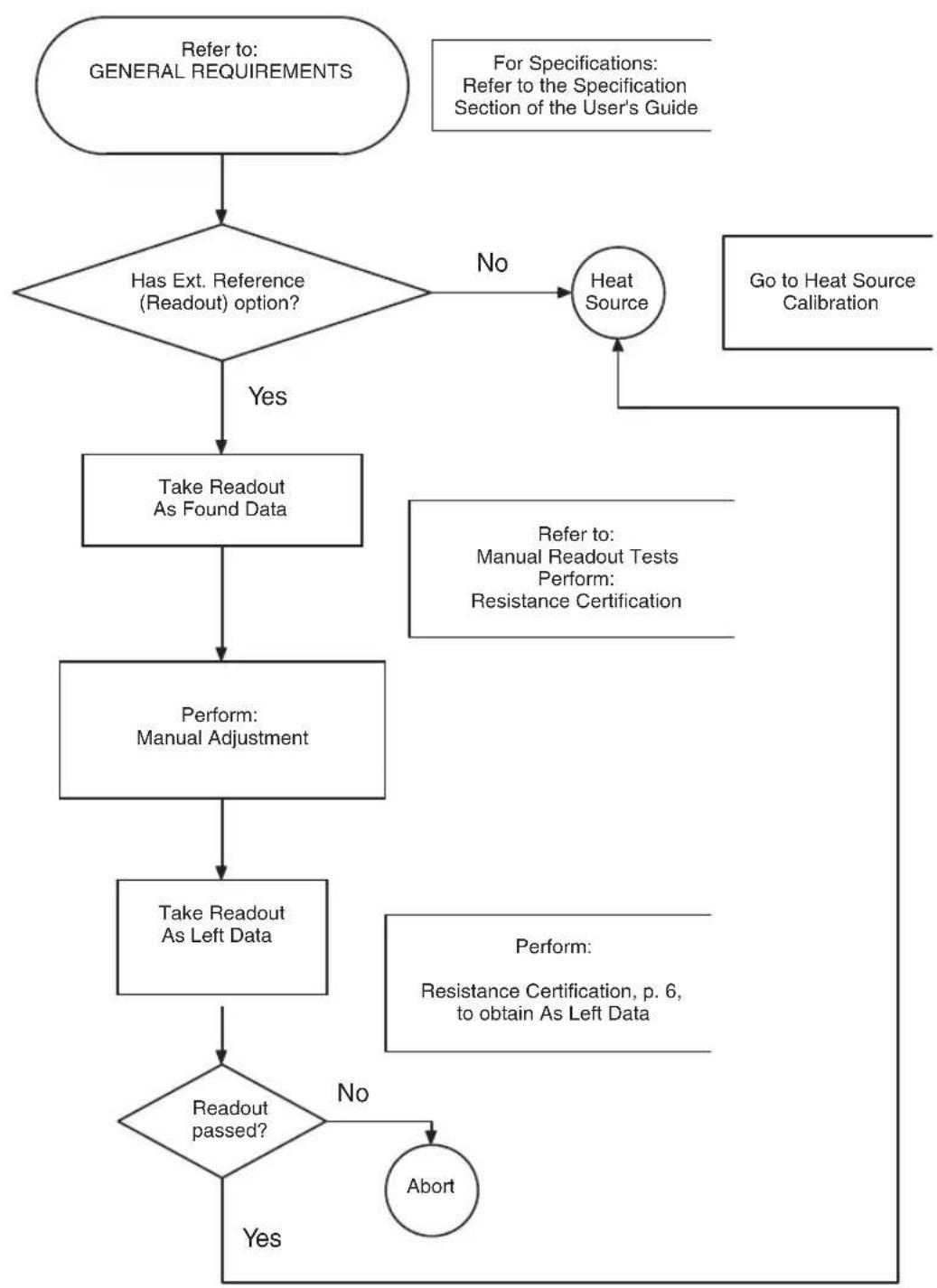
flowchart
graph TD
    A["Refer to: GENERAL REQUIREMENTS"] --> B{Has Ext. Reference (Readout) option?}
    B -->|Yes| C["Take Readout As Found Data"]
    B -->|No| D["Heat Source"]
    D --> E["Go to Heat Source Calibration"]
    C --> F["Perform: Manual Adjustment"]
    F --> G["Take Readout As Left Data"]
    G --> H{Readout passed?}
    H -->|No| I["Abort"]
    H -->|Yes| J["End"]
    I --> D
    style A fill:#f9f,stroke:#333
    style D fill:#ccf,stroke:#333
Figure 40 Flow chart for readout calibration
917x Metrology Well Calibration Process HeatSourceCalibration
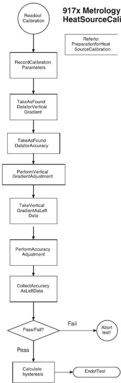
flowchart
graph TD
    A["Readout Calibration"] --> B["RecordCalibration Parameters"]
    B --> C["TakeAsFound DataforVertical Gradient"]
    C --> D["TakeAsFound DataforAccuracy"]
    D --> E["PerformVertical GradientAdjustment"]
    E --> F["TakeVertical GradientAsLeft Data"]
    F --> G["PerformAccuracy Adjustment"]
    G --> H["CollectAccuracy AsLeftData"]
    H --> I{Pass/Fail?}
    I -->|Fail| J["Abort test!"]
    I -->|Pass| K["Calculate hysteresis"]
    J --> L["EndofTest"]
    K --> L
Figure 41 Flow Chart for heat source calibration
7.4 Procedure
7.4.1 Manual readout tests

NOTE: Collect As Left data after Adjustment using Table 9, One-year accuracy specifications, on this page, limits of error.

NOTE: Repeat the same steps below for each resistance. Collect the data and make the adjustments in the order listed.
1. Resistance certification
a. Connect the correct standard resistor, calibrated to the uncertainty required for the UUT, to the input. (See Table 8, Standard resistor specifications, on page 94.)
b. Collect no less than 40 and no more than 400 readings and compute the average. Ensure the average is within the one-year accuracy limits specified in Table 9.
Table 9 One-year accuracy specifications
| Resistance One-Year Accuracy |
| 0Ω±0.0005Ω |
| 25Ω±0.000625Ω |
| 100Ω±0.0025Ω |
| 200Ω±0.005Ω |
| 400Ω±0.01Ω |
c. Compute the standard deviation of the measurements and see that they are not greater than the limits given in Table 10. If they are, repeat the measurements or have the instrument serviced.
Table 10 Limits of standard deviation of measurement
| Resistance | Standard Deviation (1σ) of Measurement |
| 0Ω | 0.0003 |
| 25Ω | 0.0004 |
| 100Ω | 0.0015 |
| 200Ω | 0.002 |
| 400Ω | 0.004 |
2. Manual Adjustment

NOTE: Repeat the same steps for each resistance. Do the adjustments in the order listed.
Table 11 Required order for adjustment parameter
| Adjustment Parameter Resistance | |
| REF1 | 0Ω |
| REF2 | 100Ω |
| REF3 | 400Ω |

NOTE: Access to the calibration parameters needs to be enabled using the Serial Command SYST:PASS:CEN followed by a space and the correct password.

NOTE: Calibration requires adjustment of the REF1, REF2, and REF3 parameters at 0, 100 and 400Ω respectively. The order in which the adjustments are performed is important. The adjustment of the REF3 parameter must be performed last as the adjustments of REF1 and REF2 affect the measurement at 400Ω but REF3 does not affect the measurements at 0 or 100Ω. Refer to Table.
a. As noted above the order in which the adjustments are performed is critical.
b. The calibration parameters are accessed from the front panel by selecting MENU|SYSTEM|CAL MENU. Enter the correct password to access the parameters. The parameters may also be accessed through the RS232 interface using the commands shown in Table 12.
Table 12 Serial command, adjustment parameters
| Command Adjustment Parameter |
| SENS:CAL:PAR1REF1 |
| SENS:CAL:PAR2REF2 |
| SENS:CAL:PAR3REF3 |
c. During the adjustment, collect no less than 40 and no more than 400 readings and compute the average.
d. Connect the 0 resistor to the input and measure its resistance. Note the difference between 0 and the measured resistance. The new REF 1 is given by subtracting the difference from the current REF 1. Adjust REF 1 as needed.
e. Repeat for the other resistors as noted in Table 11.
f. Verify the accuracy by performing Manual Resistance Certification, using Table 9, One-year accuracy specifications, on page 97, limits of error.
7.4.2 Manual heat source calibration
1. Preparation for heat source calibration
a. Fan speed
i. In order to perform the calibration properly, the “Fan Limit” MUST be set to “Auto.”
ii. If the “Fan Limit” is not set to “Auto”, the instrument may not meet all of its specifications.
b. Test sleeves
i. Use a test sleeve with two 1/4 inch holes. Ensure the test sleeve is appropriate for the specific model being calibrated.
ii. Ensure that one of the 1/4 inch holes is 40mm shorter than the other.
c. Well insulator (9170 and 9171 only)
i. In order to perform the calibration properly, the well insulator MUST be installed.
ii. If the well insulator is not installed, the instrument may not meet all of its specifications.
2. Heat source - manual as found data testing process

NOTE: Record all calibration parameters prior to starting As Found testing.
a. Vertical gradient (axial uniformity)
i. Ensure that the test sleeve has two 14 " wells. One of the wells needs to have a 40mm plug in it or needs to be drilled 40mm shorter than the other well.
ii. Place a PRT in each well.
iii. The reference temperature PRT goes in the deeper of the two wells.
iv. The differential temperature PRT goes in the shallower of the two wells giving an axial displacement of 40mm from the bottom.
v. Set the unit to the first set-point (Low temperature set-point) as indicated in Table.
vi. Allow the unit to stabilize (about 30 min).
vii. Take the average difference between the two PRT ( T ) for 2
minutes.
viii. Record the average.
ix. Repeat Steps v - viii for the second set-point (High temperature set-point)
Table 13 Axial gradient as found/as left specifications
| Model Set-point (°C) | Soak (min) | Spec ( ± ^ ) | 2 Spec | |
| 9170 | -35 30 0.0 | 20 0.005 | ||
| 140 | ||||
| 9171 | -30 30 0.0 | 20 0.005 | ||
| 155 0.030 | ||||
| 9172 | 100 30 0.0 | 25 0.005 | ||
| 425 0.100 | 0.010 | |||
| 9173 | 100 30 0.0 | 50 0.005 | ||
| 660 0.200 | 0.030 |
b. Accuracy test
i. Set the temperature set-point to first/next set-point. See Table 14, Heat source as found data/as left data specifications, on this page for temperatures per model.
ii. Allow the UUT to reach the set-point temperature.
iii. Allow settling time.
iv. Read and record the temperature displayed on the read-out using the calibration reference probe.
v. Repeat steps i to iv for the other required temperatures listed in Table 14, Heat source as found data/as left data specifications, on this page for the appropriate model.
vi. Calculate the error and record.
Table 14 Heat source as found data/as left data specifications
| Model | Set-Point | Soak Time | Spec ( ± °C) | Guard Band (%) | 2 Spec (°C) | |
| 9170(Descending Order) | -45 | 30 min | 0.100 | 100 | 60 | 0.008 |
| -35 | ||||||
| 0 | ||||||
| 50 | ||||||
| 100 | ||||||
| 140 | ||||||
| Model Set-Point Soak | Time Spec ( ± ^ ) | Guard Band | (%) 2 Spec ( ^ ) | |||
| 9171(Descending Order) | -30 30 m | in 0.100 100 60 | 0.008 | |||
| 0 | ||||||
| 50 | ||||||
| 100 | ||||||
| 155 | ||||||
| 9172(Ascending Order) | 100 30 m | in 0.100 100 60 | 0.008 | |||
| 150 0.150 | 0.010 | |||||
| 250 0.150 | 0.012 | |||||
| 350 0.200 | 0.014 | |||||
| 425 0.200 | 0.016 | |||||
| 9173(Ascending Order) | 100 30 m | in 0.200 100 60 | 0.008 | |||
| 200 0.200 | 0.012 | |||||
| 350 0.200 | 0.016 | |||||
| 500 0.250 | 0.020 | |||||
| 660 0.250 | 0.030 | |||||
3. Heat source manual adjustment and as left data
a. Axial (vertical) gradient adjustment (alignment)
i. Ensure that the test sleeve has two 14 " wells. One of the wells needs to have a 40mm plug in it or needs to be drilled 40mm shorter than the other well. Ensure the test sleeve is specific to the model being calibrated.
ii. Place a PRT in each well.
iii. One PRT for the reference temperature PRT goes in the deeper of the two wells.
iv. One PRT for the differential temperature PRT goes in the shallower of the two wells giving an axial displacement of 40mm from the bottom.
v. Set the unit to the first set-point (Low temperature set-point) as indicated in Table 13, Axial gradient as found/as left specifications, on opposite page.
vi. Allow the unit to stabilize (approximately 30 min).
vii. Take the average difference between the two PRTs ( T ) for 2 minutes.
viii. Store the “New Gradient Value” using serial command SOUR2:SENS:CAL:PAR1
Where,
New Gradient Value = Previous Gradient Value - (T_40mm - T_Ref)
ix. Perform this operation three (3) times, 15 minutes apart. Allow 2 minutes soak time at each temperature.
x. Update "New Gradient Value" at each iteration.
xi. T should be within 5 mK by the 3rd iteration
xii. If not, retest and review or abort test
xiii. Repeat Steps v -xii at the second set-point (High temperature set-point) as indicated in Table 13, Axial gradient as found/as left specifications, on page 100.
xiv. Store the “New Gradient Value” using the serial command SOUR2:SENS:CAL:PAR2.
b. Heat source manual axial gradient (vertical uniformity) as left data
i. Ensure that the test sleeve has two 14 " wells. One of the wells needs to have a 40mm plug in it or needs to be drilled 40mm shorter than the other well. Ensure the test sleeve is specific to the model being calibrated.
ii. Place a PRT in each well.
iii. One PRT for the reference temperature PRT goes in the deeper of the two wells.
iv. One PRT for the differential temperature PRT goes in the shallower of the two wells giving an axial displacement of 40mm from the bottom.
v. Set the unit to the first set-point (Low temperature set-point) as indicated in Table 15.
vi. Allow the unit to stabilize (about 30 min).
vii. Take the average difference between the two PRT ( T ) for 2 minutes.
viii. Record data.
ix. Repeat steps v–viii at the second set-point (High temperature set-point) as indicated in Table 15.
x. Record data.
xi. Determine pass/fail according to specifications in Table 15.
Table 15 As left axial alignment specs
| Model | Set-point (°C) | Soak (after adj) (min) | Tolerance Spec ( ± °C) | 2 Spec |
| 9170–3530 | 0.0200.005 | |||
| 140 | ||||
| Model | Set-point (°C) | Soak (after adj) (min) | Tolerance Spec ( ± ^ ) | 20 Spec |
| 9171–3030 | 0.0200.005 | |||
| 1550.030 | ||||
| 917210030 | 0.0250.005 | 010 | ||
| 4250.1000 | ||||
| 917310030 | 0.0500.005 | 030 | ||
| 6600.2000 |
4. Heat source manual accuracy adjustment
a. Set the instrument to the first set-point.
b. Allow the instrument to stabilize (about 30 min.)
c. Record temperature and stability data.
d. Repeat steps a–c for each set-point.
e. Determine if stability is acceptable at each set-point (refer to Table 14, Heat source as found data/as left data specifications, on page 100).
f. Calculate temperature bias offset at each set-point and update parameters (refer to Table 16, Heat source accuracy adjustment specifications, on this page).

NOTE: To calculate the bias offset, simply subtract the reference temperature from the set-point and enter the difference, i.e. set-point = 30^ , actual temperature = 30.6^ .
$$ T _ {R E F} - T _ {S P T} = O f f s e t $$
Thus, 30^ - 30.6^ = -0.6^ offset
Table 16 Heat source accuracy adjustment specifications
| Model | Nominal Align Set-point (°C) Parameter | Offset Spec | ||
| Nominal | Tolerance (±) | |||
| 9170 | -35SOUR1:SENS:CAL:PAR10.0002.500 | |||
| 0SOUR1:SENS:CAL:PAR2 | ||||
| 140 | SOUR1:SENS:CAL:PAR3 | |||
| 9171 | -30SOUR1:SENS:CAL:PAR10.0002.500 | |||
| 0SOUR1:SENS:CAL:PAR2 | ||||
| 155 | SOUR1:SENS:CAL:PAR3 | |||
| 9172 | 100SOUR1:SENS:CAL:PAR10.000 | 10.000 | ||
| 250SOUR1:SENS:CAL:PAR2 | ||||
| 425SOUR1:SENS:CAL:PAR3 | ||||
| 9173 | 100SOUR1:SENS:CAL:PAR10.00010.000 | |||
| 350SOUR1:SENS:CAL:PAR2 | ||||
| 660SOUR1:SENS:CAL:PAR3 | ||||
- Heat source manual accuracy as left data
a. Set the instrument to the first set-point.
b. Allow the instrument to stabilize (about 30 min).
c. Record temperature and stability data.
d. Repeat steps a–c for each set-point in ascending and descending order.
e. Determine if stability is acceptable at each set-point (refer to Table 13, Axial gradient as found/as left specifications, on page 100).
f. Determine if the accuracy is acceptable at each set-point (refer to Table 13, Axial gradient as found/as left specifications, on page 100).
7.4.3 Hysteresis
- Determine the difference between the ascending and descending mid-point data.
- Determine pass/fail against hysteresis specification listed in Table 2, Metrology Well Specifications, on page 9.
8 Maintenance
The Metrology Well has been designed with the utmost care. Ease of operation and simplicity of maintenance have been a central theme in the product development. With proper care, the instrument should require very little maintenance. Avoid operating the instrument in an oily, wet, dirty, or dusty environment. Operating the instrument in a draft-free environment facilitates improved performance of the instrument.
- If the outside of the instrument becomes soiled, it may be wiped clean with a damp cloth and mild detergent. Do not use harsh chemicals on the surface which may damage the paint or plastic.
- It is important to keep the well of the calibrator clean and clear of any foreign matter. DO NOT use fluid to clean out the well.
- The instrument should be handled with care. Avoid knocking or dropping the calibrator.
- The removable sleeves can become covered with dust and carbon material. If the buildup becomes too thick, it could cause the sleeves to become jammed in the wells. Avoid this build up by periodically buffing the sleeves clean.
- If a sleeve should be dropped, examine the sleeve for deformities before inserting it in the well. If there is any chance of jamming the sleeve in the well, file or grind off the protuberance.
- DO NOT allow the probe stems to drop into the well or harshly impact the well bottom. This type of action can cause a shock to the sensor.
- If a hazardous material is spilled on or inside the instrument, the user is responsible for taking the appropriate decontamination steps as outlined by the national safety council with respect to the material.
- If the mains supply cord becomes damaged, replace it with a cord of the appropriate gauge wire for the current of the instrument. If there are any questions, contact an Authorized Service Center for more information.
- Before using any cleaning or decontamination method, other than those recommended by Fluke, users should check with an Authorized Service Center to insure the proposed method will not damage the equipment.
- If the instrument is used in a manner not in accordance with the equipment design, the operation of the instrument may be impaired or safety hazards may arise.
- The over-temperature cutout should be checked every 6 months to see that it is working properly. In order to check the user selected cutout, follow the controller directions for setting the cutout. Set the instrument temperature higher than the cutout. Check to see if the display shows cutout and the temperature is decreasing.
8.1 Regular metrology well performance analysis
For optimum performance and lowest possible uncertainty budgets, use the guidelines set forth below.
Accuracy drift
The display temperature of the Metrology Well will drift over time. This is due to a variety of factors affecting the temperature control PRT. Any PRT is subject to changes depending on how it is used and the environment it is used in. This is no different for any PRT in a calibration application. In addition, manufacturing variables in the sensing element itself can result in greater or lesser impact from use and environment. Oxidation and contamination from the sensor's environment will create changes requiring new calibration constants depending on the temperature range and normal operation of the instrument. Oxidation and contamination are generally not factors when Metrology Wells are used exclusively below 200°C. Oxidation can form in the body of the PRT platinum sensor wire in the range of 300°C to 500°C. Contamination is primarily a problem following prolonged use above 500°C. Additionally, vibration from handling or transportation will strain the delicate PRT element, changing its resistance. Some of this strain may come out by annealing at a slightly higher temperature than the instrument is typically used at. It is recommended to avoid unnecessary temperature cycling. Cycling the temperature up and down between minimum and maximum temperatures excessively may also cause strain on the PRT element.
Effects from control sensor drift may be avoided by using an external temperature reference. In the case that the calibration of the display value is required, a program of monitoring and recalibration must be implemented, just as with any calibration standard. Regularly check the accuracy of the Metrology Well with an adequate temperature reference and keep records as a part of your instrument maintenance routine. When the accuracy drifts to a point where it is no longer acceptable, then have the instrument recalibrated. Your records will provide data for determining a calibration interval appropriate for your history of use and accuracy requirements.
Stability
The stability specification of the Metrology Well was determined under laboratory conditions of steady ambient temperature and air flow. While this instrument has been designed to minimize ambient effects, they will still have some effect. For the best results, avoid quickly-changing ambient temperatures and drafty conditions.
Axial Uniformity
Metrology well axial uniformity should be checked periodically. Use the process outlined in EA 10/13 or a similar process. If, due to a drift in the differential thermocouples, the axial uniformity has changed outside the limits set by the user's uncertainty budget, adjust the axial gradient as outlined in the Metrology Well Calibration section of this guide and recalibrate the Metrology Well.
9 Troubleshooting
This section contains information on troubleshooting.
In the event that the Metrology Well appears to function abnormally, this section may help to find and solve the problem. Several possible problem conditions are described along with likely causes and solutions. If a problem arises, please read this section carefully and attempt to understand and solve the problem. If the Metrology Well seems faulty or the problem cannot otherwise be solved, contact an Authorized Service Center for assistance. Be sure to have the instrument model number, serial number, and voltage available.
9.1 Troubleshooting
| Problem Causes and Solutions | |
| The display is blank Check the fuses. If a fuse blows, it may be due to a power surge or a component failure. Replace the fuse once. DO NOT replace the fuse with one of a higher current rating. Always replace the fuse with one of the same rating, voltage, and type. If the fuse blows a second time, it is likely caused by failure of a component part.Power Cord. Check that the power cord is plugged in and connected to the instrument.AC Mains Power. Insure the circuit supplying power to the instrument is on. | |
| The instrument heats slowly | Scan/Scan Rate. Check the Scan and Scan Rate settings. The Scan may be on with the Scan Rate set low. |
| If the display shows an abnormal temperature | The sensor is disconnected, open or shorted. Please contact a Service Center for further instructions. |
| If the display shows cutout | Cutout. The software cutout is set too low. Check and adjust the cutout setting by pressing “Exit” from the main screen. |
| Temperature readout is not the actual temperature of the well OR Incorrect temperature reading | Noise. With the instrument stable, slowly rotate the entire instrument. If no change occurs, the instrument may need to be calibrated. Contact an Authorized Service Center for calibration service. If the display changes more than twice the normal display deviation, another unit in the area could be emitting RF energy. Move the instrument to a different location and rotate it again. If the temperature is correct in this new area or deviates differently than the first area, RF energy is present in the room. If you have to perform the test in the effected area, use the comparison test to eliminate any possible errors.Operating Parameters. Insure that all operating parameters for the Metrology Well, reference thermometer, and/or probe parameters match the Report of Calibration that was sent with the instrument and/or probe. |


- Limited Warranty & Limitation of Liability
- Table of Contents
- Before You Start ....1
- Specifications and Environmental Conditions .....9
- Quick start ....13
- Parts and controls ....19
- Controller operation....27
- Digital communication interface....67
- Calibration of your Metrology Well 93
- Maintenance ....105
- Troubleshooting ....107
- Figures
- Tables
- Before You Start
- Introduction
- Symbols Used
- Safety Information
- Warnings
- GENERAL
- BURN HAZARD
- ELECTRICAL HAZARD
- Cautions
- CE Comments
- EMC Directive
- Immunity Testing
- Emission Testing
- Low Voltage Directive (Safety)
- Authorized Service Centers
- Fluke Corporation
- Fluke Int'l Corporation
- Fluke South East Asia Pte Ltd.
- Specifications and Environmental Conditions
- Specifications
- Environmental Conditions
- Quick start
- Unpacking
- 9170
- 9171
- 9172
- 9173
- Setup
- System Setup
- Display
- Language
- Decimal
- Measure
- Stability Limit
- Example:
- Stability Alarm (STAB ALARM)
- Setting the Temperature
- Set-point Setup
- Reference Probe (-R models only)
- Probe Connection
- Measure Temperature
- Parts and controls
- Back panel
- Power Cord Plug (1)
- Power Switch (2)
- Serial Connector (3)
- Fan (4)
- Front panel
- Display (1)
- Soft Keys (2)
- Buttons (3)
- Reference Thermometer Connection (-R models only) (4)
- Switch Connectors (5)
- Block Temperature Indicator (U.S. Patent 7,561,058) (6)
- Front Panel Display
- Control Focus
- Reference Focus (-R models only)
- Heating/Cooling Status
- Soft Key Functions
- Editing Windows
- Front Panel Buttons
- Numeric Keys (3)
- ENTER (7)
- Menu (8)
- EXIT (9)
- °C/°F (10)
- Up/Down (△▽) Arrows (11)
- Left/Right (◀ ▷) Arrows (11)
- Accessories
- Controller operation
- Main Screen
- CONTROL TEMPERATURE
- REF TEMPERATURE
- HEATING, COOLING, CUTOUT
- CONTROL - SETP (Set-point)
- CONTROL - CUT (Cutout)
- CONTROL - HEAT/COOL
- CONTROL - STAB (Stability)
- CONTROL - RATE
- PROGRAM - RUN
- PROGRAM - STEP
- PROGRAM - SOAK
- PROGRAM - SWIT (Switch)
- PROGRAM - TRIP
- SWITCH - TEST
- SWITCH - CYCL (Cycle)
- SWITCH - CLOS (Close)
- SWITCH - OPEN
- Main Menu
- Temp Menu
- Set
- SETPOINT
- CONT ENABLE
- SCAN RATE
- Preset
- Setup
- Cutout
- CUTOUT
- RESET CUTOUT
- CUTOUT ALARM
- Ref Menu (-R instruments only)
- Select
- PROBE SELECT
- ENABLE
- Setup
- SELECT
- TYPE (ITS-90)
- TYPE (CVD)
- TYPE (Res)
- Test
- RESISTANCE
- TEMPERATURE (view only)
- Focus (-R instruments only)
- FOCUS SELECT
- Prog Menu
- Select
- Setup
- PROGRAM
- DIRECTION
- RAMP RATE
- SOAK MINUTES
- CYCLES
- POINTS
- Run
- ACTION
- PROGRAM (view only)
- STATUS (view only)
- Switch Menu
- Select
- Setup
- TEST
- LOW TEMP
- HIGH TEMP
- APPROACH
- Run
- TEST (view only)
- View (view only)
- CLOSE
- OPEN
- BAND
- Switch wiring and example
- System Menu
- Setup menu
- Disp
- Meas
- STAB LIMIT
- STAB ALARM
- Oper
- Comm
- PORT
- BAUD
- LF
- ECHO
- SER PER
- Cal Menu
- Cont
- TEMP PBAND
- TEMP INT
- TEMP DER
- GRAD PBAND
- GRAD INT
- Sensor
- TEMP 1
- TEMP 2
- TEMP 3
- GRAD 1
- GRAD 2
- DAY
- MONTH
- YEAR
- Cut
- CUTOUT LIMIT
- SOFT CUTOUT
- Ref
- REF 1
- REF 2
- REF 3
- Pass
- SYSTEM PASSWORD
- SETPOINT PROT
- CUTOUT PROT
- REF PROT
- PROG PROT
- SYSTEM PROT
- Info (view only)
- MANUF
- MODEL
- SERN
- VERS
- Menu Structure
- Digital communication interface
- Wiring
- Setup
- Serial Operation
- Command Syntax
- Commands by Function or Group
- Serial Commands - Alphabetic Listing
- \*CLS
- \*IDN?
- \*OPT?
- CALC:CONV:NAME[?] [CVD|ITS]
- CALC:CONV:PAR:CAT?
- CALC:CONV:PAR:VAL[?] par[,]
- CALC:CONV:SEL[?] [n]
- CALC:CONV:SNUM[?] [n]
- CALC:CONV:TEST[?] [n]
- DISP:LANG[?] [n]
- INP:SWIT:CLOS?
- INP:SWIT:TEMP?
- OUTP:SLAV:RAT[?] [n]
- OUTP[:STAT][?][0|1]
- OUTP[1]:DAT?
- OUTP2:DAT?
- PROG:DAT?
- PROG:NAME? []
- PROG:NUMB[?] par[,]
- PROG:STAT[?] [RUN|STOP|CONT]
- READ?, MEAS? or FETC?
- SENS:CAL:PAR[n][?][n]
- SENS:DAT?
- SENS:STAT?
- SOUR[1]:LCON:DER[?] [n]
- SOUR[1]:LCON:INT[?] [n]
- SOUR[1]:LCON:PBAN[?] [n]
- SOUR[1]:LIST:SPO[i][?][n]
- SOUR[1]:PROT[?] [n]
- SOUR[1]:PROT? MAX
- SOUR[1]:PROT:CLE
- SOUR[1]:PROT:HIGH:BEEP[?] [n]
- SOUR[1]:PROT:SOFT[?] [0|1]
- SOUR[1]:PROT:TRIP?
- SOUR[1]:RATE?
- SOUR:SENS:CAL:PAR[n][?][n]
- SOUR[1]:SENS:DAT? [TEMP]
- SOUR[1]:SENS:DAT? [RES]
- SOUR[1]:SLEW[?] [n]
- SOUR[1]:SPO[?] [n]
- SOUR[1]:STAB:BEEP[?] [0|1]
- SOUR[1]:STAB:DAT?
- SOUR[1]:STAB:LIM[?] [n]
- SOUR[1]:STAB:TEST?
- SOUR2:LCON:INT[?] [n]
- SOUR2:LCON:PBAN[?] [n]
- SOUR2:SENS:CAL:PAR[n][?][n]
- SYST:BEEP:IMM
- SYST:COMM:SER:BAUD[?] []
- SYST:COMM:SER:FDUP[?] [0|1]
- SYST:COMM:SER:FEED[?] [0|1]
- SYST:COMM:SER:LIN[?] [0|1]
- SYST:COMM:SER:TIM[?] [n]
- SYST:DEC:FORM[?] [0|1]
- SYST:ERR?
- SYST:FAN? [n]
- SYST:PASS:CDIS
- SYST:PASS:CEN [n]
- SYST:PASS:CEN:STAT?
- SYST:PASS:GROU[n][?][0|1]
- SYST:PASS:NEW |DEF
- UNIT:TEMP[?][C|F]
- Non-SCPI Process Commands
- Non-SCPI Command by Function or Group
- \*ver
- du
- hl
- lf [n]
- s [n]
- sa [n]
- t
- u[n]
- Calibration of your Metrology Well
- General
- Terminology
- Fundamentals
- Environmental Conditions
- Calibration Equipment
- 917xMetrologyWellCalibrationProcess ReadoutCalibration
- Procedure
- Manual readout tests
- Resistance certification
- Manual Adjustment
- Manual heat source calibration
- Preparation for heat source calibration
- Heat source - manual as found data testing process
- NOTE: Record all calibration parameters prior to starting As Found testing.
- b. Accuracy test
- Heat source manual adjustment and as left data
- Heat source manual accuracy adjustment
- Hysteresis
- Maintenance
- Regular metrology well performance analysis
- Accuracy drift
- Stability
- Axial Uniformity
- Troubleshooting
- Troubleshooting
Brand : FLUKE
Model : 9172
Category : Temperature regulator