
1620A DewK - Temperature regulator FLUKE - Free user manual and instructions
Find the device manual for free 1620A DewK FLUKE in PDF.


| Product Type | Precision Temperature and Humidity Regulator |
| Brand | Fluke |
| Model | 1620A DewK |
| Temperature Measurement Range | -200°C to 2315°C (depending on probe) |
| Temperature Accuracy | ±0.1°C (typical) |
| Humidity Measurement Range | 0% to 100% RH |
| Humidity Accuracy | ±2% RH (typical) |
| Input Types | Thermocouple (J, K, T, E, R, S) and RTD (Pt100) |
| Display | High-resolution LCD with backlight |
| Data Logging | Internal memory up to 100,000 readings |
| Communication | USB and RS-232 interfaces |
| Power Supply | 100-240 VAC, 50/60 Hz or 9V battery |
| Dimensions | 200 x 100 x 50 mm |
| Weight | 0.5 kg |
| Main Functions | Temperature/humidity measurement, data logging, alarms, calibration |
| Maintenance | Clean with dry cloth; periodic calibration recommended |
| Safety Approvals | CE, EMC compliant |
| Spare Parts | Thermocouple probes, battery, AC adapter |
| Repairability | Authorized Fluke service centers |
| General | RoHS compliant, rugged design |
Frequently Asked Questions - 1620A DewK FLUKE
User questions about 1620A DewK FLUKE
0 question about this device. Answer the ones you know or ask your own.
Ask a new question about this device
Download the instructions for your Temperature regulator in PDF format for free! Find your manual 1620A DewK - FLUKE and take your electronic device back in hand. On this page are published all the documents necessary for the use of your device. 1620A DewK by FLUKE.
USER MANUAL 1620A DewK FLUKE
Thermo-Hygrometer User'sGuide
Limited Warranty & Limitation of Liability
Each product from Fluke Corporation, Hart Scientific Division ("Hart") is warranted to be free from defects in material and workmanship under normal use and service. The warranty period is one year for the Thermo-Hygrometer. The warranty period begins on the date of the shipment. Parts, product repairs, and services are warranted for 90 days. The warranty extends only to the original buyer or end-user customer of a Hart authorized reseller, and does not apply to fuses, disposable batteries or to any other product, which in Hart's opinion, has been misused, altered, neglected, or damaged by accident or abnormal conditions of operation or handling. Hart warrants that software will operate substantially in accordance with its functional specifications for 90 days and that it has been properly recorded on non-defective media. Hart does not warrant that software will be error free or operate without interruption. Hart does not warrant calibrations on the Thermo-Hygrometer.
Hart authorized resellers shall extend this warranty on new and unused products to end-user customers only but have no authority to extend a greater or different warranty on behalf of Hart. Warranty support is available if product is purchased through a Hart authorized sales outlet or Buyer has paid the applicable international price. Hart reserves the right to invoice Buyer for importation costs of repairs/replacement parts when product purchased in one country is submitted for repair in another country.
Hart's warranty obligation is limited, at Hart's option, to refund of the purchase price, free of charge repair, or replacement of a defective product which is returned to a Hart authorized service center within the warranty period.
To obtain warranty service, contact your nearest Hart authorized service center or send the product, with a description of the difficulty, postage, and insurance prepaid (FOB Destination), to the nearest Hart authorized service center. Hart assumes no risk for damage in transit. Following warranty repair, the product will be returned to Buyer, transportation prepaid (FOB Destination). If Hart determines that the failure was caused by misuse, alteration, accident or abnormal condition or operation or handling, Hart will provide an estimate or repair costs and obtain authorization before commencing the work. Following repair, the product will be returned to the Buyer transportation prepaid and the Buyer will be billed for the repair and return transportation charges (FOB Shipping Point).
THIS WARRANTY IS BUYER'S SOLE AND EXCLUSIVE REMEDY AND IS IN LIEU OF ALL OTHER WARRANTIES, EXPRESS OR IMPLIED, INCLUDING BUT NOT LIMITED TO ANY IMPLIED WARRANTY OF MERCHANTABILITY OR FITNESS FOR A PARTICULAR PURPOSE. HART SHALL NOT BE LIABLE FOR ANY SPECIAL, INDIRECT, INCIDENTAL. OR CONSEQUENTIAL DAMAGES OR LOSSES, INCLUDING LOSS OF DATA, WHETHER ARISING FROM BREACH OF WARRANTY OR BASED ON CONTRACT, TORT, RELIANCE OR ANY OTHER THEORY.
Since some countries or states do not allow limitation of the term of an implied warranty, or exclusion or limitation of incidental or consequential damages, the limitations and exclusions of this warranty may not apply to every buyer. If any provision of this Warranty is held invalid or unenforceable by a court of competent jurisdiction, such holding will not affect the validity or enforceability of any other provision.
Fluke Corporation, Hart Scientific Division
799 E. Utah Valley Drive • American Fork, UT 84003-9775 • USA
Phone: +1.801.763.1600 • Telefax: +1.801.763.1010
E-mail: support@hartscientific.com
www.hartscientific.com
Subject to change without notice. • Copyright © 2006 • Printed in USA
Table of Contents
1 Before You Start . . . . . . . . . . . . . . . . . . . . . . . . . . . . . . . . . . . . . 1
1.1 Symbols Used....1
1.2 Safety Information....2
1.2.1 Warnings 2
1.2.2 Cautions 3
1.3 Authorized Service Centers. 3
2 Introduction 7
3 Specifications and Environmental Conditions ..... 9
3.1 Specifications....9
3.2 Environmental Conditions.... 10
4 Quick Start 11
4.1 Unpacking.... 11
4.2 Use Proper Care . . . . . . . . . . . . . . . . . . . . . . . . . . . . . . . . . . . . . . . . . . . 11
4.3 Learn About the Features and Components ..... 11
4.4 Install the Battery 11
4.5 Connect the Sensor 12
4.6 Connect the Power Source ..... 12
4.7 Switch the Power On 12
4.8 Measure Temperature ..... 12
5 Parts and Controls ..... 13
5.1 Front Panel 13
5.2 Top Panel ..... 14
5.3 Right Side Panel.... 14
5.4 Left Side Panel 15
5.5 Back Panel....16
5.6 Quick Buttons 17
5.7 Configurations....17
5.8 Accessories ..... 18
6 General Operation....19
6.1 DC Power Source 19
6.2 Battery....19
6.3 Sensor Configuration ..... 20
6.4 Power Switch ..... 20
6.5 Power On Self-Test ..... 20
6.6 Display Contrast. 20
6.7 Display 21
6.8 Alarm Screen 21
6.9 Measuring ..... 21
6.10 Unit of Temperature ..... 21
6.11 Recording Measurements ..... 21
6.12 Sensors ..... 21
6.12.1 Sensor Accuracy 22
7 Menu Functions. 25
7.1 Channel Menu....26
7.1.1 Channel Setting 26
7.1.2 Sensor ID 27
7.1.3 Sensor Lock....28
7.1.4 Sensor Cal. 29
7.2 Display Menu 31
7.2.1 Display Setting 31
7.2.2 Display Layout 32
7.2.3 Field Data 34
7.2.4 Graph Scale 36
7.2.5 Display Reset 38
7.3 Data Menu. 38
7.3.1 Data Record....39
7.3.1.1 Record Setting 40
7.3.1.2 Data View 42
7.3.1.3 Data Print 43
7.3.1.4 Data Storage 44
7.3.1.5 Data Clear 45
7.3.2 Daily Stats. 46
7.3.2.1 Stats Setting....47
7.3.2.2 Stats View 48
7.3.2.3 Stats Print 49
7.3.2.4 Stats Reset 49
7.3.2.5 Stats Clear 50
7.4 Alarm Menu....51
7.4.1 Alarm Setting 51
7.4.2 Sensor Alarm 52
7.4.3 System Alarm....53
7.4.4 Alarm View 54
7.5 System Menu ..... 55
7.5.1 System Setting 56
7.5.2 Date Time 57
7.5.3 Comm Setting....59
7.5.3.1 Serial 60
7.5.3.2 RF (optional) 62
7.5.3.3 LAN....63
7.5.4 Password 65
7.5.5 System Info 67
8 Digital Communications Interface ..... 69
8.1 Overview....69
8.1.1 Serial RS-232 69
8.1.2 RF Wireless (optional) 70
8.1.3 LAN....70
8.1.4 Command Syntax 70
8.2 Commands 71
8.2.1 Alarm Commands....80
8.2.1.1 ALARm:BATTery? 80
8.2.1.2 ALARm:BATTery:ENABLE? 80
8.2.1.3 ALARm:BATTery:ENABLE
8.2.1.4 ALARm:BEEP:ENABLE?.....80
8.2.1.5 ALARm:BEEP:ENABLE
8.2.1.6 ALARm:CLEar....81
8.2.1.7 ALARm:DATE:FIRST? 81
8.2.1.8 ALARm:DATE:LAST? 81
8.2.1.9 ALARm:DISPLAY:ENABLE? 81
8.2.1.10 ALARm:DISPLAY:ENABLE
8.2.1.11 ALARm:PORT? 82
8.2.1.12 ALARm:PORT
8.2.1.13 ALARm:PORT:ENABLE?.....82
8.2.1.14 ALARm:PORT:ENABLE
8.2.1.15 ALARm:POWer? 82
8.2.1.16 ALARm:POWer:ENABLE? 82
8.2.1.17 ALARm:POWer:ENABLE
8.2.1.18 ALARm:RHUMidity
8.2.1.19 ALARm:RHUMidity
8.2.1.20 ALARm:RHUMidity
8.2.1.21 ALARm:RHUMidity
8.2.1.22 ALARm:RHUMidity
8.2.1.23 ALARm:RHUMidity
8.2.1.24 ALARm:RHUMidity
8.2.1.25 ALARm:RHUMidity
8.2.1.26 ALARm:RHUMidity
8.2.1.27 ALARm:RHUMidity
8.2.1.28 ALARm:RHUMidity
8.2.1.29 ALARm:RHUMidity
8.2.1.30 ALARm:RHUMidity
8.2.1.31 ALARm:RHUMidity
8.2.1.32 ALARm:RHUMidity
8.2.1.33 ALARm:RHUMidity
8.2.1.34 ALARm:RHUMidity
8.2.1.35 ALARm:RHUMidity
8.2.1.36 ALARm:TEMPurature
8.2.1.37 ALARm:TEMPurature
8.2.1.38 ALARm:TEMPurature
8.2.1.39 ALARm:TEMPurature
8.2.1.40 ALARm:TEMPurature
8.2.1.41 ALARm:TEMPurature
8.2.1.42 ALARm:TEMPurature
8.2.1.43 ALARm:TEMPurature
8.2.1.44 ALARm:TEMPurature
8.2.1.45 ALARm:TEMPurature
8.2.1.46 ALARm:TEMPurature
8.2.1.47 ALARm:TEMPurature
8.2.1.48 ALARm:TEMPurature
8.2.1.49 ALARm:TEMPurature
8.2.1.50 ALARm:TEMPurature
8.2.1.51 ALARm:TEMPurature
8.2.1.52 ALARm:TEMPurature
8.2.1.53 ALARm:TEMPurature
8.2.1.54 ALARm:TIME:FIRST? 91
8.2.1.55 ALARm:TIME:LAST? 91
8.2.2 Measurement Commands ..... 92
8.2.2.1 CALCulate:AVERage:CLEar. 92
8.2.2.2 CALCulate
8.2.2.3 CALCulate
8.2.2.4 CALCulate
8.2.2.5 CALCulate[
8.2.2.6 CALCulate[
8.2.2.7 CALCulate[
8.2.2.8 CALCulate
8.2.2.9 CALCulate[
8.2.2.10 CALCulate[
8.2.2.11 CALCulate[
8.2.2.12 CALCulate[
8.2.2.13 FETCh? [
8.2.2.14 FORMAT:TDST:STATe? 95
8.2.2.15 FORMAT:TDST:STATc
8.2.2.16 MEASure? [
8.2.2.17 READ? [
8.2.3 Data Commands. 96
8.2.3.1 DATa:DSTatistics:ENABLE? 96
8.2.3.2 DATa:DSStatistics:ENABLE
8.2.3.3 DATa:DSTatistics:HOUR? [MINIMAX|DEF] 97
8.2.3.4 DATa:DSTatistics:HOUR
8.2.3.5 DATa:DSStatistics:RENable? 97
8.2.3.6 DATa:DSTatistics:RENable
8.2.3.7 DATa:DSStatistics:RHOur? [MIN|MAX|DEF] 97
8.2.3.8 DATa:DSStatistics:RHOur
8.2.3.9 DATa:DSTatistics:RECORD:BTIMe? [
8.2.3.10 DATa:DSTatistics:RE Cord:CLEar 98
8.2.3.11 DATa:DSTatistics:RE Cord:COUNt? [
8.2.3.12 DATa:DSTatistics:RECORD:DATE? [
8.2.3.13 DATa:DSTatistics:RECORD:ETIME? [
8.2.3.14 DATa:DSTatistics:RE Cord:FIND? (
8.2.3.15 DATa:DSTatistics:RE Cord:VALuc?
8.2.3.16 DATa:RE Cord:CLEar. 99
8.2.3.17 DATa:RECORD:FEED:RHUMidity
8.2.3.18 DATa:RE Cord:FEED:RHUMidity
8.2.3.19 DATa:RECORD:FEED:TEMPerature
8.2.3.20 DATa:RECORD:FEED:TEMPerature
8.2.3.21 DATa:RE Cord:FREE? 100
8.2.3.22 DATa:RE Cord:OPEN? 101
8.2.3.23 DATa:RECORD:OPEN [(
ond>)[,
8.2.3.24 DATa:RE Cord:READ? [
8.2.3.25 DATa:RE Cord:TIME? [MIN|MAX|DEF]. 102
8.2.3.26 DATa:RE Cord:TIME
8.2.4 Measurement Control Commands....102
8.2.4.1 INITiate 102
8.2.4.2 INITiate:CONTinuous? 102
8.2.4.3 SENSOR: AVERAGE? 102
8.2.4.4 SENSor:AVERAGE
8.2.4.5 SENSOR
8.2.4.6 SENSor
8.2.4.7 SENSor
8.2.4.8 SENSOR
8.2.4.9 SENSo
8.2.4.10 TRIGger:TIMer? [MIN|MAX|DEF] 104
8.2.4.11 TRIGger:TIMer
8.2.5 Channel Commands ..... 105
8.2.5.1 ROUTe:CLOSE?
8.2.5.2 ROUTe:CLOSE
8.2.5.3 ROUTe:OPEN?
8.2.5.4 ROUTe:OPEN
8.2.6 Calibration Commands ..... 105
8.2.6.1 CALibrate
8.2.6.2 CALibrate
8.2.6.3 CALibrate
8.2.6.4 CALibrate
8.2.6.5 CALibrate
8.2.6.6 CALibrate
8.2.6.7 CALibrate
8.2.6.8 CALibrate
8.2.6.9 CALibrate
8.2.6.10 CALibrate
8.2.6.11 CALibrate
8.2.7 System Commands 108
8.2.7.1 *IDN? 108
8.2.7.2 *OPT? 108
8.2.7.3 *RST....108
8.2.7.4 SYSTem:BEEP 109
8.2.7.5 SYSTem:BOOT:VERSION? 109
8.2.7.6 SYSTem:ERRor? 109
8.2.7.7 SYSTem:CODE:VERSION?.....109
8.2.7.8 SYSTem:VERSION?.....109
8.2.7.9 UNIT:TEMPerature? 109
8.2.7.10 UNIT:TEMPerature
8.2.8 Communication Interface Commands....110
8.2.8.1 SYSTem:COMMunicate:RADio:CHANnel?....110
8.2.8.2 SYSTem:COMMunicate:RADio:CHANnel
8.2.8.3 SYSTem:COMMunicate:RADio:ENABLE?....110
8.2.8.4 SYSTem:COMMunicate:RADio:ENABLE
8.2.8.5 SYSTem:COMMunicate:RADio:INSTRument?....110
8.2.8.6 SYSTem:COMMunicate:RADio:INSTRument
8.2.8.7 SYSTem:COMMunicate:RADio:MODem?.....110
8.2.8.8 SYSTEM:COMMunicate:RADio:MODem
8.2.8.9 SYSTem:COMMunicate:RADio:OPTION?....111
8.2.8.10 SYSTEM:COMMunicate:RADio:PAN?....111
8.2.8.11 SYSTem:COMMunicate:RADio:PAN
8.2.8.12 SYSTem:COMMunicate:RADio:SIGNal?.....111
8.2.8.13 SYSTem:COMMunicate:RADio:SNUMber?.....111
8.2.8.14 SYSTem:COMMunicate:SERial:BAUD? [MIN|MAX|DEF]. . . . . . . . . . . . . . . 111
8.2.8.15 SYSTem:COMMunicate:SERial:BAUD
8.2.8.16 SYSTEM:COMMunicate:SERial:FDUPlex? 111
8.2.8.17 SYSTem:COMMunicate:SERial:FDUPlex
8.2.8.18 SYSTem:COMMunicate:SERial:FEED? 112
8.2.8.19 SYSTem:COMMunicate:SERial:FEED
8.2.8.20 SYSTem:COMMunicate:SERial:LINefeed?....112
8.2.8.21 SYSTem:COMMunicate:SERial:LINefeed
8.2.8.22 SYSTem:COMMunicate:SERial:TIME? [MIN|MAX|DEF] ..... 112
8.2.8.23 SYSTem:COMMunicate:SERial:TIMe
8.2.8.24 SYSTem:COMMunicate:SOCKet:ADDRess?.....113
8.2.8.25 SYSTem:COMMunicate:SOCKet:ADDRess
8.2.8.26 SYSTEM:COMMunicate:SOCKet:COMMAND?.....113
8.2.8.27 SYSTEM:COMMunicate:SOCKet:DHCP? 113
8.2.8.28 SYSTem:COMMunicate:SOCKet:DHCP
8.2.8.29 SYSTEM:COMMunicate:SOCKet:ENABLE? 113
8.2.8.30 SYSTcm:COMMunicate:SOCKet:ENABLE
8.2.8.31 SYSTem:COMMunicate:SOCKet:GATeway? 114
8.2.8.32 SYSTEM:COMMunicate:SOCKet:GATeway
8.2.8.33 SYSTEM:COMMunicate:SOCKet:HTML?....114
8.2.8.34 SYSTEM:COMMunicate:SOCKet:MAC?....114
8.2.8.35 SYSTem:COMMunicate:SOCKet:MASK?.....114
8.2.8.36 SYSTEM:COMMunicate:SOCKet:MASK
8.2.8.37 SYSTem:KLOCkout? 114
8.2.8.38 SYSTem:KLOCkout
8.2.8.39 SYSTem:POWer:BATTery? 114
8.2.9 Date and Time Commands ..... 115
8.2.9.1 SYSTem:DATE?.....115
8.2.9.2 SYSTEM:DATE (
8.2.9.3 SYSTem:DATE:FORMAT? [MINIMAXIDEF]....115
8.2.11.21 STATUS:QUESTIONable? 129
8.2.11.22 STATUS:QUESTIONable:CONDITION? 130
8.2.11.23 STATus:QUESTIONable:ENABLE? 130
8.2.11.24 STATUS:QUESTIONable:ENABLE
8.2.12 Date and Time Formats 131
9 Calibration Procedure ..... 133
9.1 Equipment 133
9.2 Preparation....133
9.3 Calibration Points ..... 133
9.4 Temperature and Humidity Measurement Errors ..... 134
9.5 Temperature and Humidity Adjustments ..... 135
10 Maintenance....137
11 Troubleshooting....139
11.1 Troubleshooting ..... 139
11.1.1 Incorrect temperature or humidity reading ..... 139
11.1.2 Missing or Scattered Graph Data 139
11.1.3 Blank screen....139
11.1.4 Error message at power up. 139
11.1.5 Self-Test Error Messages 140
11.1.6 Start-up Error Messages 140
11.1.7 Error Messages during Normal Operation. 141
11.2 Downloading Recorded Data 141
11.3 CE Comments 142
11.3.1 EMC Directive 142
11.3.1.1 Immunity Testing 142
11.3.1.2 Emission Testing 143
11.3.2 Low Voltage Directive (Safety) 143
11.3.3 RF Certification 143
11.3.3.1 United States. 143
11.3.3.2 Canada 144
11.3.3.3 Europe 144
11.4 Frequently Asked Questions 144
Figures
Figure 1 Front Panel....13
Figure 2 Top Panel. 14
Figure 3 Right and Left Side View ..... 15
Figure 4 Back Panel (RF option shown). 17
Figure 5 Main Display . . . . . . . . . . . . . . . . . . . . . . . . . . . . . . . . . . . . . . . . . . . . . . . . . . . . . . . . . . 25
Figure 6 Main Menu. 25
Figure 7 Channel Menu ..... 26
Figure 8 Channel Setting .....27
Figure 9 Sensor ID. 28
Figure 10 Sensor Lock. 29
Figure 11 Sensor Cal . . . . . . . . . . . . . . . . . . . . . . . . . . . . . . . . . . . . . . . . . . . . . . . . . . . . . . . . . . . 30
Figure 12 Sensor Channel Select . . . . . . . . . . . . . . . . . . . . . . . . . . . . . . . . . . . . . . . . . . . . . . . . . . . . 30
Figure 13 Display Menu....31
Figure 14 Display Setting . . . . . . . . . . . . . . . . . . . . . . . . . . . . . . . . . . . . . . . . . . . . . . . . . . . . . . . . . . 32
Figure 15 Display Layout . . . . . . . . . . . . . . . . . . . . . . . . . . . . . . . . . . . . . . . . . . . . . . . . . . . . . . . . . . . . . 33
Figure 16 Field Data ..... 36
Figure 17 Graph Scale . . . . . . . . . . . . . . . . . . . . . . . . . . . . . . . . . . . . . . . . . . . . . . . . . . . . . . . . . . . . . . . . . . . . 37
Figure 18 Graph Scale, Select Zone. . . . . . . . . . . . . . . . . . . . . . . . . . . . . . . . . . . . . . . . . . . . . . . . . . . . 37
Figure 19 Display Reset. 38
Figure 20 Data Menu . . . . . . . . . . . . . . . . . . . . . . . . . . . . . . . . . . . . . . . . . . . . . . . . . . . . . . . . . . . . . . . 39
Figure 21 Data Record . . . . . . . . . . . . . . . . . . . . . . . . . . . . . . . . . . . . . . . . . . . . . . . . . . . . . . . . . . . . . . . . . . . . 40
Figure 22 Record Setting . . . . . . . . . . . . . . . . . . . . . . . . . . . . . . . . . . . . . . . . . . . . . . . . . . . . . . . . 41
Figure 23 Data View, Begin Time. 42
Figure 24 Data View, Numeric Format . . . . . . . . . . . . . . . . . . . . . . . . . . . . . . . . . . . . . . . . . . . . . . 42
Figure 25 Data Print. 44
Figure 26 Data Clear 45
Figure 27 Data Storage 45
Figure 28 Daily Stats 46
Figure 29 Stats Setting . . . . . . . . . . . . . . . . . . . . . . . . . . . . . . . . . . . . . . . . . . . . . . . . . . . . . . . . . . . . . . . . . 47
Figure 30 Stats View 48
Figure 31 Stats Print . . . . . . . . . . . . . . . . . . . . . . . . . . . . . . . . . . . . . . . . . . . . . . . . . . . . . . . . . . . . . 49
Figure 32 Stats Clear . . . . . . . . . . . . . . . . . . . . . . . . . . . . . . . . . . . . . . . . . . . . . . . . . . . . . . . . . . . . . 50
Figure 33 Stats Reset 50
Figure 34 Alarm. 51
Figure 35 Alarm Setting ..... 52
Figure 36 Sensor Alarm. 53
Figure 37 System Alarm . . . . . . . . . . . . . . . . . . . . . . . . . . . . . . . . . . . . . . . . . . . . . . . . . . . . . . . . . . . . . . 54
Figure 38 Alarm View....55
Figure 39 System Menu. 56
Figure 40 System Setting 57
Figure 41 Date Time....58
Figure 42 Comm Setting . . . . . . . . . . . . . . . . . . . . . . . . . . . . . . . . . . . . . . . . . . . . . . . . . . . . . . . . . . . . . 60
Figure 43 Serial....61
Figure 44 RF Settings . . . . . . . . . . . . . . . . . . . . . . . . . . . . . . . . . . . . . . . . . . . . . . . . . . . . . . . . . . . . . . . . 62
Figure 45 Lan Settings 64
Figure 46 Password . . . . . . . . . . . . . . . . . . . . . . . . . . . . . . . . . . . . . . . . . . . . . . . . . . . . . . . . . . . . . . . . . . . . . . 66
Figure 47 System Info . . . . . . . . . . . . . . . . . . . . . . . . . . . . . . . . . . . . . . . . . . . . . . . . . . . . . . . . . . . . . . . . . . . . . . . . . . . 67
Figure 48 Serial Cable Wiring . . . . . . . . . . . . . . . . . . . . . . . . . . . . . . . . . . . . . . . . . . . . . . . . . . . . . . . . . . . . . 69
Tables
Table 1 International Electrical Symbols ..... 1
Table 2 Statistics Zone Field Types. . . . . . . . . . . . . . . . . . . . . . . . . . . . . . . . . . . . . . . . . . 34
Table 3 Approximate Data Storage Capacity ..... 41
Table 4 Alphabetical List Commands .....72
Table 4 Alphabetical List Commands continued .....73
Table 4 Alphabetical List Commands continued . . . . . . . . . . . . . . . . . . . . . . . 74
Table 4 Alphabetical List Commands continued . . . . . . . . . . . . . . . . . . . . . . . . . . . . . . . . . . . . . . . . . . . . . . . . . . . 75
Table 4 Alphabetical List Commands continued . . . . . . . . . . . . . . . . . . . . . . . . . . . . . . . . . . . . . . . . . . 76
Table 4 Alphabetical List Commands continued .....77
Table 4 Alphabetical List Commands continued . . . . . . . . . . . . . . . . . . . . . . . . . . . . . . . . . . . . . . . . . . . . . . . . . . . 78
1 Before You Start
1.1 Symbols Used
Table 1 lists the International Electrical Symbols. Some or all of these symbols may be used on the instrument or in this manual.
Table 1 International Electrical Symbols
| Symbol Description | |
| ~ | AC (Alternating Current) |
| AC-DC | |
| Battery | |
| CE | CE Complies with European Union Directives |
| DC (Direct Current) | |
| Double Insulated | |
| Electric Shock | |
| Fuse | |
| PE Ground | |
| Hot Surface (Burn Hazard) | |
| Read the User's Manual (Important Information) | |
| Off | |
| On | |
 | Canadian Standards Association |
 | OVERVOLTAGE (Installation) CATEGORY II, Pollution Degree 2 per IEC1010-1 refers to the level of Impulse Withstand Voltage protection provided. Equipment of OVERVOLTAGE CATEGORY II is energy-consuming equipment to be supplied from the fixed installation. Examples include household, office, and laboratory appliances. |
 | C-TIC Australian EMC Mark |
 | The European Waste Electrical and Electronic Equipment (WEEE) Directive (2002/96/EC) mark. |
1.2 Safety Information
Use this instrument only as specified in this manual. Otherwise, the protection provided by the instrument may be impaired.
The following definitions apply to the terms “Warning” and “Caution”.
- “Warning” identifies conditions and actions that may pose hazards to the user.
- “Caution” identifies conditions and actions that may damage the instrument being used.
1.2.1 Warnings
To avoid personal injury, follow these guidelines.
- DO NOT use this unit in environments other than those listed in the User's Guide.
- Follow all safety guidelines listed in the User's Guide.
- Calibration equipment should only be used by trained personnel.
- The AC adapter can present safety concerns if misused or damaged. To avoid the risk of electric shock or fire, do not use the AC adapter outdoors or in a dusty, dirty, or wet environment. If the cord, case, or plug of the adapter is damaged in any way, discontinue its use immediately and have it replaced.
- Never disassemble the AC adapter. Use only the AC adapter provided with the instrument or equivalent adapter recommended by the manufacturer of this instrument.
- The AC adapter has circuits with high voltage inside that could present danger of electrical shock or fire if exposed. If the AC adapter is damaged in any way or becomes hot, discontinue its use immediately, disconnect it from any AC supply, and have it replaced. Do not attempt to open, repair, or continue using a damaged or defective AC adapter.
- The instrument battery can present danger if not handled properly. To avoid the risk of exposure to dangerous substances or explosion, immediately remove the battery and discontinue use if it leaks or becomes damaged. Never allow the battery to be shorted, heated, punctured, or dropped. If the instrument is physically damaged, immediately remove the battery to insure that it does not become shorted. While removed from the instrument, store the battery in a location so that it will not come into contact with metal or fluids that might short circuit the battery and where it is safe from excessive temperatures.
- Used batteries must be disposed of properly. Check your local regulations for additional information. Never dispose of batteries in fire which may result in explosion with the possibility of personal injury or property damage.
1.2.2 Cautions
- If the instrument is dropped, struck, or handled in a way that causes internal or external physical damage, immediately unplug the AC adapter, remove the battery, discontinue use, and contact an Authorized Service Center. Do not attempt to disassemble or repair the instrument, battery, or AC adapter. Refer repairs or replacement components to an Authorized Service Center.
- The instrument and sensors are sensitive and can be easily damaged. Always handle these devices with care. DO NOT allow them to be dropped, struck, stressed, or overheated.
- Sensors are fragile devices which can be damaged by mechanical shock, overheating, and exposure to fluids. Damage may not be visibly apparent but can cause drift, instability, and loss of accuracy. Observe the following precautions:
• DO NOT allow sensors to be dropped, struck, or stressed. - DO NOT overheat sensors beyond their recommended temperature range.
- Keep the sensors clean and away from fluids and dust.
1.3 Authorized Service Centers
Please contact one of the following authorized Service Centers to coordinate service on your Hart product:
Fluke Corporation, Hart Scientific Division
799 E. Utah Valley Drive
American Fork, UT 84003-9775
USA
Phone: +1.801.763.1600
Telefax: +1.801.763.1010
E-mail: support@hartscientific.com
Customer Support Services
Science Park Eindhoven 5108
5692 EC Son
NETHERLANDS
Phone: +31-402-675300
Telefax: +31-402-675321
E-mail: ServiceDesk@fluke.nl
Fluke Int'l Corporation
Service Center - Instrimpex
Room 2301 Sciteck Tower
22 Jianguomenwai Dajie
Chao Yang District
Beijing 100004, PRC
CHINA
Phone: +86-10-6-512-3436
Telefax: +86-10-6-512-3437
Fluke South East Asia Pte Ltd.
Fluke ASEAN Regional Office
Service Center
60 Alexandra Terrace #03-16
The Comtech (Lobby D)
118502
SINGAPORE
Phone: +65 6799-5588
Telefax: +65 6799-5588
E-mail: antng@singa.fluke.com
When contacting these Service Centers for support, please have the following information available:
- Model Number
- Serial Number
- Voltage
- Complete description of the problem
2 Introduction
Fluke's Hart Scientific Division's 1620A is a low-cost, high-accuracy, digital thermo-hygrometer. Its unique combination of features makes it suitable for a wide variety of applications from laboratory to industrial ambient measurement. Features of the thermo-hygrometer include:
- Two channels measure ambient temperature to ±0.125 C and %RH to ±1.5%
- Two sensor capability (second sensor optional), each measuring temperature and relative humidity; each is detachable, cable-extendable, and interchangeable, with self-contained calibration; each may be assigned a unique 16-character identification
• Display resolution is user selectable up to 0.001 C and 0.01% RH - On-board memory holds up to 400,000 time/date-stamped readings
- Serial RS-232 interface for reading measurements and access to settings
- Ethernet LAN interface provides TCP/IP communicatins and embedded HTML web page for reading measurements over a network
- Optional wireless RF 802.15.4 (ZigBee) for remote operation
- Visual and audio alarms for various alarm or fault conditions, alarm output port
- May be wall mounted or set on a bench top
- Detachable sensors contain their own calibration data for easy recalibrations
- Optional software logs in real-time or shows graphical/statistical data
- Password protection of settings
- Large LCD displays temperature and humidity data graphically, numerically, and statistically; 16 pre-defined, user-changeable screen setups
• Power 12 VDC from external 110-240 VAC to DC converter - Uses a standard 9V battery backup to allow continued measuring during power interruptions
3 Specifications and Environmental Conditions
3.1 Specifications
| Temperature Range | 0°C to 50°C |
| Temperature Accuracy ("H" Model) | 16°C to 24°C (60.8°F to 75.2°F): ±0.125°C (±0.225°F) [calibrated]0°C to 16°C (32°F to 60.8°F): ±0.5°C (±0.9°F) [uncalibrated typical]24°C to 50°C (75.2°F to 122°F): ±0.5°C (±0.9°F) [uncalibrated typical] |
| Temperature Accuracy ("S" Model) | 15°C to 35°C (59°F to 95°F): ±0.25°C (±0.45°F) [calibrated]0°C to 15°C (32°F to 59°F): ±0.5°C (±0.9°F) [uncalibrated typical]35°C to 50°C (95°F to 122°F): ±0.5°C (±0.9°F) [uncalibrated typical] |
| Delta Temperature Accuracy | ±0.025°C (±0.045°F) for ±1°C (±1.8°F)changes within 15°C to 35°C (59°F to 95°F) |
| Temperature Display Resolution | User selectable up to 0.001°C (0.01°C recorded) |
| RH Range | 0% to 100% RH |
| RH Accuracy ("H" Model) | 20% to 70% RH: ±1.5% RH (calibrated)0% to 20% RH, 70% to 100% RH: ±3% RH (uncalibrated, typical) |
| RH Accuracy ("S" Model) | 20% to 70% RH: ±2% RH (calibrated)0% to 20% RH, 70% to 100% RH: ±3% RH (uncalibrated, typical) |
| Delta Humidity Accuracy | ±1.0% for ±5% changes within 20% to 70% RH |
| RH Display Resolution | User selectable up to 0.01% (0.1% recorded) |
| Inputs | Two sensors, each measuring temperature and relative humidity; each is detachable, cable-extendable, and interchangeable, with self-contained calibration; each may be assigned a unique 16-character identification |
| Display | 240 x 128 graphics monochrome LCD, displays temperature and humidity data graphically, numerically, and statistically; 16 pre-defined, user-changeable screen set-ups are included |
| Memory | 400,000 typical individual time-stamped readings |
| Alarms | Visual and audio alarms for temperature, temperature rate, RH, RH rate, and fault conditions |
| Alarm port output | 0 V normal, 11 to 12 V active, sources up to 20mA, 2.5mm, two-conductor sub-miniature plug |
| Communications | RS-232, Ethernet LAN, 802.15.4 (ZigBee) wireless (optional) |
| Ethernet | 10 Base-T, 100 Base-TX, IP, TCP, DHCP, Ping, HTTP, HTML |
| Wireless Range | 30 m (100 ft) typical unobstructed |
| Enclosure | The DewK may be wall-mounted (hardware included) or set on a benchtop |
| Power | 12 V DC from external 100-240 V AC power supply |
| Battery Backup | Standard 9V battery to allow continued measuring during power disruptions |
| Operating Range | 0°C to 50°C |
| Size (DewK)HxWxD | 125 x 211 x 51 mm (4.9 x 8.3 x 2.0 in) |
| Size (Probes) | 79 mm H x 19 mm dia. (3.1 x 0.75 in) |
| Weight 0.7 kg (1.5 lb.) | |
3.2 Environmental Conditions
Although the instrument has been designed for optimum durability and trouble-free operation, it must be handled with care. The instrument should not be operated in an excessively dusty, dirty, or wet environment. Maintenance and cleaning recommendations can be found in the Maintenance section of this manual.
- For full accuracy, operate the instrument within the calibrated temperature and relative humidity range of the sensors.
1620A DewK
- Operating Temperature: 0^ to 50^ (32°F to 122°F)
• Relative Humidity: 0% to 70% RH
2626-H/S
- Operating Temperature: 0^ to 50^ (32°F to 122°F)
• Relative Humidity: 0% to 100% RH
AC Adapter
- Operating Temperature: 0^ to 40^ (32°F to 104°F)
- Relative Humidity: 5% to 90% non-condensing de-rating from 40°C linearly to 50% at 70°C
General to all
• Pressure: 75 kPa-106 kPa
• Vibration should be minimized
• Altitude less than 2,000 meters
- Indoor use only
4 Quick Start
This section briefly explains the basics of setting up and operating your thermo-hygrometer.
4.1 Unpacking
Carefully unpack the thermo-hygrometer and inspect the instrument to make sure all components are present and in satisfactory condition. Verify that the following items are present:
• 1620A Thermo-Hygrometer
• AC adapter and power cord
- Serial cable
- Manual
• Report of calibration
- Wall mount bracket
- Sensor
- 9V battery
If all items are not present, call your Hart Scientific Authorized Service Center. See Section 1.3.
4.2 Use Proper Care
First and most important is to understand the safety issues related to the thermo-hygrometer. Carefully read Section 1.2, Safety Information.
The thermo-hygrometer and sensors used with it are sensitive instruments that can be easily damaged. Always handle these devices with care. DO NOT allow them to be dropped, struck, stressed, or over-heated.
4.3 Learn About the Features and Components
Familiarize yourself with the features and accessories of the thermo-hygrometer by reading Section 5, Parts and Controls.
4.4 Install the Battery
To maintain uninterrupted measurement when power outages occur, you must install the included battery into the rear battery compartment. A standard 9V alkaline battery (NEDA 1604A or IEC 6LR61) is recommended. With a fresh alkaline battery installed, the thermo-hygrometer will continue to measure and record temperature and relative humidity during a power outage for up to 16
hours, typically. However, without external power, the display will be inoperable.
4.5 Connect the Sensor
The sensor for channel 1 connects to the socket at the top-right, and the sensor for channel 2, if used, connects to the socket on the right side. Either sensor may be used with an optional extension cable up to 100 feet (30 meters) in length.
4.6 Connect the Power Source
The thermo-hygrometer draws power from the provided power adapter. Plug the adapter into a wall outlet of the appropriate voltage and insert the DC plug into the DC power input of the thermo-hygrometer.
4.7 Switch the Power On
Power is turned on and off with the power switch located below the stand on the back panel. To switch the power on, toggle the power switch to the 'I' position. To switch power off, toggle the power switch to the 'O' position. The instrument takes a few seconds to power up, initialize, and begin normal operation. A self-test is performed, displaying the channel configuration and status of the system, calibration, % battery power, memory, and buttons. If the thermo-hygrometer calibration has expired and the alert message is enabled, the user is notified and must press the Enter button to continue initialization. If an error message is displayed on power up see Section 11, Troubleshooting.
4.8 Measure Temperature
After initialization, the temperature and relative humidity measurements for the enabled channels are displayed. If recording is enabled, the measurements will be automatically stored in memory. The display can be configured to display the measurements in a variety of numerical and graphical formats. For information on the various modes of operation of the thermo-hygrometer, see Section 7, Menu Functions.
5 Parts and Controls
The functions of the various features of the thermo-hygrometer are described below.
5.1 Front Panel
The front panel buttons Enter/Menu, Up/Down/Left/Right Arrows, and Exit are used to select and alter the functions of the thermo-hygrometer (see Figure 1).
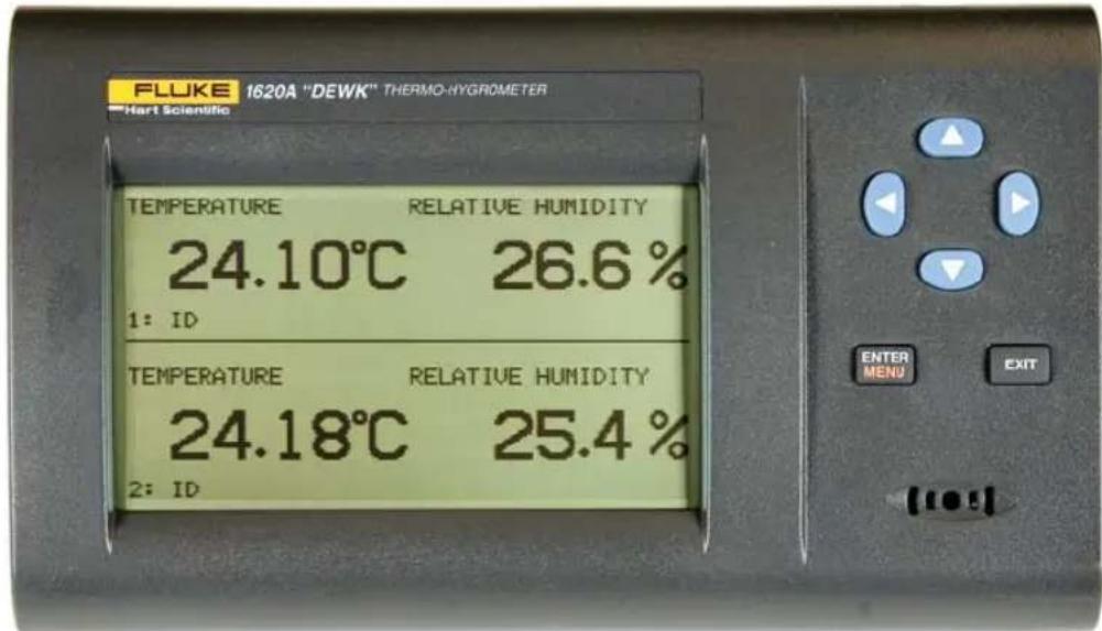
Figure 1 Front Panel
The buttons have different functions depending on whether the main screen or the menu system is displayed.
The functions of each of the buttons from the main screen are as follows:
Enter/Menu - This button is used to display the menu options.
Exit - This button is used to display the alarm window. With the alarm window displayed the Exit button can be used to return to the main screen while preserving the alarm events or the Enter button can be used to clear the alarm events and return to the main screen.
◀▶ - These buttons are used to move among enabled display layouts.
▲▼ - These buttons are used to adjust the display contrast, ▲ for darker and
▼for lighter.
The functions of each of the buttons within the menu system are as follows:
Enter/Menu - This button is used to select a menu item, to accept a choice, or save changes to a parameter.
Exit - This button is used to return from a menu or window or cancel changes to a parameter. Pressing the Exit button for a second or so returns from most any menu, menu function, or window back to the main screen.
▲▼ - These buttons are used to move among menu items or parameters. When editing some numeric or alpha-numeric parameters, these buttons are used to change a digit or character.
◀▶ - These buttons are used to change a value or option when editing a parameter. When editing some numeric or alpha-numeric parameters, these buttons are used to move among digits or characters.
5.2 Top Panel
The top panel contains the port for attaching the sensor for Channel 1. An optional extension cable may be used to allow the sensor to be placed in a remote location.
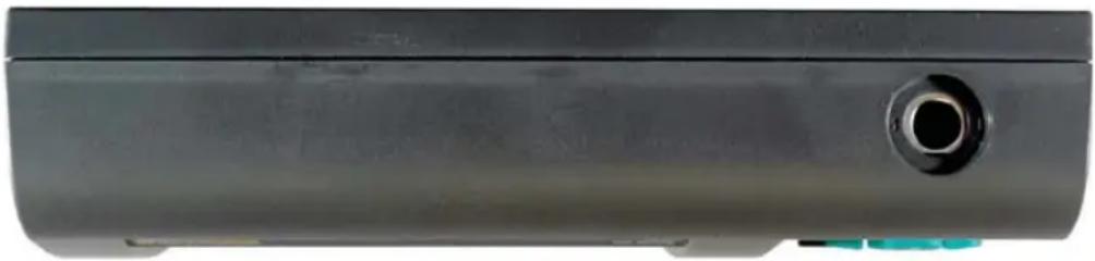
natural_image
Close-up of a black plastic car door with a circular vent and small blue clip (no text or symbols visible)Figure 2 Top Panel
5.3 Right Side Panel
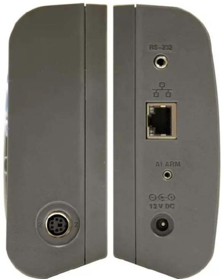
The right side panel contains the port for attaching the sensor for Channel 2.
An optional extension cable may be used to allow the sensor to be placed in a remote location.
natural_image
Two gray electronic device back panels with labeled ports and connectors, no readable text or symbols beyond labelsFigure 3 Right and Left Side View
5.4 Left Side Panel
The left side panel consists of, from top to bottom, the RS-232 port, Ethernet LAN port, alarm port, and DC power socket.
RS-232 Port - The RS-232 port can be used to connect the instrument to a computer and remotely control and retrieve data from the instrument using a serial RS-232 interface (see Sections 7.5.3.1 and 8). The jack accepts a 3.5 mm miniature stereo plug.
LAN Port - This RJ45 socket allows the instrument to be connected to an Ethernet IP computer network to remotely control and retrieve data from the instrument (see Sections 7.5.3.3 and 8). The port has two LED indicators. The
bottom LED indicates link state: off for no connection, amber for 10 Mbps, and green for 100 Mbps. The top LED indicates link activity: off for no activity, amber for half duplex, and green for full duplex.
Alarm Port - The alarm port allows external alarm indicators to be connected to the instrument and activated when an alarm event occurs (see Section 7.4.1). The port outputs 0V when inactive and 12V DC (up to 20 mA) when active. The jack accepts a 2.5 mm two-conductor subminature plug (Switchcraft #850). The sleeve of the plug is ground and the tip is positive.
DC Power Socket - The DC plug from the AC adapter plugs into the 12V DC power socket to power the instrument. The jack accepts a 5.5 mm miniature power plug (Switchcraft #S760). The outer conductor is ground and the inner conductor is positive. The instrument may draw up to 0.5A.
5.5 Back Panel
The back panel contains the stand, power switch, battery compartment, and product information, including serial number.
Stand - The stand can be used to prop up the thermo-hygrometer on a flat surface.
Battery Compartment - The battery compartment holds a 9V alkaline battery used as a backup power source to maintain continuous measurement during a power outage (see Section 6.2, Battery).
Power Switch - The power switch turns the power on and off to the thermo-hy-grometer, including power from the battery. Before disconnecting the AC adapter from the instrument, switch the power off to prevent draining the backup battery.
Serial Label - The serial label shows the instrument model and serial number.
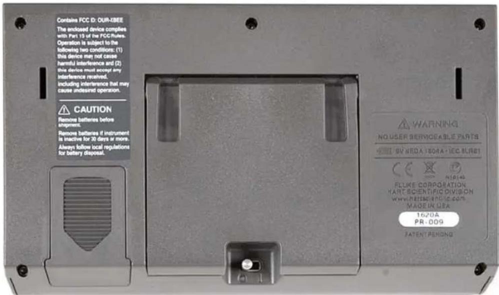
Figure 4 Back Panel (RF option shown)
5.6 Quick Buttons
When the main screen is displayed, the buttons have the following functions: Enter/Menu - This button is used to display the menu options.
Exit - This button is used to display the alarm window. With the alarm window displayed the Exit button can be used to return to the main screen while preserving the alarm events or the Enter button can be used to clear the alarm events and return to the main screen.
◀▶ - These buttons are used to move among enabled display layouts.
▲▼ - These buttons are used to adjust the display contrast, ▲ for darker and ▼ for lighter.
5.7 Configurations
- Model 1620A-H includes a 1620A-H Thermo-Hygrometer readout, a high accuracy sensor (Model 2626-H), a thermo-hygrometer readout wall mount bracket, power supply (Model 2361), and an RS-232 cable.
- Model 1620A-S includes a 1620A-S Thermo-Hygrometer readout, a standard accuracy sensor (Model 2626-S), a thermo-hygrometer readout wall mount bracket, power supply (Model 2361), and an RS-232 cable.
5.8 Accessories
The following accessories are available to compliment either the high accuracy or standard thermo-hygrometer readout.
• 2626-S Spare Sensor/Standard Accuracy
- 2627-S Spare Sensor Kit includes a standard accuracy probe (2626-S), sensor case (2607), sensor wall mount bracket (2630), and 25-foot (7.6 m) extension cable (2628)
• 2626-H Spare Sensor/High Accuracy
- 2627-H Spare sensor Kit includes a high accuracy sensor (2626-H), sensor case (2607), sensor wall mount bracket (2630), and 25-foot (7.6 m) extension cable (2628)
• 2607 Spare Sensor Protective Case
• 2628 Extension cable, 25-foot (7.6 m)
• 2629 Extension cable, 50-foot (15.2 m)
• 2630 Sensor wall mount bracket
- 9328 Protective Case (includes space for a 1620A Thermo-Hygrometer, two sensors, RS-232 cable, and power cord)
• 2361 Spare Power Supply, 100-240 VAC to 12 VDC
• 9936A LogWare III, single-PC license
• 9936A-L1 License, LogWare III, 1-pack
• 9936A-L5 License, LogWare III, 5-pack
• 9936A-L10 License, LogWare III, 10-pack
• 9936A-LST License, LogWare III, site
• 9936A-UPG Software, 9936A Upgrade from v1.X
- 2633-RF Option, Factory Installed Wireless, Dewk (Model 2633-USB or Model 2633-232 receiver required to communicate with this option)
• 2633-USB Receiver, USB to wireless (requires 2633-RF)
• 2633-232 Receiver, RS-232 to wireless (requires 2633-RF)
6 General Operation
This section explains basic operation of the thermo-hygrometer. Detailed operation of the thermo-hygrometer is explained in Sections 7 and 8. Section 7 explains the menu structure and the functions available in the menu structure and Section 8 explains the communications interface for operating the thermo-hygrometer remotely.
6.1 DC Power Source
The thermo-hygrometer requires 12V DC to operate. The AC adapter is provided to produce the DC power from an AC mains supply.

Caution: For CE compliance and for proper performance, use only the AC adapter shipped with the instrument by Hart Scientific. If the AC adapter needs to be replaced, contact Hart Scientific Authorized Service Center. The AC adapter has circuits with high voltages inside that could present danger of electric shock or fire if exposed. If the AC adapter is damaged in any way or becomes hot, discontinue use immediately, disconnect the adapter from any AC supply, and replace the adapter. Do not attempt to open, repair, or continue using a damaged or defective AC adapter.
The DC output from the AC adapter plugs into the 12 V DC power input on the left side of the instrument (see Figure 3 on page 15).
6.2 Battery
The thermo-hygrometer uses a 9V battery to maintain continuous measurement and recording during power outages. The recommended battery type is a standard 9V alkaline battery (NEDA 1604A or IEC 6LR61). During a power outage, or when the AC adapter is disconnected, the display will be inoperable but measuring will continue if the 9V battery is installed. If the alarm is enabled, the beeper will sound periodically to alert the user of the loss of external power. With a fresh alkaline battery, measuring will continue during a power outage for typically about 16 hours. During normal operation, the battery charge is regularly checked, and if the low battery alarm is enabled, the user will be alerted when the battery charge drops below approximately 50%. The battery charge level can be viewed with a display layout that includes a stat type zone with one of the fields set to BATT. To prevent inadvertent battery drain, remember to switch the power switch off when external power is disconnected and the thermo-hygrometer is not in use.
To install or replace the battery, follow these steps:
-
Switch the power off and unplug the DC power cord.
-
Turn the thermo-hygrometer over to access the rear battery compartment. Press down slightly on the battery cover and slide it out to remove it.
- Remove the old battery if one is in place by lifting it up at the bottom and pulling it out.
- Slide the new battery in at an angle, observing the proper polarity so the terminals mate correctly, then press the bottom of the battery down into the holder.
- Replace the battery cover.
- Replace the DC power cord and switch the power on.
Used batteries must be disposed of properly. See Section 1.2.1, Warnings.
6.3 Sensor Configuration
The thermo-hygrometer can be used with one or two sensors of either type attached at either of the two ports. Extension cables can be used with the sensors to allow the sensors to be placed at remote locations. The extension cables can be up to 30m (100 ft.) in length. When a sensor is attached, the thermo-hygrometer detects the sensor automatically, reads its calibration parameters, and begins to measure if the channel is enabled (see Section 6.9, Measuring).
6.4 Power Switch
To operate the thermo-hygrometer, slide the rear power switch to the ON ( | ) position. When the thermo-hygrometer is not being used, slide the power switch to the OFF ( ○ ) position before disconnecting the power source to preserve the battery.
6.5 Power On Self-Test
When power is turned on, the thermo-hygrometer performs a self-test, checking the system, sensors, sensor calibration parameters, memory, and buttons. If an error occurs, an error message is displayed. See Section 11, Troubleshooting for additional information on error messages.
6.6 Display Contrast
If the display appears too dark or too light, you can use the ▲ and ▼ buttons at the main screen to adjust the contrast. The contrast can also be adjusted from the DISPLAY SETTING menu (see Section 7.2.1, Display Setting).
6.7 Display
The thermo-hygrometer display is originally configured with six default display layouts enabled. The user can enable and configure any of the 16 display layouts to show a variety of data in numerical or graphical format (see Section 7.2.2, Display Layout). Enabled display layouts can be quickly selected from the main screen using the ◀ and ▶ buttons.
6.8 Alarm Screen
The Alarm Screen can be accessed from the main screen by pressing Exit or by entering the Alarm Menu (see Section 7.4, Alarm Menu). If enabled, the alarm screen will appear automatically when an alarm event occurs. When an alarm is displayed the event can be either hidden by pressing Exit or cleared by pressing Enter.
6.9 Measuring
The thermo-hygrometer will automatically make measurements on enabled channels at the set period when a sensor is attached. Channels are enabled using the CHANNEL SETTING function in the CHANNEL menu (see Section 7.3.1.1, Record Setting). The measurement period is also set with this function.
6.10 Unit of Temperature
The thermo-hygrometer is capable of displaying temperature in Celsius (C) or Fahrenheit (F). The unit of temperature applies to temperature measurements on either channel that are displayed, recorded, or printed. Recorded data is viewed or printed with the currently set unit of temperature. The unit of temperature is set using the DISPLAY SETTING function in the DISPLAY menu (see Section 7.2.1, Display Setting) or the SYSTEM SETTING function in the SYSTEM menu (see Section 7.5.1, System Setting).
6.11 Recording Measurements
The thermo-hygrometer will automatically record measurements on enabled channels at the set period. Recording is enabled using the RECORD SETTING function in the DATA RECORD sub-menu in the DATA menu (see Section 7.3.1.1, Record Setting). The record period is also set with this function.
6.12 Sensors
The standard-accuracy sensor and high-accuracy sensor are used to measure temperature and relative humidity. The sensors attach to the thermo-hygrometer by plugging into the top or side panel of the instrument.
The sensor contains a memory device that stores information about the sensor and automatically transfers this data to the thermo-hygrometer when the sensor is attached. This ensures that the settings used to measure and calculate temperature and humidity always match the sensor being used.

Caution: Sensors are fragile devices that can be easily damaged by mechanical shock, overheating, and exposure to fluids or dust. Damage may not be visibly apparent but nevertheless can cause drift, instability, and loss of accuracy. Observe the following precautions:
• DO NOT allow sensors to be dropped, struck, or stressed.
- DO NOT overheat sensors beyond their recommended temperature range.
- DO NOT expose sensors to harmful vapors, fumes, dust, or condensation.
- DO NOT allow sensors to come into direct contact with any fluids.
6.12.1 Sensor Accuracy
To achieve full accuracy with the thermo-hygrometer sensors, a few precautions should be noted.
First, consider that the sensor actually measures its own temperature, not necessarily the temperature of the air around it. Ideally, the sensor's temperature will be the same as the air, but they might be different under less than ideal conditions.
One such condition is when there is a source of radiated heat that is "seen" by the sensor. Radiated heat tends to heat up the sensor higher than the air around it (try shining a flashlight on the sensor from some distance away). Some sources of radiated heat to avoid are incandescent lamps, space heaters, and other high-temperature devices. If such objects cannot be eliminated, consider using a heat shield between the heat source and the thermo-hygrometer sensor.
The sensor can also be heated by warm objects close by, perhaps a wall that is slightly warmer than the air in the room or even another sensor placed next to it. For best results, allow adequate distance between the sensor and any objects that might be at a different temperature than the air.
Other considerations relate to the self-heating of the sensor. Since the sensor contains electronic circuits that release a small amount of heat, the sensor will naturally be slightly warmer than the air around it. The calibration of the sensor takes this self-heating into account and compensates for it. But, factors that alter the natural self-heating can cause errors in the measurement.
Self-heating does depend somewhat on the velocity of the air around the sensor. The sensor is calibrated in nearly still air. Different air velocities can cause differences in the measured temperature of the sensor: as much as ±0.06^ for velocities ranging from 0 to 10 cm/s. High velocities can cause even greater errors that can be as large as 0.15^ below the temperature measured at low veloci-
ties. Thus, it is recommended that the sensor be located where there is minimal air currents.
The self-heating of the sensor could also be altered by nearby objects that insulate the sensor from the air. Keep adequate air space around the sensor.
The self-heating of the sensor takes a few minutes to stabilize after the power to the thermo-hygrometer is switched on or the sensor is attached. For best results, allow 15 minutes for the sensor to settle after applying power.
The sensor takes some time to respond to large changes in temperature or humidity, such as, for instance, when the sensor is brought from a cold or humid location to a warm or dry one. Depending on the difference, the sensor can take several minutes to more than an hour to reach full accuracy after conditions have changed.
Finally, moisture condensing within the sensor can cause erroneous or invalid measurements. Condensation can occur if the sensor is brought from a warm, high-humidity environment to a colder temperature. This can be avoided by first moving the sensor into low-humidity air at the same temperature for about 30 minutes before it is placed at the lower temperature. If condensation does occur, the sensor should recover once it dries out. This may take several hours.
7 Menu Functions
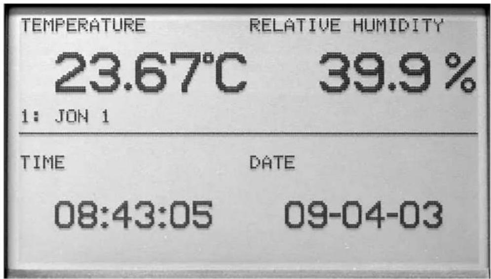
Figure 5 Main Display
Selecting the Enter/Menu button from the front panel accesses the main menu of the thermo-hygrometer. The main menu consists of the submenus: CHANNEL, DISPLAY, DATA, ALARM, and SYSTEM. Most of the menu options may be password-protected to prevent them from being changed (see Section 7.5.4, PASSWORD)
![T 23.66°C RH 39.9% 1 08:44:09 09-04-03 ↑ ↑ [CHANNEL] move to item ENTER accept item DATA EXIT return to menu ALARMS SYSTEM](/content/2026/05/829649/images/1c488c12b8e358a8e14321d5c1410e6638f902a4ce319ca0e2ca60d696cb4a46.jpg)
Figure 6 Main Menu
Each submenu has its own set of functions. The Enter/Menu button is used to select and execute menu choices. The ▲▼ buttons are used to scroll through the functions. The Exit button is used to return from a function to the previous menu. The Exit button may be pressed and held to quickly return to the main screen.
7.1 Channel Menu
The CHANNEL menu provides functions for selecting the channel, setting the sensor identification, setting the sensor lock, and setting the sensor calibration. The functions that appear in the CHANNEL menu are CHANNEL SETTING, SENSOR ID, SENSOR LOCK, and SENSOR CAL.
![T 23.67°C RH 40.3% 1 08:45:18 09-04-03 ↑ ▼ [CHANNEL] move to [SETTING] item ENTER ACCEPT item SENSOR ID SENSOR LOCK EXIT return to menu SENSOR CAL](/content/2026/05/829649/images/ff1610b28fcdbf6b8ded2a0c81fd4f45bf8c662acfbf23d1d4315f860b475ab2.jpg)
Figure 7 Channel Menu
7.1.1 Channel Setting
The CHANNEL SETTING function allows you to turn the channels on or off, set the measurement period, turn averaging on or off, and set the time over which the rate of change is calculated for measurements.
These settings may be password-protected to prevent them from being changed (see Section 7.5.4, PASSWORD).
The channels are turned on or off by selecting the channel and then the ON or OFF setting using the ◀▶ buttons.
MEA PER, measurement period, is the time interval at which the measurements are updated on the display. You may select between 1, 2, 5, 10, 15, and 30 seconds, 1, 2, 5, 10, 15, 20, and 30 minutes, or 1 hour for the measurement period. AVERAGE may be turned to ON or OFF. When average is on, the temperature
and humidity values displayed are averaged over the measurement period. When average is off, the displayed values are instantaneous measurements.
RATE T, rate time, determines the time interval over which the measurements are used to calculate the rate of change, and is selectable between 30 seconds, 1, 2, 5, 10, 15, 20, 30, 45 minutes, or 1 hour. The temperature rate is displayed in the RATE T field of a STATS display zone. The humidity rate is displayed in the RATE H field of a STATS display zone. (See Section 7.2.3.) If RATE T is 5 minutes or less, the rate of change is calculated as the average rate of change using all the measurements obtained during the past RATE T time. If RATE T is greater than 5 minutes, the rate of change is calculated using the most recent measurement and the measurement obtained RATE T time ago. If there are as yet insufficient measurements to calculate the rate of change, only dots are displayed in the RATE T or RATE H field.
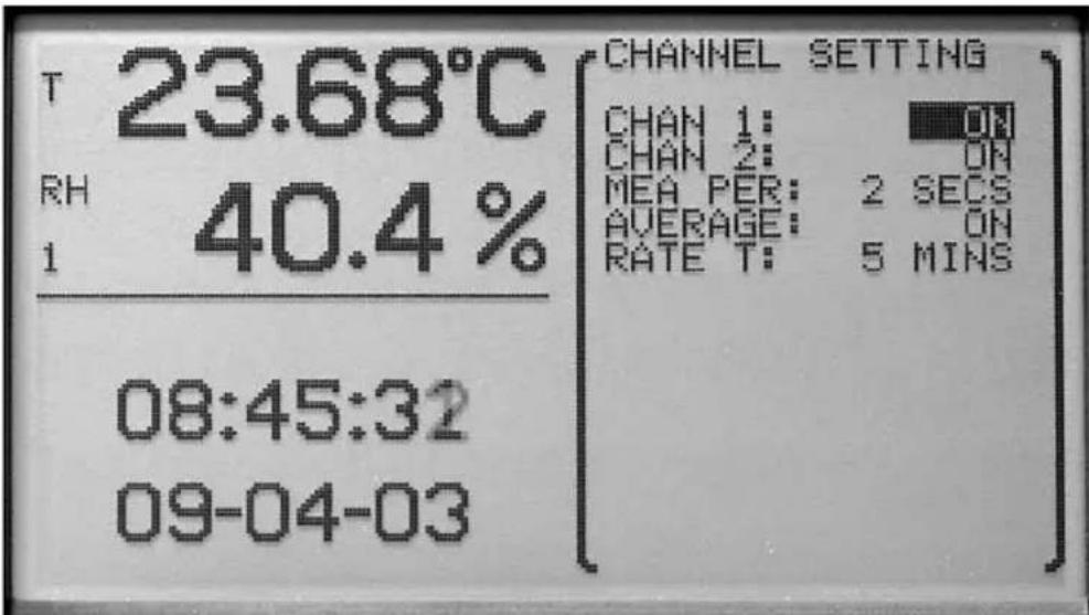
Figure 8 Channel Setting
Use the ▲▼ buttons to select the setting to change. The ◀▶ buttons are used to change the setting parameters. Press the Enter button to save the new setting. Press the Exit button to cancel any changes and exit to the menu.
7.1.2 Sensor ID
The SENSOR ID function allows each sensor to be uniquely identified. This may be password-protected to prevent it from being changed (see Section 7.5.4, PASSWORD). The model number and serial number are displayed here but
cannot be edited. The sensor ID cannot be set for a channel without a sensor attached. The sensor ID is stored in the sensor, not in the thermo-hygrometer.
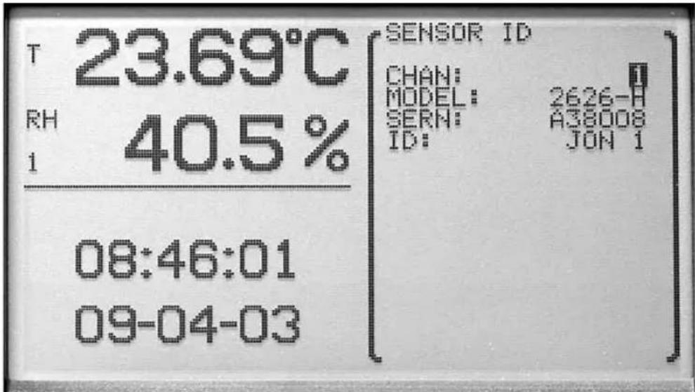
Figure 9 Sensor ID
Use the ◀▶ and ENTER buttons to select the sensor identification to change. The ◀▶ buttons are used to move among character positions and the ▲▼ buttons are used to change the character. Letters, numeric digits, space and underscore can be used. Press the Enter button to save the setting. Press the Exit button to cancel any changes and exit to the menu.
7.1.3 Sensor Lock
The SENSOR LOCK function locks each sensor individually and prohibits the user from switching sensors on the locked channels. This may be password-protected (see Section 7.5.4, PASSWORD). The sensor lock is set to ON or OFF. After selecting ON, a screen is displayed showing the sensor channel number, serial number, and the message 'NOW LOCKED'. When the sensor lock is ON, the thermo-hygrometer measures only on that channel using the sensor that was attached when sensor lock was set ON. This can be used to prevent inadvertent attachment of an uncalibrated sensor or one that is not in the
desired location. It uses the sensor serial number to identify the sensor. To exchange a different sensor, the sensor lock must be set to OFF.
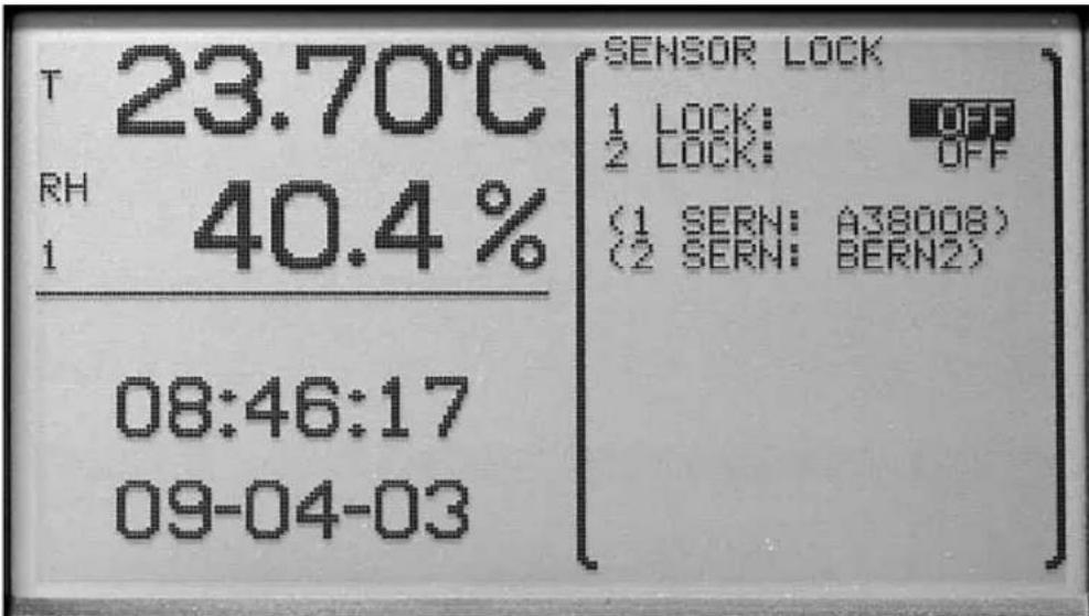
Figure 10 Sensor Lock
Use the ▲▼ buttons to select the sensor to lock. The ◀▶ buttons are used to select ON or OFF. Press the Enter button to save the setting and exit. Press the Exit button to cancel any changes and exit to the menu.
7.1.4 Sensor Cal
The SENSOR CAL function allows the sensor parameters to be edited. This function is always password-protected (see Section 7.5.4, PASSWORD). If an incorrect password or no password is entered, the parameters are displayed but cannot be edited. If a correct password is entered, the channel, sensor model, sensor serial number, and sensor ID are displayed. Select the sensor channel of the parameters to edit and then select the Enter button. The sensor parameters are displayed for editing.

Caution: The sensor calibration parameters are critical to the accuracy of the sensor. Do not change them (see Section 9, Calibration Procedure).
The ◀▶ buttons are used to select a channel. Press the Enter button to save
the setting and exit. Press the Exit button to cancel any changes and exit to the menu.
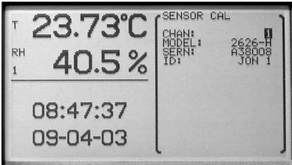
Figure 12 Sensor Channel Select
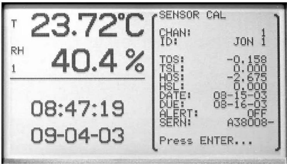
Figure 11 Sensor Cal
The ◀▶ buttons are used to edit the parameter value. The ▲▼ buttons are used to move between parameters. Press the Enter button after all of the pa-
rameters have been edited. The message 'STORE VALUES' is displayed. Press the Enter button to save the new settings. The values are stored in the sensor. Press the Exit button to cancel any changes and exit to the menu.
7.2 Display Menu
The DISPLAY menu provides functions for configuring the display. The functions that appear in this menu are DISPLAY SETTING, DISPLAY LAYOUT, FIELD DATA, GRAPH SCALE, and DISPLAY RESET.
![T 23.72°C RH 40.4% 1 08:48:19 09-04-03 ↑ ↑ [DISPLAY move to [SETTING] item ENTER DISPLAY accept LAYOUT item EXIT FIELD return DATA to menu GRAPH SCALE DISPLAY RESET](/content/2026/05/829649/images/89e7347fce1d31384387bf2fe40f7d8b11bf70e43d8ce919da086ac51df3519d.jpg)
Figure 13 Display Menu
7.2.1 Display Setting
The DISPLAY SETTING function allows you to select the temperature display resolution (T RES), humidity display resolution (H RES), decimal preference, unit of temperature and display contrast. These settings may be password-protected (see Section 7.5.4, Password).
The temperature and humidity display resolutions are selectable between 0, 0.1, 0.01, and 0.001. These settings do not affect the resolution of recorded or printed data. Recorded and printed data are fixed at 0.01^ or ^ and 0.1% RH.
The decimal preference is selectable between a period (.) and a comma (.),
The available units of measure are degrees C and degrees F.
The contrast can be adjusted here using the ◀▶ buttons. Setting the adjustment number more negative lightens the screen and setting it more positive
darkens the screen. The contrast may also be adjusted from the main screen by using the ▲▼ buttons (see Section 5.1, Front Panel).
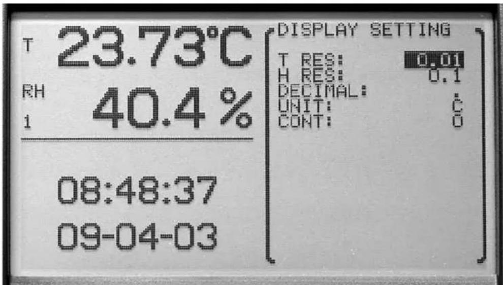
Figure 14 Display Setting
The ◀▶ buttons are used to select the parameter setting. The ▲▼ buttons are used to scroll between each parameter. Press the Enter button to change and save the new settings. Press the Exit button to cancel any changes and exit to the menu.
7.2.2 Display Layout
The DISPLAY LAYOUT function allows you to configure any of the 16 different display layouts. These settings may be password-protected (see Section 7.5.4, Password). A display layout can be enabled or disabled by choosing ON or OFF. ON allows the display to be selected from the main screen using the ◀▶ buttons. The number of zones is selectable from 1 to 4. Each zone can display one of the following zone types: blank screen, time, stats, temperature and humidity numerically, or temperature and humidity graphically. Once the number of zones is selected, you can select what is to be displayed in each zone.
The ◀▶ buttons are used to select the parameter setting. The ▲▼ buttons are used to move between each parameter. Press the Enter button to change and save the new settings. Press the Exit button to cancel any changes and exit to the menu.
The enabled layouts can be viewed by pressing the ◀▶ buttons when the main screen is displayed.
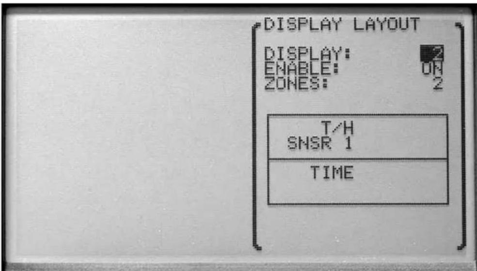
Figure 15 Display Layout
Except for blank and time types, zones require that a sensor number be selected. Data for the specified sensor number is displayed in the zone. The options for the zone type and descriptions for each follow:
Blank: No data is displayed.
TIME: The current time and date are displayed.
STATS: Various statistical values are displayed numerically for the given sensor. Statistical values to display can be selected using the FIELD DATA menu function (Section 7.2.3).
T/H: Temperature and humidity are displayed numerically for the given sensor.
T GRAPH: Temperature history is displayed on a graph for the given sensor. The temperature (vertical) scale, time (horizontal) scale, and number of grid divisions can be set for the zone using the GRAPH SCALE menu function (Section 7.2.4).
H GRAPH: Relative humidity history is displayed on a graph for the given sensor. The relative humidity (vertical) scale, time (horizontal) scale, and number of grid divisions can be set for the zone using the GRAPH SCALE menu function (Section 7.2.4).
Graphs include time tick marks that occur at hourly intervals for time scales 24 hours or less or at daily intervals for time scales greater than 1 day. Time tick marks are labeled at intervals with the hour or day, labels being placed below
and to the right of tick marks. Tick marks with labels are drawn with short continuous lines, and tick marks without labels are drawn with dotted lines.
Graphs are replotted when a different display layout is selected, a display layout's settings are changed, or graph scale settings are changed. Data for the graphs are extracted from recorded data in memory. If recording is disabled, graphs cannot be replotted and will appear empty until new data is collected.
7.2.3 Field Data
The FIELD DATA function allows you to select a type of statistic for any of the fields in a STAT type zone. This may be password-protected (see Section 7.5.4, Password). Select the display layout on which to adjust the statistics field type and then select the zone to adjust. This function can only be used with display layouts that contain STATS zones. There are eight fields per zone. Any field can be set to the following field types: DATE, TIME, ID, SERN, TEMP, T RATE, T AVE, T STD, T MIN, T MAX, T SPR, T N, T RMAX, T ALAR, T DELT, RHUM, H RATE, H AVE, H STD, H MIN, H MAX, H SPR, H N, H RMAX, H ALAR, H DELT, DEWP, HEAT, REC CH, BATT, MEAS, or BLANK. See Table 2 for a definition of each of these parameters.
Statistics fields show running statistics of the measurements taken since the last statistics reset. The statistics are reset automatically after power up, when the STATS RESET function is used (see Section 7.3.2.4), or when the time reaches the RESTIM hour and AUT RES is enabled for the DAILY STATS (see Section 7.3.2, Daily Stats).
Table 2 Statistics Zone Field Types
| Field Type Description | |
| Blank blank field | |
| DATE current date | |
| TIME current time | |
| ID sensor identification | |
| SERN sensor serial number | |
| TEMP most recent temperature measurement | |
| T RATE | temperature rate of change |
| T AVE | temperature statistical mean |
| T STD | temperature standard deviation |
| T MIN | minimum temperature |
| T MAX | maximum temperature |
| T SPR | temperature spread (maximum minus minimum) |
| T N | number of temperature statistical samples |
| T RMAX | maximum temperature rate of change |
| T ALAR | temperature alarm count |
| T DELT | temperature delta (difference from the other channel) |
| RHUM | most recent relative humidity measurement |
| H RATE | humidity rate of change |
| H AVE relative humidity statistical mean | |
| H STD relative humidity standard deviation | |
| H MIN minimum relative humidity | |
| H MAX maximum relative humidity | |
| H SPR | relative humidity spread (maximum minus minimum) |
| H N | number of humidity statistical samples |
| H RMAX | maximum relative humidity rate of change |
| H ALAR relative humidity alarm count | |
| H DELT | relative humidity delta (difference from the other channel) |
| DEWP | dew point (see ALT parameter in Section 7.1.1, Channel Setting) |
| HEAT | heat index (apparent temperature as felt by humans) |
| REC CH | recording channel/measurement type enable status |
| BATT battery level | |
| MEAS | seconds to next measurement |
| ---- | separating line |
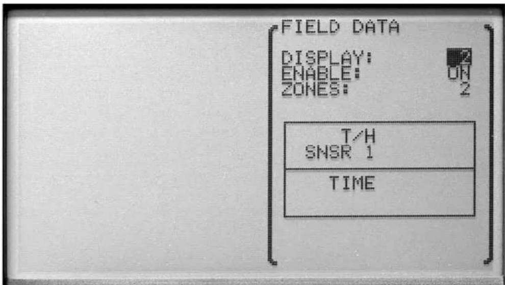
Figure 16 Field Data
Use the ◀▶ buttons to change each of the settings. Press Enter to save and continue to the next parameter. Press the Exit button to cancel any changes and exit to the menu.
7.2.4 Graph Scale
The GRAPH SCALE function allows the selection of the graph settings for each zone (1, 2, 3, or 4). Graph settings for each zone are used in common among all display layouts. This may be password-protected (see Section 7.5.4, Password). For each zone you may set the center of the vertical axes for the temperature graphs (T CENT), the temperature scale for the axes (T SCAL), the center of the vertical axes for the humidity graphs (H CENT), the humidity scale for the axes (H SCAL), the time axis scale (TIME), and the number of grid divisions for the graph (DIVS). Following is the range for each setting:
T CENT from 100.000 to -40.000
T SCAL from 100.000 to 0.100
H CENT from 100.000 to 0.000
H SCAL from 100.000 to 1.000
TIME from 1, 4, 10, 24 hours and 2, 5, 7, 15, 30 days
DIVS from 1,2,4,6,8,10
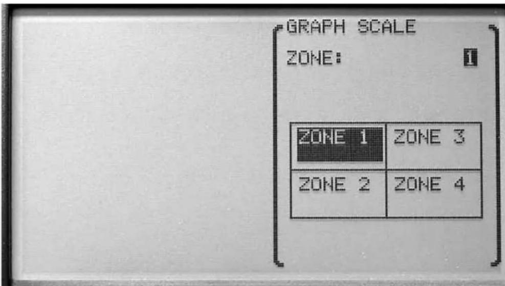
Figure 18 Graph Scale, Select Zone
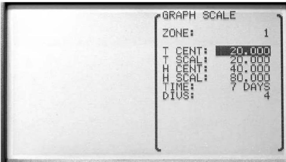
Figure 17 Graph Scale
Use the Enter button to edit and save the new setting. Press Exit button to cancel any changes and exit to the menu. On the last parameter, press the Enter button to exit to the menu.
7.2.5 Display Reset
The DISPLAY RESET function allows all display layouts, field data settings and graph scale settings to be reset to original settings. This may be password-protected (see Section 7.5.4, Password).
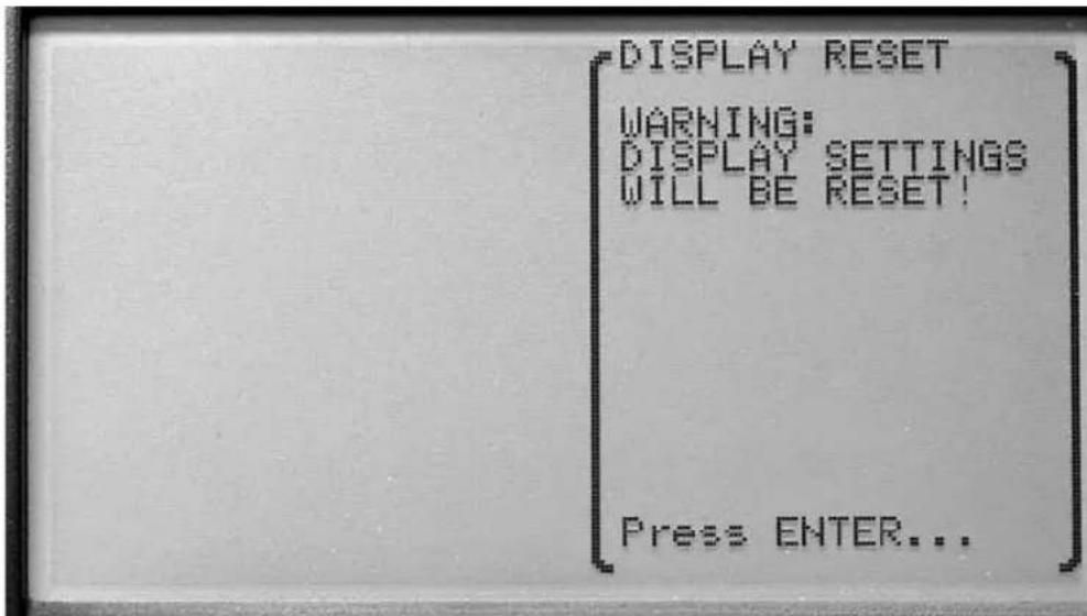
Figure 19 Display Reset
Use the Enter button to reset the display settings. Press the Exit button to cancel any changes and exit to the menu.
7.3 Data Menu
The DATA menu contains functions for recording measurement data and statistics.
The functions that appear in this menu are DATA RECORD and DAILY STATS.
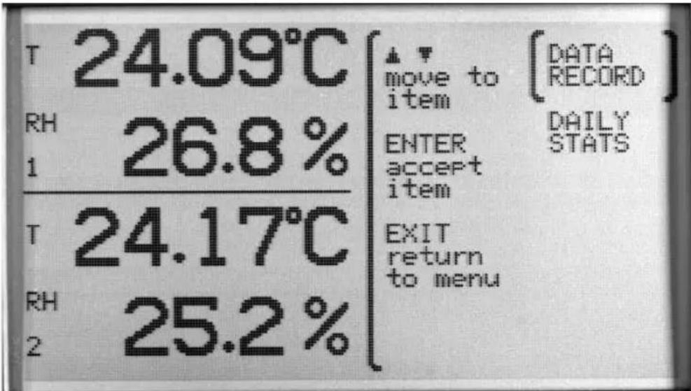
Figure 20 Data Menu
Use the ▲▼ buttons to select the menu. Press the Enter button to select the menu. Press the Exit button to cancel any changes and exit to the menu.
When recording is enabled, measurements are stored in memory at the set period. The data is highly compressed digitally to achieve a high storage density. This is done by storing data in blocks, headed by product and sensor identification and time information that applies to subsequent measurements up to the start of the next data block. A new data block is started when the thermo-hygrometer is powered on, when record setting parameters are changed, and when data is printed or written to a file. A new data block is also started when the date or time is set, when the date changes, and at regular intervals depending on the record period. Thus data blocks may contain various quantities of measurements.

CAUTION: When data recording memory fills up, the earliest block of data is automatically discarded so recording of the most recent data can continue.
7.3.1 Data Record
The DATA RECORD function allows the setting of the data recording features.
The functions that appear in this menu are RECORD SETTING, DATA VIEW, DATA PRINT, DATA STORAGE, and DATA CLEAR.
![↑ ↑ move to item ENTER accept item EXIT return to menu [RECORD SETTING] DATA VIEW DATA PRINT DATA STORAGE DATA CLEAR](/content/2026/05/829649/images/e1e3bc547e0ad551e1a99802b53838e8758ff85e4974f04225e431903fd09673.jpg)
Figure 21 Data Record
Use the ▲▼ buttons to select the menu. Press the Enter button to select the menu. Press the Exit button to cancel any changes and exit to the menu.
7.3.1.1 Record Setting
The RECORD SETTING function allows you to select what is to be recorded and how often the recording occurs. This may be password-protected (see Section 7.5.4, Password). The temperature and humidity from each channel can be recorded and the recording period is selectable.
To record the temperature on sensor channel 1, set REC 1/T to ON.
To record the humidity on sensor channel 1, set REC 1/H to ON.
To record the temperature on sensor channel 2, set REC 2/T to ON.
To record the humidity on sensor channel 2, set REC 2/H to ON.
The REC PER recording period is set by selecting 1, 2, 5, 10, 15, or 30 seconds, 1, 2, 5, 10, 20, or 30 minutes, or 1 hour for the REC PER.

Note: It is recommended that REC PER be set to 5 minutes or more; otherwise, the memory may fill up quickly and redrawing graphs may be slow. Also note that graphs can only be redrawn if the measurement for the channel is being recorded, as the graph data is obtained from recorded data. The recording period affects the observable time resolution of graphs.

Caution: When the memory has been filled, the oldest block of data will be discarded to allow new data to be recorded.
Measurement storage capacity can range between 28 hours and 2 years depending on the record period and enabled channels. Refer to Table 3, Approximate Data Storage Capacity.
Table 3 Approximate Data Storage Capacity
| Record period | Storage, 1 channel | Storage, 2 channels |
| 1 second 56 hours 28 hours | ||
| 10 seconds 20 days 10 days | ||
| 1 minute 18 weeks 9 weeks | ||
| 5 minutes 20 months 10 months | ||
| 10 minutes 24 months 20 months | ||
| 30 minutes 24 months 24 months | ||
| 1 hour | 24 months | 24 months |
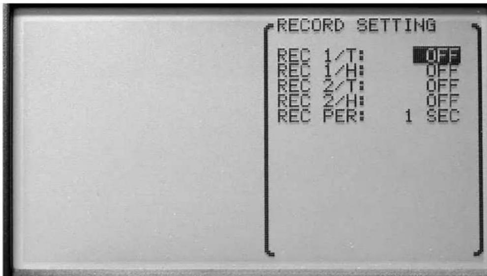
Figure 22 Record Setting
Use the ▲▼ buttons to select the setting to change. The ◀▶ buttons are used to change the setting parameters. Press the Enter button to save the new setting. Press the Exit button to cancel any changes and exit to the menu.
7.3.1.2 Data View
The DATA VIEW function allows viewing recorded data in NUMERIC or GRAPHIC format.
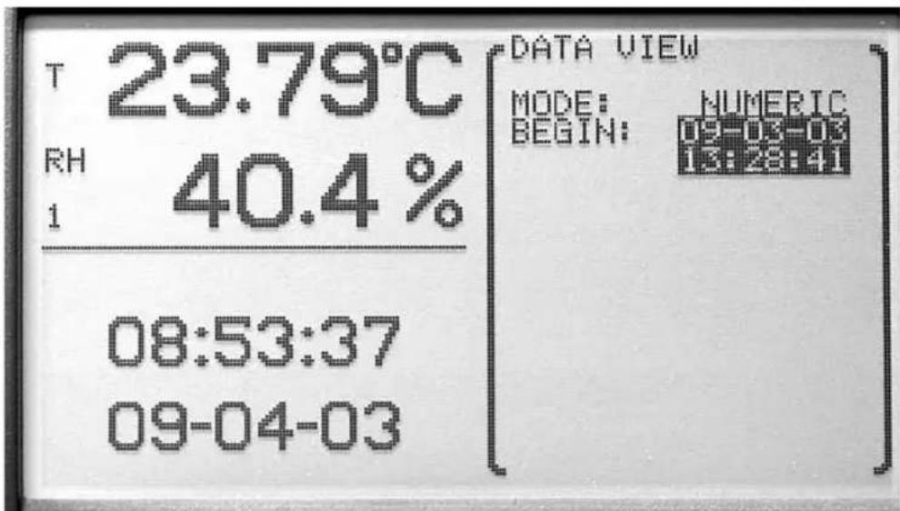
Figure 23 Data View, Begin Time
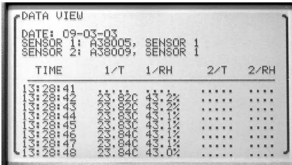
Figure 24 Data View, Numeric Format
The numeric mode displays the data in a numeric format. The BEGIN parameter specifies the starting date and time of the data to display. Use the ◀ but-
tons to adjust the start date and time. The format of the start date is according to D FORM in the SYSTEM, DATE-TIME menu function (see Section 7.5.2, Date Time). The format of the start time is 24 hour format.
Press the Enter button to display the data for the selected starting date and time. Use the ▲▼ buttons to scroll through the data (you can go back two screens) and the ◀▶ buttons to scroll among data blocks. Press the Exit button to cancel any changes and exit to the menu.
The graphic mode displays the data in a graphic format. The CHAN parameter allows you to select the channel from which to view the data. T CENT sets the center of the vertical axis for temperature. T SCAL sets the scale. H CENT sets the center of the vertical axes for humidity. H SCAL sets the scale. The TIME parameter is the length of data to display and may be set to 1, 4, 10, or 24 hours, 2, 5, 7, 15, or 30 days. The DIVS parameter is the number of divisions for the graph, and may be set to 1, 2, 4, 6, 8, or 10. The BEGIN parameter sets the start date and the start time. The format of the start date is according to the D FORM in the SYSTEM, DATE-TIME menu (see Section 7.5.2, Date Time). The format of the start time is 24 hour format.
Press the Enter button to display the data for the selected starting date and time in graphical format. Press the Exit button to cancel any changes and exit to the menu.
Every recorded measurement within the time span of a graph appears as a dot at the appropriate time location. If the time scale is small and the recording interval is large, dots will be separated.
Graphs include time tick marks that occur at hourly intervals for time scales 24 hours or less or at daily intervals for time scales greater than 1 day. Time tick marks are labeled at intervals with the hour or day, labels being placed below and to the right of tick marks. Tick marks with labels are drawn with short continuous lines, and tick marks without labels are drawn with dotted lines.
Dashed vertical cursor lines appear in the center of the graphs after they are plotted. The cursor can be moved left or right using the ◀ or ▶ buttons. Holding a button in moves the cursor quickly. Pressing ENTER locates the latest data point on or to the left of the cursor and causes the temperature, relative humidity, time, and date of the data point to be displayed. Press EXIT to quit and return to the menu.
7.3.1.3 Data Print
The DATA PRINT function allows recorded data to be printed over the serial port. The FORMAT parameter may be set to BINARY or TEXT. The BEGIN parameter sets the start date and the start time from which to start printing. The
format of the start date is according to D FORM in SYSTEM, DATE-TIME (Section 7.5.2). The format of the start time is 24 hour format.
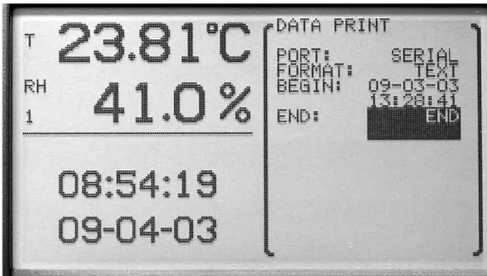
Figure 25 Data Print
The ◀▶ buttons are used to change the parameters. Press the Enter button to save the new setting.
Press the Exit button to cancel any changes and exit to the menu.
7.3.1.4 Data Storage
The DATA STORAGE function allows viewing the status of the data memory. The FILLED parameter shows the percentage of storage space used. The BYTES parameter shows the number of bytes stored. The CAP parameter shows storage capacity, in bytes. The INDEX parameter shows percentage of
space used in the record block index. The BEGIN parameter is the date of the earliest data. The END parameter is the date of the latest data.
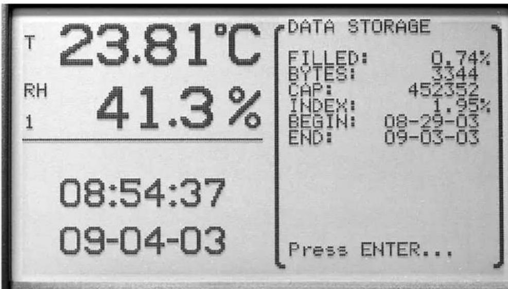
Figure 27 Data Storage
Press the Enter or Exit button to exit.
7.3.1.5 Data Clear
The DATA CLEAR function clears the data collected. This function may be password protected (see Section 7.5.4, Password).
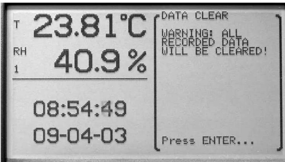
Figure 26 Data Clear
Press the Enter button to clear the data. Press the Exit button to cancel any changes and exit to the menu.

Caution: Using this function will erase all recorded data and make it irretrievable.
7.3.2 Daily Stats
The DAILY STATS menu can be used to record measurement statistics, such as average, maximum, minimum, maximum rate, etc., for each day. Up to 60 days of statistics are stored. Earliest statistics are erased automatically if needed to store another day's statistics. DAILY STATS can be set up to automatically store the running statistics on any hour of the day and automatically reset the statistics on any hour. Measurement statistics are kept as measurements are made. The current statistics can be displayed in any STATS type zone (see Sections 7.2.2 and 7.2.3). The statistics can also be stored automatically at the end of the day and reset automatically at the beginning of the next day. The DAILY STATS menu options are STATS SETTING, STATS VIEW,
STATS PRINT, STATS RESET, and STATS CLEAR. The DAILY STATS can be password-protected (see Section 7.5.4, Password).
![T 23.81°C RH 40.9% 1 08:55:06 09-04-03 ↑ ↑ [ STATS ITEM SETTING] ENTER STATIS accept VIEW item STATS EXIT STATS RETURN PRINT to menu RESET STATS STATS CLEAR](/content/2026/05/829649/images/32bbab7a9a129c956d64c6cb892ef4499584cb729994cae456283d9a73b41c83.jpg)
Figure 28 Daily Stats
The ▲▼ buttons are used to select the menu option. The ◀▶ buttons are used to change the setting parameters. Press the Enter button to save the new setting. Press the Exit button to cancel any changes and exit to the menu.
7.3.2.1 Stats Setting
The STATS SETTING function sets the daily statistics recording options. The AUT REC enables (ON) or disables (OFF) automatic recording of the statistics. The REC TIM may be set from 00:00 to 23:00. The REC TIM function sets the hour just prior to which the statistics are automatically recorded when AUT REC is ON. If REC TIM is 00:00, the statistics are recorded after the last measurement of the day.
AUT RES enables (ON) or disables (OFF) automatic reset of the statistics and may be set from 00:00 to 23:00. RES TIM sets the hour when the statistics are automatically reset if AUT RES is ON. If RES TIM is 00:00, the statistics are reset just prior to the first measurement of the day.
For example, to automatically store statistics for each day for measurements made in a laboratory only between 8:00 in the morning and 5:00 (17:00) in the afternoon, set the AUT REC to ON, REC TIM to 17:00, AUT RES to ON, and RES TIM to 08:00. Note that statistics can also be manually reset using the STATS RESET function (see Section 7.3.2.4). DO NOT manually reset the statistics if automatic recording is desired. The DAILY STATS settings and STATS RESET can be password-protected to prevent inadvertent resetting of the statistics (see Section 7.5.4, Password). DAILY STATS cannot be manually stored.
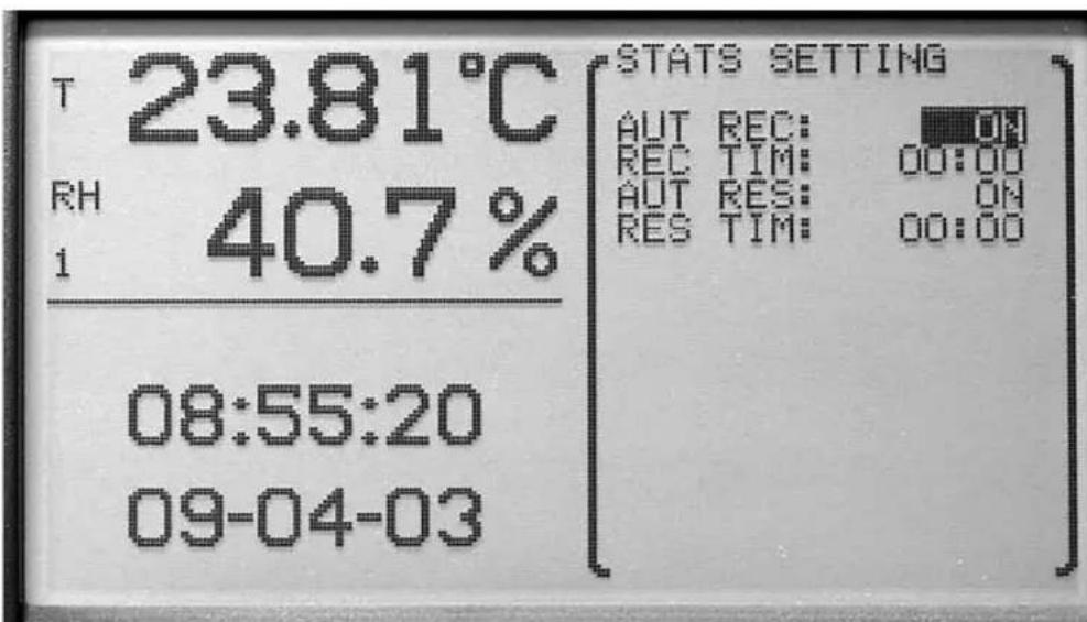
Figure 29 Stats Setting
The ◀▶ buttons are used to change the setting parameters. Press the Enter button to save the new setting. Press the Exit button to cancel any changes and to exit to the menu.
7.3.2.2 Stats View
The STATS VIEW function is used to view daily statistics. Select a date and measurement channel and type. The average, standard deviation, minimum, maximum, spread, number, maximum rate, and alarm are displayed for the channel and measurement type.
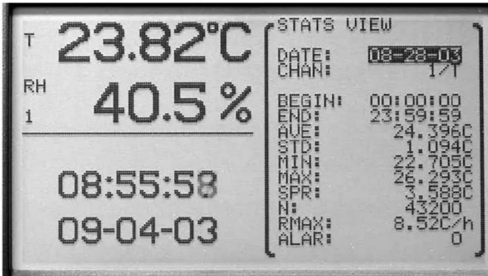
Figure 30 Stats View
The ◀▶ buttons are used to change the setting parameters. Press the Enter button to save the new setting. Press the Exit button to cancel any changes and exit to the menu.
7.3.2.3 Stats Print
The STATS PRINT function allows daily statistics to be printed over the serial port.
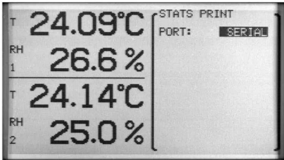
Figure 31 Stats Print
Press the Enter button to save the new setting. Press the Exit button to cancel any changes and exit to the menu.
7.3.2.4 Stats Reset
The STATS RESET function resets current statistics. Statistics will then be based on measurements made from this time forward. After pressing the Enter button, a WARNING message will appear requesting a confirmation of the op-
eration. If the Enter button is pressed the stats are reset. If the Exit button is pressed the operation is canceled.
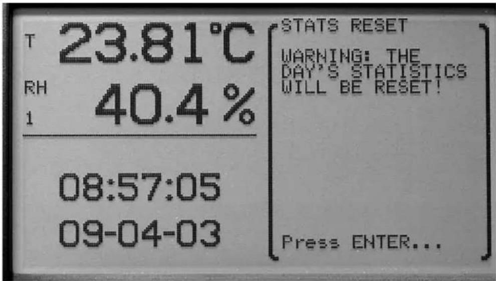
Figure 33 Stats Reset
7.3.2.5 Stats Clear
The STATS CLEAR function clears all daily statistics stored in memory. After pressing the Enter button, a WARNING message will appear requesting a confirmation of the operation. If the Enter button is pressed the stats are cleared. If the Exit button is pressed the operation is canceled.
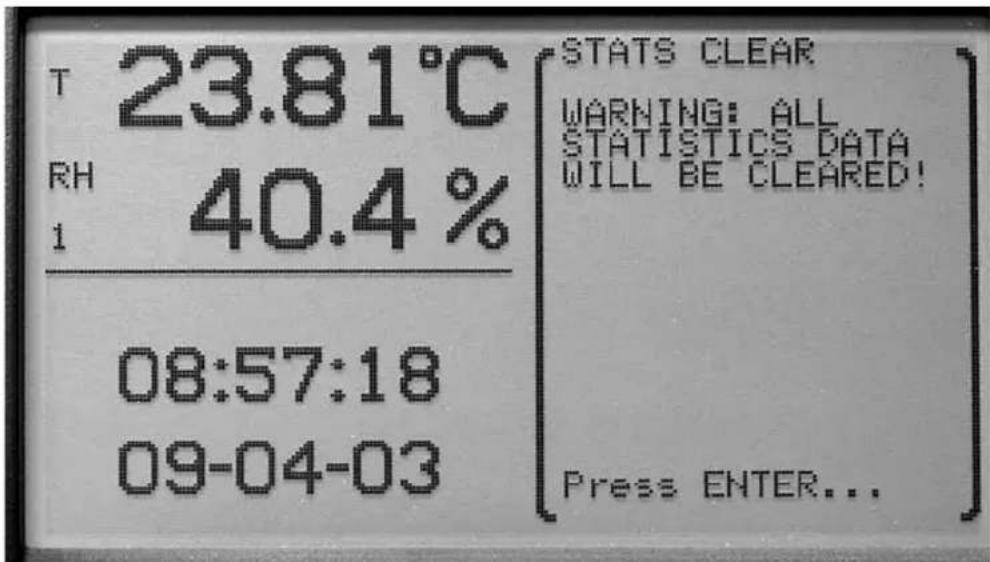
Figure 32 Stats Clear
7.4 Alarm Menu
The ALARM menu allows alarm event and indicator settings to be set and allows viewing of alarm events. The functions that appear in this menu are ALARM SETTING, SENSOR ALARM, SYSTEM ALARM, and ALARM VIEW. Alarm settings may be password protected (see Section 7.5.4, Password).
To enable alarms, first enable alarm indicators with ALARM SETTING as described below. Then enable specific alarm events with SENSOR ALARM for sensor or measurement related conditions or SYSTEM ALARM for system power conditions.
![T 21.82°C RH 29.1% I 22:03:19 09-04-2003 ↓ ↑ [ALARM move to [SETTING] item SENSOR ENTER ALARM accept SYSTEM item ALARM EXIT ALARM return to menu VIEW](/content/2026/05/829649/images/eaac7a6898eb578f6024f5d07d02cc8a10bd202363ef6a605b70068c6ecadf8b.jpg)
Figure 34 Alarm
The ▲▼ buttons are used to select the menu option. The ◀▶ buttons are used to change the parameter setting. Press the Enter button to save the new setting. Press the Exit button to cancel any changes made and exit to the menu.
7.4.1 Alarm Setting
The ALARM SETTING function is used to enable visual, audible, and external alarm indicators. The parameters are BEEP, DISPLAY, and PORT.
When the BEEP setting is ON, the thermo-hygrometer emits an audible beep to indicate an alarm event. For the power alarm it is four short beeps every 20 seconds. For the battery alarm it is three short beeps every minute. For the sensor disconnect alarm it is two short beeps every measurement period. For measurement alarms it is one long beep every measurement period.
When the DISPLAY setting is ON, an alert message is displayed when an alarm event occurs.
When the PORT setting is ON, the alarm port outputs an electrical signal to indicate that an alarm event has occurred. Under normal conditions the output will be 0V. When an alarm event occurs, and PORT is ON, the output will be driven at approximately 12V DC. The output remains active until alarms are reset (see Section 7.4.4, Alarm View). The alarm port is disabled while operating on internal battery power.
The alarm port may be connected to external indicator devices. The jack accepts a 2.5 mm two-conductor subminiature plug (Switchcraft #850). The sleeve of the plug is ground and the tip is positive. The port can source up to 20 mA of current.
As part of the start-up self-test performed when the instrument is switched on, the alarm port is briefly activated for approximately 50 ms (regardless of the PORT setting). This ensures that the alarm port is functioning.
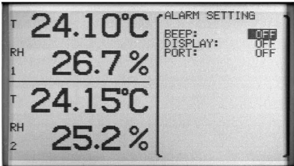
Figure 35 Alarm Setting
The ▲▼ buttons are used to select the menu option. The ◀▶ buttons are used to change the parameter setting. Press the Enter button to save the new setting. Press the Exit button to cancel any changes and exit to the menu.
7.4.2 Sensor Alarm
The SENSOR ALARM function enables various sensor-related alarms. For enabled sensor alarm events to be indicated, an indicator must be enabled with ALARM SETTING as described above.
To set alarm parameters, a channel number and measurement type (T or H) must first be selected using ◀▶ and ENTER buttons.
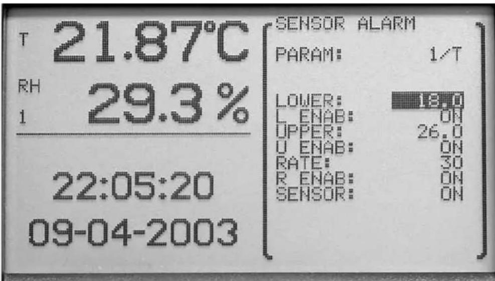
Figure 36 Sensor Alarm
The PARAM parameter is selectable between 1/T, 1/H, 2/T, 2/H. The 1 and 2 refer to the channel selected, T is temperature and H is humidity.
The ▲▼ buttons are used to select the menu option. The ◀▶ buttons are used to change the parameter setting. Press the Enter button to save the new setting. Press the Exit button to cancel any changes and exit to the menu.
Once an option is selected, the parameters LOWER, L ENAB, UPPER, U ENAB, RATE, R ENAB, and SENSOR for the given channel (1 or 2) and measurement type (T or H) are displayed. The LOWER parameter is the lower limit alarm. The L ENAB parameter is used to turn the lower limit alarm ON or OFF. The UPPER parameter is the upper limit alarm. The U ENAB parameter is used to turn the upper limit alarm ON or OFF. The RATE parameter is the upper limit of the absolute value of the rate of change expressed in degrees/hour or %RH/hour. The R ENAB parameter is used to turn the rate alarm ON or OFF. The SENSOR parameter is used to turn the sensor fault alarm ON or OFF.
The ▲▼ buttons are used to select the menu option. The ◀▶ buttons are used to change the parameter setting. Press the Enter button to save the new setting. Press the Exit button to cancel any changes and exit to the menu.
7.4.3 System Alarm
The SYSTEM ALARM function allows the battery or power alarms to be enabled. For enabled system alarm events to be indicated, an indicator must be enabled with ALARM SETTING as described above.
When the BATTERY alarm is turned ON, an alarm occurs when the battery charge is low.
When the POWER alarm is ON, an alarm occurs when power is disconnected, drops out, or is switched off. The beep indicator, if also enabled, will sound every 20 seconds when the instrument is operating from internal battery power, until external power is restored or the battery is drained.
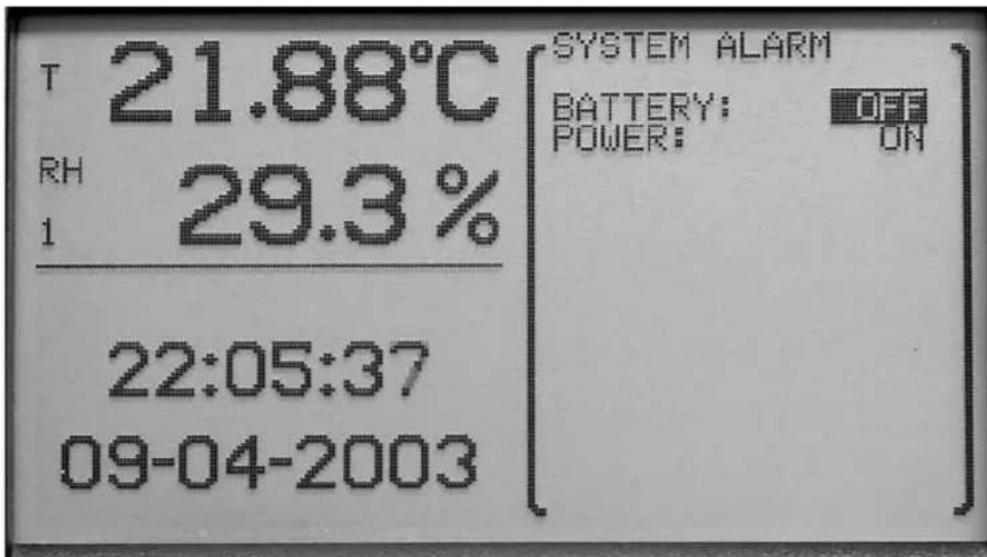
Figure 37 System Alarm
The ▲▼ buttons are used to select the menu option. The ◀▶ buttons are used to change the parameter setting. Press the Enter button to save the new setting. Press the Exit button to cancel any changes and exit to the menu.
7.4.4 Alarm View
The ALARM VIEW function displays the alarm event window (which can also be accessed from the main screen by pressing the Exit button). If alarm events have occurred, the word ALARM flashes at the top of the display and details about each alarm event is displayed.
Alarms for sensor low, high, or rate limits are indicated with the most extreme measurement (and the alarm limit setting). The times and dates of the earliest
and latest alarm events are shown below the list of alarm events (space permitting).
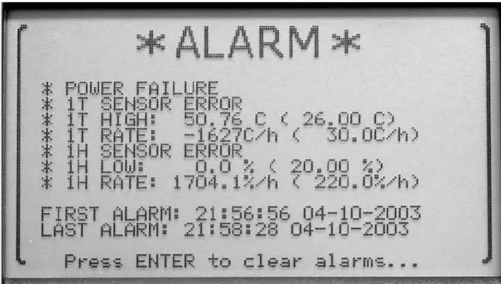
Figure 38 Alarm View
Press the Enter button to clear the alarms. Press the Exit button to retain any alarms and exit to the menu.
7.5 System Menu
The SYSTEM menu provides access to the general settings for the system such as temperature unit, date and time, the communication port settings, password settings, and viewing the system information. The functions that appear in this
menu are SYSTEM SETTING, DATE TIME, COMM SETTING, PASSWORD, and SYSTEM INFO.
![T 21.89°C RH 29.2% 1 22:06:20 09-04-2003 ↓ ↑ [SYSTEM move to [SETTING] item ENTER DATE accept TIME item COMM SETTING EXIT PASS- return to menu WORD SYSTEM INFO](/content/2026/05/829649/images/fbf5750bd0e7982ead4df99e1cd399ca80579188f867282df0afbbf786fd3f97.jpg)
Figure 39 System Menu
The ▲▼ buttons are used to select the menu option. The ◀▶ buttons are used to change the parameter settings. Press the Enter button to save the new setting. Press the Exit button to cancel any changes and exit to the menu.
7.5.1 System Setting
The SYSTEM SETTING function allows you to change the temperature measurement unit.
The UNIT parameter switches between C (Celsius) or F (Fahrenheit). This may be password protected with the SENSOR password parameter (see Section 7.5.4, Password).
When the measurement unit is changed and the Enter button is selected, the next measurement is displayed in the new measurement unit.
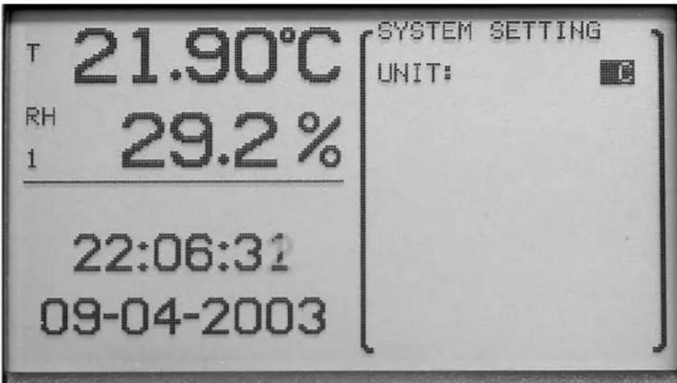
Figure 40 System Setting
The ◀▶ buttons are used to change the setting parameters. Press the Enter button to save the new setting. Press the Exit button to cancel any changes and exit to the menu.
7.5.2 Date Time
The DATE TIME function is used for setting the time-of-day clock, time format, date, and date format. This may be password protected using the TIME password parameter in the PASSWORD menu function (see Section 7.5.4, Password).
When this function is selected available parameters are HOUR, MINUTE, SECOND, T FORM, DAY, MONTH, YEAR, D FORM, and DAYL S.
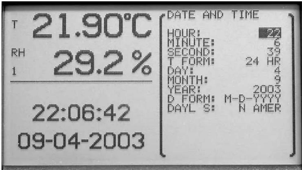
Figure 41 Date Time
The HOUR parameter allows the user to set the time-of-day clock hour (0 through 23).
The MINUTE parameter allows the user to set the time-of-day clock minutes (0 through 59).
The SECOND parameter allows the user to set the time-of-day clock seconds (0 through 59).
The T FORM parameter allows the user to set the time format used for displaying the time. The choices are 12-hour format or 24-hour format.
The DAY parameter allows the user to set the current day of the month (1-31).
The MONTH parameter allows the user to set the current month (1 - 12).
The YEAR parameter allows the user to set the current year (1999 through 9999).
The D FORM parameter allows the user to set the date format used when displaying the date. The choices are M-D-YY, M-D-YYYY, D/M/YY, and D/M/YYYY.
The DAYL S parameter allows the user to set the clock to automatically adjust for daylight saving shifts in the spring and fall. The choices are N AMER (United States and Canada), EUROPE, or OFF.
Be aware that automatic time changes due to the daylight saving time shift feature, and also manual time changes for that matter, will cause discontinuities in the time that may have unusual effects that should be noted.
One possible effect is with recorded daily stats. If the record time is reached twice within one day due to a time shift backwards, daily stats will be recorded twice for the same date. This can happen if the daily stats record time is set to 00:00, the daylight saving mode is set to Europe, and a fall backwards time shift occurs. Since the time 00:00 occurs twice for one day, two daily stats records will be created for the same day. It can also occur with the North America daylight saving mode if the daily stats record time is 01:00, since this time will occur twice in one day.
Another effect is with viewing data on a graph in real time. Data is plotted on the graph sequentially as measurements are made and the graph is scrolled uniformly. No adjustment is made to the real-time graph when the time changes. However, when a graph is redrawn (using recorded data, as a result of changing the display layout or cycling the power) in preparation to resume real-time plotting, the thermo-hygrometer attempts to accurately plot measurement points at the appropriate time locations. Thus, a one-hour spring daylight saving time shift will appear as a one-hour gap in the data on the graph. When a jump backwards is found in the recorded data, such as occurs during the fall daylight saving time shift, the thermo-hygrometer makes no attempt to plot the data prior to the time shift; there will appear to be missing data on the left side of the graph.
Graphs drawn using the DATA VIEW function behave similarly when time discontinuities occur in recorded data. A one-hour jump forward in time causes a one-hour gap in the data on the graph. However, a one-hour jump backwards in time produces a graph that also includes the data prior to the time shift. The repeated hour of data is also plotted but is compressed into one time point, the time just prior to the time shift. In other words, the data prior to the time shift is plotted first. Then when data for the first hour after the one-hour shift backwards is encountered, the data is plotted as if it all occurred at the instant of the time change. Then when the hour's data has passed, plotting resumes normally and the data is plotted to the right of the time shift.
Note that in any case data is recorded to memory as would be expected, with a one hour time gap or a repeated hour when a daylight saving time shift occurs. The effects of the automatic daylight saving time shifts should cause minimal inconvenience, as they occur early Sunday morning. To prevent confusion and time ambiguity problems, avoid running environment-sensitive operations during the daylight saving time shift. Also consider temporarily suspending data recording for days on which daylight saving time shifts occur. But if you do this, be sure to resume data recording when you need it!
The ▲▼ buttons are used to select the menu parameter. The ◀▶ buttons are used to change the parameters. Press the Enter button to save the new setting. Press the Exit button to cancel any changes and exit to the menu.
7.5.3 Comm Setting
The COMM SETTING function is used to setup the communication parameters for the communication ports. This may be password protected with the COMM password parameter (see Section 7.5.4, Password). Communication ports are
used for communicating with a computer, printer, or other equipment. The Thermo-Hygrometer includes a serial (RS-232) port, 802.15.4 (ZigBee) wireless (optional), and Ethernet LAN port. To edit the settings for a specific port it must first be selected. The selections are SERIAL, RF, LAN, and ERRORS.
The ERRORS setting allows the user to view any error messages stored in the error queue. Once an error has been viewed, it is removed from the error queue.
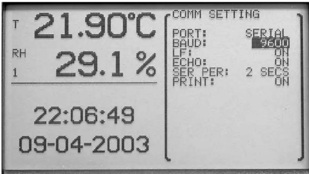
Figure 42 Comm Setting
The ◀▶ buttons are used to change the parameter setting. Press the Enter button to save the new setting. Press the Exit button to cancel any changes and exit to the menu.
7.5.3.1 Serial
The serial port can be used to receive and respond to commands from a remote
computer attached through a serial RS-232 cable. (See Section 8 for more information and for a list of commands.)
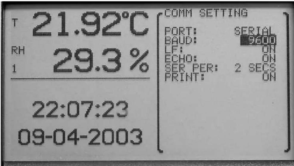
Figure 43 Serial
The BAUD parameter allows the user to select the baud rate for communications on this port. The user may choose between 1200, 2400, 4800, 9600, 19200, 38400, and 57600. The default baud rate is 9600.
The LF parameter allows the user to specify whether a linefeed character (ASCII 0A hex or 10 decimal) is appended to the end of each line transmitted over the serial port. Selecting ON sends both a carriage return (ASCII 0A hex or 13 decimal) and a linefeed. Selecting OFF sends only a carriage return.
The ECHO parameter allows the user to set the echo (duplex) mode. Selecting ON enables echoing so that all characters received on the serial port are echoed back over the serial port. Echo mode ON is useful when using terminal emulation software on a computer to communicate with the instrument. Selecting OFF disables echoing. Echo mode OFF is commonly used when using control software on the computer.
The SER PER parameter allows the user to select the interval at which measurements are automatically transmitted over the serial port. The user may choose between 1, 2, 5, 10, 15, and 30 seconds, 1, 2, 5, 10, 15, 20, and 30 minutes, and 1 hour.
The PRINT parameter allows the user to enable automatic printing of measurements over the serial port. Selecting ON enables printing and selecting OFF disables printing.
Press the ◀▶ buttons to change a parameter setting. Use the ▲▼ buttons to move between parameters. Press the Enter button to save the new setting. Press the Exit button to cancel any changes and exit to the menu.
7.5.3.2 RF (optional)
The RF wireless interface allows the instrument to receive and respond to commands from a remote computer through a radio-frequency wireless link. (See Section 8 for a list of commands.) The computer must be attached to an RS-232 or USB RF modem. See Section 5.8, Accessories, for more information. These accessories can be purchased separately. In the case of a USB RF modem, USB driver software supplied with the modem maps the wireless link to a virtual COM port on the computer. Proper communication between the instrument and a computer's RF modem requires that both be set with matched settings, as explained below.
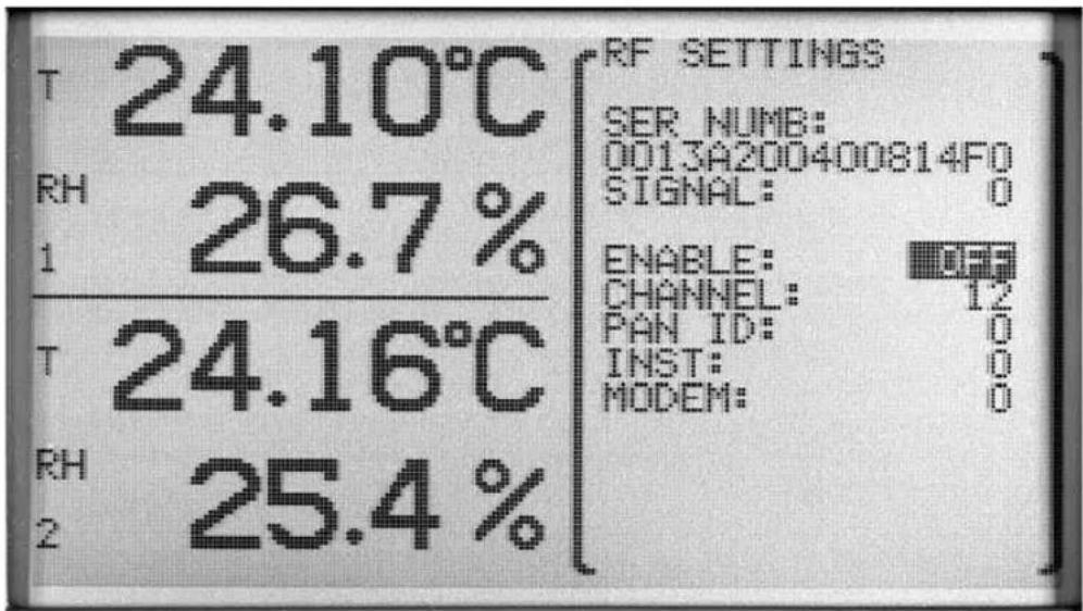
Figure 44 RF Settings
Figure 40: RF Settings MG_1420
Selecting RF for the PORT option in the COMM SETTING menu function presents a window containing the RF device settings, which include ENABLE, CHANNEL, PAN ID, INST, and MODEM. There might be a delay of several seconds as information is retrieved from the RF transceiver. The RF port option is only available if the wireless option has been purchased and is installed.
The unique serial number (SER NUMB) of the internal 802.15.4 wireless transceiver and the signal strength (SIGNAL) of the most recently received RF signal are displayed near the top of the window. For SIGNAL, the more negative the value the weaker the RF signal. For reliable communication, the received signal strength should be no weaker than -90 dB. Likewise, the signal received by the remote modem from the instrument should be no less than -90 dB.
ENABLE, when ON, switches on the RF transceiver. When RF is enabled, the LAN port will be disabled.
CHANNEL selects the frequency channel on which the RF transceiver operates. For two devices to communicate, they must use the same channel. Make sure the CHANNEL setting is set to the same number as the modem with which this instrument will be communicating. Frequencies used by RF communication may also be used by other types of equipment, with the potential for interference. The user might need to try different channels to find one that provides the most reliable operation in a particular environment. The range of CHANNEL is 12 to 24.
PAN ID sets the wireless network identification number. For two devices to communicate, they must use the same PAN ID number. Make sure PAN ID is set to the same number as the modem with which this instrument will be communicating. The range of PAN ID is 0 to 65535.
INST sets the identifying address of this instrument. The instrument will only accept commands that are addressed with this number. The remote modem will use this address to send commands to the instrument. This address should be distinct from those of other devices on the same network. The range of INST is 0 to 65535.
MODEM sets the address of the remote modem with which the instrument is to communicate. The instrument will send out responses addressed with this number. The remote modem must also be set to this address to receive the responses. The range of MODEM is 0 to 65535.
When the parameter window is exited, there might be a delay of several seconds as the RF transceiver is updated with the new settings.
Avoid communication conflicts by making sure all instruments in range of each other that operate with the same CHANNEL and PAN ID numbers have different INST addresses, and likewise all modems have addresses different from each other and all instruments. If multiple pairs of devices are to operate simultaneously in range of each other, use different CHANNEL numbers to avoid interference.
The RF interface is based on the 802.15.4 standard (which is the basis for the ZigBee). It operates in the license-free 2.4 GHz frequency band, with a very low transmission power of 1 mW. Typical unobstructed range is 100 ft. (30 m). The range might be reduced if RF-reflecting walls, obstructions, or interfering electronic equipment are nearby. Some channel numbers might work over farther ranges than others.
7.5.3.3 LAN
The LAN port allows the instrument to receive and respond to commands from a remote computer through an Ethernet IP network. (See Section 8 for a list of commands.) Redirector software can be installed on a computer to map the TCP/IP link with the instrument to a virtual COM port. Windows® Hyperterminal may also be used. Communications uses TCP port 10001. The
instrument can also serve a simple HTML or web page that allows readings to be observed with a web browser.
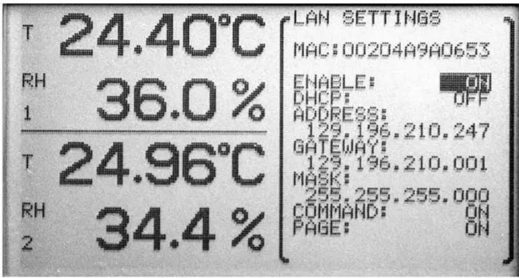
Figure 45 Lan Settings
Selecting LAN for the PORT option in the COMM SETTING menu function presents a window containing the LAN device settings, which include ENABLE, DHCP, ADDRESS, GATEWAY, MASK, COMMAND, and PAGE. There might be a delay of several seconds, when DHCP is enabled, as the dynamic address settings are read from the LAN port device.
The unique MAC number of the instrument's network interface is displayed.
ENABLE, when ON, switches on the LAN. When LAN is enabled, the RF device will be disabled.
DHCP, when ON, enables dynamic addressing. In this mode, the instrument's network IP address, gateway, and subnet mask are set automatically by the network server.
ADDRESS sets the network IP address of the instrument to be used when DHCP is off. When DHCP is on, this shows the dynamic address assigned by the network server.
GATEWAY sets the default gateway IP address to be used when DHCP is off. When DHCP is on, this shows the gateway address specified by the network server.
MASK sets the subnet mask to be used when DHCP is off. When DHCP is on, this shows the subnet mask specified by the network server.
COMMAND, when ON, enables access to settings using communication commands listed in Section 8. Password-protected settings still require the password for access. When COMMAND is OFF, settings can be read but not set,
even with th password. When using Hart Scientific's LogWare III Software, COMMAND must be ON for full functionality. With applications where extra security is important and settings need not be changed, COMMAND should be OFF.
PAGE, when ON, allows the instrument to serve an HTML web page. In applications where extra security is important, PAGE can be set to OFF disabling the HTML server.
When the parameter window is exited, there might be a delay of several seconds as the LAN port device is updated with the new settings.
The instrument does not implement dynamic DNS hostname registration.
When PAGE is enabled, the instrument serves a simple HTML web page that displays basic product information, allows readings to be observed, and provides a terminal screen where commands can be entered. The web page of the 1620A can be accessed with an internet browser using the instrument's IP address (see ADDRESS above) for the URL, e.g. http://192.168.1.1.
The main page shows product information, including the model and serial numbers of the instrument and its sensors and the ID (name) and calibration dates of the sensors. If a sensor's ALERT option is enabled, it also shows its calibration expiration date.
The READINGS button on the main page links to the Readings page which shows current temperature and relative humidity readings and alarm indications. The Update button refreshes the screen with new readings.
The TERMINAL button links to the Terminal page which allows any of the communication commands (see Section 8) to be entered and responses displayed. This page requires entering the instrument's password (see Section 7.5.4) before access is allowed. If the COMMAND option (see above) is OFF, commands can only be used to read settings but not change them. Groups of settings may also be password protected depending on PASSWORD parameter settings. The Terminal page opens a persistent TCP connection to the instrument, during which time no other access to the instrument through the LAN interface by any other computer is possible. The connection is closed when the Terminal page is exited.
7.5.4 Password
The PASSWORD function is used for changing the password required for access to password-protected parameters and for determining whether or not to password-protect those given parameters. When this function is selected, the PASS parameter is displayed.
The password must be entered correctly to access the password settings. Press the ◀▶ buttons to highlight the digit you want to change. Use the ▲▼ buttons to scroll through the numbers 0-9 to set each digit of the password. Press
the ENTER button to accept the password or press the EXIT button to cancel any changes and exit to the menu.
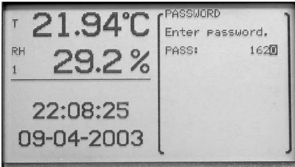
Figure 46 Password
By default the password is set to “1620” when the instrument ships from the factory. We recommend the user changes the default password to secure the password-protected settings.
NOTE: Keep your password in a secure location.
If an incorrect password is entered, the message WRONG PASSWORD is displayed and access to the password-protected parameters is denied. Press the ENTER button to reenter the password.
If a correct password is entered, the password-protected parameters PASS, SENSOR, RECORD, STATS, ALARM, TIME, and COMM are displayed.
The PASS parameter allows the user to change the password and consists of a four digit number.
The SENSOR parameter allows the user to turn the password-protection for sensor and channel settings ON or OFF.
The RECORD parameter allows the user to turn the password-protection for data recording settings ON or OFF.
The STATS parameter allows the user to turn the password-protection of statistics and daily stats settings ON or OFF.
The ALARM parameter allows the user to turn the password-protection of alarm settings ON or OFF.
The TIME parameter allows the user to turn the password-protection of time and date settings ON or OFF.
The COMM parameter allows the user to turn the password protection of the communications settings ON or OFF
Press the ◀▶ buttons to highlight the digit to change. Use the ▲▼ buttons to scroll through the numbers 0-9. Press the Enter button to save the new setting. Press the Exit button to cancel any changes and to move to the next parameter or exit to the menu.

Note: Keep your password in a secure location and do not forget the password.
7.5.5 System Info
The SYSTEM INFO function displays information about the thermo-hygrometer. The information includes the manufacturer, model number, serial number, firmware version, boot version, and battery level.
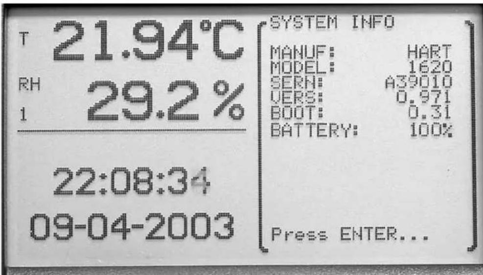
Figure 47 System Info
Press the Enter button when you are done viewing the system information or the EXIT button.
8 Digital Communications Interface
8.1 Overview
The communication features allow an external device, such as a computer, to communicate with the Thermo-Hygrometer readout to receive measurement data and control operating settings. Communication is accomplished by issuing commands to the Thermo-Hygrometer through an RS-232, RF wireless (optional), or Ethernet LAN interface.
8.1.1 Serial RS-232
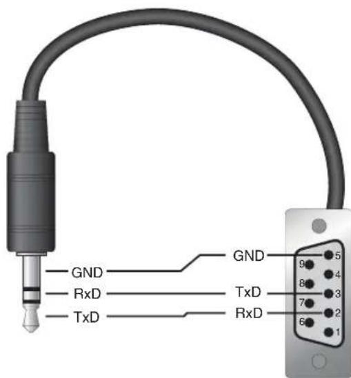
Figure 48 Serial Cable Wiring
A serial RS-232 interface allows connection between the instrument and a standard COM port on one computer or terminal through a three-conductor cable up to distances of 50 feet, typically.
The serial cable attaches to the Thermo-Hygrometer readout through the RS-232 port on the left side of the instrument. Figure 48 shows the pin-out of this connector and suggested cable wiring. Note the TxD line on one side connects to the RxD line on the other side and vice-versa. To avoid electromagnetic interference, the serial cable should be shielded with low resistance between the connector and the shield.
The serial period, baud rate, linefeed, and echo (duplex) are programmable. Refer to Section 7.5.3, Comm Setting, for instructions on setting these parameters.
8.1.2 RF Wireless (optional)
The RF wireless interface allows the instrument to receive and respond to commands from a remote computer through a radio-frequency wireless link. The computer must be attached to an RS-232 or USB RF modem. See Section 5.8, Accessories, for more information. These accessories can be purchased separately. In the case of a USB RF modem, USB driver software supplied with the modem maps the wireless link to a virtual COM port on the computer. Proper communication between the instrument and a computer's RF modem requires that both be set with matched settings, as explained in Section 7.5.3.2.
The RF interface uses the 802.15.4 standard (which is the basis for the ZigBee). It operates in the license-free 2.4 GHz frequency band, with a very low transmission power of 1 mW. Typical unobstructed range is 100 ft. (30 m). The range might be reduced if RF-reflecting walls, obstructions, or interfering electronic equipment are nearby. Some channel numbers might work over farther ranges than others.
8.1.3 LAN
The LAN interface allows the instrument to receive and respond to commands from a remote computer over an Ethernet IP network. Redirector software can be installed on a computer to map the TCP/IP link to a virtual COM port. Communications uses TCP port 10001. Windows® Hyperterminal may also be used. The settings for configuring and operating the LAN interface are explained in Section 7.5.3.3. Commands that might change operating settings can only be used if the COMMAND setting is ON.
The LAN interface operates on either a 10Base-T or 100Base-TX Ethernet IP network. A CAT 5 Ethernet cable attaches to the thermo-hygrometer readout at the RJ45 socket on the left side of the instrument. The RJ45 socket has two LED indicators. The bottom LED indicates link state: off for no connection, amber for 10 Mbps, and green for 100 Mbps. The top LED indicates link activity: off for no activity, amber for half duplex, and green for full duplex.
8.1.4 Command Syntax
The thermo-hygrometer readout accepts commands that set parameters, execute functions or respond with requested data. These commands are in the form of strings of ASCII-encoded characters. As far as possible, the thermo-hygrometer readout conforms to SCPI-1994. One notable exception is that compound commands are not allowed as explained below.
Commands consist of a command header and, if necessary, parameter data. All commands must be terminated with either a carriage return (ASCII 0D hex, 13 decimal) or new line character (ASCII 0A hex, 10 decimal).
Command headers consist of one or more mnemonics separated by colons (:). Mnemonics may use letter characters, the underscore character (_), and possibly numeric digits as well. Commands are not case sensitive. Mnemonics often
have alternate forms. Most mnemonics have a long form that is more readable and a short form consisting of three or four characters that is more efficient.
A mnemonic may end with a numeric suffix that specifies one of a set of independent function blocks such as input channel data paths. If a numeric suffix is omitted when a particular block must be specified, an error is generated (“Header suffix out of range”).
Query commands are commands that request data in response. Query commands have a question mark (?) immediately following the command header. Responses to query commands are generated immediately and transmitted over the communication interface. Responses are terminated with a carriage return (the serial interface can be configured to also send a new line character).
Many commands require parameter data to specify values for one or more parameters. The command header is separated from the parameter data by a space (ASCII 20 hex, 32 decimal). Multiple parameters are separated by a comma (,).
This instrument does not allow compound commands (multiple commands per line separated with semicolons). All commands are sequential; the execution of each command is completed before subsequent commands are processed. Some commands might take noticeable time to execute, during which time no other commands will be executed.
Incorrect or invalid commands produce error messages that are stored in the error queue. The error queue can be read using the command "SYST:ERR?" (also see Section 7.5.3, Comm Setting).
8.2 Commands
Table 4, Alphabetical List of Commands, lists the commands in alphabetical order. In this section the commands are arranged into the following groups:
Alarm Commands - commands for alarm settings.
Measurement Commands - commands for reading measurement data.
Data Commands - commands for setting and reading data information
Measurement Control Commands - commands for the timing and action of the measurement process.
Channel Commands - commands for selecting channels.
Calibration Commands - commands for calibration settings.
System Commands - commands for general system configuration parameters.
Communication Interface Commands - commands for controlling the interface configuration (serial, LAN, and optional RF ports).
Date and Time Commands - commands for setting the date, time and the date and time formats.
Table 4 Alphabetical List Commands
| Command Description Refer To | ||
| *CLS | Clear the status registers | Section 8.2.11.1 |
| *ESE? | Returns the Standard Event Status Enable register | Section 8.2.11.2 |
| *ESE | Sets the Standard Event Status Enable register | Section 8.2.11.3 |
| *ESR? | Returns the Standard Event Status register | Section 8.2.11.4 |
| *IDN? | Returns the instrument identification string that indicates the manufacturer, model number, serial number, and firmware version | Section 8.2.7.1 |
| *OPT? Returns configuration options Section 8.2.7.2 | ||
| *RST | Sets the instrument operating parameters to defined conditions | Section 8.2.7.3 |
| *SRE? | Returns the Service Request Enable register | Section 8.2.11.5 |
| *SRE | Sets the Service Request Enable register | Section 8.2.11.6 |
| *STB? | Returns the Status Byte register | Section 8.2.11.7 |
| *TST? [] | Returns the self-test results (0: startup test; 1: new test) | Section 8.2.11.8 |
| ALARm:BATTery? | Returns the battery alarm event | Section 8.2.1.1 |
| ALARm:BATTery:ENABLE? | Returns the state of the battery alarm enable | Section 8.2.1.2 |
| ALARm:BATTery:ENABLE | Enables or disables the battery alarm | Section 8.2.1.3 |
| ALARm:BEEP:ENABLE? | Returns the state of the alarm beep enable | Section 8.2.1.4 |
| ALARm:BEEP:ENABLE | Enables or disables the alarm beep | Section 8.2.1.5 |
| ALARm:CLEAR | Clears the alarm events | Section 8.2.1.6 |
| ALARm:DATE:FIRST? | Returns the date of the first alarm event | Section 8.2.1.7 |
| ALARm:DATE:LAST? | Returns the date of the latest alarm event | Section 8.2.1.8 |
| ALARm:DISPLAY:ENABLE? | Returns the state of the alarm display enable | Section 8.2.1.9 |
| ALARm:DISPLAY:ENABLE | Enables or disables the alarm display | Section 8.2.1.10 |
| ALARm:PORT? | Returns the alarm port state | Section 8.2.1.11 |
| ALARm:PORT | Sets the alarm port state | Section 8.2.1.12 |
| ALARm:PORT:ENABLE? | Returns the alarm port enable setting | Section 8.2.1.13 |
| ALARm:PORT:ENABLE | Sets the alarm port enable setting | Section 8.2.1.14 |
| ALARm:POWER? | Returns the power loss alarm event | Section 8.2.1.15 |
| ALARm:POWER:ENABLE? | Returns the state of the power loss alarm enable | Section 8.2.1.16 |
| ALARm:POWER:ENABLE | Enables or disables the power loss alarm | Section 8.2.1.17 |
| ALARm:RHUMidity:LOW? | Returns the state of the low humidity alarm for the specified channel | Section 8.2.1.18 |
| ALARm:RHUMidity:LOW:ENABLE? | Returns the state of the low humidity alarm enable for the speci-fied channel | Section 8.2.1.19 |
| ALARm:RHUMidity:LOW:ENABLE | Enables or disables the low humidity alarm enable for the speci-fied channel | Section 8.2.1.20 |
| ALARm:RHUMidity:RATE? | Returns the state of the humidity rate alarm for the specified channel | Section 8.2.1.23 |
| ALARm:RHUMidity:RATE:ENABLE? | Returns the state of the humidity rate alarm enable for the speci-fied channel | Section 8.2.1.24 |
| ALARm:RHUMidity:RATE:ENABLE | Enables or disables the humidity rate alarm for the specified channel | Section 8.2.1.25 |
| ALARm:RHUMidity:RATE:LIMit? | Returns the humidity rate alarm limit for the specified channel | Section 8.2.1.26 |
| ALARm:RHUMidity:RATE:LIMit | Sets the humidity rate alarm limit for the specified channel | Section 8.2.1.27 |
| IMINIMAXIDEF | ||
| ALARm:RHUMidity:SENSor? | Returns the state of the humidity sensor alarm for the specified channel | Section 8.2.1.28 |
| ALARm:RHUMidity:SENSor:ENABLE? | Returns the state of the humidity sensor alarm enable for the specified channel | Section 8.2.1.29 |
| ALARm:RHUMidity:SENSor:ENABLE | Enables or disables the humidity sensor alarm for the specified channel | Section 8.2.1.30 |
| ALARm:RHUMidity:UPPer? | Returns the state of the high humidity event for the specified channel | Section 8.2.1.31 |
| ALARm:RHUMidity:UPPer:ENABLE? | Returns the state of the high humidity alarm enable for the speci-fied channel | Section 8.2.1.32 |
| ALARm:RHUMidity:UPPer:ENABLE | Enables or disables the high humidity alarm for the specified channel | Section 8.2.1.33 |
| ALARm:RHUMidity:UPPer:LIMit? | Returns the high humidity alarm limit for the specified channel | Section 8.2.1.34 |
| ALARm:RHUMidity:UPPer:LIMit | Sets the high humidity alarm limit for the specified channel | Section 8.2.1.35 |
| IMINIMAXIDEF | ||
| ALARm:TEMPerature:LOW? | Returns the state of the low temperature alarm for the specified channel | Section 8.2.1.36 |
| ALARm:TEMPerature:LOW:ENABLE? | Returns the state of the low temperature alarm enable for the specified channel | Section 8.2.1.37 |
| ALARm:TEMPerature:LOW:ENABLE | Enables or disables the low temperature alarm for the specified channel | Section 8.2.1.38 |
| ALARm:TEMPerature:LOW:LIMit? | Returns the low temperature alarm limit for the specified channel | Section 8.2.1.39 |
| ALARm:TEMPerature:LOW:LIMit | Sets the low temperature alarm limit for the specified channel | Section 8.2.1.40 |
| IMINIMAXIDEF | ||
| ALARm:TEMPerature:RATE? | Returns the state of the temperature rate alarm for the specified channel | Section 8.2.1.41 |
| ALARm:TEMPerature:RATE:ENABLE? | Returns the state of the temperature rate alarm enable for the specified channel | Section 8.2.1.42 |
| ALARm:TEMPerature:RATE:ENABLE | Enables or disables the temperature rate alarm for the specified channel | Section 8.2.1.43 |
| ALARm:TEMPerature:RATE:LIMit? | Returns the temperature rate alarm limit for the specified channel | Section 8.2.1.44 |
| ALARm:TEMPerature:RATE:LIMit | Sets the temperature rate alarm limit for the specified channel | Section 8.2.1.45 |
| IMINIMAXIDEF | ||
| ALARm:TEMPerature:SENSor? | Returns the state of the temperature sensor alarm for the speci-fied channel | Section 8.2.1.46 |
| ALARm:TEMPerature:SENSor:ENABLE? | Returns the state of the temperature sensor alarm enable for the specified channel | Section 8.2.1.47 |
| ALARm:TEMPerature:SENSor:ENABLE | Enables or disables the temperature sensor alarm for the speci-fied channel | Section 8.2.1.51 |
| ALARM:TEMPerature:UPPer? | Returns the state of the high temperature alarm for the specified channel | Section 8.2.1.49 |
| ALARm:TEMPerature:UPPer:ENABLE? | Returns the state of the high temperature alarm enable for the specified channel | Section 8.2.1.50 |
| ALARm:TEMPerature:UPPer:ENABLE | Enables or disables the high temperature alarm for the specified channel | Section 8.2.1.51 |
| ALARm:TEMPerature:UPPer:LIMit? | Returns the high temperture alarm limit for the specified channel | Section 8.2.1.52 |
| ALARm:TEMPerature:UPPer:LIMit | Sets the high temperture alarm limit for the specified channel | Section 8.2.1.53 |
| IMINIMAXIDEF | ||
| ALARm:TIME:FIRST? | Returns the time of first alarm event | Section 8.2.1.54 |
| ALARm:TIME:LAST? | Returns the time of latest alarm event | Section 8.2.1.55 |
| CALibrate:ALERt? | Returns the state of the calibration alert enable for the specified channel | Section 8.2.6.1 |
| CALibrate:ALERt | Enables or disables the sensor alert enable for the specified channel | Section 8.2.6.2 |
| CALibrate:DATE:CALibrate? | Returns the sensor calibration date for the specified channel | Section 8.2.6.3 |
| CALibrate:DATE:CALibrate(,) | Sets the sensor calibration date for the specified channel | Section 8.2.6.4 |
| CALibrate:DATE:DUE? | Returns the sensor calibration due date for the specified channel | Section 8.2.6.5 |
| CALibrate:DATE:DUE(,) | Sets the sensor calibration due date for the specified channel | Section 8.2.6.6 |
| CALibrate:EXPiration? | Returns the sensor calibration expiration for the specified channel | Section 8.2.6.7 |
| CALibrate:PARameter:OFFSET? | Returns the sensor calibration offsets for the specified channel (temperature or humidity) | Section 8.2.6.8 |
| CALibrate:PARameter:OFFSET | Sets the sensor calibration offsets for the specified channel (temperature or humidity) | Section 8.2.6.9 |
| CALibrate:PARameter:SCALe? | Returns the sensor calibration scale for the specified channel (temperature or humidity) | Section 8.2.6.10 |
| CALibrate:PARameter:SCALe | Sets the sensor calibration scale for the specified channel (temperature or humidity) | Section 8.2.6.11 |
| CALCulate:AVERage:CLEar | Resets all running statistics | Section 8.2.2.1 |
| CALCulate:DEWPoint? | Returns the dew-point measurement for the specified channel | Section 8.2.2.2 |
| CALCulate:HINDex? | Returns the heat index measurement for the specified channel | Section 8.2.2.3 |
| CALCulate:PARame-ter:AVERerage? | Returns a running statistic for the specified channel | Section8.2.2.4 |
| CALCulate:PARameter:AVERerage:CLEar | Resets all running statistics | Section 8.2.2.5 |
| CALCulate:PARameter:AVERerage:DATA? | Returns a running statistic for the specified channel | Section 8.2.2.6 |
| CALCulate[:PARameter:AVERerage:TYPE? | Returns statistical type for the specified channel (temperature, humidity, type) | Section 8.2.2.7 |
| CALCulate:PARameter:RATE? | Returns rate calculation for the specified channel | Section 8.2.2.8 |
| CALCulate[:PARame-ter:RATE:TIME? | Returns the rate time span | Section 8.2.2.9 |
| CALCulate[:PARameter:RATE:TIME:MINIMAXIDEF | Sets the rate time span | Section 8.2.2.10 |
| CALCulate[:PARameter:RESolution? | Returns the display resolution | Section 8.2.2.11 |
| CALCulate<chn>:PARameter<num>:RESolution<num>IMINIMAXIDEF | Sets the display resolution) | Section 8.2.2.12 |
| DATa:DSTat:ENABLE? | Returns the state of the daily stats recording enable | Section 8.2.3.1 |
| DATa:DSTat:ENABLE | Enables or disables the daily stats recording enable | Section 8.2.3.2 |
| DATa:DSTat:HOUR? | Returns the daily stats recording time | Section 8.2.3.3 |
| DATa:DSTat:HOUR<num>IMINIMAXIDEF | Sets the daily stats recording time | Section 8.2.3.4 |
| DATa:DSTat:RENable? | Returns the state of the statistics reset enable | Section 8.2.3.5 |
| DATa:DSTat:RENable | Enables or disables the statistics reset | Section 8.2.3.6 |
| DATa:DSTat:RHOur? | Returns the statistics reset time | Section 8.2.3.7 |
| DATa:DSTat:RHOur<num>IMINIMAXIDEF | Sets the statistics reset time | Section 8.2.3.8 |
| DATa:DSTat:RE Cord:BTIMe? [<num>] | Returns the daily stats record begin time | Section 8.2.3.9 |
| DATa:DSTat:RE Cord:CLEar | Clears all daily stats records | Section 8.2.3.10 |
| DATa:DSTat:RE Cord:COUNt? [MAX] | Returns the daily stats record count | Section8.2.3.11 |
| DATa:DSTat:RE Cord:DATE? [<num>] | Returns the daily stats record date | Section 8.2.3.12 |
| DATa:DSTat:RE Cord:ETIMe? [<num>] | Returns the daily stats record end time | Section 8.2.3.13 |
| DATa:DSTat:RE Cord:FIND?[,,,,] | Returns the daily stats record number for the given date | Section 8.2.3.14 |
| DATa:DSTat:RE Cord:VALue?[,,,] | Returns the daily stats statistical calculation | Section 8.2.3.15 |
| DATa:RECord:CLEar | Clears all recorded data | Section 8.2.3.16 |
| DATa:RECord:FEED:RHUMidity? | Returns the state of the humidity recording for the specified channel | Section 8.2.3.17 |
| DATa:RECord:FEED:RHUMidity | Enables or disables the humidity recording for the specified channel | Section 8.2.3.18 |
| DATa:RECord:FEED:TEMPerature? | Returns the state of the temperature recording for the specified channel | Section 8.2.3.19 |
| DATa:RECord:FEED:TEMPerature | Enables or disables the temperature recording for the specified channel | Section 8.2.3.20 |
| DATa:RECord:FREE? | Returns the recording memory usage | Section 8.2.3.21 |
| DATa:RECord:OPEN? | Returns the number of bytes in the open data set | Section 8.2.3.22 |
| DATa:RECord:OPEN(<year>,,<month>,<day>,<hour>,<minute>[,,<year>,<month>,<day>,<hour>,<minute>,<second>) | Opens the range of data for reading | Section 8.2.3.23 |
| DATa:RECord:READ? [<num>] | Returns a group of data | Section 8.2.3.24 |
| DATa:RECord:TIMe? | Returns the data recording timer | Section 8.2.3.25 |
| DATa:RECord:TIMe<num>IMINIMAXIDEF | Sets the data recording timer | Section 8.2.3.26 |
| FETCH? [<chn>] | Returns the temperature and humidity measurements for the specified channel | Section 8.2.2.13 |
| FORMAT:TDSTamp:STAT? | Returns the state of the date/time stamp for FETCH,MEASure,or READ command | Section 8.2.2.14 |
| FORMAT:TDSTamp:STAT? | Enables or disables the date/time stamp for FETCH, MEASure,or READ command | Section 8.2.2.15 |
| INITiate | no action | Section 8.2.4.1 |
| INITiate:CONTinous? | Returns the continuous state (always 1) | Section 8.2.4.2 |
| MEASure? [] | Returns the temperature and humidity measurements for the specified channel | Section 8.2.2.16 |
| READ? [] | Returns the temperature and humidity measurements for the specified channel | Section 8.2.2.17 |
| ROUTE:CLOSE? [] | Returns the state of the specified channel | Section 8.2.5.1 |
| ROUTE:CLOSE | Enables the specified channel | Section 8.2.5.2 |
| ROUTE:OPEN? [] | Returns the channel state | Section 8.2.5.3 |
| ROUTE:OPEN | Disables the specified channel | Section 8.2.5.4 |
| SENSor:AVERAGE? | Returns the state of the measurement averaging | Section 8.2.4.3 |
| SENSor:AVERAGE | Enables or disables the measurement averaging | Section 8.2.4.4 |
| SENSor:LOCK? | Returns the state of the sensor lock for the specified channel | Section 8.2.4.5 |
| SENSor:LOCK | Enables or disables the sensor lock for the specified channel | Section 8.2.4.6 |
| SENSor:IDENTification? | Returns the sensor identification for the specified channel | Section 8.2.4.7 |
| SENSor:IDENTification | Sets the sensor identification for the specified channel | Section 8.2.4.8 |
| SENSor:STATUS? | Returns the sensor status for the specified channel | Section 8.2.4.9 |
| STATUS:ALARm? | Returns and clears the alarm status event | Section 8.4.11.9 |
| STATUS:ALARm:CONDITION? | Returns the alarm status condition | Section 8.2.11.10 |
| STATUS:ALARm:ENABLE? | Returns the alarm status enable | Section 8.2.11.11 |
| STATUS:ALARm:ENABLE | Sets the alarm status enable | Section 8.2.11.12 |
| STATUS:MEASure? | Returns and clears the measurement status event | Section 8.2.11.13 |
| STATUS:MEASure:CONDITION? | Returns the measurement status condition | Section 8.2.11.14 |
| STATUS:MEASure:ENABLE? | Returns the measurement status enable | Section 8.2.11.15 |
| STATUS:MEASure:ENABLE | Sets the measurement status enable | Section 8.2.11.16 |
| STATUS:OPERation? | Returns and clears the operation status event | Section 8.2.11.17 |
| STATUS:OPERation:CONDITION? | Returns the operation status condition | Section 8.2.11.18 |
| STATUS:OPERation:ENABLE? | Returns the operation status enable | Section 8.2.11.19 |
| STATUS:OPERation:ENABLE | Sets the operation status enable | Section 8.2.11.20 |
| STATUS:QUESTION? | Returns and clears the questionable status event | Section 8.2.11.21 |
| STATUS:QUESTION:CONDITION? | Returns the questionable status condition | Section 8.2.11.22 |
| STATUS:QUESTION:ENABLE? | Returns the questionable status enable | Section 8.2.11.23 |
| STATUS:QUESTION:ENABLE | Set the questionable status enable | Section 8.2.11.24 |
| SYSTem:BEEP | Produces a short beep from the speaker | Section 8.2.7.4 |
| SYSTem:BOOT:VERSION? | Returns the boot ROM version | Section 8.2.7.5 |
| SYSTem:COMM:RADio:CHANnel? | Returns the RF transceiver channel number | Section 8.2.8.1 |
| SYSTem:COMM:RADio:CHANnel | Sets the RF transceiver channel number | Section 8.2.8.2 |
| SYSTem:COMM:RADio:ENABLE? | Returns the RF transceiver enable state | Section 8.2.8.3 |
| SYSTem:COMM:RADio:ENABLE | Sets the RF transceiver enable state | Section 8.2.8.4 |
| SYSTem:COMM:RADio:INSTRument? | Returns the RF transceiver instrument address | Section 8.2.8.5 |
| SYSTem:COMM:RADio:INSTRument | Sets the RF transceiver instrument address | Section 8.2.8.6 |
| SYSTem:COMM:RADio:MODem? | Returns the RF transceiver modem address | Section 8.2.8.7 |
| SYSTem:COMM:RADio:MODem | Sets the RF transceiver modem address | Section 8.2.8.8 |
| SYSTem:COMM:RADio:OPTION? | Returns RF wireless installation status | Section 8.2.8.9 |
| SYSTem:COMM:RADio:PAN? | Returns the RF transceiver PAN ID address | Section 8.2.8.10 |
| SYSTem:COMM:RADio:PAN | Sets the RF transceiver PAN ID address | Section 8.2.8.11 |
| SYSTem:COMM:RADio:SIGNal? | Returns the RF transceiver signal strength | Section 8.2.8.12 |
| SYSTem:COMM:RADio:SNUMber? | Returns the RF transceiver serial number | Section 8.2.8.13 |
| SYSTem:COMMunica:SERial:BAUD? | Returns the serial port baud rate | Section 8.2.8.14 |
| SYSTem:COMMunica:SERial:BAUD | Sets the serial port baud rate | Section 8.2.8.15 |
| IMINIMAXIDEF | ||
| SYSTem:COMMunica:SERial:FDUPlex? | Returns the state of the serial port echo | Section 8.2.8.16 |
| SYSTem:COMMunica:SERial:FDUPlex | Enables or disables the serial port echo | Section 8.2.8.17 |
| SYSTem:COMMunica:SERial:FEED? | Returns the state of the serial port auto printing | Section 8.2.8.18 |
| SYSTem:COMMunica:SERial:FEED | Enables or disables the serial port auto printing | Section 8.2.8.19 |
| SYSTem:COMMunica:SERial:LINefeed? | Returns the state of the serial port linefeed | Section 8.2.8.20 |
| SYSTem:COMMunica:SERial:LINefeed | Enables or disables the serial port linefeed | Section 8.2.8.21 |
| SYSTem:COMMunica:SERial:TIMe? | Returns the serial port auto printing timer | Section 8.2.8.22 |
| SYSTem:COMMunica:SERial:TIMe | Sets the serial port auto printing timer | Section 8.2.8.23 |
| IMINIMAXIDEF | ||
| SYSTem:COMM:SOCKET:ADDRess? | Returns the LAN port IP address | Section 8.2.8.24 |
| SYSTem:COMM:SOCKET:ADDRess | Sets the LAN port IP address | Section 8.2.8.25 |
| SYSTem:COMMunicate:SOCKET:COMMAND? | Returns the status of the settings commands | Section 8.2.8.26 |
| SYSTem:COMM:SOCKET:DHCP? | Returns the LAN port DHCP setting | Section 8.2.8.27 |
| SYSTem:COMM:SOCKET:DHCP | Sets the LAN port DHCP setting | Section 8.2.8.28 |
| SYSTem:COMM:SOCKET:ENABLE? | Returns the LAN port enable state | Section 8.2.8.29 |
| SYSTem:COMM:SOCKET:ENABLE | Sets the LAN port enable state | Section 8.2.8.30 |
| SYSTem:COMM:SOCKET:GATeway? | Returns the LAN port IP gateway address | Section 8.2.8.31 |
| SYSTem:COMM:SOCKET:GATeway | Sets the LAN port IP gateway address | Section 8.2.8.32 |
| SYSTem:COMM:SOCKET:HTML? | Returns the HTML web page status | Section 8.2.8.33 |
| SYSTem:COMM:SOCKET:MAC? | Returns the LAN port hardware MAC address | Section 8.2.8.34 |
| SYSTem:COMM:SOCKET:MASK? | Returns the LAN port subnet mask | Section 8.2.8.35 |
| SYSTem:COMM:SOCKET:MASK | Sets the LAN port subnet mask | Section 8.2.8.36 |
| SYSTem:DATE? | Returns the clock date | Section 8.2.9.1 |
| SYSTem:DATE(,) | Sets the clock date | Section 8.2.9.2 |
| SYSTem:DATE:FORMAT? | Returns the display date format (0: mm-dd-yy; 1: mm-dd-yyyy; 2: dd/mm/yy; 3: dd/yy/yyyy) | Section 8.2.9.3 |
| SYSTem:DATE:FORMAT | Sets the display date format | Section 8.2.9.4 |
| SYSTem:DECimal:FORMAT? | Returns the display decimal option (0: ‘; 1: ‘,’) | Section 8.2.9.5 |
| SYSTem:DECimal:FORMAT | Sets the display decimal option | Section 8.2.9.6 |
| SYSTem:ERRor? | Returns the system error log | Section 8.2.7.6 |
| SYSTem:KLOCkout? | Returns the state of the button panel lockout | Section 8.2.8.37 |
| SYSTem:KLOCkout | Enables or disables the button panel lockout | Section 8.2.8.38 |
| SYSTem:PASSword:ALARm? | Returns the state of the alarm settings password protection | Section 8.2.10.1 |
| SYSTem:PASSword:ALARm | Enables or disables the alarm settings password protection | Section 8.2.10.2 |
| SYSTem:PASSword:CDISable | Disables password-protected commands | Section 8.2.10.3 |
| SYSTem:PASSword:CENable | Enables password-protected commands | Section 8.2.10.4 |
| SYSTem:PASSword:CENable:STATe? | Returns the current password-protected state | Section 8.2.10.5 |
| SYSTem:PASSword:COMM? | Returns the state of the communication settings password protection | Section 8.2.10.6 |
| SYSTem:PASSword:COMM | Enables or disables the communication settings password protection | Section 8.2.10.7 |
| SYSTem:PASSword:NEWIDEF | Sets the new password | Section 8.2.10.8 |
| SYSTem:PASSword:RE Cord? | Returns the state of the data recording password protection | Section 8.2.10.9 |
| SYSTem:PASSword:RE Cord | Enables or disables the data recording password protection | Section 8.2.10.10 |
| SYSTem:PASSword:SENSor? | Returns the state of the sensor settings password protection | Section 8.2.10.11 |
| SYSTem:PASSword:SENSor | Enables or disables the sensor settings password protection | Section 8.2.10.12 |
| SYSTem:PASSword:STATistics? | Returns the state of the statistics settings password protection | Section 8.2.10.13 |
| SYSTem:PASSword:STATistics | Enables or disables the state of the statistics settings password protection | Section 8.2.10.14 |
| SYSTem:PASSword:TIME? | Returns the state of the date/time password protection | Section 8.2.10.15 |
| SYSTem:PASSword:TIME | Enables or disables the date/time password protection | Section 8.2.10.16 |
| SYSTem:POWer:BATTery? | Returns the battery level percent | Section 8.2.8.39 |
| SYSTem:TIME? | Returns the clock time | Section 8.2.9.7 |
| SYSTem:TIME(,) | Sets the clock time | Section 8.2.9.8 |
| SYSTem:TIME:DAYLight? | Returns the automatic daylight saving adjustment setting | Section 8.2.9.9 |
| SYSTem:TIME:DAYLightIMINIMAXIDEF | Sets the automatic daylight saving adjustment setting | Section 8.2.9.10 |
| SYSTem:TIME:FORMAT? | Returns the display time format | Section 8.2.9.11 |
| SYSTem:TIME:FORMATIMINIMAXIDEF | Sets the display time format | Section 8.2.9.12 |
| SYSTem:VERSION? | Returns the SCPI version number | Section 8.2.7.8 |
| TRIGger:TIMe? | Returns the measurement period | Section 8.2.4.10 |
| TRIGger:TIMeIMINIMAXIDEF | Sets the measurement period | Section 8.2.4.11 |
| UNIT:TEMPerature? | Returns the temperature unit | Section 8.2.7.9 |
| UNIT:TEMPerature | Sets the temperature unit | Section 8.2.7.10 |
Password Commands - commands for enabling and disabling the password, for setting the password, and for checking the password protection state.
Status Commands - commands to report the status and condition of the instrument.
Each section provides the command structure (long and short format), a description of the command purpose, a command example, an example of what the command returns (as applicable to query commands), and notes specific to the command. The following apply to each group of commands:
- Upper case letters designate syntax that is required when issuing the command. Lower case letters are optional and may be omitted.
- <> indicates a required parameter.
- [] indicates an optional parameter.
- () indicates a group of parameters that must be used together.
- ‘l’ indicates alternate parameter values.
indicates a string of ASCII characters is required. indicates a channel number is required. indicates an integer value is required. indicates a boolean value (0 or 1) is required. The mnemonics OFF and ON are also accepted for 0 and 1, respectively. indicates a temperature unit (C or F) is required. indicates a floating point value is required. indicates a four digit numeric password is required. indicates a four digit number for the year is required. indicates a one or two digit number for the month is required. indicates a one or two digit number for the day is required. indicates a one or two digit number for the hour (0 to 23) is required. indicates a one or two digit number for the minute is required. indicates a one or two digit number for the second is required. indicates a valid baud rate setting is required. indicates an IP address is required. - For query commands, specifying the MIN, MAX, or DEF parameter causes the instrument to respond with the minimum, maximum, or default setting respectively.
- For set commands, specifying the MIN, MAX, or DEF parameters causes the instrument to use the minimum, maximum, or default setting respectively.
- Unrecognized commands or commands with incorrect syntax or invalid parameters generate error messages that are placed in the error queue (see Section 8.2.7.6, SYST:ERR?).
8.2.1 Alarm Commands
Indicates whether a battery alarm event has occurred.
Example: ALAR:BATT?
Response: 1
A value of 1 is returned if a battery alarm event has occurred. A value of 0 is returned if a battery alarm event has not occurred.
8.2.1.2 ALARm:BATTery:ENABLE?
Returns the state of the battery alarm enable.
Example: ALAR:BATT:ENAB?
Response: 0
A value of 1 is returned if the battery alarm is enabled. A value of 0 is returned if the battery alarm is disabled.
8.2.1.3 ALARm:BATTery:ENABLE
Sets the state of the battery alarm enable.
Example: ALAR:BATT:ENAB 1
The
8.2.1.4 ALARm:BEEP:ENABLE?
Returns the state of the audible alarm enable.
Example: ALAR:BEEP:ENAB?
Response: 0
A value of 1 is returned if the alarm beep is enabled. A value of 0 is returned if the alarm beep is disabled.
8.2.1.5 ALARm:BEEP:ENABLE
Sets the state of the audible alarm enable.
Example: ALAR:BEEP:ENAB 1
The
8.2.1.6 ALARm:CLEar
Clears the alarm events.
Example: ALAR:CLE
The alarm clear command clears the alarm events.
8.2.1.7 ALARm:DATE:FIRST?
Returns the date of the first alarm event.
Example: ALAR:DATE:FIRS?
Response: 2003,8,10
The response is returned in the format,
If no alarm has been triggered, the response is: 2000,0,0.
8.2.1.8 ALARm:DATE:LAST?
Returns the date of the last alarm event.
Example: ALAR:DATE:LAST?
Response: 2003,8,10
The response is returned in the format,
If no alarm has been triggered, the response is: 2000,0,0.
8.2.1.9 ALARm:DISPLAY:ENABLE?
Returns the state of the visible alarm enable.
Example: ALAR:DISP:ENAB?
Response: 0
A value of 1 is returned if the alarm display is enabled. A value of 0 is returned if the alarm display is disabled.
8.2.1.10 ALARm:DISPLAY:ENABLE
Sets the state of the visible alarm enable.
Example: ALAR:DISP:ENAB 1
The
8.2.1.11 ALARm:PORT?
Returns the alarm port state.
Example: ALAR:PORT:ENAB?
Response: 0
A value of 1 is returned if the alarm port is active (12V), 0 otherwise (0V).
8.2.1.12 ALARm:PORT
Sets the alarm port state.
Example: ALAR:PORT:ENAB 1
The
8.2.1.13 ALARm:PORT:ENABLE?
Returns the alarm port enable setting.
Example: ALAR:PORT:ENAB?
Response: 0
A value of 1 is returned if the alarm port is enabled. A value of 0 is returned if the alarm port is disabled.
8.2.1.14 ALARm:PORT:ENABLE
Sets the alarm port enable setting.
Example: ALAR:PORT:ENAB 1
The
8.2.1.15 ALARm:POWer?
Indicates whether a power loss alarm event has occurred.
Example: ALAR:POW?
Response: 0
A value of 1 is returned if a power loss alarm event has occurred. A value of 0 is returned if a power loss alarm event has not occurred.
8.2.1.16 ALARm:POWer:ENABLE?
Returns the state of the power loss alarm enable.
Example: ALAR:POW:ENAB?
Response: 0
A value of 1 is returned if the power loss alarm is enabled. A value of 0 is returned if the power loss alarm is disabled.
8.2.1.17 ALARm:POWer:ENABLE
Sets the state of the power loss alarm enable.
Example: ALAR:POW:ENAB 1
The
8.2.1.18 ALARm:RHUMidity:LOWer?
Indicates whether a lower humidity alarm event has occurred for the specified channel.
Example: ALAR:RHUM1:LOW?
Response: 0
The RHUMidity suffix,
8.2.1.19 ALARm:RHUMidity:LOWER:ENABLE?
Returns the state of the lower humidity alarm enable for the specified channel.
Example: ALAR:RHUM1:LOW:ENAB?
Response: 0
The RHUMidity suffix,
8.2.1.20 ALARm:RHUMidity:LOWER:ENABLE
Sets the state of the lower humidity alarm enable for the specified channel.
Example: ALAR:RHUM1:LOW:ENAB 1
The RHUMidity suffix,
8.2.1.21 ALARm:RHUMidity:LOWer:LIMit? [MIN|MAX|DEF]
Returns the lower humidity alarm limit for the specified channel in %RH.
Example: ALAR:RHUM1:LOW:LIM?
Response: 20.00
The RHUMidity suffix,
8.2.1.22 ALARm:RHUMidity:LOWer:LIMit |MINIMAX|DEF
Sets the lower humidity alarm limit for the specified channel in \%RH.
Example: ALAR:RHUM1:LOW:LIM 25.00
The RHUMidity suffix,
8.2.1.23 ALARm:RHUMidity:RATE?
Indicates whether a humidity rate alarm event has occurred for the specified channel.
Example: ALAR:RHUM1:RATE?
Response: 1
The RHUMidity suffix,
8.2.1.24 ALARm:RHUMidity:RATE:ENABLE?
Returns the state of the humidity rate alarm enable for the specified channel.
Example: ALAR:RHUM1:RATE:ENAB?
Response: 0
The RHUMidity suffix,
8.2.1.25 ALARm:RHUMidity:RATE:ENABLE
Sets the state of the humidity rate alarm enable for the specified channel.
Example: ALAR:RHUM1:RATE:ENAB 1
The RHUMidity suffix,
This command may be password protected (see Section 8.2.10, Password Commands).
8.2.1.26 ALARm:RHUMidity:RATE:LIMit? [MIN|MAX|DEF]
Returns the humidity rate alarm limit for the specified channel in \%RH per hour.
Example: ALAR:RHUM1:RATE:LIM?
Response: 5
The RHUMidity suffix,
8.2.1.27 ALARm:RHUMidity:RATE:LIMitIMINIMAXIDEF
Sets the humidity rate alarm limit for the specified channel in %RH per hour.
Example: ALAR:RHUM1:RATE:LIM 1
The RHUMidity suffix,
8.2.1.28 ALARm:RHUMidity:SENSOR?
Indicates whether a humidity sensor alarm event has occurred for the specified channel.
Example: ALAR:RHUM1:SENS?
Response: 1
The RHUMidity suffix,
8.2.1.29 ALARm:RHUMidity:SENSOR:ENABLE?
Returns the state of the humidity sensor alarm enable for the specified channel.
Example: ALAR:RHUM1:SENS:ENAB?
Response: 0
The RHUMidity suffix,
8.2.1.30 ALARm:RHUMidity:SENSor:ENABLE
Sets the state of the humidity sensor alarm for the specified channel.
Example: ALAR:RHUM1:SENS:ENAB 1
The RHUMidity suffix,
8.2.1.31 ALARm:RHUMidity:UPPer?
Indicates whether an upper humidity alarm event has occurred for the specified channel.
Example: ALAR:RHUM1:UPP?
Response: 0
The RHUMidity suffix,
8.2.1.32 ALARm:RHUMidity:UPPer:ENABLE?
Returns the state of the upper humidity alarm enable for the specified channel.
Example: ALAR:RHUM1:UPP:ENAB?
Response: 0
The RHUMidity suffix,
8.2.1.33 ALARm:RHUMidity:UPPer:ENABLE
Sets the state of the upper humidity alarm enable for the specified channel.
Example: ALAR:RHUM1:UPP:ENAB 1
The RHUMidity suffix,
8.2.1.34 ALARm:RHUMidity:UPPer:LIMit? [MINIMAXIDEF]
Returns the upper humidity alarm limit for the specified channel in %RH.
Example: ALAR:RHUM1:UPP:LIM?
Response: 70.00
The RHUMidity suffix,
8.2.1.35 ALARm:RHUMidity:UPPer:LIMit |MIN|MAX|DEF
Sets the upper humidity alarm limit for the specified channel in \%RH.
Example: ALAR:RHUM1:UPP:LIM 65.00
The RHUMidity suffix,
8.2.1.36 ALARm:TEMPurature:LOWer?
Indicates whether a lower temperature alarm event has occurred for the specified channel.
Example: ALAR:TEMP1:LOW?
Response: 1
The TEMPerature suffix,
8.2.1.37 ALARm:TEMPurature:LOWer:ENABLE?
Returns the state of the lower temperature alarm enable for the specified channel.
Example: ALAR:TEMP1:LOW:ENAB?
Response: 0
The TEMPerature suffix,
8.2.1.38 ALARm:TEMPurature:LOWER:ENABLE
Sets the state of the lower temperature alarm enable for the specified channel.
Example: ALAR:TEMP1:LOW:ENAB 1
The TEMPerature suffix,
8.2.1.39 ALARm:TEMPurature:LOWer:LIMit? [MINIMAX|DEF]
Returns the lower temperature alarm limit for the specified channel in degrees C or F.
Example: ALAR:TEMP1:LOW:LIM?
Response: 18.00
The TEMPerature suffix,
8.2.1.40 ALARm:TEMPurature:LOWER:LIMit |MINIMAXIDEF
Sets the lower temperature alarm limit for the specified channel in degrees C or F.
Example: ALAR:TEMP1:LOW:LIM 20.00
The TEMPerature suffix,
8.2.1.41 ALARm:TEMPurature:RATE?
Indicates whether a temperature rate alarm event has occurred.
Example: ALAR:TEMP1:RATE?
Response: 0
The TEMPerature suffix,
8.2.1.42 ALARm:TEMPurature:RATE:ENABLE?
Returns the state of the temperature rate alarm enable for the specified channel.
Example: ALAR:TEMP1:RATE:ENAB?
Response: 0
The TEMPerature suffix,
8.2.1.43 ALARm:TEMPurature:RATE:ENABLE
Sets the state of the temperature rate alarm enable for the specified channel.
Example: ALAR:TEMP1:RATE:ENAB 1
The TEMPerature suffix,
8.2.1.44 ALARm:TEMPurature:RATE:LIMit? [MIN|MAX|DEF]
Returns the temperature rate alarm limit for the specified channel in degrees (C or F) per hour.
Example: ALAR:TEMP1:RATE:LIM?
Response: 5
The TEMPerature suffix,
8.2.1.45 ALARm:TEMPurature:RATE:LIMit |MINIMAX|DEF
Sets the temperature rate alarm limit for the specified channel in degrees (C or F) per hour.
Example: ALAR:TEMP1:RATE:LIM 10.00
The TEMPerature suffix,
8.2.1.46 ALARm:TEMPurature:SENSOR?
Indicates whether a temperature sensor alarm event has occurred for the specified channel.
Example: ALAR:TEMP1:SENS?
Response: 0
The TEMPerature suffix,
8.2.1.47 ALARm:TEMPurature:SENSor:ENABLE?
Returns the state of the temperature sensor alarm enable for the specified channel.
Example: ALAR:TEMP1:SENS:ENAB?
Response: 0
The TEMPerature suffix,
8.2.1.48 ALARm:TEMPurature:SENSOR:ENABLE
Sets the state of the temperature sensor alarm enable for the specified channel.
Example: ALAR:TEMP1:SENS:ENAB 1
The TEMPerature suffix,
This command may be password protected (see Section 8.2.10, Password Commands).
8.2.1.49 ALARm:TEMPurature:UPPer?
Indicates whether an upper temperature alarm event has occurred.
Example: ALAR:TEMP1:UPP?
Response: 0
The TEMPerature suffix,
8.2.1.50 ALARm:TEMPurature:UPPer:ENABLE?
Returns the state of the upper temperature alarm enable for the specified channel.
Example: ALAR:TEMP1:UPP:ENAB?
Response: 0
The TEMPerature suffix,
8.2.1.51 ALARm:TEMPurature:UPPer:ENABLE
Sets the state of the upper temperature alarm enable for the specified channel.
Example: ALAR:TEMP1:UPP:ENAB 1
The TEMPerature suffix,
8.2.1.52 ALARm:TEMPurature:UPPer:LIMit? [MINIMAXIDEF]
Returns the upper temperature alarm limit for the specified channel in degrees C or F.
Example: ALAR:TEMP1:UPP:LIM?
Response: 28.00
The TEMPerature suffix,
8.2.1.53 ALARm:TEMPurature:UPPer:LIMit |MIN|MAX|DEF
Sets the upper temperature alarm limit for the specified channel in degrees C or F.
Example: ALAR:TEMP1:UPP:LIM 26.00
The TEMPerature suffix,
8.2.1.54 ALARm:TIME:FIRST?
Returns the time of the first alarm event.
Example: ALAR:TIME:FIRS?
Response: 15,43,13
The response is returned in the format,
8.2.1.55 ALARm:TIME:LAST?
Returns the time of the last alarm event.
Example: ALAR:TIME:LAST?
Response: 15,43,19
The response is returned in the format,
8.2.2 Measurement Commands
The measurement commands are used to read information on the statistical calculations and for reading the most recent measurement for a specified channel.
8.2.2.1 CALCulate:AVERage:CLEar
Resets all running statistics for both channels.
Example: CALC1: AVER: CLE
This command may be password protected (see Section 8.2.10, Password Commands).
8.2.2.2 CALCulate:DEWPoint?
Returns the dewpoint measurement on the specified channel in degrees C or F.
Example: CALC1:DEWP?
Response: 3.5
The CALCulate suffix,
8.2.2.3 CALCulate:HINDex?
Returns the heat index calculation for the specified channel in degrees C or F.
Example: CALC1:HIND?
Response: 28.4
The CALCulate suffix,
8.2.2.4 CALCulate:PARAMeter:AVERAGE?
Returns the specified statistical calculation for the specified channel.
Example: CALC1:PAR1:aver4?
Response: 25.186
The CALCulate suffix,
Temperature values are in the current temperature unit, C of F.
8.2.2.5 CALCulate[]:PARameter[]:AVERAGE[]:CLEar
Resets all of the running statistics for both channels.
This is the same as the CALCulate:AVERage:CLEar command (see Section 8.2.2.1).
8.2.2.6 CALCulate[]:PARAMeter[]:AVERAGE[]:DATA?
Returns the specified statistical calculation for the specified channel.
This is the same as the CALCulate,chn.:PARameter
8.2.2.7 CALCulate[]:PARameter:AVERage:TYPE?
Returns the name of the specified statistical type for the specified channel.
Example: CALC1:PAR1:aver4:TYPE?
Response: "T MAX"
The CALCulate suffix,
8.2.2.8 CALCulate:PARameter:RATE?
Returns the rate calculation for the specified channel in degrees C or F per hour for temperature or % per hour for relative humidity.
Example: CALC1:PAR1:RATE?
Response: -0.74
The CALCulate suffix,
8.2.2.9 CALCulate[]:PARAMeter[]:RATE:TIME? [MINIMAXIDEF]
Returns the rate time span in seconds.
Example: CALC:PAR:RATE:TIME?
Response: 300
Specifying the MIN, MAX, or DEF parameter returns the minimum, maximum, or default value respectively.
8.2.2.10 CALCulate[]:PARameter[]:RATE:TIME |MINIMAXIDEF
Sets the rate time span for the specified channel in seconds.
Example: CALC:PAR:RATE:TIME 600
Specifying MIN, MAX, or DEF parameter sets the rate time span to the minimum, maximum, or default value respectively. This command may be password protected (see Section 8.2.10, Password Commands).
8.2.2.11 CALCulate[]:PARameter:RESolution? [MINIMAXIDEF]
Returns the display resolution.
Example: CALC:PAR1:RES?
Response: 3
The PARameter suffix,
8.2.2.12 CALCulate[]:PARameter:RESolution IMINIMAXIDEF
Sets the display resolution.
Example: CALC:PAR2:RES 2
The PARameter suffix,
8.2.2.13 FETCH? []
Returns a comma-delimited list of the most recent measurements for the specified channel or for both channels.
Example 1: FETC? 1
Response: 25.576,29.30
or
Response: 1,1,25.629,C,29.32,%,2003,9,16,11,2,38
Example 2: FETC?
Response: 25.582,29.32,26.341,37.96
or
Response: 1,1,25.629,C,29.29,%2,0,C,0,%2003,9,16,11,1,42
The
If the extended format setting is OFF (see Section 8.2.2.15, FOR-
Mat:TDST:STAT), the measurement values are returned in a comma-delimited format as follows:
$$ < \text { Ch1Temp } >, < \text { Ch1Humid } > [, < \text { Ch2Temp } >, < \text { Ch2Humid } > ] $$
The temperature values are always in the current temperature units. The humidity values are always in %RH.
If the extended format setting is ON, the measurements are returned in a comma-delimited format as follows:
$$ \begin{array}{l} < \text {MeasStatus}, < \text {ChX}, < \text {ChXTemp}, < \text {TempUnits}, < \text {ChXHumid}, \% [, < \text {ChY}, < \ \text {ChYTemp}, < \text {TempUnits}, < \text {ChYHumid}, \% ], < \text {year}, < \text {month}, < \text {day}, < \text {hour}, < \ \text {minute}, < \text {second} > \end{array} $$
The measure status (
8.2.2.14 FORMAT:TDST:STATE?
Returns the time and date stamp enable for the FETC?, MEAS?, and READ? commands.
Example: FORM:TDST:STAT?
Response: 0
A value of 1 is returned if the time and date stamp is enabled. A value of 0 is returned if the time and date stamp is disabled.
8.2.2.15 FORMAT:TDST:STATE
Sets the time and date stamp enable for the FETC?, MEAS?, and READ? commands.
Example: FORM:TDST:STAT 1
The
8.2.2.16 MEASure? []
Returns a comma delimited list of the most recent measurements for the specified channel or for both channels.
Example: MEAS? 1
Example 1: MEAS? 1
Response: 25.576,29.30
or
Response: 1,1,25.629,C,29.32,% ,2003,9,16,11,2,38
Example 2: MEAS?
Response: 25.582,29.32,26.341,37.96
or
Response: 1,1,25.629,C,29.29,%2,0,C,0,%2003,9,16,11,1,42
This command is equivalent to the FETC? command.
8.2.2.17 READ? []
Returns a comma delimited list of the most recent measurements for the specified channel or for both channels.
Example 1: READ? 1
Response: 25.576,29.30
or
Response: 1,1,25.629,C,29.32,% ,2003,9,16,11,2,38
Example 2: READ?
Response: 25.582,29.32,26.341,37.96
or
Response: 1,1,25.629,C,29.29,%2,0,C,0,%2003,9,16,11,1,42
This command is equivalent to the FETC? command.
8.2.3 Data Commands
The data commands are used to access daily statistics or recorded measurements.
8.2.3.1 DATa:DSTatistics:ENABLE?
Returns the state of the daily statistics recording enable.
Example: DAT:DST:ENAB?
Response: 0
A value of 1 is returned if the daily statistics recording is enabled. A value of 0 is returned if the daily statistics recording is disabled.
8.2.3.2 DATa:DSTatistics:ENABLE
Sets the state of the daily statistics recording.
Example: DAT:DST:ENAB 1
The
8.2.3.3 DATa:DSTatistics:HOUR? [MINIMAXIDEF]
Returns the daily statistics recording time.
Example: DAT:DST:HOUR?
Response: 12
Specifying the MIN, MAX, or DEF parameter returns the minimum, maximum, or default value respectively.
8.2.3.4 DATa:DSTatistics:HOUR IMINIMAXIDEF
Sets the state of the daily statistics recording time.
Example: DAT:DST:HOUR 1
The
8.2.3.5 DATa:DSTatistics:RENable?
Returns the state of the daily statistics reset enable.
Example: DAT:DST:REN?
Response: 0
A value of 1 is returned if the daily statistics reset is enabled. A value of 0 is returned if the daily statistics reset is disabled.
8.2.3.6 DATa:DSTatistics:RENable
Sets the state of the daily statistics reset enable.
Example: DAT:DST:REN 1
The
8.2.3.7 DATa:DSTatistics:RHOur? [MINIMAXIDEF]
Returns the daily statistics reset time.
Example: DAT:DST:RHO?
Response: 12
Specifying the MIN, MAX, or DEF parameter returns the minimum, maximum, or default value respectively.
8.2.3.8 DATa:DSTatistics:RHOur IMINIMAXIDEF
Sets the daily statistics reset time.
Example: DAT:DST:RHO 0
The
Specifying MIN, MAX, or DEF parameter sets the daily statistics reset time to the minimum, maximum, or default value respectively. This command may be password protected (see Section 8.2.10, Password Commands).
8.2.3.9 DATa:DSTatistics:RE Cord:BTIMe? []
Returns the reset time for a daily statistics set.
Example: DAT:DST:REC:BTIM?
Response: 0,0,0
The
8.2.3.10 DATa:DSTatistics:RE Cord:CLEar
Clears all daily statistics records.
Example: DAT:DST:REC:CLE
This command may be password protected (see Section 8.2.10, Password Commands).
8.2.3.11 DATa:DSTatistics:RE Cord:COUNT? []
Returns the daily statistics record count.
Example: DAT:DST:REC:COUN?
Response: 64
Specifying the MAX parameter returns the maximum number of daily statistics records than can be held in memory.
8.2.3.12 DATa:DSTatistics:RE Cord:DATE? []
Returns the daily statistics recording date.
Example: DAT:DST:REC:DATE?
Response: 2003,9,12
The
8.2.3.13 DATa:DSTatistics:RE Cord:ETIMe? []
Returns the daily statistics recording end time.
Example: DAT:DST:REC:ETIM?
Response: 23,59,59
The
8.2.3.14 DATa:DSTatistics:RE Cord:FIND? (,,)
Returns the daily statistics record number for the given date.
Example: DAT:DST:REC:FIND? 2003,9,13
Response: 25
If no daily statistics were recorded for the given date a 0 is returned.
8.2.3.15 DATa:DSTatistics:RE Cord:VALue? ,,
Returns the daily statistics statistical calculation.
Example: DAT:DST:REC:VAL? 1,1,1
Response: 25.559,0.733,23.097,27.203,4.106,43200,17.16,0
The
8.2.3.16 DATa:RE Cord:CLEar
Clears all recorded measurement data.
Example: DAT:REC:CLE
This command is password protected. To access this command when the SYST:PASS:REC is enabled, the password must be successfully entered using the SYST:PASS:CEN
8.2.3.17 DATa:RE Cord:FEED:RHUMidity?
Returns the state of the humidity recording enable for the specified channel.
Example: DAT:REC:FEED:RHUM1?
Response: 1
The RHUMidity suffix
8.2.3.18 DATa:RE Cord:FEED:RHUMidity
Sets the state of the humidity recording enable for the specified channel.
Example: DAT:REC:FEED:RHUM1 0
The RHUMidity suffix
8.2.3.19 DATa:RECORD:FEED:TEMPerture?
Returns the state of the temperature recording enable for the specified channel.
Example: DAT:REC:FEED:TEMP1?
Response: 1
The TEMPerature suffix
8.2.3.20 DATa:RECORD:FEED:TEMPerature
Sets the state of the temperature recording enable for the specified channel.
Example: DAT:REC:FEED:TEMP1 0
The TEMPerature suffix
8.2.3.21 DATa:RE Cord:FREE?
Returns the recording memory usage.
Example: DAT:REC:FREE?
Response: 3282, 449070
The response indicates the number of bytes remaining and the number of bytes used, separated by a comma.
8.2.3.22 DATa:RE Cord:OPEN?
Returns the number of bytes of memory in the open set of data.
Example: DAT:REC:OPEN?
Response: 1203
This command must be preceded by the DATa:REC:OPEN command (see Section 8.2.3.23) which is used to open a set of data using a date/time range. The response to this command indicates the number of unread bytes in the date/time range specified by the last DATa:RE Cord:OPEN command. If the response is 0, there are no readings stored in memory over the specified date/time range. Use the DATa:RE Cord:READ? command to read the data from memory.
8.2.3.23 DATa:RECORD:OPEN[(,,,,,)],[,,,,,]]
Opens a set of data in memory over the specified date/time range for reading.
Example: DAT:REC:OPEN 2003,9,15,0,0,0,2003,9,15,23,59,59
The first set of
8.2.3.24 DATa:RE Cord:READ? []
Reads a block of data from memory.
Example: DAT:REC:READ?
Response:
The
8.2.3.25 DATa:RE Cord:TIME? [MINIMAXIDEF]
Returns the data recording period in seconds.
Example: DAT:REC:TIME?
Response: 120
Specifying the MIN, MAX, or DEF parameter returns the minimum, maximum, or default value respectively.
8.2.3.26 DATa:RE Cord:TIME |MIN|MAX|DEF
Sets the data recording period setting in seconds.
Example: DAT:REC:TIME 60
The
8.2.4 Measurement Control Commands
The measurement control commands are used to access settings related to the sensors and the measurement activities.
8.2.4.1 INITiate
Provided for compatibility but has no effect.
8.2.4.2 INITiate:CONTinuous?
Returns the continuous state, which is always 1.
Example: INIT:CONT?
Response: 1
8.2.4.3 SENSOR: AVERAGE?
Returns the measurement average setting.
Example: SENS: AVER?
Response: 1
A value of 1 is returned if the measurement averaging is enabled. A value of 0 is returned if the measurement averaging is disabled.
8.2.4.4 SENSOR: AVERAGE
Sets the measurement average setting.
Example: SENS:AVER 1
The
8.2.4.5 SENSOR:LOCK?
Returns the sensor lock state for the given channel number.
Example: SENS1:LOCK?
Response: 1
A value of 1 is returned if the sensor lock is enabled. A value of 0 is returned if the sensor lock is disabled.
8.2.4.6 SENSOR:LOCK
Sets the sensor lock for the specified channel.
Example: SENS1:LOCK 1
The
This command is password protected. To access this command when the SYST:PASS:SENS is enabled, the password must be successfully entered using the SYST:PASS:CEN
8.2.4.7 SENSOR:IDENTification?
Returns the sensor identification for the specified channel.
Example: SENS1:IDEN?
Response: "LABORATORY"
The SENSOR suffix,
8.2.4.8 SENSOR:IDENTification
Sets the sensor identification for the specified channel.
Example: SENS1:IDEN CHAMBER3
The SENSor suffix,
This command may be password protected (see Section 8.2.10, Password Commands)
8.2.4.9 SENSOR:STATe?
Returns the sensor status for the specified channel.
Example: SENS1:STAT?
Response: 0
The SENSor suffix,
| Bit Value Definition | ||
| 0 1 Sensor not attached | ||
| 1 2 Sensor read error | ||
| 2 4 Sensor checksum error | ||
| 3 8 Sensor calibration parameter error | ||
| 4 16 Sensor calibration date error | ||
| 5 32 Invalid sensor ID | ||
| 6 64 Invalid sensor serial number | ||
| 7 | 128 | Sensor lock is enabled and the wrong sensor is connected |
8.2.4.10 TRIGger:TIMer? [MINIMAXIDEF]
Returns the measurement period setting in seconds.
Example: TRIG:TIM?
Response: 1
Specifying the MIN, MAX, or DEF parameter returns the minimum, maximum, or default value respectively.
8.2.4.11 TRIGger:TIMer |MINIMAXIDEF
Sets the measurement period setting in seconds.
Example: TRIG:TIM 30
The
ment period to 2 seconds. This command may be password protected (see Section 8.2.10, Password Commands).
8.2.5 Channel Commands
The channel commands are used for switching channels on and off.
8.2.5.1 ROUTe:CLOSE?
Returns the state of the specified channel.
Example: ROUT:CLOS? 1
Response: 0
The
8.2.5.2 ROUTe:CLOSE
Switches on the specified channel.
Example: ROUT:CLOS 1
The
8.2.5.3 ROUTe:OPEN?
Returns the state of the specified channel.
Example: ROUT:OPEN? 1
Response: 0
The
8.2.5.4 ROUTe:OPEN
Switches off the specified channel.
Example: ROUT:OPEN 1
The
8.2.6 Calibration Commands
The calibration commands are used to access the sensor calibration parameters. The calibration commands are always password protected.
8.2.6.1 CALibrate:ALERt?
Returns the state of the sensor calibration expired alert enable for the specified channel.
Example: CAL1:ALER?
Response: 0
The CALibrate suffix,
8.2.6.2 CALibrate:ALERt
Sets the state of the sensor alert enable for the specified channel.
Example: CAL1:ALER 1
The CALibrate suffix,
8.2.6.3 CALibrate:DATE:CALibrate?
Returns the sensor calibration date for the specified channel.
Example: CAL1:DATE:CAL?
Response: 2003,9,17
The CALibrate suffix,
8.2.6.4 CALibrate:DATE:CALibrate (,,)
Sets the sensor calibration date for the specified channel.
Example: CAL1:DATE:CAL 2003,9,17
The CALibrate suffix,
8.2.6.5 CALibrate:DATE:DUE?
Returns the sensor calibration due date for the specified channel.
Example: CAL1:DATE:DUE?
Response: 2004,9,17
The CALibrate suffix,
8.2.6.6 CALibrate:DATE:DUE (,,)
Sets the sensor calibration due date for the specified channel.
Example: CAL1:DATE:DUE 2004,9,17
The CALibrate suffix,
8.2.6.7 CALibrate:EXPired?
Returns the sensor calibration expiration state for the specified channel.
Example: CAL1:EXP?
Response: 0
The CALibrate suffix,
8.2.6.8 CALibrate:PARameter:OFFSET?
Returns the sensor calibration offset parameter for the specified channel.
Example: CAL1:PAR:OFFS2?
Response: -0.210
The CALibrate suffix,
8.2.6.9 CALibrate:PARAMeter:OFFSET
Sets the sensor calibration offset parameter for the specified channel.
Example: CAL1:PAR:OFFS2 -0.025
The CALibrate suffix,
8.2.6.10 CALibrate:PARameter:SCALe?
Returns the sensor calibration scale parameter for the specified channel.
Example: CAL2:PAR:SCAL1?
Response: -0.564
The CALibrate suffix,
8.2.6.11 CALibrate
Sets the sensor calibration scale parameter for the specified channel.
Example: CAL2:PAR:SCAL1 0.002
The CALibrate suffix,
8.2.7 System Commands
The system commands are used for querying instrument identification parameters, temperature units, and for setting operating parameters to the defined default values.
8.2.7.1 *IDN?
Returns the instrument identification string that indicates the manufacturer, model number, serial number, and firmware version.
Example: *IDN?
Response: HART,1620,A39001,1.00
8.2.7.2 *OPT?
Returns a list of sensor models currently connected to the inputs.
Example: *OPT?
Response: "2626-S", "0"
The model number of the sensor connected to input 1 is reported first. The model number of the sensor connected to input 2 is reported second. If no sensor is connected to an input, the model number is reported as "0". The sensor model numbers are enclosed in quotes and separated by a comma.
8.2.7.3 *RST
Sets the instrument settings to defined conditions.
Example: *RST
The following parameters are set when this command is issued.
- Sets the measurement period to 2 seconds.
- Sets the measurement averaging on.
- Sets printing to the serial port
- Sets the temperature units to C.
-
Sets the temperature resolution to 2 decimal places and the relative humidity resolution to 1 decimal place.
-
Stops auto logging.
- Sets the statistical functions.
8.2.7.4 SYSTem:BEEP
Produces a short beep from the speaker.
8.2.7.5 SYSTEM:BOOT:VERSION?
Returns the boot ROM version.
Example: SYST:BOOT:VERS?
Response: 0.31
The error queue may contain up to ten messages. The messages are reported in the order they occurred. Reading a message from the queue removes the message so the next message can be read. If more than ten errors occur before being read, the tenth error in the queue is -350, "Queue overflow" and all but the first nine errors are discarded. All errors cause the Error Bit (ERR, bit 2) for the Status BYTE Register to be set (see Section 8.2.11.7). Refer to Troubleshooting section for the error messages.
8.2.7.7 SYSTEM:CODE:VERSION?
Returns the firmware version.
Example: SYST:CODE:VERS?
Response: 1.00
8.2.7.8 SYSTEM:VERSION?
Returns the SCPI version number.
Example: SYST:VERS?
Response: 1994.0
8.2.7.9 UNIT: TEMPerature?
Returns the system temperature unit.
Example: UNIT:TEMP?
Response: C
The response is either C for Celsius or F for Fahrenheit.
8.2.7.10 UNIT: TEMPerature
Sets the system temperature unit.
Example: UNIT:TEMP C
The
8.2.8 Communication Interface Commands
The communication interface commands are used for querying and setting serial RS-232 settings, RF wireless settings, and LAN settings.
Returns the RF transceiver channel number.
Sets the RF transceiver channel number applied when the RF transceiver is subsequently enabled or reset. The channel number
8.2.8.3 SYSTEM:COMMunicate:RADio:ENABLE?
Returns the RF transceiver enable state, 0 (off) or 1 (on).
Sets the RF transceiver enable state, 0 (off) or 1 (on or reset). Enabling or resetting the RF transceiver applies current RF settings. This operation may take several seconds to complete.
Returns the RF transceiver instrument address.
8.2.8.6 SYSTem:COMMunicate:RADio:INSTRument
Sets the RF transceiver instrument address applied when the RF transceiver is subsequently enabled or reset. The address
Returns the RF modem address.
Sets the RF modem address applied when the RF transceiver is subsequently enabled or reset. The address
8.2.8.9 SYSTEM:COMMunicate:RADio:OPTION?
Returns the RF wireless installation, 0 (not installed) or 1 (installed).
Returns the RF transceiver network PAN ID address.
Sets the RF transceiver network PAN ID address applied when the RF transceiver is subsequently enabled or reset. The address
Returns the RF transceiver received signal strength. This command may take several seconds to complete and return a response. The value returned is in dBm. If no communication has occurred since the transceiver was enabled or reset, no signal strength will have been recorded and the response will be 0.
Returns the RF transceiver's unique 16-digit hexadecimal serial number.
8.2.8.14 SYSTEM:COMMunicate:SERIAL:BAUD? [MINIMAX|DEF]
Returns the serial port baud rate setting.
Example: SYST:COMM:SER:BAUD?
Response: 2400
Specifying the MIN, MAX, or DEF parameter returns the minimum, maximum, or default value respectively.
8.2.8.15 SYSTem:COMMunicate:SERial:BAUD IMINIMAXIDEF
Sets the serial port baud rate setting.
Example: SYST:COMM:SER:BAUD 9600
The
8.2.8.16 SYSTem:COMMunicate:SERial:FDUPlex?
Returns the state of the serial port echo (duplex) setting.
Example: SYST:COMM:SER:FDUP?
Response: 1
A value of 1 is returned if serial port echo (duplex) is ON. A value of 0 is returned if serial port echo (duplex) is OFF.
8.2.8.17 SYSTEM:COMMunicate:SERial:FDUPlex
Sets the serial port echo (duplex) setting.
Example: SYST:COMM:SER:FDUP 1
The
8.2.8.18 SYSTEM:COMMunicate:SERial:FEED?
Returns the state of the serial port auto printing.
Example: SYST:COMM:SER:FEED?
Response: 0
A value of 1 is returned if serial port auto printing is enabled. A value of 0 if returned is serial port auto printing is disabled.
8.2.8.19 SYSTEM:COMMunicate:SERIAL:FEED
Sets the state of the serial port auto printing.
Example: SYST:COMM:SER:FEED 1
The
8.2.8.20 SYSTem:COMMunicate:SERial:LINefeed?
Returns the state of the serial port linefeed setting.
Example: SYST:COMM:SER:LIN?
Response: 1
A value of 1 is returned if the serial port linefeed is enabled. A value of 0 is returned if serial port linefeed is disabled.
8.2.8.21 SYSTem:COMMunicate:SERial:LINefeed
Sets the state of the serial port linefeed setting.
Example: SYST:COMM:SER:LIN 1
The
8.2.8.22 SYSTEM:COMMunicate:SERial:TIME? [MINIMAXIDEF]
Returns the serial port auto printing period in seconds.
Example: SYST:COMM:SER:TIM?
Response: 10
Specifying the MIN, MAX, or DEF parameter returns the minimum, maximum, or default value respectively.
8.2.8.23 SYSTEM:COMMunicate:SERial:TIME |MINIMAX|DEF
Sets to serial port sample period setting in seconds.
Example: SYST:COMM:SER:TIM 120
The
8.2.8.24 SYSTEM:COMMunicate:SOCKet:ADDRess?
Returns the LAN port IP address.
8.2.8.25 SYSTem:COMMunicate:SOCKet:ADDRess
Sets the LAN port IP address applied, if DHCP is off, when the LAN port is subsequently enabled or reset. The address
8.2.8.26 SYSTEM:COMMunicate:SOCKET:COMMAND?
Returns 1 if settings commands are enabled, 0 otherwise.
8.2.8.27 SYSTem:COMMunicate:SOCKet:DHCP?
Returns the LAN port DHCP setting, 0 (off) or 1 (on).
8.2.8.28 SYSTEM:COMMunicate:SOCKet:DHCP
Sets the LAN port DHCP setting, 0 (off) or 1 (on), applied when the LAN port is subsequently enabled or reset.
8.2.8.29 SYSTEM:COMMunicate:SOCKet:ENABLE?
Returns the LAN port enable state, 0 (off) or 1 (on).
8.2.8.30 SYSTEM:COMMunicate:SOCKet:ENABLE
Sets the LAN port enable state, 0 (off) or 1 (on or reset). Enabling or resetting the LAN port applies current LAN settings. This operation may take several seconds to complete.
8.2.8.31 SYSTem:COMMunicate:SOCKet:GATeway?
Returns the LAN port default gateway IP address.
8.2.8.32 SYSTEM:COMMunicate:SOCKet:GATeway
Sets the LAN port default gateway IP address applied, if DHCP is off, when the LAN port is subsequently enabled or reset. The address
8.2.8.33 SYSTEM:COMMunicate:SOCKet:HTML?
Returns 1 if the HTML web page is enabled, 0 otherwise.
8.2.8.34 SYSTEM:COMMunicate:SOCKet:MAC?
Returns the LAN port's unique 12-digit hexadecimal MAC hardware address.
8.2.8.35 SYSTEM:COMMunicate:SOCKet:MASK?
Returns the LAN port subnet mask.
8.2.8.36 SYSTEM:COMMunicate:SOCKet:MASK
Sets the LAN port subnet mask applied, if DHCP is off, when the LAN port is subsequently enabled or reset. The address
8.2.8.37 SYSTem:KLOCkout?
Returns the state of the button panel lockout.
Example: SYST:KLOC?
Response: 0
A value of 1 is returned if the button panel is locked out. A value of 0 is returned if the button panel is enabled (unlocked).
8.2.8.38 SYSTem:KLOCkout
Sets the state of the button panel lockout.
Example: SYST:KLOC 1
The
8.2.8.39 SYSTem:POWer:BATTery?
Returns the current battery charge level.
Example: SYST:POW:BATT?
Response: 90
The returned value indicates the current percentage of charge remaining in the battery. The battery charge level is approximate and should be used only as a guideline.
8.2.9 Date and Time Commands
The date and time commands are used for accessing the date and time related settings.
8.2.9.1 SYSTEM:DATE?
Returns the clock date.
Example: SYST:DATE?
Response: 2003,9,1
The response is returned in the format,
8.2.9.2 SYSTEM:DATE (,,)
Sets the clock date to the specified year, month, and day.
Example: SYST:DATE 2003,9,17
The
8.2.9.3 SYSTEM:DATE:FORMAT? [MINIMAXIDEF]
Returns the date format used for the display.
Example: SYST:DATE:FORM?
Response: 1
Specifying the MIN, MAX, or DEF parameter returns the minimum, maximum, or default value respectively. Section 8.2.12, Date and Time Formats, shows the supported date formats.
8.2.9.4 SYSTem:DATE:FORMAT |MINIMAX|DEF
Sets the date format used for the display.
Example: SYST:DATE:FORM 0
The
command may be password protected (see Section 8.2.10, Password Commands).
8.2.9.5 SYSTEM:DECimal:FORMAT? [MIN|MAX|DEF]
Returns the decimal format used for the display.
Example: SYST:DEC:FORM?
Response: 1
A value of 0 is returned if the decimal format is using a period (‘.’). A value of 1 is returned if the decimal format is using a comma (‘.’). Specifying the MIN, MAX, or DEF parameter returns the minimum, maximum, or default value respectively.
Returns the clock time.
Example: SYST:TIME?
Response: 11,43,23
The response is returned in the format,
Note: The system time is always returned using 24-hour format regardless of the clock time format setting.
8.2.9.8 SYSTEM:TIME (,,)
Sets the clock time to the specified hour, minute, and second.
Example: SYST:TIME 11,43,28
The
Note: The system time is always set using 24-hour format regardless of the clock time setting.
8.2.9.9 SYSTEM:TIME:DAYLight? [MIN|MAX|DEF]
Returns the automatic daylight saving adjustment setting.
Example: SYST:TIME:DAYL?
Response: 1
A value of 0 is returned if the daylight saving adjustment is disabled. A value of 1 is returned if the daylight saving adjustment is set to North America (N AMER). A value of 2 is returned if the daylight saving adjustment is set to Europe (EUROPE). Specifying the MIN, MAX, or DEF parameter returns the minimum, maximum, or default value respectively.
8.2.9.10 SYSTem:TIME:DAYLight IMINIMAX|DEF
Sets the automatic daylight saving adjustment setting.
Example: SYST:TIME:DAYL 1
The
8.2.9.11 SYSTem:TIME:FORMAT? [MINIMAX|DEF]
Returns the time format used for the display.
Example: SYST:TIME:FORM?
Response: 1
A value of 0 is returned if the time format is set to 12 hour. A value of 1 is returned if the time format is set to 24 hour. Specifying the MIN, MAX, or DEF parameter returns the minimum, maximum, or default value respectively.
8.2.9.12 SYSTEM:TIME:FORMAT |MINIMAXIDEF
Sets the time format.
Example: SYST:TIME:FORM 0
The
8.2.10 Password Commands
The password commands are used for enabling and disabling the password-protected commands, for querying and setting the password-protected state, and for setting a new password. These commands are always password protected.
8.2.10.1 SYSTEM:PASSword:ALARm?
Returns the state of the alarm settings password protection.
Example: SYST:PASS:ALAR?
Response: 0
A value of 1 is returned if the alarm settings are password protected; otherwise a value of 0 is returned.
8.2.10.2 SYSTem:PASSword:ALARm
Sets the state of the alarm settings password.
Example: SYST:PASS:ALAR 1
The
8.2.10.3 SYSTem:PASSword:CDISable
Disables access to password-protected settings.
Example: SYST:PASS:CDIS
Sending this command prevents the user from changing any password-protected settings.
8.2.10.4 SYSTEM:PASSword:CENABLE
Enables access to password protected settings.
Example: SYST:PASS:CEN 1234
The
8.2.10.5 SYSTem:PASSword:CENable:STATE?
Returns the current password protection state.
Example: SYST:PASS:CEN:STAT?
Response: 0
The response is either 0 (disabled) or 1 (enabled). A response of 0 indicates password-protected settings cannot be changed. A response of 1 indicates the password was successfully entered and password-protected settings can be changed.
8.2.10.6 SYSTEM:PASSword:COMM?
Returns the state of communication settings front panel password protection. A value of 1 indicates protection is enabled, 0 otherwise.
8.2.10.7 SYSTEM:PASSword:COMM
Sets the state fo communication settings front panel password protection.
8.2.10.8 SYSTem:PASSword:NEW |DEF
Sets the current system password to a new password.
Example: SYST:PASS:NEW 1212
The

Note: If the password is forgotten, the themo-hygrometer must be returned to an Authorized Service Center to have the password restored.
8.2.10.9 SYSTEM:PASSword:RE Cord?
Returns the state of data recording settings password-protection.
Example: SYST:PASS:REC?
Response: 0
A value of 1 is returned if data recording password settings are password-protected; otherwise a value of 0 is returned.
8.2.10.10 SYSTem:PASSword:RE Cord
Sets the state of data recording settings password-protection.
Example: SYST:PASS:REC 1
The
8.2.10.11 SYSTEM:PASSword:SENSOR?
Returns the state of the sensor settings password-protection.
Example: SYST:PASS:SENS?
Response: 0
A value of 1 is returned if the sensor settings password-protection is enabled. Otherwise, a value of 0 is returned.
Sets the state of the sensor settings password-protection.
Example: SYST:PASS:SENS 1
The
8.2.10.13 SYSTem:PASSword:STATistics?
Returns the state of the statistics settings password-protection.
Example: SYST:PASS:STAT?
Response: 0
A value of 1 is returned if the statistics settings password-protection is enabled, otherwise, a value of 0 is returned.
8.2.10.14 SYSTem:PASSword:STATistics
Sets the state of the statistics settings password-protection.
Example: SYST:PASS:STAT 1
The
8.2.10.15 SYSTem:PASSword:TIME?
Returns the state of the date and time password-protection.
Example: SYST:PASS:TIME?
Response: 0
A value of 1 is returned if the date and time password-protection is enabled. otherwise, a value of 0 is returned.
8.2.10.16 SYSTem:PASSword:TIME
Sets the state of the date and time password-protection.
Example: SYST:PASS:TIME 1
The
tected with this setting are: SYST:DATE, SYST:DATE:FORM, SYST:TIME, SYST:TIME:DAYL, and SYST:TIME:FORM.
8.2.11 Status Commands
The status commands are used for querying and setting the state of the instrument registers. For details on the operation of the status registers refer to the SCPI standards.
8.2.11.1 \*CLS
Clears the status registers.
Example: *CLS
This clears the error queue, Event Status Register, Operation Status Register, Questionable Status Register, Alarm Status Register, and Measurement status Register.
8.2.11.2 \*ESE?
Returns the Event Status Enable Register. (See *ESE
Example: *ESE?
Response: 189
8.2.11.3 \*ESE |MIN|MAX|DEF
This command sets the Event Status Enable Register. This register determines which event bits of the Event Status Register affect the ESB Event Summary-Message Bit of the Status Byte Register. If any event bit of the Event Status Register is set (1) while its corresponding mask bit of the Event Status Enable Register is set, the ESB Event Summary-Message Bit of the Status Byte Register will be set. The value of the
Example: *ESE 32
8.2.11.4 \*ESR?
This query command returns the Event Status Register. It also clears the Event Status Register and the ESB bit of the Status Byte Register. The value returned indicates the condition of each of the eight bits of the register by adding the binary-weighted values of each bit. The meaning of each bit, when set (1), is as follows where 0 is the least significant and 7 is the most significant:
0 Operation complete (OPC). Execution of the last command is completed.
1 Request control (RQC). No function for this instrument.
2 Query error (QYE). An attempt has been made to read data when none is available or pending.
3 Device dependent error (DDE). A hardware error condition occurred.
4 Execution error (EXE). An invalid parameter for a command has been received or the command could not be executed under existing conditions.
5 Command error (CME). An unrecognized command or a command with improper syntax has been received.
6 User request (URQ). No function for this instrument.
7 Power on (PON). Always set after the power is switched on.
The ESB bit of the Status Byte Register (Section 8.2.11.7) is set (1) whenever any bit of the Event Status Register is set and its corresponding mask bit in the Event Status Enable Register (Section 8.2.11.2) is set. The Event Status Register is cleared when queried with the ESR? command or when the *CLS command is received. The response in the following example would be given after an invalid command is received by the 1620A and no other error occurred.
Example command: *ESR?
Example response: 32
8.2.11.5 \*SRE?
Returns the Service Request Enable Register. (See *SRE
Example: *SRE?
Response: 0
8.2.11.6 \*SRE IMINIMAXIDEF
This command sets the Service Request Enable Register. This register determines which event bits of the Status Byte Register affect the MSS Master Summary Status message bit of the Status Byte Register. If any event bit of the Status Byte Register is set (1) while its corresponding mask bit of the Service Request Enable Register is set, the MSS Master Summary Status message bit of the Status Byte Register will be set and a service request generated. The value of the
Example command: *SRE 32
8.2.11.7 \*STB?
This query command returns the Status Byte Register. Reading this register does not affect it or the output queue. The value returned indicates the condi-
tion of each of the eight bits of the register by adding the binary-weighted values of each bit. The meaning of each bit, when set (1), is as follows where 0 is the least significant and 7 is the most significant:
Bit 0 Measurement Status Bit. Indicates that a bit in the Measurement Status Event Register is set and its corresponding mask bit in the Measurement Status Enable Register is set. It is cleared when the Measurement Status Event Register is read.
Bit 1 Alarm Status Bit. Indicates that a bit in the Alarm Status Event Register is set and its corresponding mask bit in the Alarm Status Enable Register is set. It is cleared when the Alarm Status Event Register is read.
Bit 2 Error Bit. Indicates there is an error in the error queue.
Bit 3 Questionable Status Bit. Indicates that a bit in the Questionable Status Event Register is set and its corresponding mask bit in the Questionable Status Enable Register is set. It is cleared when the Questionable Status Even Register is read.
Bit 4 Message Available Bit. Indicates that data is present in the output queue.
Bit 5 Standard Event Bit. Indicates that a bit in the Standard Event Register is set and its corresponding mask bit in the Standard Event Enable Register is set. It is cleared when the Standard Event Register is read.
Bit 6 Master Summary Bit. Indicates that any other bit in the Status Byte Register is set and its corresponding mask bit in the Service Request Enable Register is set.
Bit 7 Operation Status Bit. Indicates that a bit in the Operation Status Event Register is set and its corresponding mask bit in the Operation Status Enable Register is set. It is cleared when the Operation Status Event Register is read.
The Status Byte Register can not be set or cleared directly but always reflects the current state of the reported conditions.
Example: *STB?
Response: 4
8.2.11.8 \*TST? []
Reports the results of the self test.
Example: *TST?
Response: 1,1,0,2,0,0,0,0,0,0
This
1st number: sensor status
0: sensors are attached and operating properly
bit 0 is 1: channel 1 sensor is unattached, locked out, or not operating properly
bit 1 is 1: channel 2 sensor is unattached, locked out, or not operating properly
2nd number: channel 1 sensor test
0: no error
bit 0 is 1: sensor unattached
bit 1 is 1: sensor memory read failure
bit 2 is 1: sensor parameter checksum error
bit 3 is 1: sensor calibration parameters out of range
bit 4 is 1: sensor calibration date is invalid
bit 5 is 1: sensor identification is invalid
bit 6 is 1: sensor version number is incompatible
bit 7 is 1: sensor is locked out
3rd number: channel 2 sensor test (see channel 1 sensor test)
4th number: sensor calibration expired
0: sensor calibration has not yet expired
bit 0 is 1: channel 1 sensor calibration has expired
bit 1 is 1: channel 2 sensor calibration has expired
5th number: clock status
0: operating properly
bit 0 is 1: time/date is invalid
bit 1 is 1: clock is not operating
6th number: serial port status
0: operating properly
bit 0 is 1: failure
7th number: RF transceiver status
0: operating properly
bit 0 is 1: failure or not installed
8th number: LAN port status
0: operating properly
bit 0 is 1: failure
9th number: battery monitor test
0: no error
bit15is1:error
10th number: button status (power-on test only)
0: no button press detected
bit 0 is 1: EXIT pressed during power on
bit 1 is 1:
bit 2 is 1:
bit 3 is 1:
bit 4 is 1:
bit 5 is 1: ENTER pressed during power on
8.2.11.9 STATus:ALARm?
This command reads and clears the Alarm Status Event Register. The value returned indicates the condition of each of the eight bits of the register by adding the binary-weighted values of each bit. The meaning of each bit, when set (1), is as follows where 0 is the least significant and 7 is the most significant:
0: no alarm
Bit 0 Channel 1 temperature alarm bit.
Bit 1 Channel 1 humidity alarm bit.
Bit 2 Channel 2 temperature alarm bit.
Bit 3 Channel 2 humidity alarm bit.
Bit 4 Low battery alarm bit.
Bit 5 Power failure alarm bit.
Bit 6 Not used.
Bit 7 Not used.
Example: STAT:ALAR?
Response: 32
8.2.11.10 STATus:ALARm:CONDITION?
This command reads the Alarm Status Condition Register. Reading this register does not affect it. The value returned indicates the condition of each of the eight bits of the register by adding the binary-weighted values of each bit. The meaning of each bit, when set (1), is as follows where 0 is the least significant and 7 is the most significant:
0: no alarm
Bit 0 Channel 1 temperature alarm bit.
Bit 1 Channel 1 humidity alarm bit.
Bit 2 Channel 2 temperature alarm bit.
Bit 3 Channel 2 humidity alarm bit.
Bit 4 Low battery alarm bit.
Bit 5 Power failure alarm bit.
Bit 6 Not used.
Bit 7 Not used.
Example: STAT:ALAR?
Response: 32
8.2.11.11 STATus:ALARm:ENABLE?
This command returns the Alarm Status Enable Register (see STATUS:ALARm:ENABLE
Example: STAT:ALAR:ENAB?
Response: 32
8.2.11.12 STATus:ALARm:ENABLE |MINIMAX|DEF
This command sets the Alarm Status Enable Register. This register determines which event bits of the Alarm Status Event Register affect the Alarm Status Bit of the Status Byte Register. If any bit in the Alarm Status Event Register is set (1) while its corresponding mask bit in the Alarm Status Enable Register is set, the Alarm Status Bit in the Status Byte Register will be set. The value of the
Example: STAT:ALAR:ENAB 32
Response: 32
8.2.11.13 STATus:MEASure?
This command reads and clears the Measure Status Event Register. The value returned indicates the condition of each of the eight bits of the register by adding the binary-weighted values of each bit. The meaning of each bit, when set (1), is as follows where 0 is the least significant and 7 is the most significant:
Bit 0 Channel 1 temperature measure bit.
Bit 1 Channel 1 humidity measure bit.
Bit 2 Channel 2 temperature measure bit.
Bit 3 Channel 2 humidity measure bit.
Bit 4 Channel 1 sensor attached/detached.
Bit 5 Channel 2 sensor attached/detached.
Bit 6 Not used.
Bit 7 Not used.
Example: STAT:MEAS?
Response: 3
8.2.11.14 STATus:MEASure:CONDITION?
This command reads the Measurement Status Condition Register. Reading this register does not affect it. The value returned indicates the condition of each of the eight bits of the register by adding the binary-weighted values of each bit.
The meaning of each bit, when set (1), is as follows where 0 is the least significant and 7 is the most significant:
Bit 0 Channel 1 temperature measure bit.
Bit 1 Channel 1 humidity measure bit.
Bit 2 Channel 2 temperature measure bit.
Bit 3 Channel 2 humidity measure bit.
Bit 4 Channel 1 sensor attached.
Bit 5 Channel 2 sensor attached.
Bit 6 Not used.
Bit 7 Not used.
Example: STAT:MEAS:COND?
Response: 15
8.2.11.15 STATus:MEASure:ENABLE?
This command returns the Measurement Status Enable Register (see STATUS:MEASure:ENABLE
Example: STAT:MEAS:ENAB?
Response: 15
8.2.11.16 STATus:MEASure:ENABLE |MINIMAXIDEF
This command sets the Measure Status Enable Register. This register determines which event bits of the Measure Status Event Register affect the Measure
Status Bit of the Status Byte Register. If any bit in the Measure Status Event Register is set (1) while its corresponding mask bit in the Measure Status Enable Register is set, the Measure Status Bit in the Status Byte Register will be set. The value of the
Example: STAT:MEAS:ENAB 15
Response: 15
8.2.11.17 STATus:OPERation?
This command reads and clears the Operation Status Event Register. The value returned indicates the condition of each of the eight bits of the register by adding the binary-weighted values of each bit. The meaning of each bit, when set (1), is as follows where 0 is the least significant and 7 is the most significant:
0: no measurement
Bit 0 Not used.
Bit 1 Not used.
Bit 2 Not used.
Bit 3 Not used.
Bit 4 Measurement Complete bit.
Bit 5 Not used.
Bit 6 Not used.
Bit 7 Not used.
Example: STAT:OPER?
Response: 16
8.2.11.18 STATUS:OPERATION:CONDITION?
This command reads the Operation Status Condition Register. Reading this register does not affect it. The value returned indicates the condition of each of the eight bits of the register by adding the binary-weighted values of each bit. The meaning of each bit, when set (1), is as follows where 0 is the least significant and 7 is the most significant:
0: no operation
Bit 0 Not used.
Bit 1 Not used.
Bit 2 Not used.
Bit 3 Not used.
Bit 4 Measurement complete bit.
Bit 5 Not used.
Bit 6 Not used.
Bit 7 Not used.
Example: STAT:OPER:COND?
Response: 16
8.2.11.19 STATUS:OPERation:ENABLE?
This command returns the Operation Status Enable Register (see STATus:OPERation:ENABLE
Example: STAT:OPER:ENAB?
Response: 16
8.2.11.20 STATus:OPERation:ENABLE |MIN|MAX|DEF
This command sets the Operation Status Enable Register. This register determines which event bits of the Operation Status Event Register affect the Operation Status Bit of the Status Byte Register. If any bit in the Operation Status Event Register is set (1) while its corresponding mask bit in the Operation Status Enable Register is set, the Operation Status Bit in the Status Byte Register will be set. The value of the
Example: STAT:OPER:ENAB 16
Response: 16
8.2.11.21 STATus:QUESTIONable?
This command reads and clears the Questionable Status Event Register. The value returned indicates the condition of each of the eight bits of the register by adding the binary-weighted values of each bit. The meaning of each bit, when set (1), is as follows where 0 is the least significant and 7 is the most significant:
0: no problem
Bit 0 Not used.
Bit 1 Not used.
Bit 2 Not used.
Bit 3 Not used.
Bit 4 Measurement Invalid bit.
Bit 5 Not used.
Bit 6 Not used.
Bit 7 Not used.
Example: STAT:QUES?
Response: 16
8.2.11.22 STATus:QUESTIONable:CONDITION?
This command reads the Questionable Status Condition Register. Reading this register does not affect it. The value returned indicates the condition of each of the eight bits of the register by adding the binary-weighted values of each bit. The meaning of each bit, when set (1), is as follows where 0 is the least significant and 7 is the most significant:
0: no problem
Bit 0 Not used.
Bit 1 Not used.
Bit 2 Not used.
Bit 3 Not used.
Bit 4 Measurement invalid bit.
Bit 5 Not used.
Bit 6 Not used.
Bit 7 Not used.
Example: STAT:QUES:COND?
Response: 16
8.2.11.23 STATus:QUESTIONable:ENABLE?
This command returns the Questionable Status Enable Register (see STATUS:QUESTIONable:ENABLE
Example: STAT:QUES:ENAB?
Response: 16
8.2.11.24 STATus:QUESTIONable:ENABLE |MINIMAXIDEF
This command sets the Questionable Status Enable Register. This register determines which event bits of the Questionable Status Event Register affect the Questionable Status Bit of the Status Byte Register. If any bit in the Questionable Status Event Register is set (1) while its corresponding mask bit in the
Questionable Status Enable Register is set, the Questionable Status Bit in the Status Byte Register will be set. The value of the
The Questionable Status Event Register is described in Section 8.2.11.21, STATUS:QUESTIONable?. The following example causes the Questionable Status Bit in the Status Byte Register to be set when a measurement is invalid.
Example: STAT:QUES:ENAB 16
Response: 16
8.2.12 Date and Time Formats
The following tables list the acceptable date and time formats and their number setting.
| Date Formats |
| Number Format |
| 0 MM-DD-YY |
| 1 MM-DD-YYYY |
| 2 DD/MM/YY |
| 3 DD/MM/YYYY |
| Time Formats |
| Number Format |
| 0 H:MM:SSAM/PM (12-hour format) |
| 1 HH:MM:SS (24-hour format) |
9 Calibration Procedure
2626-x sensors used with the thermo-hygrometer should be periodically calibrated to ensure accuracy. A six-month calibration interval for the first year, and one-year thereafter, is recommended. The thermo-hygrometer display unit does not require calibration, and the sensor can be sent to a qualified service center for calibration without the thermo-hygrometer display unit. Contact a Hart Scientific Authorized Service Center for return instructions prior to returning the probe for calibration. Ensure that the probe is packaged adequately to ensure safe transport. It is recommended that you acquire and use the optional probe case for transport.
For those who wish to perform their own calibration, the calibration procedure is outlined as follows.
9.1 Equipment
- Temperature/humidity chamber to use as a relative humidity reference and a stable-temperature environment (0.37% RH uncertainty or better is recommended)
- PRT and associated readout to use as the reference thermometer (0.03°C uncertainty or better is recommended)
• 1620A Thermo-Hygrometer to use to read the 2626-x sensor - An extension cable to connect with the 2626-x sensor placed inside the temperature/humidity chamber
9.2 Preparation
Allow the 2626-x sensor to “dry out” in air with relative humidity between 20 and 50% and temperature between 16 and 30°C for 24 hours before calibration. Place the 2626-x sensor inside the temperature/humidity chamber, near the center, attached to an extension cable that runs to the 1620A outside the chamber. Place the PRT inside the chamber with the tip close to the tip of the 2626-x sensor. Run the probe cable to the outside of the chamber and connect it to the PRT readout.
9.3 Calibration Points
Each measurement parameter, both temperature and relative humidity, is calibrated at three points throughout its range with the other parameter held constant at the center of its range. The following tables list the calibration points for the two sensor models and for both measurement parameters.
2626-S Temperature Calibration Points
| Temperature at Relative Humidity |
| 15°C 45% |
| 25°C 45% |
| 35°C 45% |
2626-S Relative Humidity Calibration Points
| Relative Humidity at Temperature |
| 20% 25°C |
| 45% 25°C |
| 70% 25°C |
2626-H Temperature Calibration Points
| Temperature at Relative Humidity |
| 16°C 45% |
| 20°C 45% |
| 24°C 45% |
2626-H Relative Humidity Calibration Points
| Relative Humidity at Temperature |
| 20% 20°C |
| 45% 20°C |
| 70% 20°C |
9.4 Temperature and Humidity Measurement Errors
The temperature and humidity measurement errors for the sensor are obtained at each of the calibration points. This test is performed to obtain as found data for the calibration report, if necessary, and adjustment data, and then repeated after adjustments are made to obtain as left data for the calibration report. Temperature measurements are in degrees Celsius. For each calibration point Tn and RHn, do the following:
- Set the temperature and humidity set-point.
-
Allow four hours for settling after the temperature and humidity set-points are reached before collecting data.
-
Measure the temperature with the 2626 probe and compare it with the temperature read from the reference thermometer in the chamber to obtain the temperature measurement error:
$$ \text { T e r r o r } (T n) = T 2 6 2 6 (T n) - \text { T r e f e r e n c e } (T n) $$
or
Measure the relative humidity using the 2626 probe and compare it with the relative humidity read from the chamber to obtain the humidity measurement error:
$$ R H e r r o r (R H n) = R H 2 6 2 6 (R H n) - R H c h a m b e r (R H n) $$
9.5 Temperature and Humidity Adjustments
Adjustments to the 2626-x calibration parameters are required when measurement errors are excessive or outside of the specification. The calibration parameters can be accessed using the SENSOR CAL function in the CHANNEL menu. The password is required to change the parameters. Calculation of new calibration parameters requires that the measurement errors first be obtained according to the procedure above in section Temperature and Humidity Measurement Errors. After the Temperature and Humidity Adjustments procedure is completed, perform the Temperature and Humidity Measurement Errors procedure again to verify the calibration.
- Calculate the adjustment TSL to the temperature slope parameter TSL, and the new temperature slope parameter:
$$ \Delta T S L = - 1 0 ^ {\circ} \mathrm{C} \times \frac {[ T e r r o r (T 3) - T e r r o r (T 1) ]}{(T 3 - T 1)} $$
$$ T S L ^ {\prime} = T S L + \Delta T S L $$
- Calculate the slope-adjusted temperature errors:
$$ \text { T e r r o r } (T n) ^ {\prime} = \text { T e r r o r } (T n) + \Delta T S L \quad \frac {(T n - 2 5 ^ {\circ} \mathrm{C})}{1 0 ^ {\circ} \mathrm{C}} $$
- Calculate the median slope-adjusted temperature error, the adjustment TOS to the temperature offset parameter TOS, and the new temperature offset parameter:
$$ T m e d i a n ^ {\prime} = \frac {T e r r o r (T 3) ^ {\prime} + T e r r o r (T 2) ^ {\prime}}{2} $$
$$ \Delta T O S = - T m e d i a n ^ {\prime} $$
$$ T O S ^ {\prime} = T O S + \Delta T O S $$
- Calculate the adjustment HSL to the humidity slope parameter HSL, and the new humidity slope parameter:
$$ \Delta H S L = -25\% \times \frac{\left[ R H e r r o r(RH R H e r r o r R H 1}{(R H R H 1)}\right.{} $$
$$ H S L H S L H S L ^ {\prime} = + \Delta $$
- Calculate the slope-adjusted humidity errors:
$$ R H e r r o r (R H n) R H e r r o r R H n (H S L) + \Delta \quad \times \frac {(R H n - 45 \%)}{25 \%} $$
- Calculate the median slope-adjusted humidity error, the adjustment HOS to the humidity offset parameter HOS, and the new humidity offset parameter:
$$ R H \text { median } ^ {\prime} = \frac {[ R H e r r o r (R H \mathbb {R}) H e r r o r R H (\quad 2) ^ {\prime} ]}{2} $$
$$ \Delta H O S = - R H m e d i a n ^ {\prime} $$
$$ H O S ^ {\prime} = H O S + \Delta H O S $$
- Enter the new values for TOS (TOS'), TSL (TSL'), HOS (HOS'), and HSL (HSL') into the thermo-hygrometer. Also set the DATE to the current date and set the DUE date for the next calibration. If a power-on warning message is desired when the DUE date expires, set ALERT to ON. Do not change the serial number. Press ENTER when prompted to write the new values to the sensor.
10 Maintenance
- The calibration instrument has been designed ease of operation and simplicity of maintenance as the central theme in the product development. Therefore, with proper care the instrument should require very little maintenance. Avoid operating the instrument in oily, wet, dirty, or dusty environments.
- If the outside of the instrument becomes soiled, it may be wiped clean with a damp cloth and mild detergent. Do not use harsh chemicals on the surface, which may damage the LCD or the plastic front panel.
- If a hazardous material is spilt on or inside the equipment, the user is responsible for taking the appropriate decontamination steps as outlined by the national safety council with respect to the material.
- Before using any cleaning or decontamination method except those recommended by Hart, users should check with an Authorized Hart Scientific Service Center to be sure that the proposed method will not damage the equipment.
- If the AC adapter becomes damaged, have it replaced immediately. Never disassemble the AC adapter or attempt to repair it.
- If the instrument is used in a manner not in accordance with the equipment design, the operation of the thermo-hygrometer may be impaired or safety hazards may arise.
- Periodic calibration of the sensors at regular intervals is required to ensure that it continues to measure with proper accuracy. Calibration should only be performed by qualified authorized personnel.
11 Troubleshooting
In case you run into difficulty while operating the thermo-hygrometer, this section provides some suggestions that may help you solve the problem. Below are several situations that may arise followed by possible causes and suggested actions you might take.
11.1 Troubleshooting
The following sections list possible situations, their causes, and suggested actions.
11.1.1 Incorrect temperature or humidity reading
While attempting to measure temperature or humidity, the display shows an incorrect value or no value at all (....).
- Check to see if the sensor is properly seated in the correct sockets.
- If the actual temperature is too low or too high there may be a problem with the sensor.
- The measure period may be set to a long interval. Check the measure period setting.
- Refer to Section 6.12, Sensors, for information on proper sensor handling and situations that can affect accuracy.
11.1.2 Missing or Scattered Graph Data
If a graph is empty or consists of only scattered points, it may be due to data recording not being enabled or the recording period set too large. See Section 7.3.1.1, Record Setting.
11.1.3 Blank screen
The screen appears blank when switched on.
Ensure the power adapter is attached properly and the power is switched on.
This problem can also be caused by improper adjustment of the contrast. After the power is switched on allow the thermo-hygrometer at least one minute to complete its self-test and power on sequence. Then, try to adjust the contrast using the ▲▼ buttons.
11.1.4 Error message at power up
The thermo-hygrometer reports an error during the power up self-test.
The display will remain inoperable during a power outage to preserve battery life. Measurements will continue to be recorded as long as the battery has a charge.
On power up the thermo-hygrometer performs a series of self-tests to check the operation of all its components and each of the sensors. The results of the self-tests are reported on the screen. Normally, all tests report 'OK'. Below is a table of error messages and recommended actions to correct the error. Often these errors can be corrected by completing the actions listed. A failure of one or more component causes error messages to be reported.
Contact a Hart Scientific Authorized Service Center for assistance (see Section 1.3).
11.1.5 Self-Test Error Messages
| SYSTEMS: SERIAL PORT FAILURE | Cycle the power. Contact an Authorized Service Center. |
| RF:DETECTED | Configuration memory lost. Contact an Authorized Service Center |
| RF: NOT DETECTED | RF device not installed or failed. Contact an Authorized Service Center |
| LAN: FAIL or INVALID | LAN port failed. Contact an Authorized Service Center |
| BATTERY: FAILURE | Cycle the power. Contact an Authorized Service Center. |
| BATTERY: NOT INSTALLED | Check that a battery is properly installed. Replace the battery. |
| CLOCK: INVALID TIME | Set the time/date. |
| MEMORY DATA: EMPTY | Contact an Authorized Service Center. |
| MEMORY DATA: QUESTIONABLE | Cycle the power. Contact an Authorized Service Center. |
| SENSOR: NOT ATTACHED | Check that the sensors are properly inserted into their sockets or attached with an undamaged extension cable. |
| SENSOR: LOCKED | Attach the correct sensor or, if a new sensor is to be used, unlock the sensor using CHANNEL-SENSOR LOCK. |
| SENSOR: CALIBRATION INVALID | Cycle the power. Try a different sensor. Contact an Authorized Service Center. |
| SENSOR: CALIBRATION EXPIRED | Contact an Authorized Service Center to have the sensor recalibrated. Check the time/date to make sure it is correct. |
| POWER DOWN: CALCULATION ERROR | Contact an Authorized Service Center. |
| POWER DOWN: SOFTWARE RESET | Contact an Authorized Service Center. |
| POWER DOWN: HARDWARE RESET | Contact an Authorized Service Center. |
| BUTTONS:... | Check to make sure the buttons are not being pressed. Cycle the power. Contact an Authorized Service Center. |
11.1.6 Start-up Error Messages
Error messages may appear after the self-test. If this happens, contact a Hart Scientific Authorized Service Center for assistance.
11.1.7 Error Messages during Normal Operation
If an error (e.g. math error) occurs during normal operation, the DewK automatically goes into a safe state, switching off the offending sensor. The internal memory of the DewK is cleared of the sensor's information to try to prevent the error from recurring.
NOTE: The ID and calibration parameters stored in the sensor should not be affected. Only the memory of the DewK is cleared, not the memory of the sensor.
An error message and important troubleshooting information will be displayed. Record all error messages and information displayed. This information will help the Service Center in troubleshooting and solving the problem that has occurred. Without this information, it can be difficult to find the cause of the error.
Before contacting an Authorized Service Center for assistance, the following steps can be followed to restore normal operation of the DewK:
- Disconnect the sensors.
- Switch the DewK power off; wait 10 seconds.
- Switch the DewK power on and wait until it is ready.
- Connect the sensors.
- Enable measuring on the sensor if it was disabled.
- Check the ID and calibration parameters of the sensors.
11.2 Downloading Recorded Data
The thermo-hygrometer stores up to 400,000 readings in its memory. These readings can be downloaded to a computer using the RS-232 serial port.
The following steps should be followed to download logged data using the serial port:
- Connect the thermo-hygrometer to a COM port on the computer using the serial cable.
- Run a terminal program such as Windows(r) Terminal or HyperTerminal(r).
a) Set up the terminal program to use the correct COM port and baud rate. Configure the communication settings to use 8 data bits, 1 stop bit, no parity and no flow control.
b) If you want to save the downloaded data to a file, configure your terminal program to capture the incoming text and save it to a text file. Refer to your terminal program's documentation for details on how to do this.
- Begin downloading the data.
a) Use the menu function DATA RECORD - DATA PRINT to begin sending recorded data uning text format. See Section 7.3.1.3, Data Print.
b) The thermo-hygrometer should immediately begin sending the data. If no readings have been stored, the thermo-hygrometer will not respond to these commands.
- If the terminal program was set to capture the incoming data to a file, wait until no more data is being received, then stop capturing.
11.3 CE Comments
11.3.1 EMC Directive
Hart Scientific's equipment has been tested to meet the European Electromagnetic Compatibility Directive (EMC Directive, 89/336/EEC). The Declaration of Conformity for your instrument lists the specific standards to which the unit was tested.
The instrument was designed specifically as a test and measuring device.
Compliance to the EMC directive is through IEC 61326-1 Electrical equipment for measurement, control and laboratory use - EMC requirements (1998).
As noted in the IEC 61326-1, the instrument can have varying configurations.
The instrument was tested in a typical configuration with shielded, grounded probe and RS-232 cables. Emissions may, in non-typical applications, exceed the levels required by the standard. It is not practical to test all configurations, as the manufacturer has no control over the probes the user may connect to the instrument.
11.3.1.1 Immunity Testing
The instrument was tested to the requirements for industrial locations.
This allows the instrument to be used in all types of locations from the laboratory to the factory floor. Criterion B was used for Radiated RF (IEC 61000-4-3) and Conducted RF (IEC 61000-4-6). Therefore, the operation of the instrument may be affected by excessive electromagnetic interference and the instrument may not perform within the normal specification limits in such an environment. Criterion C was used for Electrostatic Discharge
(ESD, IEC 61000-4-2) and Electric Fast Transit (EFT, Burst, IEC 61000-4-4). If the instrument is subjected to EFT conditions at 2kV, the instrument may require the user to cycle the power to return to normal operation.
11.3.1.2 Emission Testing
The instrument fulfills the limit requirements for Class A equipment but does not fulfill the limit requirements for Class B equipment. The instrument was not designed to be used in domestic establishments.
11.3.2 Low Voltage Directive (Safety)
In order to comply with the European Low Voltage Directive (73/23/EEC),
Hart Scientific equipment has been designed to meet the IEC 1010-1 (EN 61010-1) and the IEC 1010-2-010 (EN 61010-2-010) standards.
11.3.3 RF Certification
The 1620A Thermo-Hygrometer may contain a radio transceiver as an option that can be used for wireless communications. The transceiver operates in the 2.4 GHz frequency band with a maximum transmitting power of 1 mW. The transceiver generates and radiates RF signals only when the RF device is enabled and is requested to transmit by command from a remote modem (see Section 7.5.3.2). The transceiver has been tested and certified for use in various areas worldwide.
11.3.3.1 United States
The transceiver used in the 1620A Thermo-Hygrometer has been approved for use in the United States by FCC Part 15 certification, FCC ID: OUR-XBEE. The following statement accompanies the device:
"Contains FCC ID: OUR-XBEE
The enclosed device complies with Part 15 of the FCC rules. Operation is subject to the following two conditions: (1) this device may not cause harmful interference and (2) this device must accept any interference received, including interference that may cause undesired operation.”
This equipment has been tested and found to comply with the limits for a Class B digital device, pursuant to Part 15 of the FCC Rules. These limits are designed to provide reasonable protection against harmful interference in a residential installation. This equipment generates, uses and can radiate radio frequency energy and, if not installed and used in accordance with the instructions, may cause harmful interference to radio communications. However, there is no guarantee that interference will not occur in a particular installation.
If this equipment does cause harmful interference to radio or television reception, which can be determined by turning the equipment off and on, the user is encouraged to try to correct the interference by one or more of the following measures: Re-orient or relocate the receiving antenna, increase the separation between the equipment and receiver, connect equipment and receiver to outlets on different circuits, or consult the dealer or an experienced radio/television technician for help.

WARNING: To satisfy FCC RF exposure requirements for mobile transmitting devices, a separation distance of 20 cm or more should be maintained between the antenna of this device and persons during device operation. To ensure compliance, operations at closer than this distance is not recommended. The antenna used for this transmitter must not be co-located in conjunction with any other antenna or transmitter.
11.3.3.2 Canada
The transceiver used in the 1620A Thermo-Hygrometer has been certified for use in Canada, IC certification number IC:4214A-XBEE.
11.3.3.3 Europe
The transceiver used in the 1620A Thermo-Hygrometer conforms to European Union EMC Directive 89/336/EEC, ETSI EN 301 489-1 and EN 301 489-17; and R&TTE Directive 1999/5/EC, ETSI EN300 328.
11.4 Frequently Asked Questions
Q. Can the 1620A operate on battery power?
A. No. The 1620A requires AC power to be fully functional. However, it does utilize a 9V backup battery that runs the data collection in the event of a power outage. When AC power is interrupted, the display will go blank and an audible alarm will sound to alert you that the 1620A is running on backup power. The 1620A will continue to collect data on backup power for approximately 16 hours. When AC power is restored, the display will come back on and show a message stating the AC power was interrupted. See Section 6.2 Battery.
Q. Can I swap out sensors in the field?
A. Yes. The sensor's calibration information is stored in the sensor itself. When you change out the sensor, this information is automatically downloaded to the 1620. There is no need to reprogram probe coefficients into the 1620. See 6.12 Sensors.
Q. How many readings can the 1620A store in onboard memory?
A. The 1620A can store 400,000 date- & time-stamped data points.
Q. What happens when memory is full?
A. The oldest block of data is discarded to allow the most recent measurements to be recorded. See Section 7.3.1 Data Record.
Q. How do I tell how much memory has been used?
A. The memory usage expressed as a percent filled is found in the DATA menu under DATA RECORD and DATA STORAGE. See Section 7.3.1 Data Record.
Q. How do I get data from the 1620?
A. The 1620A allows you to download data using an RS-232, LAN, or RF (optional) communications.
Q. Can I change the data stored in memory?
A. No. Data stored in memory cannot be changed. It can be downloaded, but the original data file cannot be changed. Memory can be cleared of all readings.
Q. Does the 1620A utilize password protection?
A. Yes. Refer to section 7.5.4 in this manual.
Q. What is the recommended calibration interval of the 1620?
A. The 1620A does not require calibration. The 2626-X probes used with the 1620A should be calibrated annually.
Index
A
AC adapter 2, 19
accessories 11, 18
accuracy 9, 22, 139
air velocity 22
alarm screen 21
average 26, 34, 46, 48
B
battery 3, 11, 16, 19, 67
baud rate 61
buttons 13, 17
C
calibration 29, 133
cautions 3
channel 14, 26
clear data 45
clear statistics 50
clock 57
communication 69
condensation 23
contrast 20, 31
D
daily statistics 46 - 48, 50, 59
data, recorded 39
date 32, 34, 57
daylight saving 58
decimal 31
delta 35
dew point 35
display 21, 31
display layout 32
E
environmental conditions 10
error message 60, 139
extension cable 20
F
fields, display 34
G
graph 32, 36, 40, 43, 59
H
heat index 35
|
ID, sensor 28
L
layout, display 32
lock, sensor 28
M
maintenance 137
measurement period 26
measuring 21, 26
menu functions 25, 27, 29, 31, 33, 35, 37, 39, 41,
43, 45, 47, 49, 51, 53, 55, 57, 59, 61, 63, 65, 67
0
operation 19
P
password 65
period, measurement 26
period, printing 61
period, recording 40
power 16
power switch 16, 20
printing 43, 49, 61
Q
quick buttons 17
quick start 11
R
rate of change 27, 34, 53
rate time 27
recording 21, 40
recording period 40
reset display 38
reset statistics 47, 49
resolution 31
response time 23
S
safety information 2
self-heating 22
self-test 20, 139
sensor 12, 14, 18, 20 - 22, 53
sensor accuracy 22
sensor calibration 29, 133
sensor identification 27 - 28, 34
sensor lock 28
serial number 34
service centers 3
specifications 9
stabilization 23
stand 16
statistics 34, 46 - 47
storage capacity 41, 44
switch 20
system information 67
T
temperature unit 31, 56
time 32, 34, 57
troubleshooting 139, 141, 143, 145
U
unit of temperature 21, 31, 56
V
version 67
W
warnings 2
Z
zones, display 32

- Thermo-Hygrometer User'sGuide
- Limited Warranty & Limitation of Liability
- Fluke Corporation, Hart Scientific Division
- www.hartscientific.com
- Table of Contents
- Before You Start . . . . . . . . . . . . . . . . . . . . . . . . . . . . . . . . . . . . . 1
- Introduction 7
- Specifications and Environmental Conditions ..... 9
- Quick Start 11
- Parts and Controls ..... 13
- General Operation....19
- Menu Functions. 25
- Digital Communications Interface ..... 69
- Overview....69
- Commands 71
- Measurement Commands ..... 92
- Data Commands. 96
- Measurement Control Commands....102
- Channel Commands ..... 105
- Calibration Commands ..... 105
- System Commands 108
- Communication Interface Commands....110
- Date and Time Commands ..... 115
- Date and Time Formats 131
- Calibration Procedure ..... 133
- Maintenance....137
- Troubleshooting....139
- Figures
- Tables
- Before You Start
- Symbols Used
- Safety Information
- Warnings
- Cautions
- Authorized Service Centers
- Fluke Int'l Corporation
- Fluke South East Asia Pte Ltd.
- Introduction
- Specifications and Environmental Conditions
- Environmental Conditions
- 1620A DewK
- 2626-H/S
- AC Adapter
- General to all
- Quick Start
- Unpacking
- Use Proper Care
- Learn About the Features and Components
- Install the Battery
- Connect the Sensor
- Connect the Power Source
- Switch the Power On
- Measure Temperature
- Parts and Controls
- Front Panel
- Top Panel
- Right Side Panel
- Left Side Panel
- Back Panel
- Quick Buttons
- Configurations
- Accessories
- General Operation
- DC Power Source
- Battery
- Sensor Configuration
- Power Switch
- Power On Self-Test
- Display Contrast
- Display
- Alarm Screen
- Measuring
- Unit of Temperature
- Recording Measurements
- Sensors
- Sensor Accuracy
- Menu Functions
- Channel Menu
- Channel Setting
- Sensor ID
- Sensor Lock
- Sensor Cal
- Display Menu
- Display Setting
- Display Layout
- Field Data
- Graph Scale
- Display Reset
- Data Menu
- Data Record
- Record Setting
- Data View
- Data Print
- Data Storage
- Data Clear
- Daily Stats
- Stats Setting
- Stats View
- Stats Print
- Stats Reset
- Stats Clear
- Alarm Menu
- Alarm Setting
- Sensor Alarm
- System Alarm
- Alarm View
- System Menu
- System Setting
- Date Time
- Comm Setting
- Serial
- RF (optional)
- LAN
- Password
- System Info
- Digital Communications Interface
- Overview
- Serial RS-232
- RF Wireless (optional)
- LAN
- Command Syntax
- Commands
- Alarm Commands
- ALARm:BATTery:ENABLE?
- ALARm:BATTery:ENABLE
- ALARm:BEEP:ENABLE?
- ALARm:BEEP:ENABLE
- ALARm:CLEar
- ALARm:DATE:FIRST?
- ALARm:DATE:LAST?
- ALARm:DISPLAY:ENABLE?
- ALARm:DISPLAY:ENABLE
- ALARm:PORT?
- ALARm:PORT
- ALARm:PORT:ENABLE?
- ALARm:PORT:ENABLE
- ALARm:POWer?
- ALARm:POWer:ENABLE?
- ALARm:POWer:ENABLE
- ALARm:RHUMidity:LOWer?
- ALARm:RHUMidity:LOWER:ENABLE?
- ALARm:RHUMidity:LOWER:ENABLE
- ALARm:RHUMidity:LOWer:LIMit? [MIN|MAX|DEF]
- ALARm:RHUMidity:LOWer:LIMit |MINIMAX|DEF
- ALARm:RHUMidity:RATE?
- ALARm:RHUMidity:RATE:ENABLE?
- ALARm:RHUMidity:RATE:ENABLE
- ALARm:RHUMidity:RATE:LIMit? [MIN|MAX|DEF]
- ALARm:RHUMidity:RATE:LIMitIMINIMAXIDEF
- ALARm:RHUMidity:SENSOR?
- ALARm:RHUMidity:SENSOR:ENABLE?
- ALARm:RHUMidity:SENSor:ENABLE
- ALARm:RHUMidity:UPPer?
- ALARm:RHUMidity:UPPer:ENABLE?
- ALARm:RHUMidity:UPPer:ENABLE
- ALARm:RHUMidity:UPPer:LIMit? [MINIMAXIDEF]
- ALARm:RHUMidity:UPPer:LIMit |MIN|MAX|DEF
- ALARm:TEMPurature:LOWer?
- ALARm:TEMPurature:LOWer:ENABLE?
- ALARm:TEMPurature:LOWER:ENABLE
- ALARm:TEMPurature:LOWer:LIMit? [MINIMAX|DEF]
- ALARm:TEMPurature:LOWER:LIMit |MINIMAXIDEF
- ALARm:TEMPurature:RATE?
- ALARm:TEMPurature:RATE:ENABLE?
- ALARm:TEMPurature:RATE:ENABLE
- ALARm:TEMPurature:RATE:LIMit? [MIN|MAX|DEF]
- ALARm:TEMPurature:RATE:LIMit |MINIMAX|DEF
- ALARm:TEMPurature:SENSOR?
- ALARm:TEMPurature:SENSor:ENABLE?
- ALARm:TEMPurature:SENSOR:ENABLE
- ALARm:TEMPurature:UPPer?
- ALARm:TEMPurature:UPPer:ENABLE?
- ALARm:TEMPurature:UPPer:ENABLE
- ALARm:TEMPurature:UPPer:LIMit? [MINIMAXIDEF]
- ALARm:TEMPurature:UPPer:LIMit |MIN|MAX|DEF
- ALARm:TIME:FIRST?
- ALARm:TIME:LAST?
- Measurement Commands
- CALCulate:AVERage:CLEar
- CALCulate:DEWPoint?
- CALCulate:HINDex?
- CALCulate:PARAMeter:AVERAGE?
- CALCulate[]:PARameter[]:AVERAGE[]:CLEar
- CALCulate[]:PARAMeter[]:AVERAGE[]:DATA?
- CALCulate[]:PARameter:AVERage:TYPE?
- CALCulate:PARameter:RATE?
- CALCulate[]:PARAMeter[]:RATE:TIME? [MINIMAXIDEF]
- CALCulate[]:PARameter[]:RATE:TIME |MINIMAXIDEF
- CALCulate[]:PARameter:RESolution? [MINIMAXIDEF]
- CALCulate[]:PARameter:RESolution IMINIMAXIDEF
- FETCH? []
- FORMAT:TDST:STATE?
- FORMAT:TDST:STATE
- MEASure? []
- READ? []
- Data Commands
- DATa:DSTatistics:ENABLE?
- DATa:DSTatistics:ENABLE
- DATa:DSTatistics:HOUR? [MINIMAXIDEF]
- DATa:DSTatistics:HOUR IMINIMAXIDEF
- DATa:DSTatistics:RENable?
- DATa:DSTatistics:RENable
- DATa:DSTatistics:RHOur? [MINIMAXIDEF]
- DATa:DSTatistics:RHOur IMINIMAXIDEF
- DATa:DSTatistics:RE Cord:BTIMe? []
- DATa:DSTatistics:RE Cord:CLEar
- DATa:DSTatistics:RE Cord:COUNT? []
- DATa:DSTatistics:RE Cord:DATE? []
- DATa:DSTatistics:RE Cord:ETIMe? []
- DATa:DSTatistics:RE Cord:FIND? (,,)
- DATa:DSTatistics:RE Cord:VALue? ,,
- DATa:RE Cord:CLEar
- DATa:RE Cord:FEED:RHUMidity?
- DATa:RE Cord:FEED:RHUMidity
- DATa:RECORD:FEED:TEMPerture?
- DATa:RECORD:FEED:TEMPerature
- DATa:RE Cord:FREE?
- DATa:RE Cord:OPEN?
- DATa:RECORD:OPEN[(,,,,,)],[,,,,,]]
- DATa:RE Cord:READ? []
- DATa:RE Cord:TIME? [MINIMAXIDEF]
- DATa:RE Cord:TIME |MIN|MAX|DEF
- Measurement Control Commands
- INITiate
- INITiate:CONTinuous?
- SENSOR: AVERAGE?
- SENSOR: AVERAGE
- SENSOR:LOCK?
- SENSOR:LOCK
- SENSOR:IDENTification?
- SENSOR:IDENTification
- SENSOR:STATe?
- TRIGger:TIMer? [MINIMAXIDEF]
- TRIGger:TIMer |MINIMAXIDEF
- Channel Commands
- ROUTe:CLOSE?
- ROUTe:CLOSE
- ROUTe:OPEN?
- ROUTe:OPEN
- Calibration Commands
- CALibrate:ALERt?
- CALibrate:ALERt
- CALibrate:DATE:CALibrate?
- CALibrate:DATE:CALibrate (,,)
- CALibrate:DATE:DUE?
- CALibrate:DATE:DUE (,,)
- CALibrate:EXPired?
- CALibrate:PARameter:OFFSET?
- CALibrate:PARAMeter:OFFSET
- CALibrate:PARameter:SCALe?
- System Commands
- SYSTem:BEEP
- SYSTEM:BOOT:VERSION?
- SYSTEM:CODE:VERSION?
- SYSTEM:VERSION?
- UNIT: TEMPerature?
- UNIT: TEMPerature
- Communication Interface Commands
- SYSTEM:COMMunicate:RADio:ENABLE?
- SYSTem:COMMunicate:RADio:INSTRument
- SYSTEM:COMMunicate:RADio:OPTION?
- SYSTEM:COMMunicate:SERIAL:BAUD? [MINIMAX|DEF]
- SYSTem:COMMunicate:SERial:BAUD IMINIMAXIDEF
- SYSTem:COMMunicate:SERial:FDUPlex?
- SYSTEM:COMMunicate:SERial:FDUPlex
- SYSTEM:COMMunicate:SERial:FEED?
- SYSTEM:COMMunicate:SERIAL:FEED
- SYSTem:COMMunicate:SERial:LINefeed?
- SYSTem:COMMunicate:SERial:LINefeed
- SYSTEM:COMMunicate:SERial:TIME? [MINIMAXIDEF]
- SYSTEM:COMMunicate:SERial:TIME |MINIMAX|DEF
- SYSTEM:COMMunicate:SOCKet:ADDRess?
- SYSTem:COMMunicate:SOCKet:ADDRess
- SYSTEM:COMMunicate:SOCKET:COMMAND?
- SYSTem:COMMunicate:SOCKet:DHCP?
- SYSTEM:COMMunicate:SOCKet:DHCP
- SYSTEM:COMMunicate:SOCKet:ENABLE?
- SYSTEM:COMMunicate:SOCKet:ENABLE
- SYSTem:COMMunicate:SOCKet:GATeway?
- SYSTEM:COMMunicate:SOCKet:GATeway
- SYSTEM:COMMunicate:SOCKet:HTML?
- SYSTEM:COMMunicate:SOCKet:MAC?
- SYSTEM:COMMunicate:SOCKet:MASK?
- SYSTEM:COMMunicate:SOCKet:MASK
- SYSTem:KLOCkout?
- SYSTem:KLOCkout
- SYSTem:POWer:BATTery?
- Date and Time Commands
- SYSTEM:DATE?
- SYSTEM:DATE (,,)
- SYSTEM:DATE:FORMAT? [MINIMAXIDEF]
- SYSTem:DATE:FORMAT |MINIMAX|DEF
- SYSTEM:DECimal:FORMAT? [MIN|MAX|DEF]
- SYSTEM:TIME (,,)
- SYSTEM:TIME:DAYLight? [MIN|MAX|DEF]
- SYSTem:TIME:DAYLight IMINIMAX|DEF
- SYSTem:TIME:FORMAT? [MINIMAX|DEF]
- SYSTEM:TIME:FORMAT |MINIMAXIDEF
- Password Commands
- SYSTEM:PASSword:ALARm?
- SYSTem:PASSword:ALARm
- SYSTem:PASSword:CDISable
- SYSTEM:PASSword:CENABLE
- SYSTem:PASSword:CENable:STATE?
- SYSTEM:PASSword:COMM?
- SYSTEM:PASSword:COMM
- SYSTem:PASSword:NEW |DEF
- SYSTEM:PASSword:RE Cord?
- SYSTem:PASSword:RE Cord
- SYSTEM:PASSword:SENSOR?
- SYSTem:PASSword:STATistics?
- SYSTem:PASSword:STATistics
- SYSTem:PASSword:TIME?
- SYSTem:PASSword:TIME
- Status Commands
- \*CLS
- \*ESE?
- \*ESE |MIN|MAX|DEF
- \*ESR?
- \*SRE?
- \*SRE IMINIMAXIDEF
- \*STB?
- \*TST? []
- STATus:ALARm?
- STATus:ALARm:CONDITION?
- STATus:ALARm:ENABLE?
- STATus:ALARm:ENABLE |MINIMAX|DEF
- STATus:MEASure?
- STATus:MEASure:CONDITION?
- STATus:MEASure:ENABLE?
- STATus:MEASure:ENABLE |MINIMAXIDEF
- STATus:OPERation?
- STATUS:OPERATION:CONDITION?
- STATUS:OPERation:ENABLE?
- STATus:OPERation:ENABLE |MIN|MAX|DEF
- STATus:QUESTIONable?
- STATus:QUESTIONable:CONDITION?
- STATus:QUESTIONable:ENABLE?
- STATus:QUESTIONable:ENABLE |MINIMAXIDEF
- Date and Time Formats
- Calibration Procedure
- Equipment
- Preparation
- Calibration Points
- Temperature and Humidity Measurement Errors
- Temperature and Humidity Adjustments
- Maintenance
- Troubleshooting
- Troubleshooting
- Incorrect temperature or humidity reading
- Missing or Scattered Graph Data
- Blank screen
- Error message at power up
- Self-Test Error Messages
- Start-up Error Messages
- Error Messages during Normal Operation
- Downloading Recorded Data
- CE Comments
- EMC Directive
- Immunity Testing
- Emission Testing
- Low Voltage Directive (Safety)
- RF Certification
- United States
- Canada
- Europe
- Frequently Asked Questions
- Index
- A
- B
- C
- D
- E
- F
- G
- H
- |
- L
- M
- 0
- P
- Q
- R
- S
- T
- U
- V
- W
- Z
Brand : FLUKE
Model : 1620A DewK
Category : Temperature regulator