MG5000 - Measurement Sanwa - Free user manual and instructions
Find the device manual for free MG5000 Sanwa in PDF.


| Product Type | High Voltage Digital Insulation Resistance Tester |
| Brand / Model | Sanwa MG5000 |
| Dimensions | 188 (H) x 225 (W) x 97 (D) mm |
| Weight | Approx. 1750 g (batteries included) |
| Power Supply | 8 x “C”-size alkaline batteries (LR14) 1.5 V |
| Auto Power Off | After approx. 10 minutes of inactivity |
| Display | LCD 1200 counts, bar graph (36 points), DAR/PI value (9.99), timer (99:59 min:sec) |
| Measurement Functions | AC/DC Voltage (30–1000 V), Insulation Resistance (5 test voltages: 250 V, 500 V, 1000 V, 2500 V, 5000 V), DAR/PI, Discharge function |
| Insulation Resistance Ranges | 250 V: 0.0–104.9 MΩ; 500 V: 0.0–1049 MΩ; 1000 V: 0.0–2.09 GΩ; 2500 V: 0.0–104.9 GΩ; 5000 V: 0.0–1000 GΩ (no accuracy above 1000 GΩ) |
| Test Voltage Accuracy | 0% – +20% of rated voltage (open-circuit) |
| Overload Protection (Voltage) | DC/AC 1100 V (max. 1000 V rated) |
| Safety Standards | IEC61010-1 CAT.III 1000 V / CAT.IV 600 V, IEC61010-2-030, IEC61557-1 & 2 |
| IP Class | IP54 |
| Operating Conditions | 0–40 °C, max. 85% RH (no condensation), altitude ≤2000 m, indoor use, pollution degree II |
| Storage Conditions | -10–60 °C, max. 90% RH (no condensation), batteries removed |
| Accessories Included | Test leads (TL-5K: red/black/green), alligator clip, test probe, hook probe, carrying case (C-MG5K), 8 x “C” alkaline batteries |
| Optional Accessories | TL-5K-15: 15 m removable LINE lead (red) |
| Key Features | Auto hold, backlight, battery monitor (4-step), DAR/PI one-button display, discharge function with voltage monitor, guard terminal for surface leakage suppression |
| Maintenance | Calibrate annually; clean with soft cloth (no solvents); store in dry place; remove batteries for long storage |
| Battery Life (typical) | Approx. 25 hours continuous (5000 V, 100 MΩ load) |
Frequently Asked Questions - MG5000 Sanwa
User questions about MG5000 Sanwa
0 question about this device. Answer the ones you know or ask your own.
Ask a new question about this device
Download the instructions for your Measurement in PDF format for free! Find your manual MG5000 - Sanwa and take your electronic device back in hand. On this page are published all the documents necessary for the use of your device. MG5000 by Sanwa.
USER MANUAL MG5000 Sanwa
[1] SAFETY PRECAUTIONS -Before use, read the following safety precautions.-
1-1 Explanation of Warning Symbols....1
1-2 Warning Messages for Safe Use 1
1-3 Overload Protection....2
[2] APPLICATIONS AND FEATURES
2-1 Applications 2
2-2 Features 3
[3] NAMES OF COMPONENT UNITS
3-1 Main unit 3
3-2 Display 4
3-3 Test leads....4
3-4 Optional Accessories....5
[4] DESCRIPTION OF FUNCTIONS
4-1 Power/Function Switch....5
4-2 Starting/Stopping Measurement:TEST Button 5
4-3 BACKLIGHT Function : LIGHT Button....5
4-4 DAR/PI Display Switching : DISPLAY Button 5
4-5 Auto Hold 5
4-6 Auto Power Off 6
4-7 Battery Monitor 6
[5] MEASURING PROCEDURE
5-1 Start-up Inspection....7
5-2 Voltage Measurement : AC/DC V......7
5-3 Insulation Resistance Measurement......8
5-4 Discharge Function....11
5-5 DAR/PI Measurement 12
5-6 Voltage Characteristics at Measuring Terminals 14
5-7 Using the GUARD Terminal.... 15
[6] MAINTÉNANCE
6-1 Maintenance and Inspection.... 15
6-2 Calibration and Inspection.... 16
6-3 Storage 16
6-4 Battery Replacement 16
[7] AFTER-SALE SERVICE
7-1 Warranty and Provision....17
7-2 Repair....17
7-3 SANWA Website 18
[8] SPECIFICATIONS
8-1 General Specifications.... 19
8-2 Measuring Ranges and Accuracies 20
[1] SAFETY PRECAUTIONS
-Before use, read the following safety precautions.-
Thank you for purchasing the Sanwa MG5000 high voltage digital insulation resistance tester. Before use, please read this manual thoroughly to ensure correct and safe use. Keep this instruction manual together with the product.
Be sure to read the information under “⚠ WARNING” and “⚠ CAUTION” that is intended to prevent personal injury such as burn and electric shock and other serious accidents.
1-1 Explanation of Warning Symbols
The meaning of the symbols used in this manual and attached to the product is as follows.
⚠️: Very important instruction for safe use.
- The WARNING messages are intended to prevent accidents to operating personnel such as burn and electrical shock.
- The CAUTION messages are intended to prevent incorrect handling and measurement which may damage the product.
Symbols attached to the product
⚠️: Symbol soliciting reference to this manual before use
A: Do not touch this part because a dangerous high voltage is applied
☐ : Double or enhanced insulation
± : Earth (ground)
: The AC incorrect input protection voltage in the insulation resistance measurement is 1000 V
1-2 Warning Instruction for Safe Use

WARNING
The following instructions are intended to prevent personal injury such as burn and electric shock. Be sure to follow them when using the tester.
- Although the tester is equipped with the voltage measurement function, never use it to measure voltage of electric circuits that exceed CAT.IV 600 V/CAT.III 1000 V.
- Pay special attention when measuring the voltage of AC 33 V rms (46.7 V peak) or DC 70 V or more to avoid injury.
- Never input signals exceeding the maximum rated input value (see 1-3).
-
Never use the tester for measuring voltage of lines connected to equipment (e.g. motors) that generates induced or surge voltage since it may exceed the maximum allowable overload input.
-
Never use the tester if the tester, test lead or alligator clip is damaged or broken.
- Never use the tester with the rear case or battery lid removed.
- When using the test leads, keep your gingers behind the finger guards of the test probe and the barrier of the alligator clip.
- During measurement, do not change the function or range.
- Before starting measurement, make sure that the function and range are properly set in accordance with the measurement.
- Never use the tester when it is wet or with wet hands.
- Do not use the instrument in a place where corrosive or explosive gas is produced.
- Never attempt repair or modification, except for battery replacement.
- To ensure safety and maintain accuracy, check the tester in the start-up inspection as well as in the inspection to be performed at least once a year.
- The tester is for indoor use only.
- Wear insulating protective gear when using the meter with equipment containing a hazardous live part. Also be sure to observe your local and national safety rules.
- Always use the meter in a specified method to prevent the protective function from being imperiled.
1-3 Overload Protection Input Values
| Function | Input terminals | Max. rated input value | Max. overload protection input |
| V | LINE(L). = Earth(E) | DC/AC 1000 V | DC/AC 1100 V |
| MΩ | Voltage input prohibited | DC/AC 1000 V | |
| - | GUARD(G) | Voltage input prohibited | DC/AC 30 V |
[2] APPLICATIONS AND FEATURES
2-1 Applications
This instrument is a high voltage digital insulation resistance tester capable of measuring voltages within the range of 600 V under IEC61010-1 CAT.IV and 1000 V under CAT.III.
2-2 Features
- Safety design in compliance with IEC61010-1.
- Five voltage ranges for insulation resistance measurement.
- Easy auto display of DAR (Dielectric Absorption Ratio) and PI (Polarization Index) with a single button.
- Auto hold function to hold the measured value.
- Auto discharge function to display the discharge situation on the monitor.
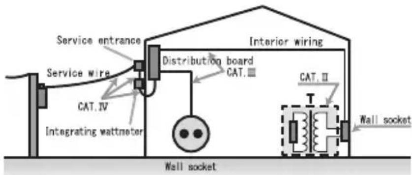
Measurement categories (Overvoltage categories)
CAT. II : Primary circuit of equipment with a power cord to be connected to a mains socket.
CAT.III: Primary circuit of equipment that inputs power directly from the distributor and the circuit from the distributor to the mains socket.
CAT.IV: Circuit from the leading wire to the distributor
[3] NAMES OF COMPONENT UNITS
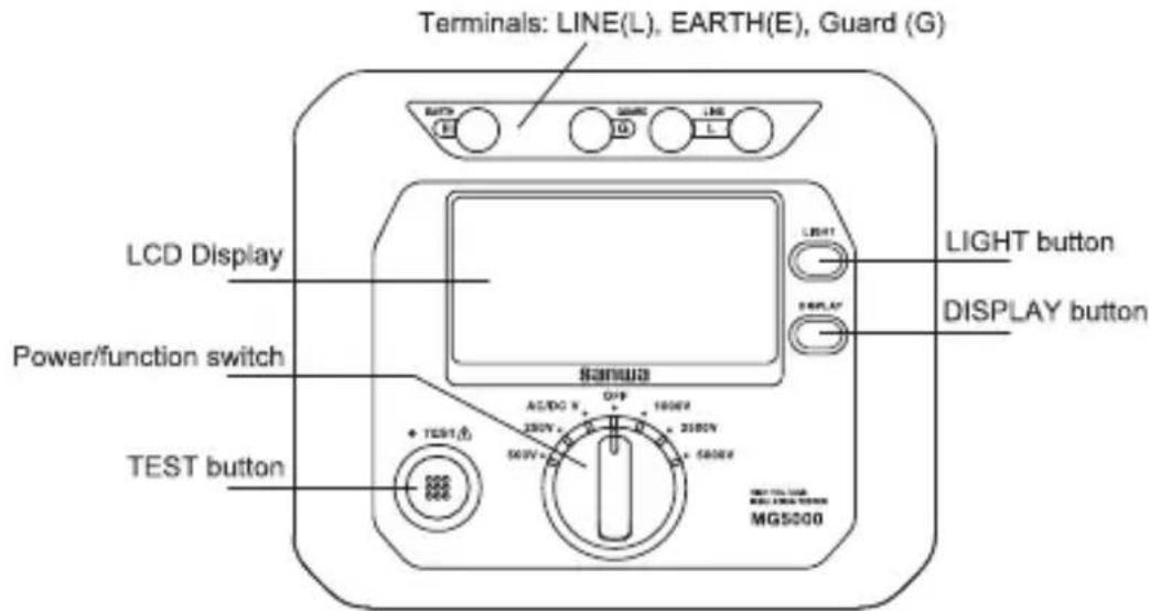
3-1 Main Unit
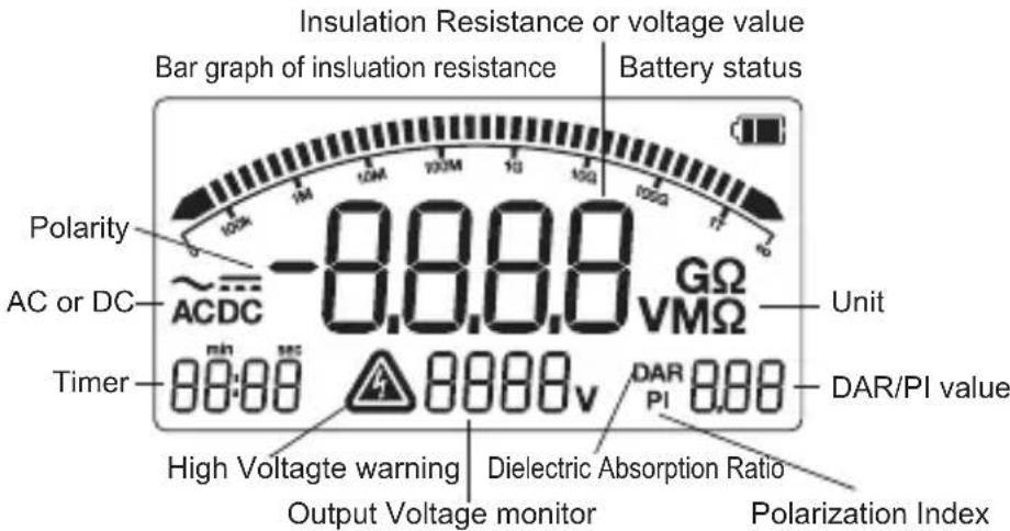
3-2 Display
3-3 Test Leads : TL-5K
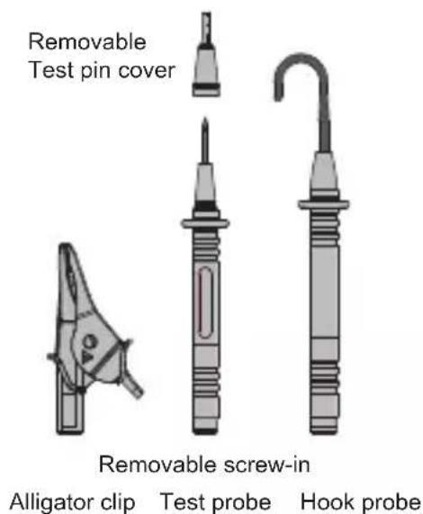
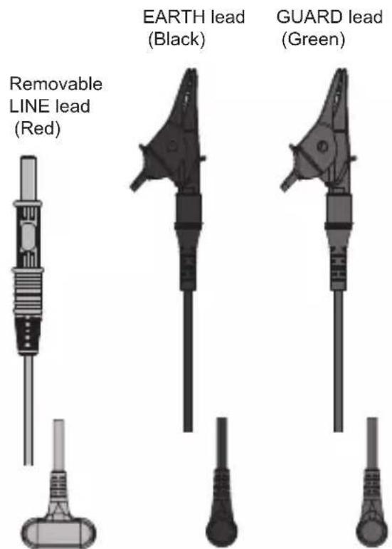
TL-5K-R : Removable LINE lead (Red) : 3 m
TL-5K-B : EARTH (ground) lead (Black) : 3 m
TL-5K-G : GUARD lead (Green) : 3 m
TL-5K-A : Alligator clip
TL-5K-P : Test probe (Removable test pin cover) Uncovered with the cover : CAT.II 1000 V Covered with the cover : CAT.IV 600 V/CAT.III 1000 V
TL-5K-H : Hook probe (No Measurement Category) Take special care against accidents caused by short-circuiting, etc.
3-4 Optional Accessories
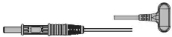
TL-5K-15 : Removable LINE lead (Red) : 15 m
Note : The period in which the insulation resistance is stable varies depending on the length and distribution method of the cable.
natural_image
Illustration of a medical or laboratory device with two types of connectors (no text or symbols)[4] DESCRIPTION OF FUNCTIONS
4-1 Power/Function Switch
Turn this switch to turn on and off the power and to switch the measuring functions.
4-2 Starting/Stopping Measurement : TEST button
Press and hold the TEST button for more than 2 seconds to start the insulation resistance measurement. Press and hold the button for more than 1 second to stop the measurement.
* The measurement of the AC/DC V functions is possible without using the TEST button.
4-3 Backlight function : LIGHT Button
Press the LIGHT button to turn the display backlight on. Press the button again to extinguish it. The backlight also goes off in 60 seconds after it is turned on.
4-4 DAR/PI Display Switching : DISPLAY Button
Press the DISPL AY button during or after measurement to switch the display between the DAR (Dielectric Absorption Ratio) and PI (Polarization Index) values. (See 5-5 DAR/PI Measurements for details.)
4-5 Auto Hold
When the insulation resistance measurement is stopped, the last displayed value is held automatically until the next time the TEST button is pressed.
* The Auto Hold display is also canceled when the function switch position is changed.
4-6 Auto Power Off
The Auto Power Off function turns the display and tester off automatically in about 10 minutes after the last operation. To return from this status, turn the power switch to OFF then to another position.
* The Auto Power Off function is defeated during measurement of insulation resistance.
* A small current flows inside the meter even in the Auto Power Off status. After measurement, always turn the function switch to the OFF position.
4-7 Battery Monitor
The indication of the Battery Monitor starts to change as the battery power is consumed. When the displayed symbols decrease, replace the batteries if you are going to begin measurement for a long period. The measurement accuracy is maintained even when the symbol, but the accuracy is no longer guaranteed when the single symbol 📄 starts to blink. For how to replace the batteries, see 6-4 Battery Replacement.
| 3 symbols 10.6 | |
| 2 symbols | 8.6 -10.5 V |
| 1 symbol | 7.6 - 8.5 V |
| 1 symbol BLINK 6.9-7.5 | V (No accuracy specified) |
| bAtt | 6.8 V or below |
[5] MEASUREMENT PROCEDURE
![Sanwa MG5000 - [5] MEASUREMENT PROCEDURE - 1](/content/2026/05/895300/images/94b6782235fd68f1e490e313ceb78fdce6a4bbea0f9f45dc284be296c942dba8.jpg)
WARNING
- Never measure voltage of electric circuits that exceed CAT.IV 600 V/CAT.III 1000 V
- Do not change the function switch position in the middle of measurement.
- Keep your fingers behind the finger guards of the test probe and the barrier of the alligator clip.
- After measurement, release the test leads from the object measured and set the function switch to the OFF position.

CAUTION
Correct measurement may not be performed when using the tester in a ferromagnetic/intense electric field such as a place near a transformer, high-current circuit or a radio, or when measuring a circuit containing a large amount of harmonics such as an inverter.
5-1 Start-up Inspection
Check the following items before starting the daily measurement work.
- Appearance check: Check the appearance of the tester to see if it is free from damage caused by falling, etc.
- Accessories: Check that the test leads are free from irregularities such as wire disconnection and crack.
- Batteries : Install the batteries before using the tester for the first time. If the Battery Monitor indicates a single blinking symbol ☐, replace the batteries with new ones.(see 6-4) * If nothing is displayed, the batteries may be exhausted totally.
- Also check that the meter and your hands are not moistened by water, etc.
5-2 Voltage Measurement : AC/DC V

WARNING
-
Never input signals exceeding the maximum rated input value (see 1-3).
-
Use test leads suitable for the measurement category of the object measured.
When the measurement categories differ between the main unit and test leads, the lower measurement category will be applied.
* Do not attempt to measure a voltage using the hook probe (TL-5K-H) because the large area of the metal-exposed part is dangerous.
This function is capable of distinguishing the input between an AC voltage (ACV) and DC voltage (DCV) automatically.
| Function | Measurement range | Accuracy Note | |
| ACV 30- | 1000 V | ±(3 %rdg+2 dgt) | Input over 1000 V causes “OL” to be displayed and the buzzer to beep. |
| DCV 30- | 1000 V | ±(3 %rdg+2 dgt) |
* The accuracy-guaranteed frequencies of ACV are 50/60 Hz.
Procedure :
① Connect the LINE lead (Red) and EARTH (ground) lead (Black).
② Set the function switch to AC/DC V.
③ Connect the test leads to the object measured.
④ Read the displayed value (there is no need of pressing the TEST button). In the DCV measurement, the “-” sign is displayed when the Red lead is connected to negative polarity.
Notes :
- When the input is absent or below 30 V, the display shows [Lo] in the main value area.
- When the input is 30 V or more, whether it is an AC voltage (ACV) or DC voltage (DCV) is distinguished and displayed automatically.
- In case ACV and DCV are superimposed, the distinction is based on the voltage with the higher peak value.
5-3 Insulation Resistance Measurement

WARNING
- Never apply voltage to the input terminals.
- Wear high voltage insulation gloves.
- Isolate the power supply to the object measured (circuit) and make sure no voltage is applied to it before measurement.
- Do not touch the object measured during measurement because the tester generates a high voltage.
- Connect the EARTH (ground) lead (Black) first and then the LINE lead (Red). When disconnecting the test leads, disconnect the LINE lead first.
- The tester and measured circuit are charged with high voltage during measurement. To avoid the risk of electric shock, discharge the high voltage from the object measured immediately after measurement (see 5-4).

CAUTION
- The measurement terminals of the tester generate a high voltage during insulation resistance measurement.
- Some objects measured have unstable insulation resistance, in which case their readings become also unstable. The measurement of a capacitive load may sometimes take a long time.
-
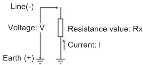
In the insulation resistance measurement, the EARTH (ground) terminal becomes “+” and the LINE terminal “-”.
-
When the object measured is grounded, usually connect the EARTH (ground) lead to the grounded side and the LINE lead to the circuit (the value read with this method is lower than that read with the reverse connection).
- To prevent measurement errors, keep the LINE cord away from the object measured and the ground whenever possible. Particularly, when measuring high resistance of 100 GΩ or more, the reading can be stabilized by keeping the test cord as apart as possible from each other.
- The insulation resistance varies widely depending on the temperature and humidity as well as on the test voltage. In general, it decreases as the temperature, humidity or voltage increases.
- The tester may generate a sound during voltage generation, particularly when the resistance is low. This is not malfunction.
| Nominal test voltage | Measurement range | Accuracy Note | |
| 250 V 0.0 | -104.9 MΩ | ±(5%rdg + 3 dgt) | OL at 105.0 MΩ or more |
| 500 V | 0.0-99.9 MΩ80-1049 MΩ | OL at 1050 MΩ or more | |
| 1000 V | 0.0-99.9 MΩ80-999 MΩ0.80-2.09 GΩ | OL at 2.10 GΩ or more | |
| 2500 V | 0.0-99.9 MΩ80-999 MΩ0.80-9.99 GΩ8.0-104.9 GΩ | OL at 105.0 GΩ or more | |
| 5000 V | 0.0-99.9 MΩ80-999 MΩ0.80-9.99 GΩ8.0-99.9 GΩ | OL at 1200 GΩ or more | |
| 80-1000 GΩ ±20%rdg | |||
| 1001-119 9 GΩ - |
Procedure :
Ensure that the measured circuit is turned OFF and that no voltage is present in it.
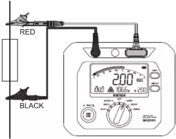
① Connect the EARTH (ground) lead (Black) to the EARTH (E)
terminal and the LINE lead (Red) to the LINE (L) terminal. Also connect the GUARD terminal if required.
(When using GUARD, also see 5-7 Using the GUARD Terminal.)
② Set the function switch to the desired test voltage function.
③ Connect the test leads to the object measured.
④ If a voltage of 30 V or more is present while the object is not measured, the high voltage warning is displayed and the buzzer beep is generated. In this case, the measurement cannot be started by pressing the TEST button. If this happens, check the power supply to the object measured.
⑤ Press and hold the TEST button for more than 2 seconds to start the voltage output. When the function uses a voltage of 1000 V or more, intermittent buzzer beeps are generated during measurement to warn about the high voltage generation.
⑥ Read the value or bar graph on the display.
⑦ To stop the measurement, press and hold the TEST button for more than 1 second. The value displayed at the moment the measurement is stopped is held automatically.
⑧ The object measured may be charged even after measurement. Ensure that it is free of voltage charge by referring to 5-4
Discharge Function and be sure to disconnect the LINE lead before the EARTH (ground) lead.
Example of insulation resistance measurement
Note :
- When the object measured is in the live status (≥30 V AC/DC), the display shows the voltage value together with ⚠ and a warning tone is generated. In this case, the test voltage is not output by pressing the TEST button. To start measurement, turn the power supply to the object measured OFF or discharge it.
- The batteries consume rapidly in measurement of resistance lower than rated test voltage x 0.001 MΩ for a long period. It is recommended to measure low resistances quickly in a short period. Example) Lower than 5 MΩ when the voltage is 5000 V, lower than 0.5 MΩ when it is 500 V.
- The maximum measurement period is 99 min. 59 seconds. The time display blinks when this limit is exceeded.
* Principles of insulation resistance measurement: The tester detects the current flowing through the object measured during application of DC voltage and calculates the resistance value with the following formula.
$$ \begin{array}{l} \text { Resistance value } = \text { Voltage / Current } \ (\mathrm{Rx} = \mathrm{V} / \mathrm{I}) \end{array} $$
5-4 Discharge Function
When the insulation resistance of a capacitive object is measured, it is charged by the test voltage. This function is provided to discharge the high voltage remaining in the object after measurement.
1) When stopping the insulation resistance measurement, keep the test leads connected to the object measured, and press and hold the TEST button for more than 1 second to turn off the power.
2) Discharging starts automatically. While the charge is discharged from the object measured, the display shows ⚠ together with the voltage value. ⚠ disappears when the discharge completes or the charge drops to 29 V or less.
5-5 DAR/PI Measurement
This function is used to check the increase over time of the insulation resistance after application of voltage to the object measured.
It automatically calculates and displays the DAR (Dielectric
Absorption Ratio), which is one of the insulation judgment criteria, as well as the PI (Polarization Index).
As the increase over time of the leak current of an insulator is affected by absorption of moisture, it is important for diagnosing insulation of cables. The time periods used to obtain the results are different between the DAR and PI.
5-5-1 DAR : Dielectric Absorption Ratio
The DAR refers to the ratio between the resistance values at 60 seconds and 30 or 15 seconds after the start of measurement. It is expressed with the following formula.
DAR = (Resistance at 60 sec. after voltage application)/(Resistance at 30 or 15 sec. after voltage application)
Changing between the 30 and 15 sec. settings
* The default period set at the factory is 15 sec.
1) With the power/function switch set to OFF, press and hold the DISPLAY button while turn the power/function switch to ON. The display shows "DAR" and "00:30" or "00:15" in the timer area at the bottom left of the panel.
2) Each press of the DISPLAY button alternates "00:30" and "00:15".
3) The time period displayed at the moment the power switch is set to OFF again is saved.
The current setting can be checked with the operation in step 1).
5-5-2 PI : Polarization Index
The PI refers to the ratio between the resistance values at 10 minutes and 1 minute after the start of measurement. It is expressed with the following formula.
PI = (Resistance at 10 min. after voltage application)/(Resistance at 1 min. after voltage application)
5-5-3 DAR/PI measurement procedure
The DAR and PI are measured automatically by the continual insulation resistance measurement. The DAR value is displayed in 1 minute after the start of measurement and the PI value in 10 minutes after.
Since the DAR and PI values are obtained by arithmetic operations, "no" is displayed when the calculation is impossible because the measurement is "0.0 MΩ" or "OL".
Example of display during DAR/PI measurement
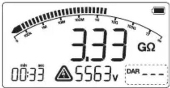
The display in the area inside the frame varies as follows.
“- - - ” is displayed for 1 minute after the start of measurement.
The DAR value is displayed in 1 minute.
The PI value is displayed in 10 minutes.
After 10 minutes, the DAR and PI values can be checked alternately by pressing the DISPLAY button.
Example of display after completion of measurement
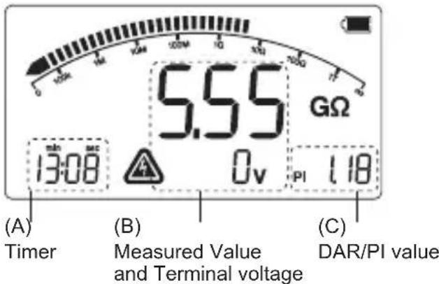
After completion of measurement, each press of the DISPLAY button can switch the four values, including the one at the completion of measurement, one at 15 or 30 seconds, one at 1 minute and one at 10 minutes after the start of measurement.
Each press of the button switches the displayed information as follows.
(1) Results at the completion of measurement :
(A) Time of completion of measurement.
(B) Value at completion of measurement.
(C) DAR or PI value.
(2) Results at 15 or 30 seconds after the start of measurement :
(A) 15 or 30 seconds.
(B) Value at 15 or 30 seconds after the start.
(C) DAR value.
(3) Results at 1 minute after the start of measurement :
(A) 1 minute.
(B) Value at 1 minute after the start.
(C) DAR value.
(4) Results at 10 minutes after the start of measurement:
(A) 10 minutes.
(B) Value at 10 minutes after the start.
(C) PI value.
(5) Returned to display (1).
* If the measurement time is insufficient, display (1) is returned by skipping other information.
5-6 Voltage Characteristics at Measuring Terminals
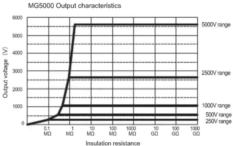
line
| Insulation resistance | Output voltage (V) | | --------------------- | ------------------ | | 0.1 MΩ | 0 | | 1 MΩ | 5700 | | 10 MΩ | 5700 | | 100 MΩ | 5700 | | 1000 MΩ | 5700 | | GΩ | 5700 | | 100 GΩ | 5700 | | 1000 GΩ | 5700 |* The batteries consume rapidly in measurement of resistance lower than rated test voltage/3 mA for a long period. It is recommended to measure low resistances quickly in a short period. (5000 V/1.8 MΩ, 2500 V/0.9 MΩ, 1000 V/0.36 MΩ, 500 V/0.18 MΩ, 250 V/0.0 9MΩ)
5-7 Using the GUARD Terminal
To use the GUARD terminal, connect the GUARD (Green) lead to the GUARD (G) terminal.
When measuring the insulation resistance of a cable, etc., wrap a bare conductor around the insulator surface and connect to the GUARD terminal. This makes it possible to prevent the insulation resistance measurement error that may be produced when the leak current on the surface flows into the current detection area.
Caution : Do not apply a voltage across the EARTH (ground) and GUARD terminals.
Insulation resistance tester
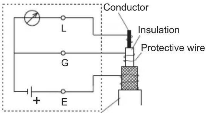
Cable with sheath
[6] MAINTENANCE
![Sanwa MG5000 - [6] MAINTENANCE - 1](/content/2026/05/895300/images/2ba4a079b48258b6d5323968fe1f5e51cb58ba24260947a6d32b63e5a72c5cf1.jpg)
WARNING
- This section is very important for safety. Read and understand the following instruction fully and maintain your instrument properly.
- The instrument must be calibrated and inspected at least once a year to maintain the safety and accuracy.
6-1 Maintenance and Inspection
1) Appearance:
• Is the appearance not damaged by falling?
2) Test leads, measurement probe and alligator clip:
- Is the cord of the test leads not damaged or the core wire not exposed at any place of the test leads?
• Is the measurement probe or alligator clip fit tightly?
If any of the above is found with the appearance, do not use the equipment and have it repaired or replaced.
6-2 Calibration
The calibration and inspection may be conducted by the dealer. For more information, please contact the dealer.
6-3 Cleaning and Storage

CAUTION
- The main unit is not resistant to volatile solvent and must not be cleaned with lacquer thinner or alcohol. If it gets dirty, wipe lightly with a soft cloth moistened with a small amount of water.
- The main unit is not resistant to heat. Do not place it near a source of high heat.
- Do not store the instrument in a place where it may be subjected to excessive vibrations or from where it may fall.
- For storing the instrument, avoid hot, cold or humid places or places under direct sunlight or where condensation is anticipated.
- When the instrument is not to be used for a long period, be sure to remove batteries from it.
Following the above instructions, store the instrument in good environment.
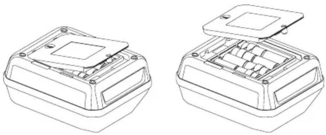
6-4 Battery Replacement

WARNING
-
If the battery lid is removed with input applied to the input terminals or in the middle of measurement, you may get electrical shock. Before starting the work, always make sure that no input is applied.
-
Before starting the work, ensure that the function switch is set to OFF.
natural_image
Technical line drawings of two electronic components with internal compartments and mounting holes (no text or symbols)① Using a Phillips screwdriver, turn the battery lid retaining screw (x 1) until it turns idle.
② Push the area marked PUSH to lift the battery lid and then remove it.
③ Replace the eight batteries by taking care of the polarity
④ Attach the battery lid and secure the retaining screw.
[7] AFTER-SALE SERVICE
7-1 Warranty and Provision
Sanwa offers comprehensive warranty services to its end-users and to its product resellers. Under Sanwa's general warranty policy, each instrument is warranted to be free from defects in workmanship or material under normal use for the period of one (1) year from the date of purchase.
This warranty policy is valid within the country of purchase only, and applied only to the product purchased from Sanwa authorized agent or distributor.
Sanwa reserves the right to inspect all warranty claims to determine the extent to which the warranty policy shall apply. This warranty shall not apply to disposables batteries, or any product or parts, which have been subject to one of the following causes:
- A failure due to improper handling or use that deviates from the instruction manual.
- A failure due to inadequate repair or modification by people other than Sanwa service personnel.
- A failure due to causes not attributable to this product such as fire, flood and other natural disaster.
- Non-operation due to a discharged battery.
- A failure or damage due to transportation, relocation or dropping after the purchase.
7-2 Repair
Customers are asked to provide the following information when requesting services :
- Customer name, address, and contact information
- Description of problem
- Description of product configuration
- Model Number
- Product Serial Number
- Proof of Date-of-Purchase
- Where you purchased the product
Please contact Sanwa authorized agent/distributor/service provider, listed in our website, in your country with above information. An instrument sent to Sanwa/agent/distributor without above information will be returned to the customer.
Note :
1) Prior to requesting repair, please check the following : Capacity of the built-in battery, polarity of installation and discontinuity of the test leads.
2) Repair during the warranty period : The failed meter will be repaired in accordance with the conditions stipulated in 7-1 Warranty and Provision.
3) Repair after the warranty period has expired :
- If it is expected that servicing can restore the original functioning of the instrument, we will service it for a price upon request of the user.
- The service charge or transport freight could sometimes become higher than the product price. Please consult us before asking for servicing.
- The minimum retention period of the servicing performance parts of this instrument is six (6) years after the discontinuation of production. This period is equal to the servicing available period. However, the retention period of a part may be reduced if it becomes unavailable due to discontinuation of production of the part manufacturer, etc.
4) Precautions when sending the product to be repaired: To ensure the safety of the product during transportation, place the product in a box that is larger than the product 5 times or more in volume and fill cushion materials fully and then clearly mark “Repair Product Enclosed” on the box surface. The cost of sending and returning the product shall be borne by the customer.
7-3 SANWA Website
http://www.sanwa-meter.co.jp
E-mail : exp_sales@sanwa-meter.co.jp
[8] SPECIFICATIONS
8-1 General Specifications
| AC sensing Average value | |
| LCD 1200 counts | Bar graph : 36 pointsDAR/PI value : 9.99Timer : 99 : 59 (min. : sec.) |
| Sampling rate Approx. | 3 times/sec. |
| Overload indication | V function : “OL” displayed with buzzer beepInsulation function : "OL" displayed |
| Range selection Auto | range only |
| Polarity switching | Auto switching (only “-” is displayed) |
| Battery Monitor 4-step | indication (see 4-7)blinks at about 7.5 V or less (accuracy no longer guaranteed) |
| Environmental condition | Altitude 2000 m or below, indoor use, pollution degree II |
| Operating temperature/humidity | 0-40 °C, max. relative humidity 85 % (no condensation) |
| Storage temperature/humidity | -10-60 °C, max. relative humidity 90 %, no condensation (with batteries removed)(Batteries should be removed before storage for a long period.) |
| Power supply “C | ” -size alkaline battery 1.5 V (LR14) x 8 |
| Auto Power Off Power | OFF in about 10 minutes after last operation. |
| Max. power consumption | Approx. 18 VA (measurement at 5000 V/ approx. 1.8 MΩ) |
| Measurement count | 1000 times (5000 V/5 MΩ measurement, 5 sec. ON/25 sec. OFF) |
| Dimensions & mass | 188(H) x 225(W) x 97(D) mm, approx. 1750 g (batteries included) |
| Year of production Initial 2 digits of the main unit serial No.indicates the last two digits of year (20**). | |
| IP class IP54 | |
| Safety standards | IEC61010-1 CAT.III 1000 V/IV 600 VIEC61010-2-030, IEC61010-031. IEC61557-1 & 2 |
| EMC Directive, RoHS Directive | IEC61326 (EMC). EN50581 (RoHS) |
| Accessories | Instruction manual, test leads (TL-5k)Red/Black/Green, carrying case (C-MG5k), “C”-size alkaline batteries x 8 |
| TL-5k contents | TL-5K-R : 3 m LINE lead (Red) Removable typeTL-5K-B : 3 m EARTH (ground) lead (Black)TL-5K-G : 3 m GUARD lead (Green)TL-5K-A : Alligator clipTL-5K-P : Test probeTL-5K-H : Hook probe |
| Optional accessory | TL-5K-15 : 15 m LINE lead (Red), Removable type |
Current consumption (typical value at 12 V of supply voltage)
| Function | 250 V 5 | 00 V 100 | 0 V 2500 | V 5000 V | AC/DC V | |
| Output at short-circuit | 450 mA | 45 mA | ||||
| Output at rated current | 750 mA /0.09 MΩ | 500 mA /0.18 MΩ | 700 mA /0.36 MΩ | 1200 mA /0.9 MΩ | 1500 mA /1.8 MΩ | |
| Output at open-circuit | 10 mA 1 | 0 mA 30 | mA 50 mA | 100 mA | ||
| Stand-by | 45 mA | |||||
| Backlight on | 60 mA increases | |||||
Continuous operation time : Approx. 25 hours with 5000 V function and 100 MΩ load.
8-2 Measuring Ranges and Accuracies
Accuracy-guaranteed temperature/humidity ranges: 23 ±5 °C, no more than 80 %RH (without condensation)
rdg : Reading. dgt : Lowest digit.
ACV/DCV
| Measurement range Resolution Accuracy | |
| 30-1000 V (50/60 Hz) | 1 V ±(2.0 %rdg + 3 dgt) |
| ±30-±1000 V DC | |
Accuracy-guaranteed frequencies : 50/60 Hz, input impedance approx. 100 MΩ
Insulation resistance
* Accuracies of the main unit excluding the effects of test leads on measurements.
| Rated output voltage | 250 V 5 | 00 V 1000 | V 2500 V | 5000 V | ||
| Measuring Range | 0.0-104.9 MΩ | 0.0-99.9 MΩ80-1049 MΩ | 0.0-99.9 MΩ80-999 MΩ0.80-2.09 GΩ | 0.0-99.9 MΩ80-999 MΩ0.80-9.99 GΩ8.0-104.9 GΩ | 0.0-99.9 MΩ80-999 MΩ0.80-9.99 GΩ8.0-99.9 GΩ | 80-1000 GΩ(No accuracy 10 01-1199 G) |
| Accuracy | ±(5 %rdg + 3 dgt) ±20 % | |||||
| Open-circuit voltage | DC 250 V0 %-+20 % | DC 500 V0 %-+20 % | DC 1000 V0 %-+20 % | DC 2500 V0 %-+20 % | DC 5000 V0 %-+20 % | |
| Rated current | 3 mA ±0.5 mA | |||||
| Short-circuit current | 3 mA-4 mA | |||||
Terminal voltage display (Output Voltage monitor)
| Measurement range | Resolution Accuracy | |
| 30-6000 V 1 V ± | (5 %rdg + 10 dgt) | |
| Note: In the insulation resistance measurement, the voltage used in measuring resistances lower than 5000 V/1.8 MΩ, 2500 V/0.9 MΩ, 1000 V/0.36 MΩ, 500 V/0.18 MΩ or 250 V/0.09 MΩ is out of the accuracy-guaranteed range and handled as a reference value. | ||
This display makes it possible to check the voltage output from the output terminal or the discharge status of the charge accumulated in the object measured.
To measure the voltage, use the AC/DC V function.
Accuracy calculation method
Example) ACV (AC voltage) measurement
Displayed value : 500 V
Range and accuracy : ±(2.0 %rdg + 3 dgt) in 1000 V range
Error : ±(500 V x 2.0 % + 3 dgt) = ±13 V
True value : 500 V ±13 V (487 to 513 V)
* In the 1000 V range, the 3 dgt corresponds to 3 V.
The product specifications described in this manual and its appearance are subject to change without notice for improvement or other reasons.
MEMO
sanwa®
三和電気計器株式会社
- [1] SAFETY PRECAUTIONS -Before use, read the following safety precautions.-
- [2] APPLICATIONS AND FEATURES
- [3] NAMES OF COMPONENT UNITS
- [4] DESCRIPTION OF FUNCTIONS
- [5] MEASURING PROCEDURE
- [6] MAINTÉNANCE
- [7] AFTER-SALE SERVICE
- [8] SPECIFICATIONS
- [1] SAFETY PRECAUTIONS
- 1-1 Explanation of Warning Symbols
- 1-2 Warning Instruction for Safe Use
- WARNING
- 1-3 Overload Protection Input Values
- 2-1 Applications
- 2-2 Features
- Measurement categories (Overvoltage categories)
- 3-1 Main Unit
- 3-2 Display
- 3-3 Test Leads : TL-5K
- 3-4 Optional Accessories
- 4-1 Power/Function Switch
- 4-2 Starting/Stopping Measurement : TEST button
- 4-3 Backlight function : LIGHT Button
- 4-4 DAR/PI Display Switching : DISPLAY Button
- 4-5 Auto Hold
- 4-6 Auto Power Off
- 4-7 Battery Monitor
- [5] MEASUREMENT PROCEDURE
- CAUTION
- 5-1 Start-up Inspection
- 5-2 Voltage Measurement : AC/DC V
- Procedure :
- Notes :
- 5-3 Insulation Resistance Measurement
- Note :
- 5-4 Discharge Function
- 5-5 DAR/PI Measurement
- 5-5-1 DAR : Dielectric Absorption Ratio
- Changing between the 30 and 15 sec. settings
- 5-5-2 PI : Polarization Index
- 5-5-3 DAR/PI measurement procedure
- Example of display during DAR/PI measurement
- Example of display after completion of measurement
- 5-6 Voltage Characteristics at Measuring Terminals
- 5-7 Using the GUARD Terminal
- [6] MAINTENANCE
- 6-1 Maintenance and Inspection
- 6-2 Calibration
- 6-3 Cleaning and Storage
- 6-4 Battery Replacement
- 7-1 Warranty and Provision
- 7-2 Repair
- 7-3 SANWA Website
- 8-2 Measuring Ranges and Accuracies
- Insulation resistance
- Accuracy calculation method
- sanwa®
- 三和電気計器株式会社
Brand : Sanwa
Model : MG5000
Category : Measurement