
Bullfrog - Keyboard Erica Synths - Free user manual and instructions
Find the device manual for free Bullfrog Erica Synths in PDF.


| Product Type | Semi-modular synthesizer |
| Brand | Erica Synths |
| Model | Bullfrog |
| Design | Fully analogue |
| Power Supply | 12 VDC wall wart adapter (included) |
| Voltage Controlled Oscillator (VCO) | Sine and pulse waveforms, frequency range 20 Hz – 10 kHz, 1V/oct tracking over 8 octaves |
| VCO Wave Shaping | Sine to sharkfin, pulse width modulation (10% – 90%) |
| Noise Generator | Zener diode-based white noise |
| Mixer | Level controls for sine, pulse, noise; external inputs (IN1–3); mix output |
| Voltage Controlled Filter (VCF) | 24 dB/oct lowpass resonant filter, self-oscillating, 1V/oct tracking |
| Voltage Controlled Amplifier (VCA) | Adjustable offset, built-in delay effect (30 ms – 340 ms) |
| Envelope Generators | Two looping attack-sustain-release (ASR) generators, unipolar (0–5V) and bipolar outputs |
| Sample & Hold | Internal clock, free-running or gated mode |
| Divider | Frequency division by 2, 4, 8, 16 |
| Voice Card Slot | Expandable via optional voice cards (Acid Bassline, Sampler/Looper, Sequencer, etc.) |
| MIDI Interface | DIN5 MIDI input, USB-C MIDI input |
| Built-in Speaker | Yes |
| Included Accessories | 10 patch cables, 3 pre-patched voice cards, 3 DIY voice cards, user manual |
| Operating Temperature | -20°C to +50°C |
| Safety | Use only supplied PSU; avoid humidity; transport in original packaging |
Frequently Asked Questions - Bullfrog Erica Synths
User questions about Bullfrog Erica Synths
0 question about this device. Answer the ones you know or ask your own.
Ask a new question about this device
Download the instructions for your Keyboard in PDF format for free! Find your manual Bullfrog - Erica Synths and take your electronic device back in hand. On this page are published all the documents necessary for the use of your device. Bullfrog by Erica Synths.
USER MANUAL Bullfrog Erica Synths

user manual

2 Introduction and connections
5 a short introduction into sound physics
6 what is a sound
7 a pitch
9 amplitude or volume
10 timbre
11 waveforms
13 overtones and harmonics
16 subtractive synthesis and subtractive synthesizers
17 subtractive synthesis
18 filters
21 amplifiers
22 voltage control
23 subtractive synthesizer
25 how the bullfrog works
27 voltage controlled oscillator (vco)
28 noise generator and mixer
36 voltage controlled filter (vcf)
41 voltage controlled amplifier (vca)
45 control voltage (cv) sources
46 envelope generators
57 sample & hold
64 divider
69 voicecards
73 midi implementation and configuration
74 patch notes
84 safety instructions
disposal84
thank you for purchasing erica synths x richie hawtin bullfrog synthesizer!

Electronic music with its rich traditions and innate sense of exploration at core is ever popular, with artists and fans stretching around the globe. For me, one of the most exciting parts of creating electronic music is the playful exploration that leads one deep into their own imagination. Whether the intention to create completely imagined or real-life inspired sounds, the route one takes to create is always personal and often surprising. It is within these experiments where the beauty of synthesis really comes alive and which often unlocks a new sense of creativity and purpose. This journey of discovery is what originally pulled me deep into the world of electronic music and continues to be part of the fascination I find when working in the studio or performing on stage. Early on I felt that I was a kid looking for the right outlet for me in order to fully understand and transmit my creativity. These memories and concepts are at the heart of our Bullfrog synthesizer. Whether someone's experience with Bullfrog points them down a career in electronic music or not, our goal is to both nurture the love for electronically produced sounds and promote the accessibility of learning and understanding the basics of sound synthesis.
We believe that the hands-on approach and problem solving that is innate to synthesis on a semi-modular synth like the Bullfrog, contains life lessons that go beyond what we can hear.
Bullfrog encapsulates the foundations of synthesis and is built with an immediate, intuitive design and a unique expandable architecture that grows and expands together with our user's imagination. This instrument feels at home anywhere - as an educational tool in music and physics classes, as an addition to your basement studio or even as a tool for performance on a stage.
- Richie Hawtin
For most up to date content, video tutorials and learning resources, please, visit www.bullfrog.ericasynths.lv
features
▶ Fully analogue design
▶ Highly accurate voltage controlled oscillator (VCO) that tracks great over 8 octaves
- Manually adjustable and voltage controlled waveshapes – sine-shark fin and pulse wave with pulse width modulation (PWM)
▶ Zener diode-based noise generator
▶ Resonant lowpass voltage controlled filter (VCF)
▶ Voltage controlled amplifier (VCA) with adjustable offset
▶ Delay effect with adjustable delay time and feedback amount
▶ Two looping attack-sustain-release envelope generators (EG)
▶ Sample & Hold circuit with an individual clock
▶ Manual gate button
▶ Voicecard slot
▶ Built in speaker
▶ DIN5 MIDI input
USB connector
what's included
BULLFROG synthesizer
▶ Universal 12VDC wall wart adapter
▶ User manual
10 patch cables
3 pre-patched voice cards
3 DIY voice cards

a short introduction into sound physics

what is a sound
Before we start exploring the Bullfrog as a tool for sound synthesis, let's look at some basic concepts behind the sound itself.
What is a sound? In physics, sound is a vibration that propagates as an acoustic wave through a transmission medium such as a gas, liquid or solid. But this does not mean that a human can perceive all such mechanical vibrations. In human psychology, sound is the reception of such waves and their perception by the brain.
How do these vibrations and acoustic waves occur and how can we generate them in a controlled way? The easiest way is to examine how a speaker works. When a speaker is connected to an oscillating electrical voltage source, it initiates the motion of the speaker membrane.
When the voltage increases, the membrane cone of the speaker is pushed outwards and it pushes air molecules forward, thus forcing them together and creating a high pressure (HP) area (see Figure 1).
Likewise, when the voltage decreases, the membrane is pulled inwards and it causes air molecules to thin out as it creates a low pressure (LP) area.
These high and low pressure areas travel through the air as an acoustic wave until they reach our ears and the sophisticated structures in our ears and brains interpret these pressure changes as sound.

a pitch
The speed of the membrane vibration will determine the pitch of the sound. If the membrane is pushed out and pulled in 55 times per second, we hear very low-pitched sound.
In physics, the amount of vibrations per second is called frequency, and it has a measurement unit - hertz (Hz). So, if the membrane vibrates 55 times a second, the frequency is 55 Hz. In music, frequency is commonly called a pitch. You can see a standard 8 octave piano keyboard with corresponding frequencies in Figure 2.
Only acoustic waves that have frequencies in the range between about 20 Hz and 20 000 Hz (or 20 kilohertz (kHz) – similarly to meters and kilometers) are within the audible frequency range that can be perceived by humans and interpreted as sound. When you are younger, your hearing range is greater, but it reduces with age. Sound waves above 20 kHz are known as ultrasound and are not audible to humans. Sound waves below 20 Hz are known as infrasound.
Different animal species have varying hearing ranges that go well below or above ours.
All synthesizers, including the Bullfrog, have electrical circuits that generate oscillating electrical signals that are sent to speakers, and these speakers turn them into sound waves. The Bullfrog synthesizer can generate sounds with frequencies between 20 Hz to 10 kHz – this is well beyond range of a piano (see Figure 3).
0 20 20,000 40,000 160,000 Frequency Hz
Infrasounds Human auditory field Ultrasounds

Figure 3
A SHORT INTRODUCTION INTO SOUND PHYSICS
Pay attention to relations of frequencies on the piano keyboard! Modern keyboards use an equally-tempered scale - a musical temperament or tuning system, which approximates note intervals by dividing an octave into equal steps, in our case, 12 semitones. This means that the ratio of the frequencies of any adjacent pair of notes is the same, which gives an equal perceived step size.
It becomes even more interesting if we compare frequencies of the same notes in different octaves.
A1 has a frequency of 55 Hz (as we figured out before - this means that the membrane of the loudspeaker or a piano string representing A1 vibrates 55 times per second), A2 is 110 Hz, A3 is 220 Hz, A4 is 440 Hz, A5 is 880 Hz, etc. – we get frequency of a note in the next octave by multiplying the frequency of the note of the previous octave by 2 – A4 = A3x2.
Remember these relations because they will explain why different instruments have different "flavor" of sound.

Figure 2
A SHORT INTRODUCTION INTO SOUND PHYSICS
amplitude or volume
You may have noticed that the same sound from the same loudspeaker can be played quiet or loud depending on the volume setting. What does this mean in practical terms?
When no signal is applied to a loudspeaker, the loudspeaker cone is at rest – in the center position. When an oscillating voltage is applied to the loudspeaker, its cone starts deviating from the center thus creating high and low pressure areas in the air (Figure 4). If those deviations are small, you hear a quiet sound, but as the deviations increase, the sound gets louder. The amount of maximum deviation from the center of the loudspeaker cone is called the amplitude.
The volume control on a synthesizer or a mixing desk determines the amplitude of the electrical signal delivered to the speaker. The greater the amplitude of the electrical signal delivered to the speaker, the louder the sound coming from the speaker. In the figure 5 below you can see electrical oscillations with the same frequency but different amplitudes. The volume of the sound increases from the left to the right, as the amplitude of the electrical signal increases.
So, we might say that the volume control on the synthesizer is actually an amplitude control since it really controls the amplitude of the electrical signal going into the speaker.

Figure 5
timbre
When you listen to different musical instruments, even when they produce a sound of the same pitch and the same volume, you will notice a different "flavor" or "colour" of the sound each instrument produces.
For example, a flute sounds very pure and simple, while a clarinet produces a bright, but "hollow" sound. In music, these differences are called timbre.
There's a device called an oscilloscope (Figure 6) that "visualizes" the sound. If you connect a microphone to the oscilloscope and play an instrument, the microphone will do the opposite of what a speaker does – it will turn the sound waves into electrical oscillations, and the oscilloscope will show, how the sound from the specific instrument "looks" (Figure 7). One of the optional voice cards that will be available for the Bullfrog features a small oscilloscope, and you can observe the different waveforms yourself.

Figure 6
waveforms
As you can see, each instrument produces signals with different shapes and these shapes in synthesizer terms are called waveforms. If we record these signals and play them back, the loudspeaker will reproduce them in exactly the same way - you will recognize a clarinet or flute playing. This means that the motion of the membrane of the loudspeaker "copies" the waveform.
In the case of the sound of a clarinet, the loudspeaker will make rapid movement in and out because of steep rising and falling edges of the waveform, while for a flute it will move more gradually and produce a more “gentle” sound.
There are various ways in which synthesizers can generate sound, but for the sake of simplicity we will focus mostly on subtractive synthesis, which is also how the Bullfrog works.
Synthesizers have Oscillators that most commonly produce basic waveforms (see Figure 7) that are afterwards treated in various ways.
Please note that changing the frequency or amplitude of a wave will not change its shape (Figure 8).

Sine wave
A pure, flute-like
sound

Sawtooth wave
A bright, flull,
brassy sound

Square wave
A bright, but hollow
sound much like a
clarinets

Pulse wave
A nasal, "reedy"
sound
Sawtooth waveform of various frequencies


Sinewave of various amplitudes


Low volume Moderate volume High volume
Figure 7 Figure 8
A SHORT INTRODUCTION INTO SOUND PHYSICS
waveforms
There is more to waveforms – they can be periodic and aperiodic. Periodic waveforms have a repeating pattern - if we take the smallest unique part of the waveform – a cycle – you can see that neighboring cycles are exactly the same. The shape of these waveforms could probably slightly change over a longer period of time, but a repeating pattern will still be there.
A repeating pattern ensures constant pitch, therefore most musical sounds have a periodic waveform (Figure 9).
But not all waveforms are periodic. Some waveforms are so complex that there is no repeating pattern and such waveforms are called aperiodic. Sounds with aperiodic waveforms have no pitch. Noise, thunder, wind, rain are sounds with aperiodic waveforms, and they are an equally important ingredient in sound synthesis (Figure 10).
Periodic waveforms

Figure 9 Figure 10
Aperiodic waveforms

Based on what we've learned, we can summarize the following relationships:
Perceived subjective changes in: Correspond to physical changes in:
| Pitch | Frequency |
| Volume | Amplitude |
| Timbre | Waveform |
This is worth remembering because synthesizers work with the qualities listed in the right column, while perceived results are changes in the subjective qualities in the left column.
overtones and harmonics
The overtones are typically pure sounds (sine waves), but with a lesser amplitude. In music, overtones that are simple multiples of the fundamental are called harmonics.
Now, let's dig a little deeper and figure out why different waveforms produce different sounds! Let's take a closer look at a piano string when it's hit by a hammer (Figure 11)! If it's A2, then the string will vibrate at 110Hz or 110 times per second and you will hear low pitched sound.
But there are also other vibrations that take place in the string – the most prominent is the main vibration of the whole string at 110 Hz, and it's called a fundamental, but simultaneously there are secondary vibrations called overtones when waves are formed through points that divide the string in 2, 3, 4, 5, etc. parts. Those secondary vibrations will produce higher-pitched sound and we can easily calculate the frequencies of the secondary vibrations. In our case, these are 110x2=220 Hz (which is A2 – one octave up), 110x3=330 Hz, 110x4=440 Hz (which is A4 – two octaves up), 110x5=550Hz, etc.
The resulting sound is more complex waveform, a sum of all vibrations.

Figure 11
A SHORT INTRODUCTION INTO SOUND PHYSICS
overtones and harmonics
Furthermore, in 1822, a French mathematician named Fourier claimed that any function (in our case waveform) can be expanded into a series of sinewaves of different amplitudes. Again - the relationship between amplitudes of harmonics determines the shape of the resulting waveform.
A SHORT INTRODUCTION INTO SOUND PHYSICS
There are advanced formulas in mathematics that allow for calculating specific frequencies of harmonics and their amplitudes. In Figure 12, the bars represent harmonics (multiplications of fundamental frequency f) and height of these bars represents the amplitude of specific harmonics.
Stated another way, complex waveforms can be created by adding together a number of sinewaves at specific amplitudes, and this is method of creating sounds is called additive synthesis. There are some synthesizers that work with additive synthesis.
Virtually all musical instruments produce complex sounds consisting of a main sound – the fundamental - and a set of overtones and it is the relative amplitude of different harmonics that allows us to distinguish between different instruments playing the same pitch (Figure 13). For example, string instruments and wind instruments with reeds produce sounds with are relatively rich in harmonics, while flutes and French horns produce sounds with relatively few harmonics.


Figure 12

Sine wave Sawtooth wave Triangle wave Square wave
Figure 13
test yourself a short introduction into sound physics
If you use a tape recorder to record a clarinet playing an A4 (440Hz) and then slow down the tape to half speed, what would the pitch be and would the waveform shape change?
2 Are following sounds periodic or aperiodic waveforms:
car horn,
- striking a garbage-can lid,
- rustling a piece of paper,
- a squeaky door hinge?
3 If the waveform repeats itself once every 1/100 of second, what is the frequency of the waveform?
4 If the sound gets so low in pitch that you can no longer hear it, is there still sound? How low do humans can hear pitch?
5 What is relationship between timbre and harmonics?
6 If you change the harmonics in a sound, will the timbre change? Will the waveform change?
7 Which instrument has harmonically richer waveform - violin of flute?
8 What is meant by additive synthesis?
Find the correct answers and explanations on www.bullfrog.ericasynths.lv
subtractive synthesis and subtractive synthesizers
subtractive synthesis
Subtractive synthesis is perhaps the most common synthesis method. It originated in 1960s when the first synthesizers were designed. As we saw in the previous chapter, complex waveforms can be created by adding a number of sinewaves together. The basic idea of subtractive synthesis is to do the opposite – to simplify a complex wave generated by the Oscillator by filtering out certain frequencies until you get the desired sound. This is where the Filter comes in – it's main role in the synthesizer is to alter the timbre of the sound.
The Bullfrog features a voltage-controlled lowpass filter (VCF) which selectively removes higher harmonics from a waveform, altering its spectral content. The main control on a filter is the "CUTOFF FREQUENCY" which sets the point where the filter starts blocking higher harmonics and as result it makes waves sound darker or "muddier". Figure 14 shows how the lowpass filter affects the square wave by removing higher frequencies until only the fundamental frequency sinewave remains.
If you continue decreasing the cutoff frequency, even the fundamental sinewave will eventually be attenuated (it's amplitude will decrease) and ultimately, there will be no sound on the output of the filter, which means that the filter is completely closed. Obviously, a filter wouldn't do much to alter the sound of a sine wave except reducing its amplitude since it contains no harmonics. For harmonic-rich waves, however, such as square, triangle and sawtooth waves it makes quite a bit of difference.

Figure 14
SUBTRACTIVE SYNTHESIS AND SUBTRACTIVE SYNTHESIZERS
filters
In the example above we saw an idealized lowpass filter – it cuts off higher harmonics sharply above the cutoff frequency. In real life electronics and music applications, however, such filters do not exist – there is a certain "rolloff" tail of the filter (Figure 15).
The slope of the filter determines how effectively it blocks higher harmonics and it is measured in decibels per octave (dB/oct). In synthesizers, the most common slopes are 12 dB/oct, 18 dB/oct and 24 dB/oct. The higher the number, the steeper the slope and the better it's ability to block higher harmonics and to "smoothen" the sound. The Bullfrog features a 24 dB/oct voltage-controlled lowpass filter.
Most synthesizer filters have an additional characteristic with an associated control on the panel called RESONANCE. Adding resonance to the lowpass filter causes the filter to emphasize the band of frequencies just at the cutoff point (Figure 16). Almost every mechanical instrument has its own characteristic resonances, and in order to simulate natural sounds, the synthesizer must be able to simulate these resonances.
For instance, when you talk through a long pipe, you will notice that your voice is muffled because the pipe acts as a lowpass filter, but your voice also has a kind of nasal quality, which is characteristic of resonance. A pillow would be an example of a lowpass filter without resonance – your voice is simply muffled by the pillow. On synthesizers, increasing the resonance on a lowpass filter initially causes the addition of some specific harmonics to the sound, but when resonance is pushed to the extreme, the filter starts to self-oscillate – it generates a sinewave of a certain frequency that is added to the sound that passes through the filter.
But there is more about filters and their applications in synthesizers.

Figure 15

Figure 16
As we saw above, the LOWPASS filter passes all frequencies BELOW a certain cutoff frequency (Figure 17).
The HIGHPASS filter does the opposite – it passes all frequencies ABOVE the filter cutoff frequency (Figure 18).
There are several other specific filter types that are sometimes used in synthesizers, like the BAND REJECT or NOTCH filter, which is opposite to the bandpass filter – it passes all frequencies EXCEPT a certain band of frequencies (Figure 19).

Figure 17

Figure 18

Figure 19
SUBTRACTIVE SYNTHESIS AND SUBTRACTIVE SYNTHESIZERS
filters
When you connect highpass and lowpass filters in series (Figure 20), each filter will do its job and as a result, we have a BANDPASS filter – it passes only a certain band of frequencies, eliminating frequencies both ABOVE and BELOW the band being passed (Figure 21). Typical controls on bandpass filters are center frequency (the frequency of the peak of the bell-shaped band) and bandwidth (how wide the bell-shape is and therefore – how much sound is passed through).
By manipulating highpass and lowpass filter settings, you can achieve different results on the bandpass filter (Figure 22, Figure 23). Bandpass and lowpass filters are most useful in sound design and the bodies of most acoustic instruments (the tubing and bell of a trumpet, the wooden resonator of a violin) are effectively lowpass or bandpass filters. The Bullfrog has an optional accessory – a HIGHPASS FILTER voicecard that allows for experimenting with different filters.

Figure 20

Figure 21

Figure 22

Figure 23
amplifiers
So far, we have explored waveform generation at specific pitch (Oscillator), timbre manipulation by the Filter, but we have one more parameter of sound to look at – amplitude or volume. For this purpose, synthesizers have voltage-controlled amplifiers.
As the name suggests, a voltage-controlled amplifier (VCA) changes the amplitude of a signal – it basically works as an automated volume control on your audio system, laptop or smartphone. It can totally silence the signal by bringing its amplitude to zero, gradually increase it or pass the signal through unaltered, depending on what control signals it receives (Figure 24).

Silence Low volume Moderate volume High volume
Figure 24
SUBTRACTIVE SYNTHESIS AND SUBTRACTIVE SYNTHESIZERS
voltage control
This brings us to the concept of Voltage Control. See, all synthesizers have manual controls over parameters, meaning you can tweak a knob that changes the pitch of the oscillator, for example, or change timbre of the sound by manipulating the cutoff knob on the filter and alter the volume of the sound by tweaking the relevant knob on the amplifier.
But because you only have two hands and there are so many parameters to tweak, some genius engineers (most recognized pioneers in this field were Bob Moog and Don Buchla, who came up with their own concepts of synthesizers independently) in the 1960s introduced automated controls over most parameters on a synthesizer. They developed Voltage Controlled Oscillators, Voltage Controlled Filters and Voltage Controlled Amplifiers – all these “components” of the synthesizer can be controlled not only manually, but also automatically by applying certain voltages (Control Voltage or CV) to the dedicated control inputs (Figure 25).
For this purpose, they also developed numerous control voltage sources – Low Frequency Oscillators, Envelope Generators, Sample and Hold units, sequencers and keyboards. Yes, a keyboard on a synthesizer is a control voltage source that, by depressing a key, generates a certain voltage that sets the pitch of an oscillator.
We will explain how control voltage sources work and how they interact with signal generation and treatment sources later in this manual.
![graph TD A["Voltage Controlled Oscillator"] --> B["CONTROL VOLTAGE SOURCE"] B --> C["Waveform Input"] style A fill:#f9f,stroke:#333 style B fill:#ccf,stroke:#333 style C fill:#dfd,stroke:#333](/content/2026/05/895006/images/962bfbf02b6b83827e993482865da74f4fcaa886c4e444e2a54e81f73b8cbe4e.jpg)
Figure 25
subtractive synthesizer
Now we can use these building blocks to design a basic subtractive synthesizer (Figure 26)!
We have signal sources - the Voltage Controlled Oscillator (VCO) that outputs several waveforms, the pitch of which can be controlled by a keyboard or any other control voltage source, and a noise generator. Signals from both sources are sent to the mixer that defines the amplitude of each signal. The resulting signal is sent to the Voltage Controlled Filter (VCF) that alters the timbre of the signal. The timbre can be altered manually or by control voltage that, in this case, is generated by the Envelope Generator. The signal then goes to the Voltage Controlled Amplifier (VCA) that alters the amplitude of the signal; the second Envelope Generator sends a control voltage to the VCA.
The signal from the Voltage Controlled Amplifier now goes to the loudspeaker that turns the electrical signals from the synthesizer into sound.
Apart from Envelope Generators, there are other control voltage (CV) sources, found on synthesizers - Low Frequency Oscillators, Sample & Hold modules, Sequencers, Arpeggiators and many others.
Please note, that inside a synthesizer we have electrical signals only! The are sinewave or pulse-wave oscillations that are treated by all “modules” of the synthesizer, but they only turn into sound when they are sent to the loudspeaker or headphones. They turn electrical signals into sound by vibrating a membrane and creating sound waves in the air.
![graph TD A["VOLTAGE CONTROLLED OSCILLATOR"] --> B["MIXER"] C["NOISE GENERATOR"] --> B B --> D["VOLTAGE CONTROLLED FILTER"] D --> E["VOLTAGE CONTROLLED AMPLIFIER"] E --> F["Speaker"] G["ENVELOPE GENERATOR"] --> D H["ENVELOPE GENERATOR"] --> E](/content/2026/05/895006/images/f748508660b89b04b1c2e2883011600af961757db15592a7716e5cd09c42317c.jpg)
Figure 26
SUBTRACTIVE SYNTHESIS AND SUBTRACTIVE SYNTHESIZERS
test yourself subtractive synthesis and subtractive synthesizers
QUESTIONS
1 Describe the process of subtractive synthesis.
2 When you talk through the pillow, your voice becomes muffled. Do you think the pillow is a filter? What kind of filter it is?
3 What kind of controls a typical filter on a synthesizer has?
4 Describe differences between highpass and lowpass filters.
5 What is bandpass filter?
6 What filters are most used in sinthesizers?
7 Explain the concept of "voltage control". How can voltage control be more effective than manual control.
8 What's a role of voltage controlled amplifier in a synthesizer?
Find the correct answers and explanations on www.bullfrog.ericasynths.lv
how the bullfrog works

The Bullfrog is a classical subtractive synthesizer – it consists of several "modules" for sound generation – VCO, NOISE GENERATOR - and treatment – VCF, VCA/DELAY, as well as "modules" that generate control and modulation signals to control them – ENVELOPE GENERATORS and SAMPLE&HOLD. The Bullfrog will not make the sound on its own unless you make patches – use patch cables to interconnect the "modules" or insert voice cards that create internal connections between the "modules" in a specific way. This approach better helps to understand functionality of a subtractive synthesizer and the principles of sound design with instruments like these:
In order to fully understand the functionality of this synthesizer, let's take a closer look at the individual "modules" and let's try them in action!
HOW THE BULLFROG WORKS

voltage controlled oscillator (vco)
The Voltage Controlled Oscillator on the Bullfrog is an audio rate oscillator, that generates sine waves and pulse waves at frequencies that cover almost the entire audible range - from 20Hz to 10kHz (Figure 27).
The TUNE knob allows for manual adjustment of frequency and as the name suggests, the oscillator also has voltage control over the frequency.
The IV/oct input can be used to connect an external CV (control voltage) source if you consider chromatic tuning when playing the synthesizer with a keyboard or a sequencer.
FM IN provides another CV input and it comes with a control voltage attenuator (FM knob). The FM knob adjusts the amplitude of the incoming control voltage before it's sent to the VCO. Typically, an FM input is used for frequency modulation of the oscillator which produces a VIBRATO effect – slight, low frequency changes of the frequency of the oscillator.
For more timbral variation, both sine and pulse waveforms have manual and voltage-controlled wave shaping. The sine wave changes from a pure sine in the mid setting of the SHAPE knob to a sharkfin waveform when the SHAPE knob is fully clockwise and inverted sharkfin when it is counter-clockwise. The pulse waveform changes from a 10% pulse with the SHAPE knob all way counter-clockwise through a square wave to a 90% pulse when the knob is all the way clockwise (Figure 28).

The SHAPE knob impacts both waveforms simultaneously, but control voltage can be applied to each waveform individually. The SHAPE CV attenuator has an effect on both control voltages simultaneously.
Both waves are sent to the output attenuators in the mixer "module", and you have individual access to each waveform.

HOW THE BULLFROC WORKS
noise generator and mixer
As we figured out before, the VCO generates periodic waveforms, and you can identify a specific pitch of the resulting sound and alter it in different ways. But for more versatility, the Bullfrog has several aperiodic waveform generators – they generate waveforms that are completely random.
For sounds in the audio range it's a NOISE GENERATOR that generates white noise. In other words, it's a sound that contains all audio frequencies at equal amplitudes mixed together, and the resulting waveform looks like this:

Now, we have three different signals – sine wave, pulse wave and noise – available and it would be great, if we could determine how much of each we want to use for later treatment in other "modules". This is where a MIXER comes handy. Mixer knobs adjust the volume of each signal; in other words - the amplitude of the relevant waveform.
So, in the MIXER section, individual waveforms with adjustable amplitude are available, as well as a mixed signal where you can define how much of each waveform is sent to the MIX OUT.
Besides mixing preset waveforms from the VCO and noise, you may want to process other audio signals, like pulsewave from the DIVIDER, external audio from other synthesizers or even create sounds from feedback loops. For that the MIXER on the Bullfrog features external inputs IN 1, IN2 and IN 3. When the audio signal is patched in one of the inputs, the preset connection is replaced by the external one.
For example, if you patch an external audio in the IN 1, sinewave from the VCO is disconnected and replaced by the external audio.
See the example of creating rich, organ-like sound using the DIVIDER module on page 65 of this manual.

voltage controlled oscillator patch 1 sinewave exploration
Now, let's try some patches to explore the functionality of the Voltage Controlled Oscillator! Let's start with a basic patch and listen to the waveforms! Set the knobs on the Bullfrog as show on the example below. You can use the internal speaker to monitor the sound or for better sound quality, you can use headphones or connect the Bullfrog's AUDIO OUT to studio monitors or home speakers.
Take a patch cable and connect the SINE OUT to the VCA/DELAY AUDIO IN! You should hear a nice, soft tone. It's a pure sinewave and as we discovered before, it's a basic building block for other waveforms. Some instruments, like a flute for example, produce sound that is almost a pure sinewave. Rotate the SINE LEVEL knob and
hear how the volume of the sound changes as you alter the amplitude of the sine wave. Now, rotate the TUNE knob on the Voltage Controlled Oscillator (VCO)! You will hear a change in the pitch of the sound. Setting the tune knob all the way counter-clockwise will produce a sound of about 20Hz, which means that the membrane of the speaker vibrates 20 times per second and setting it all the way clockwise will produce very high pitched sound – about 10 000Hz. Leave the TUNE knob in the middle setting. Rotate the SHAPE knob! You will hear slight variations of the timbre. This is because the SHAPE knob deforms the pure sinewave and gradually turns it into a sharkfin waveform that has some higher harmonics.

HOW THE VOLTAGE CONTROLLED OSCILLATOR WORKS
voltage controlled oscillator patch 2 pulsewave exploration
Use a patch cable and connect the PULSE OUT to the VCA/DELAY AUDIO IN! You should hear a harsh, aggressive tone. It's a pulse wave, and it has lots of higher harmonics that contribute to making the sound harsher compared to a sine wave. A clarinet produces sound that is close to a pulse wave with 50% pulse width.
Rotate the PULSE LEVEL knob and hear how the volume of the sound changes as you alter the amplitude of the pulse wave. Now, rotate the TUNE knob on the Voltage Controlled Oscillator (VCO)!
You will hear a change in the pitch of the sound. Leave the TUNE knob in the middle setting.
Rotate the SHAPE knob! You will hear significant variations in the timbre. This is because the SHAPE knob controls the pulse width of the waveform. In the middle setting it is at 50% width and turning it clockwise gradually turns it into a 90% wide pulse wave. Waveforms of different pulse widths have different sets of harmonics and that makes them sound different to each other.

voltage controlled oscillator patch 3 noise exploration
Use a patch cable and connect the NOISE OUT to the VCA/DELAY AUDIO IN! You should hear a constant noise. Rotate the NOISE LEVEL knob and hear how the volume of the sound changes as you alter the amplitude of the noise.
For now, you can't do much more with the characteristics of this noise, but we'll come back to this when we'll explore the Voltage Controlled Filter.

HOW THE VOLTAGE CONTROLLED OSCILLATOR WORKS
voltage controlled oscillator patch 4 mixing of waveforms
Use a patch cable and connect the MIX OUT to the VCA/DELAY AUDIO IN! Tweak the SINE LEVEL, PULSE LEVEL and NOISE LEVEL knobs and hear how the timbre of the sound changes. Find the one you like the most and note your favourite mixer setting!

voltage controlled oscillator patch 5 controlling the pitch of the oscillator with a key- board
Use a patch cable and connect the MIX OUT to the VCA/DELAY AUDIO IN and set the MIXER levels to get a sound you like.
Now, connect a keyboard (not included) to the MIDI IN or some keyboard that outputs 1V/oct control voltage (like an Arturia Keystep, for example) to the 1V/OCT input next to TUNE knob or on the back of the Bullfrog! Play some keys and hear the change in the pitch of the sound. A keyboard outputs discrete (stepped) voltages that control the pitch of the oscillator and they are quantized to 1V/Oct (one volt per octave) scale.
This means that change of the control voltage for 1 volt introduces change in the pitch for one octave. For instance, if you press the C1 key on the keyboard it will output 1V and the VCO will produce a waveform with a pitch of C1 (32.7 Hz), then by pressing the C2 key on the keyboard it will output 2V and the VCO will produce a waveform with a pitch of C2 (65.4 Hz). All 12 semitones within the octave output voltage that is 1/12 of 1 volt, specifically, a voltage between any two neighbouring semitones is 1/12 = 0.0833 V.
Pay attention to how the TUNE knob transposes the notes you play which means that the control voltage from the keyboard is added to the TUNE knob setting. If you want to play a specific note, you need to tune the Bullfrog – play A4 on the keyboard and then adjust the TUNE knob on the Bullfrog to hear A4 from the speaker. You can use a chromatic tuner or tuner app on your smartphone to check if the synthesizer is in tune.
Notice that noise will not change the pitch because it's an anharmonic waveform that does not have specific pitch.
Notice that you have a permanent sound with different pitch in the speaker. This is because for the time being we are only controlling the pitch of the VCO, no other "modules" are involved.
HOW THE VOLTAGE CONTROLLED OSCILLATOR WORKS
voltage controlled oscillator patch 5 controlling the pitch of the oscillator with a key- board

test yourself how the voltage controlled oscillator works
1 What waveforms does the VCO on the Bullforg generate?
2 What happens, when you tweak the SHAPE knob?
3 What is a pitch range of the VCO on the Bullfrog?
4 What kind of aperiodic waveforms are available on the Bullfrog?
5 What is the role of the MIXER on the Bullfrog?
Find the correct answers and explanations on www.bullfrog.ericasynths.lv
QUESTIONS
voltage controlled filter (vcf)
The main purpose of the filter (Figure 29) is to alter the timbre of the sound. The Bullfrog features a classical lowpass 24 dB/oct resonant voltage-controlled filter.
The CUTOFF knob sets the cutoff frequency of the filter. All the way clockwise the filter is fully open – it passes the signal through without altering it, but as you turn the knob counter-clockwise, it starts filtering off higher harmonics and the sound becomes muddier and darker until it completely disappears, because the fundamental tone gets removed as well.
The RESONANCE knob introduces resonance, obviously. It amplifies frequencies around the cutoff point of the filter. With settings above 2PM, the filter starts to self-oscillate and produces a pure sine wave. The frequency of the sine wave is defined by the position of the cutoff knob. The filter tracks IV/oct.
The filter has an AUDIO Input and audio output - VCF OUT, as well as two control voltage (CV) inputs - CV1 IN and CV2 IN. There's one more control voltage that is hidden inside the Bullfrog - it's the CV coming from the modulation wheel of your externally connected MIDI keyboard. The CV1 IN comes with a signal attenuator CV1 LVL that alters the amplitude of an incoming control voltage so you can determine how much effect it will have on the cutoff of the filter. The control voltage from both inputs is added to the CUTOFF knob setting - when applying control voltage to one of the inputs, you may need to adjust the CUTOFF knob in order to achieve the desired result.

Figure 29
voltage controlled filter patch 1
Let's try the Voltage Controlled Filter (VCF) in action! Patch MIX OUT to the VCF AUDIO IN and VCF out to the VCA/DELAY AUDIO IN! Set the MIXER knobs as shown on the example below. With the CUTOFF knob all the way clockwise the VCF is fully open – it has no effect on the sound - you should hear an unaltered, aggressive tone because of the pulse wave involved in the mix. Now, slowly turn the CUTOFF knob counter-clockwise! You should notice a change in timbre of the sound – the more you turn the CUTOFF knob, the cleaner and muddler the sound becomes. This is because the VCF filters out higher harmonics that make the
sound brighter. At a certain point, the sound will disappear completely. Try to find the threshold setting of the CUTOFF knob where the sound disappears and leave the CUTOFF knob in that position. Now, turn the TUNE knob on the VCO counter-clockwise to reduce the pitch of the sound. Did the sound in the speaker come back? You should hear the sound, because the VCF is set to filter off higher harmonics of the signal, but as you reduced the frequency of the VCO, you introduced even lower harmonics that pass through this filter setting.

HOW THE VOLTAGE CONTROLLED FILTER WORKS
voltage controlled filter patch 2
Let's introduce some resonance! Gradually rotate the RESONANCE knob clockwise and hear how the sound changes. Leave the RESONANCE knob at about 1PM and rotate the CUTOFF knob! Notice a change in the timbre of the sound with resonance. Rotate both the CUTOFF and RESONANCE knobs and see what effect they have on the sound.
Now, remove the patch cable from the VCF AUDIO IN - there's no sound coming into the filter now. Turn the RESONANCE knob past 3PM and rotate the CUTOFF knob. The VCF generates a pure sinewave, and its pitch is defined by the CUTOFF knob setting, it works just like the TUNE knob on the VCO. This is the self-oscillation of the filter and with it the VCF can be used as a second oscillator.

voltage controlled filter patch 3
Let's use the VCF to process white noise! Connect the NOISE OUT to the VCF AUDIO IN and rotate both the CUTOFF and RESONANCE knobs.
Try to emulate the sounds of wind, rain or even a storm at sea!
If you have the Highpass VCF voicecard (page 71), you can experiment with various filter types and create a bandpass filter patch.

HOW THE VOLTAGE CONTROLLED FILTER WORKS
test yourself how the voltage controlled filter works
1 What kind of voltage controlled filter is found on the Bullfrog?
2 What quality of a sound does VCF alter?
3 How does RESONANCE contribute to the sound from the filter?
4 You patch a pulsewave into the VCF audio input. What happens, when you rotate the CUTOFF knob counterclockwise?
5 What kind of sounds do you get, when you process a noise through the filter?
Find the correct answers and explanations on www.bullfrog.ericasynths.lv
QUESTIONS
voltage controlled amplifier (vca)
The Voltage Controlled Amplifier (VCA) (Figure 30) is, perhaps, the most straightforward module in the synthesizer. Its sole purpose is to alter the amplitude of the signal that, as we figured out before, leads to changes in volume.
The VCA OFFSET knob is the main control here – it changes the amplitude of the signal. When set fully clockwise, the signal passes through unaltered – its amplitude is the same as on the input, but as you turn the knob counterclockwise, the amplitude decreases until the VCA closes completely.
The VCA has an AUDIO INPUT and audio output - DRY/WET OUT, as well as two control voltage (CV) inputs - CV1 IN and CV2 IN. CV1 IN comes with a signal attenuator CV1 LVL that alters the amplitude of an incoming control voltage so you can determine how much effect it will have on the amplitude of the signal. The control voltage from both inputs is added to the OFFSET knob setting - when applying control voltage to one of the inputs you may need to adjust the OFFSET knob in order to achieve the desired result.
But there's more under the hood in the VCA module! As the name on top suggests - it's a VCA/DELAY. We have added a DELAY EFFECT here that adds a feeling of space when the sound is processed through it. In music technology, a delay is an audio signal processing technique that records an input signal and then plays it back after a period of time, which on the Bullfrog is defined by the DELAY TIME knob. When the delayed playback (called the WET signal) is mixed with the live audio (DRY/WET knob on the Bullfrog), it creates an echo-like effect, whereby the original audio is heard followed by the delayed audio. The delayed signal may be played back multiple times or fed back into the recording to create the sound of a repeating, decaying echo. On the Bullfrog, the FEEDBACK knob sets the number of decaying repeats.
So, when the DRY/WET knob is all the way counter-clockwise in the DRY position, you hear the unprocessed, live signal only and when it's all the way clockwise in the WET position, you hear the recorded and delayed signals only, but in the middle position, both signals are mixed in similar amounts, and you hear a distinct echo-like effect. The resulting signal is obtained from the DRY/WET OUT socket
As the name suggests, the DELAY TIME knob determines the time for how long the original signal is delayed. The minimum delay time is 30ms (milliseconds, 30/1000 of a second) and the maximum delay time is 340ms, which is 1/3 of second. Next to the DELAY TIME knob you will find the WET OUT socket, where the processed signal only is available.
The FEEDBACK knob sets the number of decaying repeats of the delayed sound. In the far clockwise setting, the repeats do not decay anymore and go into a feedback loop – the delay starts generating sound on its own.
![graph TD A["VCA/DELAY"] --> B["VCA OFFSET"] B --> C["AVIO IN"] D["CVI LVL"] --> E["CVI IN"] F["DRY/WET"] --> G["DRY/WET OUT"] H["DELAY TIME FEEDBACK"] --> I["WET OUT"]](/content/2026/05/895006/images/7720222c352c1dbe721b4aac8e4e6c9488081ab271965455273d658f6cd06853.jpg)
Figure 30
HOW VOLTAGE CONTROLLED AMPLIFIER WORKS
voltage controlled amplifier patch 1
Patch the MIX OUT of the MIXER into AUDIO IN of the VCF and VCF OUT into AUDIO IN of the VCA! Set the knobs as on the example below. Rotate the VCA OFFSET knob and observe change in the volume of the signal.

HOW VOLTAGE CONTROLLED AMPLIFIER WORKS
voltage controlled amplifier patch 2
Now, let's introduce some delay in the patch. Keep the previous patch - the MIX OUT of the MIXER into AUDIO IN of the VCF and VCF OUT into AUDIO IN of the VCA, but this time, set the DRY/WET knob to the middle position and the DELAY TIME and FEEDBACK knobs as shown on example below.
Initially, you will not notice a significant difference from the previous patch, because in order to hear the delay/echo effect, we need to introduce certain changes in some parameters of the sound.
- Rapidly rotate the VCA OFFSET knob counter-clockwise and back in order to change the amplitude of the signal. Notice an echo-like effect.
- Leave the VCA OFFSET knob all the way clockwise and rotate the VCF cutoff knob rapidly so that the VCF almost completely closes.
- Leave the CUTOFF knob in the position, shown in figure 16, and rotate the TUNE knob rapidly. Notice differences in the echo signal in every case.
Try different DECAY TIME and FEEDBACK settings with experiments above and compare the results. Find your favourite setting!

HOW VOLTAGE CONTROLLED AMPLIFIER WORKS
test yourself how voltage controlled amplifier works
1 What quality of a sound does Voltage Controlled Amplifier change?
2 What does the OFFSET knob on the VCA do?
3 Where/when does an echo effect occur in nature?
Find the correct answers and explanations on www.bullfrog.ericasynths.lv
QUESTIONS
control voltage (cv) sources
In chapters above we were exploring the sound generation and treatment "modules" of the Bullfrog – the VCO, VCF and VCA – and we found out that there are plenty of parameters (tune, shape, cutoff, resonance, etc.) you can tweak in order to alter the sounds the synthesizer produces. There are many parameters, but you have only two hands. Besides, you can not always tweak knobs as quickly and as accurately as you would want. Therefore, control voltages (CV) that do parameter tweaking for you are used in synthesizers.
As the names of the "modules" – Voltage Controlled Oscillator, Voltage Controlled Filter and Voltage Controlled Amplifier – suggest, these units can be controlled not only manually, but also by applying control voltage to the relevant inputs. There are plenty of control voltage sources used in a music technology. A keyboard is one of these – we already used one in Oscillator patch 5.
The keyboard was outputting discrete voltages depending on the key you pressed, and we used these to control the pitch of the oscillator. Low Frequency Oscillators generate waveforms similar to a VCO, but at extremely low, sub-audio frequencies; on some LFOs it can take up to 10 minutes to complete one cycle of oscillation and the frequency in this case is 0,0017 Hz. There can be different kinds of touch or breath controllers that output CVs, light sensitive CV sources, joysticks, sequencers and many others. At basic configuration, the Bullfrog features three CV sources - two ENVELOPE GENERATORS (ENV GEN 1 and ENV GEN 2) that can be used also as low-frequency oscillators and a Sample and Hold module that outputs random voltages as well as pulse wave low-frequency oscillations (Figure 31).
More CV sources can be added using the VOICE CARDS, and these we will review later in this manual!
![graph TD subgraph ENV GEN 1 A["ATTACK 1 RELEASE 1"] --> B["GATE 1"] B --> C["RELEASE CV ATTACK CV"] C --> D["LOOP"] D --> E["FREE"] E --> F["BP OUT/TEG 1 OUT"] end subgraph ENV GEN 2 G["ATTACK 2"] --> H["GATE 2"] H --> I["RELEASE 2"] I --> J["LOOP"] J --> K["FREE"] K --> L["EG 2 OUT"] L --> M["BP OU…](/content/2026/05/895006/images/1595ec9eeef33e32f468991428c21c090008f9f199ef1dae5e4d5d215128c410.jpg)
Figure 31
HOW CONTROL VOLTAGE SOURCES WORK
envelope generators
Listen to different acoustic instruments! You will notice that, when the same note is played on different instruments, sound fades in and out in different ways. Each sound can also change its characteristics (pitch, timbre and volume) over the time as a note is played. A sound on a pipe organ starts almost immediately as a key on a keyboard is pressed and it ends as soon the key is released.
HOW ENVELOPE GENERATORS WORK
On a piano, a hammer hits a string once a key is depressed and the sound fades in rapidly but not instantly and if the sustain pedal is depressed, it can fade out for more than a second, even after the key is released. If one hits a Chinese gong, the sound fades in slowly and fades out over several seconds. In order to emulate those sounds with a synthesizer, we need to know and control two things: 1) when the sound has to start and end; on keyboard instruments – when the key is pressed and when it's released, 2) how the sound changes its characteristics over the time as a note is played.
The first point is addressed via the introduction of a GATE signal. A gate signal is a constant positive signal that is present all time when a key on a keyboard is pressed down. As soon a key is released, the gate signal disappears. The gate signal is used ONLY to start and end events on the synthesizer or control other signals. It's typically not involved in sound shaping directly, so it's more like a command signal.
The second point – controlling how a sound changes over time - is addressed by specialized "modules" – ENVELOPE GENERATORS. There are different kinds of envelope generators found in synthesizers, but for sake of simplicity, the Bullfrog features rather basic ASR (Attack – Sustain – Release) envelope generators. A gate signal triggers an envelope generator (EG) – when you press a key on a keyboard, a gate goes high and the EG receives a START signal; when you release a key, the gate goes low and the EG receives an END signal. Figure 32 explains, what happens in an EG.
When triggered by the gate, it outputs a voltage that rises from 0 volts to a maximum level of +5 volts (this stage is called the ATTACK (A)), it stays there until the key is down (this stage is called SUSTAIN (S)), and then falls over time to where it started (this stage is called RELEASE (R)). How long this takes can be anywhere from milliseconds to tens of seconds.

Figure 32
envelope generators
When you patch the output of an envelope generator to a control voltage input of a Voltage Controlled Amplifier, it will define how the volume of the sound will change over time. When you patch the output of an envelope generator to the control voltage input of a Voltage Controlled Filter, it will define how the harmonic content of the sound will change over time.
On the Bullfrog we have a MANUAL GATE button. By pressing it, you generate a gate that stays on until you hold the button and it goes off as soon you release it. A small, red LED on the button indicates when the gate is on.
Set the ATTACK and DECAY knobs on the Bullfrog as shown in figure 33 and flip both switches to the FREE position. Now, push and hold the MANUAL GATE button for a second or so. Notice how the green LEDs gradually go on, stay bright and go off as you release the MANUAL GATE button. The LED indicates the attack (A), sustain (S) and release (R) stages of the envelope. Try different settings of the ATTACK and RELEASE knobs with the manual gate!
Now, flip both switches to the LOOP position. In this mode the envelope generators go into a looping mode – they automatically proceed through the attack and release stages where the time of each stage depends on the settings of the ATTACK and RELEASE knobs (figure 33). Try different settings and by observing the LED status, note the maximum time of each stage! Notice that in the LOOP mode there's no sustain stage. This is because the EGs trigger themselves – there's no external gate involved. But, as you push the MANUAL GATE button, the looping is terminated for a time, when gate is on, and the envelope generators go into the sustain stage.
![graph TD A["ENV GEN 1"] --> B["ATTACK 1 RELEASE 1"] B --> C["GATE 1"] C --> D["RELEASE CV ATTACK CV"] D --> E["LOOP"] E --> F["FREE"] F --> G["BP OUT/TEG 1 OUT"] G --> H["OPEN"] I["ENV GEN 2"] --> J["ATTACK 2"] J --> K["GATE 2"] K --> L["RELEASE 2"] L --> M["EG 2 OUT"] M --> N["FREE"] N --> O["BP OU…](/content/2026/05/895006/images/c2931e49ca7ee157246489e5061815b2155e3954d66a9335393d8143006edf06.jpg)
Figure 33
HOW ENVELOPE GENERATORS WORK
envelope generators
On the Bullfrog, when set in a LOOP mode, envelope generators can be used as low frequency oscillators.
The envelope generators output a control voltage in a range between 0 volts to +5 volts (figure 34), and this is called UNIPOLAR control voltage, because it is positive only. But sometimes, you may need a BIPOLAR control voltage that goes into both positive and negative, just like waveforms on a voltage-controlled oscillator. For that, the envelope generators on the Bullfrog have BIPOLAR OUTPOUTS (BP OUT). The waveform on those outputs mimics the waveform on the main output (EG 1 OUT and EG 2 OUT), but it's transposed down, so the oscillations take place between -2.5 volts and +2.5 volts (figure 35). This way we have a LOW FREQUENCY OSCILLATOR (LFO) in which the frequency and waveform depend on the ATTACK and RELEASE knob settings.


envelope generator patch 1
Let's configure the Bullfrog so that the ENVELOPE GENERATOR 1 (EG 1) controls the volume, or in other words – EG 1 will send a control voltage to the Voltage Controlled Amplifier's CV input that will alter the amplitude of the signal!
Set the EG knobs as shown below, set the switches to the FREE mode. The ECs are now expecting the gate to trigger their action. Patch the MIXER OUT into the AUDIO IN of the VCF, the VCF OUT into the AUDIO IN of the VCA and EG OUT of EG 1 into CV2 IN of the VCA.
Adjust the MIXER settings and the TUNE and CUTOFF knobs to get the sound you like. Rotate the VCA OFFSET knob all way counter-clockwise, and the sound will disappear, because you have closed the VCA.
Now, push the MANUAL GATE button to start the envelope generator! As soon you push the button, the VCA opens and you have a sound. Play with different positions of the ATTACK and RELEASE knobs as well as with different gate times (how long you hold the MANUAL GATE BUTTON)!

HOW ENVELOPE GENERATORS WORK
envelope generator patch 2
Let's build on the previous patch and introduce ENVELOPE GENERATOR 2 (EG 2) in it! EG 2 will alter the timbre of the sound, in other words – it will send control voltage to the cutoff of the Voltage Controlled Filter. Connect EG 2 OUT to the VC1 IN of the VCF, rotate the CV1 LVL knob to about 11:00. The CV1 LVL knob will determine how much control voltage is sent to the cutoff. Set the EG 1 and EG 2 knobs as shown in below.
Now, push the MANUAL GATE button and hear how the sound is shaped. Play around with the ATTACK and RELEASE settings on both envelope generators, as well as the CUTOFF and CV1 LVL settings on the VCF! You can also set the DRY/WET knob on the VCA/DELAY to the middle position (12:00) to introduce an echo effect.

envelope generator patch 3
Now, with the same patch as before, set both envelope generators to LOOP mode. The looping frequency is defined by the settings of the ATTACK and RELEASE knobs. Experiment with different settings of the ATTACK and RELEASE knobs on both envelope generators, TUNE and CUTOFF settings, as well as DELAY TIME and FEEDBACK settings on the VCA/DELAY module.

HOW ENVELOPE GENERATORS WORK
envelope generator patch 4
In this patch, we will trigger EG1 with PULSE OUT of the SAMPLE&HOLD clock generator. It's basically a low frequency oscillator (LFO) that outputs a pulse waveform. The rate of triggering is determined by the RATE knob. Each positive pulse from the PULSE OUT will start the envelope and the sustain time will be equal to the positive pulse duration. Connect the PULSE OUT to GATE1 and set the mode switch of EG1 to the FREE position.
As you may have noticed, Envelope Generator 1 has two CV inputs – ATTACK CV and RELEASE CV. These are control voltages that alter the duration of the attack
and release stages. Like with CV inputs on other "modules", control voltage is added to the relevant knob setting. So, if, for example, the DECAY CV rises (gets more positive), the decay time increases and if it falls (gets more negative), the decay time decreases. This makes nice variations of otherwise static decay time. We'll use the bipolar output (BP OUT) of EG 2 to control the decay time on EG 1 – connect these two sockets with a patch cable and set EG 2 in LOOP mode, set ATTACK 2 and RELEASE 2 for longer times.
Play around with the ATTACK and RELEASE settings of both envelope generators and find your preferred settings.

oscillator patch 6 vibrato
In this patch we'll use the BP OUT of EG 2 in the LOOP mode (Modulator Signal) to slightly alter the frequency of the VCO (Carrier Signal) in order to achieve a VIBRATO effect – Frequency Modulated Signal (Figure 36). Vibrato is a musical effect consisting of a regular, pulsating change of pitch. It is used to add expression to vocal and instrumental music.
Vibrato is typically characterized in terms of two factors: the amount of pitch variation ("extent of vibrato") and the speed at with which the pitch is varied ("rate of vibrato"). Manipulate the FM knob on the VCO to change the amount of pitch variation and ATTACK 2 and RELEASE 2 knobs to alter the rate of the vibrato. Find your preferred settings. Set the DRY/WET knob to the 12:00 in order to add some echo.

Carrier Signal

Modulator Signal

Frequency Modulated Signal
Figure 36

HOW ENVELOPE GENERATORS WORK
voltage controlled filter patch 4 a wah-wah effect
In this patch we'll use the BP OUT of EG 2 in LOOP mode to alter the cutoff frequency of the VCF in order to achieve a WAH-WAH effect, to create a distinctive sound, mimicking the human voice saying the words "wah-wah". Manipulate the CV1 LVL knob on the VCF to change the amount of filter cutoff variation and ATTACK 2 and RELEASE 2 knobs to alter the rate of the effect. Find your preferred settings. Set the DRY/WET knob to the 12:00 position in order to add some echo.

voltage controlled amplifier patch 3 a tremolo effect
In music technology, specifically in synthesizers and electric organs, a tremolo effect is referred to as a variation in amplitude - rapidly turning the volume of a signal up and down, creating a «shimmering" effect. Patch the BP OUT of EG 2 in LOOP mode into CV1 IN of the Voltage Controlled Amplifier. This will alter the offset (or how much the VCA is open) of the VCA in order to achieve the TREMOLO effect.
Manipulate the CV1 LVL knob on the VCA to change the amount of signal amplitude variation and ATTACK 2 and RELEASE 2 knobs to alter the rate of the effect. Find your preferred settings. Set the DRY/WET knob to the 12:00 position in order to add some echo.

HOW ENVELOPE GENERATORS WORK
test yourself how envelope generators work
QUESTIONS
1 What is a role of the envelope generator on the synthesizer?
2 What are controls on the envelope generators on the Bullfrog? What does each control do?
3 Why would you use voltage control over Attack or Release times on the envelope generator?
4 Explain the GATE signal! Why we need it and how it works?
5 How the effect of low frequency oscillator modulating a pitch of a VCO is called?
6 What is a tremolo effect?
Find the correct answers and explanations on www.bullfrog.ericasynths.lv
sample & hold
In electronics and music technology, a sample and hold (S&H) circuit is an analog device that samples (captures, takes) the incoming voltage of a continuously varying analog signal and holds (locks, freezes) its value at a constant level for a specified period of time.
The S&H has two inputs and one output. One input is for the voltage that is to be sampled (on the Bullfrog it is the S&H CV IN) and the other is for the clock that defines the time for holding the signal (on the Bullfrog it's defined by the RATE knob setting). So, a S&H detects a voltage of a signal at its sampling input - S&H CV IN - and it holds it for the duration of the clock pulse.
On the output (S&H OUT), instead of continuous voltage, we get stepped voltage, where each step duration is defined by the clock RATE and amplitude - by the amplitude of the incoming voltage. For example, if the input is a low frequency sawtooth wave, the output of the S&H circuit will be a staircase-like voltage (Figure 37). If the input is an aharmonic waveform like noise, the output will be a stepped random voltage (Figure 38). This is what allows us to create the random, tinkling computer-like effects that the S&H is famous for.
On the Bullfrog, the SAMPLE&HOLD "module" is equipped with a S&H clock source switch – it allows for selecting between a FREE running S&H, when a S&H clock is generated locally in the module and its rate is defined by the RATE knob setting, and GATED S&H, when each sample starts on an incoming GATE signal – it can be an external gate or MANUAL GATE (when you hit the MANUAL GATE button).
In order to understand SAMPLE & HOLD better, let's design some S&H-based patches!

sample & hold patch 1
In this patch we will control the pitch of the VCO with a staircase-like CV from the S&H module. In order to generate a staircase CV, we need a low frequency oscillator that outputs a sawtooth wave. One of our envelope generators can do exactly this – set the ENV GEN 2 to LOOP mode, set the ATTACK 2 knob all way counter-clockwise (so the attack time is instant) and set the RELEASE 2 knob as shown below. Now, patch EG 2 OUT into S&H CV IN (this will be the voltage we'll sample) and the S&H OUT into FM IN of the VCO. Now we can build the audio patch – PULSE OUT goes into the AUDIO IN of the
VCF and the VCF OUT goes into the AUDIO IN of the VCA. You should hear the pitch of the VCO rising in steps. The number of the steps is defined by the position of the RATE knob, the range of the pitch change is defined by the setting of the FM knob and the time of rise is defined by the RELEASE 2 knob. Instead of having only a staircase-up pitch change, you can have it up and down – just rotate the ATTACK 2 knob clockwise. Experiment with the settings above and find your preferred ones!

sample & hold patch 2
In addition to the previous patch we will add the VCA to the game. Close the VCA completely by setting the VCA OFFSET knob all the way counter-clockwise – the sound will disappear. Now, let's use the ENV GEN1 in FREE mode to control the VCA – patch the EG1 OUT into CV2 IN. Nothing happens yet because we need a GATE to start the ENV GEN1; we'll use the PULSE OUT from the SAMPLE & HOLD module (the very same clock that triggers the S&H circuit) as a gate – just connect it to GATE1. Now, instead of a continuous tone with increasing pitch, you will hear individual notes, the length of which is
defined by the settings of the ATTACK1 and RELEASE 1 knobs. Find the setting you like the most! Also experiment with the CUTOFF and RESONANCE settings on the VCF. You may also want to connect the BP OUT from the first envelope generator to the CV1 IN of the VCF in order to modulate the cutoff of the VCF in order to achieve wah-wah effect. Experiment with the settings of the CUTOFF, RESONANCE and CV1 LVL knobs for the best results. Set the DRY/WET knob to 12:00 to introduce some echo.

HOW SAMPLE & HOLD WORKS
sample & hold patch 3
In this patch we will control the pitch of the VCO by a random CV from the S&H module in order to generate random notes. With the audio patch remaining the same, we'll send the noise to the S&H CV IN and the S&H OUT into the FM IN of the VCO. You should hear the VCO producing random notes. Experiment with settings of the RATE and FM knobs!

sample & hold patch 4
In this patch we'll try the GATED mode on the SAMPLE & HOLD module! With the patch remaining as before, flip the mode switch to the GATED position and there's no more pitch change on the VCO. But as soon you hit the MANUAL GATE button, the S&H samples a different voltage and the VCO changes the pitch immediately. Play with different patterns with the MANUAL GATE button.
Also, we can introduce the VCA into the patch – rotate the VCA OFFSET knob all way counter-clockwise, and patch EG1 OUT into CV2 IN of the VCA. Now, with each hit of the MANUAL GATE knob, the ENV GEN1 receives the gate and opens the VCA. Experiment with the ATTACK1 and RELEASE1 settings. Also, set the DRY/WET knob to 12:00 to introduce some echo.

HOW SAMPLE & HOLD WORKS
sample & hold patch 5
Another commonly used trick on synthesizers is using random voltage from SAMPLE & HOLD to modulate the cutoff frequency of a VCF.
With the same audio patch as before and the S&H mode switch set to FREE, connect the S&H OUT to the CV1 IN on the VCF. Experiment with the CUTOFF, RESONANCE and CV1 IN knob settings! Set the DRY/WET knob to 12:00 to introduce some echo.
Likewise, you can use the S&H OUT to modulate the SHAPE of the VCO (PWM CV or SINE SH CV), VCA OFFSET or ATTACK and RELEASE times on the ENV GEN 1.
Also, experiment with different S&H CV sources! Try to sample the audio signal from SINE OUT, for example.

test yourself
how sample & hold works
1 Explain a concept of Sample & Hold!
2 You sample and hold a sawtooth wave and get staircase-like voltages on the output of the sample&hold "module". How do you change number of steps in a staircase?
3 What is the voltage like on the output of the Sample & Hold "module", if a noise is patched into sample and hold input?
4 What happens, if you apply audio signal to the Sample & Hold input and clock it at audio rate?
5 What is a benefit of controlling Sample & Hold with a GATE signals?
Find the correct answers and explanations on www.bullfrog.ericasynths.lv
divider
The DIVIDER is a utility module that divides a frequency of the incoming signal by 2, 4, 8 and 16. Normally, such dividers work with pulse wave signals and have various applications, including computers, but on the Bullfrog, the incoming signal can be any signal, and the divider will advance to the next step as soon the incoming signal is higher than +3 volts (Figure 39).
In music technology, dividers can be used as frequency dividers (remember, a frequency divided by 2 gives you a pitch that is exactly one octave down), to control sequencers, to create drum patterns and for many other applications.

Figure 39
HOW THE DIVIDER WORKS
divider patch 1
In this patch we'll just observe how the divider works. Patch the PULSE OUT of the SAMPLE & HOLD module into the IN of the DIVIDER! You will notice that the first LED binks at half of the rate that the LED on the S&H module does, the second LED at 1/4th of the rate, etc.

divider patch 2
Now let's check what effect the divider has on a sound. Connect the VCF OUT to the AUDIO IN of the VCA, then patch PULSE OUT of the MIXER into the DIVIDER IN. Now connect the /2 output to the IN 1 of the MIXER and /4 output to the IN 3 of the MIXER, and patch MIX OUT into the AUDIO IN of the VCF. First fade in the PULSE LVL and set high pitch on the VCO. Then fade in the SINE LVL (the sine is replaced by the /2 pulsewave from the divider).
You will hear an octave down pulsewave added to the original sound. Then fade in NOISE LVL, and two octaves down pulsewave is added to the sound and you have very rich, organ-like sound. Experiment with different combinations of DIVIDER outputs and see their effect on the sound.

HOW THE DIVIDER WORKS
divider patch 3
Let's build a more advanced patch, where the DIVIDER sends GATES to the ENVELOPE GENERATORS! Patch the PULSE OUT of the MIXER into the AUDIO IN of the VCF and VCF OUT into the AUDIO IN of the VCA, close the VCA. Now, patch the PULSE OUT of the S&H clock generator into the IN of the DIVIDER. The /2 output goes to GATE 1, while the /4 output to GATE 2; both envelope generators are in FREE mode. Connect EG 1 OUT to CV 2 IN of the VCA and EG 2 OUT to CV 1 IN of the VCF. In this patch, the envelope generator that
controls the VCF (ENV GEN 2) gets every second gate and the VCF cutoff is altered at a different rate compared to the amplitude control of the VCA. Experiment with the CUTOFF, RESONANCE and CV1 LVL knob settings for your preferred timbre changes and with the RATE, ATTACK and RELEASE settings on the envelope generators to achieve the tempo variations. Try to use the /8 output instead of /4.

divider patch 4
With the same patch as before, lets use a random signal to start events on the DIVIDER! Instead of a constant PULSE OUT signal from the S&H, we'll connect the S&H OUT to the IN on the DIVIDER. As soon as the voltage on the S&H OUT exceeds 3 volts, the DIVIDER advances to the next step. This way we can create random rhythmic patterns, where the VCA and the VCF are controlled at different rates.
![graph TD A["Engine"] --> B["TIME-SMOFF VCA OFFSET"] B --> C["AC/DC"] C --> D["AC/DC"] D --> E["AC/DC"] E --> F["AC/DC"] F --> G["AC/DC"] G --> H["AC/DC"] H --> I["AC/DC"] I --> J["AC/DC"] J --> K["AC/DC"] K --> L["AC/DC"] L --> M["AC/DC"] M --> N["AC/DC"] N --> O["AC/DC"] O --> P["AC/DC"] P --> Q["A…](/content/2026/05/895006/images/20685aa20d976dcf2838fa4c2c808afba749ea78859e0f7c85756ceb235af738.jpg)
HOW THE DIVIDER WORKS
test yourself how the divider works
QUESTIONS
1 What is a primary function of the DIVIDER?
2 What happens, if you feed an audio signal into DIVIDER input?
3 You patch a VCO producing pitch of 880Hz into input of the DIVIDER. What will be a frequency on the /4 output?
4 Electric organs use 12 oscillators - one for each semitone - working at high frequencies representing higher octave on a keyboard, and dividers to obtain notes for lower octaves. How many dividers do you need to for 7 octave keyboard?
Find the correct answers and explanations on www.bullfrog.ericasynths.lv
voicecards
You may wonder – what's that strange connector on the top of the Bullfrog? This is the VOICECARD slot. Voicecards expand functionality of the Bullfrog and make it even more versatile. Essentially, the voicecards replace patch cables – they connect the "modules" of the Bullfrog internally. But that's not all about them – some voicecards have built in mixers, signal generators and advanced electrical circuits to control the synthesizer, for example, sequencer that sends CV to control pitch and gate to start events on the synthesizer (Figure 40).
When inserting voicecards, make sure, the front panel of the voicecard faces the main interface of the Bullfrog. We recommend to turn off the Bullfrog when inserting a new voicecard.
![graph TD A["VCF"] --> B["CUTOFF"] B --> C["AVIO IN"] C --> D["CV2 IN"] E["VCA/DELAY"] --> F["VCA OFFSET"] F --> G["AVIO IN"] G --> H["CV2 IN"] I["Input"] --> J["Waveform with dot pattern"] J --> K["Output"]](/content/2026/05/895006/images/bf291d83eb7c653710df88e3cabff337cce50ab14921d6e439189e478c872c74.jpg)
Figure 40
The Bullfrog comes with 6 voicecards -
- ACID BASSLINE,
- SAMPLER-LOOPER,
- SEQUENCER,
4.3 BLANK DIY VOICECARDS.
More voicecards, including electric organ, highpass filter, wind and stars, oscilloscope, and others are or will be available at www.ericasynths.lv and the best retailers all over the world.

The SAMPLER/LOOPER voicecard brings techniques used in the early days of electroacoustic and experimental music into the functionality of the Bullfrog. The voice card essentially emulates the functionality of a tape recorder – it records up to 10" of audio from a built-in microphone or from the Bullfrog itself and then feeds it back into the audio path of the Bullfrog, so you can process it via the VCF, VCA and Delay.
The input selector switch on the right side of the voice card allows for selecting between the built-in microphone (MIC) or the signal from the Bullfrog (SYNTH); the signal is taken right after the VCF, so you can record pitch and timbre manipulations.
In order to start recording, push the REC button - it will start blinking and as soon as the audio signal appears on the input, the recording will start. You can stop a recording by pushing the REC button again or it will stop automatically when the 10" recording buffer is filled.
There are two playback modes available – LOOP and GATED. In LOOP mode, the recorded audio will play in a loop – as soon as the recording reaches the end it will restart from the beginning. In GATED mode, the playback starts as soon a gate appears (manual or external). The unit starts playback as soon you hit the PLAY button. The playback is active while the PLAY button blinks. To stop playback, push the PLAY button again. You can use the MIDI keyboard to initiate playback (in the GATED mode) and to control the pitch of the sample. C4 stands for the original playback speed, and other keys shift the playback speed of the recording for relevant amount up or down. When using a MIDI keyboard you can play up to 4 keys simultaneously for polyphonic sample playback.
Perhaps the most important control is the SPEED/DIRECTION slider. As its name suggests, it determines the playback speed and direction. In position 1, the playback is at normal speed – exactly as the audio was recorded, you can speed it up two times, and stop it at the 0 setting. In the negative part of the slider, the recording is reversed and played back at various speeds. Essentially, the slider emulates the manipulation of the speed and direction of a tape on a reel to reel recorder.
The MONITOR button turns on immediate playback of the recording. By default the monitor is off in order to avoid unwanted feedback loops with microphone.
The RINGMOD switch engages a built-in ringmodulator, a distinct musical effect for the creation of bell-like sounds and robotic speech. A ring modulation is a signal processing function, an implementation of frequency mixing, in which two signals are combined to yield an output signal. One signal, called the carrier, is typically a sine wave or another simple waveform; the other signal is typically more complicated and is called the input or the modulator signal. In the case of the SAMPLER/LOOPER voice card, the carrier is a sinewave from the VCO and the modulator (input) is the recorded signal. Speak into the microphone and record a sentence and then try to ringmodulate it with the sinewave (don't forget to set the SINE LVL pot all way clockwise) from the VCO while changing the frequency of the VCO. What results are you getting?
The SAMPLER/LOOPER voice card has internal audio and CV connections. If you record audio into the microphone, the signal is sent into the input of the VCF and then it goes into the VCA. If you record the SYNTH, then the signal from the looper goes directly into the VCA. CV connections are similar to the ones on the Acid Bassline voice card – Envelope Generator 1 is patched to CV2 of the VCA, while Envelope Generator 2 is connected to CV1 of the VCF and Sample & Hold controls the wave shaper on the VCO.

The ACID BASSLINE voicecard instantly provides you all necessary connections to produce a punchy bassline. For this patch you will need an external controller – a MIDI keyboard, MIDI sequencer or CV/GATE sequencer. All audio sources – SINE OUT, PULSE OUT and NOISE are mixed and sent to the VCF and then to the VCA. A gate starts both ENVELOPE GENERATORS; the EG 1 controls the VCA, the EG 2 – cutoff of the VCF. In addition S&H output controls the waveshape of the VCO. Set both EGs to the FREE mode, set VCA OFFSET all way counter clockwise. Now, set desired audio mix, tweak CUTOFF and RESONANCE knobs (the best acid bassline feel is, when resonance is set above 1PM) and set ATTACK and RELEASE to desired envelope times. The EG 2, controlling the VCF is recommended to have longer ATTACK time and shorter RELEASE time, compared to EG 1.

The ANALOGUE SEQUENCER voicecard, as its name suggests gives you a compact CV/GATE five step sequencer. It generates up to five steps of discrete control voltages that control a pitch of the VCO and gates that trigger the ENVELOPE GENERATORS. Audio and CV connections are same as on the Acid Bassline voicecard. Set both EGs to the FREE mode, set VCA OFFSET all way counter clockwise. The STEPS switch determines a length of the sequence, the CLOCK switch selects between and internal clock defined by the RATE knob on the SAMPLE & HOLD module or an external GATE (MANUAL GATE, MIDI or external analogue gate). The faders set note value on the each step, while pushbuttons above allow to turn off certain steps, this means, there will be no gate on these steps. Set the sequencer in the LFO mode, set the BPM (Beats Per Minute) of the sequencer using the RATE knob and use faders to design a sequence, you like. Manipulate VCF and envelope generator settings for the sound, you like. If you happen to have several Bullfrogs, you can chain them up so that sequencers run at the same rate. To do so, patch the PULSE OUT of the "master" Bullfrog into GATE input on the rear panel of the second Bullforg and set the second sequencer to the GATE mode.

As it's name suggests, the HIGHPASS VCF voicecard expands the sound treatment capabilities of the Bullfrog by bringing a highpass filter into the game. This allows for exploring highpass and bandpass filtering. The voice card features typical VCF controls – CUTOFF frequency, RESONANCE and CV LEVEL. The CV source switch allows for selecting between three CV sources – envelope generator 2, Sample & Hold LFO, which is a pulsewave generator in the Sample&Hold "module". The voice card features internal audio connections – the output from the MIXER is patched into the highpass VCF, the output of the highpass VCF goes into the input of the onboard lowpass VCF which is then connected to the VCA. For more flexibility, no CV connections for the Bullfrog are present on the voice card, so you have to do the patching yourself.

The ELECTRIC ORGAN voicecard makes internal connections of the Bullfrog to emulate pipe organ, when several notes are played together. It also illustrates the principles of ADDITIVE SYNTHESIS. In additive synthesis several simpler waveforms are mixed together to generate more complex sounds. On this voicecard the pulsewave is sent to the DIVIDER and all outputs of the divider are mixed together with the original pulsewave and sent to the VCF and then to the VCA. Both ENVELOPE GENERATORS are involved in the same way as on the Acid Baseline voicecard. As we figured out previously, the DIVIDER divides an original frequency by even numbers and as result produces a pitch that is even octaves down from the original pitch. Faders on the voicecard determine an amplitude of each suboctave. Set the VCA OFFSET all way counter clockwise, PULSE OUT to the max. Push the MANUAL GATE button to check the sound. Tweak settings of the faders and observe the difference in the sound. Tweak CUTOFF and RESONANCE knots. Add some echo by setting the DRY/WET knob to 12:00 and find the best DELAY TIME and FEEDBACK settings. Now, connect the keyboard and you are ready to perform Toccata and Fugue in D minor.

The WIND AND STARS voicecard makes internal connections of the Bullfrog so that it automatically emulates randomly evolving wind sound and blinking stars are controlled by the divider. Toddlers fall asleep better when they hear sounds like these.
The NOISE is patched into VCF and the VCF is patched to VCA. Set the VCA OFFSET to 12:00, ENVELOPE GENERATOR 1 to LOOP mode, NOISE LVL all way clockwise. Then manipulate SAMPLE & HOLD RATE setting, VCF CUTOFF, RESONANCE and CV 1 LVL settings, and well as ATTACK 1 and RELEASE 1 settings. Add some echo by setting the DRY/WET knob to 12:00 and find the best DELAY TIME and FEEDBACK settings. Enjoy and goodnight!

The DIY VOICECARD allows you to create custom connections of the Bullfrog "modules". The voicecard mimics the connection points of the Bullforg. In order to make connections, you need a wire and a soldering iron (and bit of soldering skills). Use pieces of a wire to connect the points on the voicecard and solder the wire. We recommend first to make connections with a patchcables directly on the Bullfrog, and, if you find that specific patch nice, make a DIY voicecard.
An example above shows the basic audio patch – the pulsewave goes into the VCF, the VCF – into VCA. The MANUAL GATE triggers both ENVELOPE GENERATORS, and they control VCA and VCF respectively.
For more advanced DIYers the power connections are provided on the voicecard.
midi implementation and configuration
MIDI (Musical Instrument Digital Interface) is a technical standard that describes a communications protocol, digital interface, and electrical connectors that connect a wide variety of electronic musical instruments, computers, and related audio devices for playing, editing, and recording music.
MIDI signals are transmitted via special cables, historically first and perhaps the most popular of which is a cable with DIN5 connectors, but lately USB cables and cables with regular 3.5mm jacks are used. The Bullfrog uses both DIN5 and USB C connectors to receive MIDI signals. A single MIDI cable can carry up to sixteen channels of MIDI data, each of which can be routed to a separate device - synthesizer, drum machine, sampler or sequencer. Each interaction with a key, button, knob or slider on a MIDI controller is converted into a MIDI event, which specifies musical instructions, such as a note's pitch, timing and loudness. One common MIDI application is to play a MIDI keyboard or other controller that does not generate sounds itself, but only outputs commands which trigger a synthesizer to generate sounds.
The Bullfrog has basic MIDI implementation – you can select a MIDI channel on which the Bullfrog receives MIDI note, note on (gate), pitch wheel and modulation wheel (assigned to the VCF cutoff) messages. The Bullfrog receives only one MIDI note at time, and it has higher note priority. If no external CV is patched into the relevant inputs, MIDI note messages control pitch of the VCOs. If external CV is used, MIDI notes are added to the external analogue CV, so you can use the MIDI keyboard or sequencer to transpose the pitch of the VCOs.
Configuration and firmware update
In the configuration mode you can set the MIDI channel on which the Bullfrog receives MIDI messages. To do so, connect a MIDI keyboard to the MIDI IN or USB port and push the CONFIG button (to access the button use a matchstick or similar object). 12 semitones of any octave on the keyboard represent 12 MIDI channels (C = channel 1); simply press the relevant key and the Bullfrog is ready to receive MIDI messages on the selected channel.
Sometimes, if new digital voicecards are announced, you will need to perform a firmware update. To do so, download the firmware file from our site - www.ericasynths.lv and save it on your computer. Power off the Bullfrog and connect your computer to the USB port of the Bullfrog. Next, push and hold the BOOT button on the Bullfrog and power it on; the Bullfrog will appear on your computer as an external drive. Now, drag and drop the firmware file into the Bullfrog drive and the firmware will update automatically.

Figure 42
HOW MIDI IMPLEMENTATION AND CONFIGURATION WORKS
patch notes

![graph TD subgraph DIVIDER A["IN"] --> B["2"] C["4"] --> D["8"] E["16"] --> F["16"] end subgraph VCO G["TUNE"] --> H["20Hz"] I["10kHz"] --> J["IV/OCT"] end subgraph VCF K["CUTOFF"] --> L["AUDIO IN"] M["VCA/DELAY"] --> N["AUDIO IN"] O["VCA OFFSET"] --> P["CV2 IN"] end subgraph ENV GEN 1 Q["ATTACK CV"]…](/content/2026/05/895006/images/c79cb0268fc79df33cf24e5ee69f89e94f1563f4ca4238806741f2604ce427af.jpg)
![graph TD subgraph DIVIDER A["IN"] --> B["2"] C["4"] --> D["8"] E["16"] --> F["16"] end subgraph VCO G["TUNE"] --> H["20Hz"] I["10Hz"] --> J["1V/OCT"] end subgraph VCF K["CUTOFF"] --> L["AUDIO IN"] M["VCA/DELAY"] --> N["AUDIO IN"] O["VCA OFFSET"] --> P["CV2 IN"] end subgraph ENV GEN 1 Q["ATTACK CV"]…](/content/2026/05/895006/images/8e93e5908303d91a2cbd8831ffd38f959a209de8708f4711351880a6ba2d5b00.jpg)

![graph TD subgraph DIVIDER A["IN"] --> B["2"] C["4"] --> D["8"] E["16"] --> F["16"] end subgraph VCO G["TUNE"] --> H["20Hz"] I["10kHz"] --> J["IV/OCT"] end subgraph VCF K["CUTOFF"] --> L["AUDIO IN"] M["VCA/DELAY"] --> N["AUDIO IN"] O["VCA OFFSET"] --> P["CV2 IN"] end subgraph ENV GEN 1 Q["ATTACK CV"]…](/content/2026/05/895006/images/0425a52e9a9cee3db3d38e93322551ea4de6363b7baf283c790999998d281297.jpg)
![graph TD subgraph DIVIDER A["IN"] --> B["2"] C["4"] --> D["8"] E["16"] --> F["16"] end subgraph VCO G["TUNE"] --> H["20Hz"] I["10Hz"] --> J["1V/OCT"] end subgraph VCF K["CUTOFF"] --> L["AUDIO IN"] M["VCA/DELAY"] --> N["AUDIO IN"] O["VCA OFFSET"] --> P["CV2 IN"] end subgraph ENV GEN 1 Q["ATTACK CV"]…](/content/2026/05/895006/images/5b997b2bc355a9c7f655a83d4691eb503ddb45d9883daf4261224e591f74c408.jpg)

![graph TD subgraph DIVIDER A["IN"] --> B["2"] C["4"] --> D["8"] E["16"] --> F["16"] end subgraph VCO G["TUNE"] --> H["20Hz"] I["10kHz"] --> J["IV/OCT"] end subgraph VCF K["CUTOFF"] --> L["AUDIO IN"] M["VCA/DELAY"] --> N["AUDIO IN"] O["VCA OFFSET"] --> P["AUDIO IN"] Q["VCA OFFSET"] --> R["AUDIO IN"] e…](/content/2026/05/895006/images/475139764c53b4c6506e96c8ccf9f11529429929fdb180264289128ec8a09090.jpg)
![graph TD subgraph DIVIDER A["IN"] --> B["2"] C["4"] --> D["8"] E["16"] --> F["16"] end subgraph VCO G["TUNE"] --> H["20Hz"] I["10Hz"] --> J["1V/OCT"] end subgraph VCF K["CUTOFF"] --> L["AUDIO IN"] M["VCA/DELAY"] --> N["AUDIO IN"] O["VCA OFFSET"] --> P["CV2 IN"] end subgraph ENV GEN 1 Q["ATTACK CV"]…](/content/2026/05/895006/images/114f4f784fa47bf1d6a44cee7611b85356bbb6094e4aa9a3594b82cea56297c9.jpg)

![graph TD subgraph DIVIDER A["IN"] --> B["2"] C["4"] --> D["8"] E["16"] --> F["16"] end subgraph VCO G["TUNE"] --> H["20Hz"] I["10kHz"] --> J["IV/OCT"] end subgraph VCF K["CUTOFF"] --> L["AUDIO IN"] M["VCA/DELAY"] --> N["AUDIO IN"] O["VCA OFFSET"] --> P["AUDIO IN"] Q["VCA OFFSET"] --> R["AUDIO IN"] e…](/content/2026/05/895006/images/ce87999668968a95b04257bdeaa329412406c3d70a5f7ba97ae0007dc9f9e445.jpg)
![graph TD subgraph DIVIDER A["IN"] --> B["2"] C["4"] --> D["8"] E["16"] --> F["16"] end subgraph VCO G["TUNE"] --> H["20Hz"] I["10Hz"] --> J["1V/OCT"] end subgraph VCF K["CUTOFF"] --> L["AUDIO IN"] M["VCA/DELAY"] --> N["AUDIO IN"] O["VCA OFFSET"] --> P["CV2 IN"] end subgraph ENV GEN 1 Q["ATTACK CV"]…](/content/2026/05/895006/images/98904ba243692d46c26c3986d5c2ce6c2c28e08d10b52be711da7f30c53024f7.jpg)

![graph TD subgraph DIVIDER A["IN"] --> B["2"] C["4"] --> D["8"] E["16"] --> F["16"] end subgraph VCO G["TUNE"] --> H["20Hz"] I["10kHz"] --> J["IV/OCT"] end subgraph VCF K["CUTOFF"] --> L["AUDIO IN"] M["VCA/DELAY"] --> N["AUDIO IN"] O["VCA OFFSET"] --> P["AUDIO IN"] Q["VCA OFFSET"] --> R["AUDIO IN"] e…](/content/2026/05/895006/images/b5cc36f214fcd8e75f38a97a5a0f1c79a59c7e6adc03c7cd1a4a371ba0ddfee7.jpg)

safety instructions disposal
Please follow the instructions for the use of the Erica Synths Bullfrog below, because only this will guarantee the proper operation of the module and ensure the warranty from Erica Synths.

Use the the Bullfrog exclusively with the power supply unit (PSU) supplied with the system. Powering it with other PSU units may cause permanent damage to the device.

Water is lethal for most electric devices unless they have been rendered waterproof. The the Bullfrog is NOT intended for use in a humid or wet environment. No liquids or other conducting substances should be allowed into the module. Should this happen, the module should be disconnected from mains power immediately, dried, examined and cleaned by a qualified technician.

Do not expose the instrument to temperatures above +50°C or below -20°C. If you have transported the instrument in extremely low temperatures, leave it at room temperature for an hour before plugging it in.

Transport the instrument carefully. Never let it drop or fall over. The Warranty does not apply to instruments with visual damage.

The Bullfrog must be shipped in the original packaging only. Any instrument shipped to us for return, exchange and/or warranty repair must be in its original packaging. All other deliveries will be rejected and returned to you. Ensure that you keep the original packaging and technical documentation.
This device complies with EU guidelines and is manufactured and confront RoHS without the use of lead, mercury, cadmium or chrome. Nevertheless, this device is special waste and disposal in household waste is not recommended.
User manual by Girls Ozolins@Erica Synths. Design by Ineta Briede@Black8 & Maija Vitola@Black8.
Copying, distribution or any commercial use in any way is prohibited and needs the written permission of Erica Synths.
The specifications are subject to change without notice, If you have any questions, feel free to contact us on SUPPORT section on www.ericasynths.lv
warranty
You will find the Erica Synths terms of warranty at www.ericasynths.lv
Items for return, exchange and/or warranty repair should be sent us according to the guidelines on SUPPORT section on www.ericasynths.lv

Powered by Raspberry Pi
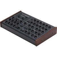
- USER MANUAL
- 2 INTRODUCTION AND CONNECTIONS
- 5 A SHORT INTRODUCTION INTO SOUND PHYSICS
- 16 SUBTRACTIVE SYNTHESIS AND SUBTRACTIVE SYNTHESIZERS
- 25 HOW THE BULLFROG WORKS
- 74 PATCH NOTES
- 84 SAFETY INSTRUCTIONS
- RICHIE HAWTIN
- FEATURES
- WHAT'S INCLUDED
- A SHORT INTRODUCTION INTO SOUND PHYSICS
- WHAT IS A SOUND
- A PITCH
- AMPLITUDE OR VOLUME
- TIMBRE
- WAVEFORMS
- OVERTONES AND HARMONICS
- TEST YOURSELF A SHORT INTRODUCTION INTO SOUND PHYSICS
- SUBTRACTIVE SYNTHESIS AND SUBTRACTIVE SYNTHESIZERS
- SUBTRACTIVE SYNTHESIS
- FILTERS
- AMPLIFIERS
- VOLTAGE CONTROL
- SUBTRACTIVE SYNTHESIZER
- TEST YOURSELF SUBTRACTIVE SYNTHESIS AND SUBTRACTIVE SYNTHESIZERS
- HOW THE BULLFROG WORKS
- VOLTAGE CONTROLLED OSCILLATOR (VCO)
- NOISE GENERATOR AND MIXER
- VOLTAGE CONTROLLED OSCILLATOR PATCH 1 SINEWAVE EXPLORATION
- VOLTAGE CONTROLLED OSCILLATOR PATCH 2 PULSEWAVE EXPLORATION
- VOLTAGE CONTROLLED OSCILLATOR PATCH 3 NOISE EXPLORATION
- VOLTAGE CONTROLLED OSCILLATOR PATCH 4 MIXING OF WAVEFORMS
- VOLTAGE CONTROLLED OSCILLATOR PATCH 5 CONTROLLING THE PITCH OF THE OSCILLATOR WITH A KEY- BOARD
- TEST YOURSELF HOW THE VOLTAGE CONTROLLED OSCILLATOR WORKS
- VOLTAGE CONTROLLED FILTER (VCF)
- VOLTAGE CONTROLLED FILTER PATCH 1
- VOLTAGE CONTROLLED FILTER PATCH 2
- VOLTAGE CONTROLLED FILTER PATCH 3
- TEST YOURSELF HOW THE VOLTAGE CONTROLLED FILTER WORKS
- VOLTAGE CONTROLLED AMPLIFIER (VCA)
- VOLTAGE CONTROLLED AMPLIFIER PATCH 1
- VOLTAGE CONTROLLED AMPLIFIER PATCH 2
- TEST YOURSELF HOW VOLTAGE CONTROLLED AMPLIFIER WORKS
- CONTROL VOLTAGE (CV) SOURCES
- ENVELOPE GENERATORS
- ENVELOPE GENERATOR PATCH 1
- ENVELOPE GENERATOR PATCH 2
- ENVELOPE GENERATOR PATCH 3
- ENVELOPE GENERATOR PATCH 4
- OSCILLATOR PATCH 6 VIBRATO
- VOLTAGE CONTROLLED FILTER PATCH 4 A WAH-WAH EFFECT
- VOLTAGE CONTROLLED AMPLIFIER PATCH 3 A TREMOLO EFFECT
- TEST YOURSELF HOW ENVELOPE GENERATORS WORK
- SAMPLE & HOLD
- SAMPLE & HOLD PATCH 1
- SAMPLE & HOLD PATCH 2
- SAMPLE & HOLD PATCH 3
- SAMPLE & HOLD PATCH 4
- SAMPLE & HOLD PATCH 5
- TEST YOURSELF
- HOW SAMPLE & HOLD WORKS
- DIVIDER
- DIVIDER PATCH 1
- DIVIDER PATCH 2
- DIVIDER PATCH 3
- DIVIDER PATCH 4
- TEST YOURSELF HOW THE DIVIDER WORKS
- VOICECARDS
- MIDI IMPLEMENTATION AND CONFIGURATION
- CONFIGURATION AND FIRMWARE UPDATE
- PATCH NOTES
- SAFETY INSTRUCTIONS DISPOSAL
- WARRANTY
Brand : Erica Synths
Model : Bullfrog
Category : Keyboard