
VP50-2 - Detector FLIR - Free user manual and instructions
Find the device manual for free VP50-2 FLIR in PDF.


| Product Type | Non-Contact Voltage Detector + Flashlight |
| Brand | FLIR |
| Model | VP50-2 (110 V regions) |
| Dimensions | 6.24 x 1.02 x 1.14 in (158.5 x 26 x 29 mm) |
| Weight | 2.1 oz (59 g) including batteries |
| Power Supply | 2 × AAA (LR03) batteries |
| Voltage Detection Range (Low Sensitivity) | 90 ~ 1000 V AC (VP50-2) |
| Voltage Detection Range (High Sensitivity) | 24 ~ 1000 V AC |
| Frequency Range | 45 ~ 65 Hz |
| Safety Rating | CAT IV 1000 V |
| Ingress Protection | IP54 |
| Battery Life | 5 hours continuous (flashlight off) |
| Auto Power Off | Device after 3 minutes; flashlight after 30 minutes |
| Drop Test | 9.8 ft (3 m) |
| Alarm Types | Audible beeper, vibration, multi-color LED flashing |
| Flashlight | Bright LED at tip + separate flashlight button |
| Operating Temperature | 14°F ~ 122°F (-10°C ~ 50°C) |
| Storage Temperature | -4°F ~ 140°F (-20°C ~ 60°C) |
| Warranty | Three-Year Limited Warranty |
| Cleaning | Damp cloth with mild detergent; compressed air for lens |
| Battery Replacement | User-replaceable; recycle used batteries |
Frequently Asked Questions - VP50-2 FLIR
User questions about VP50-2 FLIR
0 question about this device. Answer the ones you know or ask your own.
Ask a new question about this device
Download the instructions for your Detector in PDF format for free! Find your manual VP50-2 - FLIR and take your electronic device back in hand. On this page are published all the documents necessary for the use of your device. VP50-2 by FLIR.
USER MANUAL VP50-2 FLIR
USER MANUAL Non-Contact Voltage Detector + Flashlight
VP50-2 (110V regions) and VP52-2 (220V regions)
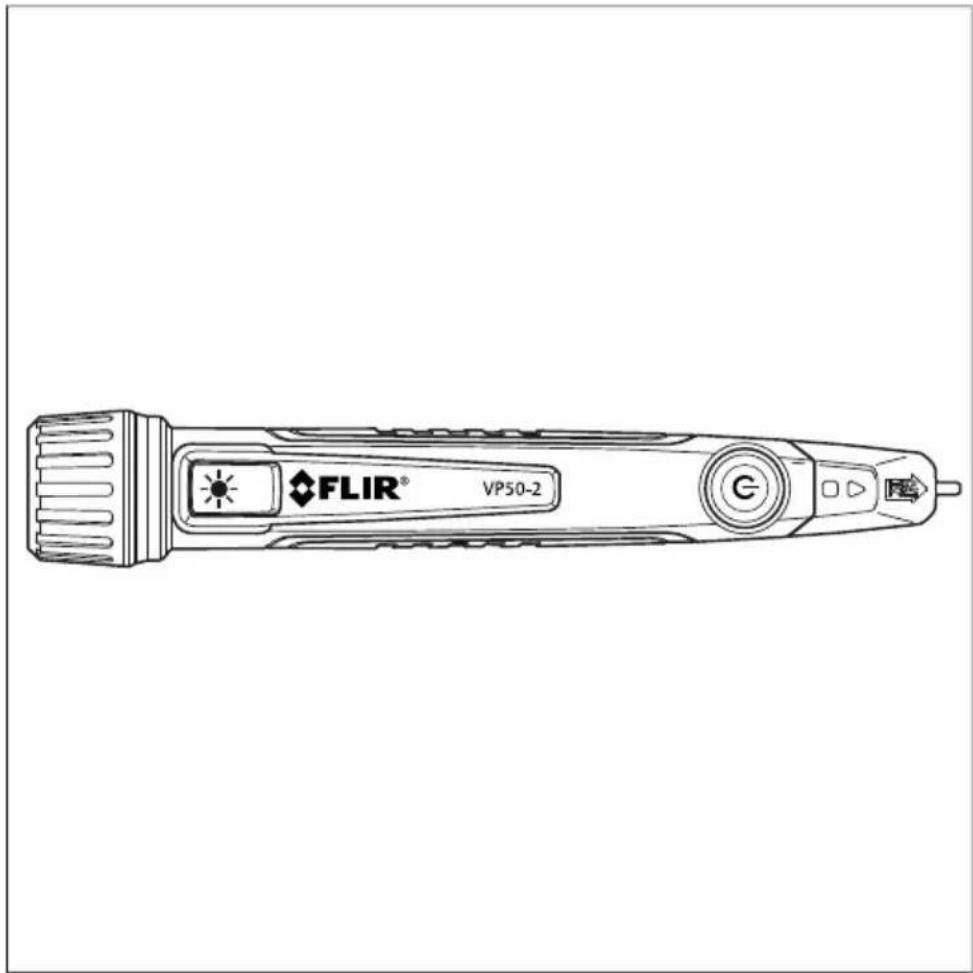
USER MANUAL Non-Contact Voltage Detector + Flashlight
Table of contents
1 Advisories....1
1.1 Copyright.... 1
1.2 Quality Assurance .... 1
1.3 Documentation .... 1
1.4 Disposal of Electronic Waste.... 1
2 Introduction....2
3 Key Features....3
4 Safety 4
4.1 Safety Symbols 5
5 Descriptions ....6
5.1 Product Description....6
5.2 Button, Indicator, and Beeper Descriptions.... 6
6 Operation 8
6.1 Low (normal) and High Sensitivity Modes......8
6.2 Basic Operation 8
6.3 Flashlight 9
6.4 Low Battery Indication 9
6.5 Auto Power OFF (APO)....9
7 Maintenance.... 10
7.1 Cleaning and Storage.... 10
7.2 Battery Replacement.... 10
8 Specifications.... 11
9 Customer Support.... 12
9.1 Corporate Headquarters 12
10 Three-Year Warranty 13
1 Advisories
1.1 Copyright
©2020 FLIR Systems, Inc. All rights reserved worldwide.
No parts of the software including source code may be reproduced, transmitted, transcribed or translated into any language or computer language in any form or by any means, electronic, magnetic, optical, manual or otherwise, without the prior written permission of FLIR Systems.
The documentation must not, in whole or part, be copied, photocopied, reproduced, translated or transmitted to any electronic medium or machine-readable form without prior consent, in writing, from FLIR Systems. Names and marks appearing on the products herein are either registered trademarks or trademarks of FLIR Systems and/or its subsidiaries. All other trademarks, trade names or company names referenced herein are used for identification only and are the property of their respective owners.
1.2 Quality Assurance
The Quality Management System under which these products are developed and manufactured has been certified in accordance with the ISO 9001 standard. FLIR Systems is committed to a policy of continuous development; therefore, we reserve the right to make changes and improvements on any of the products without prior notice.
1.3 Documentation
To access the latest manuals and notifications, go to the Download tab at: https://support.flir.com. It only takes a few minutes to register online. In the download area you will also find the latest releases of manuals for our other products, as well as manuals for our historical and obsolete products.
1.4 Disposal of Electronic Waste

As with most electronic products, this equipment must be disposed of in an environmentally friendly way, and in accordance with existing regulations for electronic waste. Please contact your FLIR Systems representative for more details.
2 Introduction
The VP5x-2 detects the presence of AC voltage at electrical outlets, junction strips, electrical circuits, and other devices without having to contact the device physically. The VP50-2 (110 V regions) has a minimum excitation voltage of 90 V AC (this is its normal, or low sensitivity, mode); The VP52-2 (220 V regions) has a minimum excitation voltage of 190 V AC (this is its normal, or low sensitivity, mode). Both models have a high sensitivity mode allowing detection down to 24 V AC. Tactile vibration, audible beeper, and visual cues alert the user when AC voltage is present.
Visit https://www.support.flir.com/prodreg to register your VP5x-2 and to read the three-year warranty text.
3 Key Features
- Beeper sound
• Vibration feedback alarms - Optimized High/Low sensitivity ranges
- Multi-color LED alarm indicators
- Bright flashlight
• Dual LED illuminator at probe tip
• ON/OFF button with auto power off (APO)
• CAT IV 1000 V safety rated - Low battery indication (status LED flashing amber)
- Robust pocket clip
- Limited Three-Year Warranty
• 9.8 ft. (3 m) drop-tested
4 Safety
NOTE
• This device will not detect DC voltage.
- Before and after each use, verify proper operation by testing on a known ‘live’ circuit (within the stated range of this device).
• Static electricity can randomly trigger this device, this is normal for a device of this type.
• In bright light conditions, the indicators will be less visible.

WARNING
- Please read, understand and follow all warnings, cautions, safety information and instructions before operating this device. Failure to do so can result in death or serious injury.
- Keep hands and fingers on the body of the probe when measuring, do not touch live circuits.
- Risk of electric shock and burn. Contact with live circuits could result in death or serious injury.
- This device may not detect voltage if: The user is not holding the tester, the device is at too long a distance from the voltage source, or if the tested frequency is outside of the specified range.
- Do not attempt to detect voltages outside the specified range.

CAUTION
• Use caution with voltages > 30 V AC.
- If the device indicates that no voltage is present, voltage may still be present, use caution and double check your test results.
- Never assume neutral or ground wires are de-energized. Neutrals in multi-wire branch circuits may be energized when disconnected and must be retested before handling.
- Voltage detection performance is affected by varying electrical socket designs and insulation thickness/type; use caution.
- Do not use this device if it is wet, does not power up properly, appears damaged, or if does not function properly.
• Always wear protective clothing and eye-ware.
- Do not use this device for purposes that have not been outlined in the user documentation.
- Do not attempt to repair this device. There are no user-serviceable parts.
- Do not expose this device to extremes in temperature or humidity.
4.1 Safety Symbols
| [2T4D] | Read, understand, and follow all safety information, warnings, and cautions before attempting to operate this device. Failure to do so can result in death or serious injury. |
| [860H] | Risk of electrical shock exists under normal use. |
 | Double insulation. |
5 Descriptions
5.1 Product Description
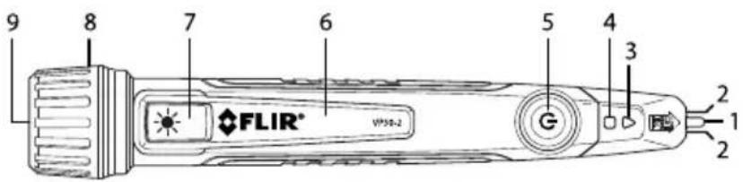
Figure 5.1 Product Description
- AC Voltage sensor
- Tip lighting
- Alarm indicator
- Status indicator
- Power button: ON (short press); OFF (long press); Low/high sensitivity toggle (short press with meter ON)
- Pocket clip
- Flashlight ON/OFF button (long press)
- Battery compartment access cap
- Flashlight
5.2 Button, Indicator, and Beeper Descriptions
 | Power buttonShort press to switch the meter ON; Long Press to switch OFF.When meter is powered, short press to toggle high and low (normal) sensitivity. |
 | Flashlight buttonLong press to switch the flashlight ON/OFF (the detector does not operate when the flashlight is ON). |
| [4AOW] | Alarm indicatorWhen voltage is detected, the alarm indicator flashes red (normal, low sensitivity, mode) or flashes amber (high sensitivity mode).Status IndicatorWhen the meter is functioning normally and not in an alarm condition, the status indicator glows solid green (normal, low sensitivity, mode) or solid amber (high sensitivity mode).If the status indicator is flashing amber, please replace the batteries.If the status indicator is flashing red, the meter is malfunctioning, please return the meter for service. |
| BEEPER | In test mode, the beeper sounds when voltage is detected. The beeper also sounds when a button is pressed to change a function or to power ON or OFF. |
6 Operation

WARNING
Do not use this instrument before testing on a known live circuit.

WARNING
Keep hands and fingers on the probe body, away from the probe tip.
6.1 Low (normal) and High Sensitivity Modes
The meter operates in one of two modes: normal (low sensitivity), mode, or high sensitivity mode. The excitation voltage required to activate the meter alarm is much lower in the high sensitivity mode, see below.
- In Normal (low sensitivity) mode, the minimum excitation voltage is 90 V AC (VP50–2) or 190 V AC (VP52–2).
- In high sensitivity mode, the minimum excitation voltage is 24 V AC.
- Toggle the low and high sensitivity modes by short pressing the power button (with the unit powered up).
- In normal (low sensitivity) mode, the status indicator illuminates solid green.
- In high sensitivity mode, the status indicator illuminates solid amber.
- The VP50–2 is intended for 110 V AC regions and the VP52–2 is intended for 220 V AC regions.

CAUTION
Static electricity and other stray sources of energy can randomly trigger the sensor, this is normal. Random triggering is more likely in high sensitivity mode but can also occur in the low sensitivity mode.
6.2 Basic Operation
- Short press the power button (5) to switch the meter ON. The meter vibrates briefly, beeps twice, and the tip lights (2) turn ON.
-
When ON, the status indicator (4) should be solid green, indicating a proper working condition.
-
If the status indicator is flashing amber, replace the batteries.
-
If the status indicator is flashing red, the meter is malfunctioning (contact FLIR for Service).
-
Once powered, short press the power button to toggle the sensitivity modes. The beeper will sound when the sensitivity is changed. See the Low and High Sensitivity Modes section for additional information.

WARNING
Test on a known live circuit before testing on an uncertain circuit. Varying electrical socket designs and insulation thickness/types can affect voltage detection performance.
-
Hold the AC voltage sensor (1) very close to the voltage source.
-
If voltage is present, the meter vibrates, beeps, and the alarm indicator (3) flashes.
-
With voltage detected, in the normal (low sensitivity) mode, the alarm indicator flashes red.
-
With voltage detected, in high sensitivity mode, the alarm indicator flashes amber.
-
To switch OFF, long press the power button. The meter beeps once and the status indicator and tip lights switch off.
6.3 Flashlight
To turn the flashlight (9) on or off, long press the flashlight button (7), the meter will beep. Note that the voltage detector does not operate while the flashlight is ON.
6.4 Low Battery Indication
The status indicator (4) flashes amber when the batteries need replacing. After 1 minute of flashing, the meter automatically switches OFF. See the Maintenance section for battery replacement instructions.
6.5 Auto Power OFF (APO)
The meter switches OFF after 3 minutes of inactivity. The flashlight switches OFF after 30 minutes, regardless of activity.
7 Maintenance
7.1 Cleaning and Storage
With the meter OFF, clean with a damp cloth and mild detergent, do not use harsh detergents, abrasives or solvents.
Use compressed air to clear dust from the flashlight lens. Clean the lens with a commercial lens cleaner if necessary.
Ensure that the device is dry before performing tests.
When storing for long periods, remove the batteries and store separately.
7.2 Battery Replacement
- Switch the meter OFF before replacing the batteries.
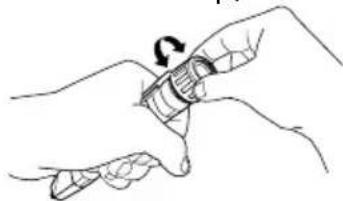
- Unscrew the cap, as shown.
natural_image
Line drawing of two hands holding a cylindrical object with a curved arrow indicating rotation (no text or symbols)-
Replace the 2 x 'AAA' batteries, observing correct polarity, as shown on the outside of the case, near the compartment cap.
-
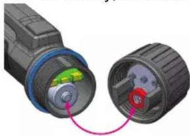
Secure the cap, ensuring that the red plastic ring in the battery cap aligns with the battery, as shown.
natural_image
Close-up of two mechanical components with colored internal structures, connected by a pink arrow (no text or symbols visible)- Check that the device powers up correctly before attempting to make measurements.

Recycle used batteries; do not dispose in household trash. Follow all regulations with respect to the disposing of this device at the end of its lifecycle.
8 Specifications
| VP50-2 excitation voltage in normal, low sensitivity, mode | 90 V AC minimum |
| VP52-2 excitation voltage in normal, low sensitivity, mode | 190 V AC minimum |
| Voltage ranges | 90 ~ 1000 V AC (VP50-2) in normal, low sensitivity, mode |
| 190 ~ 1000 V AC (VP52-2) in normal, low sensitivity, mode | |
| 24 ~ 1000 V AC in high sensitivity mode (VP50-2 and VP52-2) | |
| Category safety rating | CAT IV - 1000 V |
| Frequency range 45 ~ 65 Hz | |
| Operating temperature | 14°F ~ 122°F (-10°C ~ 50°C) |
| Storage temperature | -4°F ~ 140°F (-20°C ~ 60°C) |
| Dimensions | 6.24 x 1.02 x 1.14 in. (158.5 x 26 x 29 mm) |
| Weight 2.1 oz. (59 g) including batteries | |
| Battery life | 5 hours continuous with the flashlight off |
| Battery type 2 × ‘AAA’ (LR03) | |
| APO | Device powers OFF after 3 minutes of inactivity |
| For flashlight: After 30 minutes | |
| Drop-proof 9.8 ft. (3 m) | |
| IP Rating IP54 | |
| Agency approvals CE, cULus, RCM | UL listing is not an indication or a verification of the accuracy of the meter. |
9 Customer Support
Repair, Calibration, and Technical Support: https://support.flir.com.
9.1 Corporate Headquarters
FLIR Systems, Inc.
27700 SW Parkway Avenue
Wilsonville, OR 97070, USA
10 Three-Year Warranty
This product is protected by FLIR's 3-Year Limited Warranty. Visit https://support.flir.com/prodreg to read the 3-Year Limited Warranty document.
Website
http://www.flir.com
Customer support
http://support.flir.com
Copyright
© 2020, FLIR Systems, Inc. All rights reserved worldwide.
Disclaimer
Specifications subject to change without further notice. Models and accessories subject to regional market considerations. License procedures may apply. Products described herein may be subject to US Export Regulations. Please refer to exportquestions@flir.com with any questions.

- USER MANUAL Non-Contact Voltage Detector + Flashlight
- Table of contents
- Advisories....1
- Introduction....2
- Key Features....3
- Safety 4
- Descriptions ....6
- Operation 8
- Maintenance.... 10
- Specifications.... 11
- Customer Support.... 12
- Three-Year Warranty 13
- Advisories
- Copyright
- Quality Assurance
- Documentation
- Disposal of Electronic Waste
- Introduction
- Key Features
- Safety
- NOTE
- WARNING
- CAUTION
- Safety Symbols
- Descriptions
- Product Description
- Button, Indicator, and Beeper Descriptions
- Operation
- Low (normal) and High Sensitivity Modes
- Basic Operation
- Flashlight
- Low Battery Indication
- Auto Power OFF (APO)
- Maintenance
- Cleaning and Storage
- Battery Replacement
- Specifications
- Customer Support
- Corporate Headquarters
- Three-Year Warranty
- Website
- Customer support
- Copyright
- Disclaimer
Brand : FLIR
Model : VP50-2
Category : Detector