DVX-2265-4K - Switch AMX - Free user manual and instructions
Find the device manual for free DVX-2265-4K AMX in PDF.


| Product Type | All-in-One Digital Video Presentation Switcher (6x2) |
| Model | AMX DVX-2265-4K |
| Dimensions (W x H x D) | 440 mm x 88 mm x 380.2 mm (without mounting brackets) |
| Weight | 9.56 kg |
| Power Supply | AC 100-240V, 50/60Hz, 10A |
| Power Consumption | 63W typical (without amplifier), 103W typical (with amplifier) |
| Main Functions | Video/Audio matrix switcher with built-in NetLinx controller, scalers, HDMI 2.0 (4K@60Hz 4:4:4), HDCP 2.2, HDR bypass, audio DSP, mic mixer, 120W amplifier, Dante I/O, web UI control |
| Video Inputs | 4 HDMI, 2 DXLink (RJ-45) |
| Video Outputs | 2 HDMI, 1 DXLink (RJ-45, mirrors HDMI 2) |
| Audio Inputs | 2 analog line-level, 6 mic/line (mono), 4 stereo Dante (via 2 RJ-45), embedded audio from HDMI/DXLink |
| Audio Outputs | 2 analog line-level, 1 amplified (2x120W@8Ω or 1x120W@70V/100V), 4 stereo Dante, HDMI audio |
| Control Interfaces | Front panel, NetLinx (ICSP), WebConsole, RS-232, IR/Serial, I/O, relay, ICSLAN, LAN |
| Supported Video Resolutions | Up to 3840x2160@60Hz (4:4:4) in scaler or bypass mode; extensive VESA and SMPTE formats |
| Supported Audio Formats | PCM 2.0/5.1/7.1, Dolby TrueHD, Dolby Atmos, DTS-HD, DTS:X (bypass); PCM 2.0 (scaler) |
| Care and Cleaning | Clean only with a dry cloth. Do not use liquid cleaners or aerosols. |
| Safety Warnings | Do not expose to rain or moisture. Use only with specified accessories. Keep ventilation openings unobstructed. Refer servicing to qualified personnel. |
| Spare Parts and Repairability | No user-serviceable parts inside. Contact AMX authorized service for repairs. Use only manufacturer-specified replacement parts. |
| Operating Environment | Temperature: 0°C to 40°C; Humidity: 5% to 85% non-condensing; Altitude: up to 2 km |
| Certifications | CE, FCC, ETL, PSE, RCM, RoHS, REACH |
| Package Contents | DVX-2265-4K unit, 3 AC power cords (US/UK/EU), Phoenix connectors, IR emitters, rack mount brackets, rubber feet, Quick Start Guide |
Frequently Asked Questions - DVX-2265-4K AMX
User questions about DVX-2265-4K AMX
0 question about this device. Answer the ones you know or ask your own.
Ask a new question about this device
Download the instructions for your Switch in PDF format for free! Find your manual DVX-2265-4K - AMX and take your electronic device back in hand. On this page are published all the documents necessary for the use of your device. DVX-2265-4K by AMX.
USER MANUAL DVX-2265-4K AMX
natural_image
Front view of a black audio or video player equipment unit with control panel and drive buttons (no visible text or symbols)Important Safety Instructions
READ these instructions.
KEEP these instructions.
HEED all warnings.
FOLLOW all instructions.
DO NOT use this apparatus near water.
CLEAN ONLY with dry cloth.
DO NOT block any ventilation openings. Install in accordance with the manufacturer's instructions.
DO NOT install near any heat sources such as radiators, heat registers, stoves, or other apparatus (including amplifiers) that produce heat.
DO NOT defeat the safety purpose of the polarized or grounding type plug. A polarized plug has two blades with one wider than the other. A grounding type plug has two blades and a third grounding prong. The wider blade on the third prong are provided for your safety. If the provided plug does not fit into your outlet, consult an electrician for replacement of the obsolete outlet.
PROTECT the power cord from being walked on or pinched, particularly at plugs, convenience receptacles, and the point where they exit from the apparatus.
ONLY USE attachments/accessories specified by the manufacturer.

USE ONLY with a cart, stand, tripod, bracket, or table specified by the manufacturer, or sold with the apparatus. When a cart is used, use caution when moving the cart/apparatus combination to avoid injury from tip-over.
UNPLUG this apparatus during lightning storms or when unused for long periods of time.
REFER all servicing to qualified service personnel. Servicing is required when the apparatus has been damaged in any way, such as power-supply cord or plug is damaged, liquid has been spilled or objects have fallen into the apparatus, the apparatus has been exposed to rain or moisture, does not operate normally, or has been dropped.
Use the mains plug to disconnect the apparatus from the mains.
WARNING: TO REDUCE THE RISK OF FIRE OR ELECTRIC SHOCK, DO NOT EXPOSE THIS APPARATUS TO RAIN OR MOSITURE.
DO NOT EXPOSE THIS APPARATUS TO DRIPPING OR SPLASHING AND ENSURE THAT NO OBJECTS FILLED WITH LIQUIDS, SUCH AS VASES, ARE PLACED ON THIS APPARATUS.
THE MAINS PLUG OF THE POWER SUPPLIER CORD SHALL REMAIN READILY OPERABLE.
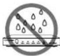
- Do not expose this apparatus to rain, moisture, dripping or splashing and that no objects filled with liquids, such as vases, shall be placed on the apparatus.
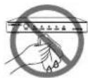
- Clean this apparatus only with dry cloth.
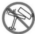
- Do not install or place this unit in a bookcase, built-in cabinet or in another confined space. Ensure the unit is well ventilated.
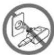
- Unplug this apparatus during lightning storms or when unused for long periods of time.
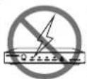
- To prevent risk of electric shock or fire hazard due to overheating, do not obstruct the unit's ventilation openings with newspapers, tablecloths, curtains, and similar items.
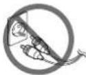
- Protect the power cord from being walked on or pinched particularly at plugs.
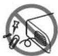
- Do not install near any heat sources such as radiators, heat registers, stoves, or other apparatus (including amplifiers) that produce heat.
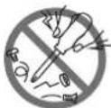
- Only use attachments / accessories specified by the manufacturer.
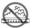
- Do not place sources of naked flames, such as lighted candles, on the unit.
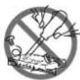
- Refer all servicing to qualified service personnel.

TO PREVENT ELECTRIC SHOCK DO NOT REMOVE TOP COVER. NO USER SERVICEABLE PARTS INSIDE. REFER SERVICING TO QUALIFIED SERVICE PERSONNEL.

TO COMPLETELY DISCONNECT THIS APPARATUS FROM THE AC MAINS. DISCONNECT THE POWER SUPPLY CORD PLUG FROM THE AC RECEPTACLE. THE MAINS PLUG OF THE POWER SUPPLY CORD SHALL REMAIN READILY OPERABLE.
WATCH FOR THESE SYMBOLS:

The exclamation point triangle is used to alert the user to important operating or maintenance instructions.

The lightning bolt triangle is used to alert the user to the risk of electrical shock.

ESD Warning: The icon to the left indicates text regarding potential danger associated with the discharge of static electricity from an outside source (such as human hands) into an integrated circuit, often resulting in damage to the circuit.
WARNING: To reduce the risk of fire or electrical shock, do not expose this apparatus to rain or moisture.
WARNING: No naked flame sources – such as lighted candles – should be placed on the product.
WARNING: Equipment shall be connected to a MAINS socket outlet with a protective earthing connection.
WARNING: This product is intended to be operated ONLY from the voltages listed on the back panel or the recommended, or included, power supply of the product. Operation from other voltages other than those indicated may cause irreversible damage to the product and void the products warranty. The use of AC Plug Adapters is cautioned because it can allow the product to be plugged into voltages in which the product was not designed to operate. If you are unsure of the correct operational voltage, please contact your local distributor and/or retailer. If the product is equipped with a detachable power cord, use only the type provided, or specified, by the manufacturer or your local distributor.
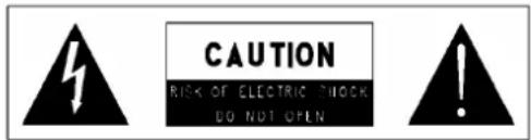
WARNING: Do Not Open! Risk of Electrical Shock. Voltages in this equipment are hazardous to life. No user-serviceable parts inside. Refer all servicing to qualified service personnel.
MAGNETIC FIELD
CAUTION! Do not locate sensitive high-gain equipment such as preamplifiers or tape decks directly above or below the units. Because this amplifier has a high-power density, it has a strong magnetic field which can induce hum into unshielded devices that are located nearby. The field is strongest just above and below the unit.
If an equipment rack is used, we recommend locating the amplifier(s) in the bottom of the rack and the preamplifier or other sensitive equipment at the top.
WEEE Notice
The Directive on Waste Electrical and Electronic Equipment (WEEE), which entered into force as European law on 14/02/2014, resulted in a major change in the treatment of electrical equipment at end-of-life.
The purpose of this Directive is, as a first priority, the prevention of WEEE, and in addition, to promote the reuse, recycling and other forms of recovery of such wastes so as to reduce disposal. The WEEE logo on the product or on its box indicating collection for electrical and electronic equipment consists of the crossed-out wheeled bin, as shown below.
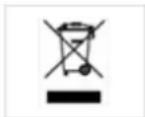
This product must not be disposed of or dumped with your other household waste. You are liable for the disposal of all your electronic or electrical waste equipment by relocating over to the specified collection point for recycling of such hazardous waste. Isolated collection and proper recovery of your electronic and electrical waste equipment at the time of disposal will allow us to help conserving natural resources. Moreover, proper recycling of the electronic and electrical waste equipment will ensure safety of human health and environment. For more information about electronic and electrical waste equipment disposal, recovery, and collection points, please contact your local city center, household waste disposal service, shop from where you purchased the equipment, or manufacturer of the equipment.
RoHS Compliance
This product is in compliance with Directive 2011/65/EU and (EU) 2015/863 of the European Parliament and of the Council of 31/03/2015 on the restriction of the use of certain hazardous substances in electrical and electronic equipment.
REACH
REACH (Regulation No 1907/2006) addresses the production and use of chemical substances and their potential impacts on human health and the environment. Article 33 (1) of REACH Regulation requires suppliers to inform
the recipients if an article contains more than 0.1% (per weight per article) of any substance(s) on the Substances of Very High Concern (SVHC) Candidate List ('REACH candidate list').
This product contains the substance “lead” (CAS-No. 7439-92-1) in a concentration of more than 0.1% per weight.
At the time of release of this product, except for the lead substance, no other substances of REACH candidate list are contained in a concentration of more than 0.1% per weight in this product.
Note: on June 27, 2018, lead was added to the REACH candidate list. The inclusion of lead in the REACH candidate list does not mean that lead-containing materials pose an immediate risk or results in a restriction of permissibility of its use.
CAUTION FCC AND IC STATEMENT FOR USERS (USA AND CANADA ONLY)
This device complies with part 15 of the FCC Rules. Operation is subject to the following two conditions: (1) this device may not cause harmful interference, and (2) this device must accept any interference received, including interference that may cause undesired operation.
CAN ICES-3 (B)/NMB-3(B)
FCC SDOC SUPPLIER'S DECLARATION OF CONFORMITY
HARMAN International hereby declares that this equipment is in compliance with the FCC part 15 Subpart B. The declaration of conformity may be consulted in the support section of our web site, accessible from www.AMX.com.
Federal Communication Commission Interference Statement
This equipment has been tested and found to comply with the limits for a Class B digital device, pursuant to Part 15 of the FCC Rules. These limits are designed to provide reasonable protection against harmful interference in a residential installation. This equipment generates, uses and can radiate radio frequency energy and, if not installed and used in accordance with the instructions, may cause harmful interference to radio communications.
However, there is no guarantee that interference will not occur in a particular installation. If this equipment does cause harmful interference to radio or television reception, which can be determined by turning the equipment off and on, the user is encouraged to try to correct the interference by one or more of the following measures;
• Reorient or relocate the receiving antenna.
- Increase the separation between the equipment and receiver.
- Connect the equipment into an outlet on a circuit different from that to which the receiver is connected.
- Consult the dealer or an experienced radio/TV technician for help.
Caution: Changes or modifications not expressly approved by Harman could void the user's authority to operate the equipment.
CONTENTS
INTRODUCTION....3
OVERVIEW 3
COMMON APPLICATION 3
AUDIO PROCESSING 3
INTEGRATED CONTROL....3
BATTERY LIFE....3
FEATURES 4
PACKAGE CONTENTS 4
SPECIFICATIONS 5
TRANSMISSION DISTANCE....7
INSTALLATION 8
WIRING AND DEVICE CONNECTORS 9
OVERVIEW....9
FRONT PANEL CONTROLS AND INDICATORS 10
LEDS 10
LCD DISPLAYS....10
TAKE PUSHBUTTON 11
VIDEO MENU PUSHBUTTON....11
AUDIO MENU PUSHBUTTON....11
NAVIGATION PUSHBUTTONS 12
STATUS PUSHBUTTON 12
EXIT PUSHBUTTON 13
VIDEO/AUDIO MUTE PUSHBUTTONS....13
PROGRAM PORT 13
USB PORT 13
REAR PANEL AUDIO INPUTS AND AUDIO OUTPUTS 14
AUDIO INPUTS 14
HDMI INPUTS....15
MIC/LINE INPUTS....15
AMP OUTPUTS 15
AUDIO OUTPUTS 16
DANTE INPUTS/OUTPUTS 17
REAR PANEL VIDEO INPUTS AND OUTPUTS 17
HDMI INPUTS....17
DXLINK INPUTS 18
DXLINK/HDMI OUTPUTS 18
TWISTED PAIR CABLE PINOUTS....19
IMPORTANT TWISTED PAIR CABLING REQUIREMENTS AND RECOMMENDATIONS....19
REAR PANEL CONTROL AND POWER 20
RS232 PORTS 20
RELAY PORTS 20
I/O PORTS 20
IR/SERIAL PORT: CONNECTION AND WIRING 21
CONFIGURATION DIP SWITCH....21
ICS LAN PORT 21
USB PORT 22
USB A/B PORTS 23
ID PUSHBUTTON 23
LAN 100/1000....23
POWER CONNECTOR 24
AUDIO/VIDEO CONFIGURATIONS....25
OVERVIEW 25
USING THE FRONT PANEL BUTTONS 25
VIDEO SETTINGS....25
AUDIO SETTINGS....27
SWITCH MENU 30
STATUS MENU 30
DVX WEBCONSOLE 31
ACCESSING THE WEBCONSOLE 31
CONTROLLER CONFIGURATION OPTIONS....31
USING A WEB BROWSER 32
FIRMWARE UPGRADE 46
BEFORE YOU START....46
REQUIRED ORDER OF FIRMWARE UPDATES FOR DVX CONTROLLERS....46
SENDING FIRMWARE (*.KIT) FILES TO THE DVX 46
PROGRAMMING 47
OVERVIEW 47
NETLINX CHANNELS 47
NETLINX LEVELS 48
PORT FUNCTIONALITY MAPPING 49
SEND_COMMANDS 51
WARRANTY TERMS AND CONDITIONS....132
Introduction
Overview
The All-In-One Presentation Switchers combine all of the components you need to control/automate any environment into a simple, flexible, comprehensive solution including control, analog and digital audio/video inputs, audio and video switching, video scaling, local and remote distribution, plus audio mixing, and amplification - all in a single box.
The All-in-One Presentation Switchers covered in this manual include:
| All-in-One Presentation Switchers | |
| Name | Description |
| DVX-3266-4K | 8 x 4 All-In-One Digital Video Presentation Switcher |
| DVX-2265-4K | 6 x 2 All-In-One Digital Video Presentation Switcher |
Common Application
Enova DVX All-in-One Presentation Switchers are ideal solutions when used to simplify A/V control and distribution in sophisticated presentation environments and conference rooms, including those supporting audio and video conferencing. It also fits well in classrooms and auditoriums that need multiple displays, or video previewing.
Audio Processing
Enova DVX All-in-One Presentation Switchers feature built-in audio mixing and equalization for four independent, assignable audio output groups to accommodate the size, furnishings, surfaces, and functional requirements in every room. The amplified audio output, two-line level audio outputs, 4 stereo Dante audio outputs and all HDMI audio outputs can be assigned individually to any of the four audio output groups. The amplifier outputs two channels at 120 Watts each into 8-ohms or 120 Watts into a single mono channel at 70 or 100 Volts.
Integrated Control
The Enova DVX-3266-4K and DVX-2265-4K have built-in NX-Series NetLinx Integrated Controllers. All DVX models include two (2) RS-232 ports, two (2) IR/Serial ports, two (2) Digital I/O ports and two (2) relay ports for control of third-party equipment. All DVX models also include a front control panel for an added level of convenience.
Battery Life
Enova DVX-3266-4K and DVX-2265-4K All-in-One Presentation Switchers use a combination lithium battery and clock crystal package. The battery is a commonly available CR2032 lithium battery. The battery has an average shelf life of 10 years. In normal use, the time will be shorter than the average shelf life depending on the amount of time the unit has no external power for the clock circuit.
Typical useful life of the battery is 8 years under the specified temperature range. (see Operating Environment in the Specifications table for each type of DVX in next two chapters for more information.)
Features
• Video/Audio matrix switcher;
• Built in NetLinx Controller;
• Built-in scalers;
• Supports HDMI 2.0 with resolution up to 4K@60Hz 4:4:4 In/Out;
• Supports HDCP 2.2;
• Supports HDR when scaler is in bypass mode;
• Supports audio breakaway and embedding, audio DSP, mic mixer, 120W amplifier, Dante inputs and outputs
- Supports multiple control methods such as Front Panel buttons, ICSP Commands and mobile-friendly web interface.
Package Contents
The following items are included with the DVX-3266-4K:
[1] DVX-3266-4K
• [1] AC Power Cord with US Pins
• [1] AC Power Cord with UK Pins
• [1] AC Power Cord with EU Pins
• [8] 3-Pin, 3.5mm Phoenix Male Connector
• [3] 4-Pin, 3.5mm Phoenix Male Connector
• [4] 5-Pin, 3.5mm Phoenix Male Connector
• [1] 3-Pin, 5.08mm Phoenix Male Connector
• [1] 4-Pin, 5.08mm Phoenix Male Connector
• [2] IR Emitters
• [2] Front Rack Mounting Brackets (Attached)
• [4] Rubber Feet (Attached)
• [1] Quick Start Guide
The following items are included with the DVX-2265-4K:
• [1] DVX-2265-4K
• [1] AC Power Cord with US Pins
• [1] AC Power Cord with UK Pins
• [1] AC Power Cord with EU Pins
• [8] 3-Pin, 3.5mm Phoenix Male Connector
• [3] 4-Pin, 3.5mm Phoenix Male Connector
• [4] 5-Pin, 3.5mm Phoenix Male Connector
• [1] 3-Pin, 5.08mm Phoenix Male Connector
• [1] 4-Pin, 5.08mm Phoenix Male Connector
• [2] IR Emitters
• [2] Front Rack Mounting Brackets (Attached)
• [4] Rubber Feet (Attached)
• [1] Quick Start Guide
Specifications
The following table lists the specifications for the Enova DVX-3266-4K/DVX-2265-4K All-in-One Presentation Switchers:
| Specifications | |
| Power | AC 100-240V 50/60Hz, 10A |
| Power Consumption | DVX-3266-4K: 90 Watts typical without amplifier, 130 Watts typical average with amplifierDVX-2265-4K: 63 Watts typical without amplifier, 103 Watts typical average with amplifier |
| Memory | NVRAM: 1 MBMemory Card: 16 GB SDDDRAM: 512MBNote: Supports external USB Solid State Drive |
| Front Panel Components | |
| PROGRAM (To PC) Port | 1 Type-B USB port. Connect to a USB port on a PC and access the NetLinx Studio program for controller configuration |
| USB Port: | 1 Type-A USB port for connecting a mass storage device for loading .tkn files, reading or writing configuration files and log files, or updating the firmware on the unit. |
| LEDs | LINK/ACT LED: On indicates that the Ethernet cables are connected and terminated correctly, and blinking indicates receiving Ethernet data packets.STATUS LED: Blinking indicates that the system is programmed and communicating properly.OUTPUT LED: Blinking indicates that the Controller is transmitting data.INPUT LED: Blinking indicates that the Controller is receiving data.ICSLAN LED: Blinking when the category cable to port 1 is connected and terminated correctly.SERIAL LEDs: Two set of LEDs indicate that the RS-232 port (1-2) is transmitting or receiving data.IR/SERIAL LEDs: Two LEDs, On indicates that IR/SERIAL channels are transmitting control data on Port (11-12).RELAY LEDs: Two LEDs, On indicates that relay channels are active on Port (21).I/O LEDs: On indicates that I/O channels are active on Port (22). |
| LCD Displays | Liquid crystal display (2 lines with 20 characters per line) indicates current volume level and displays the Video, Audio, and Status menus. |
| SWITCH Pushbutton | Press to access the Switch menu on the LCD display. Use the menu to choose to switch audio, video or both from any input to any output. |
| TAKE Pushbutton | While in the Switch menu, press to implement an audio/video switch. |
| VIDEO MENU Pushbutton | Press to access the Video menu on the LCD display. There are two video menus (VIDEO OUTPUT and VIDEO INPUT) and both are accessible by using this button. Multiple presses cycle through the various VIDEO menus. |
| AUDIO MENU Pushbutton | Press to access the Audio menu on the LCD display. There are three audio menus (AUDIO OUTPUT, AUDIO INPUT, and MIC) and all are accessible by using this button. Multiple presses cycle through the various AUDIO menus. |
| Navigational Pushbuttons | 4 directional buttons for navigating the options in the Switch, Video, Audio, and Status menus (on the LCD display). |
| VIDEO MUTE Pushbutton | Press to mute/un-mute (enable/disable) all video output displays.Video Mute results in a blank screen on the output displays. |
| AUDIO MUTE Pushbutton | Press to mute/un-mute all audio outputs. The Pushbuttons light to indicate that Video muting is active. |
| STATUS Pushbutton | Press to access the STATUS menu on the LCD display on which you can view system status and other system information. |
| EXIT Pushbutton | Press to exit the current menu and return to the default menu page, Main Amp Output/Volume. |
| Rear Panel Components | |
| HDMI INPUTS | 4 HDMI Type-A Female Connector. Connect to HDMI Sources. |
| DXLINK INPUTS | DVX-3266-4K: 4 RJ-45 inputs provide support for digital video, audio, Ethernet, bi-directional control, USB, and power over Category Cable from any DXLink transmitter.DVX-2265-4K: 2 RJ-45 inputs provide support for digital video, audio, Ethernet, bi-directional control, USB, and power over Category Cable from any DXLink transmitter. |
| HDMI OUTPUTS | DVX-3266-4K: 4 HDMI Type-A Female Connector. Connect to HDMI displays.DVX-2265-4K: 2 HDMI Type-A Female Connector. Connect to HDMI displays. |
| DXLINK OUTPUTS | DVX-3266-4K: 2 RJ-45 outputs provide digital video, audio, Ethernet, bi-directional control, USB, and power over Twisted Pair Cable to DXLink Receivers.DVX-2265-4K: 1 RJ-45 outputs provide digital video, audio, Ethernet, bi-directional control, USB, and power over Twisted Pair Cable to DXLink Receivers. |
| USB A/B Ports | DVX-3266-4K: 6 USB-Mini-AB multi-use Connectors to allow the connected endpoints device to pass through USB 2.0 Host/Device control over the corresponding HDBT connection.DVX-2265-4K: 3 USB-Mini-AB multi-use Connectors to allow the connected endpoints device to pass through USB 2.0 Host/Device control over the corresponding HDBT connection. |
| RS-232 Port | 2 3.5mm Pluggable Phoenix Terminal Block. Bi-directional RS-232, 300-115,200 baud. |
| CONFIG | DIP Switch allows for certain operations to occur during boot-time. (see theConfiguration DIP Switchsection on page 24 for more information.) |
| USB A Port | 1 Type-A USB port for connecting a mass storage device for loading .tkn files, reading or writing configuration files and log files, or updating the firmware on the unit. |
| ICSLAN Port | 1 RJ-45 connector for ICSLAN interface. |
| LAN 100/1000 Port | 1 RJ-45 connector provides TCP/IP communication at up to 1000 Mbps. |
| AUDIO INPUTs | 2 3.5mm 5-pin captive-wire connector provides for fixed or variable, balanced or unbalanced line-level audio inputs. |
| MIC/LINE INPUTs | 6 3.5mm 3-pin captive-wire connectors receive up to 6 mono microphones (balanced or unbalanced audio and switchable Phantom Power). |
| AUDIO OUTPUTs | 2 3.5mm 5-pin captive-wire connector provides for balanced or unbalanced, mono or stereo line-level audio output. |
| AMP OUTPUTs | Connect to integrated Crown DriveCore Amplifier. 8 Ohm stereo / 70 V / 100 V mono selectable amplifier. 2 x 120W into 8 Ohms Class D stereo amplifier, 70 V or 100 V at 120W amplified variable mono audio. |
| DANTE Ports | 2 RJ-45 connector, 2-port 1 Gbps Ethernet switch to Dante/AES67 Interface. 100m/328ft on Category 5 (100Mbps) or Category 5e/Category 6 (Gigabit) cable between devices |
| POWER Connector | IEC Power cord connector: ~100-240V AC, 50/60Hz, 10A |
| Operating Environment | Operation Temperature: 0°C to 40°C (32°F to 104°F)Storage Temperature: -20°C to 70°C (4°F to 158°F)Humidity: 5% to 85%, non-condensingAltitude: 2km |
| Input Resolutions Supported | VESA:800x6008, 1024x7688, 1280x7688,1280x8008, 1280x9608, 1280x10248,1360x7688, 1366x7688, 1440x9008, 1600x9008, 1600x12008, 1680x10508,1920x12008SMPTE:1280x7206,7,8, 1920x10806,7,8, 3840x21602,3,5,6,8, 4096x21602,3,5,6,81 = at 23.98 Hz, 2 = at 24 Hz, 3 = at 25 Hz, 4 = at 29.97 Hz, 5 = at 30 Hz,6 = at 50 Hz, 7 = at 59.94 Hz, 8 = at 60 HzEstablished Timing including interlaced formats:1280 x 1024 @ 75 Hz, 1152 x 870 @ 75 Hz1024 x 768 @ 60 Hz, 70 Hz, 75 Hz, 87 Hz, 832 x 624 @ 75 Hz800 x 600 @ 56 Hz, 60 Hz, 75 Hz, 720 x 400 @ 70 Hz, 88 Hz640 x 480 @ 60 Hz, 67 Hz, 72 Hz, 75 HzCEA Video Information Code (VIC) Formats:VIC = 1, 640 x 480p 59.94/60 Hz 4:3VIC = 2, 720 x 480p 59.94/60 Hz 4:3VIC = 3, 720 x 480p 59.94/60 Hz 16:9VIC = 4, 1280 x 720p 59.94/60 Hz 16:9VIC = 5, 1920 x 1080i 59.94/60 Hz 16:9VIC = 6, 720(1440) x 480i 59.94/60 Hz 4:3VIC = 7, 720(1440) x 480i 59.94/60 Hz 16:9VIC = 14, 1440 x 480p 59.94/60 Hz 4:3VIC = 15, 1440 x 480p 59.94/60 Hz 16:9VIC = 16, 1920 x 1080p 59.94/60 Hz 16:9VIC = 17, 720 x 576p 50 Hz 4:3VIC = 18, 720 x 576p 50 Hz 16:9VIC = 19, 1280 x 720p 50 Hz 16:9VIC = 20, 1920 x 1080i 50 Hz 16:9VIC = 21, 720(1440) x 576i 50 Hz 4:3VIC = 22, 720(1440) x 576i 50 Hz 16:9VIC = 29, 1440 x 576p 50 Hz 4:3VIC = 30, 1440 x 576p 50 Hz 16:9VIC = 31, 1920 x 1080p 50 Hz 16:9VIC = 32, 1920 x 1080p 23.97/24 Hz 16:9VIC = 33, 1920 x 1080p 25 Hz 16:9VIC = 34, 1920 x 1080p 29.97/30 Hz 16:9VIC = 39, 1920 x 1080i 50 Hz 16:9VIC = 41, 1280 x 720p 100 Hz 16:9VIC = 42, 720 x 576p 100 Hz 4:3VIC = 43, 720 x 576p 100 Hz 16:9VIC = 44, 720(1440) x 576i 100 Hz 4:3VIC = 45, 720(1440) x 576i 100 Hz 16:9VIC = 47, 1280 x 720p 119.88/120 Hz 16:9VIC = 48, 720 x 480p 119.88/120 Hz 4:3VIC = 49, 720 x 480p 119.88/120 Hz 16:9 |
| Output Resolutions Supported | VESA:800x600 ^8 , 1024x768 ^8 , 1280x768 ^8 , 1280x800 ^8 , 1280x960 ^8 , 1280x1024 ^8 , 1360x768 ^8 , 1366x768 ^8 , 1400x1050 ^8 , 1440x900 ^8 , 1600x900 ^8 , 1600x1200 ^8 , 1680x1050 ^8 , 1920x1200 ^8 SMPTE:1280x720 ^6,8 , 1920x1080 ^6,8 , 3840x2160 ^2,3,5,6,8 , 4096x2160 ^2,3,5,8 1 = at 23.98 Hz, 2 = at 24 Hz, 3 = at 25 Hz, 4 = at 29.97 Hz, 5 = at 30 Hz, 6 = at 50 Hz, 7 = at 59.94 Hz, 8 = 60 Hz, 9 = 75 HzNOTE:Scaler Mode: 3840x2160@60Hz RGB/YCbCr 4:4:4,4096x2160@60Hz RGB/YCbCr 4:4:4;Bypass Mode: 3840x2160@60Hz RGB |
| Dimensions (W x H x D) | 440mm x 88mm x 380.2mm /17.32" x 3.46" x 14.97"(Without Mounting Brackets) |
| Weight | 9.56kg/21.08lb |
| Certification | CE/FCC/ETL/PSE/RCM |
| Audio Format Supported | Bypass Mode: Fully supports audio formats in HDMI 2.0 specification, including PCM 2.0/5.1/7.1, Dolby TrueHD, Dolby Atmos, DTS-HD and DTS:X;Scaler Mode: PCM 2.0Analog AUDIO: stereo |
Transmission Distance
Note: The use of straight-through category cables wired to T568B standard recommended.
| Cable Type | Range | Supported Video |
| Cat 6/6a/7 100m/330ft | 1080P@60Hz, 48bpp1080P@60Hz,3D4K@30Hz, 4:4:4, 32bpp4K@60Hz, 4:2:0, 32bpp4K@60Hz, 4:4:4, 24bpp | |
| HDMI | Input:15m/50ftOutput:10m/33ft | 1080p@60Hz, 24bpp |
| Input/ Output: 10m/33ft | 4K@30Hz 4:4:4 24bpp | |
| Input/Output: 3m/10ft | 4K@60Hz, 4:4:4 24bpp | |
Installation
Note: Before installation, please ensure the device is disconnected from the power source.
Steps to install the device into an equipment rack:
The DVX occupies two rack units in a standard equipment rack. The following steps apply to mounting the DVX.
- Discharge any static electricity from your body by touching a grounded metal object.
- Position and install the mounting brackets, as shown in the following picture, using the supplied mounting screws (the brackets are installed when you first open the box).
NOTE: The left and right mounting brackets are not identical. Please install in the orientation shown.
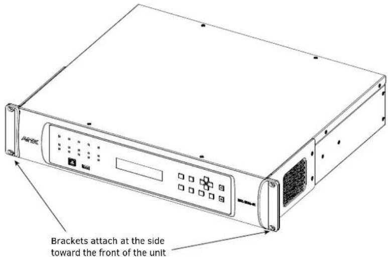
- Install the DVX in the mounting rack by using the mounting screws to affix the unit to the rack.
- Connect any applicable wires to the DVX.
CAUTION: DO NOT stand other units directly on top of the DVX when it is rack mounted, as this will place excessive strain on the mounting brackets.
Ventilation
ALWAYS ensure that the rack enclosure is adequately ventilated. Do not block any ventilation openings. Sufficient airflow must be achieved (by convection or forced-air cooling) to satisfy the ventilation requirements of all the items of equipment installed within the rack.
NOTE: The maximum operating ambient temperature is 40^ C ( 104^ F).
CAUTION: When installing equipment into a rack, distribute the units evenly. Otherwise, hazardous conditions may be created by an uneven weight distribution.
Reliable earthing (grounding) of rack-mounted equipment should be maintained.
The DVX should not be installed in enclosed spaces. It is recommended that you leave 1 RU of space above the DVX when you install it in a rack.
Wiring and Device Connectors
Overview
This chapter provides functional details for each item on the front and rear panel of the DVX. Wiring specifications are also provided, when applicable.
Front View
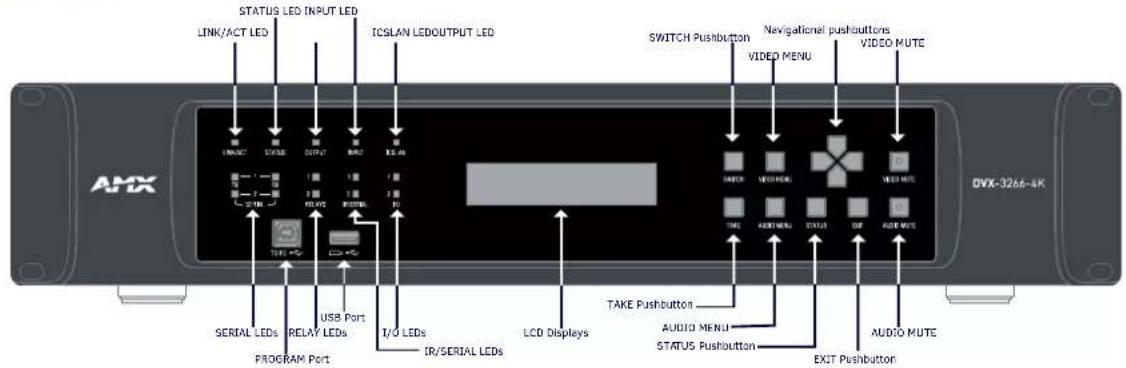
Fig 1 DVX-3266-4K&DVX-2265-4K Front panel
Rear View
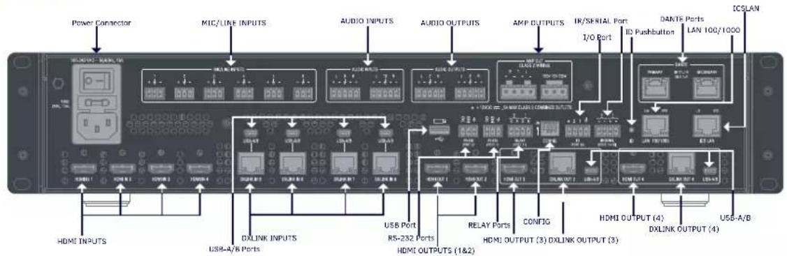
Fig 2 DVX-3266-4K Rear panel
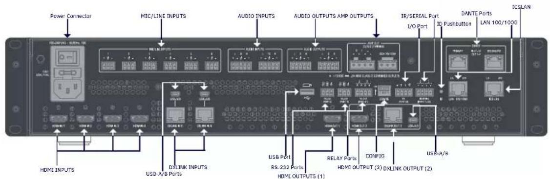
Fig 3 DVX-2265-4K Rear panel
Front Panel Controls and Indicators
The following sub-sections describe each component on the front panel of the DVX. Refer to FIG. 1 for the component layout of the front panel.
LEDs
The LEDs on the front panel indicate the communications status of several different connections. as described in the table below:
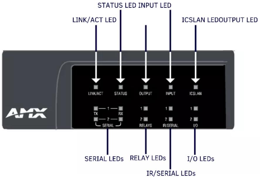
| Front Panel LEDs | ||
| Label | Color | Description |
| LINK/ACT | Green | On indicates that the Ethernet cables are connected and terminated correctly; Blinking indicates receiving Ethernet data packets. |
| STATUS | Green | Blinking indicates that the system is programmed and communicating properly |
| INPUT | Yellow | Blinking indicates that the Controller is receiving data. |
| OUTPUT | Red | Blinking indicates that the Controller is transmitting data. |
| ICSLAN | Red | Blinking when the category cable to port 1 is connected and terminated correctly. |
| SERIAL | Red/Yellow | Two LEDs indicate that the RS-232 port (1-2) is transmitting or receiving data. |
| RELAY | Red | On indicates that relay channels are active on Port (21). |
| IR/SERIAL | Red | On indicates that IR/SERIAL channels are transmitting control data on Port (11-12). |
| I/O | Yellow | On indicates that I/O channels are active on Port (22). |
LCD Displays
During normal operation, the 2 x 20 line LCD display indicates output volume information. The LCD backlight on the display turns off after 35 seconds of inactivity.
Main Amp Output
VOLUME: 20
SWITCH Pushbutton
Press the SWITCH pushbutton to access the SWITCH menu on the LCD display. Press this button to switch the audio, video, or both from any input to any output. Press the TAKE pushbutton to implement the switch.
TAKE Pushbutton
Press the TAKE pushbutton to implement an audio/video switch while you are in the Switch menu on the LCD display. When in an audio or video menu, press the TAKE pushbutton to cycle through audio and video inputs or outputs (depending on the menu.) This button does not access the menus or change the currently selected menu.
VIDEO MENU Pushbutton

Press the VIDEO MENU pushbutton to access the video options, displayed on the LCD display. There are two video menus (VIDEO OUTPUT and VIDEO INPUT) and both are accessible by using this button. Multiple presses cycle through the various VIDEO menus.
The Video menu enables you to see and adjust most parameters of the video input and output signals.
• Use the UP and DOWN navigational buttons to traverse the various configuration parameters.
• Use the LEFT and RIGHT navigational buttons to adjust the selected video parameter.
Adjustments take effect immediately (some parameter changes may exhibit a slight delay) and are saved when you advance to another option or exit the menu. The menu exits automatically after no user interaction on the front panel for 30 seconds.
See the Video Settings section for a listing of all available options and instructions on how to change the settings.
AUDIO MENU Pushbutton
Press the AUDIO MENU pushbutton to access the audio options, displayed on the LCD display. There are three audio menus (AUDIO OUTPUT, AUDIO INPUT, and MIC) and all are accessible by using this button. Multiple presses cycle through the various AUDIO menus.
The Audio menu enables you to see and adjust most parameters of the audio input and output signals.
• Use the UP and DOWN navigational buttons to traverse the various parameters.
• Use the LEFT and RIGHT navigational buttons to adjust the selected audio parameter.
Adjustments take effect immediately and are saved when you advance to another option or exit the menu. The menu exits automatically after no user interaction on the front panel for 30 seconds.
See the Audio Settings section on page 59 for a listing of all available options and instructions on how to change the settings.
Navigation Pushbuttons
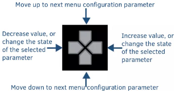
The four directional navigation buttons (Left/Right/Up/Down) enable you to navigate through and adjust the configurable parameters shown on the LCD display. The UP and DOWN navigation buttons are used to move between configurable parameters within a menu. Pressing UP takes you to the previous configuration parameter. Pressing DOWN takes you to the next configuration parameter. These buttons do not change the currently selected menu.
The LEFT and RIGHT navigation buttons are used to change the setting of the displayed parameter. If the parameter is read-only the value cannot change. Pressing LEFT decreases the value displayed if the setting is numeric or goes to the previously set item if the setting is a set selection. Pressing RIGHT increases the value displayed if the setting is numeric or goes to the next set item if the setting is a set selection. These buttons do not change the currently selected menu.
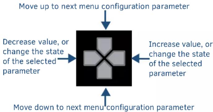
flowchart
graph TD
    A["Move up to next menu configuration parameter"] --> B["Decrease value, or change the state of the selected parameter"]
    B --> C["Increase value, or change the state of the selected parameter"]
    C --> D["Move down to next menu configuration parameter"]
STATUS Pushbutton

Press the STATUS pushbutton to access the STATUS menu on the LCD display.
The STATUS menu enables you to see status information such as IP address and installed firmware versions as well as adjust LCD and LED backlight intensity.
• Use the UP and DOWN navigational buttons to traverse the various options.
- Use the LEFT and RIGHT navigational buttons to adjust the selected LCD and LED backlight intensity (when selected).
Adjustments take effect immediately and are saved when you advance to another option or exit the menu. The menu exits automatically after no user interaction on the front panel for 30 seconds.
See the Status Menu section for a listing of all available options and instructions on how to change the settings.
EXIT Pushbutton
Press the EXIT pushbutton to exit any menu on the LCD display.
VIDEO/AUDIO MUTE Pushbuttons

- Press the VIDEO MUTE button to enable or disable video on all output displays.
- Press the AUDIO MUTE button to enable or disable audio for all audio outputs.
Program Port
The front panel of all models features one Type-B USB port for connecting the Controller to a PC via USB cable. The Program port uses a standard Type-A-to-Type-B USB cable to connect to a PC. When connected, you can view your DVX among the listed Controllers connected via USB in NetLinx Studio. See the Initial Configuration chapter in the NX-Series Controllers WebConsole and Programming Guide for more information.
USB Port
The front panel of all models features one Type-A USB port you can use to connect a mass storage device for loading .tkn files, reading or writing configuration files and log files, or updating the firmware on the unit.
NOTE: This USB port only supports a FAT32 file system.
This USB port uses standard USB cabling to connect to any mass storage or peripheral devices.
NOTE: USB hubs are not supported on this port.
Rear Panel Audio Inputs and Audio Outputs
The following sub-sections describe each component on the rear panel of the DVX. Refer to FIG. 2 & 3 on "Overview" section for the component layout of the rear panel.
AUDIO INPUTs
The AUDIO INPUTs connectors are 3.5 mm 5-position captive-wire terminals that can be wired for either balanced (differential) or unbalanced (single-ended) stereo audio. Since the DVX allows independent switching of video and audio, video and audio inputs of the same number do not have to be connected to the same source equipment.
These connectors feature the following specifications:
• Nominal input level: +4 dBu (1.228 Vrms) or -10 dBu (0.3262 Vrms) unbalanced
• Maximum input level: 2 Vrms
- Input impedance: >12k ohms unbalanced, >12k ohms balanced, DC coupled
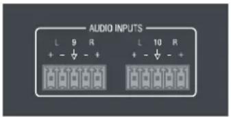
Source devices require either balanced (differential) or unbalanced (single-ended) connections. The following picture illustrates options for wiring between sources and input connectors. More than one option can be used in the same system.
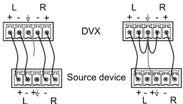
Balanced Wiring Unbalanced Wiring
The following picture provides details for wiring from an audio input to an unbalanced source device that has RCA connectors. Positive and ground wires connect to the source. You also can use an RCA Female to 5-Pin Phoenix Cable for this type of connection.
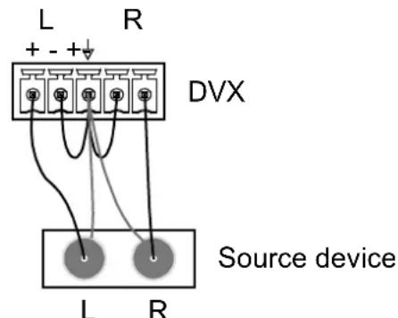
RCA Stereo Audio Source Wiring
RCA Stereo Audio Source Wiring
CAUTION: Do not connect the negative terminals to the source connector. Doing so can cause damage to your device.
HDMI INPUTs
The HDMI INPUT connectors on the rear panel routes digital audio (and video) from connected source input devices to the connected output devices. These inputs support the following audio formats:
Dolby TrueHD, Dolby Digital, DTS-HD, DTS, 2 CH L-PCM, 6 CH L-PCM, 8 CH L-PCM Dolby Digital and DTS support up to 48kHz, 5.1 channels.
For more information about these connectors, including wiring, see the "HDMI INPUTs" of Rear Panel Video Inputs and Outputs section.
The DVX models have DXLink input ports, which support embedded audio, in place of HDMI input ports. See the "DXLINK INPUTs" section for more information.
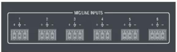
MIC/LINE INPUTs
Six 3.5mm 3-pin captive-wire MIC/LINE INPUT connectors allow up to six mono microphones to be connected to the DVX. Each microphone input supports balanced and unbalanced audio. Each input supports up to 48V of phantom power.
The following picture illustrates wiring connections between the DVX and a mono RCA output and an XLR output.
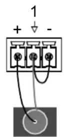
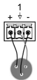
RCA output XLR output
AMP OUTPUTs
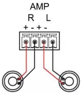
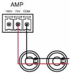
The amplifier in the DVX can be set to either low impedance or high impedance mode. The AMP OUT amplified audio output that you use will depend upon which mode is selected.
- The 4-position captive wire connector is used when in low impedance mode and provides amplified, variable, mono or stereo audio output.
- The 3-position captive wire connector is used when in high impedance mode and provides 70V or 100V mono amplified audio output. Connect a speaker to either the 70V or 100V terminal, but not both simultaneously.
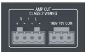
When using amplifier in low impedance mode, connect speakers to the AMP OUT output as displayed in the following picture:
When using the amplifier in high impedance mode, connect a speaker to either the 70V or 100V terminals as displayed in the following picture:
AUDIO OUTPUTs
The Line Level audio outputs provide balanced or unbalanced, mono or stereo line-level audio output.
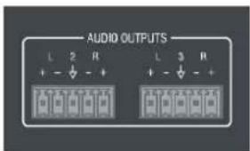
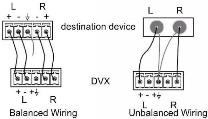
Destination devices require either balanced (differential) or unbalanced (single-ended) connections. The following picture illustrates options for wiring between output connectors and the destinations.
Destination devices require either balanced (differential) or unbalanced (single-ended) connections. The following picture illustrates options for wiring between output connectors and the destinations.
DANTE INPUTS/OUTPUTS
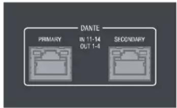
Two Dante ports on the rear panel are used to connect Dante/AES67 enabled audio devices to the DVX. It could be 4 x stereo digital audio inputs or 8 x Mono MIC inputs at required sampling rates: 48kHz and 24bit bit depth, and 4 x stereo digital audio outputs at required sampling rates: 48kHz and 24bit bit depth.
The following picture describes the blink activity for the LAN connector and cable.
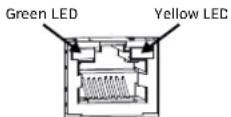
Green: Blinking when the audio data is being transmitted.
Yellow: Lights when the Dante enabled audio device is connected to the port.
Rear Panel Video Inputs and Outputs
The following sub-sections describe each component on the rear panel of the DVX. All digital inputs and outputs on the DVX support HDCP2.2. Refer to Fig 2 & 3 of "Overview" section for the component layout of the rear panel.
HDMI INPUTs
The HDMI INPUT connectors on the rear panel are used to connect source input devices to the DVX. The DVX routes digital video and audio from connected source input devices to the connected output devices. These ports support HDMI (with 3D and Deep Color) and HDCP 2.2.
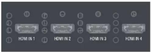
These numbered inputs correspond to the input port number of the video signal when making a switch or adjusting video input parameters.
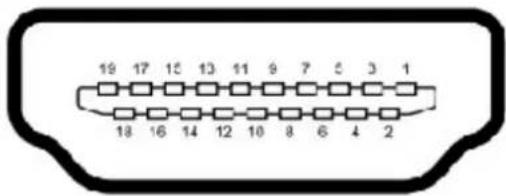
The following table describes the pinout configuration of the HDMI INPUTS connectors:
| HDMI INPUT Connectors – Pins and Signals | |||
| Pin | Signal | Pin | Signal |
| 1 TMDS Data 2+ 11 TMDS Clock | Shield | ||
| 2 TMDS Data 2 Shield 12 TMDS Clock- | |||
| 3 TMDS Data 2- 13 CEC | |||
| 4 | TMDS Data 1+ | 14 | Reserved, HEC Data |
| 5 TMDS Data 1 Shield | 15 | SCL | |
| 6 TMDS Data 1- | 16 | SDA | |
| 7 | TMDS Data 0+ | 17 | DDC/CEC/HEC Ground |
| 8 | TMDS Data 0 Shield | 18 | +5V Power (max 50mA) |
| 9 TMDS Data 0- 19 Hot Plug Detect, HEC Data+ | |||
| 10 TMDS Clock+ 20 | |||
DXLINK INPUTs
Four DXLink (RJ-45) connectors on DVX-3266-4K and two DXLink (RJ-45) connectors transport digital video, embedded audio, Ethernet, and bi-directional control, USB and power over twisted pair cable to DXLink devices, including digitally transcoded analog video signals. Both inputs support HDCP 2.2.
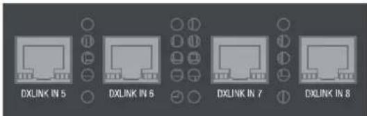
See the Important Twisted Pair Cabling Requirements and Recommendations section for information about cable requirements for these ports.
DXLINK/HDMI OUTPUTs
The following sections provide details on the video outputs for the 3266 and 2265 DVX models.
DVX-3266-4K Video Outputs
The DXLINK/HDMI OUTPUTS include 2 different types of connectors:
• 4 HDMI Output connectors (1-4) each provide digital HDMI audio and video output.
2 DXLink Twisted Pair outputs (3, 4) mirror HDMI outputs 3 and 4. They provide digital video, audio, Ethernet, bi-directional control, USB, and power over Category Cable to DXLink Receivers.
See the "Important Twisted Pair Cabling Requirements and Recommendations" section below for information about cable requirements.
NOTE: On Video outputs 3 and 4, if you are using both DXLink and HDMI outputs, it is recommended that they have the same native resolution. In this situation, the EDID from the HDMI display is used to determine the SmartScale resolution and timing.

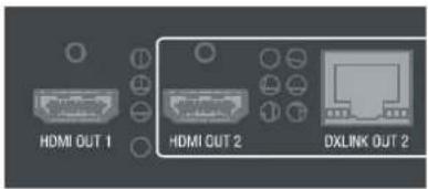
DVX-2265-4K Video Outputs
The VIDEO OUTPUTS include 2 different types of connectors:
• 2 HDMI Output connectors (1-2) each provide digital HDMI audio and video output.
- 1 DXLink Twisted Pair output (2) mirrors HDMI output 2. It provides digital video, embedded audio, Ethernet, bi-directional control, USB and power over Category Cable to DXLink Receivers.
See the "Important Twisted Pair Cabling Requirements and Recommendations" section information about cable requirements.
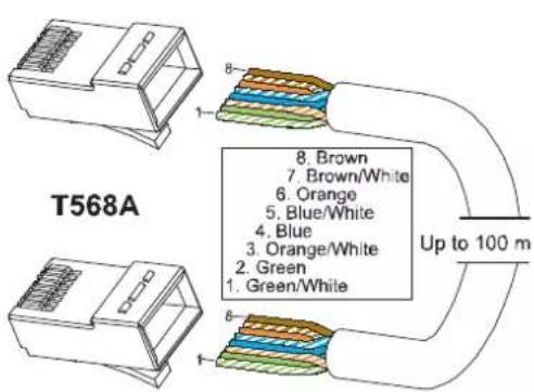
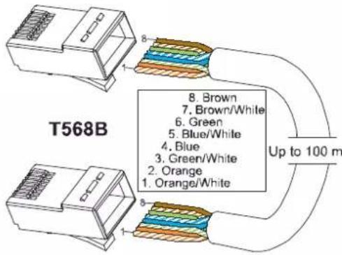
Twisted Pair Cable Pinouts
AMX supports both the T568A and T568B pinout specifications for termination of the twisted pair cable used between the DVX and the DXLink receiver.
Important Twisted Pair Cabling Requirements and Recommendations
The following requirements and recommendations apply to cabling DXLink (RJ-45) connectors:
• DXLink cable runs require shielded category cable (STP) of Cat6 (or better).
- DXLink twisted pair cable runs for DXLink equipment shall only be run within a common building. *
- DXLink delivers 10.2 Gb/s throughput over shielded category cable. Based on this bandwidth requirement, we recommend following industry standard practices designed for 10 Gigabit Ethernet when designing and installing the cable infrastructure.
- The cables should be no longer than necessary to reach the end-points. We recommend terminating the cable to the actual distance required rather than leaving any excess cable in a service loop.
For more details and helpful cabling information, reference the white paper titled "Cabling for Success with DXLink" available at www.amx.com or contact your AMX representative.
* "Common building" is defined as: Where the walls of the structure(s) are physically connected and the structure(s) share a single ground reference.
Rear Panel Control and Power
RS232 Ports
The RS-232 ports (Port 1-2 on the DVX) are 3-pin 3.5 mm mini-Phoenix (male) connectors used for connecting A/V sources and displays. These ports support most standard RS-232 communication protocols for data transmission.
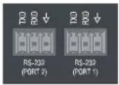
The following table lists the pinouts for RS232 ports.
| RS232 Port Pinouts | |
| Pin 1 GND | |
| Pin 2 RXD | |
| Pin 3 TXD | |
In the above table, pin 1 is located on the right side of the port, and the pinouts count up to the left.
RELAY Ports
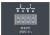
The relay ports (port 21 on the DVX) are 4-pin 3.5 mm mini-Phoenix (male) connectors used for connecting external relay devices.
When a relay is "OFF", terminals A and B are open circuit. When a relay is "ON", terminals A and B are shorted together.
I/O Ports
The I/O ports (port 22 on the DVX) are 4-pin 3.5 mm mini-Phoenix (male) connectors used for connecting logic-level outputs. The I/O port responds to either switch closures, voltage level (high/low) changes, or it can be used for logic-level outputs. Each port is capable of being used as an input or an output.
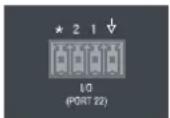
• A contact closure between the GND and an I/O port is detected as a Push.
- When used for voltage inputs, the I/O port detects a low signal (0 - 1.5 VDC) as a Push, and a high signal (3.5 - 5 VDC) as a Release. (This I/O port uses 5V logic but can handle up to 12V without harm).
- When used for outputs, the I/O port acts as a switch to GND and is rated for 200mA @ 12 VDC.
• The PWR pin provides +12 VDC @ 200 mA output.
• The GND connector is a common ground and is shared by all I/O ports.
• The input impedance on the I/O port is 22k.
| I/O Port Pinouts | ||
| Pin | Signal | Function |
| Pin 1 GND Signal GND | ||
| Pin 2 | I/O 1 | Input/Output |
| Pin 3 | I/O 2 | Input/Output |
| Pin 4 12 VDC | PWR | |
In the above table, pin 1 is located on the right side of the port, and the pinouts count up to the left.
IR/SERIAL Port: Connection and Wiring
The IR/SERIAL port (port 11-12) provides IR transmit/one-way serial connections that support high-frequency carriers up to 1.142 MHz. You can simultaneously generate up to two IR/Serial data signals on the DVX-3266-4K and DVX-2265-4K.
These ports accept an IR Emitter that mounts onto the device's IR window, or a custom cable that connects to a device's control jack. You can also connect a data 0 - 5 VDC device to these ports.
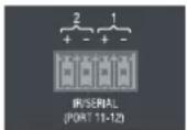
NOTE: The maximum baud rate for ports using DATA mode is 19200. Also, DATA mode works best when using a short cable length (< 10 feet).
NOTE: For each data signal, the negative (-) terminal is for Signal GND, and the positive (+) terminal is for IR/Serial data.
Configuration DIP Switch
DVX-3266-4K and DVX-2265-4K have a configuration DIP switch which allows for certain operations to occur during boot-time. The DIP switch positions are assigned as follows:
Switch for Program Run Disable
You can use the Configuration DIP switch to set the on-board Controller to Program Run Disable (PRD) mode. PRD mode prevents the NetLinx program stored in the on-board Controller from running when you power up the Integrated Controller. You should only use PRD mode when you suspect the resident NetLinx program is causing inadvertent communication and/or control problems.
If necessary, place the on-board Controller in PRD mode and use the NetLinx Studio program to resolve the communication and/or control problems with the resident NetLinx program. Then download the new NetLinx program and try again.
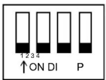
Default Mode
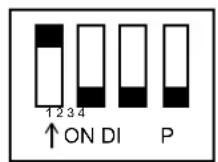
PRD Mode
NOTE: Consider equating PRD Mode to a PC's SAFE Mode setting. With PRD mode, you can continue to power a unit, update the firmware, and download a new program while circumventing any problems with a currently downloaded program. You must power cycle the unit after activating/deactivating PRD mode on Program Port DIP switch #1.
ICS LAN Port
All DVX models have two types of Ethernet ports: LAN and ICSLAN. The LAN port is used to connect the Controller to an external network, and the ICSLAN ports are used to connect to other AMX equipment or third-party A/V equipment. The ICSLAN ports on all models provide Ethernet Communication to connected AMX Ethernet
Equipment in a way that is isolated from the primary LAN connection.
The ICSLAN port is a 10/100 Port RJ-45 connector and Auto MDI/MDI-X enabled. Each model of DVX features one port. The port support IPv4 and IPv6 networks, as well as HTTP, HTTPS, Telnet, and FTP.
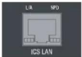
The following picture describes the blink activity for the LAN connector and cable.
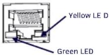
- L/A – Green LED: Lights when link is successful; blinking when the data packages are being transmitted.
- SPD – Yellow LED: Lights when the connector speed is 100Mbps; off when the connector speed is 10Mbps.
The ICSLAN port gets its IP addresses in one or more of the following ways:
- IPv4 - Static assignment of the subnetwork address by the user
• IPv6 - Link local address
Using the ICSLAN Network
The default IP address for the ICSLAN network is 198.18.0.1 with a subnet mask of 255.255.0.0.
It is important that the ICSLAN and LAN subnets do not overlap. If the LAN port is configured such that its address space overlaps with the ICSLAN network, the ICSLAN network will be DISABLED.
NOTE: Typically, the DVX communicates with an A/V switcher via ICSLAN. Since the A/V switcher has a static IP address on the ICSLAN network, and you cannot change the IP address on the switcher, you cannot change the 198.18 subnet information on the DVX platform of processors. You can only change the Host name and DHCP server settings.
DHCP Server
The ICSLAN port has a built-in DHCP server. This DHCP server is enabled by default and will serve IP addresses to any connected devices set to DHCP mode.
The DHCP server can be disabled from telnet with the command:
SET ICSLAN
The DHCP address range is fixed. The server will provide addresses in the range x.x.0.2 through x.x.63.255.
Devices using static IP addresses on the ICSLAN network should be set within the reserved static IP address range of x.x.64.1 to x.x.255.255.
Opening LAN and ICSLAN Sockets from Code
When opening sockets from NetLinx or Java code there is no mechanism to indicate which network to use. The Controller will open the socket on whichever network has an IP subnet that matches the address provided in the command to open the socket. There is no indication which network was used, only whether the socket was created successfully.
USB Port
All DVX models feature one Type-A USB port you can use to connect a mass storage device for loading .jar files and IR data files (.irl), reading or writing configuration files and log files, or updating the firmware on the unit.
NOTE: This USB port only supports a FAT32 file system.
This USB port uses standard USB cabling to connect to any mass storage or peripheral devices.
NOTE: USB hubs are not supported on this port.
USB A/B Ports
The USB A/B Ports are USB-Mini-AB multi-use connectors to allow the connected endpoints device to pass through USB Host/Device control over the corresponding HDBT connection. These USB A/B ports support USB 2.0.
DVX-3266-4K features six USB A/B ports and DVX-2265-4K features three USB A/B ports.

ID Pushbutton
All DVX models feature an ID pushbutton which you can use to toggle between static and dynamic IP addressing. You can also use the pushbutton to reset the default settings on the Controller or restore the Controller to its factory firmware image.
1. Switching to Static or Dynamic IP Addressing
To toggle between static or dynamic IP addressing, the Controller cannot be currently booting or it must be in ID Mode. If these conditions are met, holding the ID pushbutton for 10 seconds changes the current IP addressing mode.
2. Restoring the Controller Settings to the Factory Defaults
To restore the Controller settings to the factory defaults, power off the DVX, press and hold the ID button, then power on the DVX and continue to hold ID pushbutton for a full 10 seconds. Then let go of the ID button and the Controller will reset to its default parameters. This includes resetting the static IP address to its default and deleting the NetLinx program. It will take a few minutes then come back online.
CAUTION: Pressing the ID pushbutton for 20 seconds restores the factory firmware image on the controller. Do not press the pushbutton significantly longer than the necessary 10 seconds if you only want to restore the default settings on the controller.
3. Restoring the Controller's Factory Firmware Image
To restore the Controller's factory firmware image, the Controller must currently be booting and you must press the ID pushbutton for 20 seconds. This also deletes all code and IRL files.
LAN 100/1000
All DVX models feature a LAN 100/1000 port to provide 100/1000 Mbps communication via Category cable. This is an Auto MDI/MDI-X enabled port, which allows you to use either straight-through or crossover Ethernet cables. The port support IPv4 and IPv6 networks, as well as HTTP, HTTPS, Telnet, and FTP.
The LAN port automatically negotiates the connection speed (100 Mbps or 1000 Mbps), and whether to use half duplex or full duplex mode.
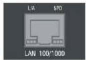
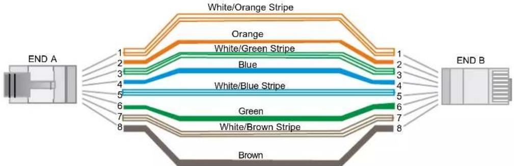
See the Pinouts and signals for the LAN connector and cable in the following picture.
flowchart
graph LR
    A["END A"] --> B["1"]
    A --> C["2"]
    A --> D["3"]
    A --> E["4"]
    A --> F["5"]
    A --> G["6"]
    A --> H["7"]
    A --> I["8"]
    J["END B"] --> K["1"]
    J --> L["2"]
    J --> M["3"]
    J --> N["4"]
    J --> O["5"]
    J --> P["6"]
    J --> Q["7"]
    J --> R["8"]
    S["White/Orange Stripe"] --> T["1"]
    S --> U["2"]
    S --> V["3"]
    S --> W["4"]
    S --> X["5"]
    S --> Y["6"]
    S --> Z["7"]
    S --> AA["8"]
The following picture describes the blink activity for the LAN connector and cable.
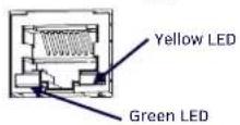
• L/A--Green LED: Lights when link is successful; blinking when the data packages are being transmitted.
- SPD—Yellow LED: Lights when the connector speed is 1000Mbps; off when the connector speed is 10Mbps/100Mbps.
The LAN port gets its IP address(es) in one or more of the following ways:
IPv4
• Static assignment by the user
• Dynamic assignment by an IPv4 DHCP server (default)
- Link local as a fall back when configured for DHCP but unable to successfully obtain address
IPv6
- Link local address
- Prefix(es) assigned by a router
Power Connector
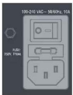
CAUTION: This unit should only have one source of incoming power.
Using more than one source of power to the Controller can result in damage to the internal components and a possible burn out.
Apply power to the unit only after installation is complete.
Audio/Video Configurations
Overview
You can access the configuration settings for the DVX by using one of the following methods:
• Using the front panel buttons
• Using a Web browser
Using the Front Panel Buttons
You can access the configuration settings for the All-In-One Presentation Switcher by using the VIDEO MENU, AUDIO MENU, SWITCH, and STATUS buttons on the front panel of the DVX. Pressing any button opens its respective menu on the LCD display on the front panel. The LCD backlight on the display turns off after 35 seconds of inactivity.
Press the TAKE pushbutton to implement an audio/video switch while you are in the Switch menu on the LCD display. If you are in any menu other than Switch, press the button to cycle through audio and/or video inputs.
Use the Navigational buttons to traverse the available configuration parameters and change their settings. FIG. 66 displays the navigational function of each button.
flowchart
graph TD
    A["Move up to next menu configuration parameter"] --> B["Decrease value, or change the state of the selected parameter"]
    B --> C["Increase value, or change the state of the selected parameter"]
    C --> D["Move down to next menu configuration parameter"]
Video Settings
The following table lists the Video Output menu options available by pressing the VIDEO MENU button.
| Video Output Menu Options | |
| Video OutputSelect | Use the left and right navigational buttons to manually select which video output you want to use. You can choose from 1, 2, 3 (for DVX-3266 only), 4 (for DVX-3266 only), or ALL. |
| Scaling | Use the left and right navigational buttons to toggle whether you want to scale the output image. You can choose from AUTO, MANUAL, and BYPASS. The default setting is AUTO. |
| Resolution | Use the left and right navigational buttons to manually select the desired resolution and refresh rate of the selected output. For a complete list of output resolutions, see the “Specification” section.Changing the output resolution automatically switches the scaling mode to MANUAL. |
| AR | Use the left and right navigation buttons to select how video inputs should be displayed when the input and output aspect ratio do not match. You can choose from the following options:MAINTAIN: Maintains the input aspect ratio while filling the screen either vertically or horizontally. Black bars may appear above and below or to the left and right of the image.• STRETCH: Ignores the input aspect ratio and stretches the image to fill the screen in all directions.The default setting is STRETCH. |
| Blank Screen | Use the left and right navigational buttons to select the color of the blank screen on the output. You can choose from Black or Blue. The default setting is Black.NOTE: If you have uploaded a logo to display on the output, you can also select the logo from this option. Logo images must be at least 36x36 pixels in size. |
| OSD | Use the left and right navigational buttons to toggle whether you want the OSD overlay to be turned on or off.You can choose from Enabled or Disabled. When enabled, the input name and resolution displays in a small box in the upper left-hand corner of the screen whenever you select a new input source.The location of the input name and resolution can be changed using the OSD Position option. The default setting is Disabled. |
| OSD Pos | Use the left and right navigational buttons to select the on-screen display's relative position so it is unobtrusive to video. You can choose from Top Left, Top Right, Bottom Left, and Bottom Right. The default setting is Top Left. |
| OSD Color | Use the left and right navigational buttons to select the background color for the on-screen display. You can choose from Black, White, Yellow, or Blue. The default setting is Black. |
| Source (Output Video Adjust) | |
| Brightness | Use the left and right navigational buttons to alter the brightness level adjustment applied to the selected output.You can set the brightness level from 0-100. The default setting is 50. |
| Contrast | Use the left and right navigational buttons to alter the contrast level adjustment applied to the selected output. You can set the contrast level from 0-100. The default setting is 50. |
| Freeze | Use the left and right navigational buttons to toggle whether you want the current image to freeze and remain on the screen. You can choose from On or Off. The default setting is Off. |
| Revert to Default | Use the left and right navigational buttons to indicate that you want to return all video options to their default settings. When the display indicates to "Press TAKE for YES", pressing the Take button reverts all configurable output image adjustments to their default values. |
The following table lists the Video Input menu options available by pressing the VIDEO MENU button twice from the main volume screen.
| Video Input Menu Options | |
| Input Select | Use the left and right navigational buttons to manually select which video input you want to use. You can choose any available input from 1-8. |
| Status | Use this option to view the status of the selected input. The status can read NO SIGNAL, SIGNAL OK, and UNKNOWN. This is a read-only field and pressing the left/right arrow keys will have no effect. |
| EDID | Use the left and right navigational buttons to indicate the type of EDID data to be sent to the source or which output's EDID you would like to mirror to that source. You canchoose All resolutions, Wide-Screen resolutions,Full-Screen resolutions, or to mirror the EDID from any of the HDMI outputs. |
| EDID Update | When the EDID is set to mirror one of the outputs, use the left and right navigational buttons to indicate whether you want the EDID going to the source to update anytime the output EDID changes or only when an update is requested manually. You can choose from AUTO and OFF. The default setting is AUTO. |
| Source (Input Video Adjust)NOTE: The following input video adjustments have no effect on the display of the internally generated test patterns. | |
| Revert to Default | Use the left and right navigational buttons to indicate that you want to return all video options to their default settings. |
Changing the Video Output Resolution
Perform these steps to change the video output resolution:
- Press the VIDEO MENU button on the front panel of the DVX to open the Video Output menu.
- Press the left and right navigation buttons to select the output to change.
- Press the down navigational button until the Resolution option appears.
- Use the left and right navigational buttons to locate the appropriate output resolution and refresh rate. You can also choose Auto to automatically detect the resolution and refresh rate.
Changing the Output Aspect Ratio
Perform these steps to change the output aspect ratio:
- Press the VIDEO MENU button on the front panel of the DVX to open the Video Output menu.
- Press the left and right navigation buttons to select the output to change.
- Press the down navigational button until the Aspect Ratio option appears.
- Use the left and right navigational buttons to locate the appropriate aspect ratio
Audio Settings
The following tables list the audio options available on the LCD display by pressing the AUDIO MENU button on the front panel:
| Audio Output Menu Options | |
| Audio Group Select | Use the left and right navigational buttons to manually select which audio group you want to use. You can choose from 1, 2, 3, 4 or ALL. |
| Audio Group Volume | Use the left and right navigational buttons to set the volume of the selected audio group. You can set the volume from 0 to 100. The default setting is 20. |
| Audio Group EQ Preset | Use the left and right navigational buttons to select a group of preset equalizer settings. You can choose from Voice, Movie, Music, and Off. |
| Audio Group Balance | Use the left and right navigational buttons to adjust the balance level of the selected audio group. You can set the balance level from -20 to +20. The default value is 0. |
| Audio Group Format | Use the left and right navigational buttons to change the audio format of the selected audio group. You can set the audio format to Stereo or Mono. The default setting is Stereo. |
| Audio Group Src Mix | Use the left and right navigational buttons to set the mix level of the audio inputsource in the overall mix. You can set the mix level from -100 to 0. The default setting is 0. |
| Audio Group Mic Mix | Press TAKE button to enter the submenus: Audio Group Mic (1-14) Mix settings. Use the left and right navigational buttons to set the mix level of Audio output Mic (1-14) in the overall mix. You can set the mix level from 0 -100 to 0. The default setting is 0. |
| Audio Group HDMI EQ | Use the left and right navigational buttons to toggle whether the equalizer settings for the selected analog output should be applied to the HDMI output. You can choose from On or Off. The default value is Off. |
| Audio Group Max Volume | Use the left and right navigational buttons to adjust the maximum volume of the audio Group. You can set the maximum volume from 0 to 100 in increments of 5. The default value is 100. |
| Audio Group Min Volume | Use the left and right navigational buttons to adjust the minimum volume of the audio Group. You can set the minimum volume from 0 to 100 in increments of 5. The default value is 0. |
| Audio Group Delay (ms) | Use the left and right navigational buttons to set the number of milliseconds to delay the audio. The default value is 32. |
| Test Tone | Use the left and right navigational buttons to select an internally generated audible tone. The selected tone overrides any input source selection. Selecting 'Off' removes the override, allowing you to hear audio from the selected source. You can choose from Off, 60Hz, 250Hz, 400Hz, 1kHz, 3kHz, 5kHz, 10kHz, Pink Noise, and White Noise. |
| Ducking | Use the left and right navigational buttons to set the ducking level of the audio output. You can choose from Off, Low, Med, High, and Custom. All detailed parameter adjustments for the Custom setting can be made from the web user interface. See the Using a Web Browser section on page 63 for more information. The default setting is Off. |
| Mic Threshold | Click “TAKE” button to enter the submenu. Use up and down navigational buttons to select mixed up microphone threshold or priority microphone threshold, and use the left and right navigational buttons to set the threshold value of the ducker for selected microphone threshold. You can set the threshold level from -60 to 0. |
| Mic Priority | Use the left and right navigational buttons to indicate Which of the active mic inputs has priority. You can choose any enabled analog or Dante microphone input or None to disable any mic priority. |
| Revert to Default | Use the left and right navigational buttons to indicate that you want to return all audio group options to their default settings. |
| Audio Input Menu Options | |
| Audio Input Select | Use the left and right navigational buttons to manually select which audio input you want to use. You can choose from any of the available audio inputs. |
| Gain | Use the left and right navigational buttons to adjust the gain/attention level of the audio input. You can set the gain from -24 to +24dB in 1dB increments. The default setting is 0. |
| Format | Use the left and right navigational buttons to toggle the analog format for theaudio input. You can choose from Stereo or Mono. The default setting is Stereo. |
| Compression | Use the left and right navigational buttons to adjust the compression level of the selected audio input. You can choose from Off, Low, Medium, High, and Custom. The default value is Off. |
| Revert to Default | Use the left and right navigational buttons to indicate that you want to return all audio input options to their default settings. |
| MIC Input Menu Options | |
| Mic Input Select | Use the left and right navigational buttons to manually select which microphone input you want to use. |
| Enable Use the left and right | navigational buttons to toggle whether the selected microphone is active. You can choose from Off or On. The default setting is Off. |
| Preamp Gain | Use the left and right navigational buttons to adjust the preamp gain level of the microphone input. You can set the gain from 0 to +60dB in 3dB increments. The default setting is 0. |
| Gain | Use the left and right navigational buttons to adjust the gain/attention level of the microphone input. You can set the gain from -24 to +24dB in 1dB increments. The default setting is 0. |
| Compression | Use the left and right navigational buttons to adjust the compression level of the selected microphone. You can choose from Off, Low, Medium, High, and Custom. The default value is Off. |
| Limiter | Use the left and right navigational buttons to adjust the limiter function which suppresses loud noise bursts from dropping the mic and helps avoid feedback noise. You can choose from Off, Low, Medium, High, and Custom. The default setting is Off. |
| Gating | Use the left and right navigational buttons to adjust the noise gate which filters background noise. You can choose from Off, Low, Medium, High, and Custom. The default setting is Off. |
| Phantom Power | Use the left and right navigational buttons to turn on or turn off phantom power for the selected microphone.You can set the Phantom Power to On or Off. The default setting is Off. |
| Revert to Default | Use the left and right navigational buttons to indicate that you want to return all microphone options to their default settings. |
| Dante Input Menu Options | |
| Dante Input Select | Use the left and right navigational buttons to manually select which Dante input channel you want to use. You can choose from any of the available Dante inputs (1/2, 3/4, 5/6, 7/8). |
| Dante Input Mode | Use the left and right navigational buttons to manually select stereo audio or Mono mic individually. Only those channels set to Mono Microphone will be available for mixing and only those set to stereo input will be available for switching. |
Selecting an Audio Test Tone
Selecting a test tone for your input source can help determine if you have your audio devices connected correctly. Perform these steps to select a test tone:
- Press the AUDIO MENU button on the front panel of the DVX.
- Press the left and right navigation buttons to select the output on which to play the test tone.
- Press the down navigational button until the Test Tone option appears.
- Use the left and right navigational buttons to select an appropriate audio test tone.
Switch Menu
Press the SWITCH button to access the Switch menu for switching between the available audio and video devices. Use the UP and DOWN navigational buttons to scroll through the menu options. Use the RIGHT and LEFT navigational buttons to select the desired input and output. Press the TAKE button to execute the switch.
| Switch Menu | |
| Select A+V Input | Use the SWITCH button to cycle through the available inputs. This option is only available if you select Both on the Switch Level option. |
| Select A+V Output | Use the SWITCH button to cycle through the available outputs. This option is only available if you select Both on the Switch Level option. |
| Select Video Input | Use the SWITCH button to cycle through the available video inputs. This option is only available if you select Video on the Switch Level option. |
| Select Video Output | Use the SWITCH button to cycle through the available video outputs. This option is only available if you select Video on the Switch Level option. |
| Select Audio Input | Use the SWITCH button to cycle through the available audio inputs. This option is only available if you select Audio on the Switch Level option. |
| Select Audio Output | Use the SWITCH button to cycle through the available audio outputs. This option is only available if you select Audio on the Switch Level option. |
Status Menu
Press the STATUS button to access the Status menu and display system information on the LCD display. Use the UP and DOWN navigational buttons to scroll through the menu options. These options are view-only.
| Status Menu | |
| Vid Status | Displays which video input is associated with each output. |
| Aud Status | Displays which audio input is associated with each output. |
| Mic Status | Displays the active status of each microphone output. |
| System Number: | Displays the system number of the All-In-One Presentation Switcher. |
| Serial Number: | Displays the serial number of the All-In-One Presentation Switcher. |
| MAC Address: | Displays the MAC address of the All-In-One Presentation Switcher. |
| IP Address: | Displays the IP address of the network. |
| IP Address Type: | Displays whether the IP address is static or DHCP. |
| Subnet Mask: | Displays the subnet mask of the network. |
| Gateway: | Displays the gateway address of the network. |
| Hostname: | Displays the hostname of the device. |
| DNS Address: | Displays the IP or DNS address of the device. |
| Controller Version: | Displays the version number of the firmware the controller is using. |
| Switcher Version: | Displays the version number of the firmware the switcher is using. |
| Device Version: | Displays the version number of the firmware the device is using. |
| Fan: | Displays the speed in Revolutions per Minute (RPM) for each fan. |
| Temperature: | Displays the temperature of the device in degrees Celsius (C). |
| Enter Standby Mode: | Use the left and right buttons to toggle whether Standby Mode is active. Select either Off or On. The default setting is Off. |
DVX WebConsole
The DVX features an on-board WebConsole that allows you to configure the device and make various adjustments to audio/video and system settings. The WebConsole is accessed via a web browser on a PC that has network access to the DVX.
The DVX WebConsole can be divided into two primary parts:
• Audio/Video Switcher Configuration Settings
- Status
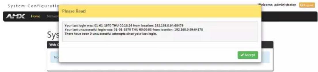
Accessing the WebConsole
From any PC that has access to the LAN that the target Controller resides on:
- Open a web browser and type the IP Address of the target Controller in the Address Bar.
- Press Enter to access WebConsole for that Controller. The initial view is the Web Control page.
Copyright © 2006-2021 AMX, LLC

When using the Microsoft Internet Explorer browser in Windows 8, you may not be able to login and connect to the Controller via the WebConsole. If you cannot login and connect, try any of the following options:
- Shift + Right-click Internet Explorer icon and select Run as administrator.
- Select Internet Options | Advanced | Security Settings, and check Enable Enhanced Protection Mode. A Windows 8 restart will be required.
- Use the Controller's Hostname instead of its IP numeric address to enter the URL (e.g.: http://AMXM98A1A2B rather than http://192.168.1.123).
• Use a non-Windows 8 device if Internet Explorer 10+ is required.
Controller Configuration Options
The DVX provides the same set of configuration pages that are available to the NX-Series Controllers.
NOTE: All NX-Series NetLinx Controllers share a common WebConsole, as described in the NetLinx Integrated Controllers WebConsole & Programming Guide (available at www.amx.com).
WebConsole - System Configuration
The DVX (and all other NetLinx Controllers) features a built-in WebConsole that allows you to make various configuration settings via a web browser on any PC that has access to the Controller.
The WebConsole consists of a series of web pages that are collectively called the "Controller Configuration Manager"
The WebConsole is divided into six primary sections, indicated by six control buttons across the top of the main page.
System Configuration

- Home: This option appears when you access the System Configuration page. Use these options to view any connected device or access a module.
- Network: Click to access the Network Settings for the Controller. The options on these pages enable you to view and modify the IPv4 and IPv6 network settings and the clock settings for the system.
- Security: Click to access the System Security page. The options in this page allow you to configure various aspects of NetLinx System and Security on the Controller, including network configuration and creating users and roles.
- System: Click to access the System Details page. The options on this page allow you to view and configure various aspects of the NetLinx System.
- Modules: Click to access several different device-related pages.
- Switcher: Click to access the Enova Switcher Configuration page.
WebConsole User Interface - Additional Documentation
For a full description of all System Configuration pages, refer to the NX-Series Controllers WebConsole & Programming Guide, available at www.amx.com.
Using a Web Browser
You can access the configuration settings for the All-In-One Presentation Switcher by using the latest, industry-accepted version of HTML5 web browsers. If a browser is inconsistent, upgrade or try a different browser. The system configuration pages are available by entering the IP address of the NetLinx Controller into the location bar of your web browser. Entering the DVX's IP address into your web browser opens the Main Web Control page.
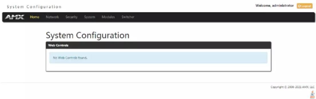
Perform these steps to access the configuration settings:
- Open a web browser.
-
Enter the IP address of the All-In-One Presentation Switcher in the location bar of the web browser. (If you do not know your switcher's IP address, see the "Locating the IP Address of the DVX" section.) The Main Web Control page opens.
-
Click the Switcher tab to open the Enova DVX Setup page.
If a web browser is not available, the All-In-One Presentation Switcher's front panel and NetLinx commands provide equivalent controls for audio/video configuration. See the "Front Panel Controls and Indicators" section for more information.
Locating the IP Address of the DVX
You can locate the IP address of the DVX by using the buttons on the front panel of the unit. The IP address appears on the LCD display on the front panel of the DVX. Perform these steps to locate the IP address of the unit:
- Press the STATUS button on the front panel of the unit. The Status menu appears on the LCD display.
- Use the UP and DOWN navigational arrow buttons to navigate through the options until you locate the All-In-One Presentation Switcher's IP address. Note the IP address for future reference.
NOTE: You can use the Status Menu to verify current TCP/IP settings using the UP and DOWN navigational buttons.
Default User Name and Password
The default Username is "administrator", and the default password is "password".
Take the WebConsole of DVX-3266-4K as an example to introduce the following WebConsole pages.
General Options
The WebConsole Configuration page contains settings that are accessible from each tab indicates the universally accessible options available on the web pages.
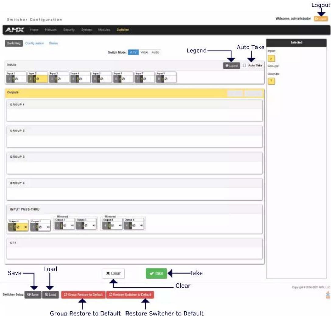
The following table lists the general options for the WebConsole Configuration page:
| General Settings | |
| Logout | Exit the configuration page and return to the Login page. |
| Legend | Click the button to enter a help page. Shows the explanations about colors of the Input and output buttons on this page. (In Switching/Configuration Pages) |
| Auto Take | Click to toggle whether Auto Take when the selection operation is completed. (In Switching/Configuration Pages) |
| Save | Click to save the current Settings on WebConsole as a .xdv file to local PC. |
| Load | Click to load the saved Setting .xdv file from local PC. |
| Group Restore to Default | Click the button to enter Warning window, select A/V group (from Video, Audio, Video and Audio) and I/O group (from Inputs, Outputs, Inputs and Outputs) to restore the groups to default settings in Warning window. For example, select Video from A/V group and select Inputs from I/O group in Warning window, all video inputs will be restored to factory defaults. |
| Restore Switcher to Default | Click to restore the switcher to factory default settings. Click “Yes” in the Warning window, it will take about 2 minutes to restore Switcher configuration values back to default. |
| Clear | Click to clear all the selections. (In Switching/Configuration Pages) |
| Take | Click to take effect. (In Switching/Configuration Pages) |
Switching Options
The Switching tab enables you to set A/V, Video and Audio Inputs for Outputs.
A/V Switch Mode
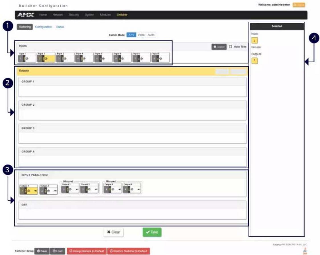
1- Inputs: This area enables you to select an Audio/Video input to be switched to the selected A/V output.
NOTE: The A/V switch mode includes 4 HDMI Inputs and 4 DXLINK Inputs for selecting.
2- Groups: Shows the output groups.
Select All: Use the menu to select all inputs to the selected outputs.
Deselect All: Use the menu to cancel selecting all inputs to the selected outputs.
3- Input PASS THRU: This area enables you to select an Audio/Video output.
NOTE: The A/V switch mode includes 4 HDMI outputs and 2 DXLINK outputs for selecting. The 2 DXLINK outputs are mirrored with HDMI output 3 and 4 separately.
4- Selected: Shows the current selection.
Video Switch Mode
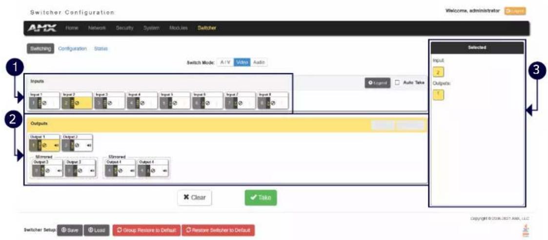
1- Inputs: This area enables you to select a Video input to be switched to the selected video output.
NOTE: The Video switch mode includes 4 HDMI Inputs and 4 DXLINK Inputs for selecting.
2- Outputs: This area enables you to select a Video output.
NOTE: The Video switch mode includes 4 HDMI outputs and 2 DXLINK outputs for selecting. The 2 DXLINK outputs are mirrored with HDMI output 3 and 4 separately.
3- Selected: Shows the current selection.
Audio Switch Mode
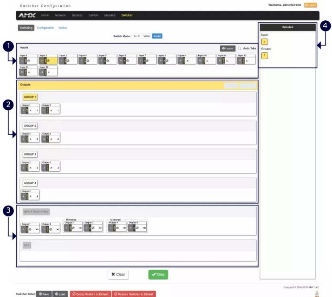
1- Inputs: This area enables you to select an Audio input to be switched to the selected Audio output.
NOTE: The Audio Switch Mode includes 4 HDMI audio inputs, 4 DXLINK audio inputs, 2 analog audio inputs and 4 Dante audio inputs.
2- Groups: Select the corresponding option button to select one audio output group. The Audio outputs in one group will output one selected audio source.
NOTE: The switcher includes 4 HDMI audio outputs, 2 DXLINK Outputs (mirrored with HDMI audio output 3 and 4 separately), 2 Analog Audio outputs, 2 AMP Audio outputs, and 4 Dante audio outputs, all these audio outputs can be grouped in Audio Configurations page or through API Commands.
3- INPUT PASS-THRU: This area enables you to select an audio output.
NOTE: The Audio switch mode includes 4 HDMI audio outputs and 2 DXLINK audio outputs for selecting. The 2 DXLINK audio outputs are mirrored with HDMI audio output 3 and 4 separately.
4- Selected: Shows the current selection.
Configuration
This tab enables you to set Video/Audio Input, Analog/Dante Microphone and Video/Audio Output.
In A/V Switch mode and Video Switch Mode, the corresponding setting parameters of Video In, Audio In, Analog/Dante Microphone, Video Out and Audio Out are the same. Take the settings of the parameters in A/V Switch Mode as examples.
Input Settings
This tab allows you to set Video/Audio Input, Analog/Dante Microphone.
1- Switching Settings: Select the corresponding option button to switch one A/V input to the selected output. For other settings, see "Switching Options" section.
2- Input: Shows the current selected Input port to be set.
3- Input Name: Change a name for the selected input port.
4- Config Viewer: Change the viewer of the settings pages.
Recently: Shows the current settings page.
Inputs Only: Shows Input settings page only.
Outputs Only: Shows Output settings page only.
5- Video Details: Click the button to open the Video Detail information page for the selected video input such as the value of Pixel Clock.
6- Restore to Default: Click to restore the values in current page of the selected video input to default settings.
7- Resolution: Shows the current resolution of the selected input port.
8- Enable HDR: Click to toggle whether HDR is enable or disable for the selected input port.
9- EDID Mode: Use the menus to indicate the desired EDID information to be sent to the selected video source. You can choose from one of the built-in EDID files which includes All Resolutions, only Full Screen Resolutions, or only Wide Screen Resolutions, or you can choose to mirror the EDID received from any connected display. Choosing one of the mirror modes turns off the HDMI Audio control for the selected input.
The Preferred EDID menu is only available if you select one of the internal EDID files (All, Full, or Wide). In this
mode you can select the specific preferred resolution to present to the connected source.
10- Save/Load EDID: Use the "Save EDID" menu to save the EDID settings as a bin file to the local PC. Use the "Load EDID" menu to load the EDID bin file from the local PC.
11- HDCP Setting: Click the check box to activate HDCP compliance on the selected input. HDCP compliance is active by default.
NOTE: In the following settings sections, the same parameters will not be introduced. See "Settings for Video In" section for details.
1- Audio Details: Click the button to enter the Audio detail information page of the selected input port.
2- Restore to Default: Click the button to restore the values of the selected audio input in current page to factory defaults.
3- Compression: Use the menu to select the compression level of the selected audio input. You can choose from Off, Low, Medium, High, and Custom. The default value is Off. Selecting any option other than Off enables you to adjust settings for Attack, Release, Ratio, and Threshold.
Attack: Sets the duration, in milliseconds, of the attack phase while compressing. You can set a value between 1 and 2000.
Release: Sets the duration, in milliseconds, of the release phase while compressing. You can set a value between 1 and 5000.
Ratio: Sets the ratio while compressing. You can set a value between 1 and 20.
Threshold: Sets the threshold while compressing. You can set a value between 0 and -60.
4- General: This area enables you to set analog format and gain for the selected input port.
Encoding: Shows the audio encoding format.
EDID Mode: Use the menus to set the desired EDID information to be sent to the selected audio source.
Input Mode: Use the menu to select the format for the audio input. You can choose from Stereo or Mono.
Input Gain (dB): Use the slider to adjust the gain level of the audio input. You can set the gain from -24 to +24dB in 1dB increments. The default setting is 0.
Level Meter: Set Level meter to enable or display (only if the input is routed to any of the audio output groups, the level meter can be set to enable). When it set to enable, the level meter value will be shown in the table.
Analog/Dante Microphone
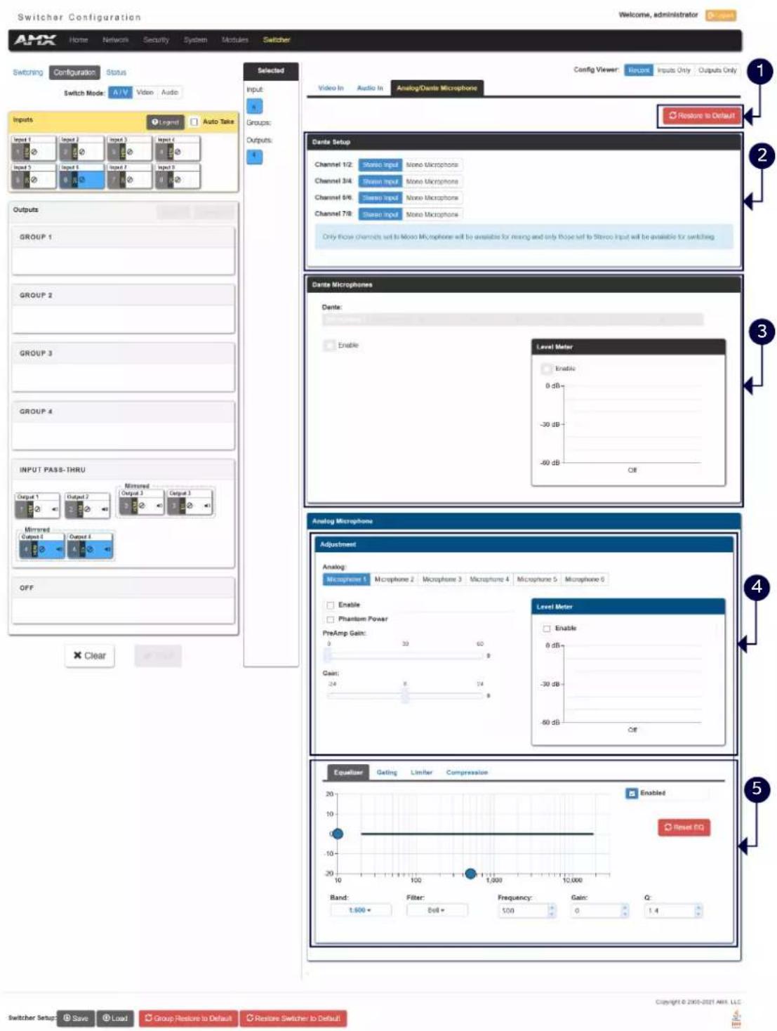
1- Restore to Default: Click to restore all mics configuration values to factory defaults.
2- Dante Setup: Select stereo audio or Mono mic for Dante audio inputs.
NOTE: Only those channels set to Mono Microphone will be available for mixing and only those set to stereo input will be available for switching.
3- Dante Microphone: Set Dante Microphones 1-8 to enable or disable. Click the check box to activate microphone for each Dante channel.
Level Meter: Set Dante audio level meter to enable or disable. When it set to enable, the level meter of the current selected Mic will be shown in the table.
4- Analog Microphone Adjustment 1: The tab enables you to set Microphone audio input settings.
Enable: Set analog Microphones 1-8 to enable or disable.
Phantom Power: Click the check boxes to activate phantom power for each individual mic. The unit supports a supply of up to 48V of phantom power for each mic input.
NOTE: Enabling Phantom Power could damage some devices connected to the microphone input if the devices are not designed to accept it.
You can set the following options for each microphone:
PreAmp Gain: Use the slider to set the preamp gain level for the mic. You can set the PreAmp Gain between 0 and 65 dB in 1 dB steps. Set the PreAmp Gain to 0 for line-level inputs.
Gain: Use the slider to set the input gain level for the mic. You can set the gain between -24 and +24 dB in 1 dB steps.
Level Meter: Set analog audio level meter to enable or disable. When it set to enable, the level meter of the current selected Mic will be shown in the table.
5- Analog Microphone Adjustment 2: This area contains a set of four tabs with different sets of options for more advanced microphone adjustments.
Equalizer: The equalizer is a 3-band parametric equalizer enabling you to set 3 frequencies to any value from 20Hz to 20KHz. The default center frequencies are 500Hz, 1000Hz, and 3000Hz. Each band is set individually by selecting the band from the Band menu then adjusting the remaining settings. A dynamics chart displays any activity on the equalizer band. Changing the Gain, Frequency, or Q settings can change the chart display.
Use the following options to change the settings on the equalizer:
Band: Use the menu to select which of the 3 equalizer bands you want to configure.
Filter Type: Use the menu to set the filter type for the selected equalizer band. You can choose from Bell, Band Pass, Band Stop, High Pass, Low Pass, Treble Shelf, and Bass Shelf.
Frequency: Use the up and down arrows or direct text entry to set the center frequency for the selected equalizer band. You
can set the center frequency to any value between 20Hz and 20KHz.
Gain: Use the up and down arrow buttons or direct text entry to adjust the gain/attention level of the audio input. You can set the gain from -12 to +12dB in 1dB increments. The default setting is 0.
Q: Q factor adjusts the vector graph from wider to narrower smoothing between inflection points on the equalizer band. The default setting is 1.4. The range is from 0.1 to 20.0 in 0.1 increment/decrement steps.
Gating: Use the menu to select the gating level of the selected microphone input. You can choose from Off, Low, Medium, High, and Custom. The default value is Off. Selecting any option other than Off enables you to adjust settings for Attack, Release, Depth, Hold Off, and Threshold.
Limiter: Use the menu to select the Limiter settings of the selected microphone input. You can choose from Off, Low, Medium, High, and Custom. The default value is Off. Selecting any option other than Off enables you to adjust settings for Attack, Release and Threshold.
Compression: Use the menu to select the compression level of the selected Microphone input. You can choose from Off, Low, Medium, High, and Custom. The default value is Off. Selecting any option other than Off enables you to adjust settings for Attack, Release, Ratio, and Threshold.
The following settings serve identical purposes with identical ranges for each tab on which they appear:
Attack: Sets the duration, in milliseconds, of the attack phase. You can set a value between 1 and 2000.
Release: Sets the duration, in milliseconds, of the release phase. You can set a value between 1 and 5000.
Depth: Sets the depth in decibels. You can set a value between 0 and 20.
Ratio: Sets the ratio. You can set a value between 1 and 20.
Hold Off: Sets the gating hold off time. You can set a value between 0.25 and 4 seconds in 0.25 increments.
Enabled: Click to enable or disable the equalizer settings.
Reset EQ: Click to restore Equalizer settings to factory defaults.
Output Settings
This tab enables you to set Video/Audio Output.
Video Output Settings
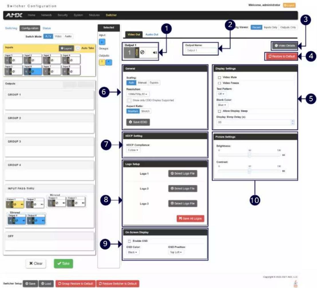
1- Output: Shows the current selected Output port to set.
2- Output Name: Change a name for the selected Output.
3- Video Details: Click the button to open the Video Detail information page for the selected video output.
4- Restore to Default: Click the button to restore the current values of the selected video output in current to factory defaults.
5- Display Settings: Video Mute: Click to toggle whether the output video is muted (blanked) on the video output.
Video Freeze: Click the check box to freeze the current image so that it remains on the screen.
Test Pattern: Use the menu to choose an output test pattern to display on the video output. Select Off to disable the logo or test pattern and view video from the selected source. You can choose from Off, Black, Blue, White, Red,
Green. If you have uploaded a logo to display on the output, you can also select the logo from this menu.
Blank Color: Use the drop-down menu to select the color of the blank screen on the output. If you have uploaded a logo to display on the output, you can also select the logo from this menu.
Allow Display Sleep: Click to toggle whether the display sleep is enabled on the video output.
Display Sleep Delay (s): If the display sleep is enabled (the box in front of Allow Display Sleep is checked), you can set display sleep delay time through up down buttons.
6- General (Scaling/Resolution/Aspect Ratio): Click Auto to have the unit automatically set the video resolution for the selected output display based on the EDID information received from the connected display device. Click Manual to manually override the video resolution for the output display. After choosing Manual, select a resolution and an aspect ratio from the corresponding menus. Select Bypass to disable scaling and send unscaled video from the selected input to the display.
Save EDID: Click the button to save the current EDID settings to local PC.
7- HDCP Settings (Follow/HDCP 2.2/HDCP 1.4/NO HDCP): Click to set HDCP for current selected Output. "Follow" means that the HDCP of the current selected Output is following the connected display.
8- Logo Setup: The Logo Setup area enables you to load up to three PNG image files for the display on each video output port separately. Click each Select Logo File button to locate and upload an image file to the unit's local memory, then click the Save All Logos button to load the image files into memory. There is 200KB of memory available for storing the three image files on each video output.
NOTE: Large images can cause a slowdown in performance. AMX recommends using an image no greater than 1280x720.
9- On-Screen Display: This area allows you to activate the on-screen display. When enabled, the input name and resolution displays in a small box in a corner of the screen whenever you select a new input source. From the available menus in the same area, you can select the color scheme and location of the OSD.
10- Picture Settings: Use the sliders to set the brightness and contrast for the selected video output.
Audio Out Settings in A/V Switch Mode
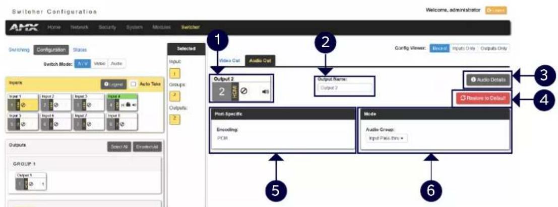
1- Output: Shows the current selected Input port to set.
2- Output Name: Change a name for the selected Output.
3- Audio Details: Click the button to open the Audio Detail information page for the selected audio.
4- Restore to Default: Click the button to restore the values of the selected audio output in current page to default settings.
5- Port-Specific (Encoding): Shows Audio Encoding format information.
6- Mode (Audio Group): Click from the drop-down menu to set the selected audio output to one group or for input pass-through. When set it to off, the selected port will not output audio.
Audio Output Settings in Audio Switch Mode
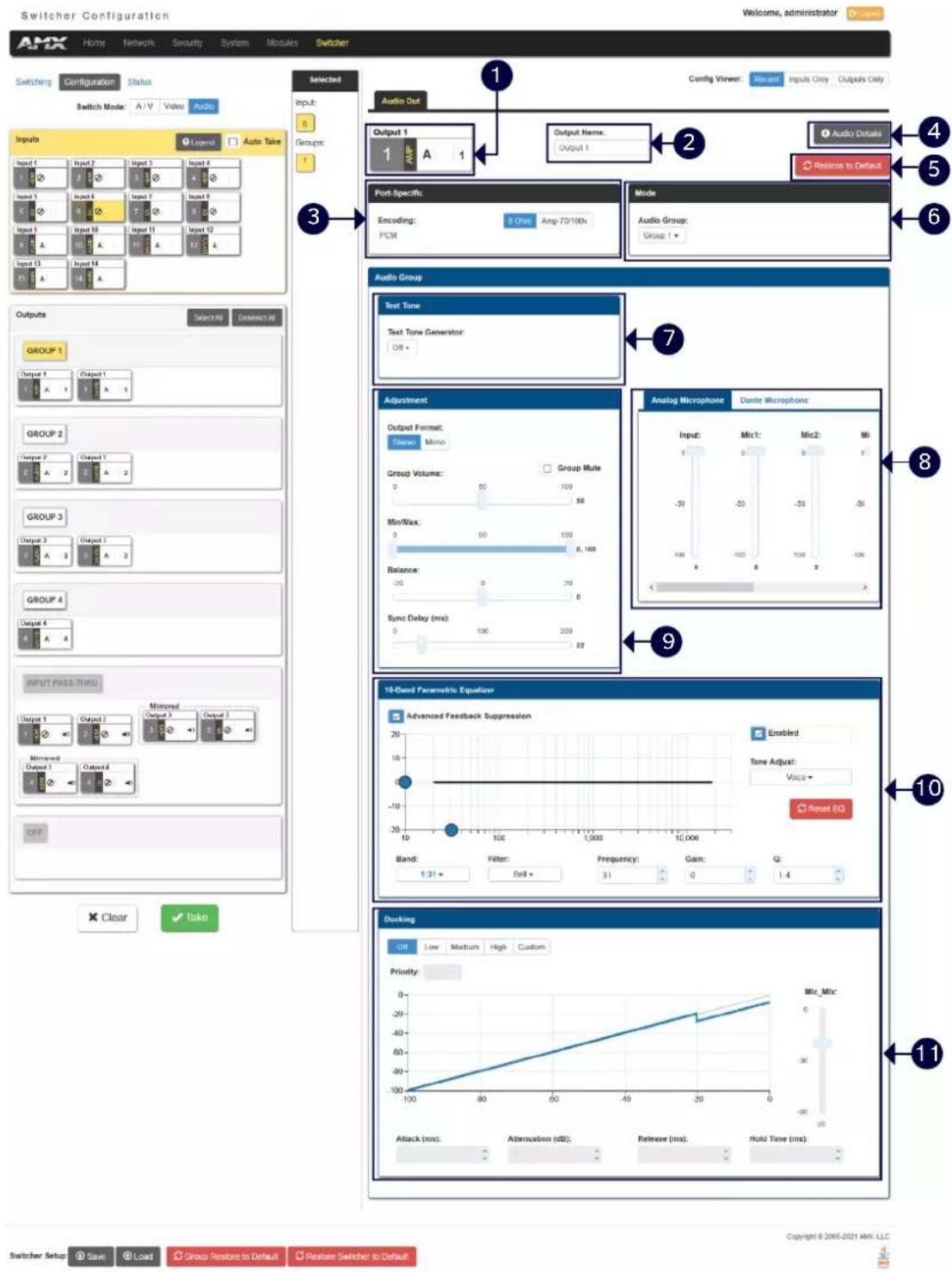
1- Audio Output: Shows the selected audio output port.
2- Output Name: Change a name for the selected Audio output.
3- Port-Specific: Shows the Audio Encoding format. When the AMP port is selected, use 8ohm and 70/100v buttons to set the amplifier mode.
4- Audio Details: Click the button to open the Audio Detail information page for the selected audio.
5- Restore to Default: Click the button to restore the values of the selected audio output in current page to default settings.
6- Mode: Set the selected audio output to one group.
NOTE: Numbers of the parameters from 1 to 4 are the settings for a selected audio output. The following numbers
of parameters from 5-10 are the settings for the selected group.
7- Test Tone Generator: The tone generator provides an internally generated audible tone. The selected tone overrides any input source selection. Selecting 'Off' removes the override, allowing you to hear audio from the selected source. You can choose from Off, 60Hz, 250Hz, 400Hz, 1kHz, 3kHz, 5kHz, 10kHz, Pink Noise, and White Noise.
8- Analog/Dante Microphone: Use the sliders to set the mix levels for the audio inputs. Each device has its own mix level slider. You can set each level from 0 to 100dB.
9- Adjustment:
Output Format: Use the menu to change the audio format of the selected audio outputs in this group. You can set the audio format to Stereo or Mono. The default setting is stereo.
Use the sliders to set the output levels for the selected audio output group. You can set the following options for the selected audio output group:
Group Volume: Use the slider to set the volume of the selected audio outputs of the group. You can set the volume from 0 to 100. The default setting is 20. Group Mute: Click the check box to mute the audio outputs of the group.
Min/Max: Use the sliders to adjust the minimum and maximum volume of the audio output group. There are separate sliders on this option for minimum and maximum volume. You can set the maximum volume from 0 to 100 in increments of 1. The default value is 100. You can set the minimum volume from 0 to 100 in increments of 1. The default value is 0.
Balance: Use the slider to adjust the balance level of the selected audio output group. You can set the balance level from -20 to +20. The default value is 0.
Sync Delay: Use the slider to set the number of milliseconds to delay the audio. The default value is 32.
Additionally, you can silence the audio output group by clicking the Group Mute check box.
10- 10 Band Parametric Equalizer: The equalizer is a 10-band parametric equalizer enabling you to set any of the 10 default frequencies (32Hz, 62Hz, 125Hz, 250Hz, 500Hz, 1000Hz, 2000Hz, 4000Hz, 8000Hz, 16000Hz) to any value from 20Hz to 20KHz. Each band is set individually by selecting the band from the Band menu then adjusting the remaining settings. A dynamic graph displays the resulting frequency response of the equalizer band. Changing the Gain, Frequency, or Q settings can change the frequency response.
Use the following options to change the settings on the equalizer:
Band: Use the menu to select which of the 10 equalizer bands you want to configure.
Filter Type: Use the menu to set the filter type for the selected equalizer band. You can choose from Bell, Band Pass, Band Stop, High Pass, Low Pass, Treble Shelf, and Bass Shelf.
Frequency: Use the up and down arrows or direct text entry to set the center frequency for the selected equalizer band. You can set the center frequency to any value between 20Hz and 20KHz.
Gain: Use the up and down arrow buttons or direct text entry to adjust the gain/attention level of the selected band. You can set the gain from -12 to +12dB in 1dB increments. The default setting is 0.
Q: Q factor adjusts the filter from wider to narrower smoothing between inflection points on the frequency response. The default setting is 1.4. The range is from 0.1 to 20.0 in 0.1 increment/decrement steps.
Tone Adjust: Use the menu to select a fixed adjustment to the frequency response depending on the current use. You can choose from Off, Movie, Voice, and Music.
Enabled: Click to enable or disable the equalizer settings.
11- Ducking: Use the menu to set the ducking level of the audio output. You can choose from Off, Low, Medium, High, and Custom. Selecting Custom activates settings you can adjust for Threshold, Attack, Release, Attenuation, and Hold-time. The default setting is Off.
Priority: Use this menu to set the ducking priority for the microphones. You can choose from Off or Mic1.
Threshold: Use the sliders to adjust the threshold levels for each microphone. You can set the threshold to any value between 0 and -60.
NOTE: The settings of numbers 5-10 are all valid for the audio outputs in the selected group.
Status
The tab enables you to check the fan, power and temperature status and set the alarm on/off. And you can also set LCD display parameters and mute all video and audio groups.
![Switcher Configuration Welcome, administrator AMX Home Network Security System Modules Switcher Switching Configuration Status 1 System Auto-Setup 2 Fan Alarm: 3 Power Alarm: 4 Temperature Alarm: 5 Refresh System Information Fan Speeds (RPM): [728.740] Temperatures (°C): [52.60(4.3)] Front Panel Enable Lockout Full Menu Only Video Mute All Mute Audio Groups LCD Intensity: 5 55 100 50 Switcher Setup Save Load Group Restore to Default Restore Switcher to Default Copyright © 2006-2021 AMX, LLC](/content/2026/05/894730/images/ab855a2f19e4479f0f9fca68d99c5aa719dcad82612a7b3797f87f821d18ed63.jpg)
1- System Auto-Setup: Click the check box to set the system auto-setup to enable or disable.
2- Fan Alarm: Click the green circle to set Fan Alarm to ON/OFF. The default setting is OFF.
3- Power Alarm: Click the green circle to set Power Alarm to ON/OFF. The default setting is OFF.
4- Temperature Alarm: Click the green circle to set Temperature Alarm to ON/OFF. The default setting is OFF.
5- Refresh: Click the button to refresh the status.
6- System Information: This area provides the following read-only information about your unit:
Fan Speed (RPM)
Temperature (°C)
7- Front Panel: This area provides the following setting options for LCD displays on front panel:
Enable Lockout and Full/Menu Only: Click the check box to activate a lockout of some or all of the buttons on the front panel. The type of lockout in the Lockout Mode section. Select Full Lockout if you want the lockout to block the use of all front panel buttons. Select Menu-only Lockout if you want the lockout to only block the use of the menu options on the front panel. The Switch, Take, Status, Volume, and Mute buttons are still available with this option.
Video Mute All: You can mute all Video outputs by clicking the check box.
Mute Audio Groups: You can silence all Audio Groups by clicking the check box.
LCD Intensity: Use the sliders to adjust the backlight intensity of the LCD display and the LEDs on front panel buttons. You can set the backlight intensity for each option between 0 and 100. The default setting for each option is 50.
Firmware Upgrade
Upgrading firmware on an Enova DVX All-In-One Presentation Switcher involves downloading the latest firmware files from www.amx.com and using NetLinx Studio to transfer the files to a target DVX. The NetLinx Studio software application (available for free download from www.amx.com) provides the ability to transfer KIT firmware files to a NetLinx device such as the DVX.
Use the Online Device tree in NetLinx Studio to view the firmware files currently loaded on the Central Controller. The following picture shows an example Online Tree:
![NX Master (Port 0) Device Controller (Port 5001) Switcher (Port 5002) System 1 Devices [192.168.20.242] 00000 - DVX-3266 Master (1.8.29) 05001 - DVX-CRIC Controller (v8.4.4) 05002 - DVX-3266 (V1.4.6)](/content/2026/05/894730/images/2f728f9472d1c9e21ac539ae76a0313541cc8120fd12343db11bda5f9615a121.jpg)
Before You Start
Perform the following steps before upgrading your firmware version:
- Verify you have the latest version of NetLinx Studio on your PC. Go to www.amx.com to download the latest version.
- Go to www.gmx.com and download the latest Firmware file. Firmware files are available to download from www.gmx.com – on the product's page in the online catalog.
- Verify that an Ethernet cable is connected from the DVX to the PC.
- Verify that the DVX is powered On.
- Launch NetLinx Studio and open the Online Device Tree.
Required Order of Firmware Updates for DVX Controllers
Upgrade firmware in the following order:
- First, upgrade the A/V Switcher/Scaler firmware.
- When that process is complete, upgrade the Controller firmware.
- When that process is complete, upgrade the Device firmware.
NOTE: ALWAYS consult the Readme.TXT file bundled with the firmware file for any special instructions before upgrading to a newer firmware version. If no specifics are provided, use the order provided above.
Sending Firmware (\*.KIT) Files to the DVX
Use the Firmware Transfers options in the Tools menu to update the firmware in the DVX. NetLinx Devices such as the DVX use KIT files for firmware upgrades.
Programming
Overview
The chapter defines all programming commands available for the DVX-3266-4K and DVX-2265-4K.
NOTE: This chapter lists programming commands unique to the DVX. Please consult the WebConsole & Programming Guide for NX-Series Controllers for more details on NetLinx Controller commands. The DVX supports all commands compatible with the NX-3200.
NetLinx Channels
The following sections define the NetLinx channels available for the DVX-3266-4K and DVX-2265-4K.
| Channel Ports Description | ||
| 24 | 1-4 | Volume Up |
| 25 1-4 Volume Down | ||
| 26 | 1-4 | Volume Mute Cycle |
| 31 | 1-4 | Switches video input 1 to the video output specified in the DPS |
| 32 | 1-4 | Switches video input 2 to the video output specified in the DPS |
| 33 | 1-4 | Switches video input 3 to the video output specified in the DPS |
| 34 | 1-4 | Switches video input 4 to the video output specified in the DPS |
| 35 | 1-4 | Switches video input 5 to the video output specified in the DPS |
| 36 | 1-4 | Switches video input 6 to the video output specified in the DPS |
| 37 | 1-4 | Switches video input 7 to the video output specified in the DPS |
| 38 | 1-4 | Switches video input 8 to the video output specified in the DPS |
| 41 | 1-4 | Switches audio input 1 to the audio group specified in the DPS |
| 42 | 1-4 | Switches audio input 2 to the audio group specified in the DPS |
| 43 | 1-4 | Switches audio input 3 to the audio group specified in the DPS |
| 44 | 1-4 | Switches audio input 4 to the audio group specified in the DPS |
| 45 | 1-4 | Switches audio input 5 to the audio group specified in the DPS |
| 46 | 1-4 | Switches audio input 6 to the audio group specified in the DPS |
| 47 | 1-4 | Switches audio input 7 to the audio group specified in the DPS |
| 48 | 1-4 | Switches audio input 8 to the audio group specified in the DPS |
| 49 | 1-4 | Switches audio input 9 to the audio group specified in the DPS |
| 50 | 1-4 | Switches audio input 10 to the audio group specified in the DPS |
| 51 | 1-4 | Switches audio input 11 to the audio group specified in the DPS |
| 52 | 1-4 | Switches audio input 12 to the audio group specified in the DPS |
| 53 | 1-4 | Switches audio input 13 to the audio group specified in the DPS |
| 54 | 1-4 | Switches audio input 14 to the audio group specified in the DPS |
| 70 1-4 Video Output Enable | ||
| 71 | 1-14 | Mic Enable (Mono) |
| 140 1-4 Gain Up | ||
| 141 1-4 Gain Down | ||
| 142 | 1-10 | Black and White State |
| 143 1-4 Gain Mute | ||
| 164 | 1-4 | Balance Ramp Up |
| 165 | 1-4 | Balance Ramp Down |
| 199 | 1-4 | Volume Mute Set and State |
| 210 | 1-4 | Video Mute State |
| 211 | 2-4 | DXLink Video Mute State |
| 213 | 1-4 | Video Freeze State |
| 214 | 2-4 | DXLink Video Freeze State |
| 216 | 1 | Fan Alarm |
| 217 | 1 | Temperature Alarm |
| 234 1-4 OSD State | ||
| 235 2-4 DXLink OSD State | ||
NetLinx Levels
The following sections define the NetLinx levels available for the DVX-3266-4K and DVX-2265-4K.
| Level | Ports | Range | Function |
| 1 | 1-4 | 0-100 | Output volume |
| 2 | 1-4 | (-20) - (20) | Audio Output Balance |
| 5 | 1-14 | (-24) - (24) | Audio Input Gain |
| 8 | 1 | Temperature (read-only level) | |
| 20 | 1-4 | 0-100 | Video Output Brightness |
| 21 | 2-4 | 0-100 | DXLink Video Output Brightness |
| 22 | 1-4 | 0-100 | Video Output Contrast |
| 23 | 2-4 | 0-100 | DXLink Video Output Contrast |
| 31 | 1-4 | (-12) -(12) | Audio EQ Band 1 |
| 32 | 1-4 | (-12) -(12) | Audio EQ Band 2 |
| 33 | 1-4 | (-12) -(12) | Audio EQ Band 3 |
| 34 | 1-4 | (-12) -(12) | Audio EQ Band 4 |
| 35 | 1-4 | (-12) -(12) | Audio EQ Band 5 |
| 36 | 1-4 | (-12) -(12) | Audio EQ Band 6 |
| 37 | 1-4 | (-12) -(12) | Audio EQ Band 7 |
| 38 | 1-4 | (-12) -(12) | Audio EQ Band 8 |
| 39 | 1-4 | (-12) -(12) | Audio EQ Band 9 |
| 40 | 1-4 | (-12) -(12) | Audio EQ Band 10 |
| 41 | 1-4 | (-100)-0 | Audio Program Source Mixing Level |
| 42 | 1-4 | (-100)-0 | Audio Line Mic 1 Mixing Level |
| 43 | 1-4 | (-100)-0 | Audio Line Mic 2 Mixing Level |
| 44 | 1-4 | (-100)-0 | Audio Line Mic 3 Mixing Level |
| 45 | 1-4 | (-100)-0 | Audio Line Mic 4 Mixing Level |
| 46 | 1-4 | (-100)-0 | Audio Line Mic 5 Mixing Level |
| 47 | 1-4 | (-100)-0 | Audio Line Mic 6 Mixing Level |
| 50 | 1-4 1-8 | Video Switching: Level 50 for each output port 1-4 will be a value from 1 to 8 indicating which video input is switched to that output. Changing the value of this level will result in a video switch. | |
| 51 | 1-4 | 1-14 | Audio Switching: Level 51 for each audio group port 1-4 willbe a value from 1 to 14 indicating which audio input is switched to that audio group. Changing the value of this level will result in an audio switch. |
| 52 | 1-6 | 0-60 | Audio Mic Preamp Gain |
| 53 | 1-6 | (-24) -(24) | Audio Mic Gain |
| 61 | 1-6 | (-12) -(12) | Mic EQ Band 1 |
| 62 | 1-6 | (-12) -(12) | Mic EQ Band 2 |
| 63 | 1-6 | (-12) -(12) | Mic EQ Band 3 |
| 71 | 1-4 | (-100)-0 | Dante Mic 1 Mixing Level |
| 72 | 1-4 | (-100)-0 | Dante Mic 2 Mixing Level |
| 73 | 1-4 | (-100)-0 | Dante Mic 3 Mixing Level |
| 74 | 1-4 | (-100)-0 | Dante Mic 4 Mixing Level |
| 75 | 1-4 | (-100)-0 | Dante Mic 5 Mixing Level |
| 76 | 1-4 | (-100)-0 | Dante Mic 6 Mixing Level |
| 77 | 1-4 | (-100)-0 | Dante Mic 7 Mixing Level |
| 78 | 1-4 | (-100)-0 | Dante Mic 8 Mixing Level |
Port Functionality Mapping
The following table lists the port functionality mapping for the audio/video ports on the DVX-3266-4K and DVX-2265-4K.
| Port Functionality Mapping (A/V Switcher 5002) | ||
| Port number | Description | Address |
| 1 | Audio/Video Input 1 | 05002:1:0 |
| 2 | Audio/Video Input 2 | 05002:2:0 |
| 3 | Audio/Video Input 3 | 05002:3:0 |
| 4 | Audio/Video Input 4 | 05002:4:0 |
| 5 | Audio/Video Input 5 | 05002:5:0 |
| 6 | Audio/Video Input 6 | 05002:6:0 |
| 7 | Audio/Video Input 7 | 05002:7:0 |
| 8 | Audio/Video Input 8 | 05002:8:0 |
| 9 | Audio Input 9 (Analog) | 05002:9:0 |
| 10 | Audio Input 10 (Analog) | 05002:10:0 |
| 11 | Audio Input 11 (Dante) | 05002:11:0 |
| 12 | Audio Input 12 (Dante) | 05002:12:0 |
| 13 | Audio Input 13 (Dante) | 05002:13:0 |
| 14 | Audio Input 14 (Dante) | 05002:14:0 |
| 1 | Analog MIC In 1 | 05002:1:0 |
| 2 | Analog MIC In 2 | 05002:2:0 |
| 3 | Analog MIC In 3 | 05002:3:0 |
| 4 | Analog MIC In 4 | 05002:4:0 |
| 5 | Analog MIC In 5 | 05002:5:0 |
| 6 | Analog MIC In 6 | 05002:6:0 |
| 7 Dante MIC In 1 | 05002:7:0 | |
| 8 Dante MIC In 2 05002:8:0 | ||
| 9 Dante MIC In 3 05002:9:0 | ||
| 10 | Dante MIC In 4 | 05002:10:0 |
| 11 | Dante MIC In 5 | 05002:11:0 |
| 12 | Dante MIC In 6 | 05002:12:0 |
| 13 | Dante MIC In 7 | 05002:13:0 |
| 14 | Dante MIC In 8 | 05002:14:0 |
| 1 | Audio/Video Output 1 | 05002:1:0 |
| 2 | Audio/Video Output 2 | 05002:2:0 |
| 3 | Audio/Video Output 3 | 05002:3:0 |
| 4 | Audio/Video Output 4 | 05002:4:0 |
| 1 Audio Group 1 05002:1:0 | ||
| 2 Audio Group 2 05002:2:0 | ||
| 3 Audio Group 3 05002:3:0 | ||
| 4 Audio Group 4 05002:4:0 | ||
| 1 | Analog Audio Output 1 (Amplified) | 05002:1:0 |
| 2 Analog Audio Output 2 05002:2:0 | ||
| 3 | Analog Audio Output 3 | 05002:3:0 |
| 1 | Dante Audio Output 1 | 05002:1:0 |
| 2 | Dante Audio Output 2 | 05002:2:0 |
| 3 | Dante Audio Output 3 | 05002:3:0 |
| 4 | Dante Audio Output 4 | 05002:4:0 |
Port Numbers
The following table lists the port numbers for the DVX-2265-4K and DVX-3266-4K models:
| Port Functionality Mapping (Control Device 5001) | |||
| RS-232 | IR/Serial | I/O | Relay |
| Ports 1, 2 | Ports 11, 12 | Port 22 | Port 21 |
SEND_COMMANDs
| NO | Command | Syntax | Example |
| Video SEND_COMMANDs | |||
| 1 | CI0 | Command:SEND_COMMAND,"CI0" | Command:SEND_COMMAND SWITCHER, "CI101,2" |
| Return:SWITCH-LVIDEOI0SWITCH-LAUDIOI0Description:Switches both the audio and video input to the output port.input = The audio/video input port number.output = The video output port number and the audio group number to switch to. | Return:SWITCH-LVIDEOI101SWITCH-LAUDIOI101SWITCH-LVIDEOI102SWITCH-LAUDIOI102Description:Switch video input port #1 to output port #1 and #2, Switch audio input port #1 to audio group #1 and #2. | ||
| 2 | CLI0 | Command:SEND_COMMAND,"CLI0" | Command:SEND_COMMAND SWITCHER, "CLALLI201,2" |
| Return:SWITCH-LI0Description:Switches the audio or video (or both) inputs to the output port. Set to 0 for disconnect.sl = AUDIO or VIDEO or ALL. ALL = both AUDIO and VIDEO.input = The audio/video input port number.output = The video output port number and the audio group number to switch to.Command:SEND_COMMAND,"VI0" | Return:SWITCH-LVIDEOI201SWITCH-LAUDIOI201SWITCH-LVIDEOI202SWITCH-LAUDIOI202Description:Switch video input port #2 to output port #1 and #2. Switch audio input port #2 to audio group #1 and #2.Command:SEND_COMMAND SWITCHER,"VI101,2" | ||
| 3 VI | 0 | ||
| Return:SWITCH-LVIDEOI0Description:Switches input to one or more outputs for switcher level Video. Setto 0 for disconnect.input = The source input port number.output = The output port number to switch to. | Return:SWITCH-LVIDEOI101SWITCH-LVIDEOI102Description:Switch video input port #1 to output port #1 and #2. | ||
| 4 ?INPUT | Command:SEND_COMMAND,"?INPUT-,""Return:SWITCH-LI0.Description:Requests which audio or video input ports are connected to the output port. If the output port is not connected to any input port then the reply will indicate this with an input port number of ZERO (0).Variables:sl = AUDIO or VIDEO.output = The output port number. | Command:SEND_COMMAND SWITCHER,"?INPUT-AUDIO,1 "Return:SWITCH-LAUDIOI101Description:Requests which audio input ports are connected to the output (audio group) port #1. | |
| 5 ?OUTPUT | Command:SEND_COMMAND,"?OUTPUT-,""Return:SWITCH-L0.Description:Requests which audio or video output ports are connected to the input port. If the output port is not connected to any input port then the reply will indicate this with an input port number of ZERO (0).Variables:sl = AUDIO, VIDEO, or ALL. ALL = both AUDIO -and- VIDEO.input = The source input port number. | Command:SEND_COMMAND SWITCHER,"?OUTPUT-VIDEO,1 ""Return:SWITCH-LVIDEOI101,2,3,4Description:Requests which video output ports are connected to the input port #1 | |
| 6 ?VIDIN_STATUS | Command:SEND_COMMAND,""?VIDIN_STATUS"Return:VIDIN_STATUS-Description:Requests the status of the video input port addressed by D:P:S.{NO SIGNAL;VALID SIGNAL;} | Command:SEND_COMMANDVIDEO_INPUT_1,"?VIDIN_STATUS"Return:VIDIN_STATUS-NO SIGNAL | |
| 7 VIDIN_PREF_EDID | Command:SEND_COMMAND,""VIDIN_PREF_EDID-""Return:VIDIN_PREF_EDID-Description:To Set the input preferred EDID for the | Command:SEND_COMMANDVIDEO_INPUT_1,""VIDIN_PREF_EDID-1920x1200,60"Return:VIDIN_PREF_EDID-1920x1200,60 | |
| video input port addressed by D:P:SNote: You can only set the preferred resolution if you use the VIDIN_EDID command to set the EDID source to All HD Resolutions, HD Wide-screen, HD Full-screen, 4K or 4K60. | Description:Set input preferred EDID to (1920x1200@60Hz) for input port #1. | ||
| Variables:{Different resolution lists for different EDID modes. For a list of supported resolutions, see the Input Resolutions Supported in Specifications} | |||
| 8 ?VIDIN_PREF_EDID | Command:SEND_COMMAND,""?VIDIN_PREF_EDID"Return:VIDIN_PREF_EDID--Description:To Get the preferred EDID of the video input port addressed by D:P:S. | Command:SEND_COMMANDVIDEO_INPUT_1,""?VIDIN_PREF_EDID"Return:VIDIN_PREF_EDID-1920x1200,60Description:The preferred EDID of Input #1 is 1920x1200@60Hz | |
| 9 VIDIN_EDID | Command:SEND_COMMAND,"'VIDIN_EDID-<4K|4K60|All Resolutions|Wide-Screen|Full-Screen|Custom>"Return:VIDIN_EDID-<4K|4K60|All Resolutions|Wide-Screen|Full-Screen|Custom>DescriptionTo Set Input EDID Mode for the video input port addressed by D:P:S. | Command:SEND_COMMANDVIDEO_INPUT_1,"'VIDIN_EDID-4K60"Return:VIDIN_EDID-4K60Description:Set input port #1 EDID mode as 4K60 | |
| 10 | ?VIDIN_EDID | Command:SEND_COMMAND,"?VIDIN_EDID"Return:VIDIN_EDID-Description:To Get Input EDID Mode for the video input port addressed by D:P:S.mode =4K|4K60|AllResolutions|Wide-Screen|Full-Screen|Custom | Command:SEND_COMMANDVIDEO_INPUT_1,"?VIDIN_EDID"Return:VIDIN_EDID-4K60Description:The input port #1 EDID mode is 4K60 |
| 11 | VIDIN_HDCP | Command:SEND_COMMAND,"VIDIN_HDCP-"Return:VIDIN_HDCP-Description:To Set Input HDCP Compliant for the video input port addressed by D:P:S. | Command:SEND_COMMANDVIDEO_INPUT_1,"VIDIN_HDCP-ENABLE"Return:VIDIN_HDCP-ENABLE |
| 12 | ?VIDIN_HDCP | Command:SEND_COMMAND,"?VIDIN_HDCP"Return:VIDIN_HDCP-Description:To Get Input HDCP Compliant for the video input port addressed by D:P:S. | Command:SEND_COMMANDVIDEO_INPUT_1,"?VIDIN_HDCP"Return:VIDIN_HDCP-ENABLE |
| 13 | ?VIDIN_RES_REF | Command:SEND_COMMAND,"?VIDIN_RES_REF"Return:VIDIN_RES_REF-Description:Requests to resolution of the video input port addressed by the D:P:S. | Command:SEND_COMMANDVIDEO_INPUT_1,"?VIDIN_RES_REF"Return:VIDIN_RES_REF-1920x1080,60 |
| 14 | VIDIN_NAME | Command:SEND_COMMAND,“‘‘VIDIN_NAME-’”Return:VIDIN_NAME-Description:Setsthe name of the video input port addressed by the D:P:S to. Thelength is limited to 31 characters.Valid characters are:a-z // lower case lettersA-Z // upper case letters0-9 // numeric#.-_=+ // special characters hash,period, dash, underscore, equal, plus | Command:SEND_COMMANDVIDEO_INPUT_1,“‘‘VIDIN_NAME-DVD”Return:VIDIN_NAME-DVDDescription:Setsthe name to DVD of the video input port #1 |
| 15 | ?VIDIN_NAME | Command:SEND_COMMAND,“‘‘?VIDIN_NAME ’”Return:VIDIN_NAME-Description:Requests the name of the video input port addressed by the D:P:S. | Command:SEND_COMMANDVIDEO_INPUT_1,“‘‘?VIDIN_NAME ’”Return:VIDIN_NAME-DVDDescription:The name of the video input port #1 is DVD. |
| 16 | VIDIN_HDR | Command:SEND_COMMAND,“‘‘VIDIN_HDR-’”Return:VIDIN_HDCP-Description:To Set Input HDR Compliant for the video input port addressed by D:P:S. | Command:SEND_COMMANDVIDEO_INPUT_1,“‘‘VIDIN_HDR-NONE’”Return:VIDIN_HDR-NONE |
| 17 | ?VIDIN_HDR | Command:SEND_COMMAND,"?VIDIN_HDR"Return:VIDIN_HDR--Description:To Get Input HDR Compliant for the video input port addressed by D:P:S. | Command:SEND_COMMANDVIDEO_INPUT_1,"?VIDIN_HDR"Return:VIDIN_HDR-NONE |
| 18 | VIDIN_EDID_DATA | Command:SEND_COMMAND,"VIDIN_EDID_DATA-""Return:VIDIN_EDID--VIDIN_PREF_EDID--Description:Set the EDID data of the input port with D:P:S. If the EDID data is within the EDID range of the AMX product, the mode and resolution to which EDID belongs will be displayed, otherwise no response will be returned. | Command:SEND_COMMANDVIDEO_INPUT_1,"VIDIN_EDID_DATA-00FFFFFFF0005B8001802000000...0000000000000000000000000000000000000000000000000000000000000000000000000000000000000000000000000000"Return:VIDIN_EDID-4K60VIDIN_PREF_EDID-4096x2160p,50 |
| 19 | ?VIDIN_EDID_DATA | Command:SEND_COMMAND,"?VIDIN_EDID_DATA"Return:VIDIN_EDID_DATA--Description:Requests the EDID data of the video input port addressed by D:P:S. | Command:SEND_COMMANDVIDEO_INPUT_1,"?VIDIN_EDID_DATA"Return:VIDIN_EDID_DATA-00FFFFFFF0005B8001802000000...0000000000000000000000000000000000000000000000000000000000000000000AB |
| 20 | VIDOUT_SCALEVIDOUT_RES_AUTO | Command:SEND_COMMAND,"VIDOUT_SCALE--"Return:VIDOUT_SCALE--Description:Sets the Scaling Mode on the video output port. | Command:SEND_COMMANDVIDEO_OUTPUT_1,"VIDOUT_SCALE-AUTO"Return:VIDOUT_SCALE-AUTODescription:Sets output port #1 scaling mode to auto |
| 21 | ?VIDOUT_SCALE?VIDOUT_RES_AUTO. | Command:SEND_COMMAND,""?VIDOUT_SCALE"Return:VIDOUT_SCALE--Description:Requests the current Scaling Mode of the video output port. | Command:SEND_COMMANDVIDEO_OUTPUT_1,""?VIDOUT_SCALE"Return:VIDOUT_SCALE-AutoDescription:Scaling mode of output port #1 is auto |
| 22 | VIDOUT_RES_REF | Command:SEND_COMMAND,"'VIDOUT_RES_REF-x"Return:VIDOUT_RES_REF-xDescription:Set the resolution and refresh rate of the video through the output port and also sets the Scaling Mode to MANUAL. | Command:SEND_COMMANDVIDEO_OUTPUT_1,"'VIDOUT_RES_REF-3840x2160,60"Return:VIDOUT_RES_REF-3840x2160p,60Description:Set the resolution and refresh rate to 3840x2160@60 for the video output port #1. |
| Variables:horizontal = An integer value representing the horizontal.vertical = An integer value representing the vertical. May have an additional qualifier such as 'p'.refresh-rate = An integer value representing the refresh rate.{4096X2160p,604096X2160p,304096X2160p,254096X2160p,243840x2160p,603840x2160p,50 | |||
| 3840x2160p,303840x2160p,253840x2160p,241920x1080p,601920x1080p,501280x720p,601280x720p,501920x1200,601680x1050,601600x1200,601600x900,601440x900,601366x768,601360x768,601280x1024,601280x960,601280x800,601280x768,601024x768,60800x600,60} | |||
| 23 | ?VIDOUT_RES_REF?VIDOUT_RES | Command:SEND_COMMAND,,"?VIDOUT_RES_REF"Return:VIDOUT_RES_REF-x,,Description:Requests the resolution and refresh rate of the video through the output port. | Command:SEND_COMMANDVIDEO_OUTPUT_1,""?VIDOUT_RES_REF"Return:VIDOUT_RES_REF-3840x2160p,60Description:Resolution and refresh rate of video output port #1 is 3840x2160@60. |
| 24 | VIDOUT_TESTPATVIDEO_TESTPATTERN | Command:SEND_COMMAND,""VIDOUT_TESTPAT--"Return:VIDOUT_TESTPAT--Description:Setsthe test pattern for the video output port.Variables:={BLACK|BLUE|WHITE|RED|GREEN|OFF} | Command:SEND_COMMANDVIDEO_OUTPUT_1,""VIDOUT_TESTPAT-RED"Return:VIDOUT_TESTPAT-REDDescription:Setsthe test pattern to REDfor the video output port #1. |
| 25 | ?VIDOUT_TESTPAT?VIDEO_TESTPATTERN | Command:SEND_COMMAND,""?VIDOUT_TESTPAT"Return:VIDOUT_TESTPAT--Description:Requests the test pattern setting for the video output port. | Command:SEND_COMMANDVIDEO_OUTPUT_1,""?VIDOUT_TESTPAT"Return:VIDOUT_TESTPAT-BLACKDescription:The test pattern of the video output port #1 is BLACK. |
| 26 | VIDOUT_ON | Command:SEND_COMMAND,""VIDOUT_ON--"Return:VIDOUT_ON--Description:Enable or disable a video output. | Command:SEND_COMMANDVIDEO_OUTPUT_1,""VIDOUT_ON-ENABLE"Return:VIDOUT_ON-ENABLEDescription:Enable video output #1. |
| 27 | ?VIDOUT_ON | Command:SEND_COMMAND,""?VIDOUT_ON"Return:VIDOUT_ON--Description:Requests to see if a video output is enabled or disabled. | Command:SEND_COMMANDVIDEO_OUTPUT_1,""?VIDOUT_ON"Return:VIDOUT_ON-DISABLEDescription:Video output #1 is disabled |
| 28 | VIDOUT_ASPECT_RATIO | Command:SEND_COMMAND,""VIDOUT_ASPECT_RATIO-""Return:VIDOUT_ASPECT_RATIO-Description:Setsthe aspect ratio of the video output port addressed by the D:P:S. | Command:SEND_COMMANDVIDEO_OUTPUT_1,""VIDOUT_ASPECT_RATIO-MAINTAIN"Return:VIDOUT_ASPECT_RATIO-MAINTAINDescription:Setsthe aspect ratio to MAINTAIN for the video output port #1. |
| 29 | ?VIDOUT_ASPECT_RATIO | Command:SEND_COMMAND,""?VIDOUT_ASPECT_RATIO"Return:VIDOUT_ASPECT_RATIODescription:Requests the aspect ratio of the video output port addressed by the D:P:S. | Command:SEND_COMMANDVIDEO_OUTPUT_1,""?VIDOUT_ASPECT_RATIO"Return:VIDOUT_ASPECT_RATIO-MAINTAINDescription:The aspect ratio setting of the video output port #1 is MAINTAIN |
| 30 | VIDOUT_BLANK | Command:SEND_COMMAND,""VIDOUT_BLANK-""Return:VIDOUT_BLANK-Description:Setsthe image of the video blanking for the video output port addressed by the D:P:S. | Command:SEND_COMMANDVIDEO_OUTPUT_1,""VIDOUT_BLANK-BLACK"Return:VIDOUT_BLANK-BLACKDescription:Setsthe image of the video blanking to BLACK for the video output port #1 |
| 31 ?VIDOUT_BLANK | Command:SEND_COMMAND,"?VIDOUT_BLANK"Return:VIDOUT_BLANK-Description:Requests the image setting of the video blanking feature on the video output port addressed by the D:P:S. | Command:SEND_COMMANDVIDEO_OUTPUT_1,"?VIDOUT_BLANK"Return:VIDOUT_BLANK-BLACKDescription:The image of the video blanking is BLACK for the video output port #1 | |
| 32 VIDOUT_BRIGHTNESS | Command:SEND_COMMAND,"VIDOUT_BRIGHTNESS-"Return:VIDOUT_BRIGHTNESS-Description:Set the output brightness of the video output port addressed by the D:P:S to.Variables:value={0~100} | Command:SEND_COMMANDVIDEO_OUTPUT_1,"VIDOUT_BRIGHTNESS-50"Return:VIDOUT_BRIGHTNESS-50Description:Set the brightness to 50 for the video output port #1. | |
| 33 ?VIDOUT_BRIGHTNESS | Command:SEND_COMMAND,"?VIDOUT_BRIGHTNESS "Return:VIDOUT_BRIGHTNESS-Description:Requests the output brightness of the video output port addressed by the D:P:S. | Command:SEND_COMMANDVIDEO_OUTPUT_1,"?VIDOUT_BRIGHTNESS "Return:VIDOUT_BRIGHTNESS-50Description:The brightness is 50 for the video output port #1. | |
| 34 | VIDOUT_CONTRAST | Command:SEND_COMMAND,""VIDOUT_CONTRAST-'"Return:VIDOUT_CONTRAST--Description:Setsthe output contrast of the video output port addressed by the D:P:S to..Variables:value={0~100} | Command:SEND_COMMANDVIDEO_OUTPUT_1,""VIDOUT_CONTRAST-50"Return:VIDOUT_CONTRAST-50Description:Setsthe contrast to 50 for the video output port #1. |
| 35 | ?VIDOUT_CONTRAST | Command:SEND_COMMAND,""?VIDOUT_CONTRAST ""Return:VIDOUT_CONTRAST--Description:Requests the output contrast of the video port addressed by the D:P:S. | Command:SEND_COMMANDVIDEO_OUTPUT_1,""?VIDOUT_CONTRAST ""Return:VIDOUT_CONTRAST-50 |
| 36 | VIDOUT_FREEZE | Command:SEND_COMMAND,""VIDOUT_FREEZE--"Return:VIDOUT_FREEZE--Description:Enables or disables the Freeze for the video output port addressed by the D:P:S. | Command:SEND_COMMANDVIDEO_OUTPUT_1,""VIDOUT_FREEZE-ENABLE"Return:VIDOUT_FREEZE-ENABLE |
| 37 | ?VIDOUT_FREEZE | Command:SEND_COMMAND,"?VIDOUT_FREEZE ""Return:VIDOUT_FREEZE--Description:Requests the status of the freeze setting for the video output port addressed by the D:P:S. | Command:SEND_COMMANDVIDEO_OUTPUT_1,"?VIDOUT_FREEZE ""Return:VIDOUT_FREEZE-ENABLE |
| 38 | VIDOUT_MUTE | Command:SEND_COMMAND,"VIDOUT_MUTE--"Return:VIDOUT_MUTE--Description:Enables or disables the Video Mute for the video output port addressed by the D:P:S.. | Command:SEND_COMMANDVIDEO_OUTPUT_1,"VIDOUT_MUTE-ENABLE"Return:VIDOUT_MUTE-ENABLE |
| 39 | ?VIDOUT_MUTE | Command:SEND_COMMAND,"VIDOUT_MUTE ""Return:VIDOUT_MUTE--Description:Requests to see if Video Mute is enabled or disabled on the video output port addressed by the D:P:S.. | Command:SEND_COMMANDVIDEO_OUTPUT_1,"VIDOUT_MUTE ""Return:VIDOUT_MUTE-ENABLE |
| 40 | VIDOUT_OSD | Command:SEND_COMMAND,"VIDOUT_OSD--"Return:VIDOUT_OSD--Description:Enables or Disables the On-Screen Display (OSD) for the video output port addressed by the D:P:S. | Command:SEND_COMMANDVIDEO_OUTPUT_1,"VIDOUT_OSD-ENABLE"Return:VIDOUT_OSD-ENABLE |
| 41 | ?VIDOUT_OSD | Command:SEND_COMMAND,""?VIDOUT_OSD ""Return:VIDOUT_OSD-Description:Requests whether the video output port addressed by the D:P:S has the OSD setting enabled or disabled. | Command:SEND_COMMANDVIDEO_OUTPUT_1,""?VIDOUT_OSD ""Return:VIDOUT_OSD-ENABLE |
| 42 | VIDOUT_OSD_COLOR | Command:SEND_COMMAND,""VIDOUT_OSD_COLOR-""Return:VIDOUT_OSD_COLOR-Description:Determines the On-Screen Display (OSD) color scheme on the display connected to the video output port addressed by the D:P:S. | Command:SEND_COMMANDVIDEO_OUTPUT_1,""VIDOUT_OSD_COLOR-BLACK"Return:VIDOUT_OSD_COLOR-BLACK |
| 43 | ?VIDOUT_OSD_COLOR | Command:SEND_COMMAND,""?VIDOUT_OSD_COLOR ""Return:VIDOUT_OSD_COLOR-Description:Requests the On Screen Display (OSD) color on the display connected to the video output port addressed by the D:P:S. | Command:SEND_COMMANDVIDEO_OUTPUT_1,""?VIDOUT_OSD_COLOR ""Return:VIDOUT_OSD_COLOR-BLACK |
| 44 | VIDOUT_OSD_POS | Command:SEND_COMMAND,""VIDOUT_OSD_POS-!"Return:VIDOUT_OSD_POS -Description:Determines the On-Screen Display (OSD) position on the display connected to the video output port addressed by the D:P:S. | Command:SEND_COMMANDVIDEO_OUTPUT_1,""VIDOUT_OSD_POS-TOP LEFT"Return:VIDOUT_OSD_POS-TOP LEFT |
| 45 | ?VIDOUT_OSD_POS | Command:SEND_COMMAND,""?VIDOUT_OSD_POS "Return:VIDOUT_OSD_POS-Description:Requests the On Screen Display (OSD) position on the display connected to the video output port addressed by the D:P:S. | Command:SEND_COMMANDVIDEO_OUTPUT_1,""?VIDOUT_OSD_POS "Return:VIDOUT_OSD_POS-TOP LEFT |
| 46 | VIDOUT_SLEEP_DELAY | Command:SEND_COMMAND,""VIDOUT_SLEEP_DELAY-"Return:VIDOUT_SLEEP_DELAY-Description:Set the sleep delay time for the video output port addressed by the D:S:P.Variables:time = {0~32737} seconds | Command:SEND_COMMANDVIDEO_OUTPUT_1,""VIDOUT_SLEEP_DELAY-30"Return:VIDOUT_SLEEP_DELAY-30 |
| 47 | ?VIDOUT_SLEEP_DELAY | Command:SEND_COMMAND,"?VIDOUT_SLEEP_DELAY'"Return:VIDOUT_SLEEP_DELAY-Description:Request the sleep delay time for the video output port addressed by the D:S:P. | Command:SEND_COMMANDVIDEO_OUTPUT_1,"?VIDOUT_SLEEP_DELAY'"Return:VIDOUT_SLEEP_DELAY-30 |
| 48 | VIDOUT_COLOR_SPACE | Command:SEND_COMMAND,"VIDOUT_COLOR_SPACE-""Return:VIDOUT_COLOR_SPACE-Description:Set the color space for the video output port addressed by the D:S:P. | Command:SEND_COMMANDVIDEO_OUTPUT_1,"VIDOUT_COLOR_SPACE-RGB"Return:VIDOUT_COLOR_SPACE-RGB |
| 49 | ?VIDOUT_COLOR_SPACE | Command:SEND_COMMAND,"VIDOUT_COLOR_SPACE'"Return:VIDOUT_COLOR_SPACE-Description:Request the color space setting on the video output port addressed by the D:S:P. | Command:SEND_COMMANDVIDEO_OUTPUT_1,"VIDOUT_COLOR_SPACE'"Return:VIDOUT_COLOR_SPACE-RGB |
| 50 | VIDOUT_HDCP | Command:SEND_COMMAND,"VIDOUT_HDCP -""Return:VIDOUT_HDCP -Description:Set the HDCP compliant on the video output port addressed by the D:S:P.Note:Video output will be blank if the encryption level of the input is greater than the selected HDCP option. | Command:SEND_COMMANDVIDEO_OUTPUT_1,"VIDOUT_HDCP-NO HDCP"Return:VIDOUT_HDCP-NO HDCP |
| 51 | ?VIDOUT_HDCP | Command:SEND_COMMAND,"?VIDOUT_HDCP "Return:VIDOUT_HDCP -Description:Queries the HDCP compliant setting of the video output port addressed by the D:S:P. | Command:SEND_COMMANDVIDEO_OUTPUT_1,"?VIDOUT_HDCP "Return:VIDOUT_HDCP- NO HDCP |
| 52 | VIDOUT_CEC_POWER | Command:SEND_COMMAND,"VIDOUT_CEC_POWER-""Return:VIDOUT_CEC_POWER-Description:Set power on/off for the sink display via CEC. | Command:SEND_COMMANDVIDEO_OUTPUT_1,"VIDOUT_CEC_POWER-OFF"Return:VIDOUT_CEC_POWER-OFF |
| 53 | ?VIDOUT_CEC_POWER | Command:SEND_COMMAND,"?VIDOUT_CEC_POWER"Return:VIDOUT_CEC_POWER-Description:Request the current power status from the sink display via CEC.state = { ON|OFF|WARMUP|COOLDOWN} | Command:SEND_COMMANDVIDEO_OUTPUT_1,"?VIDOUT_CEC_POWER"Return:VIDOUT_CEC_POWER-ON |
| 54 | VIDOUT_CEC_SYS_STANDBY | Command:SEND_COMMAND,"VIDOUT_CEC_SYS_STANDBY"Return:VIDOUT_CEC_SYS_STANDBYDescription:Set the sink of the video output port to system standby mode via CEC. | Command:SEND_COMMANDVIDEO_OUTPUT_1,"VIDOUT_CEC_SYS_STANDBY"Return:VIDOUT_CEC_SYS_STANDBY |
| 55 | VIDOUT_CEC_MAKEACTIVE | Command:SEND_COMMAND,"VIDOUT_CEC_MAKEACTIVE"Return:VIDOUT_CEC_MAKEACTIVEDescription:Turn on or wake up the sink of the video output port addressed by the D:P:S, and make the current video input of sink active via CEC. | Command:SEND_COMMANDVIDEO_OUTPUT_1,"VIDOUT_CEC_MAKEACTIVE"Return:VIDOUT_CEC_MAKEACTIVE |
| 56 | VIDOUT_CEC_DISP_AUTO | Command:SEND_COMMAND,"VIDOUT_CEC_DISP_AUTO-"Return:VIDOUT_CEC_DISP_AUTO-Description:Turn on or off the automatic power control of sink via CEC. | Command:SEND_COMMANDVIDEO_OUTPUT_1,"VIDOUT_CEC_DISP_AUTO-OFF"Return:VIDOUT_CEC_DISP_AUTO-OFF |
| 57 | ?VIDOUT_CEC_DISP_AUTO | Command:SEND_COMMAND,"?VIDOUT_CEC_DISP_AUTO"Return:VIDOUT_CEC_DISP_AUTO-Description:Request to see if the automatic power control of sink via CEC is on or off. | Command:SEND_COMMANDVIDEO_OUTPUT_1,"?VIDOUT_CEC_DISP_AUTO"Return:VIDOUT_CEC_DISP_AUTO-ON |
| 58 | VIDOUT_CEC_SLEEP_TIMEOUT | Command:SEND_COMMAND,"VIDOUT_CEC_SLEEP_TIMEOUT""Return:VIDOUT_CEC_SLEEP_TIMEOUTDescription:Set the timeout to make the sink sleep via CECVariables:time: {1~30} minutes | Command:SEND_COMMANDVIDEO_OUTPUT_1,"VIDOUT_CEC_SLEEP_TIMEOUT-5"Return:VIDOUT_CEC_SLEEP_TIMEOUT-5 |
| 59 | ?VIDOUT_CEC_SLEEP_TIMEOUT | Command:SEND_COMMAND,"VIDOUT_CEC_SLEEP_TIMEOUT"Return:VIDOUT_CEC_SLEEP_TIMEOUTDescription:Request the timeout to make the sink sleep via CEC | Command:SEND_COMMANDVIDEO_OUTPUT_1,"VIDOUT_CEC_SLEEP_TIMEOUT"Return:VIDOUT_CEC_SLEEP_TIMEOUT-5 |
| 60 | VIDOUT_NAME | Command:SEND_COMMAND,""VIDOUT_NAME-""Return:VIDOUT_NAME-Description:Setsthe name of the HDMI output port addressed by the D:P:S to.Thelength is limited to 31 charactersValid characters are:a-z // lower case lettersA-Z // upper case letters0-9 // numeric#.-_=++ / special characters hash, period, dash, underscore, equal, plus | Command:SEND_COMMANDVIDEO_OUTPUT_1,""VIDOUT_NAME-TV1"Return:VIDOUT_NAME-TV1 |
| 61 | ?VIDOUT_NAME | Command:SEND_COMMAND,""?VIDOUT_NAME ""Return:VIDOUT_NAME-Description:Requests the name of the HDMI output port addressed by the D:P:S. | Command:SEND_COMMANDVIDEO_OUTPUT_1,""?VIDOUT_NAME ""Return:VIDOUT_NAME-TV1 |
| 62 | VIDOUT_SLEEP | Command:SEND_COMMAND,""VIDOUT_SLEEP-""Return:VIDOUT_SLEEP-Description:Enable or disable the sleep of video output port addressed by the D:P:S. | Command:SEND_COMMANDVIDEO_OUTPUT_1,""VIDOUT_SLEEP-DISABLE""Return:VIDOUT_SLEEP-DISABLE |
| 63 | ?VIDOUT_SLEEP | Command:SEND_COMMAND,"?VIDOUT_SLEEP"Return:VIDOUT_SLEEP-Description:Query the sleep enable status of video output port addressed by the D:P:S. | Command:SEND_COMMANDVIDEO_OUTPUT_1,"?VIDOUT_SLEEP"Return:VIDOUT_SLEEP DISABLE |
| 64 | ?VIDOUT_EDID_DATA | Command:SEND_COMMAND,"?VIDOUT_EDID_DATA"Return:VIDOUT_EDID_DATA-Description:Query the EDID data of the video output port addressed by the D:P:S | Command:SEND_COMMANDVIDEO_OUTPUT_1,"?VIDOUT_EDID_DATA"Return:VIDOUT_EDID_DATA-00FFFFFFFFFFFFF0005B8001802000000...0000000000000000000000000000000000000000000000000000000000000000000000000000000000000000000000000000 |
| 65 | ?VIDOUT_EDID_LIST | Command:SEND_COMMAND,"?VIDOUT_EDID_LIST "Return:VIDOUT_EDID_LIST-Description:Requests the EDID list of the video output port addressed by the D:P:S. | Command:SEND_COMMANDVIDEO_OUTPUT_1,"?VIDOUT_EDID_LIST"Return:VIDOUT_EDID_LIST-"1920x1080p,60,DS","1920x1080p,50,DS","1920x1080p,24,DS","1920x1080p,30,DS","3840x2160p,30,DS","3840x2160p,25,DS","3840x2160p,24,DS","4096x2160p,24,DS",... |
| 66 | ?DXLINK_VIDOUT_EDID_DATA | Command:SEND_COMMAND,""?DXLINK_VIDOUT_EDID_DATA"Return:DXLINK_VIDOUT_EDID_DATA-Description:Query the output EDID data of the DXLink Receiver. | Command:SEND_COMMANDVIDEO_OUTPUT_3,""?DXLINK_VIDOUT_EDID_DATA"Return:DXLINK_VIDOUT_EDID_DATA-00FFFFFFFFFFFF0005B8001802000000...0000000000000000000000000000000000000000000000000000000000000000000000000000000000000000000000000000AB |
| 67 | ?DXLINK_VIDOUT_NAME | Command:SEND_COMMAND,""?DXLINK_VIDOUT_NAME "Return:DXLINK_VIDOUT_NAME-Description:Requests the output name of the DXlink output port addressed by the D:P:S. | Command:SEND_COMMANDVIDEO_OUTPUT_3,""?DXLINK_VIDOUT_NAME "Return:DXLINK_VIDOUT_NAME-Projector |
| 68 | DXLINK_VIDOUT_NAME | Command:SEND_COMMAND,"DXLINK_VIDOUT_NAME-"Return:DXLINK_VIDOUT_NAME-Description:Set the name of the DXLink output port addressed by the D:P:S to .Thelength is limited to 31 charactersValid characters are:a-z // lower case lettersA-Z // upper case letters0-9 // numeric#.-_=+ // special characters hash,period, dash, underscore, equal, plus | Command:SEND_COMMANDVIDEO_OUTPUT_3,"DXLINK_VIDOUT_NAME-Projector"Return:DXLINK_VIDOUT_NAME-Projector |
| 69 | ?DXLINK_VIDOUT_EDID_LIST | Command:SEND_COMMAND,""?DXLINK_VIDOUT_EDID_LIST "'' | Command:SEND_COMMANDVIDEO_OUTPUT_3,""?DXLINK_VIDOUT_EDID_LIST" |
| Return:DXLINK_VIDOUT_EDID_LIST-Description:Requests the output EDID list of the DXLink Receiver. | Return:DXLINK_VIDOUT_EDID_LIST-"1920x1080p,60,DS","1920x1080p,50,DS","1920x1080p,24,DS","1920x1080p,30,DS","3840x2160p,30,DS","3840x2160p,25,DS","3840x2160p,24,DS","4096x2160p,24,DS",... | ||
| 70 | DXLINK_VIDOUT_SCALE | Command:SEND_COMMAND,""VIDOUT_SCALE-""Return:DXLINK_VIDOUT_SCALE-Description:Set the Scaling Mode for the DXLINK Receiver. | Command:SEND_COMMANDVIDEO_OUTPUT_3,""DXLINK_VIDOUT_SCALE-AUTO"''Return:DXLINK_VIDOUT_SCALE-AUTO |
| 71 | ?DXLINK_VIDOUT_SCALE | Command:SEND_COMMAND,""?DXLINK_VIDOUT_SCALE"'' | Command:SEND_COMMANDVIDEO_OUTPUT_3,""?DXLINK_VIDOUT_SCALE"'' |
| Return:DXLINK_VIDOUT_SCALE-Description:Requests the current Scaling Mode setting for DXLINK Receiver. | Return:DXLINK_VIDOUT_SCALE-AUTO | ||
| 72 | DXLINK_VIDOUT_TESTPAT | Command:SEND_COMMAND,"DXLINK_VIDOUT_TESTPAT-'"Return:DXLINK_VIDOUT_TESTPAT--Description:Setsthe test pattern for the DXLink Receiver. | Command:SEND_COMMANDVIDEO_OUTPUT_3,"DXLINK_VIDOUT_TESTPAT-RED"Return:DXLINK_VIDOUT_TESTPAT-REDDescription:Setthe test pattern to RED for the DXLink Receiver. |
| Variables={BLACK|BLUE|WHITE|RED|GREEN|OFF} | |||
| 73 | ?DXLINK_VIDOUT_TESTPAT | Command:SEND_COMMAND,"DXLINK_VIDOUT_TESTPAT"Return:DXLINK_VIDOUT_TESTPAT--Description:Requests the test pattern setting for the DXLink Receiver. | Command:SEND_COMMANDVIDEO_OUTPUT_3,"DXLINK_VIDOUT_TESTPAT"Return:DXLINK_VIDOUT_TESTPAT-REDDescription:The test pattern setting for the DXLink receiver is RED pattern and Test pattern is Enabled. |
| 74 | DXLINK_VIDOUT_ASPECT_RATIO | Command:SEND_COMMAND,"DXLINK_VIDOUT_ASPECT_RATIO--"Return:DXLINK_VIDOUT_ASPECT_RATIO--Description:Setsthe aspect ratio for the DXLink Receiver. | Command:SEND_COMMANDVIDEO_OUTPUT_3,"DXLINK_VIDOUT_ASPECT_RATIO-MAINTAIN"Return:DXLINK_VIDOUT_ASPECT_RATIO-MAINTAIN |
| 75 | ?DXLINK_VIDOUT_ASPECT_RATIO. | Command:SEND_COMMAND,“‘?VIDOUT_ASPECT_RATIO’”Return:VIDOUT_ASPECT_RATIO<MAINTAIN|STRETCH>Description:Requests the aspect ratio setting for the DXLink Receiver | Command:SEND_COMMANDVIDEO_OUTPUT_3,“‘?DXLINK_VIDOUT_ASPECT_RATIO’”Return:DXLINK_VIDOUT_ASPECT_RATIO-MAINTAIN |
| 76 | DXLINK_VIDOUT_BLANK | Command:SEND_COMMAND,,“DXLINK_VIDOUT_BLANK-””Return:DXLINK_VIDOUT_BLANK-Description:Set the image setting of the video blanking feature for the DXLink Receiver. | Command:SEND_COMMANDVIDEO_OUTPUT_3,“‘DXLINK_VIDOUT_BLANK-BLACK”Return:DXLINK_VIDOUT_BLANK-BLACK |
| 77 | ?DXLINK_VIDOUT_BLANK | Command:SEND_COMMAND,,“‘?DXLINK_VIDOUT_BLANK’”Return:DXLINK_VIDOUT_BLANK-Description:Requests the image setting of the video blanking feature for the DXLink Receiver. | Command:SEND_COMMANDVIDEO_OUTPUT_3,“‘?DXLINK_VIDOUT_BLANK’”Return:DXLINK_VIDOUT_BLANK-BLACK |
| 78 | DXLINK_VIDOUT_BRIGHTNESS | Command:SEND_COMMAND,"DXLINK_VIDOUT_BRIGHTNESS-'"Return:DXLINK_VIDOUT_BRIGHTNESS-Description:Set the output brightness for the DXLink Receiver. | Command:SEND_COMMANDVIDEO_OUTPUT_3,"DXLINK_VIDOUT_BRIGHTNESS-50"Return:DXLINK_VIDOUT_BRIGHTNESS-50 |
| Variables:value={0~100} | |||
| 79 | ?DXLINK_VIDOUT_BRIGHTNESS | Command:SEND_COMMAND,"?DXLINK_VIDOUT_BRIGHTNESS'"Return:DXLINK_VIDOUT_BRIGHTNESS-Description:Requests the output brightness setting for the DXLink Receiver. | Command:SEND_COMMANDVIDEO_OUTPUT_3,"?DXLINK_VIDOUT_BRIGHTNESS'"Return:DXLINK_VIDOUT_BRIGHTNESS-50 |
| 80 | DXLINK_VIDOUT_CONTRAST | Command:SEND_COMMAND,"DXLINK_VIDOUT_CONTRAST-'"Return:DXLINK_VIDOUT_CONTRAST-Description:Set the output contrast for the DXLink Receiver. | Command:SEND_COMMANDVIDEO_OUTPUT_3,"DXLINK_VIDOUT_CONTRAST-50"Return:DXLINK_VIDOUT_CONTRAST-50 |
| Variables:value={0~100} | |||
| 81 | ?DXLINK_VIDOUT_CONTRAST | Command:SEND_COMMAND,"?DXLINK_VIDOUT_CONTRAST"''Return:DXLINK_VIDOUT_CONTRAST--Description:Requests the output contrast setting for the DXLink Receiver. | Command:SEND_COMMANDVIDEO_OUTPUT_3,"?DXLINK_VIDOUT_CONTRAST"''Return:DXLINK_VIDOUT_CONTRAST-50 |
| 82 | DXLINK_VIDOUT_FREEZE | Command:SEND_COMMAND,"DXLINK_VIDOUT_FREEZE--''Return:DXLINK_VIDOUT_FREEZE--Description:Enables or disables the Freeze setting for the DXLink Receiver. | Command:SEND_COMMANDVIDEO_OUTPUT_3,"DXLINK_VIDOUT_FREEZE-ENABLE"Return:DXLINK_VIDOUT_FREEZE-ENABLE |
| 83 | ?DXLINK_VIDOUT_FREEZE | Command:SEND_COMMAND,"?DXLINK_VIDOUT_FREEZE"''Return:DXLINK_VIDOUT_FREEZE--Description:Requests the status of the freeze option for the DXLink Receiver. | Command:SEND_COMMANDVIDEO_OUTPUT_3,"?DXLINK_VIDOUT_FREEZE"''Return:DXLINK_VIDOUT_FREEZE-ENABLE |
| 84 | DXLINK_VIDOUT_MUTE | Command:SEND_COMMAND,"DXLINK_VIDOUT_MUTE--''Return:DXLINK_VIDOUT_MUTE--Description:Enables or disables the video output mute for the DXLink Receiver. | Command:SEND_COMMANDVIDEO_OUTPUT_3,"DXLINK_VIDOUT_MUTE-ENABLE"Return:DXLINK_VIDOUT_MUTE-ENABLE |
| 85 | ?DXLINK_VIDOUT_MUTE | Command:SEND_COMMAND,"?DXLINK_VIDOUT_MUTE"Return:DXLINK_VIDOUT_MUTE-Description:Requests to see if VIDEO output mute is enabled or disabled for the DXLink Receiver. | Command:SEND_COMMANDVIDEO_OUTPUT_3,"?DXLINK_VIDOUT_MUTE"Return:DXLINK_VIDOUT_MUTE-ENABLE |
| 86 | DXLINK_VIDOUT_OSD | Command:SEND_COMMAND,"DXLINK_VIDOUT_OSD-''Return:DXLINK_VIDOUT_OSD-Description:Enables or Disables the On-Screen Display (OSD) setting for the DXLink Receiver. | Command:SEND_COMMANDVIDEO_OUTPUT_3,"DXLINK_VIDOUT_OSD-ENABLE"Return:DXLINK_VIDOUT_OSD-ENABLE |
| 87 | ?DXLINK_VIDOUT_OSD | Command:SEND_COMMAND,"?DXLINK_VIDOUT_OSD"Return:DXLINK_VIDOUT_OSD-Description:Requests whether the video output has the OSD setting enabled or disabled for the DXLink Receiver. | Command:SEND_COMMANDVIDEO_OUTPUT_3,"?DXLINK_VIDOUT_OSD"Return:DXLINK_VIDOUT_OSD-ENABLE |
| 88 | DXLINK_VIDOUT_OSD_COLOR | Command:SEND_COMMAND,"DXLINK_VIDOUT_OSD_COLOR-""Return:DXLINK_VIDOUT_OSD_COLOR-<BLACK|WHITE|YELLOW|BLUE>Description:Determines the On-Screen Display (OSD) color scheme on the display connected to the DXLink Receiver. | Command:SEND_COMMANDVIDEO_OUTPUT_3,"DXLINK_VIDOUT_OSD_COLOR-BLACK"Return:DXLINK_VIDOUT_OSD_COLOR-BLACK |
| 89 | ?DXLINK_VIDOUT_OSD_COLOR | Command:SEND_COMMAND,"?DXLINK_VIDOUT_OSD_COLOR""Return:DXLINK_VIDOUT_OSD_COLOR-<BLACK|WHITE|YELLOW|BLUE>Description:Requests the On Screen Display (OSD) color on the display connected to the DXLink Receiver. | Command:SEND_COMMANDVIDEO_OUTPUT_3,"?DXLINK_VIDOUT_OSD_COLOR""Return:DXLINK_VIDOUT_OSD_COLOR-BLACK |
| 90 | DXLINK_VIDOUT_OSD_POS | Command:SEND_COMMAND,"DXLINK_VIDOUT_OSD_POS-<TOP LEFT|TOP RIGHT|BTM LEFT|BTM RIGHT>""Return:DXLINK_VIDOUT_OSD_POS-<TOP LEFT|TOP RIGHT|BTM LEFT|BTM RIGHT>Description:Determines the On-Screen Display (OSD) position on the display connected to the DXLink Receiver. | Command:SEND_COMMANDVIDEO_OUTPUT_3,"DXLINK_VIDOUT_OSD_POS-TOP LEFT"Return:DXLINK_VIDOUT_OSD_POS-TOP LEFT |
| 91 | ?DXLINK_VIDOUT_OSD_POS | Command:SEND_COMMAND,""?DXLINK_VIDOUT_OSD_POS ""Return:DXLINK_VIDOUT_OSD_POS -Description:Requests the On Screen Display (OSD) position on the display connected to the DXLink Receiver. | Command:SEND_COMMANDVIDEO_OUTPUT_3,""?DXLINK_VIDOUT_OSD_POS ""Return:DXLINK_VIDOUT_OSD_POS-TOP LEFT |
| 92 | DXLINK_VIDOUT_SLEEP_DELAY | Command:SEND_COMMAND,"DXLINK_VIDOUT_SLEEP_DELAY-""Return:DXLINK_VIDOUT_SLEEP_DELAY-Description:Set the sleep delay time of the video output port for the DXLink Receiver. Variables:time={0~32737} seconds | Command:SEND_COMMANDVIDEO_OUTPUT_3,"DXLINK_VIDOUT_SLEEP_DELAY-30"Return:DXLINK_VIDOUT_SLEEP_DELAY-30 |
| 93 | ?DXLINK_VIDOUT_SLEEP_DELAY | Command:SEND_COMMAND,""?DXLINK_VIDOUT_SLEEP_DELAY ""Return:DXLINK_VIDOUT_SLEEP_DELAY-Description:Request the sleep delay time of the video output port for the DXLink Receiver. | Command:SEND_COMMANDVIDEO_OUTPUT_3,""?DXLINK_VIDOUT_SLEEP_DELAY ""Return:DXLINK_VIDOUT_SLEEP_DELAY-30 |
| 94 | DXLINK_VIDOUT_SLEEP | Command:SEND_COMMAND,"DXLINK_VIDOUT_SLEEP--"Return:DXLINK_VIDOUT_SLEEP--"Description:Enable or disable video output sleep for the DXLink Receiver. | Command:SEND_COMMANDVIDEO_OUTPUT_3,"DXLINK_VIDOUT_SLEEP-DISABLE"Return:DXLINK_VIDOUT_SLEEP-DISABLE |
| 95 | ?DXLINK_VIDOUT_SLEEP | Command:SEND_COMMAND,""?DXLINK_VIDOUT_SLEEP"Return:DXLINK_VIDOUT_SLEEP--"Description:Request whether video output sleep is enabled for the DXLink Receiver. | Command:SEND_COMMANDVIDEO_OUTPUT_3,""?DXLINK_VIDOUT_SLEEP"Return:DXLINK_VIDOUT_SLEEP-DISABLE |
| Audio SEND_COMMANDs | |||
| 1 | AI0 | Command:SEND_COMMAND,"AI0"Return:SWITCH-LAUDIOI0Description:Switches the audio input port to the audio group(s), Setto 0 for disconnect. | Command:SEND_COMMAND SWITCHER,"AI101,2"Return:SWITCH-LAUDIOI101SWITCH-LAUDIOI102Description:Switch audio input port #1 to audio group #1 and #2. |
| 2 AUDIN_DIGITAL | Command:SEND_COMMAND,"AUDIN_DIGITAL-""Return:AUDIN_DIGITAL-Description:To Set the format in EDID for the specified Audio input port. | Command:SEND_COMMANDAUDIO_INPUT_1,"AUDIN_DIGITAL-DTS" | |
| Return:AUDIN_DIGITAL-DTS | |||
| Description:Set input EDID with DTS Audio compression format support | |||
| Variables:format ={BASIC,PCM-2CH,PCM-8CH,DOLBY DIGITAL,DTS,MPEG,AAC,TRUEHD,DTSHD,ATMOS,DOLBY DIGITAL PLUS} | |||
| 3 ?AUDIN_DIGITAL | Command:SEND_COMMAND,"AUDIN_DIGITAL" | Command:SEND_COMMANDAUDIO_INPUT_1,"AUDIN_DIGITAL" | |
| Return:AUDIN_DIGITAL-Description:To Get the format in EDID for the specified Audio input port. | Return:AUDIN_DIGITAL-DTS | ||
| 4 | AUDIN_GAINGAIN | Command:SEND_COMMAND,"AUDIN_GAIN-""Return:AUDIN_GAIN-Description:Setsthe gain of the audio input port addressed by the D:P:S to..Variables:gain={-24~24} | Command:SEND_COMMANDAUDIO_INPUT_1,"AUDIN_GAIN-12""Return:AUDIN_GAIN-12 |
| 5 | ?AUDIN_GAIN?GAIN | Command:SEND_COMMAND,"?AUDIN_GAIN"Return:AUDIN_GAIN-Description:Requests the gain of the audio input port addressed by the D:P:S. | Command:SEND_COMMANDAUDIO_INPUT_1,"?AUDIN_GAIN"Return:AUDIN_GAIN-12 |
| 6 | AUDIN_STEREO | Command:SEND_COMMAND,"AUDIN_STEREO-""Return:AUDIN_STEREO-Description:Enables or disables the stereo setting on the audio input port addressed by the D:P:S. | Command:SEND_COMMANDAUDIO_INPUT_1,"AUDIN_STEREO-ENABLE""Return:AUDIN_STEREO-ENABLE |
| 7 | ?AUDIN_STEREO | Command:SEND_COMMAND,"?AUDIN_STEREO"Return:AUDIN_STEREO-Description:Requests to see if the audio input port addressed by the D:P:S has the stereo setting enabled or disabled. | Command:SEND_COMMANDAUDIO_INPUT_1,"?AUDIN_STEREO"Return:AUDIN_STEREO-DISABLE |
| 8 | AUDIN_COMPRESSION | Command:SEND_COMMAND,"AUDIN_COMPRESSION-""Return:AUDIN_COMPRESSION--Description:Setsthe setting of compression for the audio input port addressed by the D:P:S. | Command:SEND_COMMANDAUDIO_INPUT_1,"AUDIN_COMPRESSION-OFF"Return:AUDIN_COMPRESSION-OFF |
| 9 | ?AUDIN_COMPRESSION | Command:SEND_COMMAND,"?AUDIN_COMPRESSION""Return:AUDIN_COMPRESSION--Description:Requests the setting of compression for the audio input port addressed by the D:P:S. | Command:SEND_COMMANDAUDIO_INPUT_1,"?AUDIN_COMPRESSION""Return:AUDIN_COMPRESSION-OFF |
| 10 | AUDIN_COMPRESSION_ATTACK | Command:SEND_COMMAND,"AUDIN_COMPRESSION_ATTACK--"Return:AUDIN_COMPRESSION_ATTACK->Description:Setsthe duration of the attack phase while compressing for the audio input port addressed by the D:P:S. | Command:SEND_COMMANDAUDIO_INPUT_1,"AUDIN_COMPRESSION_ATTACK-20"Return:AUDIN_COMPRESSION_ATTACK-20 |
| 11 | ?AUDIN_COMPRESSION_ATTACK | Command:SEND_COMMAND,""?AUDIN_COMPRESSION_ATTACK">Return:AUDIN_COMPRESSION_ATTACK->Description:Requests the compression attack for the audio input port. | Command:SEND_COMMANDAUDIO_INPUT_1,""?AUDIN_COMPRESSION_AT TACK"Return:AUDIN_COMPRESSION_ATTA CK-20 |
| 12 | AUDIN_COMPRESSION_RATIO | Command:SEND_COMMAND,""?AUDIN_COMPRESSION_RATIO->"Return:AUDIN_COMPRESSION_RATIO->Description:Setsthe ratio while compressing for the audio input port addressed by the D:P:S. Variables:value={1-20} | Command:SEND_COMMANDAUDIO_INPUT_1,""?AUDIN_COMPRESSION_RATIO-20"Return:AUDIN_COMPRESSION_RATIO -20 |
| 13 | ?AUDIN_COMPRESSION_RATIO | Command:SEND_COMMAND,""?AUDIN_COMPRESSION_RATIO"Return:AUDIN_COMPRESSION_RATIO->Description:Requests the compression ratio for the audio input port. | Command:SEND_COMMANDAUDIO_INPUT_1,""?AUDIN_COMPRESSION_RATIO"Return:AUDIN_COMPRESSION_RATIO -20 |
| 14 | AUDIN_COMPRESSION_RELEASE | Command:SEND_COMMAND,"AUDIN_COMPRESSION_RELEASE-""Return:AUDIN_COMPRESSION_RELEASE--Description:Set the duration of the release phase while compressing for the audio input port addressed by the D:P:S. | Command:SEND_COMMANDAUDIO_INPUT_1,"AUDIN_COMPRESSION_RELEASE-20""Return:AUDIN_COMPRESSION_RELEASE-20 |
| Variables:value={1-5000} | |||
| 15 | ?AUDIN_COMPRESSION_RELEASE | Command:SEND_COMMAND,"?AUDIN_COMPRESSION_RELEASE"''Return:AUDIN_COMPRESSION_RELEASE--Description:Requests the compression release for the audio input port. | Command:SEND_COMMANDAUDIO_INPUT_1,"?AUDIN_COMPRESSION_RELEASE"''Return:AUDIN_COMPRESSION_RELEASE-20 |
| 16 | AUDIN_COMPRESSION_THRESH | Command:SEND_COMMAND,"AUDIN_COMPRESSION_THRESH--''Return:AUDIN_COMPRESSION_THRESH--Description:Set the threshold while compressing for the audio input port addressed by the D:P:S. | Command:SEND_COMMANDAUDIO_INPUT_1,"AUDIN_COMPRESSION_THRESH-0"''Return:AUDIN_COMPRESSION_THRESH-0 |
| Variables:value={-60-0} | |||
| 17 | ?AUDIN_COMPRESSION_THRESH | Command:SEND_COMMAND,“‘?AUDIN_COMPRESSION_THRESH”Return:AUDIN_COMPRESSION_THRESH->Description:Requests the compression threshold for the audio input port. | Command:SEND_COMMANDAUDIO_INPUT_1,“‘?AUDIN_COMPRESSION_THRESH”Return:AUDIN_COMPRESSION_THRESH-0 |
| 18 | AUDIN_DANTE_TYPE | Command:SEND_COMMAND,”‘AUDIN_DANTE_TYPE-’”Return:AUDIN_DANTE_TYPE->Description:Set the type of Dante audio input port addressed by the D:P:S.port={11-14} | Command:SEND_COMMANDAUDIO_INPUT_11,“‘AUDIN_DANTE_TYPE-AUDIO’”Return:AUDIN_DANTE_TYPE-AUDIO |
| 19 | ?AUDIN_DANTE_TYPE | Command:SEND_COMMAND,”‘?AUDIN_DANTE_TYPE’”Return:AUDIN_DANTE_TYPE->Description:Request the type of Dante audio input addressed by the D:P:S.port={11-14} | Command:SEND_COMMANDAUDIO_INPUT_11,“‘?AUDIN_DANTE_TYPE’”Return:AUDIN_DANTE_TYPE-AUDIO |
| 20 | AUDIN_NAME | Command:SEND_COMMAND,”‘AUDIN_NAME-’”Return:AUDIN_NAME->Description:Set the name of the audio input port addressed by the D:P:S toThe<name> length is limited to31 charactersValid characters are:a-z // lower case lettersA-Z // upper case letters0-9 // numeric#.-_=+ // special characters hash,period, dash, underscore, equal, plus | Command:SEND_COMMANDAUDIO_INPUT_1,“‘AUDIN_NAME-AUDIO IN1”Return:AUDIN_NAME-AUDIO IN1 |
| 21 ?AUDIN_NAME | Command:SEND_COMMAND,,"?AUDIN_NAME"Return:AUDIN_NAME--Description:Requests the name of the audio input port addressed by the D:P:S. | Command:SEND_COMMANDAUDIO_INPUT_1,""?AUDIN_NAME "Return:AUDIN_NAME-AUDIO IN1 | |
| 22 AUDMIC_GAIN | Command:SEND_COMMAND,"AUDMIC_GAIN-""Return:AUDMIC_GAIN--Description:Sets the gain of the microphone port addressed by the D:P:S to..Variables:gain={-24~24} | Command:SEND_COMMANDMICROPHONE_1,"AUDMIC_GAIN-3"Return:AUDMIC_GAIN-3 | |
| 23 ?AUDMIC_GAIN | Command:SEND_COMMAND,"?AUDMIC_GAIN"Return:AUDIN_STEREO--Description:Requests the gain setting for the microphone. | Command:SEND_COMMANDMICROPHONE_1,"?AUDMIC_GAIN"Return:AUDMIC_GAIN-3 | |
| 24 | AUDMIC_ON | Command:SEND_COMMAND,"AUDMIC_ON-""Return:AUDMIC_ON-Description:Enables or disables the microphone port addressed by the D:P:S. | Command:SEND_COMMANDMICROPHONE_1,“‘AUDMIC_ON-DISABLE””Return:AUDMIC_ON-DISABLE |
| 25 | ?AUDMIC_ON | Command:SEND_COMMAND,"‘?AUDMIC_ON”Return:AUDMIC_ON-Description:Requests the status of the microphone port addressed by the D:P:S. | Command:SEND_COMMANDMICROPHONE_1,“‘?AUDMIC_ON’”Return:AUDMIC_ON-DISABLE |
| 26 | AUDMIC_PHANTOM_PWR PHANTOM_PWR | Command:SEND_COMMAND,"AUDMIC_PHANTOM_PWR-""Return:AUDMIC_PHANTOM_PWR-Description:Enables or disables phantom power for the microphone port addressed by the D:P:S. | Command:SEND_COMMANDMICROPHONE_1,“‘AUDMIC_PHANTOM_PWR-DISABLE””Return:AUDMIC_PHANTOM_PWR-DISABLE |
| 27 | ?AUDMIC_PHANTOM_PWR?PHANTOM_PWR | Command:SEND_COMMAND,""?AUDMIC_PHANTOM_PWR"Return:AUDMIC_PHANTOM_PWR--Description:Requests the setting for phantom power for a microphone. | Command:SEND_COMMANDMICROPHONE_1,""?AUDMIC_PHANTOM_PWR"Return:AUDMIC_PHANTOM_PWR-DISABLE |
| 28 | AUDMIC_PREAMP_GAIN | Command:SEND_COMMAND,"AUDMIC_PHANTOM_PWR-"Return:AUDMIC_PREAMP_GAIN--Description:Set the pre-amplifier gain of the microphone addressed by the D:P:S to..Variables:value={0~60} (step =3) | Command:SEND_COMMANDMICROPHONE_1,"'AUDMIC_PREAMP_GAIN-30"Return:AUDMIC_PREAMP_GAIN-30 |
| 29 | ?AUDMIC_PREAMP_GAIN | Command:SEND_COMMAND,""?AUDMIC_PREAMP_GAIN"Return:AUDMIC_PREAMP_GAIN--Description:Requests the pre-amplifier gain of the microphone. | Command:SEND_COMMANDMICROPHONE_1,""?AUDMIC_PREAMP_GAIN"Return:AUDMIC_PREAMP_GAIN-30 |
| 30 | AUDMIC_COMPRESSION | Command:SEND_COMMAND,"AUDMIC_COMPRESSION-""Return:AUDMIC_COMPRESSION-Description:Setsthe setting of compression of the microphone port addressed by the D:P:S | Command:SEND_COMMANDMICROPHONE_1,“'AUDMIC_COMPRESSION-OFF”Return:AUDMIC_COMPRESSION-OFF |
| 31 | ?AUDMIC_COMPRESSION | Command:SEND_COMMAND,""?AUDMIC_COMPRESSION"Return:AUDMIC_COMPRESSION-Description:Requests the setting of compression for a microphone. | Command:SEND_COMMANDMICROPHONE_1,“'?AUDMIC_COMPRESSION”Return:AUDMIC_COMPRESSION-OFF |
| 32 | AUDMIC_COMPRESSION_ATTACK | Command:SEND_COMMAND,"AUDMIC_COMPRESSION_ATTACK-""Return:AUDMIC_COMPRESSION_ATTACK-Description:Setsthe duration of the attack phase while compressing for the microphone port addressed by the D:P:S.Variables:value={1-2000} | Command:SEND_COMMANDMICROPHONE_1,“'AUDMIC_COMPRESSION_AT TACK-20”Return:AUDMIC_COMPRESSION_AT TACK-20 |
| 33 | ?AUDMIC_COMPRESSION_ATTACK | Command:SEND_COMMAND,""?AUDMIC_COMPRESSION_ATTACK"Return:AUDMIC_COMPRESSION_ATTACK--Description:Requests the duration of the attack phase while compressing for a microphone. | Command:SEND_COMMANDMICROPHONE_1,""?AUDMIC_COMPRESSION_ATTACK"Return:AUDMIC_COMPRESSION_ATTACK-20 |
| 34 | AUDMIC_COMPRESSION_RATIO | Command:SEND_COMMAND,"AUDMIC_COMPRESSION_RATIO--"Return:AUDMIC_COMPRESSION_RATIO--Description:Setsthe ratio while compressing for the microphone port addressed by the D:P:S. Variables:value={1-20} | Command:SEND_COMMANDMICROPHONE_1,"AUDMIC_COMPRESSION_RATIO-20"Return:AUDMIC_COMPRESSION_RATIO-20 |
| 35 | ?AUDMIC_COMPRESSION_RATIO | Command:SEND_COMMAND,""?AUDMIC_COMPRESSION_RATIO"Return:AUDMIC_COMPRESSION_RATIO--Description:Requests the ratio while compressing for a microphone. | Command:SEND_COMMANDMICROPHONE_1,""?AUDMIC_COMPRESSION_RATIO"Return:AUDMIC_COMPRESSION_RATIO-20 |
| 36 | AUDMIC_COMPRESSION_RELEASE | Command:SEND_COMMAND,"AUDMIC_COMPRESSION_RELEASE-""Return:AUDMIC_COMPRESSION_RELEASE--Description:Set the duration of the release phase while compressing for the microphone port addressed by the D:P:S. | Command:SEND_COMMANDMICROPHONE_1,"AUDMIC_COMPRESSION_RELEASE-20""Return:AUDMIC_COMPRESSION_RELEASE-20 |
| Variables:value={1-5000} | |||
| 37 | ?AUDMIC_COMPRESSION_RELEASE | Command:SEND_COMMAND,"AUDMIC_COMPRESSION_RELEASE"Return:AUDMIC_COMPRESSION_RELEASE--Description:Requests the duration of the release phase while compressing for a microphone. | Command:SEND_COMMANDMICROPHONE_1,"AUDMIC_COMPRESSION_RELEASE"Return:AUDMIC_COMPRESSION_RELEASE-20 |
| 38 | AUDMIC_COMPRESSION_THRESH | Command:SEND_COMMAND,"AUDMIC_COMPRESSION_THRESH--"Return:AUDMIC_COMPRESSION_THRESH--Description:Set the threshold while compressing for the microphone port addressed by the D:P:S. | Command:SEND_COMMANDMICROPHONE_1,"AUDMIC_COMPRESSION_THRESH-0""Return:AUDMIC_COMPRESSION_THRESH-0 |
| Variables:value={-60-0} | |||
| 39 | ?AUDMIC_COMPRESSION_THRESH | Command:SEND_COMMAND,""?AUDMIC_COMPRESSION_THRESH"Return:AUDMIC_COMPRESSION_THRESH-Description:Requests the compression threshold for the audio port. | Command:SEND_COMMANDMICROPHONE_1,""?AUDMIC_COMPRESSION_THRESH"Return:AUDMIC_COMPRESSION_THRESH-0 |
| 40 | AUDMIC_EQ_CF | Command:SEND_COMMAND,"AUDMIC_EQ_CF-,""Return:AUDMIC_EQ_CF-,"Description:Set the frequency for the specified microphone band of the equalizer for the microphone port addressed by the D:P:S. | Command:SEND_COMMANDMICROPHONE_1,"AUDMIC_EQ_CF-1,20"Return:AUDMIC_EQ_CF-1,20 |
| Variables:band = {1-3}value= {20-20000} | |||
| 41 | ?AUDMIC_EQ_CF | Command:SEND_COMMAND,""?AUDMIC_EQ_CF-""Return:AUDMIC_EQ_CF-,"Description:Requests the frequency for the specified microphone band of the equalizer for the microphone port addressed by the D:P:S. | Command:SEND_COMMANDMICROPHONE_1,""?AUDMIC_EQ_CF-1"Return:AUDMIC_EQ_CF-1,20 |
| Variables:band = {1-3} | |||
| 42 | AUDMIC_EQ_FT | Command:SEND_COMMAND,"AUDMIC_EQ_FT-,"type>""Return:AUDMIC_EQ_FT-,"type>Description:Set the filter type of any of the specified microphone band of the equalizer for the microphone port addressed by the D:P:S. | Command:SEND_COMMANDMICROPHONE_1,“'AUDMIC_EQ_FT-1,bell”"Return:AUDMIC_EQ_FT-1,bell |
| Variables:band = {1-3}type={bell, band pass, band stop, high pass, low pass, treble shelf, bass shelf} | |||
| 43 | ?AUDMIC_EQ_FT | Command:SEND_COMMAND,""?AUDMIC_EQ_FT-""Return:AUDMIC_EQ_FT-,"type>Description:Requests the filter type of the specified microphone band of the equalizer for the microphone port addressed by the D:P:S. | Command:SEND_COMMANDMICROPHONE_1,“'?AUDMIC_EQ_FT-1”"Return:AUDMIC_EQ_FT-1,bell |
| Variables:band = {1-3} | |||
| 44 | AUDMIC_EQ_GAIN | Command:SEND_COMMAND,"AUDMIC_EQ_GAIN-,"value>""Return:AUDMIC_EQ_GAIN-,"Description:Set the gain on the microphone equalizer bandon the output audio port addressed by the D:P:S to. | Command:SEND_COMMANDMICROPHONE_1,“'AUDMIC_EQ_GAIN-1,12”"Return:AUDMIC_EQ_GAIN-1,12 |
| Variables:band = {1-3}value= {-12-12} | |||
| 45 | ?AUDMIC_EQ_GAIN | Command:SEND_COMMAND,"?AUDMIC_EQ_GAIN-""Return:AUDMIC_EQ_GAIN-,,Description:Requests the gain on the microphone equalizer setting of bandon the output audio port addressed by the D:P:S. | Command:SEND_COMMANDMICROPHONE_1,""?AUDMIC_EQ_GAIN-1""Return:AUDMIC_EQ_GAIN-1,0 |
| Variables:band = {1-3} | |||
| 46 | AUDMIC_EQ_Q | Command:SEND_COMMAND,"AUDMIC_EQ_Q-,"Return:AUDMIC_EQ_Q-,,Description:Set the quality factor (Q) for the specified microphone band of the equalizer for the microphone port addressed by the D:P:S. | Command:SEND_COMMANDMICROPHONE_1,"'AUDMIC_EQ_Q-1,12""Return:AUDMIC_EQ_Q-1,12.0 |
| Variables:band ={ 1-3}factor range depends on filter type (set by AUDMIC_EQ_FT){ Bell: range is 0.1 - 20.0Band Pass: range is 0.1 - 20.0Band Stop: range is 0.1 - 20.0High Pass: range is 0.5 - 1.4Low Pass: range is 0.5 - 1.4Treble Shelf: range is 0.5 - 1.0Bass Shelf: range is 0.5 - 1.0} | |||
| 47 | ?AUDMIC_EQ_Q | Command:SEND_COMMAND,"?AUDMIC_EQ_Q-""Return:AUDMIC_EQ_Q-,,Description:Requests the quality factor (Q) for the specified microphone band of the equalizer for the microphone port addressed by the D:P:S. | Command:SEND_COMMANDMICROPHONE_1,"?AUDMIC_EQ_Q-1""Return:AUDMIC_EQ_Q-1,0 |
| Variables:band ={ 1-3} | |||
| 48 | AUDMIC_GATING | Command:SEND_COMMAND,"AUDMIC_GATING--"Return:AUDMIC_GATING--Description:Setsthe setting of gating of the microphone port addressed by the D:P:S | Command:SEND_COMMANDMICROPHONE_1,"AUDMIC_GATING-OFF""Return:AUDMIC_GATING-OFF |
| 49 | ?AUDMIC_GATING | Command:SEND_COMMAND,""?AUDMIC_GATING "Return:AUDMIC_GATING--Description:Requests the setting of gating of a microphone. | Command:SEND_COMMANDMICROPHONE_1,""?AUDMIC_GATING ""Return:AUDMIC_GATING-OFF |
| 50 | AUDMIC_GATING ATTACK | Command:SEND_COMMAND,"AUDMIC_GATING_ATTACK-""Return:AUDMIC_GATING_ATTACK-Description:Set the duration of the attack phase while gating from the microphone port addressed by the D:P:S. | Command:SEND_COMMANDMICROPHONE_1,"AUDMIC_GATING_ATTACK-20"Return:AUDMIC_GATING_ATTACK-20 |
| Variables:value={1-2000} | |||
| 51 | ?AUDMIC_GATING ATTACK | Command:SEND_COMMAND,"AUDMIC_GATING_ATTACK"Return:AUDMIC_GATING_ATTACK-Description:Requests the duration of the attack phase while gating from the microphone port addressed by the D:P:S. | Command:SEND_COMMANDMICROPHONE_1,"AUDMIC_GATING_ATTACK""Return:AUDMIC_GATING_ATTACK-20 |
| 52 | AUDMIC_GATING DEPTH | Command:SEND_COMMAND,"AUDMIC_GATING_DEPTH-""Return:AUDMIC_GATING_DEPTH-Description:Set the depth while gating from the microphone port addressed by the D:P:S. | Command:SEND_COMMANDMICROPHONE_1,"AUDMIC_GATING_DEPTH-20""Return:AUDMIC_GATING_DEPTH-20 |
| Variables:value={0-20} | |||
| 53 | ?AUDMIC_GATING DEPTH | Command:SEND_COMMAND,"AUDMIC_GATING_DEPTH""Return:AUDMIC_GATING_DEPTH-Description:Requests the depth setting while gating from the microphone port addressed by the D:P:S. | Command:SEND_COMMANDMICROPHONE_1,"AUDMIC_GATING_DEPTH""Return:AUDMIC_GATING_DEPTH-20 |
| 54 | AUDMIC_GATING_HOLD | Command:SEND_COMMAND,,, "AUDMIC_GATING_HOLD-""Return:AUDMIC_GATING_HOLD-Description:Set the duration of the hold phase while gating for the microphone port addressed by the D:P:S. | Command:SEND_COMMANDMICROPHONE_1, "AUDMIC_GATING_HOLD-2"Return:AUDMIC_GATING_HOLD-2 |
| Variables:value={0-4} | |||
| 55 | ?AUDMIC_GATING_HOLD | Command:SEND_COMMAND,,, "AUDMIC_GATING_HOLD " "Return:AUDMIC_GATING_HOLD -Description:Requests the hold setting while gating from the microphone port addressed by the D:P:S. | Command:SEND_COMMANDMICROPHONE_1, "AUDMIC_GATING_HOLD " "Return:AUDMIC_GATING_HOLD-2 |
| 56 | AUDMIC_GATING_RELEASE | Command:SEND_COMMAND,,, "AUDMIC_GATING_RELEASE-""Return:AUDMIC_GATING_RELEASE-Description:Set the duration of the release phase while gating from the microphone port addressed by the D:P:S. | Command:SEND_COMMANDMICROPHONE_1, "AUDMIC_GATING_RELEASE-20"Return:AUDMIC_GATING_RELEASE-20 |
| Variables:value={10-5000} | |||
| 57 | ?AUDMIC_GATING_REL EASE | Command:SEND_COMMAND,""?AUDMIC_GATING_RELEASE "''Return:AUDMIC_GATING_RELEASE -Description:Requests the duration of the release phase while gating from the microphone port addressed by the D:P:S. | Command:SEND_COMMANDMICROPHONE_1,""?AUDMIC_GATING_RELEASE "''Return:AUDMIC_GATING_RELEASE-20 |
| 58 | AUDMIC_GATING_THRESH | Command:SEND_COMMAND,"AUDMIC_GATING_THRESH-''Return:AUDMIC_GATING_THRESH-Description:Set the threshold while gating for the microphone port addressed by the D:P:S. Variables:value={-60-0} | Command:SEND_COMMANDMICROPHONE_1,"AUDMIC_GATING_THRESH--20"''Return:AUDMIC_GATING_THRESH--20 |
| 59 | ?AUDMIC_GATING_THRESH | Command:SEND_COMMAND,""?AUDMIC_GATING_THRESH "''Return:AUDMIC_GATING_THRESH -Description:Requests the threshold setting while gating from the microphone port addressed by the D:P:S. value={-60-0} | Command:SEND_COMMANDMICROPHONE_1,""?AUDMIC_GATING_THRESH "''Return:AUDMIC_GATING_THRESH--20 |
| 60 | AUDMIC_LIMITER | Command:SEND_COMMAND,"AUDMIC_LIMITER-""Return:AUDMIC_LIMITER-Description:Enables or Disables whether the microphone addressed by D:P:S has the Limiter functionality turned on. | Command:SEND_COMMANDMICROPHONE_1,"AUDMIC_LIMITER-OFF"Return:AUDMIC_LIMITER-OFF |
| 61 | AUDMIC_LIMITER | Command:SEND_COMMAND,"AUDMIC_LIMITER"Return:AUDMIC_LIMITER-Description:Requests the setting of the limiter of a microphone. | Command:SEND_COMMANDMICROPHONE_1,"AUDMIC_LIMITER"Return:AUDMIC_LIMITER-OFF |
| 62 | AUDMIC_LIMITER ATTACK | Command:SEND_COMMAND,"AUDMIC_LIMITER_ATTACK-""Return:AUDMIC_LIMITER_ATTACK-Description:Set the duration of the attack phase while limiting for the microphone port addressed by the D:P:S.Variables:value={1-2000} | Command:SEND_COMMANDMICROPHONE_1,"AUDMIC_LIMITER_ATTACK-20"Return:AUDMIC_LIMITER_ATTACK-20 |
| 63 | ?AUDMIC_LIMITER ATTACK | Command:SEND_COMMAND,"AUDMIC_LIMITER_ATTACK"Return:AUDMIC_LIMITER_ATTACK-Description:Requests the duration of the attack phase while limiting from the microphone port addressed by the D:P:S. | Command:SEND_COMMANDMICROPHONE_1,"AUDMIC_LIMITER_ATTACK"Return:AUDMIC_LIMITER_ATTACK-20 |
| 64 | AUDMIC_LIMITER_RELEASE | Command:SEND_COMMAND,"AUDMIC_LIMITER_RELEASE-""Return:AUDMIC_LIMITER_RELEASE--Description:Set the duration of the release phase while limiting for the microphone port addressed by the D:P:S. | Command:SEND_COMMANDMICROPHONE_1,"AUDMIC_LIMITER_RELEASE-20""Return:AUDMIC_LIMITER_RELEASE-20Description: |
| Variables:value={10-5000} | |||
| 65 | ?AUDMIC_LIMITER_RELEASE | Command:SEND_COMMAND,"AUDMIC_LIMITER_RELEASE""Return:AUDMIC_LIMITER_RELEASE--Description:Requests the duration of the release phase while limiting from the microphone port addressed by the D:P:S. | Command:SEND_COMMANDMICROPHONE_1,"AUDMIC_LIMITER_RELEASE""Return:AUDMIC_LIMITER_RELEASE-20 |
| 66 | AUDMIC_LIMITER_THRESH | Command:SEND_COMMAND,"AUDMIC_LIMITER_THRESH-""Return:AUDMIC_LIMITER_THRESH--Description:Set the threshold while limiting from the microphone for addressed by the D:P:S. | Command:SEND_COMMANDMICROPHONE_1,"AUDMIC_LIMITER_THRESH--20""Return:AUDMIC_LIMITER_THRESH--20 |
| Variables:value={-60-0} | |||
| 67 | ?AUDMIC_LIMITER_THRESH | Command:SEND_COMMAND,""?AUDMIC_LIMITER_THRESH"Return:AUDMIC_LIMITER_THRESH-Description:Requests the duration of the threshold phase while limiting from the microphone port addressed by the D:P:S. | Command:SEND_COMMANDMICROPHONE_1,""?AUDMIC_LIMITER_THRESH"Return:AUDMIC_LIMITER_THRESH--20 |
| 68 | AUDMIC_RESET_EQ | Command:SEND_COMMAND,"AUDMIC_RESET_EQ"Return:AUDMIC_RESET_EQDescription:Resets all EQ levels to 0 for the audio port addressed by the D:P:S. You can optionally reset the EQ for an audio mic. | Command:SEND_COMMANDMICROPHONE_1,"AUDMIC_RESET_EQ"Return:AUDMIC_RESET_EQ |
| 69 | AUDMIC_EQ_ENABLE | Command:SEND_COMMAND,"AUDOUT_EQ_ENABLE-""Return:AUDMIC_EQ_ENABLE-Description:Set the EQ of the equalizer for the audio port addressed by the D:P:S. | Command:SEND_COMMANDMICROPHONE_1,"AUDMIC_EQ_ENABLE-OFF"Return:AUDMIC_EQ_ENABLE-OFF |
| 70 | ?AUDMIC_EQ_ENABLE | Command:SEND_COMMAND,""?AUDMIC_EQ_ENABLE "Return:AUDMIC_EQ_ENABLE -Description:Request the EQ of the audio mic addressed by the D:P:S. | Command:SEND_COMMANDMICROPHONE_1,""?AUDMIC_EQ_ENABLE"Return:AUDMIC_EQ_ENABLE-OFF |
| 71 | AUDOUT_BALANCE | Command:SEND_COMMAND,"AUDOUT_BALANCE-""Return:AUDOUT_BALANCE-Description:Setsthe left and right balance for the audio port addressed by the D:P:S. | Command:SEND_COMMANDAUDIO_OUTPUT_1,"AUDOUT_BALANCE-10"Return:AUDOUT_BALANCE-10 |
| Variables:value={-20~20} | |||
| 72 | ?AUDOUT_BALANCE | Command:SEND_COMMAND,"?AUDOUT_BALANCE"Return:AUDOUT_BALANCE-Description:Request the current balance setting for the audio port addressed by the D:P:S. | Command:SEND_COMMANDAUDIO_OUTPUT_1,"?AUDOUT_BALANCE"Return:AUDOUT_BALANCE-10 |
| 73 | AUDOUT_MAXVOL | Command:SEND_COMMAND,"AUDOUT_MAXVOL-""Return:AUDOUT_MAXVOL-Description:Setsthe maximum volume for the audio port addressed by the D:P:S. | Command:SEND_COMMANDAUDIO_OUTPUT_1,"AUDOUT_MAXVOL-100"Return:AUDOUT_MAXVOL-100 |
| Variables:value={0~100} | |||
| 74 ?AUDOUT_MAXVOL | Command:SEND_COMMAND,"?AUDOUT_MAXVOL"Return:AUDOUT_MAXVOL--Description:Requests the current maximum volume for the audio port addressed by the D:P:S. | Command:SEND_COMMANDAUDIO_OUTPUT_1,"?AUDOUT_MAXVOL"Return:AUDOUT_MAXVOL-100 | |
| 75 AUDOUT_MINVOL | Command:SEND_COMMAND,"AUDOUT_MINVOL--"Return:AUDOUT_MINVOL--Description:Set the minimum volume for the audio port addressed by the D:P:S. | Command:SEND_COMMANDAUDIO_OUTPUT_1,"AUDOUT_MINVOL-0"Return:AUDOUT_MINVOL-0 | |
| Variables:value={0~100} | |||
| 76 ?AUDOUT_MINVOL | Command:SEND_COMMAND,"?AUDOUT_MINVOL"Return:AUDOUT_MINVOL--Description:Requests the current minimum volume for the audio port addressed by the D:P:S. | Command:SEND_COMMANDAUDIO_OUTPUT_1,"?AUDOUT_MINVOL"Return:AUDOUT_MINVOL-100 | |
| 77 | AUDOUT_MUTEAUDIO_MUTE | Command:SEND_COMMAND,"AUDOUT_MUTE--"Return:AUDOUT_MUTE--Description:Enable or disable audio muting on the audio port addressed by the D:P:S. | Command:SEND_COMMANDAUDIO_OUTPUT_1,"AUDOUT_MUTE-DISABLE"Return:AUDOUT_MUTE-DISABLE |
| 78 | ?AUDOUT_MUTE?AUDIO_MUTE | Command:SEND_COMMAND,""?AUDOUT_MUTE"Return:AUDOUT_MUTE-Description:Requests if the audio port addressed by the D:P:S is muted. | Command:SEND_COMMANDAUDIO_OUTPUT_1,""?AUDOUT_MUTE"Return:AUDOUT_MUTE-DISABLE |
| 79 | AUDOUT_RESET_EQ | Command:SEND_COMMAND,"AUDOUT_RESET_EQ"Return:AUDOUT_RESET_EQDescription:Resets all EQ levels to 0 for the audio port addressed by the D:P:S. You can optionally reset the EQfor an audio output | Command:SEND_COMMANDAUDIO_OUTPUT_1,"AUDOUT_RESET_EQ"Return:AUDOUT_RESET_EQ |
| 80 | AUDOUT_STEREO | Command:SEND_COMMAND,"AUDOUT_STEREO-""Return:AUDOUT_STEREO-Description:Enables or disables audio amp output in stereo. | Command:SEND_COMMANDAUDIO_OUTPUT_1,"AUDOUT_STEREO-DISABLE"Return:AUDOUT_STEREO-DISABLE |
| 81 | ?AUDOUT_STEREO | Command:SEND_COMMAND,"?AUDOUT_STEREO"Return:AUDOUT_STEREO-Description:Device responds with"AUDOUT_STEREO-" where setting is "ENABLE" or "DISABLE". | Command:SEND_COMMANDAUDIO_OUTPUT_1,""?AUDOUT_STEREO"Return:AUDOUT_STEREO-DISABLE |
| 82 | AUDOUT_TESTTONE | Command:SEND_COMMAND,"AUDOUT_TESTTONE-"Return:AUDOUT_TESTTONE-Description:Set the frequency, if any, of a test tone for the audio port addressed by the D:P:S.Variables:frequency={off, 60Hz, 250Hz, 400Hz, 1KHz, 3KHz, 5KHz, 10KHz, PINK NOISE, WHITE NOISE} | Command:SEND_COMMANDAUDIO_OUTPUT_1,"AUDOUT_TESTTONE-off"Return:AUDOUT_TESTTONE-off |
| 83 | ?AUDOUT_TESTTONE | Command:SEND_COMMAND,"?AUDOUT_TESTTONE"Return:AUDOUT_TESTTONE-Description:Requests the current frequency of test tone for the audio port addressed by the D:P:S. | Command:SEND_COMMANDAUDIO_OUTPUT_1,"?AUDOUT_TESTTONE"Return:AUDOUT_TESTTONE-off |
| 84 | AUDOUT_VOLUME VOLUME | Command:SEND_COMMAND,"AUDOUT_VOLUME-""Return:AUDOUT_VOLUME-Description:Setsthe volume on the audio output addressed by the D:P:S to..Variables:Value={0~100} | Command:SEND_COMMANDAUDIO_OUTPUT_1,"AUDOUT_VOLUME-100"Return:AUDOUT_VOLUME-100 |
| 85 | ?AUDOUT_VOLUME ?VOLUME | Command:SEND_COMMAND,"AUDOUT_VOLUME"Return:AUDOUT_VOLUME-Description:Requests the volume setting of the audio output port addressed by the D:P:S. | Command:SEND_COMMANDAUDIO_OUTPUT_1,"AUDOUT_VOLUME"Return:AUDOUT_VOLUME-100 |
| 86 | AUDOUT_AMP_70V | Command:SEND_COMMAND,"AUDOUT_AMP_70V-""Return:AUDOUT_AMP_70V-Description:Setsthe Audio Out AMP preference of 8 Ohm stereo or 70 V / 100 V mono selectable amplifier. | Command:SEND_COMMANDAUDIO_OUTPUT_1,"AUDOUT_AMP_70V-DISABLE"Return:AUDOUT_AMP_70V-DISABLE |
| 87 | ?AUDOUT_AMP_70V | Command:SEND_COMMAND,"?AUDOUT_AMP_70V"Return:AUDOUT_AMP_70V-Description:Gets the Audio Out AMP preference of 8 Ohm stereo or 70 V / 100 V mono selectable amplifier.Get Audio Out AMP mode is 70 V / 100 V mono | Command:SEND_COMMANDAUDIO_OUTPUT_1,"?AUDOUT_AMP_70V"Return:AUDOUT_AMP_70V-DISABLE |
| 88 | AUDOUT_DELAY | Command:SEND_COMMAND,"AUDOUT_DELAY-""Return:AUDOUT_DELAY-Description:Setsthe delay in regards to the input for the audio port addressed by the D:P:S. Variables:value={0-200} | Command:SEND_COMMANDAUDIO_OUTPUT_1,"AUDOUT_DELAY-20"Return:AUDOUT_DELAY-20 |
| 89 | ?AUDOUT_DELAY | Command:SEND_COMMAND,"AUDOUT_DELAY"Return:AUDOUT_DELAY-Description:Requests the current delay for the audio port addressed by the D:P:S. | Command:SEND_COMMANDAUDIO_OUTPUT_1,"AUDOUT_DELAY"Return:AUDOUT_DELAY-20 |
| 90 | AUDOUT_DUCK_ATTACK | Command:SEND_COMMAND,,''AUDOUT_DUCK_ATTACK-''Return:AUDOUT_DUCK_ATTACK-Description:Set the duration of the attack phase while ducking for the output port addressed by the D:P:S. | Command:SEND_COMMANDAUDIO_OUTPUT_1,''AUDOUT_DUCK_ATTACK-20''Return:AUDOUT_DUCK_ATTACK-20 |
| Variables:value={1-2000} | |||
| 91 | ?AUDOUT_DUCK_ATTACK | Command:SEND_COMMAND,,''?AUDOUT_DUCK_ATTACK''Return:AUDOUT_DUCK_ATTACK-Description:Requests the duration of the attack phase while ducking for the output port addressed by the D:P:S. | Command:SEND_COMMANDAUDIO_OUTPUT_1,''?AUDOUT_DUCK_ATTACK''Return:AUDOUT_DUCK_ATTACK-20 |
| 92 | AUDOUT_DUCK_HOLD | Command:SEND_COMMAND,,''AUDOUT_DUCK_HOLD-''Return:AUDOUT_DUCK_HOLD-Description:Set the duration of the hold phase while ducking for the output port addressed by the D:P:S. | Command:SEND_COMMANDAUDIO_OUTPUT_1,''AUDOUT_DUCK_HOLD-20''Return:AUDOUT_DUCK_HOLD-20 |
| Variables:value={0-4000} | |||
| 93 ?AUDOUT_DUCK_HOLD | Command:SEND_COMMAND,"?AUDOUT_DUCK_HOLD"Return:AUDOUT_DUCK_HOLD-Description:Requests the duration of the hold phase while ducking for the output port addressed by the D:P:S. | Command:SEND_COMMANDAUDIO_OUTPUT_1,"?AUDOUT_DUCK_HOLD "Return:AUDOUT_DUCK_HOLD-20 | |
| 94 AUDOUT_DUCK_LEVEL | Command:SEND_COMMAND,"AUDOUT_DUCK_LEVEL-""Return:AUDOUT_DUCK_LEVEL-Description:Setsthe level while ducking for the output port addressed by the D:P:S. Variables:value={0-20} | Command:SEND_COMMANDAUDIO_OUTPUT_1,"AUDOUT_DUCK_LEVEL-20"Return:AUDOUT_DUCK_LEVEL-20 | |
| 95 ?AUDOUT_DUCK_LEVEL | Command:SEND_COMMAND,"AUDOUT_DUCK_LEVEL"Return:AUDOUT_DUCK_LEVEL-Description:Requests the level while ducking for the output port addressed by the D:P:S. | Command:SEND_COMMANDAUDIO_OUTPUT_1,"AUDOUT_DUCK_LEVEL "Return:AUDOUT_DUCK_LEVEL-20 | |
| 96 | AUDOUT_DUCK_RELEASE | Command:SEND_COMMAND,"AUDOUT_DUCK_RELEASE-""Return:AUDOUT_DUCK_RELEASE--Description:Set the duration of the release phase while ducking from the output port addressed by the D:P:S. Variables:value={10-5000} | Command:SEND_COMMANDAUDIO_OUTPUT_1,"AUDOUT_DUCK_RELEASE-20""Return:AUDOUT_DUCK_RELEASE-20 |
| 97 | ?AUDOUT_DUCK_RELEASE | Command:SEND_COMMAND,"AUDOUT_DUCK_RELEASE" "Return:AUDOUT_DUCK_RELEASE--Description:Requests the duration of the release phase while ducking from the output port addressed by the D:P:S. | Command:SEND_COMMANDAUDIO_OUTPUT_1,"AUDOUT_DUCK_RELEASE" "Return:AUDOUT_DUCK_RELEASE-20 |
| 98 | AUDOUT_DUCK_THRESH | Command:SEND_COMMAND,"AUDOUT_DUCK_THRESH-""Return:AUDOUT_DUCK_THRESH--Description:Individually sets the ducking thresholds of both mixed microphone and priority microphone for the audio port addressed by the D:P:S. Variables:value1={-60-0} value2={-60-0} | Command:SEND_COMMANDAUDIO_OUTPUT_1,"AUDOUT_DUCK_THRESH--20,-20""Return:AUDOUT_DUCK_THRESH--20,-20 |
| 99 | ?AUDOUT_DUCK_THRESH | Command:SEND_COMMAND,""?AUDOUT_DUCK_THRESH"Return:AUDOUT_DUCK_THRESH--Description:Requests the current ducking thresholds of both microphone ports for the audio port addressed by the D:P:S. | Command:SEND_COMMANDAUDIO_OUTPUT_1,""?AUDOUT_DUCK_THRESH"Return:AUDOUT_DUCK_THRESH--20,-20 |
| 100 | AUDOUT_DUCKING | Command:SEND_COMMAND,"AUDOUT_DUCKING--"Return:AUDOUT_DUCKING--Description:Setsthe setting of ducking for the audio port addressed by the D:P:S. | Command:SEND_COMMANDAUDIO_OUTPUT_1,"AUDOUT_DUCKING-OFF"Return:AUDOUT_DUCKING-OFF |
| 101 | ?AUDOUT_DUCKING | Command:SEND_COMMAND,""?AUDOUT_DUCKING"Return:AUDOUT_DUCKING--Description:Requests the current setting of ducking for the audio port addressed by the D:P:S.: | Command:SEND_COMMANDAUDIO_OUTPUT_1,""?AUDOUT_DUCKING"Return:AUDOUT_DUCKING-OFF |
| 102 | AUDOUT_EQ_CF | Command:SEND_COMMAND,"AUDOUT_EQ_CF--"Return:AUDOUT_EQ_CF--,Description:Sets the center frequency on the equalizer bandon the output audio port addressed by the D:P:S to. | Command:SEND_COMMANDAUDIO_OUTPUT_1,"AUDOUT_EQ_CF-1,20"Return:AUDOUT_EQ_CF-1,20 |
| Variables:band = {1-10}value= {20-20000} | |||
| 103 | ?AUDOUT_EQ_CF | Command:SEND_COMMAND,""?AUDOUT_EQ_CF-""Return:AUDOUT_EQ_CF-,",Description:Requests the center frequency on the equalizer setting of bandon the output audio port addressed by the D:P:S. | Command:SEND_COMMANDAUDIO_OUTPUT_1,""?AUDOUT_EQ_CF-1""Return:AUDOUT_EQ_CF-1,20 |
| Variables:band = {1-10} | |||
| 104 | AUDOUT_EQ_FT | Command:SEND_COMMAND,"AUDOUT_EQ_FT-,""Return:AUDOUT_EQ_FT-,"Description:Sets the filter type on the equalizer bandon the output audio port addressed by the D:P:S to. | Command:SEND_COMMANDAUDIO_OUTPUT_1,"AUDOUT_EQ_FT-1,bell""Return:AUDOUT_EQ_FT-1,bell |
| Variables:band={1-10}type={bell, band pass, band stop, high pass, low pass, treble shelf, bass shelf} | |||
| 105 | ?AUDOUT_EQ_FT | Command:SEND_COMMAND,""?AUDOUT_EQ_FT-""Return:AUDOUT_EQ_FT-,"type>Description:Requests the filter type on a specific setting of bandon the output audio port addressed by the D:P:S. | Command:SEND_COMMANDAUDIO_OUTPUT_1,""?AUDOUT_EQ_FT-1""Return:AUDOUT_EQ_FT-1,bell |
| Variables:band = {1-10} | |||
| 106 | AUDOUT_EQ_GAIN | Command:SEND_COMMAND,"AUDOUT_EQ_GAIN-,""Return:AUDOUT_EQ_GAIN-,"Description:Setsthe gain on the equalizer bandon the output audio port addressed by the D:P:S to. | Command:SEND_COMMANDAUDIO_OUTPUT_1,"AUDOUT_EQ_GAIN-1,12""Return:AUDOUT_EQ_GAIN-1,12 |
| Variables:band = {1-10}value= {-12-12} | |||
| 107 | ?AUDOUT_EQ_GAIN | Command:SEND_COMMAND,""?AUDOUT_EQ_GAIN-""Return:AUDOUT_EQ_GAIN-,"Description:Requests the gain on the equalizer setting of bandon the output audio port addressed by the D:P:S. | Command:SEND_COMMANDAUDIO_OUTPUT_1,""?AUDOUT_EQ_GAIN-1""Return:AUDOUT_EQ_GAIN-1,0 |
| Variables:band = {1-10} | |||
| 108 | AUDOUT_EQ_Q | Command:SEND_COMMAND,"AUDOUT_EQ_Q-,"Return:AUDOUT_EQ_Q-,"Description:Setsthe quality factor (Q) on the equalizer bandon the output audio port addressed by the D:P:S to. | Command:SEND_COMMANDAUDIO_OUTPUT_1,“'AUDOUT_EQ_Q -1,12””Return:AUDOUT_EQ_Q-1,12.0 |
| Variables:band={ 1-3}factor range depends on filter type (set by AUDMIC_EQ_FT){ Bell: range is 0.1 - 20.0Band Pass:range is 0.1 - 20.0Band Stop:range is 0.1 - 20.0High Pass:range is 0.5 - 1.4Low Pass:range is 0.5 - 1.4Treble Shelf:range is 0.5 - 1.0Bass Shelf:range is 0.5 - 1.0} | |||
| 109 | ?AUDOUT_EQ_Q | Command:SEND_COMMAND,""?AUDOUT_EQ_Q-""Return:AUDOUT_EQ_Q-,"Description:Requests the quality factor (Q) on the equalizer setting of bandon the output audio port addressed by the D:P:S. | Command:SEND_COMMANDAUDIO_OUTPUT_1,“''?AUDOUT_EQ_Q-1””Return:AUDOUT_EQ_Q-1,0 |
| Variables:band={ 1-3} | |||
| 110 | AUDOUT_EQ_MODE | Command:SEND_COMMAND,"AUDOUT_EQ_MODE-""Return:AUDOUT_EQ_MODE-Description:Setsthe mode for the equalizer for the audio port addressed by the D:P:S. | Command:SEND_COMMANDAUDIO_OUTPUT_1,"AUDOUT_EQ_MODE-OFF"Return:AUDOUT_EQ_MODE-OFF |
| 111 | ?AUDOUT_EQ_MODE | Command:SEND_COMMAND,"AUDOUT_EQ_MODE"Return:AUDOUT_EQ_MODE-Description:Request the current mode of the equalizer for the audio port addressed by the D:P:S. | Command:SEND_COMMANDAUDIO_OUTPUT_1,"AUDOUT_EQ_MODE"Return:AUDOUT_EQ_MODE-OFF |
| 112 | AUDOUT_EQ_ENABLE | Command:SEND_COMMAND,"AUDOUT_EQ_ENABLE-""Return:AUDOUT_EQ_ENABLE-Description:Setsthe mode for the equalizer for the audio port addressed by the D:P:S. | Command:SEND_COMMANDAUDIO_OUTPUT_1,"AUDOUT_EQ_ENABLE-OFF"Return:AUDOUT_EQ_ENABLE-OFF |
| 113 | ?AUDOUT_EQ_ENABLE | Command:SEND_COMMAND,"AUDOUT_EQ_ENABLE"Return:AUDOUT_EQ_ENABLE-Description:Request the current mode of the equalizer for the audio port addressed by the D:P:S. | Command:SEND_COMMANDAUDIO_OUTPUT_1,"AUDOUT_EQ_ENABLE"Return:AUDOUT_EQ_ENABLE-OFF |
| 114 | AUDOUT_AFS | Command:SEND_COMMAND,,,""AUDOUT_AFS-""Return:AUDOUT_AFS-Description:Setsthe FBR of the audio port addressed by the D:P:S. | Command:SEND_COMMANDAUDIO_OUTPUT_1,""AUDOUT_AFS-ENABLE""Return:AUDOUT_AFS-ENABLE |
| 115 | ?AUDOUT_AFS | Command:SEND_COMMAND,,,""?AUDOUT_AFS""Return:AUDOUT_AFS-Description:Request the FBR of the audio port addressed by the D:P:S. | Command:SEND_COMMANDAUDIO_OUTPUT_1,""?AUDOUT_AFS""Return:AUDOUT_AFS-ENABLE |
| 116 | AUDOUT_NAME | Command:SEND_COMMAND,,,""AUDOUT_NAME-""Return:AUDOUT_NAME-Description:Setsthe output name of the analog audio port addressed by the D:P:S toThelength is limited to 31 charactersValid characters are:a-z // lower case lettersA-Z // upper case letters0-9 // numeric#.-_=+ // special characters hash,period,dash, underscore, equal, plus | Command:SEND_COMMANDAUDIO_OUTPUT_1,""AUDOUT_NAME-AUDIO OUT1""Return:AUDOUT_NAME-AUDIO OUT1 |
| 117 | ?AUDOUT_NAME | Command:SEND_COMMAND,""?AUDOUT_NAME"Return:AUDOUT_NAME--Description:Requests the output name of the analog audio port addressed by the D:P:S. | Command:SEND_COMMANDAUDIO_OUTPUT_1,""?AUDOUT_NAME "Return:AUDOUT_NAME-AUDIO OUT1 |
| 118 | AUDOUT_DUCK_PRIORITY | Command:SEND_COMMAND,"AUDOUT_DUCK_PRIORITY--""Return:AUDOUT_DUCK_PRIORITY--Description:Setst the setting of ducking for the audio port addressed by the D:P:S. | Command:SEND_COMMANDAUDIO_OUTPUT_1,"AUDOUT_DUCK_PRIORITY-NONE"Return:AUDOUT_DUCK_PRIORITY-NO NE |
| 119 | ?AUDOUT_DUCK_PRIORITY | Command:SEND_COMMAND,""?AUDOUT_DUCK_PRIORITY"Return:AUDOUT_DUCK_PRIORITY--Description:Requests the current setting of ducking for the audio port addressed by the D:P:S.: | Command:SEND_COMMANDAUDIO_OUTPUT_1,""?AUDOUT_DUCK_PRIORITY"Return:AUDOUT_DUCK_PRIORITY-NO NE |
| 120 | HDMIOUT_AUDIO | Command:SEND_COMMAND,"HDMIOUT_AUDIO-""Return:HDMIOUT_AUDIO-Description:Determines which audio output the HDMI output port addressed by the D:P:S will use.port={1-4} | Command:SEND_COMMANDAUDIO_OUTPUT_1,"HDMIOUT_AUDIO-OFF"Return:HDMIOUT_AUDIO-OFF |
| 121 | ?HDMIOUT_AUDIO | Command:SEND_COMMAND,"HDMIOUT_AUDIO"Return:HDMIOUT_AUDIO-Description:Requests which audio output is currently followed by the HDMI output port addressed by the D:P:S.port={1-4} | Command:SEND_COMMANDAUDIO_OUTPUT_1,"HDMIOUT_AUDIO"Return:HDMIOUT_AUDIO-OFF |
| 122 | DANTEOUT_AUDIO | Command:SEND_COMMAND,"DANTEOUT_AUDIO-Description:Determines which audio output the Dante output port addressed by the D:P:S will use.port={1-4} | Command:SEND_COMMANDAUDIO_OUTPUT_1,"DANTEOUT_AUDIO-OFF"Return:DANTEOUT_AUDIO-OFF |
| 123 | ?DANTEOUT_AUDIO | Command:SEND_COMMAND,""?DANTEOUT_AUDIO"Return:DANTEOUT_AUDIO-<OFF||GROUP1|GROUP 2|GROUP 3|GROUP 4>Description:Requests which audio output is currently followed by the Dante output port addressed by the D:P:S.port={1-4} | Command:SEND_COMMANDAUDIO_OUTPUT_1,""?DANTEOUT_AUDIO"Return:DANTEOUT_AUDIO-OFF |
| 124 | DANTEOUT_NAME | Command:SEND_COMMAND,"AUDOUT_NAME-""Return:DANTEOUT_NAME-Description:Setsthe output name of the Dante audio port addressed by the D:P:S toThelength is limited to 31 charactersValid characters are:a-z // lower case lettersA-Z // upper case letters0-9 // numeric#.-_=+ // special characters hash,period, dash, underscore, equal, plus | Command:SEND_COMMANDAUDIO_OUTPUT_1,""DANTEOUT_NAME-DANTE OUT1"Return:DANTEOUT_NAME-DANTE OUT1 |
| 125 | ?DANTEOUT_NAME | Command:SEND_COMMAND,""?DANTEOUT_NAME"Return:DANTEOUT_NAME-Description:Requests the output name of the Dante audio port addressed by the D:P:S. | Command:SEND_COMMANDAUDIO_OUTPUT_1,""?DANTEOUT_NAME"Return:DANTEOUT_NAME-DANTE OUT1 |
| 126 | ANALOGOUT_AUDIO | Command:SEND_COMMAND,""ANALOGOUT_AUDIO-3" | Command:SEND_COMMANDAUDIO_OUTPUT_1,""ANALOGOUT_AUDIO-OFF"Return:ANALOGOUT_AUDIO-OFF |
| Return:ANALOGOUT_AUDIO-4>Description:Determines which audio output the analog audio output port addressed by the D:P:S will use.port={1-3} | |||
| 127 | ?ANALOGOUT_AUDIO | Command:SEND_COMMAND,""?ANALOGOUT_AUDIO"Return:ANALOGOUT_AUDIO-4>Description:Requests which audio output is currently followed by the analog audio output port addressed by the D:P:S.port={1-3} | Command:SEND_COMMANDAUDIO_OUTPUT_1,""?ANALOGOUT_AUDIO"Return:ANALOGOUT_AUDIO-OFF |
| 128 | XPOINT | Command:SEND_COMMAND,"XPOINT-,"XPOINT-,""Return:XPOINT-,"Description:Setsthe mix level valuethat the specified audio inputprovides into the audio output Group. | Command:SEND_COMMANDAUDIO_OUTPUT_1,"XPOINT-0,1,1"Return:XPOINT-0,1,1 |
| Variables:value = {-100-0}input = (1-15) corresponding to Input (1), Analog Mic1-Mic6 (2-7), or Dante Mic1-Mic8 (8-15)group = (1-4) | |||
| 129 | ?XPOINT | Command:SEND_COMMAND,"XPOINT-""Return:XPOINT-,"Description:Requests the mix level that the specified audio inputis providing into the audio output Group. | Command:SEND_COMMANDAUDIO_OUTPUT_1,"XPOINT-1,2"Return:XPOINT-0,1,2 |
| Variables:input = (1-15) corresponding to Input (1), Analog Mic1-Mic6 (2-7), and Dante Mic1-Mic8 (8-15)group = (1-4) | |||
| System SEND_COMMANDs | |||
| 1 ?FAN_SPEED | Command:SEND_COMMAND,“”?FAN_SPEED”Return:FAN_SPEED-Description:Requests the speed of the fans inside the unit. | ||
| 2 ?TEMP | Command:SEND_COMMAND,“”?TEMP”Return:TEMP-Description:Requests the temperature detected inside the switcher. | ||
| 3 ?AMPTEMP | Command:SEND_COMMAND,“”?AMPTEMP”Return:AMPTEMP-[value1,value2]Description:Requests the temperature detected on the power amplifier board | Command:SEND_COMMAND SWITCHER,“”?AMPTEMP”Return:AMPTEMP-[39,39] | |
| 4 INTENSITY_LCD | Command:SEND_COMMAND,“”INTENSITY_LCD-Value”Return:INTENSITY_LCD-ValueDescription:Setsthe intensity of the lighting/brightness of the LCD screen that is part of the Front Panel. | ||
| Variables:Value{0-100}Command:SEND_COMMAND,“”?INTENSITY_LCD”Return:INTENSITY_LCD-valueDescription:Requests the intensity setting of the LCD screen on the Front Panel. | |||
| 5 ?INTENSITY_LCD | |||
| 6 ?FWVERSION | Command:SEND_COMMAND,“”?FWVERSION”Return:FWVERSION-Description:Query software version number | ||
| 7 ? HWVERSION | Command:SEND_COMMAND,“”?HWVERSION”Return:HWVERSION-Description:Query the hardware configuration version number | ||
| 8 RESTORE_DEFAULT | Command:SEND_COMMAND,”RESTORE_DEFAULT”Return:RESTORE_DEFAULT-SuccessDescription:Reset to Factory Data | ||
| 9 DXLINK_ETH | Command:SEND_COMMAND,”DXLINK_ETH-”Return:DXLINK_ETH-Description:Instructs the DXLINK output port to disable Ethernet traffic or go to auto mode. In auto mode, Ethernet traffic is controlled after PDIF negotiation. | Command:SEND_COMMANDVIDEO_OUTPUT_3,“”DXLINK_ETH-AUTO”Return:DXLINK_ETH-AUTO | |
| 10 ?DXLINK_ETH | Command:SEND_COMMAND,”DXLINK_ETH”Return:DXLINK_ETH-Description:Requests the control setting for the DXLINK output port | Command:SEND_COMMANDVIDEO_OUTPUT_3“”DXLINK_ETH”Return:DXLINK_ETH-AUTO | |
| 11 DXLINK_IN_ETH | Command:SEND_COMMAND,"DXLINK_IN_ETH-""Return:DXLINK_IN_ETH-Description:Instructs the DXLINK input port to disable Ethernet traffic or go to auto mode. In Auto mode, Ethernet traffic is controlled after PDIF negotiation. | Command:SEND_COMMANDVIDEO_INPUT_5,"DXLINK_IN_ETH-AUTO"Return:DXLINK_IN_ETH-AUTO | |
| 12 ?DXLINK_IN_ETH | Command:SEND_COMMAND,"?DXLINK_IN_ETH "Return:DXLINK_IN_ETH-Description:Requests the control setting for the DXLINK input port. | Command:SEND_COMMANDVIDEO_INPUT_5,"?DXLINK_IN_ETH "Return:DXLINK_IN_ETH-AUTO | |
| 13 ?STACK_INFO | Command:SEND_COMMAND,"?STACK_INFO"Return:STACK_INFO-Description:Query the switcher related port informationreturn str of DVX-3266-4K:{255,vidin[HDMI,HDMI,HDMI,HDMI,DX,DX,DX];;;;;;;;;;;;;;;;;;;;;;;;;;;;;;;;;;;;;;;;;;;;;;;;;;;;;;;;;;;;;;;;;;;;;;;;;;;;;;;;;;;;;;;;;;;;;;;;;;;;; | ||
| X];vidout[HDMI,HDMI,DX];audin[DI,DI,DI,DI,DI,DI,AN,AN,DANTE,DANTE,DANTE,DANTE];audout[DI,DI,DI,AMP,AN,AN,DANTE,DANTE,DANTE;micin[AN,AN,AN,AN,AN,AN,AN]}. | |||
| 14 | REBOOT | Command:SEND_COMMAND,"REBOOT"Return:REBOOTDescription:REBOOT SWITCHER | Command:SEND_COMMAND SWITCHER,"REBOOT"Return:REBOOT |
| 15 | ?TEMP_ALARM | Command:SEND_COMMAND,"?TEMP_ALARM"Return:TEMP_ALARM-<0|1>Description:Requests the Temperature Alarm State of the Switcher. The temperature alarm is triggered by heat sensors on the main board. | Command:SEND_COMMAND SWITCHER,"?TEMP_ALARM"Return:TEMP_ALARM-<0> |
| 16 | ?FAN_ALARM | Command:SEND_COMMAND,"?FAN_ALARM"Return:FAN_ALARM-<0|1>Description:Requests the Fan Alarm State of the Switcher. The fan alarm is triggered by one or more slow or stopped fan unit. | Command:SEND_COMMAND SWITCHER,"?FAN_ALARM"Return:FAN_ALARM-<0> |
| 17 | ?SWITCHER_FWVERSION | Command:SEND_COMMAND,"?SWITCHER_FWVERSION"Return:SWITCHER_FWVERSION-Description:Request the switcher firmware version | Command:SEND_COMMAND SWITCHER,"?SWITCHER_FWVERSION"Return:SWITCHER_FWVERSION-V1.1.0 |
| 18 | FP_LOCKOUT | Command:SEND_COMMAND,“'FP_LOCKOUT--”Return:FP_LOCKOUT-Description:Enables or Disables whether the Front Panel is supposed to be locked out. | Command:SEND_COMMAND SWITCHER,“'FP_LOCKOUT-ENABLE”Return:FP_LOCKOUT-ENABLE |
| 19 | ?FP_LOCKOUT | Command:SEND_COMMAND,“'?'FP_LOCKOUT”Return:FP_LOCKOUT--Description:Requests to see if the Front Panel is locked out. | Command:SEND_COMMAND SWITCHER,“'?'FP_LOCKOUT”Return:FP_LOCKOUT-DISABLE |
| 20 | FP_LOCKTYPE | Command:SEND_COMMAND,“'FP_LOCKTYPE--”Return:FP_LOCKTYPE--Description:Setsthe lockout type for front panel.Variable:value = {1: lock out all menus; 2: reserved; 3: lockout configure menu only} | Command:SEND_COMMAND SWITCHER,“'FP_LOCKTYPE--1”Return:FP_LOCKTYPE--1 |
| 21 | ?FP_LOCKTYPE | Command:SEND_COMMAND,“'?'FP_LOCKTYPE”Return:FP_LOCKTYPE--Description:Requests the type of lockout set for the front panel. | Command:SEND_COMMAND SWITCHER,“'?'FP_LOCKTYPE”Return:FP_LOCKTYPE-1 |
| 22 | AUTO_SETUP | Command:SEND_COMMAND,“AUTO_SETUP-”Return:AUTO_SETUP-Description:Enables or Disables Auto-setup mode.Command affects system-wideAuto-setup ON|OFF settings. | Command:SEND_COMMAND SWITCHER,“AUTO_SETUP-ON”Return:AUTO_SETUP-ON |
| 23 | ?AUTO_SETUP | Command:SEND_COMMAND,“‘ ?AUTO_SETUP”Return:AUTO_SETUP-Description:Requests the current state of the Auto-setup mode. | Command:SEND_COMMAND SWITCHER,“‘ ?AUTO_SETUP”Return:AUTO_SETUP-ON |
Warranty Terms and Conditions
For the following cases AMX shall charge for the service(s) claimed for the products if the product is still remediable and the warranty card becomes unenforceable or inapplicable.
- The original serial number (specified by AMX) labeled on the product has been removed, erased, replaced, defaced or is illegible.
- The warranty has expired.
- The defects are caused by the fact that the product is repaired, dismantled or altered by anyone that is not from an AMX authorized service partner. The defects are caused by the fact that the product is used or handled improperly, roughly or not as instructed in the applicable User Guide.
- The defects are caused by any force majeure including but not limited to accidents, fire, earthquake, lightning, tsunami and war.
- The service, configuration and gifts promised by salesman only but not covered by normal contract.
- AMX preserves the right for interpretation of these cases above and to make changes to them at any time without notice.
- Important Safety Instructions
- WATCH FOR THESE SYMBOLS:
- MAGNETIC FIELD
- WEEE Notice
- RoHS Compliance
- REACH
- CAUTION FCC AND IC STATEMENT FOR USERS (USA AND CANADA ONLY)
- FCC SDOC SUPPLIER'S DECLARATION OF CONFORMITY
- CONTENTS
- INTRODUCTION....3
- INSTALLATION 8
- WIRING AND DEVICE CONNECTORS 9
- AUDIO/VIDEO CONFIGURATIONS....25
- FIRMWARE UPGRADE 46
- PROGRAMMING 47
- WARRANTY TERMS AND CONDITIONS....132
- Introduction
- Overview
- Common Application
- Audio Processing
- Integrated Control
- Battery Life
- Features
- Package Contents
- Specifications
- Transmission Distance
- Installation
- Steps to install the device into an equipment rack:
- Wiring and Device Connectors
- Front Panel Controls and Indicators
- LEDs
- LCD Displays
- SWITCH Pushbutton
- TAKE Pushbutton
- VIDEO MENU Pushbutton
- AUDIO MENU Pushbutton
- Navigation Pushbuttons
- STATUS Pushbutton
- EXIT Pushbutton
- VIDEO/AUDIO MUTE Pushbuttons
- Program Port
- USB Port
- Rear Panel Audio Inputs and Audio Outputs
- AUDIO INPUTs
- HDMI INPUTs
- MIC/LINE INPUTs
- AMP OUTPUTs
- AUDIO OUTPUTs
- DANTE INPUTS/OUTPUTS
- Rear Panel Video Inputs and Outputs
- DXLINK INPUTs
- DXLINK/HDMI OUTPUTs
- DVX-3266-4K Video Outputs
- DVX-2265-4K Video Outputs
- Twisted Pair Cable Pinouts
- Important Twisted Pair Cabling Requirements and Recommendations
- Rear Panel Control and Power
- RS232 Ports
- RELAY Ports
- I/O Ports
- IR/SERIAL Port: Connection and Wiring
- Configuration DIP Switch
- Switch for Program Run Disable
- ICS LAN Port
- Using the ICSLAN Network
- DHCP Server
- Opening LAN and ICSLAN Sockets from Code
- USB A/B Ports
- ID Pushbutton
- Switching to Static or Dynamic IP Addressing
- Restoring the Controller Settings to the Factory Defaults
- Restoring the Controller's Factory Firmware Image
- LAN 100/1000
- IPv4
- IPv6
- Power Connector
- Audio/Video Configurations
- Using the Front Panel Buttons
- Video Settings
- Changing the Video Output Resolution
- Changing the Output Aspect Ratio
- Audio Settings
- Selecting an Audio Test Tone
- Switch Menu
- Status Menu
- DVX WebConsole
- Accessing the WebConsole
- Controller Configuration Options
- WebConsole - System Configuration
- System Configuration
- WebConsole User Interface - Additional Documentation
- Using a Web Browser
- Perform these steps to access the configuration settings:
- Locating the IP Address of the DVX
- Default User Name and Password
- General Options
- Switching Options
- Video Switch Mode
- Configuration
- Input Settings
- Output Settings
- 9- Adjustment:
- Status
- Firmware Upgrade
- Before You Start
- Required Order of Firmware Updates for DVX Controllers
- Sending Firmware (\*.KIT) Files to the DVX
- Programming
- NetLinx Channels
- NetLinx Levels
- Port Functionality Mapping
- Port Numbers
- Warranty Terms and Conditions
Brand : AMX
Model : DVX-2265-4K
Category : Switch