
InSite 24T279 - Industrial electronic module GRACO - Free user manual and instructions
Find the device manual for free InSite 24T279 GRACO in PDF.


| Product Type | Airless Spray Gun |
| Model Number | InSite 24T279 |
| Maximum Working Pressure | 3300 psi (22.8 MPa) |
| Fluid Outlet Size | 1/4 inch NPSM |
| Tip Size Range | 0.009 to 0.031 inch (0.23 to 0.79 mm) |
| Weight | 2.5 lb (1.13 kg) |
| Dimensions (L x W x H) | 10 x 4 x 8 inches (25.4 x 10.2 x 20.3 cm) |
| Material Construction | Aluminum and stainless steel wetted parts |
| Compatible Materials | Latex, enamels, stains, varnishes, and primers |
| Hose Connection | 1/4 inch swivel inlet |
| Trigger Lock | Yes |
| Seal Type | PTFE (Teflon) and nylon |
| Cleaning Method | Backflush with appropriate solvent |
| Maintenance | Daily lubrication of trigger pivot and needle bearing |
| Safety Features | Trigger guard, fluid shut-off valve, safety lock |
| Replacement Parts Available | Tips, seals, needle, seat, spring kit |
Frequently Asked Questions - InSite 24T279 GRACO
User questions about InSite 24T279 GRACO
0 question about this device. Answer the ones you know or ask your own.
Ask a new question about this device
Download the instructions for your Industrial electronic module in PDF format for free! Find your manual InSite 24T279 - GRACO and take your electronic device back in hand. On this page are published all the documents necessary for the use of your device. InSite 24T279 by GRACO.
USER MANUAL InSite 24T279 GRACO
For updating or programming the software version of Graco Control Architecture Modules. For professional use only.
See your system manual when replacing parts in hazardous locations.

Important Safety Instructions
Read all warnings and instructions in this manual and your system manuals. Save these instructions.
NOTE: An upgrade token is needed to program modules. See system manual for token part number.
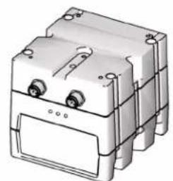
natural_image
3D rendering of a mechanical component with mounting holes and housing (no text or symbols visible)USB Module
Advanced Fluid Control Module

natural_image
Illustration of a rectangular electronic device with multiple ports and a side panel (no text or symbols)
natural_image
Illustration of a medical device with control buttons and display screen (no text or symbols)Display Module
Not all modules shown.
ti16440a


To help prevent fire and explosion, do not connect, download, or remove the token unless the unit is removed from the hazardous (explosive atmosphere) location.
NOTICE
To avoid damaging circuit board, wear a grounding strap.
- Use the token to load software to the Graco Control Architecture Module before use. Follow all directions and warnings in this manual and your system repair/parts manual.
- Upgrade token part numbers can be found in the system manual.
NOTE: Install software on the primary display of the system. All software may be able to be updated from the display, depending on system software and module series. See system manual for availability of this feature.
- Upgrade all modules in the system to the software version on the token, even if you are replacing only one or two modules. Different software versions may not be compatible.
- All data in the module may be reset to factory default settings. Record all settings and user preferences before the upgrade, for ease of restoring them following the upgrade.
- The latest software version for each system can be found at www.graco.com.
Supply Power to Module
Supply electrical power to the Graco Control Architecture module using either system power or Power Supply Kit 24F672, available separately.
Software Upgrade Instructions
Follow these instructions to upgrade the software in all of the Graco Control Architecture Modules. Reference illustrations of each module starting on page 6.
-
Remove power from the Graco Control Architecture Module by turning off system power or unplugging the Power Supply Kit 24F672 (available separately).
-
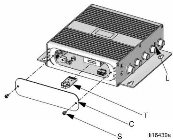
Remove access cover (C).
NOTE: For cube modules, the cover is removed by pressing in the two tabs. For other modules, one or more screws (S) must be removed.
- Insert and press the token (T) firmly into the slot.
NOTE: Token has no preferred orientation.
- Supply electrical power to the Graco Control Architecture Module using either system power or Power Supply Kit 24F672 (available separately).
NOTE: The Motor Control Module 257696, High Power Temperature Control Module 255774, and the Low Power Temperature Control Module 256270 do not require power to the high voltage AC input.
- The red indicator light (L) will flash while the software is being loaded. When the software is completely loaded, the red light will turn off.
NOTE: For the USB module only, when the red light stops flashing, the green and orange indicator lights adjacent to the USB connector will flash for several minutes while configurations are loaded. The software is completely loaded when the red, green, and orange indicator lights are off.
NOTE: For displays only: If is displayed on the
screen, see Remote Loading, page 3.
NOTICE
To prevent corrupting the software, do not remove the token, turn off the system power, or disconnect any modules until the status screen indicates that updates are complete.
- Remove power from the Graco Control Architecture Module by turning off system power or unplugging the Power Supply Kit 24F672.
- Remove the token (T) from the slot.
-
Reinstall the access cover and secure with screws (S), if applicable.
-
Upgrade all other modules in the system to the software revision on the token, if not already completed. Different software versions may not be compatible.
NOTE: If the software on the token is the same version that is already programmed on the module, nothing will happen (including flashing red light). No harm can be done by attempting to program the module multiple times. For Communications Gateway Modules, installing upgrade software will not erase or overwrite a data map, if already loaded.
Remote Loading
| Display on System Page | |
| Advanced Module (ADM), 24E451 | 3 |
| Display Module 262384, 24F493 | 4 |
| Display Control Module, 24L096, or Advanced Display Control Module, 24L097 | 5 |
Systems With Advanced Display Module (ADM), 24E451
- The following screen will be shown when the display turns on.

Communications with other modules established.
- Select which software is applied to each module when multiple software options exist. The following screen is not present in all systems. See system specific manual for more details. Press continue.

Key:
A Module Serial Number
B Software currently on module
C Software available for module
- Wait for update to complete.
NOTE: The approximate time until completion is shown along bottom of progress bar.

- Updates are complete. Icon indicates update success or failure. See Icon Table. Press continue.


bar
| Category | Value | |---|---| | 0054 | 10000 || Icon Description | |
| Update successful | |
| Update unsuccessful | |
| Update complete; no change necessary. | |
| Modules were updated or didn’t require an update; however, one or more modules need to be updated manually with a token. | |
Systems With A Display Module, 262384, 24F493
- The following screen will be shown when the display turns on.

Communications with other modules established.
- Select which software is applied to each module when multiple software options exist. The following screen is not present in all systems. See system
specific manual for more details. Press continue.

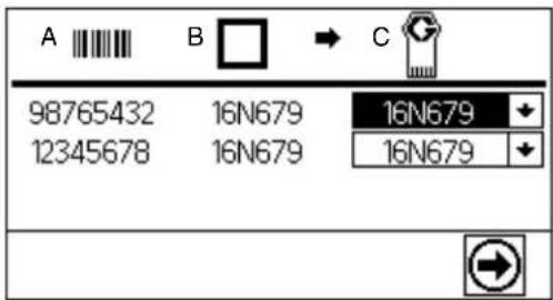
Key:
A Module Serial Number
B Software currently on module
C Software available for module
- Wait for update to complete.
NOTE: The approximate time until completion is shown along bottom of progress bar.
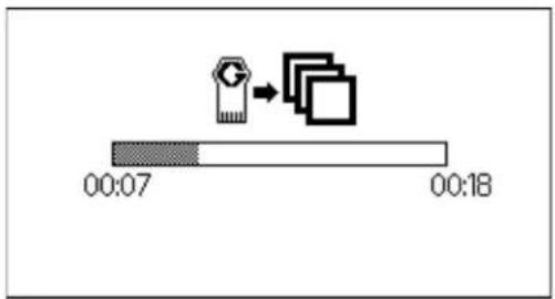
- Updates are complete. Icon indicates update
success or failure. See Icon Table. Press continue.


| Icon Description | |
 | Update successful |
 | Update unsuccessful |
 | Update complete; no change necessary. |
 | Modules were updated or didn't require an update; however, one or more modules need to be updated manually with a token. |
Systems With A Display Module or Advanced Display Module, 24L096, 24L097
- The following screen will be shown when the display turns on.

Communications with other modules established.
- Select which software is applied to each module when multiple software options exist. The following screen is not present in all systems. See system
specific manual for more details. Press continue.


Key:
A Module Serial Number
B Software currently on module
C Software available for module
- Wait for update to complete.
NOTE: The approximate time until completion is shown along bottom of progress bar.

- Updates are complete. Icon indicates update
success or failure. See Icon Table. Press continue.


flowchart
graph TD
    A["Document"] --> B["Check Table"]
    B --> C["Output"]
| Icon Description | |
 | Update successful |
 | Update unsuccessful |
 | Update complete; no change necessary. |
 | Modules were updated or didn't require an update; however, one or more modules need to be updated manually with a token. |
Available Graco Control Architecture Modules
Display Module (262384, 24F493)

Advanced Fluid Control Module (255920)
USB Module (289900)
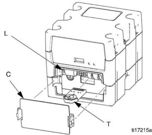
Advanced Display Module (24E451)

Communications Gateway Module (15V759, 15V760, 15V761, 15V762, 289835, 289836, 289837, 289838)

Discrete Gateway Module (24B681)
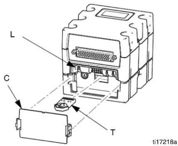
Fluid Control Module (289696)

Local Control Module (262416)
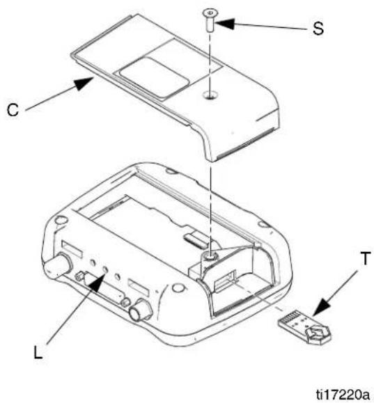
High Power Temperature Control Module (255774)
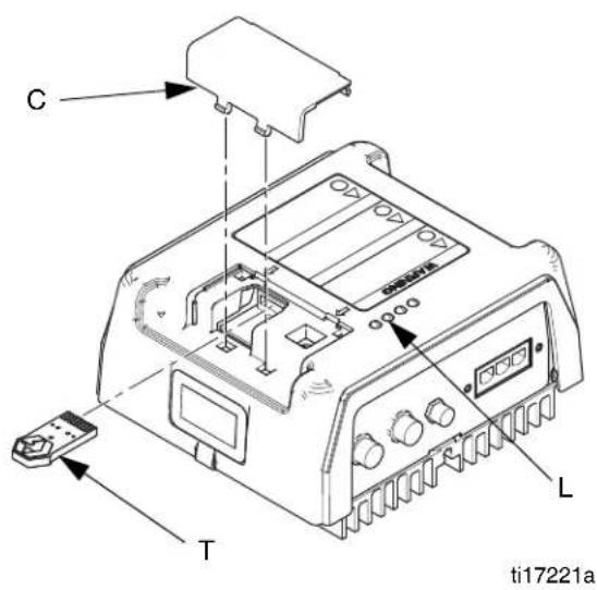
Low Power Temperature Control Module (256270)

Motor Control Module (257396)

Display Control Module (24L096) and Advanced Display Control Module (24L097)

Graco Standard Warranty
Graco warrants all equipment referenced in this document which is manufactured by Graco and bearing its name to be free from defects in material and workmanship on the date of sale to the original purchaser for use. With the exception of any special, extended, or limited warranty published by Graco, Graco will, for a period of twelve months from the date of sale, repair or replace any part of the equipment determined by Graco to be defective. This warranty applies only when the equipment is installed, operated and maintained in accordance with Graco's written recommendations.
This warranty does not cover, and Graco shall not be liable for general wear and tear, or any malfunction, damage or wear caused by faulty installation, misapplication, abrasion, corrosion, inadequate or improper maintenance, negligence, accident, tampering, or substitution of non-Graco component parts. Nor shall Graco be liable for malfunction, damage or wear caused by the incompatibility of Graco equipment with structures, accessories, equipment or materials not supplied by Graco, or the improper design, manufacture, installation, operation or maintenance of structures, accessories, equipment or materials not supplied by Graco.
This warranty is conditioned upon the prepaid return of the equipment claimed to be defective to an authorized Graco distributor for verification of the claimed defect. If the claimed defect is verified, Graco will repair or replace free of charge any defective parts. The equipment will be returned to the original purchaser transportation prepaid. If inspection of the equipment does not disclose any defect in material or workmanship, repairs will be made at a reasonable charge, which charges may include the costs of parts, labor, and transportation.
THIS WARRANTY IS EXCLUSIVE, AND IS IN LIEU OF ANY OTHER WARRANTIES, EXPRESS OR IMPLIED, INCLUDING BUT NOT LIMITED TO WARRANTY OF MERCHANTABILITY OR WARRANTY OF FITNESS FOR A PARTICULAR PURPOSE.
Graco's sole obligation and buyer's sole remedy for any breach of warranty shall be as set forth above. The buyer agrees that no other remedy (including, but not limited to, incidental or consequential damages for lost profits, lost sales, injury to person or property, or any other incidental or consequential loss) shall be available. Any action for breach of warranty must be brought within two (2) years of the date of sale.
GRACO MAKES NO WARRANTY, AND DISCLAIMS ALL IMPLIED WARRANTIES OF MERCHANTABILITY AND FITNESS FOR A PARTICULAR PURPOSE, IN CONNECTION WITH ACCESSORIES, EQUIPMENT, MATERIALS OR COMPONENTS SOLD BUT NOT MANUFACTURED BY GRACO. These items sold, but not manufactured by Graco (such as electric motors, switches, hose, etc.), are subject to the warranty, if any, of their manufacturer. Graco will provide purchaser with reasonable assistance in making any claim for breach of these warranties.
In no event will Graco be liable for indirect, incidental, special or consequential damages resulting from Graco supplying equipment hereunder, or the furnishing, performance, or use of any products or other goods sold hereto, whether due to a breach of contract, breach of warranty, the negligence of Graco, or otherwise.
FOR GRACO CANADA CUSTOMERS
For the latest information about Graco products, visit www.graco.com.
For patent information, see www.graco.com/patents.
TO PLACE AN ORDER, contact your Graco distributor or call to identify the nearest distributor.
Phone: 612-623-6921 or Toll Free: 1-800-328-0211 Fax: 612-378-3505
All written and visual data contained in this document reflects the latest product information available at the time of publication.
Graco reserves the right to make changes at any time without notice.
Original instructions. This manual contains English. MM 3A1244
Graco Headquarters: Minneapolis
International Offices: Belgium, China, Japan, Korea
GRACO INC. AND SUBSIDIARIES • P.O. BOX 1441 • MINNEAPOLIS MN 55440-1441 • USA
Copyright 2010, Graco Inc. All Graco manufacturing locations are registered to ISO 9001.
www.graco.com
Revision F, September 2016
- Important Safety Instructions
- NOTICE
- Supply Power to Module
- Software Upgrade Instructions
- Remote Loading
- Systems With Advanced Display Module (ADM), 24E451
- Systems With A Display Module, 262384, 24F493
- Key:
- Systems With A Display Module or Advanced Display Module, 24L096, 24L097
- Available Graco Control Architecture Modules
- Graco Standard Warranty
- THIS WARRANTY IS EXCLUSIVE, AND IS IN LIEU OF ANY OTHER WARRANTIES, EXPRESS OR IMPLIED, INCLUDING BUT NOT LIMITED TO WARRANTY OF MERCHANTABILITY OR WARRANTY OF FITNESS FOR A PARTICULAR PURPOSE.
- FOR GRACO CANADA CUSTOMERS
Brand : GRACO
Model : InSite 24T279
Category : Industrial electronic module