
IQ-USM 810 - Digital audio mixer CROWN - Free user manual and instructions
Find the device manual for free IQ-USM 810 CROWN in PDF.


| Product Type | Digital Processor / Digital Mixer |
| Brand | Crown |
| Model | IQ-USM 810 |
| Category | Professional Audio Control System Component |
| DSP Processing | 240 MIPS, 32-bit floating point |
| A/D & D/A Converters | 24-bit, 48 kHz sampling |
| Number of Inputs | 8 balanced (mic/line/phantom) |
| Number of Outputs | 2 main + 8 aux (balanced) |
| Control Interfaces | IQ Bus (RJ-45), RS232 (DB9F), Multi-Function Control Port (DB37M) |
| Front Panel Controls | SEL button, Up/Down arrows, Digital display |
| Presets | 32 user presets |
| Real-Time Clock | Yes, with 45-day backup capacitor |
| Event Scheduling | Yes, up to 32 events |
| Power Supply | Universal, 100-240 VAC, 50/60 Hz |
| Warranty | 3 years (No-Fault) |
| Mounting | 19-inch rack mountable |
Frequently Asked Questions - IQ-USM 810 CROWN
User questions about IQ-USM 810 CROWN
0 question about this device. Answer the ones you know or ask your own.
Ask a new question about this device
Download the instructions for your Digital audio mixer in PDF format for free! Find your manual IQ-USM 810 - CROWN and take your electronic device back in hand. On this page are published all the documents necessary for the use of your device. IQ-USM 810 by CROWN.
USER MANUAL IQ-USM 810 CROWN
Obtaining Other Language Versions: Obtaining Other Language Version page about the use of this product, please contact your local Crown Distributor. If you need assistance locating your local distributor, please contact Crown at 574-294-8000.
This manual does not include all of the details of design, production, or variations of the equipment. Nor does it cover every possible situation which may arise during installation, operation or maintenance.
The information provided in this manual was deemed accurate as of the publication date. However, updates to this information may have occurred. To obtain the latest version of this manual, please visit the Crown website at www.crownaudio.com

Trademark Notice: TrademacGro Noticaudio, IQ, IQ System and PZM are registered trademarks of Crown International. Other trademarks are the property of their respective owners.
Printed on Printed on recycled paper, recycled paper by Crown Audio®, Inc., P.O. Box 1000, Elkhart, Indiana 46515-1000 U.S.A. Telephone: 574-294-8000

THREE YEAR FULL WARRANTY

UNITED STATES & CANADA
WORLDWIDE EXCEPT USA & CANADA
SUMMARY OF WARRANTY
Crown International, 1718 West Mishawaka Road, Elkhart, Indiana 46517-4095 U.S.A. warrants to you, the ORIGINAL PURCHASER and ANY SUBSEQUENT OWNER of each NEW Crown product, for a period of three (3) years from the date of purchase by the original purchaser (the "warranty period") that the new Crown product is free of defects in materials and workmanship. We further warrant the new Crown product regardless of the reason for failure, except as excluded in this Warranty.
ITEMS EXCLUDED FROM THIS CROWN WARRANTY
This Crown Warranty is in effect only for failure of a new Crown product which occurred within the Warranty Period. It does not cover any product which has been damaged because of any intentional misuse, accident, negligence, or loss which is covered under any of your insurance contracts. This Crown Warranty also does not extend to the new Crown product if the serial number has been defaced, altered, or removed.
WHAT THE WARRANTOR WILL DO
We will remedy any defect, regardless of the reason for failure (except as excluded), by repair, replacement, or refund. We may not elect refund unless you agree, or unless we are unable to provide replacement, and repair is not practical or cannot be timely made. If a refund is elected, then you must make the defective or malfunctioning product available to us free and clear of all liens or other encumbrances. The refund will be equal to the actual purchase price, not including interest, insurance, closing costs, and other finance charges less a reasonable depreciation on the product from the date of original purchase. Warranty work can only be performed at our authorized service centers or at our factory. Warranty work for some products can only be performed at our factory. We will remedy the defect and ship the product from the service center or our factory within a reasonable time after receipt of the defective product at our authorized service center or our factory. All expenses in remedying the defect, including surface shipping costs in the United States, will be borne by us. (You must bear the expense of shipping the product between any foreign country and the port of entry in the United States including the return shipment, and all taxes, duties, and other customs fees for such foreign shipments.)
HOW TO OBTAIN WARRANTY SERVICE
You must notify us of your need for warranty service within the warranty period. All components must be shipped in a factory pack, which, if needed, may be obtained from us free of charge. Corrective action will be taken within a reasonable time of the date of receipt of the defective product by us or our authorized service center. If the repairs made by us or our authorized service center are not satisfactory, notify us or our authorized service center immediately.
DISCLAIMER OF CONSEQUENTIAL AND INCIDENTAL DAMAGES
YOU ARE NOT ENTITLED TO RECOVER FROM US ANY INCIDENTAL DAMAGES RESULTING FROM ANY DEFECT IN THE NEW CROWN PRODUCT. THIS INCLUDES ANY DAMAGE TO ANOTHER PRODUCT OR PRODUCTS RESULTING FROM SUCH A DEFECT. SOME STATES DO NOT ALLOW THE EXCLUSION OR LIMITATIONS OF INCIDENTAL OR CONSEQUENTIAL DAMAGES, SO THE ABOVE LIMITATION OR EXCLUSION MAY NOT APPLY TO YOU.
WARRANTY ALTERATIONS
No person has the authority to enlarge, amend, or modify this Crown Warranty. This Crown Warranty is not extended by the length of time which you are deprived of the use of the new Crown product. Repairs and replacement parts provided under the terms of this Crown Warranty shall carry only the unexpired portion of this Crown Warranty.
DESIGN CHANGES
We reserve the right to change the design of any product from time to time without notice and with no obligation to make corresponding changes in products previously manufactured.
LEGAL REMEDIES OF PURCHASER
THIS CROWN WARRANTY GIVES YOU SPECIFIC LEGAL RIGHTS, YOU MAY ALSO HAVE OTHER RIGHTS WHICH VARY FROM STATE TO STATE. No action to enforce this Crown Warranty shall be commenced after expiration of the warranty period.
THIS STATEMENT OF WARRANTY SUPERSEDES ANY OTHERS CONTAINED IN THIS MANUAL FOR CROWN PRODUCTS.
Visit www.crownaudio.com for a list of Crown authorized service centers.
Telephone: 574-294-8200. Facsimile: 574-294-8301
7/01
SUMMARY OF WARRANTY
Crown International, 1718 West Mishawaka Road, Elkhart, Indiana 46517-4095 U.S.A. warrants to you, the ORIGINAL PURCHASER and ANY SUBSEQUENT OWNER of each NEW Crown' product, for a period of three (3) years from the date of purchase by the original purchaser (the "warranty period") that the new Crown product is free of defects in materials and workmanship, and we further warrant the new Crown product regardless of the reason for failure, except as excluded in this Warranty.
^1 Note: If your unit bears the name "Amcron," please substitute it for the name "Crown" in this warranty.
ITEMS EXCLUDED FROM THIS CROWN WARRANTY
This Crown Warranty is in effect only for failure of a new Crown product which occurred within the Warranty Period. It does not cover any product which has been damaged because of any intentional misuse, accident, negligence, or loss which is covered under any of your insurance contracts. This Crown Warranty also does not extend to the new Crown product if the serial number has been defaced, altered, or removed.
WHAT THE WARRANTOR WILL DO
We will remedy any defect, regardless of the reason for failure (except as excluded), by repair, replacement, or refund. We may not elect refund unless you agree, or unless we are unable to provide replacement, and repair is not practical or cannot be timely made. If a refund is elected, then you must make the defective or malfunctioning product available to us free and clear of all liens or other encumbrances. The refund will be equal to the actual purchase price, not including interest, insurance, closing costs, and other finance charges less a reasonable depreciation on the product from the date of original purchase. Warranty work can only be performed at our authorized service centers. We will remedy the defect and ship the product from the service center within a reasonable time after receipt of the defective product at our authorized service center.
HOW TO OBTAIN WARRANTY SERVICE
You must notify your local Crown importer of your need for warranty service within the warranty period. All components must be shipped in the original box. Corrective action will be taken within a reasonable time of the date of receipt of the defective product by our authorized service center. If the repairs made by our authorized service center are not satisfactory, notify our authorized service center immediately.
DISCLAIMER OF CONSEQUENTIAL AND INCIDENTAL DAMAGES YOU ARE NOT ENTITLED TO RECOVER FROM US ANY INCIDENTAL DAMAGES RESULTING FROM ANY DEFECT IN THE NEW CROWN PRODUCT. THIS INCLUDES ANY DAMAGE TO ANOTHER PRODUCT OR PRODUCTS RESULTING FROM SUCH A DEFECT.
WARRANTY ALTERATIONS
No person has the authority to enlarge, amend, or modify this Crown Warranty. This Crown Warranty is not extended by the length of time which you are deprived of the use of the new Crown product. Repairs and replacement parts provided under the terms of this Crown Warranty shall carry only the unexpired portion of this Crown Warranty.
DESIGN CHANGES
We reserve the right to change the design of any product from time to time without notice and with no obligation to make corresponding changes in products previously manufactured.
LEGAL REMEDIES OF PURCHASER
No action to enforce this Crown Warranty shall be commenced after expiration of the warranty period.
THIS STATEMENT OF WARRANTY SUPERSEDES ANY OTHERS CONTAINED IN THIS MANUAL FOR CROWN PRODUCTS.
Visit www.crownaudio.com for a list of Crown authorized service centers.
12/01
Telephone: 574-294-8200. Facsimile: 574-294-8301
Important Safety Instructions
1) Read these instructions.
2) Keep these instructions.
3) Heed all warnings.
4) Follow all instructions.
5) Do not use this apparatus near water. Do not expose to dripping or splashing. Do not place objects filled with liquid on unit.
6) Clean only with a dry cloth.
7) Do not block any ventilation openings. Install in accordance with the manufacturer's instructions.
8) Do not install near any heat sources such as radiators, heat registers, stoves, or other apparatus that produce heat.
9) Do not defeat the safety purpose of the polarized or grounding-type plug. A polarized plug has two blades with one wider than the other. A grounding-type plug has two blades and a third grounding prong. The wide blade or the third prong is provided for your safety. If the provided plug does not fit into your outlet, consult an electrician for replacement of the obsolete outlet.
10) Protect the power cord from being walked on or pinched, particularly at plugs, convenience receptacles, and the point where they exit from the apparatus.
11) Only use attachments/accessories specified by the manufacturer.
12) Use only with a cart, stand, bracket, or table specified by the manufacturer, or sold with the apparatus. When a cart is used, use caution when moving the cart/apparatus combination to avoid injury from tip-over.
13) Unplug this apparatus during lightning storms or when unused for long periods of time.
14) Refer all servicing to qualified service personnel. Servicing is required when the apparatus has been damaged in any way, such as power-supply cord or plug is damaged, liquid has been spilled or objects have fallen into the apparatus, the apparatus has been exposed to rain or moisture, does not operate normally, or has been dropped.
15) To reduce the risk of electric shock, do not expose this equipment to rain or moisture.


The information furnished in this manual does not include all of the details of design, production, or variations of the equipment. Nor does it cover every possible situation which may arise during installation, operation or maintenance. If you need special assistance beyond the scope of this manual, please contact our Customer Service.
Crown Customer Service
Technical Support/Factory/Sepidney Service
1718 W. Mishawaka Rd., Elkhart, Indiana 46517 U.S.A.
Phone: 800-342-6939 (North America, Puerto Rico and Virgin Islands) or 574-294-8200
Fax: 574-294-8301 Internet: http://www.crownaudio.com email: iqsupport@crownintl.com

WARNING
TO REDUCE THE RISK OF ELECTRIC SHOCK, DO NOT EXPOSE THIS EQUIPMENT TO RAIN OR MOISTURE!
PLEASE NOTE
The following universal symbols may appear on your product and/or in various sections of this manual. Wherever they appear, they are to be interpreted as follows:

Lightning Bolt Symbol:
This symbol is used to alert the user to the presence of dangerous voltages and the possible risk of electric shock.

Exclamation Mark Symbol:
This symbol is used to alert the user to refer to the instruction manual for important operating or maintenance instructions.
FCC Class B Compliance
This equipment has been tested and found to comply with the limits for Class B Digital Device, pursuant to Part 15 of the FCC rules. These limits are designed to provide reasonable protection against harmful interference in a residential installation. This equipment generates, uses and can radiate radio frequency energy and, if not installed and used in accordance with the instructions, may cause harmful interference to radio communications. However, there is no guarantee that interference will not occur in a particular installation. If this equipment does cause harmful interference to radio or television reception, which can be determined by turning the equipment off and on, the user is encouraged to try to correct the interference by one or more of the following measures:
– Reorient or relocate the receiving antenna.
– Increase the separation between the equipment and receiver.
- Connect the equipment into an outlet on a circuit different from that to which the receiver is connected.
- Consult the dealer or an experienced radio/TV technician for help.
Quick Install Procedure
This procedure is provided for those who are already familiar with Crown's IQ System and would like to install the IQ-USM 810 in the shortest time possible. Less experienced installers or those wishing a full explanation of the installation procedure are encouraged to refer to Section 3.
Prepare the IQ-USM 810:
1 Set the IQ address (Section 3.2.1) on the IQ-USM 810 to an unused IQ address.
2 If the unit is to be used as a system interface, set the baud rate, and set the unit to act as system interface (green Interface LED on).
Mounting:
3 Mount the unit into a standard 19-inch (48.3-cm) equipment rack or cabinet, or it can be stacked.
Install the wiring:
4 Connect the IQ-USM 810 to the IQ System via the IQ Bus, or directly to the host computer if the unit is to be used as the system interface or stand-alone (see Section 3.1).
5 Turn off all amplifiers or other equipment that will either feed or be connected to the unit.
6 Connect the audio wiring to the IQ-USM 810 inputs and outputs.
7 Connect the IQ Bus wiring to all components if the unit is to be used as the system interface (see Section 3.2.2).
8 Connect any circuits to be used with the Control Port connector to the unit.
9 Connect the unit to the AC receptacle.
Prepare the audio system:
10 Set all equipment that will be in the signal chain before or after the IQ-USM 810.
11 Set and verify all level and gain settings on all amplifiers or other equipment that will either feed or be connected to the unit.
Configure the IQ-USM 810:
12 Set input selector switches for Mic, Line, or Phantom, depending upon input signal to be fed to the input.
13 Set gain levels on the back of the unit.
CONTENTS
Quick Install Procedure .... 5
1 Welcome 8
1.1 Unpacking 8
2 Controls, Connectors & Indicators 9
3 Hardware Installation .... 10
3.1 Connecting to a Host Computer 10
3.1.1 Set the Baud Rate 11
3.2 Connecting to the IQ Bus 11
3.2.1 Set the IQ Address Switch 11
3.2.2 Connect to the IQ System via the IQ Bus 12
3.3 Connect the Audio Wiring 12
3.4 Connect Auxiliary Devices 13
4 Operation 14
4.1 Hardware Features 14
4.1.1 Selector Buttons 14
4.1.2 Digital Display 14
4.1.3 Enable Indicator 14
4.1.4 DATA Indicator 14
4.1.5 Interface Indicator 14
4.1.6 Input Gate Status Display.... 15
4.1.7 Audio Inputs 15
4.1.8 Input Selector 15
4.1.9 Audio Input Gain Control 15
4.1.10 Main Audio Outputs 15
4.1.11 AUX Audio Outputs 15
4.1.12 IQ Bus Input/Output Connector 15
4.1.13 IQ Bus Output Connector 15
4.1.14 RS232 Serial Port 15
4.1.15 Multi-Function Control Port Connector 15
4.1.16 AC Line Connector 15
4.2 General Firmware Features 15
4.2.1 Input Level Meters 15
4.2.2 Input Dynamic Cut/Boost Meters 15
4.2.3 Output Level Meters 16
4.2.4 Output Dynamic Cut/Boost Meters 16
4.2.5 Memory Backup 16
4.2.6 Presets 16
4.2.7 Real Time Clock 16
4.2.8 Events 16
4.3 Input Signal Processing.... 16
4.3.1 Input Filters 16
4.3.2 Input Processing Delay 18
4.3.3 Input Gate 18
4.3.4 Auto-Leveler 19
4.3.5 Input Compressor 19
4.3.6 Automixing 20
4.3.7 A/B Processing Section Filters 21
4.3.8 Input Signal Muter/Inverter 21
4.4 Matrix Mixer 21
4.4.1 Input Solo 21
4.4.2 Main A/B Mix Bus Faders 21
4.4.3 Aux Mix Bus Input Selectors 21
4.4.4 AUX Mix Bus Faders 22
4.5 Output Signal Processing 22
4.5.1 Output Delay 22
4.5.2 Output Filters 22
4.5.3 Ambient Leveler 22
4.5.4 Main Output Faders 22
4.5.5 AUX Output Faders 22
4.5.6 Output Limiter 22
4.5.7 Output Muter/Inverter 23
4.6 Multi-Function Control Port 23
4.6.1 Logic Digital Inputs (DIN 1-8) 23
4.6.2 Analog Inputs (AIN 1-8) 23
4.6.3 Digital Outputs 24
5 Technical Information 25
5.1 Technical Description 25
5.1.1 Audio 25
5.1.2 Control and Interface 25
5.2 Specifications 27
6 Working With IQ....30
6.1 A Closer Look at Audio Signal Wiring 30
6.1.1 Input 30
6.1.2 Output 31
6.2 Using the Multi-Function Control Port 32
6.2.1 Control Port Outputs 32
6.2.2 Control Port Analog Inputs 33
6.2.3 Control Port Digital Inputs 33
6.3 Working with RJ-45 Connectors 34
6.4 A Closer Look at IQ Bus Wiring 34
6.5 The IQ-USM 810 as a 1-Loop Interface 34
6.6 IQ Bus Wiring with a Patch Panel 35
7 Service 36

Figure 1.1 The IQ-USM 810
1 Welcome
Thank you for purchasing the Crown ^ IQ-USM 810. The IQ-USM 810 is a true 8x10 mixer that also provides very unique dual input processing paths, making it two complete eight-channel mixers in one chassis. In addition, every input and output channel includes a full complement of signal processing as well as auto-mixing features to offer a complete “system-in-a-box” solution. As an IQ ^ component, it can be controlled by an IQ System ^ , and with its distributed intelligence ^TM capability, continue to operate even when an IQ System is not connected. The IQ-USM 810 can also act as a system interface to other IQ components.
The IQ-USM 810 features high-quality 24-bit A/D and D/A converters along with 240MIPS of full 32-bit floating point DSP for optimum dynamic range.
Each of the eight balanced inputs is fully adjustable for any mic- or line-level source and is processed through adjustable signal delay and filtering before being split into the two separate "A/B" Processing Sections. The A/B Processing Sections include advanced algorithms for gating, auto-leveling, filtering, compression and automixing. Automixing functions include NOM (Number of Open Mics) Attenuation, Priority Ducking, and Adaptive Gating processing. Each of the sixteen A/B Processing Sections is then processed by a full 8x8 Matrix Mixer that allows any combination of routing and mixing from any input to any output. The Matrix Mixer outputs are routed to eight AUX Audio Outputs. The Main and AUX Audio Output sections further process the signal with individually adjustable signal delay and filters along with an Ambient-Leveler and a high performance Output Limiter for system protection.
All of the IQ-USM 810 parameters are backed up via reliable FLASH Memory. System configurations may be stored for recall from any of thirty-two system presets from the front panel control or via IQ for Windows software. The unit is controllable by IQ for Windows software (version 4.1 or later) via IQ Bus, standard RS-232 serial port, or over Ethernet (with IQNET Server software). It may also be controlled by third-party system controllers from companies such as AMX and Crestron. A Multi-Function Control Port implements analog and digital I/O for control and monitor by simple potentiometer and switch wall controllers and indicator panels.
This manual will help you successfully install your unit, and describes the capabilities of the IQ-USM 810. Please read all the instructions, warnings and cautions contained within it. Consult the IQ for Windows software documentation for descriptions of the software controls for this unit. Also, for your protection, please send in the warranty registration card today. And save the bill of sale—it is your official proof of purchase.
1.1 Unpacking
Please inspect the unit for any damage that may have occurred during transit. If damage is found, notify the transportation company immediately. Only you, the consignee, may initiate a claim with the carrier for shipping damage. Crown will cooperate fully as needed. Save the shipping carton as evidence of damage for the shipper's inspection.
Please save all packing materials. NEVER SHIP THE UNIT WITHOUT THE FACTORY PACK.

2 Controls, Connectors & Indicators


Figure 2.1 IQ-USM 810 Controls, Connectors & Indicators

flowchart
graph TD
    A["Laptop"] --> B["RS232"]
    B --> C["CROWN MICROTECH R402"]
    C --> D["IQ BUS LOOP"]
    D --> E["Server 1"]
    D --> F["Server 2"]
    D --> G["Server 3"]
    D --> H["Server 4"]
Figure 3.1 An IQ System with a Host Computer and a IQ-USM 810
3 Hardware Installation
The installation of an IQ-USM 810 consists of installing the hardware and configuring the unit via IQ for Windows software. Refer to the IQ for Windows Help files for instructions in setting up and operating your IQ software.
The hardware installation is divided into 4 major steps: 1) connecting to a host computer; 2) connecting to the IQ Bus; 3) connecting the audio inputs and outputs and; 4) connecting auxiliary devices
3.1 Connecting to a Host Computer (Step 1)
An IQ host computer is an IBM® PC-compatible computer which is used to configure or control/monitor an IQ System. Depending upon the design of your IQ System, it may or may not require a host computer during normal operation.
How the IQ-USM 810 will be used will determine whether or not it will need to be connected directly to a host computer. If the unit will be connected to the IQ Bus it will not need to be connected directly to a host computer. The following circumstances require connection to a host computer:
- If an IQ Bus will not be used, the IQ-USM 810 will need to be connected to a host computer so the firmware inside the unit can be configured. Afterwards, if computer control is not required, the host computer can be disconnected.
- If the IQ-USM 810 must be configured before it is installed into an IQ System, it must be connected directly to a host computer for configuration. The onboard memory of the unit will maintain its software configuration without it being plugged into an AC source.
- If the IQ-USM 810 will be used as an IQ interface for other IQ System components, it will need to be connected directly to a host computer for configuration of other components during setup, and for IQ control of components during normal operation.
One of the advantages of connecting directly to a host computer is that a separate IQ interface (IQ-INT-I) is not required. If you plan to configure the unit while it is connected to the IQ Bus, skip ahead to Section 3.2.
RS232 is commonly used with IBM PCs and compatibles, and is the communication standard supported by the IQ-USM 810 when used as an interface. Because it uses unbalanced signal wiring, it cannot be
used for distances over 50 feet (15.2 m).
The following illustration shows how to wire the serial cable:
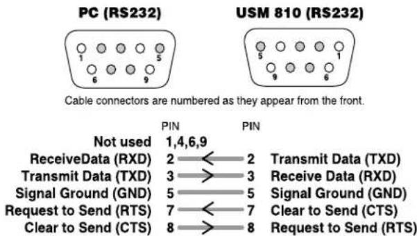
Figure 3.2 RS232 Cable Wiring
Important: Do not use twisted pair wire for RS232 because it increases crosstalk. Instead, use an un-twisted cable or ribbon cable.
Baud rate for RS232 serial communication is set using the front panel buttons shown in Figure 2.1. IQ for Windows software has the capability to adjust automatically to the baud rate of the IQ-USM 810 for maximum performance, so setting the baud rate usually is not necessary; however, the baud rate can be set by using the following procedure:
3.1.1 Set the Baud Rate
To set the baud rate, push and hold the front-panel SEL button (see Figure 2.1) until the display changes first to address select mode, then to baud rate select mode. Then push the up or down arrow buttons to select the desired baud rate. The highest baud rate supported by the unit is 115 K baud.*
When the SEL button is released, the user has two seconds to begin using the up or down arrow buttons before the display changes back to default. When the parameter is adjusted to the desired value, press the SEL button again to store the setting.
The communication parameters of the host computer are set within IQ for Windows software. Please refer to the IQ for Windows Help files for information about setting up communication parameters.
Here are some steps to follow if you are having difficulty establishing serial communication:
- If the host computer fails to communicate with the unit and the communication standard and parameters are set correctly, try reducing the baud rate.
- Check the serial cable for improper wiring or possible shorted or broken wires.
- If communication problems persist, check for other programs or hardware in the computer that might interfere.
- For further assistance contact the Crown Technical Support Group (see Section 7 for contact information.)
3.2 Connecting to the IQ Bus (Step 2)
The IQ Bus is a serial communication loop for transmitting IQ commands and data. It provides excellent flexibility, allowing an IQ Bus loop to be wired with either fiber optic cabling or with inexpensive twisted-pair wire. A single IQ System can have more than one IQ Bus loop. To function properly, an IQ Bus loop must be unbroken.
By giving every IQ component a unique address per IQ loop, each can be individually controlled and monitored.
3.2.1 Set the IQ Address
To set the address, push and hold the front-panel SEL button (see Figure 2.1) until the display changes to address select mode, then push the up or down buttons to select the desired address number. Press the SEL button again to store the address. The display will automatically return to preset display mode in a few seconds.
An IQ address can be any number from 1 to 250.* No two IQ components of the same type which are connected to the same IQ Bus can have the same address. Suppose, for example, an IQ System has two IQ Bus loops, 1 and 2, and a IQ-USM 810 is to be installed into loop 1 and given an address of 114. No other IQ-USM 810 can be given the same address in loop 1. However, a IQ-USM 810 in loop 2 can have the address of 114, and another type of IQ component can be given an address of 114 in loop 1. For example, both an IQ-PIP-USP2 and a IQ-USM 810 can use address 114 in loop 1 or any other loop.
3.2.2 Connect the IQ-USM 810 to the IQ System via the IQ Bus
The IQ components in an IQ Bus loop are wired sequentially. The loop begins and ends with the IQ interface. The output of one IQ component "loops" to the input of the next and so on as shown in Figure 3.9.
Three different types of connectors are used for IQ Bus wiring on IQ components. These include DIN connectors, RJ-45 connectors, and removable barrier strip plugs. The IQ-USM 810 uses RJ-45 connectors that accept plugs like the one shown in Figure 3.3.
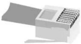
Figure 3.3 RJ-45 Plug
The following examples show how to connect the IQ-USM 810 to other IQ components on the IQ Bus:

Figure 3.4 RJ-45 Output to Barrier Block Input

Figure 3.5 RJ-45 Output to Din Input

Figure 3.6 Barrier Block Output to RJ-45 Input

Figure 3.7 Din Output to RJ-45 Input

Figure 3.8 RJ-45 Output to RJ-45 Input
3.3 Connect the Audio Wiring (Step 3)
The IQ-USM 810 has eight mic/line inputs, two main outputs and eight AUX outputs Three-terminal removable barrier block connectors are provided for the mic/ line inputs and main and AUX outputs. See Section 6.1 for information on the operation of the IQ-USM 810 inputs and outputs.

Figure 3.9 IQ Bus Wiring "Loop" from Output to Input of Each IQ Component
3.4 Connect Auxiliary Devices (Step 4)
Connect any external circuits you plan to use to control and/or monitor the IQ-USM 810 via the Control Port. Figure 3.10 shows pin assignments for the Control Port. See Section 6.2 for information on the operation of the Control Port, and for examples of wiring circuits to the Control Port connector.
USM 810 Control Port (DB37)

Figure 3.10 Control Port Pin Assignment
4 Operation
The Crown IQ-USM 810 digital processor/digital mixer is an IQ component that can be controlled and monitored from a remote location via an IQ System, and provides both audio processing and mixing in a single package. Metering, gain, gating, filtering, autoleveling, compression/limiting, delay, and automixing are all available in an 8-IN/10-OUT mix matrix. All inputs have low noise microphone preamps and switched phantom power. The unit can be controlled using IQ for Windows either directly from a computer or as an IQ component on an IQ Bus. The Multi-Function Control Port allows external control or monitoring of functions within the box. An internal Real Time Clock allows full functional presets to be scheduled and implemented without any external control.
The following sections describe the IQ-USM 810's features and their operation. Where specified, some features are accessed via controls located on the unit itself; however, most of the features are configured and controlled using IQ for Windows software. If you are unfamiliar with IQ for Windows software, please refer to the IQ for Windows Help files, visit the Crown Audio website, or contact your Crown representative or the Crown Technical Support Group (see Section 7 for contact information).
4.1 Hardware Features
4.1.1 Selector Buttons
Three front panel buttons (Figure 4.1) are provided to select presets and to change address and baud rate. The SEL button, when pressed and held for longer than 2 seconds, causes the display to cycle through the available choices until it is released; first to address select mode, then to baud rate select mode, then back to preset select mode. Once the SEL button is released, the up and down arrow buttons are used to adjust each parameter. When the SEL button is released, the user has two seconds to begin using the up or down arrow buttons before the display changes back to default. When the parameter is adjusted to the desired value, press the SEL button again to store the setting. See Section 3.1 for information about selecting IQ address and baud rate. Front panel control may be locked out via IQ for Windows software.*
4.1.2 Digital Display
The three-segment digital display (Figure 4.1) serves several useful functions. When power is first applied, it displays an initialization sequence. Once the unit is initialized, the display changes to Preset Mode, indicating the presently selected preset. The display also indicates the IQ address and baud rate when those parameters are being adjusted. When a parameter is changed, a small indicator (letter A in Figure 4.1) momentarily lights to show the parameter has been stored in FLASH memory. Another small indicator (letter B in Figure 4.1) is lit whenever any parameter is varied from its value within the currently selected preset.

Figure 4.1 Selector Buttons and Digital Display
See Section 2 for locations of the following hardware features and controls.
4.1.3 Enable Indicator
A blue front panel Enable indicator lights to show that AC power is being supplied.
4.1.4 DATA Indicator
An amber front panel Data Signal Presence Indicator (DATA) flashes whenever commands addressed to the IQ-USM 810 are received. To assist with troubleshooting, an option that forces the DATA indicator to remain lit is available through IQ for Windows software.
4.1.5 Interface Indicator
A green front panel Interface indicator lights when the IQ-USM 810 is being used as a system interface. The control to set the IQ-USM 810 as an interface is available through IQ for Windows software, allowing only one interface per system.
4.1.6 Input Gate Status Display
A sixteen-segment LED display matrix is provided on the front panel. The LEDs are separated into two rows labeled "A" and "B." The display can be set to three different operating modes: Level Meter, Gate Status, and Infinity Pattern (LED test mode). In the Level Meter mode, each row can be set to display the signal level of any input or output meter. In Gate Status mode, each LED represents a corresponding input gate, and remains lit while the gate is open. In Infinity Pattern mode, the LEDs constantly flash in an "figure-eight" pattern.
4.1.7 Audio Inputs
Three-terminal removable barrier block connectors are provided on the rear panel for balanced audio input.
4.1.8 Input Selector
Each input has a three-position M/L/P selector switch for mic level, line level, or mic level with phantom power. Select the left position (M) for microphone signal levels up to +7 dBu (0 dBu = 0.775 volts). Select the center position (L) for line level signals up to +32 dBu. Select the right position (P) to provide +24VDC to mics requiring phantom power.
4.1.9 Audio Input Gain Control
Each input channel has a screwdriver-set, calibrated gain potentiometer for adjusting the input gain to the input signal level. They can be used to compensate for different microphone sensitivities (see Section 6.1.1 for information on setting up the input gain controls). Control range is from -12 dB to +20 dB.
4.1.10 Main Audio Outputs
A 3-pin removable barrier block plug is provided on the rear panel for each main output.
4.1.11 AUX Audio Outputs
A 3-pin removable barrier block plug is provided on the rear panel for each AUX audio output. Any combination of inputs can be routed to each AUX audio output.
4.1.12 IQ Bus Input/Output Connector
The upper rear panel RJ-45 connector provides both input and output connection to the IQ Bus. This connector is used for input in a conventional IQ Bus wiring configuration, and can be used for both input and output when a "hub" style IQ Bus wiring configuration is implemented (see Section 6.6). Drop-out relays maintain loop integrity in the event power is removed from the IQ-USM 810.
4.1.13 IQ Bus Output Connector
The lower rear panel RJ-45 connector provides for normal output wiring to the next device on the IQ Bus loop.
4.1.14 RS232 Serial Port
A female DB9 serial port connector is provided on the rear panel for direct communication with a PC serial port. The IQ-USM 810 is capable of serving as the system interface for other IQ components (see Section 3.1).
4.1.15 Multi-Function Control Port
A male DB37 connector is provided on the rear panel for external monitoring and control of objects within the IQ-USM 810. There are sixteen digital outputs, eight digital inputs and eight analog inputs available as well as +5V and +10V for powering external circuits. Section 6.2 gives pin assignments, electrical specifications and application examples for the Multi-Function Control Port.
4.1.16 AC Line Connector
A rear panel IEC320 connector is provided for attaching the power cord. The IQ-USM 810 has a universal power supply, and may be operated on AC line voltages from 100VAC to 240VAC at 50Hz or 60Hz.
4.2 General Firmware Features
Note: The following features are accessed via IQ for Windows software unless otherwise stated. Refer to Figure 5.2, IQ-USM 810 Signal Flow Block Diagram for feature locations in the audio signal chain.
4.2.1 Input Level Meters
Audio level peak program meters are provided for each input. The meters sense the audio signal immediately after analog to digital conversion, and respond with 1.7 millisecond attack and 350 millisecond release. Meter range is from -60 to +20 dBu with 12 -dB resolution. Calibration is in dBu when the input is in "line" mode and set at 0 dB.
4.2.2 Input Dynamic Cut/Boost Meters
Meters are provided for each Input A/B Processing Section to indicate the overall cut or boost being applied from all signal processing features that affect input gain, including Auto-Leveler, Input Compressor, and Auto-Mixing. Meter range is from -60 to +20 dBu with 12 -dB resolution.
4.2.3 Output Level Meters
Audio level meters are provided for each output. The meters sense the audio signal immediately after the audio output processing block, and respond with 1.7-millisecond attack and 350-millisecond release. Meter range is from -60 to +20 dBu with 12 -dB resolution.
4.2.4 Output Dynamic Cut/Boost Meters
Meters are provided for each output to indicate the overall cut or boost being applied from all signal processing features that affect output gain, including Ambient-Level and Output Limiter. Meter range is from -60 to +20 dBu with 12 -dB resolution.
4.2.5 Memory Backup
The IQ-USM 810 settings are stored in high-endurance flash memory whenever a parameter is changed. changed settings are updated every few seconds.
4.2.6 Presets
The parameters for all functions within the IQ-USM 810 can be saved as presets and each can be given a unique 32-character name. A total of 32 user presets can be stored in the IQ-USM 810's flash memory. Presets can be recalled via the front-panel selector buttons, IQ for Windows preset selector controls, from within events, or by an external system controller via the Multi-Function Control Port.
- Preset Segue: When a preset is selected, the Preset Segue feature provides a smooth transition to the new preset. Preset Segue can be set to either a fixed time in seconds or a fixed rate in dB per second. Range for fixed time in seconds is 1 to 255 seconds. Range for fixed rate in dB per second is from 0.5 dB to 40 dB.
4.2.7 Real Time Clock
The onboard Real Time Clock tracks day, date, hour, minute and second, and may be set to any date and time desired, or to match that of the computer running IQ for Windows software. The clock is used as a time reference for the Events Scheduling feature. Internal capacitor storage allows the clock to run for up to 45 days without power being applied to the IQ-USM 810.
4.2.8 Events
User presets can be scheduled for recall as an Event at a specific date and time, and also can be set to repeat. A total of 32 Events can be scheduled, and each Event can be given a unique 32-character name.
4.3 Input Signal Processing
Note: The following features are controlled and monitored via IQ for Windows software. Refer to Figure 5.2, IQ-USM 810 Signal Flow Block Diagram for feature locations in the audio signal chain.
4.3.1 Input Filters
The input signal can be filtered with any combination of up to eight different filter types. Different filter types include the following:
Low-Pass Crossover Filter (1st-4th order)
High-Pass Crossover Filter (1st-4th order)
Parametric Equalization Filter (2nd order only)
Low-Pass Equalization Filter (2nd order only)
High-Pass Equalization Filter (2nd order only)
High-Pass Shelving Equalization (1st order only)
All-Pass Filter
32 filters per DSP processor are available for a total of 128 filters within the IQ-USM 810. An indicator in IQ for Windows software shows how much of the DSP resources are being used by the selected filters.
The chart in Figure 4.2 shows how processing is allocated to each of the four DSP processors.
| DSP 0 | DSP 1 | DSP 2 | DSP 3 |
| • Inputs 1–4 (filters 1–32) | • Inputs 5–8 (filters 33–64) | • Aux 1–4 & Main A (filters 65–96) • Mixing for Aux 1–4 & Main A | • Aux 5–8 & Main B (filters 97–128) • Mixing for Aux 5–8 & Main B |
Figure 4.2 DSP Processor Allocation
One 3rd- or 4th-order filter uses the equivalent of two 1st- or 2nd-order filters.
1st-, 2nd-, 3rd- and 4th-order responses result in 6-, 12-, 18- and 24-dB/octave roll-offs, respectively.
All filters with adjustable Q-factors can be set in fractions of an octave.
All filters have IIR-based topologies to ensure a proper magnitude/phase relationship for use in professional audio applications such as equalizer or crossover (dividing) networks.
Low-Pass Crossover Filter
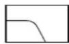
Description: This filter rolls off high frequencies at a rate determined by the shape parameter. The filter is commonly used to feed the low-frequency portion of an audio signal to woofers or subwoofers. It can be combined with a high-pass crossover filter to create a band-pass crossover filter for driving mid-range drivers.
Passband gain: Sets the amount of boost or cut for the filter. Control range is +24 dB to -24 dB in ^1/2 -dB steps.
Frequency: Sets the -3-dB corner frequency of the filter. Control range is 20 Hz to 20 kHz in 1-Hz increments.
Shape: Sets the response shape of the filter. Available response shapes are: 1st-order Butterworth, 2nd-order Butterworth, 3rd-order Butterworth, 4th-order Butterworth, 2nd-order Bessel, 3rd-order Bessel, 4th-order Bessel and 4th-order Linkwitz-Riley.
High-Pass Crossover Filter
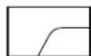
Description: This filter rolls off low frequencies at a rate determined by the shape parameter. The filter is commonly used to feed the high-frequency portion of an audio signal to horns or tweeters. It can be combined with a low-pass crossover filter to create a band-pass crossover filter for driving mid-range drivers.
Passband gain: Sets the amount of boost or cut for the filter. Control range is +24 dB to -24 dB in ^1/2 -dB steps.
Frequency: Sets the -3-dB corner frequency of the filter. Control range is 20 Hz to 20 kHz in 1-Hz increments.
Shape: Sets the response shape of the filter. Available response shapes are: 1st-order Butterworth, 2nd-order Butterworth, 3rd-order Butterworth, 4th-order Butterworth, 2nd-order Bessel, 3rd-order Bessel, 4th-order Bessel and 4th-order Linkwitz-Riley.
Parametric Equalization Filter
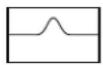
Description: This filter boosts or cuts a relatively narrow frequency band like a band-pass filter. It is commonly used to correct specific anomalies in the response of drivers.
Passband Gain: Sets the amount of boost or cut for the filter. Control range is +24 dB to -24 dB in 12 -dB steps.
Frequency: Sets the center frequency of the filter. Control range is 20 Hz to 20 kHz in 1 Hz increments.
Octave Bandwidth: Sets the width and slope, or "Q" of the filter (see Figure 4.1). The lower the Q, the wider the filter and the better the transient response and visa versa. Control range is from 0.0416 ( ^1/24 octave) to 6.667 ( ^6/3 octave) in 0.0416 ( ^1/_24 -octave) increments.
CAUTION: Avoid excessive Qs.*
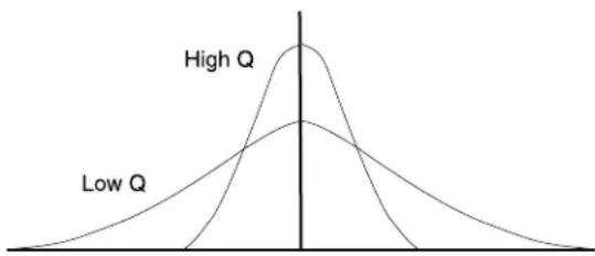
line
| Category | Peak Value | | -------- | ---------- | | High Q | High | | Low Q | Low |Figure 4.1 Effect of Q-Factor on Filter Response
Low-Pass Equalization Filter

Description: This filter combines the functions of the parametric equalization filter to boost or cut a relatively narrow frequency band with a low-pass filter to roll of the frequencies above the center frequency. ^**
Passband Gain: Sets the amount of boost or cut for the filter. Control range is +24 dB to -24 dB in 12 -dB steps.
Frequency: Sets the center frequency of the filter. Control range is 20 Hz to 20 kHz in 1Hz increments.
Octave Bandwidth: Sets the width and slope, or "Q" of the filter (see Figure 4.1). The lower the Q, the wider the filter and the better the transient response and visa versa. Control range is from 0.0416 ( 1/24 octave) to 6.667 ( 6^2/3 octave) in 0.0416 ( 1/24 -octave) increments.
CAUTION: Avoid excessive Qs.*
High-Pass Equalization Filter
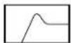
Description: This filter combines the functions of the parametric equalization filter to boost or cut a relatively narrow frequency band with a high-pass filter to roll of the frequencies below the center frequency.** It is commonly used to create a B6 (6th-order Butterworth) response in a vented loudspeaker enclosure.
Passband Gain: Sets the amount of boost or cut for the filter. Control range is +24 dB to -24 dB in 12 -dB steps.
Frequency: Sets the center frequency of the filter. Control range is 20 Hz to 20 kHz in 1-Hz increments.
Octave Bandwidth: Sets the width and slope, or "Q" of the filter (see Figure 4.1). The lower the Q, the wider the filter and the better the transient response and visa versa. Control range is from 0.0416 ( ^1/24 octave) to 6.667 ( 6^2/3 octave) in 0.0416 ( ^1/_24 -octave) increments.
CAUTION: Avoid excessive Qs.*
Low-Pass Shelving Equalization Filter

Description: This filter boosts or cuts low frequencies by the specified amount of gain. When used to cut rather than boost, the filter acts like a high-pass filter rather than a low-pass filter. It has a fixed 1st-order slope (6 dB/octave).
Passband Gain: Sets the amount of boost or cut for the filter. Control range is +24 dB to -24 dB in 12 -dB steps.
Frequency: Sets the -3-dB corner frequency relative to the boosted pass band. Control range is 20 Hz to 20 kHz in 1-Hz increments.
High-Pass Shelving Equalization Filter

Description: This filter boosts or cuts high frequencies by the specified amount of gain. When used to cut rather than boost, the filter acts like a low-pass rather than a high-pass filter. It has a fixed 1st-order slope (6 dB/octave). It is commonly used to compensate for the natural high-frequency roll-off of constant directivity horns.
Passband Gain: Sets the amount of boost or cut for the filter. Control range is +24 dB to -24 dB in 12 -dB steps.
Frequency: Sets the +3-dB corner frequency relative to the boosted pass band. Control range is 20 Hz to 20 kHz in 1-Hz increments.
All-Pass Filter
Description: This filter lets the user perform phase equalization without affecting the frequency response.
4.3.2 Input Processing Delay
A delay can be added to any of the eight input channels in order to time-equalize the various input signals. Delay is displayed in IQ for Windows software in time, feet, and meters. Control range is from 0 to 100 milliseconds in 20-microsecond steps.
4.3.3 Input Gate
The Input Gate feature allows signals above a certain level to pass and attenuates lower level signals. When "open," the Input Gate passes the input signal unattenuated. When "closed," it attenuates the input signal by an amount specified with the Depth control. There are eight parameters which control this feature:
- On/Off: turns this feature on or off.
- Depth: Depth the "closed" gain of the Gate. Control range is from -100 dB to 0 dB in ^1/2 -dB steps.
- Threshold: threshold the peak signal level (after side-chain processing) above which the gate will open. Control range is from -80 to +20 dB in 1/2 -dB steps.
- Hysteresis: sets a range in dB above and below the Threshold which separates the levels at which the Input Gate opens and closes (Figure 4.2). The input signal must reach a level above the Threshold plus Hysteresis to open. Once opened, the input signal must reach a level below the Threshold minus Hysteresis to close. Control range is from 0 dB to 12 dB in 12 -dB steps.

Figure 4.2 Hysteresis
- Delay: each of the A/B Processing Sections have an additional delay function. Since the Input Gate sense is before the delay, a delay at this point allows the gate to act before the signal actually arrives. This gives the gate the opportunity to react early, allowing initial syllables in speech to not be missed by gate reaction time. Delay is displayed in IQ for Windows software in time, feet, and meters. Control range is from 0 to 10 milliseconds in 20 microsecond steps.
- Attack Time: sets the time required for the Input Gate to increase its gain by 20 dB. Control range is from 0.2 milliseconds to 100 milliseconds in 0.01-millisecond steps.
- Hold Time: determines how long the Input Gate will remain open after the control key signal falls below the Threshold. Control range is from .01 seconds to 10 seconds in 0.01-second steps.
- Release Time: sets the time required for the Input Gate to decrease its gain by 20 dB. Control range is from .01 seconds to 10 seconds in 0.01-second steps.
NOTE: NOTES being used with the Duck Priority function must have their individual Gates set up. If the Gates are not set up and turned on, Duck Priority will not work.
4.3.4 Auto-Level
The Auto-Level works in tandem with the Input Gate to compensate for long-term average input levels that vary over time. When the Auto-Level is enabled, the open-state gain of the corresponding Input Gate, normally 0-dB, is adjusted dynamically to achieve a desired average output level. The Auto-Level's affect on input gain is metered by the Input Dynamic Cut/Boost Meter (See section 4.2.2). Eight parameters control this feature:
- On/Off: turns this feature on or off.
- Threshold: sets the input level below which the Auto-Leveler action will be inhibited. This allows the Auto-Leveler to suspend gain changes during quiet passages and, along with Max Gain, prevent excessive system gain. Control range is from -80 to +20 in 1/2 -dB steps.
- Target Level: sets the desired average output level. The Auto-Leveler will expand input signals below this level and compress input signals above this level. Control range is from -100 to +20 in ^1/2 -dB steps.
- Max Gain: sets the maximum gain through the Auto-Leveler. This feature can prevent "run-
away" from occurring during periods of very low signal level. Control range is from -100 to +20 in 1/2 -dB steps.
- Attack Time: sets the time required for the Auto-Level to expand its gain by 20dB. Control range is 0.1 seconds to 60 seconds in 0.1-second steps.
- Release Time: sets the time required for the Auto-Level to compress its gain by 20-dB. Control range is 0.1 seconds to 60 seconds in 0.1-second steps.
- Mode: When set to "Open to Last Gain" the Gate opens to the last gain computed by the Auto-Leveler. In "Open to Idle Gain" position, the Gate opens to a potentially safer "Idle Gain" setting. Using the "Idle Gain" setting can provide a smoother transition from "very soft" to "very loud" input program.
- Idle Gain: sets the initial Gate gain when the Auto-Leveler mode is set to "Open to Idle Gain". Control range is from -100 to +20 in 1/2 -dB steps.
4.3.5 Input Compressor
The input compressor provides a means for controlling the dynamic range of input signals. It is a feed-forward type, which performs the compression after the Input Level Meter. The Input Compressor's affect on input gain is metered by the Input Dynamic Cut/Boost Meter (See Section 4.2.2). Seven parameters control this feature:
- On/Off: turns this feature on or off.
- Compression Ratio: determines how many dB the input level must change for a 1-dB change in output level. Dynamic variations in the input signal will be reduced by a factor equal to the compression ratio. Control range is 2:1 to 32:1.
- Threshold: specifies the average signal level (after side-chain processing) above which the compressor will begin to reduce gain. Control range is from -80 to +20 in 1-dB steps.
- Attack Time: sets the time required for the Compressor to decrease its gain by 20 dB. Control range is from 1.0 milliseconds to 100 milliseconds in 1-millisecond increments.
- Release Time: sets the time required for the Compressor to increase its gain by 20 dB. Control range is from 0.1 to 10 seconds in 10 millisecond increments.
- Soft Knee Width: sets a range in dB around the actual threshold through which the compressor gain is gradually modified from unity to the final compressed gain. Control range is from 0 dB to +20 dB in 1/2 -dB steps.
4.3.6 Automixing
Automatic mixers allow "hands-free" mixing that minimizes many of the undesirable effects of using multiple microphones. Applications such as conference rooms, training rooms and boardrooms typically implement many microphones for individual speakers. Simultaneously mixing all microphones with acceptable gain before feedback many times is not possible. The IQ-USM 810 implements three auto-mixing functions to address this situation: Priority Ducking, NOM Attenuation and Adaptive Gating.
Each of the sixteen A/B Processing Sections can be grouped into one of four Auto-Mix Groups. This allows up to four separate Auto Mixers (A, B, C, D) to be implemented within the same chassis. In addition to the Group assignment, each A/B section includes a separate Enable control. This controls whether the respective channel participates in the assigned group AutoMixing functions. Automixing's affect on input gain is metered by the Input Dynamic Cut/Boost Meter (See section 4.2.2).
Priority Ducking enforces a "priority order" of open microphones such that high-priority inputs "duck" (attenuate) lower-priority inputs. Additionally, a maximum number of equal-priority open microphones may be specified. Keeping the number of open microphones to a minimum reduces background noise while allowing a higher gain before feedback for improved intelligibility. Gates must be ON to use Priority Ducking.Gates Note the six controls and two firmware indicators:
- Master Priority Ducking Enable: turns ducking priority on and off within an automix group.
- Duck Priority Level: assigns a relative priority to each channel. Control range is 1 to 8 where 1 is the highest priority and 8 is the lowest priority.
- Depth: sets the "ducked" mic gain. Control range is from -100 to 0 in 1/2 -dB steps.
- Attack Time: sets the time required for Priority Ducking to attenuate the mic gain by 20-dB. Control range is from 10-milliseconds to 10-seconds in 10-millisecond steps.
-
Release Time: sets the time required for Priority Ducking to increase the mic gain by 20-dB. Control range is from 10-milliseconds to 10-seconds in 10 millisecond steps.
-
Max Number of Open Mics: sets the max number of open mics within the automix group. A last-in, first-out algorithm is used to determine which mics are ducked. When Max Number of Open Mics is equal to one.
- Highest Open Mic Priority Indicator: shows the highest priority level for all open mics within the automix group.
- Total Number of Open Mics Indicator: indicates the total number of presently open mics within the automix group.
NOM attenuation reduces overall system gain as the number of open mics increases beyond one for improved gain before feedback. There are three controls for this feature:
- Master NOM Attenuation Enable: turns NOM Attenuation on and off within an automix group.
- NOM (Number of Open Mics) Attenuation Mode: sets the attenuation algorithm to linear or logarithmic. In linear mode, each open mic beyond one will cause all inputs in the auto-mix group to be attenuated by an amount equal to the Attenuation Step Size, defined below. In logarithmic mode the attenuation per open mic will decrease as more mics open. Linear mode may allow each individual mic to use a higher nominal gain by more aggressively attenuating as more mics open. Logarithmic mode with Attenuation Step Size of 3-dB emulates "classic" NOM attenuation schemes.
- Attenuation Step Size: with NOM Attenuation mode, determines the attenuation as a function of the number of open mics in the auto-mix group. In cases must be ON to use Priority Ducking linear mode, each open mic beyond one increases the attenuation by this amount. Control range is from 0.5 to 3-dB in 1/2 -dB steps.
Adaptive Gating dynamically modifies the gate thresholds in the auto-mix group as a function of the ambient level in the room. The ambient level is computed as the weighted average of the closed mic input levels. The weighted average makes it possible to compensate for mic locations with different ambient levels. There are four controls and one meter for this feature:
- Master Adaptive Gating Enable: turns Adaptive Gating on and off within an automix group.
- Ambient Weighting: the weighting factor used in the ambient level calculation. This control should be set to 1 with the following two exceptions: to exclude the mic from the ambient level
calculation, set the weighting factor to zero; to compensate for a mic in a relatively noisy location set the weighting factor to a value between zero and one. Control range is from 0 to 1 in 0.1-step increments.
- Gate Threshold Ambient Offset: sets the amount above the calculated ambient level for the gate threshold. For inputs with ambient weighting factors equal to zero or one, the actual gate threshold will be offset from the calculated ambient level by this amount. For inputs with ambient weighting factors between zero and one, the offset is expanded prior to adding it to the calculated ambient level – the smaller the weighting factor, the larger the expansion. Control range is from 0 to 20-dB in 1/2 -dB steps.
- Ambient Level Meter: indicates the calculated ambient level.
4.3.7 A/B Processing Section Filters
The signal from all A/B Processing Sections can be filtered with any combination of up to seven different filter types. See Section 4.3.1 for filter descriptions.
4.3.8 Input Signal Muter/Inverter
the signal from all A/B Processing Sections can be independently muted and/or inverted. The Mute function typically provides -100 dB of attenuation.
4.4 Matrix Mixer
The IQ-USM 810 is an 8x10 mixer with unique dual input processing paths (See Figure 5.2). Each of the balanced inputs are split into two separate "A/B" processing sections for a total of sixteen input signal processing paths.
The matrix mixer outputs are routed to the two Main outputs and eight Aux outputs. The signal from either processing section A or B of each input may be routed to any output. For example, the signals from processing sections 1A, 2A, 3B and 4B might be mixed together on AUX 1 output, but the signals from processing sections 1A and 1B could not be mixed together on the same output.
The A/B Processing Sections make it possible to process each input two different ways. For example, if an input were to be routed to a PA system and also recorded, it might be desirable to use the signal from processing section A for the PA system and the signal from processing section B for recording. Figure 4.3 provides a simplified example of signal flow from input to output of one channel.
Note: The following features are controlled and monitored via IQ for Windows software. Refer to Figure 5.2, IQ-USM 810 Signal Flow Block Diagram for feature locations in the audio signal chain.
4.4.1 Input Solo
A control for each A/B Processing Section that allows the signal to be monitored independently by muting all other inputs when the control is activated. A control is also provided to un-mute all inputs.
4.4.2 Main A/B Mix Bus Faders
Controls the signal level from each A/B Processing Section before the Main Mix Busses. Control range is from -100 to +20.
4.4.3 AUX Mix Bus Input Selectors
Selects Processing Section A or B signal to be mixed into each AUX output.

flowchart
graph LR
    A["Input"] --> B["Input Processing"]
    B --> C["Processing Section A"]
    B --> D["Processing Section B"]
    C --> E["Summing Busset M-A"]
    D --> F["Summing Busset M-B"]
    E --> G["Fader"]
    F --> H["Fader"]
    G --> I["Output Processing"]
    H --> J["Output"]
Figure 4.3 Signal Flow Through Matrix Mixer, one channel
4.4.4 AUX Mix Bus Faders
Controls the signal level from each input mixed into each AUX Mix Bus. Control range is from -100 to +20.
4.5 Output Signal Processing
Note: The following features are controlled and monitored via IQ for Windows software. Refer to Figure 5.2, IQ-USM 810 Signal Flow Block Diagram for feature locations in the audio signal chain.
4.5.1 Output Delay
Signal delay can be set for each output channel. The IQ-USM 810 has an inherent 2.85-millisecond delay due to the time required to process the audio. This delay is fixed and is the same for all channels, regardless of the processing used. Delay is displayed in IQ for Windows software in time, feet, and meters. Control range is from 2.85 milliseconds to 2 seconds in 20-microsecond steps.
4.5.2 Output Filters
The signal of each output channel can be filtered with any combination of up to eight different filter types. See Section 4.3.1 for filter parameters.
4.5.3 Ambient-Level
The Ambient-Leveler expands the output channel gain to compensate for a sensed ambient level. The ambient level can be sensed from any of the eight input channels, or the computed ambient level from one of the four auto-mix groups. This feature allows the IQ-USM 810 to maintain optimum signal to noise and intelligibility in environments with varying background noise. Six parameters control this feature:
- On/Off: turns this feature on or off.
- Sense Input: determines the source for the ambient level.
- Sense Threshold: sets a level for the ambient sensor input threshold. The Ambient-Leveler expansion will be inhibited for input levels below this threshold. This action allows the Ambient-Leveler to suspend gain changes when the ambient level is low and, along with Max Added Gain, prevent excessive system gain. Control range is from -80 dB to +20 dB in 1/2 -dB steps.
- Expansion Ratio: determines how much the gain of the output channel will increase for every increase in the ambient signal level above the Threshold setting. A 4:1 Expansion Ratio setting will raise the output gain 4 dB for every 1 dB that
the ambient signal increases. Control range is from 0.1:1 to 5:1.
- Max Added Gain: sets the maximum increase in gain through the Ambient-Leveler. Control range is from 0 dB to +20 dB in 1/2 -dB steps.
- Attack Time: sets the time required for the Auto-Leveler to expand its gain by 20-dB. Control range is from 0.1 seconds to 60 seconds in 0.1-second steps.
- Release Time: sets the time required for the Auto-Level to compress its gain by 20-dB. Control range is from 0.1 seconds to 60 seconds in 0.1-second steps.
- Program Level Dependent Mode: allows the Ambient-Leveler expansion to be inhibited when the actual output Program level is above a prescribed level. This mode prevents program material "feed-through" from artificially increasing the apparent ambient level.
- Program Level Threshold: sets the output program level threshold above which Ambient-Leveling will be inhibited when in “Program Level Dependent” mode. Control range is from -80 to +20 in 1/2 -dB steps.
- Sense Delay: sets the delay after the output program level falls below the Program Level Threshold before the Ambient Leveling begins. Control range is 0 to 60 seconds in 0.1-second increments.
4.5.4 Main Output Faders
Controls the signal level from main outputs A and B after the Output Processing Section. Control range is from -100 to +20.
4.5.5 AUX Output Faders
Controls the signal level from each AUX output after the Output Processing Section. Control range is from -100 to +20.
4.5.6 Output Limiter
The Output Limiter function provides a means of directly monitoring and controlling peak output level. It is especially valuable for the protection of amplifiers, loudspeakers and other audio equipment. The Output Limiter operates similar to a compressor with an infinite compression ratio, preventing the output level from exceeding the specified Threshold. Four parameters control this feature:
- On/Off: turns this feature on or off.
- Threshold: used to set the peak signal level above which compression occurs. Control range is from -80 to +20 in 1/2 -dB steps.
- Attack Time: sets the time required for the Limiter to decrease its gain by 20-dB. Control range is from 1 milliseconds to 100 milliseconds in 1-millisecond steps.
- Release Time: determines how long it takes for the gain to return to normal when the level drops below the Threshold. Control range is from 10 milliseconds to 10 seconds in 10-millisecond steps.
4.5.7 Output Muter/Inverter
The output signal of each main and AUX output channel can be independently muted and/or inverted. The mute function typically provides -100 dB of attenuation.
4.6 Multi-Function Control Port
Note: The following feature parameters are set up via IQ for Windows software. Refer to Section 6.2 for information on using the Multi-Function Control Port.
The Multi-Function Control Port provides a means for external monitoring and control of "objects" within the IQ-USM 810.* The Multi-Function Control Port implements sixteen outputs and sixteen inputs along with power supply outputs and common grounds. All sixteen (1-16) outputs are digital "logic outs." Eight of the inputs (AIN1-8) are capable of monitoring digital and analog external signals. The other eight inputs (DIN1-8) are digital only. Section 6.2 gives pin assignments, electrical specifications and application examples for the Multi-Function Control Port.
4.6.1 Logic Digital Inputs (DIN1-8)
These inputs are digital (high or low) only. They can be used to control one or more objects within the IQ-USM 810. (See section 5 for hardware specifications). There is one indicator and six controls for each input:
- Pin State Indicator: indicates the "Pin-High" or "Pin-Low" status of the actual hardware input.
- Mode: controls the mode of the input pin.
Following are descriptions of the available modes:
Set Object(s): allows a single input to control up to fifty objects within the IQ-USM 810. Binary objects can be controlled with normal or inverted logic. Multi-valued objects (e.g. gains, thresholds, etc.) can be set to different settings for input transitions from low-to-high and high-to-low.
Bump Object(s): similar to Set Object mode except that rather than setting the object to an absolute value, the specified values are added to the current object values. Upper and lower limits can be set to limit the range of the control.
Bump Object(s) Continuously: similar to Bump Object mode, except that the specified values are added to the object value continuously at 14 second intervals.
Recall Preset: enables the input to recall one of the 32 user presets. Separate presets can be recalled for low-to-high and high-to-low transitions.
Room Combine: enables the input (1-8 only) to be used in a binary combination of digital inputs to recall one of the 32 user presets. Inputs (9-16) cannot be used in this mode. Using all inputs (1-8) allows up to 256 unique combinations. Lesser numbers of inputs can be used for fewer combinations. This mode can be used for room-combining applications where switch-closures indicate moving room dividers.
4.6.2 Analog Inputs (AIN 1-8)
These inputs can be used as analog or digital inputs to control one or more objects within the IQ-USM 810. (See section 5 for hardware specifications) There is one indicator and six controls for each input:
- Pin State Indicator: indicates the logical "Pin-High" or "Pin-Low" status of the actual hardware input.
- Mode: controls the mode of the input pin.
Following are descriptions of the available modes:
Set Object(s): allows a single input to control up to fifty objects within the IQ-USM 810. Binary objects can be controlled with normal or inverted logic. Multi-valued objects (e.g. gains, thresholds, etc.) can be set to different settings for input transitions from low-to-high and high-to-low.
Bump Object(s): similar to Set Object mode except that rather than setting the object to an absolute value, the specified values are added to the current object values. Upper and lower limits can be set to limit the range of the control.
Bump Object(s) Continuously: similar to Bump Object mode, except that the specified values are added to the object value continuously at 14 second intervals.
Recall Preset: enables the input to recall one of the 32 user presets. Separate presets can be recalled for off-to-on and on-to-off transitions.
Vary Object(s) Continuously: allows an analog input voltage to control up to fifty objects within the IQ-USM 810. Each object can be varied over a user-specified range. This mode is typically used for external gain controls.
4.6.3 Digital Outputs
There are sixteen digital outputs. Each output may be controlled manually, configured to indicate the state of a binary object or configured to indicate whether a particular preset is loaded. There is one indicator and six controls for each output:
- Pin State Indicator: indicates the logical "Pin-High" or "Pin-Low" status of the actual hardware output.
- Manual: directly controls the output state of the corresponding pin when in Manual mode.
- Polarity: changes the polarity of the digital output regardless of the pin control mode.
- Mode: controls the mode of the output pin. The available modes are:
- Reflect: causes the output to directly reflect the state of its Manual control
- Reflect Parameter: causes the output to reflect the state of the selected binary object within the IQ-USM 810. Only a single object may be specified.
- Reflect Preset: causes the output to reflect whether the chosen preset number is loaded within the IQ-USM 810.
5 Technical Information
5.1 Technical Description
Following is a technical description of the operation of the IQ-USM 810. Refer to the block diagrams on the following pages for illustration of signal flow.
5.1.1 Audio
Input Section: Each audio input signal first passes through a balanced filter designed to eliminate RF interference. The RF filters are a balanced network of chokes, ferrite beads, and capacitors that attenuate both common-mode and differential-mode signals above 500 kHz. Optional input isolation transformers are available.
The balanced signal then enters the input switching circuit. This circuit can insert a 25-dB pad for line level signals or apply phantom power to the input terminals (24VDC through two 2 Kohm resistors). The signal is filtered again to eliminate lower-frequency RF energy such as interference from the AM broadcast band.
A discrete preamp stage takes the balanced input signal and provides 13 to 45 dB of voltage gain adjustable by a rear panel potentiometer. The preamp output provides a single-ended voltage output that is then coupled to a single-ended-to-differential amplifier that also provides the bias offset needed by the A/D converter.
A 24-bit high-resolution A/D converter samples the input audio at 48 kHz. The audio processing is set to provide +20 dBu as full scale, allowing full utilization of the dynamic range of the converter. Each converter supplies a two-channel digital audio stream to the DSPs for processing. One A/D converter acts as a master to supply sampling clocks to the rest of the system. A 12.288 MHz oscillator (256 times the 48 kHz sampling rate) acts as the master clock source.
DSP Processing Section: Four DSP processors supply all of the digital audio processing in the unit. Serial digital audio from the input converters are sent to the DSP board for processing. The input audio is routed to the two input DSPs. The processors collect 16 samples of audio, then process the audio as a "brick" of data. After the input DSPs have processed the data, they transfer the audio bricks to shared memory. The two output DSPs then retrieve the audio from memory and do the required output processing. The audio is then sent serially from the DSPs serial ports to the Output board.
The DSP processors have a 30 MHz clock, while serial digital audio is locked to serial clock (3 MHz) and frame sync clock (48 KHz) supplied from the Input board.
An interface to the System Controller board allows programming of the DSPs, control updates, and metering information to be passed to the outside world. The DSPs depend upon the System Controller for programming upon reset or initial power, as there is no nonvolatile memory on board.
Output Section: Output serial digital audio from the DSP board is sent to the output board for conversion and analog processing. The serial digital audio is comprised of two channels of 24-bit signals. Each DAC converts the audio data stream into two differential output channels. A differential amplifier filters the DAC's audio output and provides single-ended audio to a gain stage that sets the full-scale output of the DAC. A single-ended-to-differential stage provides a 50-ohm output. Optional transformers are available for the Main Outputs.
5.1.2 Control and Interface
System Controller: The System Controller board provides interface to the outside world as well as providing all of the program storage and initialization. At reset, the control processor uses boot code from nonvolatile flash memory. Program code is then transferred to fast RAM and the processor begins to run. Each DSP processor is then booted via the system interface and upon successful booting of all the DSPs, audio processing begins.
- Flash Memory Storage: In addition to storing program code for the control and DSP processors, flash memory provides storage for all non-volatile data including presets and settings.
- IQ Loop: The dual RJ-45 connector allows IN/OUT connection to an IQ loop. The IQ-USM 810 can act as either an ordinary component or an interface. When acting as an interface, a computer needs to be connected to the RS232 interface.
- RS232: When the IQ-USM 810 is in interface mode, the computer communicates with the IQ-USM 810 and all components on its IQ loop via this port. Front Panel control allows setting of the baud rate, and IQ for Windows software automatically adjusts to this setting. When in the component mode, the IQ-USM 810 can still communicate with the computer through this port.
- DSP Interface: The control processor boots all of the DSP processors via this interface. Additionally, the control processor sets all audio processing controls and receives all meter data over this port.
- Control Port: External events can be either generated or monitored via this port and used to control or signal some function within the unit. Sixteen digital outputs, eight digital inputs, and eight analog inputs provide access to the unit. current-limited voltages (+5V and +10V) are provided to power external circuits.
Digital Outputs: These sixteen outputs provide +10V at 10 mA as configured by IQ software. These outputs can signal either a specific event or can signal the gate status of the input channels.
Digital Inputs: Eight switched inputs can be linked to specific functions, such as muters, in the unit. These inputs can also be used to select a particular preset based upon a desired switch combination on these inputs. The inputs are current driven and will accept any DC voltage to +25VDC.
Analog Inputs: Any fader in the unit can be controlled via one of these inputs. A 10VDC swing allows the control to vary from null to full scale. IQ software controls provide limiting of the fader value in the unit.
- Real Time Clock: An internal real time clock allows presets to be called based upon a real time. The event scheduler works independently of the computer and can recall a specific preset either as a one-time function or a repeatable event with a specific start time and repeat rate. The clock is capable of retaining the correct time for up to 45 days without power applied the IQ-USM 810.
- Front Display: The control processor communicates to the front display via a serial interface. All LED updates and display information is passed to the front panel in this manner. The front-panel switches are monitored by the control processor.
- Power Interface: The System Controller board receives voltages from the power supply and routes them to the Input and DSP boards. A regulator creates the +10V available for the Control Port.

flowchart
graph TD
    A["Power Supply"] --> B["100VAC - 240VAC 50/60 Hz"]
    B --> C["System Control"]
    C --> D["Front Display"]
    C --> E["DSP"]
    E --> F["Input"]
    E --> G["Output"]
    F --> H["Audio input (8)"]
    G --> I["Audio Output (10)"]
    C --> J["Control Port"]
    C --> K["RS232"]
    C --> L["Crown Bus"]
Figure 5.1 IQ-USM 810 Circuit Block Diagram
5.2 Specifications
General
Front Panel Controls: Front-panel switches select IQ Address, Baud Rate, and any of 32 user-defined presets (P01–P32).
Rear-Panel Controls: A 3-position selector switch (mic/line/phantom) and a calibrated gain control for each input.
Connectors: IQ Bus: RJ-45 for input/output, RJ-45 for daisy output, RS232: DB9F computer interface for both component and interface modes. Multi-function Port: DB37M for analog inputs, digital inputs, digital outputs, +5VDC, +10VDC and Ground. Audio Inputs and Outputs: 3-pin male removable barrier block connectors, Buchanan® type cable connector or equivalent supplied. AC Power: IEC320 connector for AC power cord.
Display: A blue front-panel Enable indicator lights to show that the unit is plugged in and AC power is being supplied. An amber front-panel Data Signal Presence Indicator (DATA) flashes whenever commands addressed to the IQ-USM 810 are received. A green front-panel Interface indicator lights when the IQ-USM 810 is being used as system interface. A three-segment digital display indicates the IQ-USM 810's initialization sequence by displaying each processor's name as it comes online, indicates the presently selected preset, indicates the IQ address and baud rate while those parameters are being adjusted, indicates when a parameter has been stored in flash memory, and when any parameter is varied from its value within the currently selected preset. Ladder Display: A front panel, sixteen-segment LED display matrix can be set to three different operating modes: Level Meter, Gate Status, and Infinity Pattern.
Power Requirements: 100VAC to 240VAC, 35VA nominal.
Protection: if communication is lost, the unit will continue to function with the last commands received.
RS232 Data Communication
Baud Rate: Selectable to 19.2 K, 38.4 K, 57.6 K, or 115.2 K BAUD.
Data Format: Serial, binary, asynchronous; 1 start bit; 1 stop bit; 8 data bits; no parity.
IQ Bus Data Communication
Data Rate: 38.4 K BAUD.
Data Format: Serial, binary, asynchronous; 1 start bit; 1 stop bit; 8 data bits; no parity.
IQ Bus Interface Type: Optically isolated 20 mA current loop.
Operation: Half-duplex.
Transmission Distance: Variable from 200 to 3000 feet (61 to 914 meters), depending upon wire capacitance. Typically 1000 feet (305 meters) using shielded twisted-pair wire, #26 AWG or larger. Can be extended with an IQ Repeater.
Audio
Phantom Voltage: +24VDC at 10 mA.
Input Gain Range: +20 dB to -12 dB.
Digital Sampling: 24 bit, 48 kHz.
Input Impedance: 20 kohms balanced, 10 kohms unbalanced.
Dynamic Range: Greater than 100 dB (A-weighted, 20 Hz–20 KHz).
Frequency Response: ± 0.5 dB, 20 Hz–20 kHz.
Common Mode Rejection: 50 dB (typical).
Crosstalk: Greater than 80 dB at 10 kHz.
Total Harmonic Distortion: Less than 0.05% THD + N (1 kHz, 0 dBu).
Output Impedance: 100 ohms balanced, 50 ohms unbalanced.
Max Input Level: +32 dBu (line) or +7 dBu (mic).
Max Output Level: +20 dBu.
Control Port
Power Supply: +5VDC and +10VDC outputs are provided. The total output current is limited to 1A.
OutputsOutputs
Logic Low: less than 0.1V
Logic High: 10V (via internal pull-up)
Output Current is limited to 10ma max per pin. InputsInputs
Input Impedance: greater than 50kohm
Logic Low: less than 0.5V
Logic High: greater than 5V
Analog Range: 0 to 10V (for inputs 9-16 only)
Max Input Voltage: 25V
Mechanical
Weight: 13 pounds, 4 ounces (6.1 kg).
Dimensions: 19-inch (483-cm) standard rack mount width (EIA RS-310-B), 16-inch (40.6-cm) depth behind mounting surface, and 3.5-inches (8.9-cm) height.

flowchart
graph TD
    subgraph_Section_A["Processing Section A"]
        A1["1 MLP"] --> A2["Filter Group"]
        A2 --> A3["Delay"]
        A3 --> A4["Delay"]
        A4 --> A5["Static Gate"]
        A5 --> A6["Auto/Leveler"]
        A6 --> A7["Compressor"]
        A7 --> A8["Automix"]
        A8 --> A9["Filter Group"]
        A9 --> A10["Muter/Inverter"]
    end
    subgraph_Section_B["Processing Section B"]
        B1["2 MLP"] --> B2["Filter Group"]
        B2 --> B3["Delay"]
        B3 --> B4["Delay"]
        B4 --> B5["Static Gate"]
        B5 --> B6["Auto/Leveler"]
        B6 --> B7["Compressor"]
        B7 --> B8["Automix"]
        B8 --> B9["Filter Group"]
        B9 --> B10["Muter/Inverter"]
    end
    subgraph_Section_C["Processing Section C"]
        C1["3 MLP"] --> C2["Filter Group"]
        C2 --> C3["Delay"]
        C3 --> C4["Delay"]
        C4 --> C5["Static Gate"]
        C5 --> C6["Auto/Leveler"]
        C6 --> C7["Compressor"]
        C7 --> C8["Automix"]
        C8 --> C9["Filter Group"]
        C9 --> C10["Muter/Inverter"]
    end
    subgraph_Section_D["Processing Section D"]
        D1["4 MLP"] --> D2["Filter Group"]
        D2 --> D3["Delay"]
        D3 --> D4["Delay"]
        D4 --> D5["Static Gate"]
        D5 --> D6["Auto/Leveler"]
        D6 --> D7["Compressor"]
        D7 --> D8["Automix"]
        D8 --> D9["Filter Group"]
        D9 --> D10["Muter/Inverter"]
    end
    subgraph_Section_E["Processing Section E"]
        E1["5 MLP"] --> E2["Filter Group"]
        E2 --> E3["Delay"]
        E3 --> E4["Delay"]
        E4 --> E5["Static Gate"]
        E5 --> E6["Auto/Leveler"]
        E6 --> E7["Compressor"]
        E7 --> E8["Automix"]
        E8 --> E9["Filter Group"]
        E9 --> E10["Muter/Inverter"]
    end
    subgraph_Section_F["Processing Section F"]
        F1["6 MLP"] --> F2["Filter Group"]
        F2 --> F3["Delay"]
        F3 --> F4["Delay"]
        F4 --> F5["Static Gate"]
        F5 --> F6["Auto/Leveler"]
        F6 --> F7["Compressor"]
        F7 --> F8["Automix"]
        F8 --> F9["Filter Group"]
        F9 --> F10["Muter/Inverter"]
    end
    subgraph_Section_G["Processing Section G"]
        G1["7 MLP"] --> G2["Filter Group"]
        G2 --> G3["Delay"]
        G3 --> G4["Delay"]
        G4 --> G5["Static Gate"]
        G5 --> G6["Auto/Leveler"]
        G6 --> G7["Compressor"]
        G7 --> G8["Automix"]
        G8 --> G9["Filter Group"]
        G9 --> G10["Muter/Inverter"]
    end
    subgraph_Section_H["Processing Section H"]
        H1["8 MLP"] --> H2["Filter Group"]
        H2 --> H3["Delay"]
        H3 --> H4["Delay"]
        H4 --> H5["Static Gate"]
        H5 --> H6["Auto/Leveler"]
        H6 --> H7["Compressor"]
        H7 --> H8["Automix"]
        H8 --> H9["Filter Group"]
        H9 --> H10["Muter/Inverter"]
    end
Figure 5.2 IQ-USM 810 Signal Flow Block Diagram
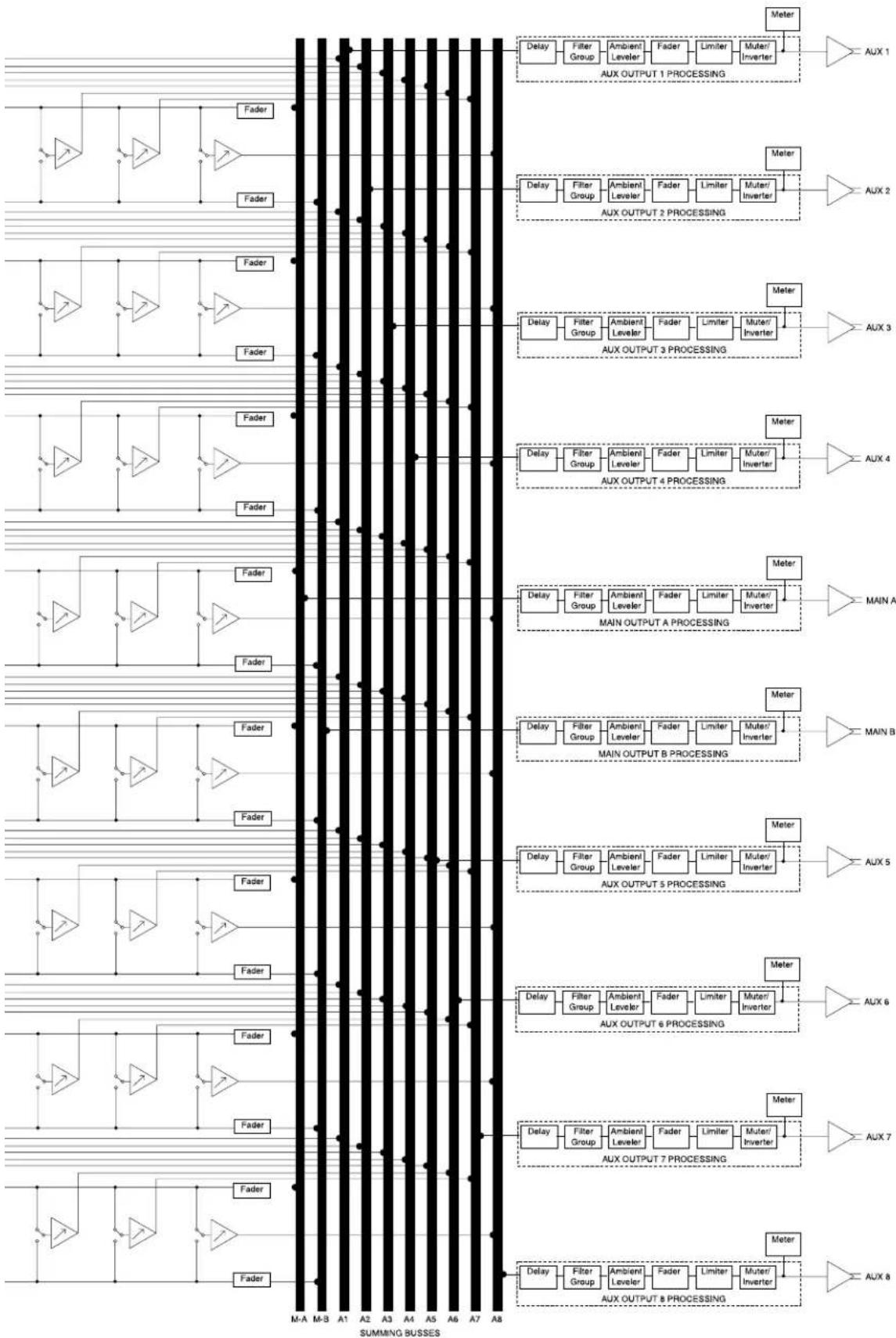
flowchart
graph TD
    subgraph AUX_1
        AUX1 --> Delay1["Delay"]
        AUX1 --> FilterGroup["Filter Group"]
        AUX1 --> AmbientLeveler["Ambient Leveler"]
        AUX1 --> Fader1["Fader"]
        AUX1 --> Limiter1["Limiter"]
        AUX1 --> MuterInverter["Muter/ Inverter"]
        AUX2 --> Delay2["Delay"]
        AUX2 --> FilterGroup["Filter Group"]
        AUX2 --> AmbientLeveler["Ambient Leveler"]
        AUX2 --> Fader2["Fader"]
        AUX2 --> Limiter2["Limiter"]
        AUX2 --> MuterInverter["Muter/ Inverter"]
        AUX3 --> Delay3["Delay"]
        AUX3 --> FilterGroup["Filter Group"]
        AUX3 --> AmbientLeveler["Ambient Leveler"]
        AUX3 --> Fader3["Fader"]
        AUX3 --> Limiter3["Limiter"]
        AUX3 --> MuterInverter["Muter/ Inverter"]
        AUX4 --> Delay4["Delay"]
        AUX4 --> FilterGroup["Filter Group"]
        AUX4 --> AmbientLeveler["Ambient Leveler"]
        AUX4 --> Fader4["Fader"]
        AUX4 --> Limiter4["Limiter"]
        AUX4 --> MuterInverter["Muter/ Inverter"]
        MAIN_A --> Delay5["Delay"]
        MAIN_A --> FilterGroup["Filter Group"]
        MAIN_A --> AmbientLeveler["Ambient Leveler"]
        MAIN_A --> Fader5["Fader"]
        MAIN_A --> Limiter5["Limiter"]
        MAIN_A --> MuterInverter["Muter/ Inverter"]
        MAIN_B --> Delay6["Delay"]
        MAIN_B --> FilterGroup["Filter Group"]
        MAIN_B --> AmbientLeveler["Ambient Leveler"]
        MAIN_B --> Fader6["Fader"]
        MAIN_B --> Limiter6["Limiter"]
        MAIN_B --> MuterInverter["Muter/ Inverter"]
        AUX_5 --> Delay7["Delay"]
        AUX_5 --> FilterGroup["Filter Group"]
        AUX_5 --> AmbientLeveler["Ambient Leveler"]
        AUX_5 --> Fader7["Fader"]
        AUX_5 --> Limiter7["Limiter"]
        AUX_5 --> MuterInverter["Muter/ Inverter"]
        AUX_6 --> Delay8["Delay"]
        AUX_6 --> FilterGroup["Filter Group"]
        AUX_6 --> AmbientLeveler["Ambient Leveler"]
        AUX_6 --> Fader8["Fader"]
        AUX_6 --> Limiter8["Limiter"]
        AUX_6 --> MuterInverter["Muter/ Inverter"]
        AUX_7 --> Delay9["Delay"]
        AUX_7 --> FilterGroup["Filter Group"]
        AUX_7 --> AmbientLeveler["Ambient Leveler"]
        AUX_7 --> Fader9["Fader"]
        AUX_7 --> Limiter9["Limiter"]
        AUX_7 --> MuterInverter["Muter/ Inverter"]
        AUX_8 --> Delay10["Delay"]
        AUX_8 --> FilterGroup["Filter Group"]
        AUX_8 --> AmbientLeveler["Ambient Leveler"]
        AUX_8 --> Fader10["Fader"]
        AUX_8 --> Limiter10["Limiter"]
        AUX_8 --> MuterInverter["Muter/ Inverter"]
    end
    subgraph SUMMING BUSSES
        SUMMING BUSSES --> M-A
        SUMMING BUSSES --> M-B
        SUMMING BUSSES --> A1
        SUMMING BUSSES --> A2
        SUMMING BUSSES --> A3
        SUMMING BUSSES --> A4
        SUMMING BUSSES --> A5
        SUMMING BUSSES --> A6
        SUMMING BUSSES --> A7
        SUMMING BUSSES --> A8
    end
6 Working With IQ
This section provides additional information about Crown's IQ System with special guides to aid in the installation and use of the IQ-USM 810. For more information about any of these topics, contact the Crown Technical Support Group (see Section 7 for contact information).
6.1 A Closer Look at Audio Signal Wiring
6.1.1 Input
Three-terminal removable barrier block connectors are provided for the audio inputs (see Figure 6.1). Each input has an input selector switch. Slide it to the left (M) for microphone signal levels up to -5 dBu (0 dBu = 0.775 volts). Select the center position (L) for line level signals up to +20 dBu. Slide it to the right (P) to provide 24VDC to mics requiring phantom power.
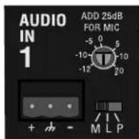
Figure 6.1 An Audio Input Section
Each input has a screwdriver-set, calibrated gain control to compensate for different input source levels. The slot on the control shaft points to the gain setting. The settings are labelled for line-level input. Add 25 dB to the scale if the inputs are switched for microphone level signals.
Use a screwdriver to adjust the gain pot so that the input signal level plus gain equals roughly 0 dBu. You will need to know, or estimate, the level of the input source. Setting the source signal level to approximately 0 dBu will provide 20 dBu of headroom in the input preamp. Some recommended settings are given in Figure 6.2.
Balanced sources should be wired as shown in Figure 6.3. Notice that the shield is not connected to the chassis ground of the source if the source is also connected to the AC ground (that is, it has a grounded AC plug). This prevents unwanted ground loops.

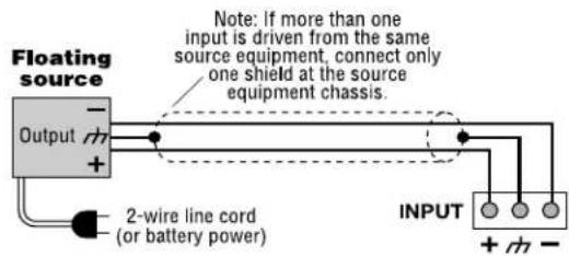

Figure 6.3 Balanced Audio Input Wiring
| Pro Audio equipment | Semi-Pro or consumer equipment | Dynamic mic, speech | Condenser mic, speech | Hot condenser mic, speech | Dynamic mic, music | Hot condenser mic, music | Close-miked dynamic mic, bass/drums | Close-miked dynamic mic, kick drum, guitar amp | |
| dBm/dBV (nominal) | +4 dBm | -10 dBV | -75 dBV | -65 dBV | -45 dBV | -55 dBV | -25 dBV | -15 dBV | -5 dBV |
| dBu (nominal) | +4 dBu | -8 dBu | -73 dBu | -63 dBu | -43 dBu | -53 dBu | -23 dBu | -13 dBu | -3 dBu |
| Suggested Setting | -4 (L) | +8 (L) | +20 (M) | +18 (P) | +11 (P) | +20 (M) | -2 (P) | -12 (M) | -12 (M) or +3 (L) |
0 dBm = 0.775 VRMS with a 600-ohm load, 0 dBV = 1 VRMS, 0 dBu = 0.775 VRMS
Fig. 6.2 Suggested Audio Input Gain Control Settings
Unbalanced sources should be wired as shown in Figure 6.4. The examples in Figure 6.4 are grouped according to whether twin-lead shielded wire or single-conductor coax (or twisted pair) wire is used.


Figure 6.4 Unbalanced Audio Input Wiring
6.1.2 Output
Three-terminal removable barrier block connectors are provided for audio output (Figure 6.5). Both main and AUX Audio Outputs are balanced and can drive 1200 ohms or more to +20 dBu.
The Main Audio Outputs are connected to the main summing busses, and operate in a 8x2 arrangement. They are provided for connection with other audio equipment such as power amplifiers.
The AUX Audio outputs are connected to the AUX summing busses and allow the IQ-USM 810 to operate as a 8x10 matrix. Any input can be routed to any main or AUX Audio Output via the summing buss.
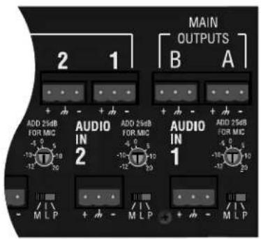
Figure 6.5 Back Panel Output Connectors
Balanced output wiring is shown in Figure 6.6. Notice that if the load is connected to AC ground, the shield should not be connected to the output ground terminal. This will prevent unwanted ground loops.
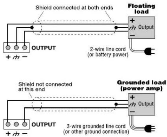
Figure 6.6 Balanced Audio Output Connections
Unbalanced output wiring is shown in Figure 6.7.

Figure 6.7 Unbalanced Audio Output Connections
6.2 Using the Multi-Function Control Port
The IQ System offers tremendous flexibility and the Multi-Function Control Port feature provides an even greater means of tapping into it. It can be used to turn peripherals on and off, send signals to other system components, receive digital and/or analog signals from other components, and indicate status of the input gates.
Pins 1 through 8 and 20 through 27 are assignable to indicate mix channel gate status, (with logic=hi for gate open or audio on), selected preset status, or status of any logical binary control or sensor (most likely gate and preset). Pins 20 through 27 additionally can function as general AUX outputs. A total of 1 amp of current is available from all outputs. Pins 12 through 19 are assignable to logic preset recall and general control for logical type objects within the unit, and are assignable to any combination of mute controls. Pins 30 through 37 function as analog inputs and are assignable to any combination of fader controls. Figure 6.8 shows pin assignments for the Multi-Function Control Port.
6.2.1 Control Port Outputs
When Control Port outputs are turned on, +10VDC at 10 mA is supplied across the output to ground. A total of 1 amp of current is available. Figure 6.8 shows pin assignments.
There are many possible uses for the Control Port outputs. For example, they can be used to turn on auxiliary cooling fans. To do this the output signal might be used to close a relay. The relay would then turn the fans on or off. This is shown in Figure 6.9.
USM 810 Control Port (DB37)
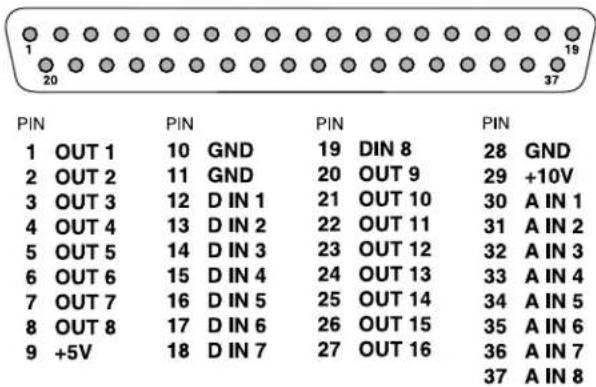
Figure 6.8 Control Port Pin Assignments

Figure 6.9 A Sample Control Port Output Circuit
By monitoring the operating condition of amplifiers with the IQ System software, the need for additional cooling would be apparent. The same software could then be used to turn on the appropriate Control Port input.
Another use for the Control Port outputs might be to light an LED on an annunciator panel to indicate preset status, input channel mute, or any other on/off type function. A sample LED circuit is shown in Figure 6.10.

Figure 6.10 A Sample Control Port Output LED Circuit
6.2.2 Control Port Analog Inputs
The Control Port analog inputs can be used to sense the presence of an analog input signal level. These analog inputs allow the use of ordinary 10 k ohm linear potentiometers for level control. An example of such a circuit is shown in Figure 6.11. Analog inputs can alternately be set to sense simple contact closure.

Figure 6.11 Sample Control Port Analog Input Circuit
6.2.3 Control Port Digital Inputs
The Control Port digital inputs can be used to sense logic high or low signals to control many of the features of the IQ-USM 810. The inputs are current-driven and will accept +5V or +10V inputs, and are well suited for sensing contact closure.
One particularly useful way to use the Logic Input Control Mode is to sense the opening and closing of switches in a room-combining system. Switches are mounted in retractable partitions between rooms. When a partition is opened, the signal at the digital input will be interpreted as a logic "low," and when the partition is closed, the signal at the digital input will be interpreted as a logic "high." When specific mapped combinations of logic low and highs are sensed, the IQ-USM 810 will activate a preset to tailor the audio system to the currently configured space.
Another possible use for the Logic Input Control Mode is to sense switch closures along the path of a ride in a theme park to signal the ride's location, and change to different presets accordingly.
An example of a switch wired to a logic input is shown in Figure 6.12.
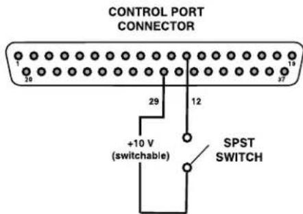
Figure 6.12 Sample Control Port Digital Input Circuit
A screw-terminal board with barrier-block to DB37M connections makes it easy to interface external circuitry to the Multi-Function Control Port.*
6.3 Working with RJ-45 Connectors
Pin numbers for standard RJ-45 connectors are indicated in Figure 6.10.

Figure 6.10 RJ-45 Pin Numbers
When wiring RJ-45 connectors, it is good practice to follow the EIA/TIA 568B protocol for RJ-45 connector cable. This protocol assigns wire colors as follows:
1 white-orange 5 white-blue
2 orange-white 6 green-white
3 white-green 7 white-brown
4 blue-white 8 brown-white
When attaching RJ-45 connectors to cable, be sure to use the appropriate crimping tool and verify that the connector is properly seated into the tool or damage will result.
6.4 A Closer Look at IQ Bus Wiring
The IQ Bus is a serial communication loop designed to transmit IQ commands and data. As implemented in the IQ-USM 810, it is a 20-mA current loop operating at a baud rate of 38.4 K.
The IQ Bus connection can use inexpensive twisted-pair wiring (shielded or unshielded). The IQ Bus loop must be unbroken. If fiber optic cabling is required, contact the Crown Technical Support Group (see page 32 for contact information).
Here are some guidelines for twisted-pair wiring:
- When interference is a problem, use shielded twisted-pair wire at least 26 AWG in size. The wire should be of good quality and should have low capacitance—30 pF/foot or less is suitable.
The shield serves two purposes: First, it helps prevent the IQ data signal from transmitting to nearby audio wiring. Second, it helps prevent outside RF from interfering with the data signal. However, in most cases interference is not a problem and, since unshielded wire has lower capacitance, it is a better choice for typical applications.
- Minimize the total capacitance of a IQ Bus loop. The total combined capacitance for an IQ Bus loop should be less than 30 nF. To calculate this, allow approximately 60 pF for each IQ component in a loop. This accounts for a slight signal degradation which occurs as data signals pass through a component.
- Add an IQ Repeater for very long loops—greater than 1,000 feet (305 m)—or when required by high-capacitance wire. Crown recommends adding a repeater after 50 devices or in the case of loops longer than 1,000 feet, although sometimes is possible to go 2,000 feet (610 m) or more before a repeater is required. The most significant factor in determining maximum loop length is wire capacitance. Lower capacitance will allow longer loops (unsheilded wire usually has lower capacitance).
Outside RF interference is seldom a problem for a IQ Bus loop—especially if shielded twisted-pair wire is used. However, there are extreme situations when fiber optic wiring is recommended. For example, locating a IQ Bus loop next to an AM radio transmission line may require fiber optic cabling. An extremely long IQ Bus loop distance may also require fiber optic cabling.
6.5 The IQ-USM 810 as a 1-Loop IQ Interface
The IQ-USM 810 can serve as an IQ interface between a host computer and a single IQ Bus loop for other IQ components. This can eliminate the need for an external IQ Interface (IQ INTII) in a small system. The IQ-USM 810 connects directly to the host computer via the DB9 serial connector. See Section 3.2 for specific instructions on wiring and address settings.
6.6 IQ Bus Wiring with a Patch Panel.
The IQ Bus can be wired using a patch panel, making addition and removal of IQ components in the field easier and faster with less chance of loosing loop integrity. As in a conventional loop arrangement, the IQ Bus is wired in a serial loop, but all IQ components on the loop are connected at a central patch panel (see Figure 6.11). Typically RJ-45 style patch panels are implemented, and allow the use of off-the-shelf passthrough network cable for connecting the IQ-USM 810 to the patch panel.* The combination IQ Bus Input/Output Connector on the IQ-USM 810 has been designed specifically for this use.
When wiring the IQ Bus with a patch panel, all unused ports must be terminated with shorting plugs to close the loop. For more information about wiring the IQ Bus with a patch panel, contact the Crown Audio Technical Support Group (see Section 7 for contact information).

flowchart
graph TD
    A["IQ-USM 810"] --> B["IQ BUS INPUT / OUTPUT CONNECTOR"]
    B --> C["CAT. 5 PATCH PANEL"]
    C --> D["STANDARD THRU-TYPE NETWORK CABLE (CAT. 5)"]
    D --> E["IQ Component"]
    D --> F["IQ Component"]
    D --> G["Shorting Plug FOR UNUSED PORTS"]
    D --> H["IQ Component"]
    H --> I["DIN IN"]
    H --> J["DIN OUT"]
Figure 6.11 Example of a IQ Bus loop Wired Through a Patch Panel
7 Service
Crown amplifiers are quality units that rarely require servicing. Before returning your unit for servicing, please contact Crown Technical Support to verify the need for servicing.
This unit has very sophisticated circuitry which should only be serviced by a fully trained technician. This is one reason why each unit bears the following label:

CAUTION: To prevent electric shock, do not remove covers. No user serviceable parts inside. Refer servicing to a qualified technician.
7.1 Factory Service
IQ products are serviced only at the Crown Factory.
To obtain factory service, fill out the service information page found in the back of this manual and send it along with your proof of purchase and the defective unit to the Crown factory.
For warranty service, we will pay for ground shipping both ways in the United States. Contact Crown Customer Service to obtain prepaid shipping labels prior to sending the unit. Or, if you prefer, you may prepay the cost of shipping, and Crown will reimburse you. Send copies of the shipping receipts to Crown to receive reimbursement.
Your repaired unit will be returned via UPS ground. Please contact us if other arrangements are required.
7.1.1 Factory Service Shipping Instructions:
-
Before sending a Crown product to the factory for service, first call the Crown Service Department for a return authorization (RA) number. Or go online to http://crownweb.crownintl.com/crownrna/.
-
Be sure to fill out the service information form that follows and enclose it with your shipment, either inside the box or in a packing slip envelope securely attached to the outside of the shipping carton. Do not send the service information form separately. If you are sending the unit from a Shipping Center, we recommend taping the form to the product. We also recommend recording the serial number and model before shipping for your reference.
-
To ensure the safe transportation of your unit to the factory, ship it in an original factory packing container. If you don't have the original carton, you may obtain a product service foam-in-place shipping pack from the Crown Factory Service Department at the number listed below. For non-warranty service, you may also provide your own shipping pack, however we still recommend using a Crown Supplied Shipping Container. Minimum recommended requirements for materials are as follows: 275 P.S.I. burst test Double-Wall carton that allows for 2-inch solid Styrofoam on all six sides of unit or 3 inches of plastic bubble wrap on all six sides of unit; securely seal the package with an adequate carton sealing tape. Do not use light boxes or "peanuts." Damage caused by poor packing cannot be covered under warranty.
-
Do not ship the unit in any kind of cabinet (wood or metal). Ignoring this warning may result in extensive damage to the unit and the cabinet. Accessories are not needed-do not send the product documentation, cables and other hardware.
If you have any questions, please contact Crown Factory Service.
Crown Factory Service
1718 W. Mishawaka Rd., Elkhart, Indiana 46517 U.S.A.
Telephone: 574-294e8200 800-342-6939 (North America, Puerto Rico, and Virgin Islands only)
Facsimile: Facsimile: 574-294-8301 (Technical Support) 574-294-8124 (Factory Service)
Interhedenet: http://www.crownaudio.com
THIS PAGE INTENTIONALLY LEFT BLANK
Crown International, Inc. DECLARATION OF CONFORMITY
Issued By: Crown International Inc.
1718 W. Mishawaka Rd.
Elkhart, IN 46517 U.S.A.
Sue Whitfield
574-294-8289
swhitfield@crownintl.com
European Representative's Name and Address:
Nick Owen
19 Clos Nant Coslech
Pontprennau
Cardiff
CF23 8ND United Kingdom
Equipment Type: Commercial Audio Control System Component
Family Name: USM810 Digital Processor/Mixer
Model Names: USM810E
EMC Standards:
EN 55103-1:1995 Electromagnetic Compatibility - Product Family Standard for Audio, Video, Audio-Visual and Entertainment Lighting Control Apparatus for Professional Use, Part 1: Emissions
EN 55103-1:1995 Magnetic Field Emissions-Annex A @ 10 cm and 1 M
EN 61000-3-3:1995 Limitation of Voltage Fluctuations and Flicker in Low-Voltage Supply Systems Rated Current 16A
EN 55022:1992 + A1:1995 & A2:1997 Limits and Methods of Measurement of Radio Disturbance Characteristics of ITE: Radiated, Class B Limits; Conducted, Class B
EN 55103-2:1996 Electromagnetic Compatibility - Product Family Standard for Audio, Video, Audio-Visual and Entertainment Lighting Control Apparatus for Professional Use, Part 2: Immunity
EN 61000-4-2:1995 Electrostatic Discharge Immunity (Environment E2-Criteria B, 4k V Contact, 8k V Air Discharge)
EN 61000-4-3:1996 Radiated, Radio-Frequency, Electromagnetic Immunity (Environment E2, Criteria A)
EN 61000-4-4:1995 Electrical Fast Transient/Burst Immunity (Criteria B)
EN 61000-4-5:1995 Surge Immunity (Criteria B)
EN 61000-4-6:1996 Immunity to Conducted Disturbances Induced by Radio-Frequency Fields (Criteria A)
EN 61000-4-11:1994 Voltage Dips, Short Interruptions and Voltage Variation
Safety Standard:
EN 60065: 1998 Safety Requirements - Audio Video and Similar Electronic Apparatus
I certify that the product identified above conforms to the requirements of the EMC Council Directive 89/336/EEC as amended by 92/31/EEC, and the Low Voltage Directive 73/23/EES as amended by 93/68/EEC.
Signed

Larry Coburn
Senior Vice President of Manufacturing
Date of issue: January 1, 2001
Crown Factory Service Information
Shipping Address: Crown Audio, Inc., Factory Service, 1718 W. Mishawaka Rd., Elkhart, IN 46517
Phone: 1-800-342-6939 or 1-574-294-8200 Fax: 1-574-294-8124
Owner's Name:
Shipping Address:
Phone Number:
Fax Number:
Model:
Serial Number:
Purchase Date:
NATURE OF PROBLEM
(Be sure to describe the conditions that existed when the problem occurred and what attempts were made to correct it.)
Other equipment in your system:
If warranty has expired, payment will be:
! Cash/Check ! VISA
! Purchase Order from Crown Dealer
! MasterCard ! C.O.D.
Card Number:
Exp. Date:
Signature:
ENCLOSE THIS PORTION WITH THE UNIT. DO NOT MAIL SEPARATELY.
- THREE YEAR FULL WARRANTY
- UNITED STATES & CANADA
- WORLDWIDE EXCEPT USA & CANADA
- SUMMARY OF WARRANTY
- ITEMS EXCLUDED FROM THIS CROWN WARRANTY
- WHAT THE WARRANTOR WILL DO
- HOW TO OBTAIN WARRANTY SERVICE
- DISCLAIMER OF CONSEQUENTIAL AND INCIDENTAL DAMAGES
- WARRANTY ALTERATIONS
- DESIGN CHANGES
- LEGAL REMEDIES OF PURCHASER
- THIS STATEMENT OF WARRANTY SUPERSEDES ANY OTHERS CONTAINED IN THIS MANUAL FOR CROWN PRODUCTS.
- Important Safety Instructions
- Crown Customer Service
- WARNING
- PLEASE NOTE
- Lightning Bolt Symbol:
- Exclamation Mark Symbol:
- FCC Class B Compliance
- Quick Install Procedure
- Prepare the IQ-USM 810:
- Mounting:
- Install the wiring:
- Prepare the audio system:
- Configure the IQ-USM 810:
- CONTENTS
- Quick Install Procedure .... 5
- Welcome 8
- Controls, Connectors & Indicators 9
- Hardware Installation .... 10
- Operation 14
- Matrix Mixer 21
- Output Signal Processing 22
- Multi-Function Control Port 23
- Technical Information 25
- Technical Description 25
- Specifications 27
- Working With IQ....30
- A Closer Look at Audio Signal Wiring 30
- Using the Multi-Function Control Port 32
- Working with RJ-45 Connectors 34
- Service 36
- Welcome
- Unpacking
- Controls, Connectors & Indicators
- Hardware Installation
- Connecting to a Host Computer (Step 1)
- Set the Baud Rate
- Connecting to the IQ Bus (Step 2)
- Set the IQ Address
- Connect the IQ-USM 810 to the IQ System via the IQ Bus
- Connect the Audio Wiring (Step 3)
- Connect Auxiliary Devices (Step 4)
- Operation
- Hardware Features
- Selector Buttons
- Digital Display
- Enable Indicator
- DATA Indicator
- Interface Indicator
- Input Gate Status Display
- Audio Inputs
- Input Selector
- Audio Input Gain Control
- Main Audio Outputs
- AUX Audio Outputs
- IQ Bus Input/Output Connector
- IQ Bus Output Connector
- RS232 Serial Port
- Multi-Function Control Port
- AC Line Connector
- General Firmware Features
- Input Level Meters
- Input Dynamic Cut/Boost Meters
- Output Level Meters
- Output Dynamic Cut/Boost Meters
- Memory Backup
- Presets
- Real Time Clock
- Events
- Input Signal Processing
- Input Filters
- Low-Pass Crossover Filter
- High-Pass Crossover Filter
- Parametric Equalization Filter
- Low-Pass Equalization Filter
- High-Pass Equalization Filter
- Low-Pass Shelving Equalization Filter
- High-Pass Shelving Equalization Filter
- All-Pass Filter
- Input Processing Delay
- Input Gate
- Auto-Level
- Input Compressor
- Automixing
- A/B Processing Section Filters
- Input Signal Muter/Inverter
- Matrix Mixer
- Input Solo
- Main A/B Mix Bus Faders
- AUX Mix Bus Input Selectors
- AUX Mix Bus Faders
- Output Signal Processing
- Output Delay
- Output Filters
- Ambient-Level
- Main Output Faders
- AUX Output Faders
- Output Limiter
- Output Muter/Inverter
- Multi-Function Control Port
- Logic Digital Inputs (DIN1-8)
- Analog Inputs (AIN 1-8)
- Digital Outputs
- Technical Information
- Technical Description
- Audio
- Control and Interface
- Specifications
- General
- RS232 Data Communication
- IQ Bus Data Communication
- Audio
- Control Port
- Mechanical
- Working With IQ
- A Closer Look at Audio Signal Wiring
- Input
- Output
- Using the Multi-Function Control Port
- Control Port Outputs
- Control Port Analog Inputs
- Control Port Digital Inputs
- Working with RJ-45 Connectors
- A Closer Look at IQ Bus Wiring
- The IQ-USM 810 as a 1-Loop IQ Interface
- IQ Bus Wiring with a Patch Panel.
- Service
- Factory Service
- Factory Service Shipping Instructions:
- Crown Factory Service
- Crown International, Inc. DECLARATION OF CONFORMITY
- European Representative's Name and Address:
- EMC Standards:
- Safety Standard:
- Crown Factory Service Information
- NATURE OF PROBLEM
Brand : CROWN
Model : IQ-USM 810
Category : Digital audio mixer