
ND9426P - Video recorder Vivotek - Free user manual and instructions
Find the device manual for free ND9426P Vivotek in PDF.


| Product Type | Network Video Recorder (NVR) |
| Model | ND9426P |
| Brand | Vivotek |
| Number of Channels | 9 |
| Video Compression | H.265, H.264, MJPEG |
| Recording Resolution | Up to 8MP (3840x2160) |
| Storage | Up to 2 SATA HDDs (each up to 10TB) |
| PoE Ports | 8 PoE+ (802.3af/at) |
| Video Output | HDMI, VGA |
| Audio | 1 input, 1 output |
| Network Interface | 10/100/1000 Mbps Ethernet |
| Operating Temperature | 0°C to 50°C |
| Power Supply | 48V DC (external) |
| Power Consumption | < 15W (without HDDs) |
| Dimensions | 300 x 200 x 44 mm |
| Weight | 2.5 kg (without HDDs) |
| Remote Access | Web browser, mobile app |
| Motion Detection | Yes |
| Event Notification | Email, snapshot, recording |
| Backup Methods | USB, network, eSATA |
| Language Support | Multi-language |
| Certifications | CE, FCC |
| Maintenance | Ventilated area, clean dust, avoid moisture |
| Safety | Use supplied adapter, disconnect power before cleaning |
| Spare Parts | HDD, power adapter, fan |
Frequently Asked Questions - ND9426P Vivotek
User questions about ND9426P Vivotek
0 question about this device. Answer the ones you know or ask your own.
Ask a new question about this device
Download the instructions for your Video recorder in PDF format for free! Find your manual ND9426P - Vivotek and take your electronic device back in hand. On this page are published all the documents necessary for the use of your device. ND9426P by Vivotek.
USER MANUAL ND9426P Vivotek
natural_image
Front view line drawing of a rectangular electronic device with ports and indicator lights (no text or symbols)Rev. 1.2
Table of Contents
Chapter 1: Hardware Installation and Initial Configuration.... 8
Introducing the Network Video Recorder....8
Special Features....8
Safety....11
Chassis Dimensions....12
Physical Description....12
Hardware Installation 14
Interface Connections ....19
Limitations on text entry length:....23
Initial Configuration - via a Local Console....24
LED Indicators 36
Power Up and Power Down 35
Configuring Crowd Control Solution....36
Configuring Alarm Notification: 41
Customizable Screen Configuration: 43
Section One: Management over a Local Console.... 46
Chapter 2: Introduction to the Local Console Interface.... 46
2-1. How to Begin 48
2-2. Operation on Camera View Cell 54
2-2-1. PTZ Panel 54
2-2-2. Digital zoom Panel 57
2-2-3. Play Recording Clips Panel....58
2-2-4. DI/DO 59
2-2-5. Others 59
2-2-6. Right-click Commands 60
Chapter 3: Configuration Using the Local Console....61
The Main Control Portal....61
3-1. Layout....61
3-2. DI/DO....61
3-3. Search recording clips....62
3-3-1. Basic Search 62
3-3-2. Alarm Search....66
3-3. Search recording clips....70
3-3-1. Basic Search....70
3-3-2. Alarm Search....73
3-3-3. Smart Search II 77
3-3-4. Deep Search 76
3-3-5. Smart VCA event search 82
3-3-6. Storyboard 95
3-4. Export recordings....99
3-5. Settings 101
3-5-1. Settings - Overview....101
3-5-2. Settings-Camera-Management....102
3-5-3. Settings-Camera-Recording 109
3-5-4. Settings-Camera-Media....113
3-5-5. Settings - Camera - Image 120
3-5-6. Settings-Smart VCA Detection 125
3-5-7. Settings-Camera-Motion Detection....128
3-5-7. Settings - Camera - PTZ settings 129
3-5-8. Settings - Camera - Port forwarding....131
3-5-9. Settings - Camera - Update firmware 132
3-5-10. Settings—Alarm—Alarm 134
3-5-11. Settings - Alarm - Email 147
3-5-12. Settings–System–Information 148
3-5-13. Settings–System–Maintenance.... 149
3-5-14. Settings - System - Display 151
3-5-15. Settings - System - PoE management 152
3-5-16. Settings - System - UPS.... 154
3-5-17. Settings - System - Log 155
3-5-18. Settings - System - Cloud service 157
3-5-19. Settings – System - Customer support....158
3-5-20. Settings-User 159
3-5-21. Settings-User-Login / Logout.... 161
3-5-22. Settings-Storage....162
3-5-23. Settings - Storage - Scheduled backup....166
3-5-24. Settings - Network....169
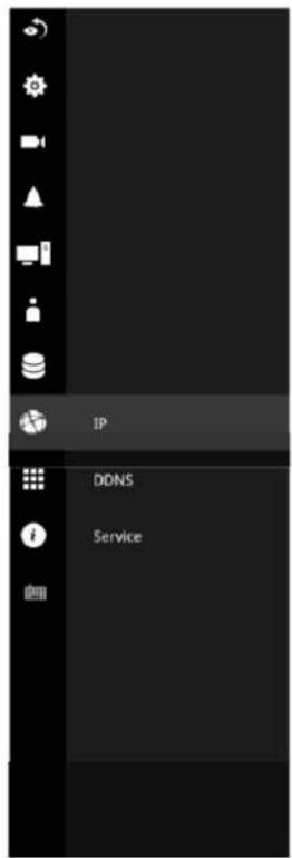
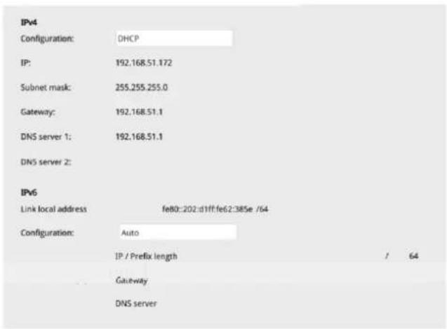
Settings - Network - IP 169
Settings - DDNS....170
Settings–Service .... 171
3-6. HTTPS certificate 175
3-7. Trend Micro IoT Security Service....176
3-8. Information 177
3-9. Limitation when working with VSS....177
Section Two: Management over a Web Console.... 178
Chapter 4: Login and Getting Started.... 179
4-1. Login....179
4-2. Graphical Layout and Screen Elements - Live view 183
4-2-1. Device List Panel 184
4-2-2. Layout 187
4-2-3. Scene 188
4-2-5. View Cell panel 189
Adding Cameras to View Cells 189
4-3. Graphical Layout and Screen Elements - Playback....196
Playback Panel....197
4-4. Graphical Layout and Screen Elements - Search 199
Chapter 5: System Settings....201
Safety and Compatibility 203

廢電池請回收
警告:
The NVR also supports the VIVOCloud Retail app. Please refer to the VIVOCloud Retail app User Guide for details.

IMPORTANT:
External Disk Usage Recommendation: We highly recommend users to utilize compliance USB3.0 cables for optimal performance and to prevent compatibility issues. In order to ensure proper detection of the external disk and achieve expected data transfer speeds, we suggest using cables with a length of 60cm or less

NOTE:
The NVR needs to store a database on the hard drives for keeping the Deep Search metadata. Such metadata will take up storage space, yet the database size will be smaller than Smart Search II.

NOTE:
- The NVR is only to be connected to PoE networks without routing to outside plants.
- For PoE connection, use only UL listed I.T.E. with PoE output.
Revision History
* Rev. 1.0: Initial release; Rev. 1.1: Fix bugs and Update content

IMPORTANT:
Avoid the following with the use of battery:
- Replacement of a battery with an incorrect type that can defeat a safeguard (for example, in the case of some lithium battery types),
- Disposal of a battery into fire or a hot oven, or mechanically crushing or cutting of a battery, that can result in an explosion,
- Leaving a battery in an extremely high temperature surrounding environment that can result in an explosion or the leakage of flammable liquid or gas, and
- A battery subjected to extremely low air pressure that may result in an explosion or the leakage of flammable liquid or gas.

IMPORTANT:
- Delete a volume erases the recordings in it.
- The lift on the 16TB volume limitation also applies to USB3.0 external storage.

IMPORTANT:
Some low quality Ethernet cables with smaller core diameter can seriously reduce the transmission rate. Use CAT5e or CAT6 cables with a wire gauge of 24AWG for NVR's uplink port. A thicker core 24 AWG network cable can offer less resistance than a 26 AWG or 28 AWG network cable.
Use shielded cables in high noise environments where cross talk and EMI can occur.

IMPORTANT:
Due to the limitation of system resources, the fisheye's all dewarp modes (including 1O/1R/1O3R/1O8R) can only take place in a 1x1 view cell, for one fisheye camera.
The onboard PoE are end-span ports.

IMPORTANT:
- Installation and maintenance service should only be performed by qualified technicians.
- At all times, maintenance of the inside of the chassis should be carried out after all power is disconnected.

NOTE:
The following are the limitations for web access using the non-IE browsers:
- Playback: fast forward, back forward, next frame buttons are not available.
- Snapshot and Auto screen ratio not available on Safari.
- Web browsers supported:
- Chrome v68.0.3440 and later official version
- Firefox v61.02 and later official version
- OSes supported
- Windows
■ Windows 7, 64 bit
■ Windows 10
-
Minimum PC hardware requirements
-
CPU: Intel i5 4th generation and higher
- RAM: 4GB and higher

NOTE:
- The NVR is only to be connected to PoE networks without routing to outside plants.
- For PoE connection, use only UL listed I.T.E. with PoE output.
NOTE:
Use the NVR only with a DC power supply that is UL listed, and limited power source (LPS) certified. The power supply should bear the UL listed and LPS marks. The power supply should also meet any safety and compliance requirements for the country of use.
The use of surveillance devices may be prohibited by law in your country. The Network Camera is not only a high-performance web-ready camera but can also be part of a flexible surveillance system. It is the user's responsibility to ensure that the operation of such devices is legal before installing this unit for its intended use.
It is important to first verify that all contents received are complete according to the Package Contents listed below. Take note of the warnings in the Quick Installation Guide before the Network Camera is installed; then carefully read and follow the instructions in the Installation chapter to avoid damage due to faulty assembly and installation. This also ensures the product is used properly as intended.
The Network Camera is a network device and its use should be straightforward for those who have basic networking knowledge. It is designed for various applications including video sharing, general security/surveillance, etc. The Configuration chapter suggests ways to best utilize the Network Camera and ensure proper operations. For creative and professional developers, the URL Commands of the Network Camera section serves as a helpful reference to customizing existing homepages or integrating with the current web server.

NOTE:
The operating system and management software are installed on a flash memory mounted on the main board. Except for running the plug-ins for the onscreen control on a web console, there is no need to install software.
Package Contents
| ■ ND9326P or ND9426P■ Power cord■ Quick Installation Guide | ■ Mouse■ Screws■ Foot pads |
Symbols and Statements in this Document

INFORMATION: provides important messages or advices that might help prevent inconvenient or problem situations.

NOTE: Notices provide guidance or advices that are related to the functional integrity of the machine.

Tips: Tips are useful information that helps enhance or facilitate an installation, function, or process.

WARNING! or IMPORTANT: These statements indicate situations that can be dangerous or hazardous to the machine or you.

Electrical Hazard: This statement appears when high voltage electrical hazards might occur to an operator.
Chapter 1: Hardware Installation and Initial Configuration
Introducing the Network Video Recorder
VIVOTEK's ND9326P and ND9426P are the H.265 Linux-based standalone NVRs with embedded PoE. Equipped for up to 8-CH/16-CH network cameras, the NVRs support 8x or 16x 802.3 at/af PoE ports. Both also display the PoE power information, providing for a more convenient and smarter installation.
The NVR also supports remote and mobile access via VORTEX Connect, VIVOCloud, and iViewer apps for both iOS and Android handheld devices. The VIVOCloud app provides instant push notification and direct video playback functions when triggered by an alarm notification, providing users with a flexible and intelligent NVR for seamless use in small to medium sized video surveillance applications.
With H.265 compression technology and embedded with 2 HDD's providing up to 16TB of storage age space, the NVR offers greater than 30% more recording capacity than H.264 systems. This advancement provides users with more storage space for longer durations of video recording. In addition, the RAID 0/1 configurations provide further data security in the rare event of a hard drive failure.
For high-quality and detailed images, the NVR supports a maximum network camera resolution of 4K,20-Megapixels. Furthermore, the NVR supports VIVOTEK's fisheye network camera "Fisheye Dewarp" function via a web console, which provides multiple de-warping modes in live view and playback, ensuring the correct angle of video view and detailed information for flexible usage. Lastly, to quickly and intuitively find any target event, the NVR is equipped with the "Story-Board Search" function, which provides a glimpse of past recordings over an intuitive time-line.
The NVR supports HDMI and VGA local video output, so users can control the GUI OSD interface via mouse & keyboard, eliminating the need for a separate PC to search video or playback from the NVR. Additionally, the intuitive and friendly VIVOTEK GUI design gives users a smoother control experience.
Special Features
- Runs on embedded Linux
- 1 x HDMI and 1 x VGA for local display
- 2 x HDD bay
- 2 x Gigabit RJ45 Ethernet port for uplink;
- 3 x USB Ports (1 USB 3.0 in front and 2 USB 2.0 in Back)
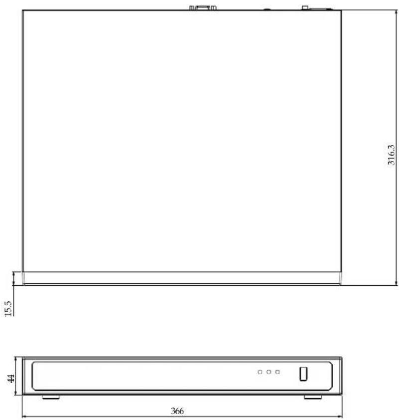
- Size: 365 mm (W) x 315 mm (D) x 44 mm (H). Weight: 2.65 (9326P) 2.78kg (9426P, w/o HDD).
-
8- or 16-CH Live View & 4-CH Synchronous Playback (web console)
• H.265 / H.264 / MJPEG
• Supports RAID0 and RAID1 volume configuration. -
PTZ Support
- Snapshot / Export Media
• Digital zoom Video Control
• VORTEX Connect and VIVOCloud for effortless access from smartphones using a QR code - Terminal block pins for DI/DO connection.
- Configuration Backup / Restore
- Compatible with VIVOTEK VSS Central Management Software*
- Integration with VIVOTEK Network Cameras
• VIVOTEK iViewer Support (iOS/Android smartphones/hand-held devices)
*The VIVOTEK VSS Central Management Software is not included in the package.
The NVR can be part of a Social Distancing solution. Below is a short introduction.
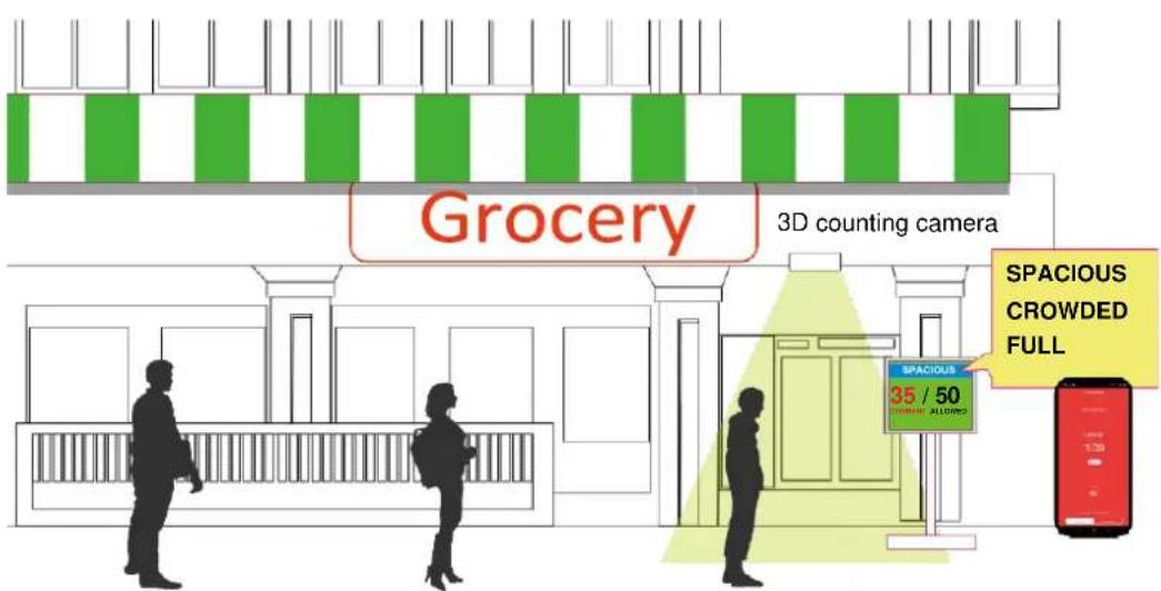
Facing the pandemic outbreak of coronavirus, many governments imposed social distancing methods to reduce the risk of contraction. One method is to control the number of visitors inside a building while allowing people to work or purchase necessities. Using the 3D people counting cameras at the entrance and exit of a facility, the current occupancy number can be displayed at the store front.
You can configure an occupancy limit and display the message when the limit is reached. Instead of having a security personnel to count the number, the solution can help control the customer traffic.
The solution enables the following:
- Accurate counting of people entering or leaving a facility.
- Displays the occupancy number on an HDMI monitor.
- Business owners can transfer the solution into the V O RT EX Co n ne ct or VIVOCloud Retail solution when social distancing becomes unnecessary.
- Notification to a smartphone app via the VORTEX Connect or VIVOCloud utility.
The Social Distancing package comes with the following components:
- 1 or multiple SC8131 3D counting cameras.
2.1 PoE switch
3.1 NVR
* The Ethernet, HDMI cables, and HDMI extenders are user-supplied.
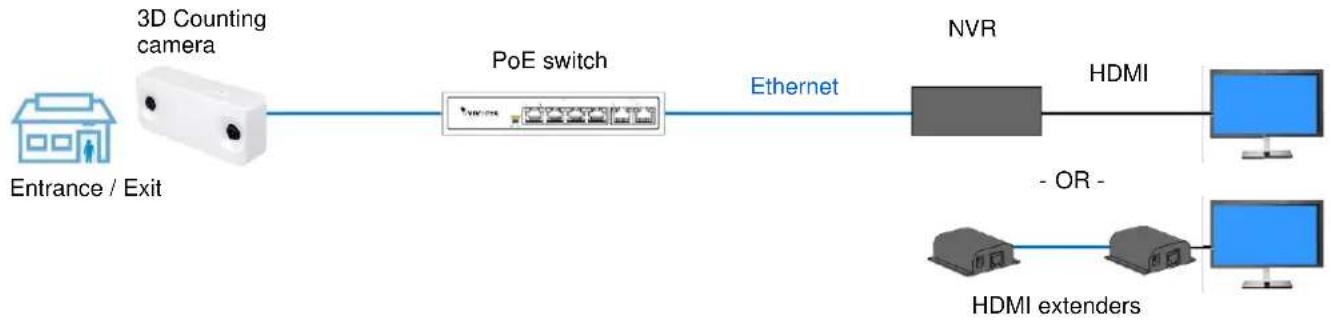
flowchart
graph LR
    A["Entrance / Exit"] --> B["3D Counting camera"]
    B --> C["PoE switch"]
    C --> D["Ethernet"]
    D --> E["NVR"]
    E --> F["HDMI"]
    F --> G["+"]
    G --> H["HDMI extenders"]
    H --> I["- OR -"]
Safety
■ Connect the system to an earthed main power outlet.
■ Never open the housing of the power supply unit.
■ Install and operate the system only in a dry, weather-proof location.
■ Observe the following safety factors:
• Is there visible damage to the system or power cord?
• Is the system operating correctly?
• Has the system been exposed to rain or moisture?
- Has the system been in a long storage under harsh conditions or exposed to unconforming stress?
■ The relevant electrical engineering regulations must be complied with at all times during installation.
■ Ensure that all maintenance and repair work is handled by qualified personnel such as electrical engineers or network specialists.
- Read this manual before installing or operating the system. The documentation contains important safety instructions about permitted uses.
■ The rated AC input is: 100-240V\~3.5A, 60-50Hz; the max. consumption: 190W (ND9326P), 270W (ND9426P).
■ If a fault occurs, disconnect the power cord from the power supply.
■ Do not install the system close to heaters or other heat sources. Avoid locations with direct sunlight.
■ All ventilation openings must not be blocked.
■ Use only the cables shipped with system or use appropriate cables that can withstand electromagnetic interference.
Chassis Dimensions
Physical Description

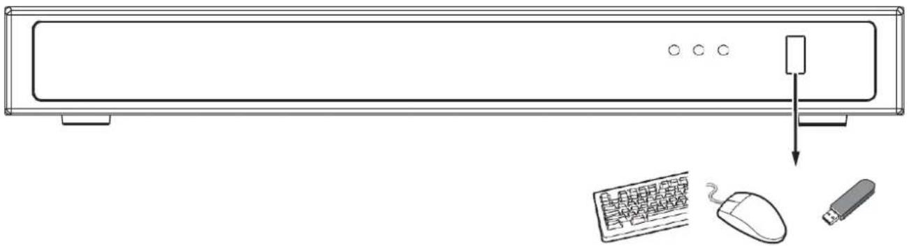
Front View
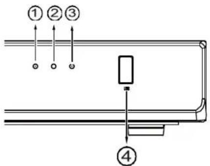
| 1 | Network uplink status/activity LED |
| 2 | System status LED |
| 3 | System power status |
| 4 | USB 3.0 port |

Rear View
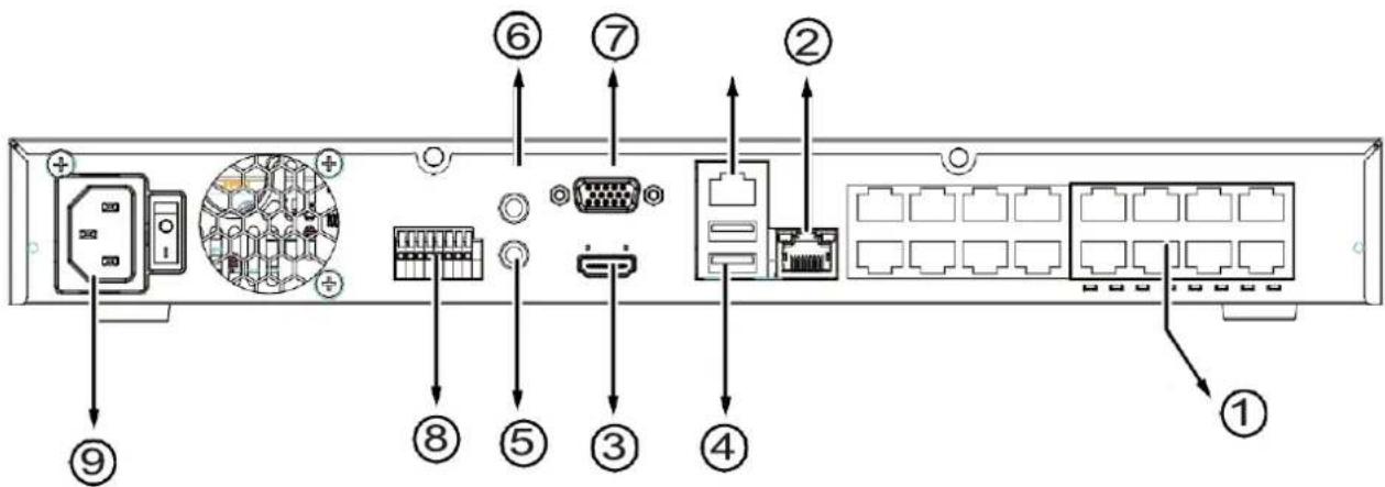
| 1 | PoE ports # 1 to #16 (ND9426P) | 6 | Audio OUT |
| 2 | RJ45 port - GbE uplink | 7 | VGA |
| 3 | HDMI | 8 | DI/DO terminal block |
| 4 | USB 2.0 port | 9 | Power socket (110/240V AC), w/ a power button |
| 5 | Audio IN |

IMPORTANT:
The total power budget for the ND9326P's 8 PoE ports is 120W.
The total power budget for the ND9426P's 16 PoE ports is 200W. Every 8 ports (#1 \~ #8 or #9 \~ #16) provides 100W.
Please ensure the camera PD specifications meet the NVR PSE power supply specification before installation.

NOTE:
You can also use the Reset button to restore system defaults. Press and hold down the button for longer than 5 seconds. The system should start restoring defaults.

IMPORTANT:
It is important to leave a clearance of 25cm behind the chassis. The clearance is required to ensure an adequate airflow through the chassis to ventilate heat.
To ensure normal operation, maintain ambient airflow. Do not block the airflow around chassis such as placing the system in a closed cabinet.

natural_image
Diagram of a rectangular device with circular holes and a 25cm dimension label (no text or symbols on the device itself)Hardware Installation
SATA hard disk(s) are user-supplied. The network video recorder can readily accommodate most of the off-the-shelf SATA hard drives.
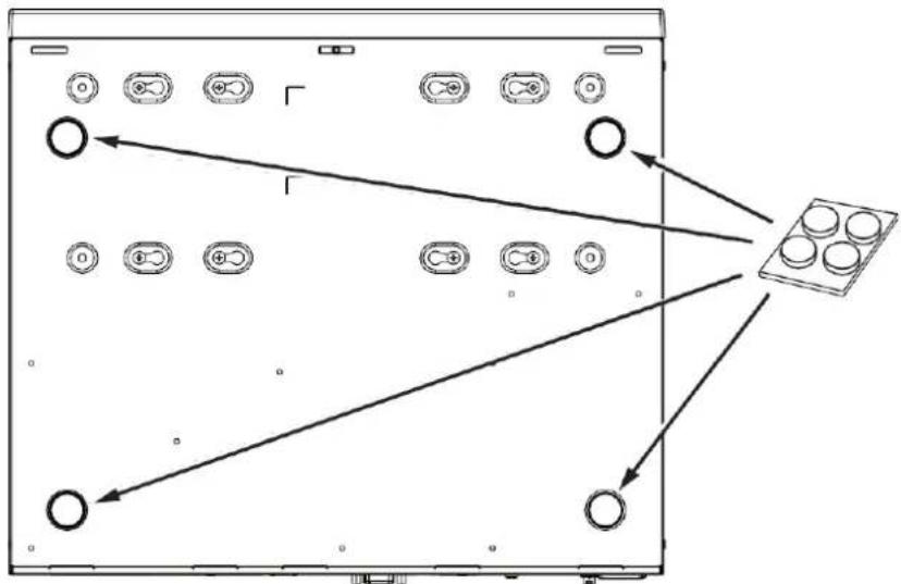
- Attach 4-foot pads to the bottom of the enclosure.
flowchart
graph TD
    A["Device Panel"] --> B["Display Unit"]
    A --> C["Component 1"]
    A --> D["Component 2"]
    A --> E["Component 3"]
    A --> F["Component 4"]
    A --> G["Component 5"]
    A --> H["Component 6"]
    A --> I["Component 7"]
    A --> J["Component 8"]
    A --> K["Component 9"]
    A --> L["Component 10"]
    A --> M["Component 11"]
    A --> N["Component 12"]
    A --> O["Component 13"]
    A --> P["Component 14"]
    A --> Q["Component 15"]
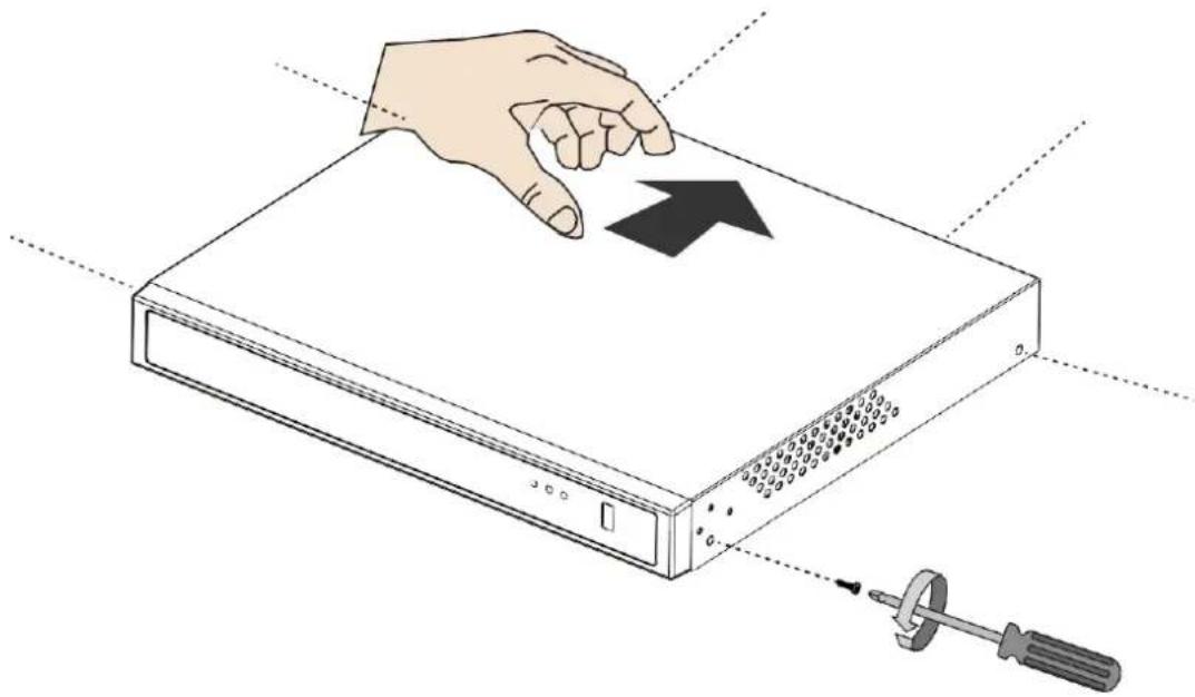
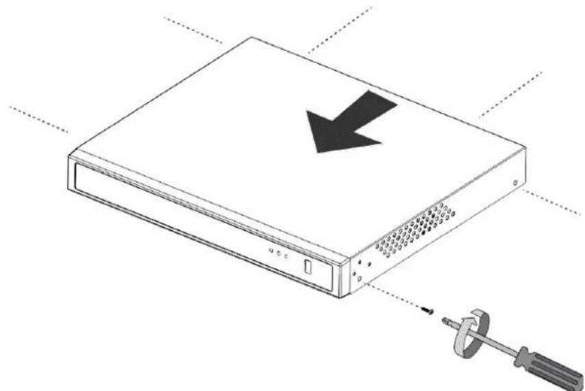
- Use a screwdriver to loosen the retention screws on the sides and the back of the chassis. Slide the top cover back, and then remove the top cover.
natural_image
Illustration of a hand pressing down on a server rack with a pointing arrow, next to a screwdriver (no text or symbols)- Connect SATA data and power cables to the main board.
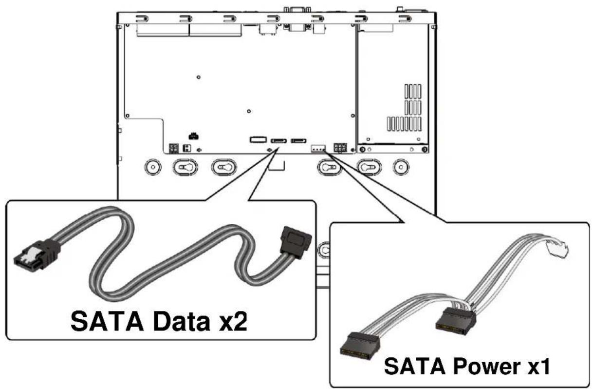
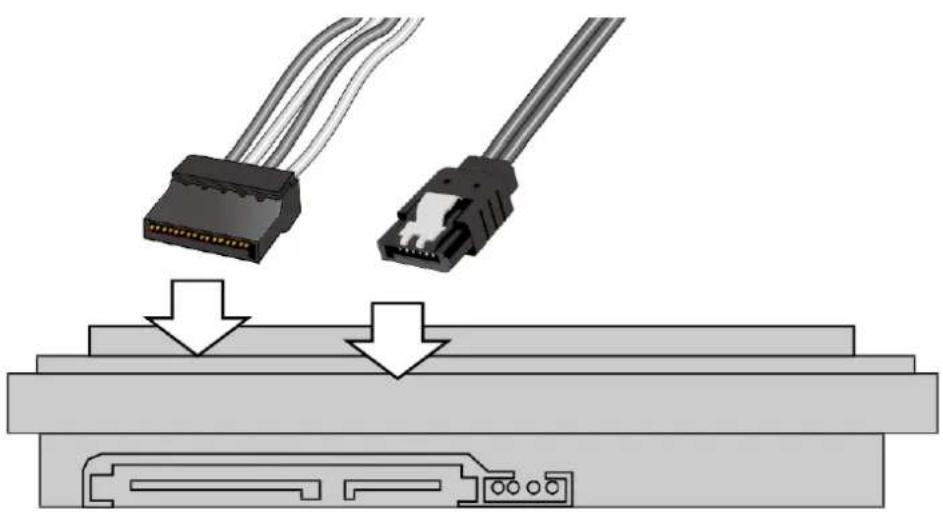
- Connect the SATA power and SATA data cables to the hard disk drives.
natural_image
Diagram showing two connected electronic devices (HDRs) with cable routing, no text or symbols presentSATA power SATA data
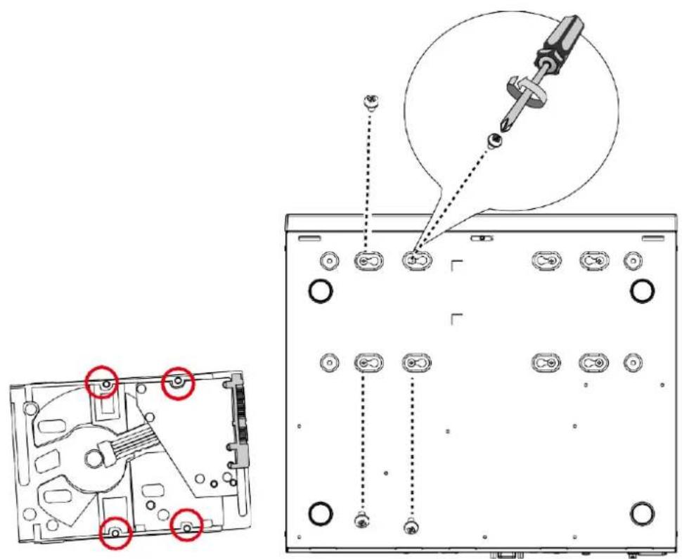
- Install hard drives to the chassis. Note that the screws pass through the bottom of the chassis and secure the hard drives using the mounting holes at the bottom of hard drives. When installing hard drives, their label side should be facing up, and the connector side facing the inside of the chassis.
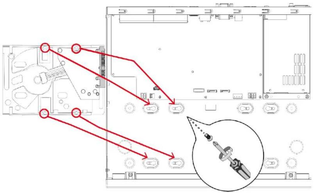
When securing screws to the hard drives, do not completely fasten the screws. Fasten the screws halfway and insert the screw heads into the key slot holes. When they are in place, fasten the screws from the bottom of the chassis.
- Secure the hard disks to the mounting positions in the chassis with its label side facing up, and the connectors facing the inside of the chassis. The sample drawing below shows the positions.
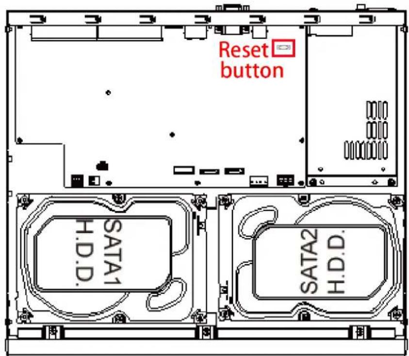

NOTE:
You can also use the Reset button to restore system defaults. Press and hold down the button for longer than 5 seconds. The system should start restoring defaults.
- When done, install the top cover.
natural_image
Illustration of a server rack with a downward arrow and a screwdriver inserted, no text or symbols present.Rack-mounting (Optional, and the rack-mount brackets are separately purchased)

IMPORTANT:
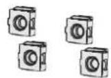
If you have either a round-holed or square-holed rack, install cage nuts or clip nuts to the desired positions on the rack posts.
The instructions below are based on the installation to a 4-post equipment rack.
The slide rails apply to rack cabinet of a depth of 700 to 900mm. With 2 hard drives, the chassis can weigh up to 4kg.
If you need to install the NVR system into a rack cabinet,
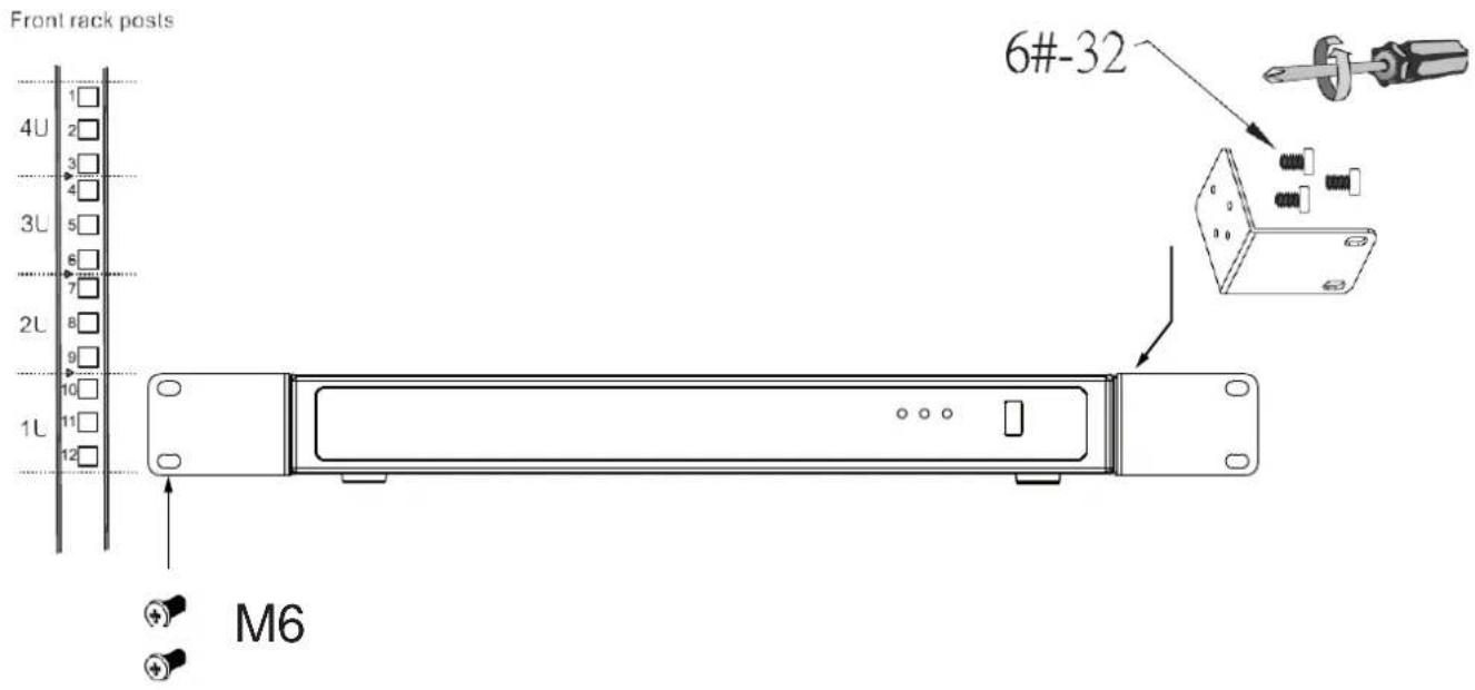
- Secure the brackets to the sides of the chassis by driving 3 included screws.

natural_image
Technical line drawing of a rectangular electronic device with circular components and directional arrows (no text or symbols)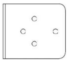
natural_image
Simple geometric diagram with four circles arranged around a central point, enclosed in a rounded rectangle (no text or symbols)6#-32
- Secure the chassis to rack posts using 2 M6 screws on each side.
Interface Connections
- Connect to a monitor using an HDMI cable. VGA is also supported.
- Connect CAT5e or better-quality Ethernet cable to the GbE Ethernet ports.
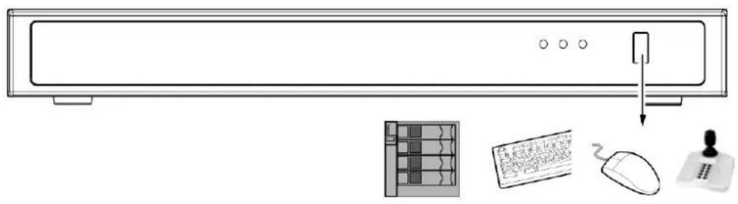
- Connect USB devices such as, mouse, keyboard, USB optical drive, or USB thumb drive (formatted in FAT format), joystick, or UPS.
- Connect external devices, such as sensors, relays, or alarms to the terminal block.
- Connect the system to the power mains.
natural_image
Line drawing of a computer monitor with a keyboard, mouse, and USB port (no text or symbols)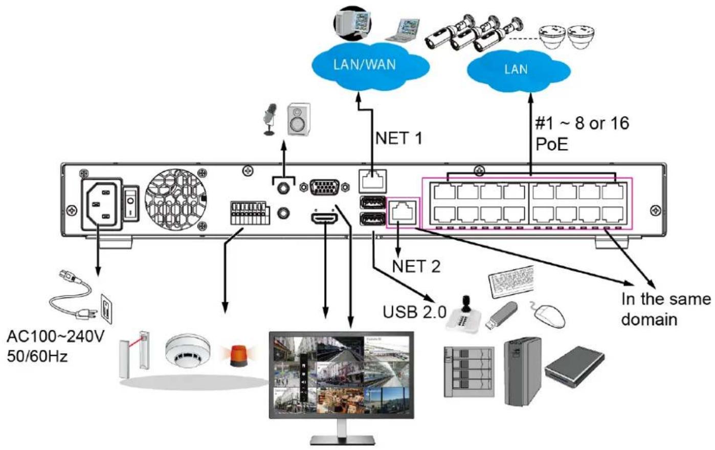
flowchart
graph TD
    A["AC100~240V 50/60Hz"] --> B["Monitor"]
    B --> C["USB 2.0"]
    C --> D["Net 1"]
    D --> E["LAN/WAN"]
    D --> F["LAN"]
    D --> G["#1 ~ 8 or 16 PoE"]
    D --> H["In the same domain"]

Please do not connect the NVR's PoE ports to non-PD ^+ devices (such as an Ethernet switch LAN port). The Ethernet control circuits may not be compatible.
* PD = A Powered Device designed to receive power source from a PoE connection such as network cameras.

NOTE:
- PoE ports are in the same network domain as NET 2.
• NET 1 and NET 2 reside in different subnets. - NET 2 resides in the same subnet of the onboard PoE ports. If a user prefers to access the PoE powered cameras using 3rd-party devices, he/she can connect to the NET 2.

NOTE:
- The onboard DHCP server provides IPs for the connected PoE cameras (10.1.1.1 or 192.168.2.1 onward). The uplink Ethernet port acquires a different IP from the network it connects to. The PoE ports and the uplink are in separated networks.
If your uplink port happens to connect to a 10.1.1.x network, make sure you change your PoE subnet to 192.168.2.x segment.
Although the system supports MAC Binding, the system should be able to detect VIVOTEK's cameras within the network regardless of the presence of a DHCP server.
POE DHCP:
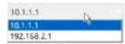
2-1. If external USB 3.0 storage is attached, a volume size larger than 16TB is supported. The NVR supports the connection to a USB3.0 storage with a maximum of 5 disk drives. The minimum storage size in the external storage is 64GB.
2-2. The external storage must be powered on first before the NVR.
2-3. Hot-swapping is not supported. If the external storage is disconnected, recording will be continued using the NVR's internal disk drives.
2-4. The storage configuration on the external storage is separately configured, e.g., RAID configuration. The RAID volume on the external storage appears to the NVR as a single large disk drive, and you should create a volume from it from the Storage configuration page.
2-5. If the disk drives in the external storage are not configured into the NVR's storage volumes, you can use them as the external backup devices. To do so, you should format disk drives in the external storage in the FAT32 or NTFS format, and export the recorded video on NVR to these disk drives.
2-6. Limitations:
- When you are exporting video to the disk drives in an external storage, you cannot select the other disk drives to create a new volume.
- If the disk drives or volumes in the external storage is smaller than 1TB, you cannot configure them as volumes for the NVR.
- The connection interface to external storage must comply with the USB 3.0 specifications.
2-7. The RAID or volume configuration in the NVR does not extend to include devices in the external storage.
Terminal Block Connections
The terminal block pinouts is shown as follows:
The relay pins default status is set to Normally Open. Connect your relay or external devices' signal wires to the system, the system will automatically detect the current signal status. You can then trigger the external devices using the DI/DO panel on the live view.
You can also configure the system alarm setting for the system to automatically trigger a relay pin on the occurrence of system events. See Alarm settings on page 118.
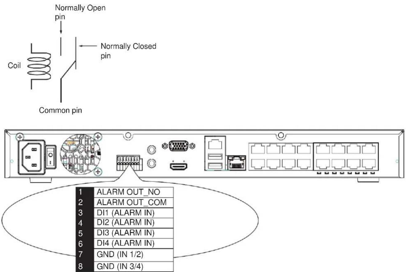
The GND are common ground for theDIs.

WARNING:
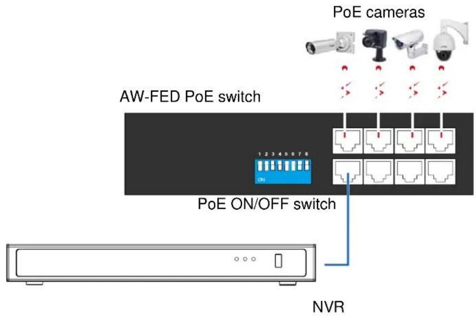
If you connect the NVR to a PoE port of the AW-FED series PoE switch, make sure you turn off the PoE output on that specific port using the onboard DIP switch. Otherwise, the high-power output can damage the LAN port on NVR.
Limitations on text entry length:
* User account: 64 alpha-numeric characters
* Account password: 64 alpha-numeric characters
* Path name: 256 alpha-numeric characters
* Supports all printable ASCII (0x21-0x7E) characters and space (ox20) for password.!"#\$%&\'()*+,-./0123456789:;<=>?@ABCDEFGHIJKLMNOPQRSTUVWXYZ[]^_^`abcdefghijklmnopqrstuvwxyz{|}\~
* IP domain name: host.xxx.yyy.zzz - 63 bytes; total: 253 bytes
* Email account: local@domain_name_part - local -63bytes domain_name_part - 253 bytes.
Initial Configuration - via a Local Console
A local console requires the following:
- A monitor is connected via an HDMI or VGA cable.
- A mouse and/or a keyboard are connected to the system.
- It is presumed that the system has not been configured yet.
Follow the onscreen messages to complete the initial configuration:
You should create a password for the protection of your system first. Use the combination of alphabetic, numeric, and special characters of at least 8 characters to create a password of reasonable strength.
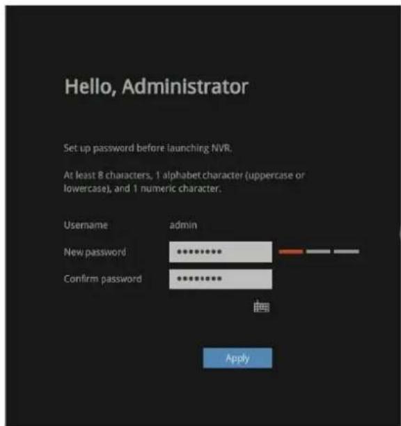
- Select the UI language, Time zone, and current date and time. Click on the Continue button to proceed. Make sure you enter the correct date and time.
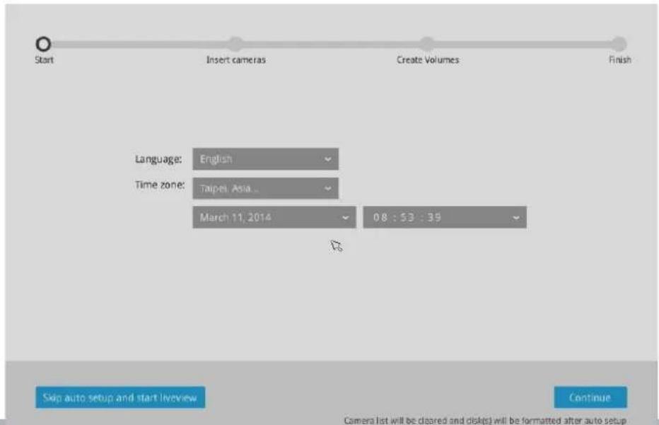

IMPORTANT:
Except in the initial setup, changing system time can produce disruptions to the existing recordings. Turning the current system time back to a time when video recording was taking place can generate duplicate files. And those files may not be playable.
- The system will then start to scan the local subnet for connected cameras.
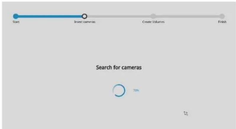
flowchart
graph LR
    A["Start"] --> B["Insert cameras"]
    B --> C["Create Volumes"]
    C --> D["Finish"]
    E["Search for cameras"] --> F["70%"]
- All cameras detected on the network will be automatically selected. If necessary, deselect the cameras you want to exclude from the configuration. Click Continue to proceed.
The NVR will automatically change the camera streaming settings. Please do not skip the add camera process in the setup wizard.
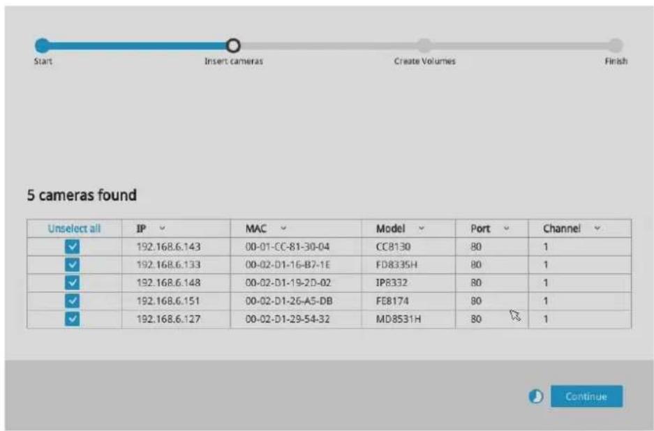
The cameras connected to the NVR PoE ports are placed behind a default gateway 10.1.1.1 or 192.1682.1.

NOTE:
- The maximum decoding bandwidth is:
H.265 Up to 1080P@480fps
H.264 Up to 1080P@480fps
Pre-recording: 5 seconds (max. 10)
Post-recording: 20 seconds (max. 300)
When cameras are recruited into the configuration, their stream 1 is used as the recording stream.
The resolution and fps (frame rate per second) of stream 1 may vary depending on the specifications of different cameras.
- If there are less than 8 or 16 cameras, the Auto Setup will automatically move to the next configuration step.

NOTE:
If the need should arise, you can manually enter an IPv6 address to recruit a camera.
Note that currently you cannot search a camera with an IPv6 address in the device search panel.

Note the following when using IPv6 addresses:
- Abbreviation is supported, e.g., for 0000:0000.
-
If illegal characters are entered, conflict warning messages will display.
-
The system will automatically create volumes from the installed disk drives. The process will take several minutes. Hard disks will be configured into single-disk volumes. You can delete these volumes and then create RAID volumes in the Settings > Storage page.
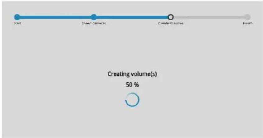
flowchart
graph LR
    A["Start"] --> B["Insert cameras"]
    B --> C["Create Volumes"]
    C --> D["Finish"]
    style A fill:#fff,stroke:#000
    style B fill:#fff,stroke:#000
    style C fill:#fff,stroke:#000
    style D fill:#fff,stroke:#000
    note bottom
        Creating volume(s)
        50 %
- Now, you can download and install the VORTEX app from App Store or Google Play.
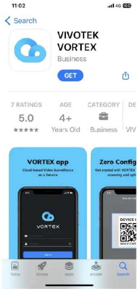
natural_image
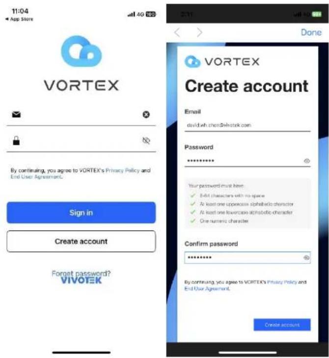
Vortex logo icon with abstract blue cloud-like design on white background (no text or symbols)5-1 Tap Create account, enter your email address and password, and tap Create account.
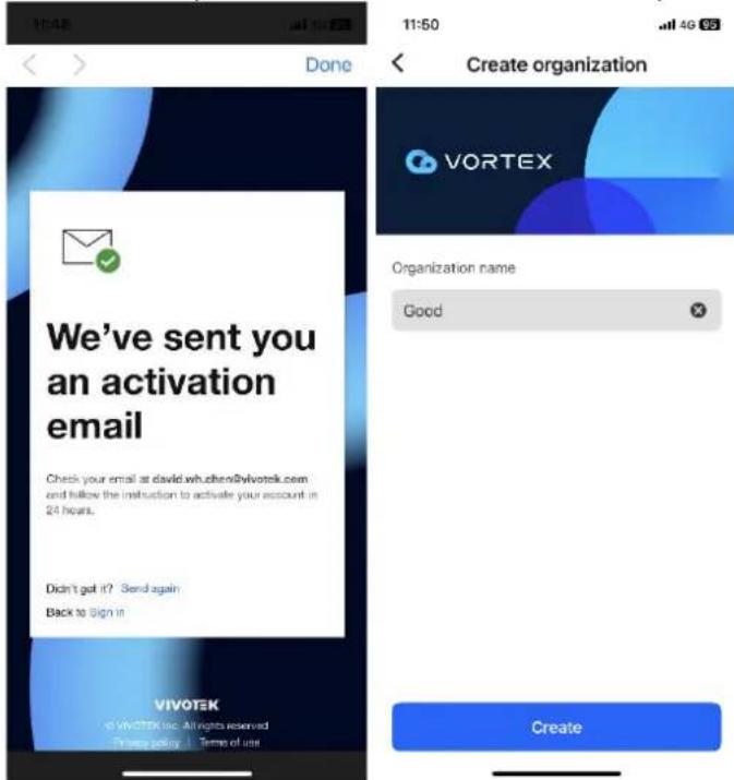
5-2 Confirm your email address to activate your account, and then create an organization name.
5-3 Tap Add devices and scan the NVR's QR code, which can be obtained either from the end of the NVR's auto setup process or by adding a device with VORTEX Connect device ID.
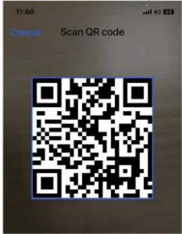
Please scan the QR code on the device. And make sure the code is steady and well-it.
Help me find the code
Enter device ID
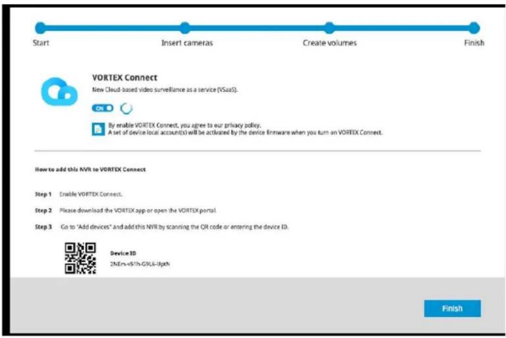
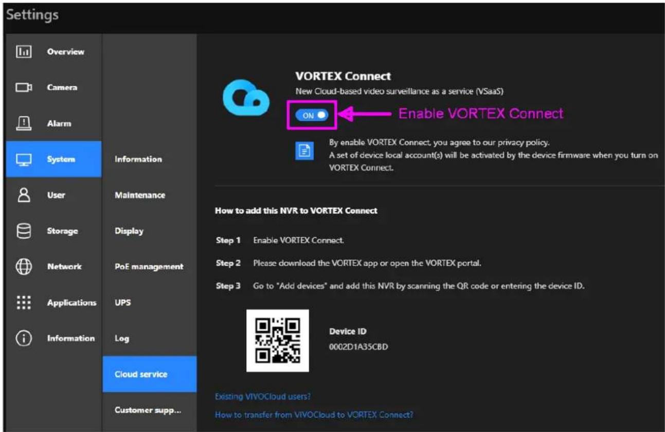
5-4 After scanning the QR code, a Device ID page displays. Then, tap Add and Done.
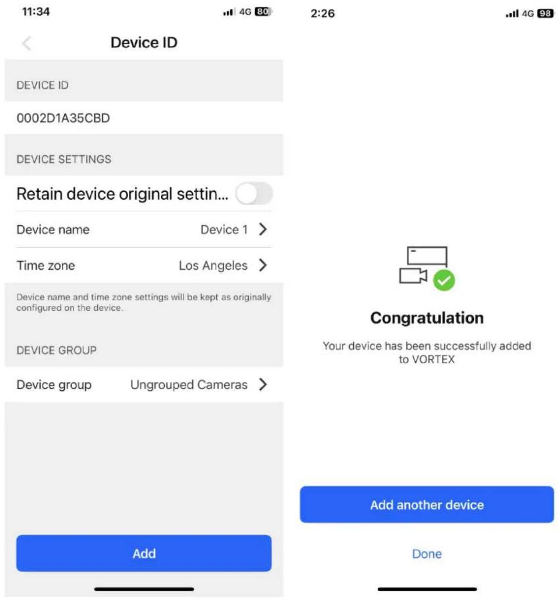
5-5 Please visit the VORTEX FAQ section https://vivotek.zendesk.com/hc/en-001/sections/16268878708633-VORTEX for more information on how to use VORTEX Connect.
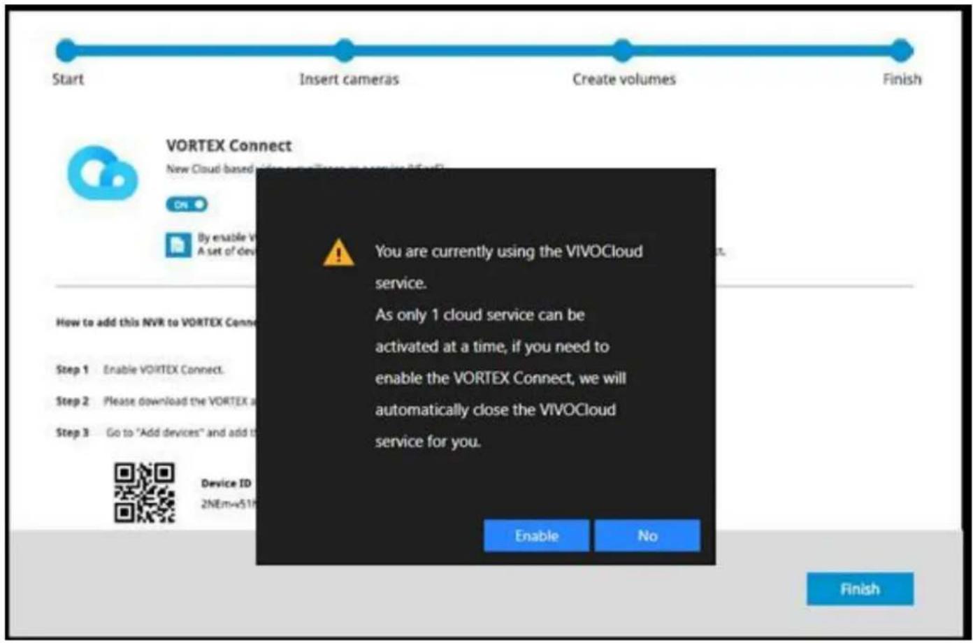
In addition, if you are an existing VIVOCloud user and want to continue using this service, click No in the following dialog box.

NOTE:
For VIVOCloud and VORTEX Connect cloud services, you can only activate/enable one cloud service at a time.
- Another optional utility, VIVOCloud, is available through the Apple and Android App Stores too. The VIVOCloud works with a server hosted by VIVOTEK for bridging and tunneling video requests between client devices and network cameras/CMS/NVR. The utility simplifies and facilitates network configuration for access across the Internet.
The prerequisites for using the VIVOCloud are as follows:
- Download and install the VIVOCloud utility to your cell phone.
- Both the NVR and your cell phone have access to the Internet.
With this utility, you do not need to configure IP port forwarding on router or set up a DDNS address for the NVR. You do not even need to know the IP address of the NVR. The VIVOCloud utility automatically manages the network parameters required for making the connection. The VIVOCloud comes with viewing and playback interfaces very similar to those in the iViewer utility.
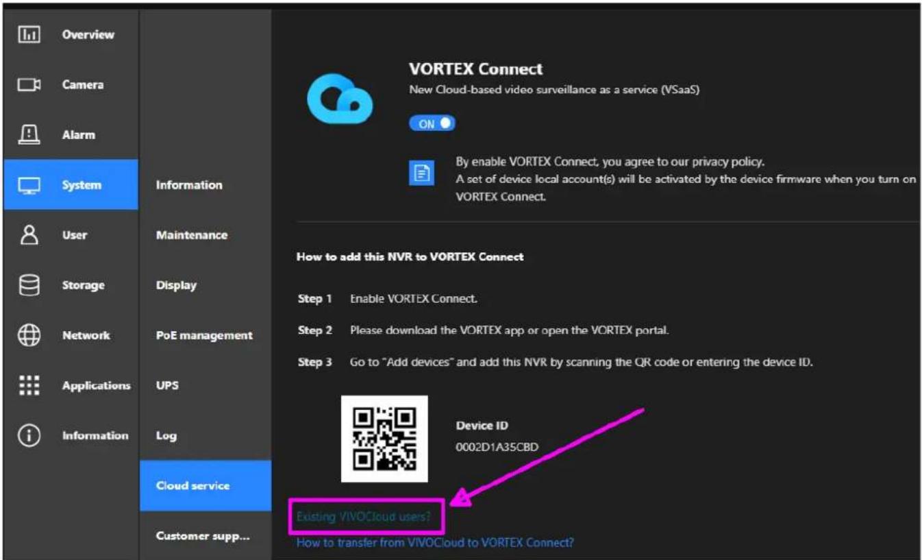
If you are an existing VIVOCloud user, on the NVR screen, click System > Cloud service > Existing VIVOCloud users.
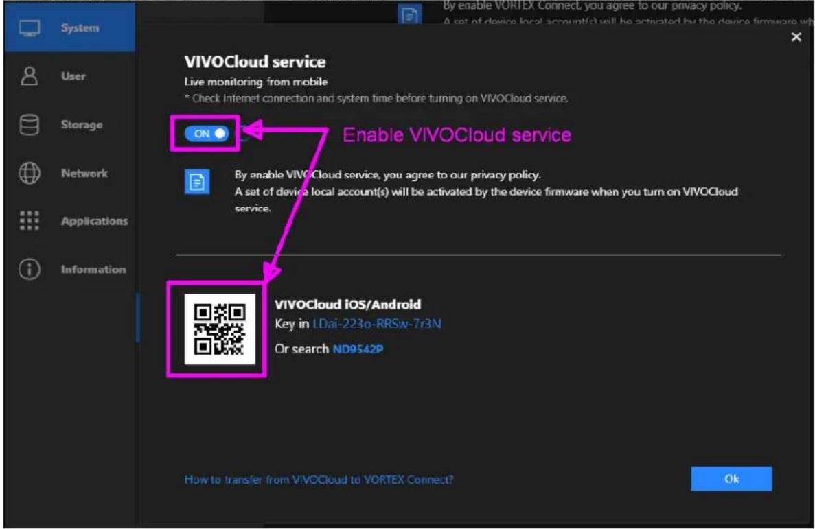
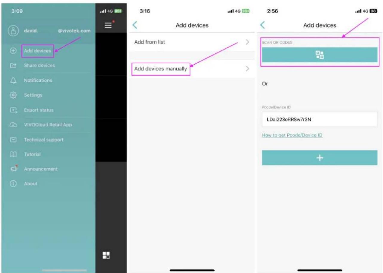
Next, enable VIVOCloud. Then, tap Add devices > Add devices manually > SCAN QR CODES to scan the QR code from within the VIVOCloud app and wait for the connection process to complete.
LED Indicators
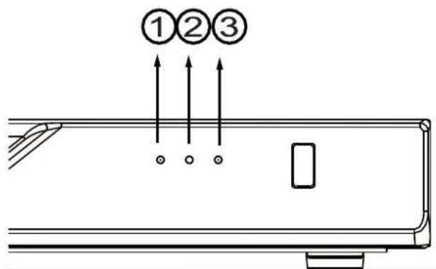
| Name | Behavior | Definitions | |
| 1. NET LED | 1 | Blinking Green | Data is being transmitted or received. |
| 2 | OFF | The Ethernet uplink NET1 or NET2 is disconnected. | |
| 2. Status LED | 1 | Constant Green | System ready. |
| 2 | Blinking Green every 1 second | Updating firmware or device pack. | |
| 3 | Constant Red | 1. S.M.A.R.T.-related disk errors,2. A configured H.D.D. is missing,3. H.D.D. is full. Buzzer will also be sounded. When buzzer is turned off, LED will return normal. | |
| 3. Power LED | 1 | Solid Green | The NVR is powered on. |
| 2 | OFF | The NVR is powered off. | |
This page is left blank intentionally.
Power Up and Power Down
To power up and power down,
On the initial configuration:
- Connect the power cord between the system and power outlet.
- Turn on the system using the power button on the back of chassis.
After the initial connection,
Use the power down button on the lower right corner of the Settings page. The system should start flushing the cached contents in system memory and gracefully shut down. You should then flip the power switch button on the back of chassis to completely shut down the system.
Press the Reset button for longer than 5 seconds can restore system defaults.

WARNING:
- No storage system is completely fail-safe. Damage to data might occur due to file system corruption, operating system malfunction, virus infection, HDD component failures, and so on. Therefore, it is highly recommended to regularly back up your data, and VIVOTEK disclaims responsibilities of data loss or recovery.
- Always power off the system using the power button on the back of chassis. The system is powered off when you observe that all LEDs go off. Do not disconnect the power cord while the system is still operating. Doing so will result in data inconsistencies. The normal power-off procedure allows cached data to be written to disks.

NOTE:
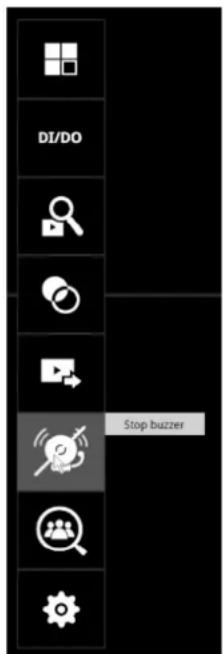
If system buzzer is sounded, move your mouse cursor to reveal the main screen portal, and then click on the Stop buzzer button.
Serious system faults, such as a missing volume, can trigger the system buzzer. Verify the cause of system fault and turn off the buzzer.
Configuring Crowd Control Solution
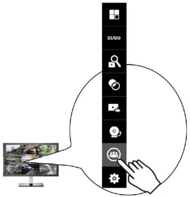
- On the desktop, move your mouse to reveal the main portal. Click on the Crowd Control button at the bottom.

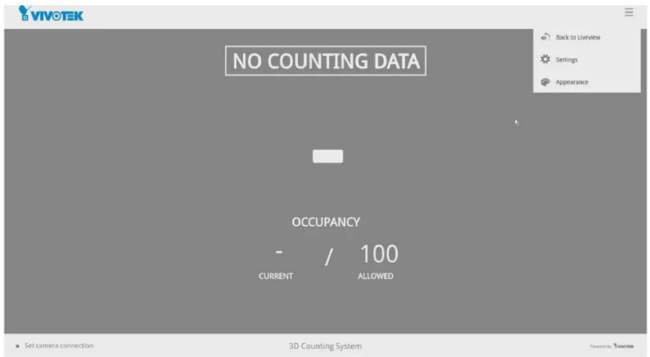
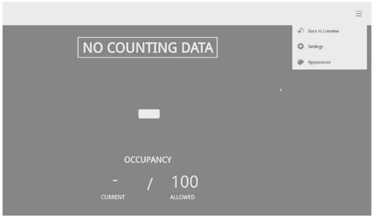
- If no human traffic has occurred, the NVR will return NO COUNTING DATA.
If there are people crossing the counting area and no counting data is shown, you should examine your configuration and the camera connection in your NVR.

NO COUNTING DATA
OCCUPANCY

/100
CURRENT
ALLOWED
3D Counting System
Towers by 2007
- Click on the CURRENT number.
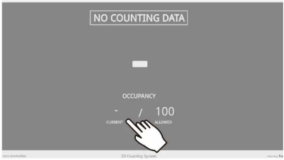
- Enter the number of your staff members. You can enter this number before you open a store for business.
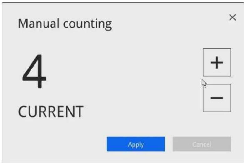
- The system will return 4 as the current occupancy.
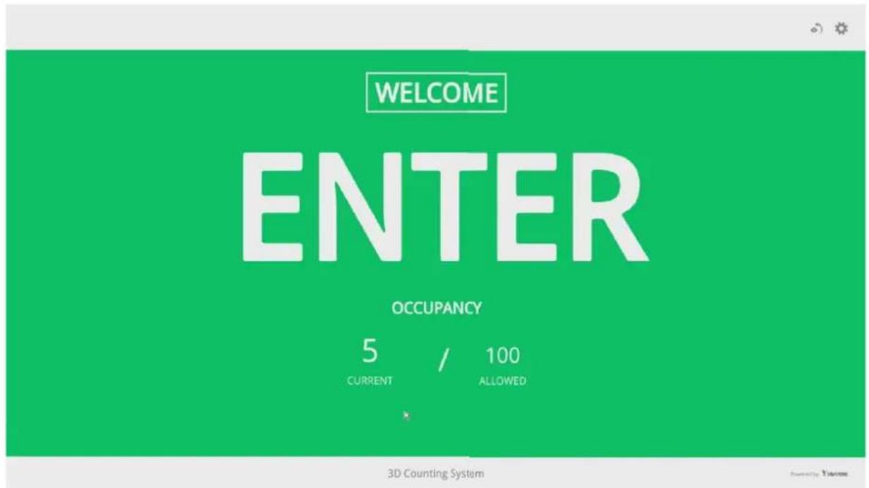
- Click on the Settings button to reveal the Settings option.
Configure each parameter for your store/facility.

Allowed occupancy: Enter a number for the maximum number of people to be present in your facility.
Show on counting page:
Current occupancy - how many people have entered your facility.
Available occupancy - the number of people who can enter without exceeding the maximum number.
Allowed occupancy:
Displays the maximum number of people allowed to enter the facility.
Scheduled reset:
You can use a scheduled reset to clear the counting results (who entered and left, and how many are there in a building) when your store/facility is closed.
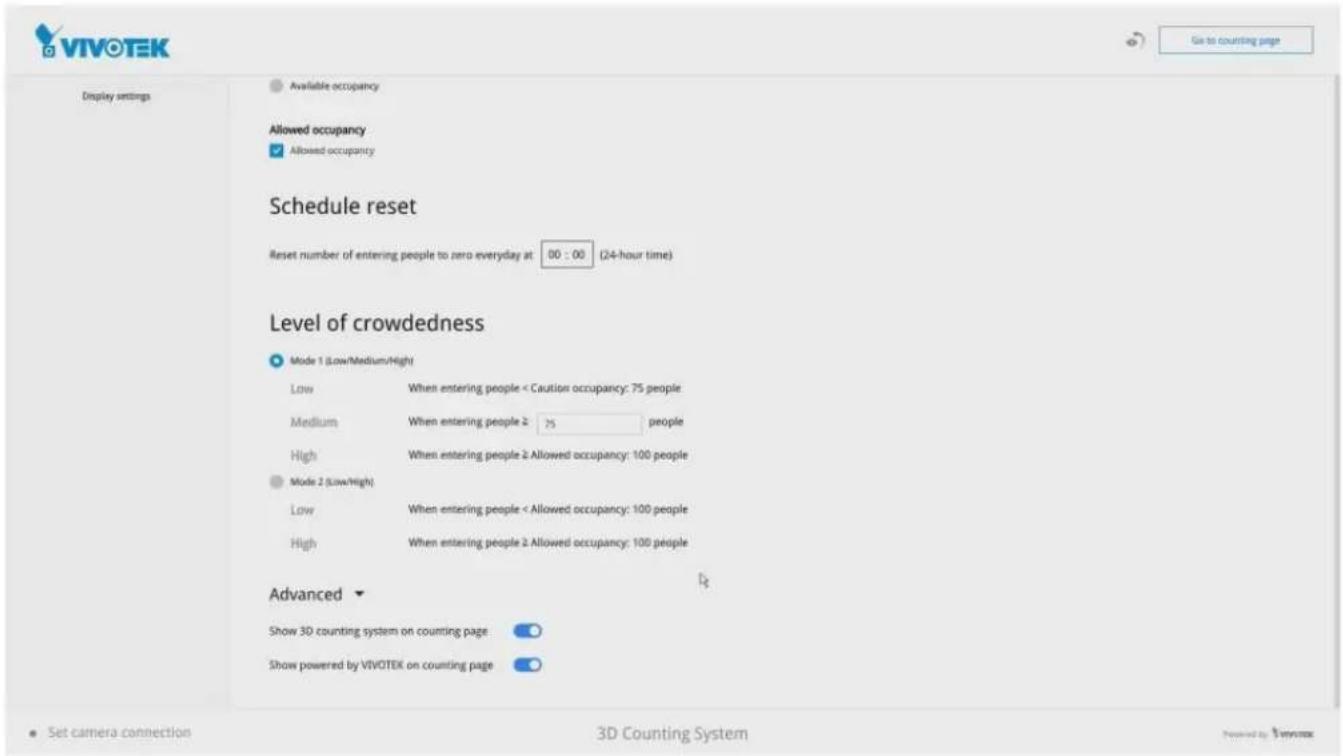
Level of Crowdedness:
Mode1 -
Low - the number of people in a building is lower than 75% of the max. allowed. Medium - the number of people in a building reached 75% of the max. allowed. High - When the max. number threshold is breached.
Mode2 -
Mode 2 only displays Low or High statuses.
Low - the number of people is lower than the max. allowed.
High - When the max. number threshold is breached.
Advanced:
Show 3D counting system on counting page - Displays 3D counting system information. Show Powered by VIVOTEK on counting page - Displays Powered by VIVOTEK wording on the counting page.
Configuring Alarm Notification:
- From the Live view, enter Settings > Alarm. You need to enter the system credentials to enter the system settings page.
Enter a name for your alarm configuration, e.g., Alarm from Crowd Control site 1.
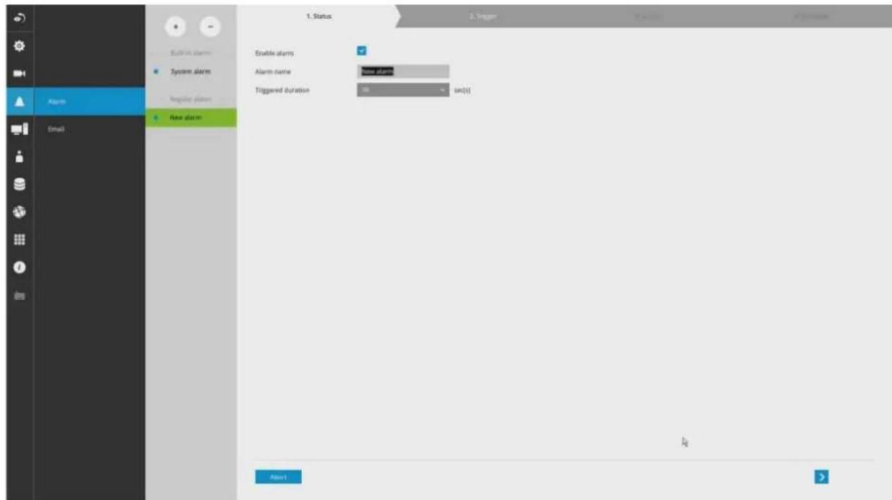
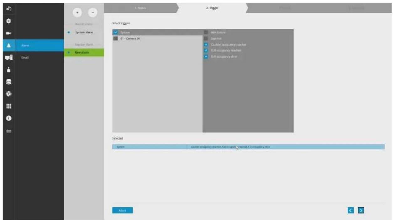
- Select Caution occupancy reached, Full occupancy reached, and Full occupancy clear.
Click on the next button at the lower right.
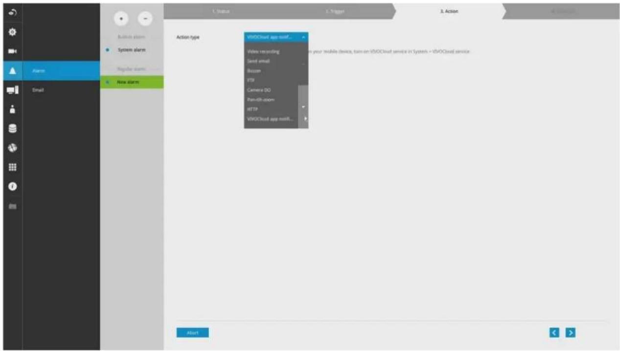
- Select VIVOCloud app notification. This way, you can receive occupancy notices using your cell phone. Click next to proceed.
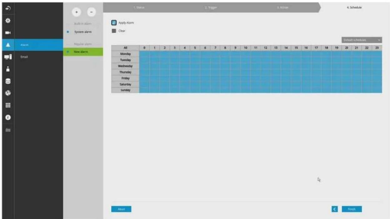
- If preferred, configure a scheduled period of time during which the alarm notification will take effect. The default is all time.
Click Finish for the configuration to take effect.
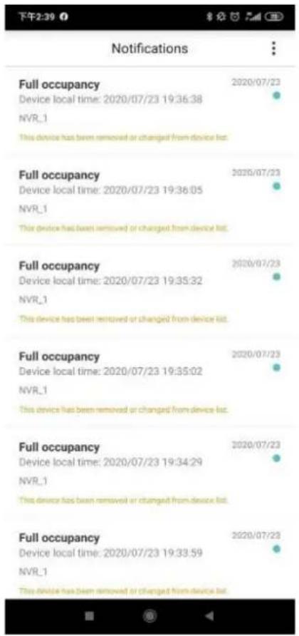
- If an alarm is triggered, e.g., the occupancy level has been breached, you can receive instant notice through the VIVOCloud app.
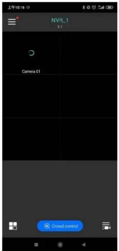
On the VIVOCloud app connected to a Crowd control solution, you can see the Crowd control button.
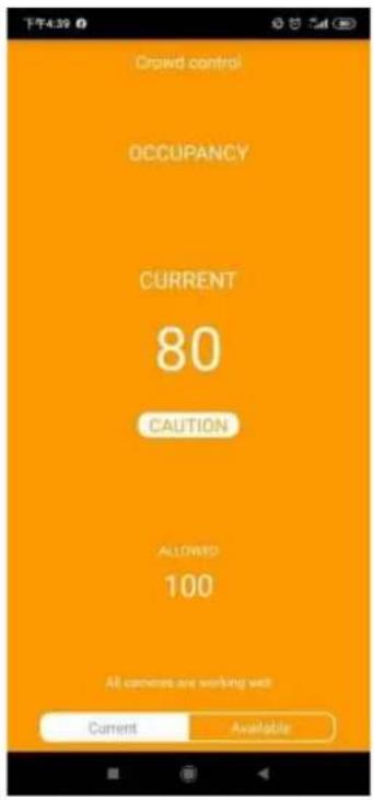
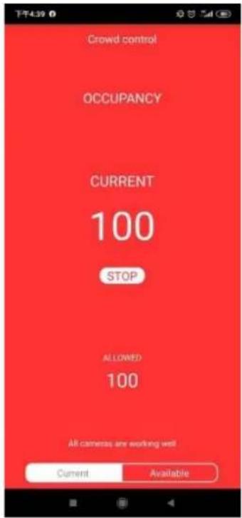
The current status will display on screen. You can constantly monitor the occupancy situation of your facility or store.

Customizable Screen Configuration:
- Enter the Social Distancing control page and click on the Settings button. Click on Appearance.
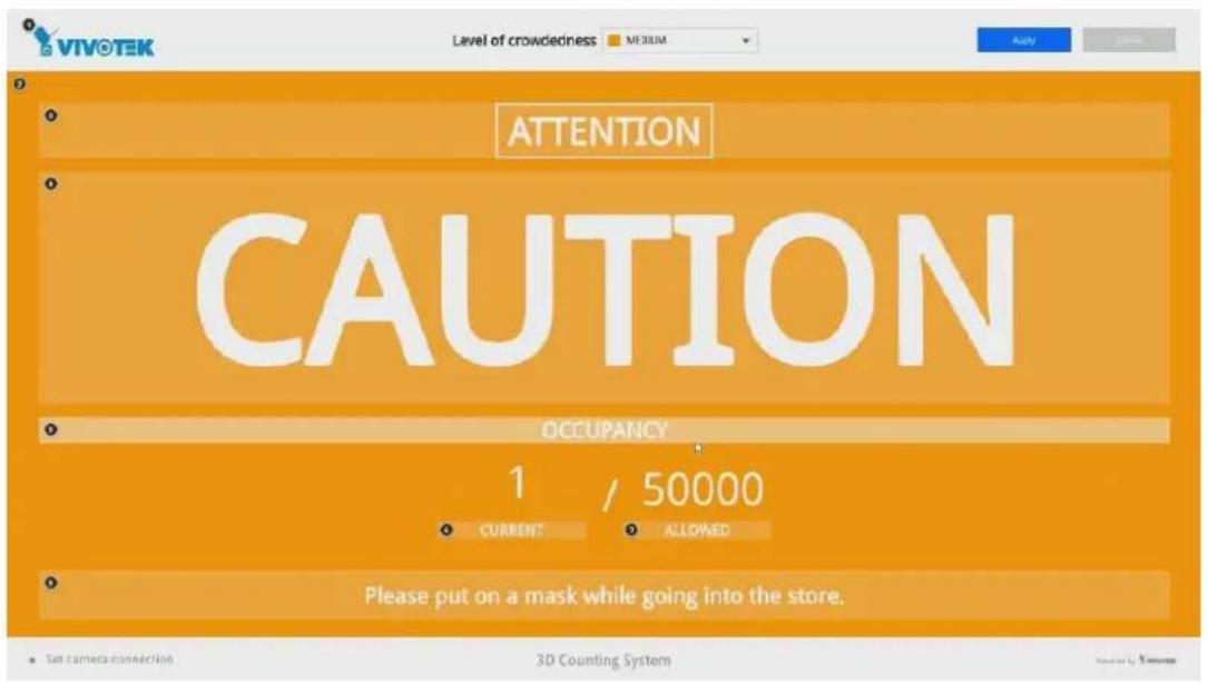
- You can customize numerous screen panes. Click on each of the color pane.
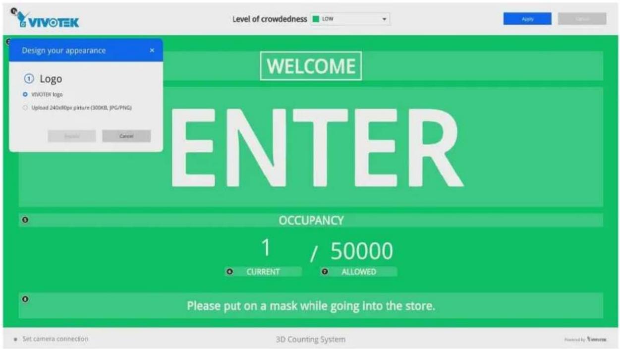
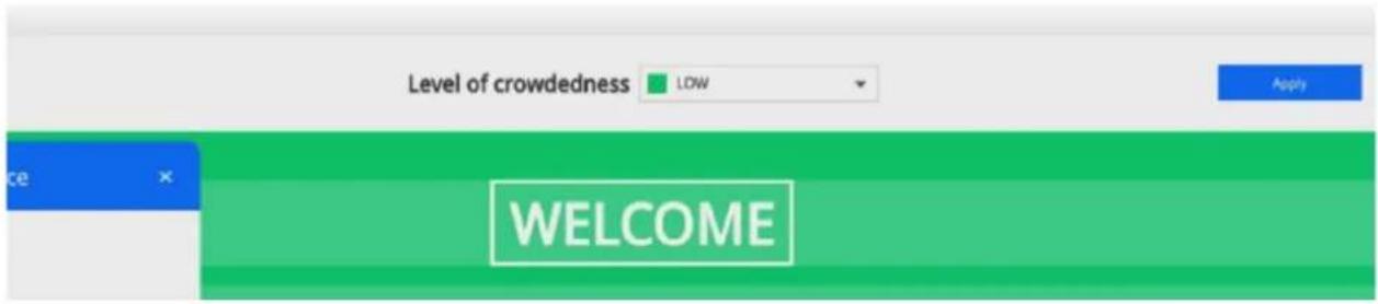
There are 3 main screens: Low, Medium, and High. Select the screen for the Level of crowdedness, and then configure your screen.
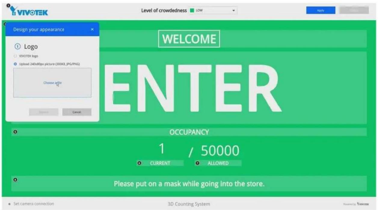
- You can refer to the image size information, e.g., that for your company's logo. Prepare the image files and save them to a USB thumb drive.
It is recommended you jot down the sizes of every screen panes, prepare the image files and upload.
| Pane | Image size | Pane | Image size |
| Logo | 240x80 pxl | Occupancy | 1820x40 pxl |
| Background color | 1920x910 pxl | Current occupancy | 240x30 pxl |
| Hint | 1820x90 pxl | Allowed occupancy | 240x30 pxl |
| Action | 1820x375 pxl | Information | 1820x80 pxl |
- You can change the screen information by entering a string of your preference, such as, "Masking is mandatory!"
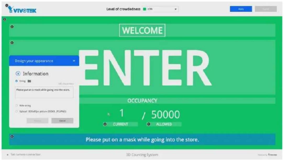
Note that you will need 3 sets of image combinations for 3 levels of occupancy.
- When done with configuring all screen panes, click the Apply button on the upper-right of your screen.
Section One: Management over a Local Console
Chapter 2: Introduction to the Local Console Interface
natural_image
Diagram of a computer monitor with ports and accessories (no text or symbols)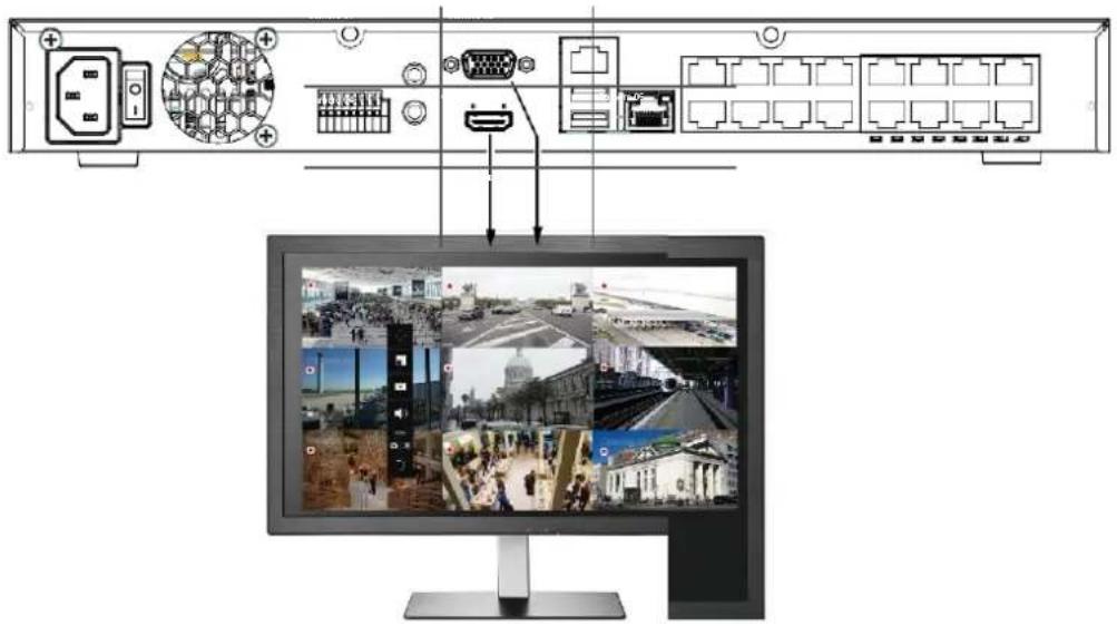
By default, a live view appears on an HDMI monitor. The interface architecture of the local console is illustrated as follows:
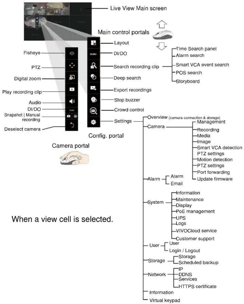
flowchart
graph TD
    A["Live View Main screen"] --> B["Main control portals"]
    B --> C["Fisheye"]
    B --> D["PTZ"]
    B --> E["Digital zoom"]
    B --> F["Play recording clip"]
    B --> G["Audio"]
    B --> H["DI/DO"]
    B --> I["Snapshot | Manual recording"]
    B --> J["Deselect camera"]
    B --> K["Layout"]
    K --> L["DI/DO"]
    K --> M["Search recording clip"]
    K --> N["Deep search"]
    K --> O["Export recordings"]
    K --> P["Stop buzzer"]
    K --> Q["Crowd control"]
    K --> R["Settings"]
    R --> S["Camera portal"]
    S --> T["Overview (camera connection & storage)"]
    S --> U["Camera"]
    U --> V["Management"]
    U --> W["Recording"]
    U --> X["Media"]
    U --> Y["Image"]
    U --> Z["Smart VCA detection PTZ settings"]
    U --> AA["Motion detection"]
    U --> AB["PTZ settings"]
    U --> AC["Port forwarding"]
    U --> AD["Update firmware"]
    S --> AE["Alarm"]
    AE --> AF["Alarm Email"]
    S --> AG["System"]
    AG --> AH["Information Maintenance Display PoE management UPS Logs VIVOCloud service Customer support"]
    AG --> AI["User Login / Logout Storage Scheduled backup"]
    AG --> AJ["Storage IP DDNS Services HTTPS certificate"]
    AG --> AK["Information Virtual keypad"]
After you finish configuring using a Camera portal, click again on the camera view cell to reveal the main control portals.
For the Export recordings function, refer to page 85.
2-1. How to Begin
1. How to access the Configuration Portal?
Make sure a mouse is attached to your NVR. Move your mouse cursor, and the Configuration Portal will appear on screen. For all the configurable options available through this portal, please refer to Chapter 3 on page 61.

You can also hide these portal toolbar. Right-click on the Live View screen to display the option.
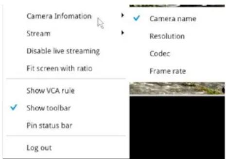
2. How to access the Camera Portal?
Single click to select a view cell, the Camera Portal will appear. The system automatically detects the characteristics of an individual camera when you select a view cell.

This portal appears with a camera that supports mechanical PTZ.
This portal appears with a camera that does not support mechanical PTZ.


Tips:
Here are some operation steps using the tool bar:
- Single-click to select a view cell and bring out the tool bar.
- Double-click to expand a view cell to the full view.
- Double-click again to shrink the view cell to the original size.
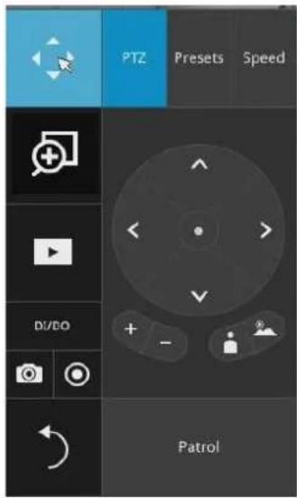
PTZ control panel for ordinary PTZ type
PTZ control panel for joystick type PTZ
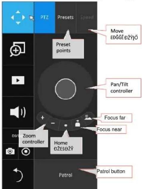
PTZ presets: If your PTZ cameras have preset locations, click on the button to unfold the preset menu. Click on any of the preset locations to move to the area of your interest.
Pan/Tilt controller: Pull the inner circle to the direction you prefer. Release the mouse button to stop moving.
Zoom controller: The zoom controller buttons only apply to cameras that come with an optical zoom module, such as a speed dome camera.
Focus controller: The focus controller buttons apply to cameras that come with focus control over its lens module, such as a speed dome camera.
3. How to retrieve and access recorded videos?
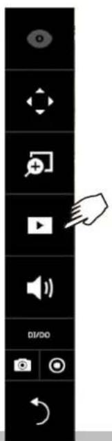
3-1. One is to access the video clips taken within 2 hours. Left click to select a view cell, and then click on the Recording clips button.
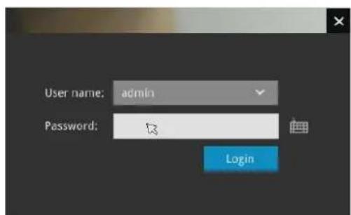
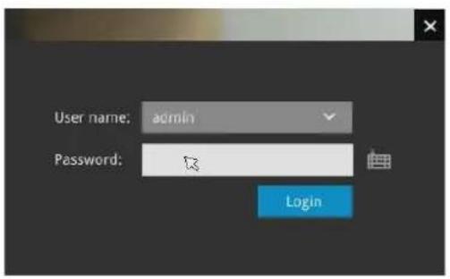
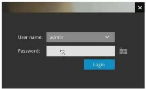
Select a time value by a single click. You will be prompted for Username and Password, enter admin and admin (the default user name and password), and then click Login.
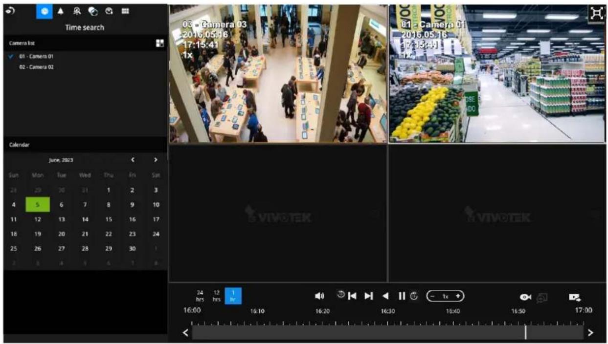
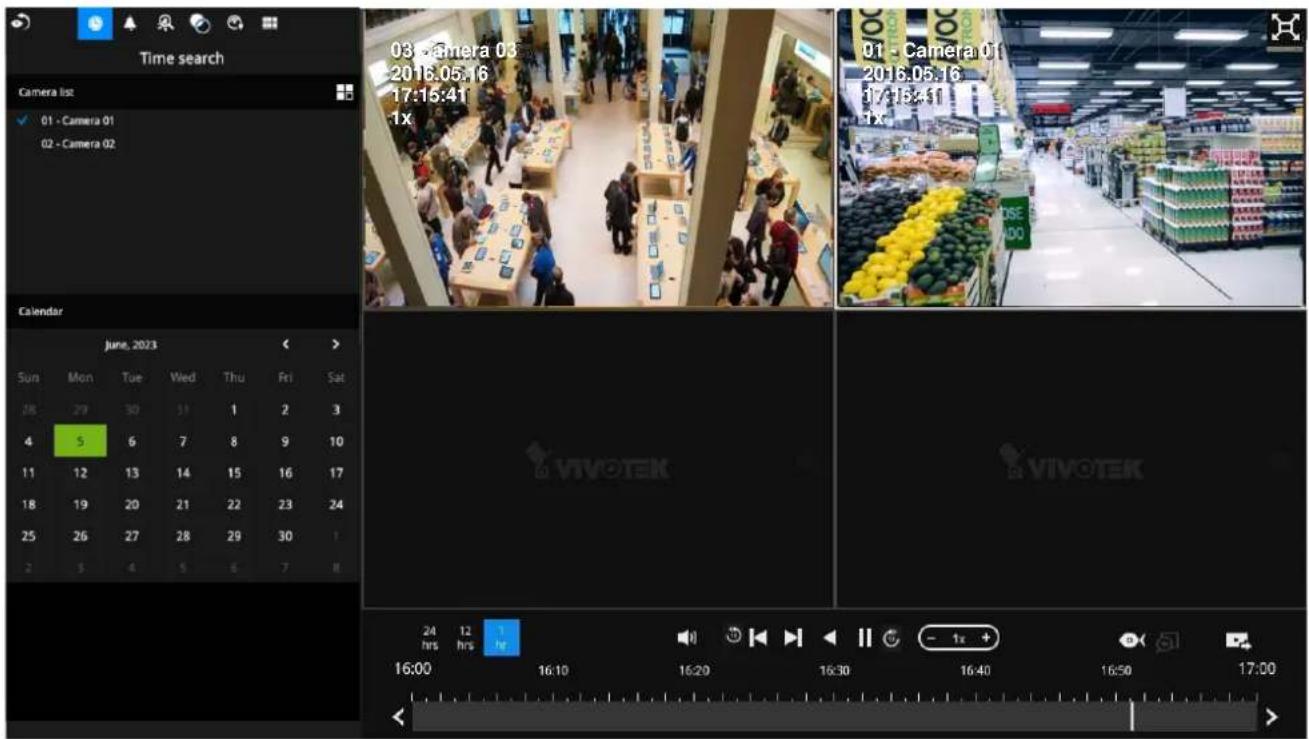
The Playback window will prompt, and a playback begins from the point in time you selected, e.g., 30 seconds ago. This function allows you to quickly review what has just happened.
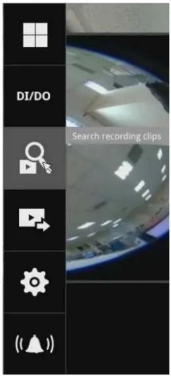
3-2. Another way to access past videos is to open the Search recording clips window. Move your mouse cursor to display the Configuration Portal (without selecting any view cell). Click on the Search recording clips button. Please refer to page 62 for more information about the search functions.
You will be prompted for Username and Password, enter admin and admin (the default username and password) and click Login.
It is highly recommended to change the password after you log in.
4. How to receive system alarm?
Please refer to page 118 for how to configure system alarm triggers. When the alarm is triggered, e.g., by digital inputs or motion detection, an alarm message will prompt on the screen.
Use the > arrow button to browse through the alarm messages.
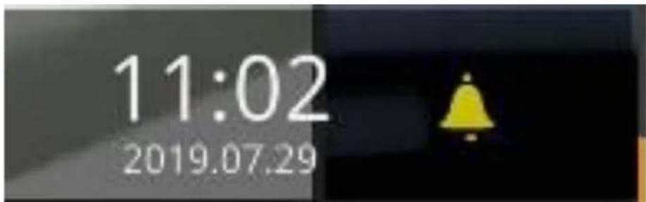
If the alarm is configured with video recording as the responding action, you can click on the alarm entry. The Playback window will appear, allowing an instant playback of the alarm-related footage. You will enter the "Search alarm results" page even if the alarm does not trigger a recording action.
5. Why live view is unavailable?
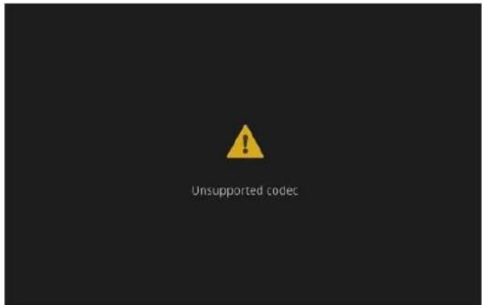
The default live view receives a camera's stream #1. If a camera's stream #1 is configured using MPEG-4 as the video codec, the following message will prompt.
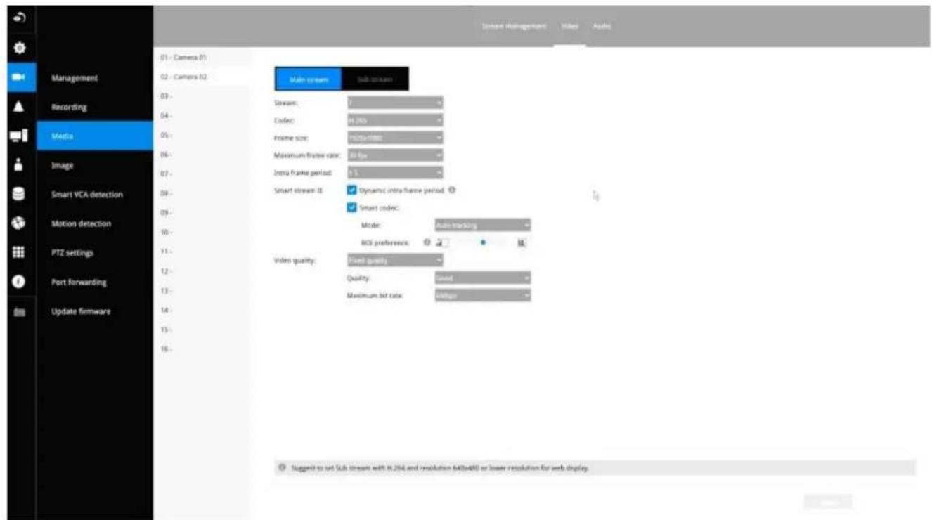
You can go to the Settings > Camera > Media > Video window to configure the video codec of stream #1 into H.264 or H.265.
6. How do I move to another layout page?
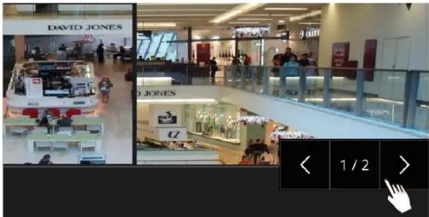
Move your cursor to the right-hand side of your screen. The page turner buttons will appear as shown below.
For example, if you have 8 cameras placed on 2 2x2 layout pages, use these buttons to visit different pages.
7. Why the onscreen tool bars disappear after some time?
The system comes with idle modes. Below are the applicable conditions:
- Live view: if no management activities occur for 5 seconds, the tool bars disappear from screen. When in the idle mode, mouse cursor and tool bars will disappear. Moving the mouse cursor will re-activate the screen.
- Settings page: If left unattended for 10 minutes, the system will automatically log out. The system will prompt for user credentials if a user tries to access the Settings page again.
- Search recording clips window: If currently there is a video playback, the system will not enter the idle mode.
2-2. Operation on Camera View Cell
2-2-1. PTZ Panel

Once you selected a camera, click on the PTZ button on a camera portal.
The PTZ panel will prompt. Below is the description of its functions:
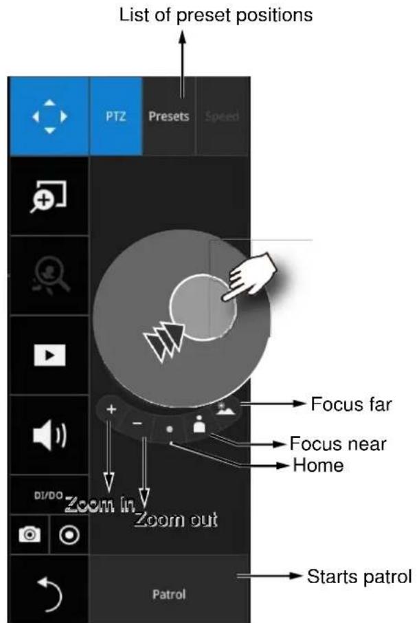
- PTZ control: Click and drag the nudge in the center towards the direction you wish to move to.
- Focus: Click on the Focus near and Focus far buttons to adjust camera focus.
- Home: Click to move the camera lens towards the default home position.
- Zoom: Use the Zoom in and Zoom out buttons to adjust the camera's zoom ratio.
- Presets: If you configured preset positions, a list of preset positions will appear.
- Patrol: If you configured preset positions into a patrolling tour, click on this button and the camera will proceed with patrolling through preset points.
Note that on a speed dome camera, the farther you pull the nudge away from the center, the faster the lens moves. This works like speed control.
Below is the PTZ panel that appears with ordinary PTZ cameras.
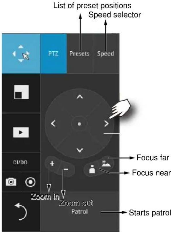
- PTZ control: Click on the arrow buttons to move towards the direction you wish to move to.
- Focus: Click on the Focus near and Focus far buttons to adjust camera focus.
- Zoom: Use the Zoom in and Zoom out buttons to adjust the camera's zoom ratio.
- Presets: If you configured preset positions, a list of preset positions will appear.
- Speed: Adjusts the speed when moving across the field of view.
- Patrol: If you configured preset positions into a patrolling tour, click on this button and the camera will proceed with patrolling through the preset points.

IMPORTANT:
Due to the limitation of system resources, the fisheye dewarp (1R & 1P) can only take place on one view cell, for one fisheye camera.
Currently the fisheye dewarp function takes place on a web console.
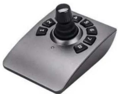
Joystick support
natural_image
Silver remote control console with black rotary knob and control buttons (no text or symbols visible)The joystick related operations are listed below:
- Pan: Continuous move is supported. (joystick X-axis movement)
- Tilt: Continuous move is supported. (joystick Y-axis movement)
- Zoom: Continuous move is supported. To zoom in, move joystick Z-axis clockwise (or use button #2). To zoom out, move joystick Z-axis counter-clockwise (or use button #3)
- Home: joystick button #1.
- Auto Pan: joystick button #5.
- Patrol: joystick button #7. Preset positions must be pre-configured for the camera.
- Stop: Stops auto pan or patrol. Joystick button #6.
2-2-2. Digital zoom Panel

Digital zoom is a function that provides digital zoom into a live video. Be sure you place your mouse cursor inside the Global view window for the zoom function to take effect.
When activated, a Global view window will appear at the lower right of the view cell as shown below. You can display only a portion of the complete video frame as an area of your interest. Using a click and drag on the ROI window, you can instantly move to other areas within the video frame. Use the zoom ratio pull bar at the bottom to change the zoom ratio. You may also move the ROI around by click and drags.
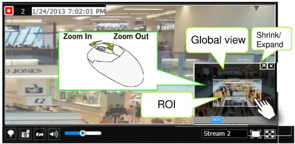
Note that not every camera supports the PiP function.
2-2-3. Play Recording Clips Panel

The Play Recording Clips function provides a shortcut to the latest recordings on the system. You can select 30 secs, 1 min, 3 mins, 10 mins, and 60 mins for an immediate playback.
For security reasons, using this function requires users to enter his/her credentials.
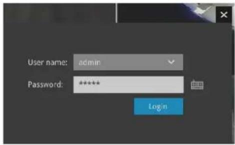
The Playback window will prompt, and a playback begins from the point in time you selected, e.g., 30 seconds ago. This function allows you to quickly review what has just happened.
2-2-4. DI/DO
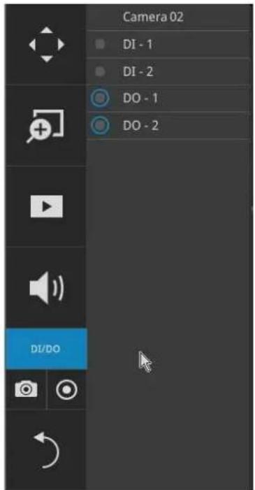
The DI/DO panel provides a glimpse of all DI and DO signal statuses from the connected cameras. You can manually trigger a digital output by clicking on its indicators.
When a digital input is triggered, its status will also be indicated on the panel.

WARNING:
Please note that DO is triggered by one click. You should then click again to disable the DO. Otherwise, the DO signal will be continuously triggered. As the result, if the DO is configured as an alarm trigger, many alarm messages will be generated.
2-2-5. Others
- Snapshot ☐: is used to take a snapshot from the camera currently selected. Note that this function only saves the snapshot (in JPEG) to a USB thumb drive.

IMPPORTANT:
The USB thumb drive has to be one that is formatted in FAT format.
- Manual Recording ☐: Press the button to start a manual recording from a selected camera. Click again to stop the recording.
- Return button ↗ : Click to return to the Live View


2-2-6. Right-click Commands
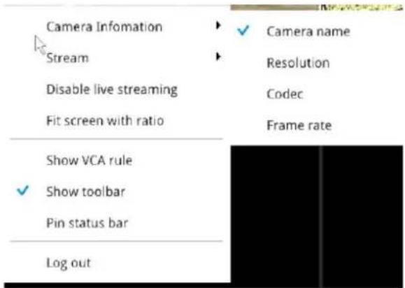
Left-click to select a camera. Right-click to display the selection menu.
- Camera information: Click to display camera name, resolution, codec, or frame rate on the view cell. The information will display on the upper left corner of a view cell.
- Stream: Select to display the main or subordinate stream.
- Disable live streaming: Choose to display snapshots on the screen instead. The snapshots are regularly replaced.
- Fit screen with ratio: The NVR server automatically optimizes the display of camera view cells. However, you can still select this option to display the camera's original aspect ratio: for example, the original video feed can be 4:3. Without the fit screen, every camera's image will be expanded to fill the view cell.
- Show tool bar: You can hide the tool bars by deselecting this option.
- Pin status bar: If selected, the status bar will constantly display on screen.
- Log in/Log out: Log in to enable system configuration.
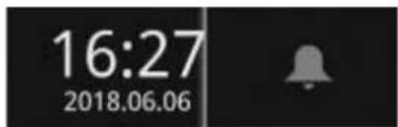
A time tab is displayed at the lower center of the screen. You can move your cursor to the lower center to display the time tab and the alarm panel.
For the 3D counting cameras, right-click on its view cell to display the counting rule option. You can enable the display of counting lines, and the bounding boxes for detected objects. The counting results are acquired through the VIVOCloud utility.
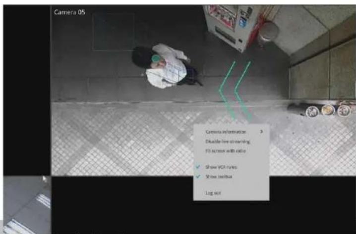
Note that the NVR supports the connection of up to 4 counting cameras. The VCA rule displays only on the 2x2 layout.
Chapter 3: Configuration Using the Local Console
The Main Control Portal
3-1. Layout
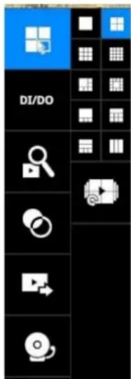
Move your mouse cursor across the screen to display the portal.
The local layouts:
ND9326P: 1x1, 2x2, 3x3, 1M+5, 1P+3, 1P+6, 2P+3, 3V
ND9426P: 1x1, 2x2, 3x3, 4X4, 1M+5, 1M+7, 1M+12, 1P+3, 1P+6, 2P+3, 2V+3,
1V+6, 3V
If you select the single view layout, the rotation button

will appear. Click the
rotation button below to let the system swap the display of different cameras by every 10 seconds. The rotation speed is configurable via Settings > System > Display.
3-2. DI/DO
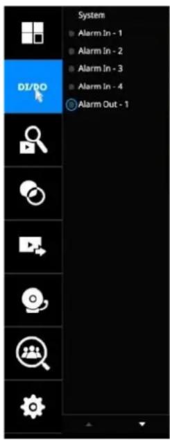
Click on the DI/DO button to display the full list of all DI and DO signals (whether they are connected or not) from all cameras in the configuration. If a digital input signal is triggered, e.g., the DI-4 on the left, its indicator will turn solid white.
Note that you should click again to disable a DO after it is triggered. Otherwise, the DO will be constantly triggered.
3-3. Search recording clips
3-3-1. Basic Search

Click the button to start searching for recorded clips. A confirm box will prompt. Enter User name and Password to proceed.
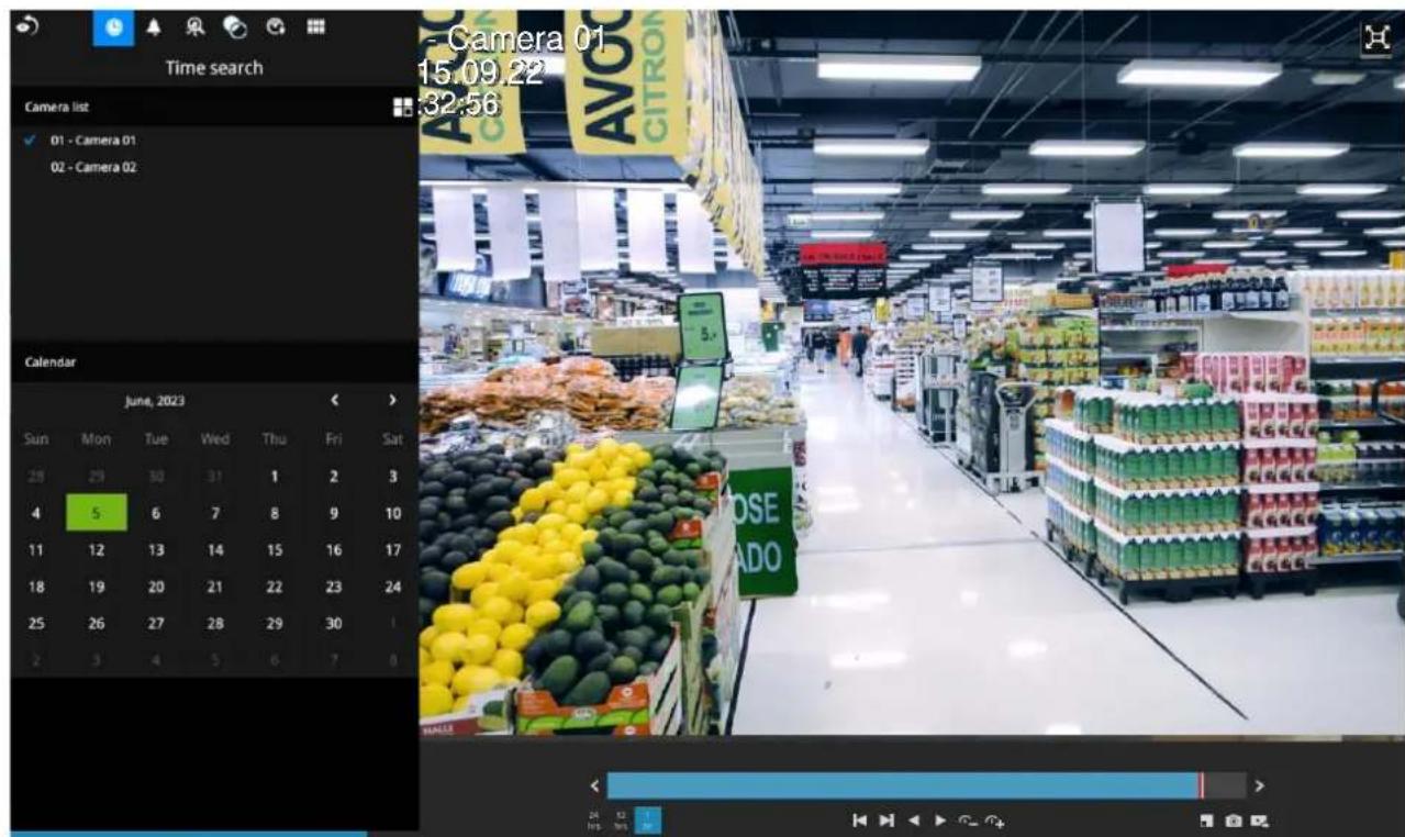
The search and calendar view will appear. Select a day on the calendar to select the date when the recordings of your interest took place (the days with recorded clips will be highlighted in blue and green).
Double-click on a day to begin playback and search.
The date highlighted in green indicates today, and the green indicator does not necessarily mean that there are recorded videos today.
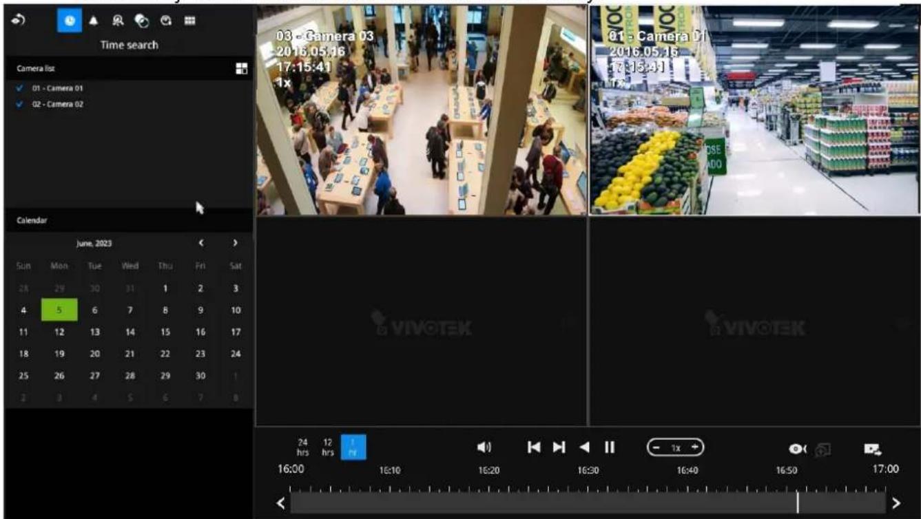
Use the layout button to adjust view cell arrangement on screen. You can retrieve the recorded videos from a max. of 4 cameras at the same time.
Once you select to playback multiple cameras, the playback window will automatically turn into the 2x2 layout. Up to 4 cameras' recording can be played back simultaneously. This enables the synchronized playback of video produced by multiple cameras. Users do not need to switch from one camera to another when searching for forensic evidences.
The timeline bar enables quick skimming through the recording. Its functions are described as follows:
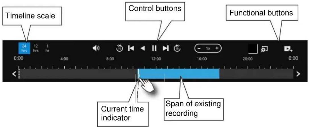
| Buttons | Description | |
 | Time scale selector. Use the buttons to select the span of time displayed on the tool bar. | |
 | Audio volume tuner. | |
 | Plays back from 10 seconds ago. | |
 | Previous frame. (I-frame only) | |
 | Next frame. (I-frame only) After you paused a playback, use this button to browse video frame by frame. | |
 | Play backwards. | |
 | Play. This button is available after you paused a playback. | |
| [542T] | Pause. | |
 | Each click on it speeds down by 1/2. The slowest speed is 1/16. | |
 | Each click on it speeds up by 2x. The fastest speed is 16 times. The current playback status is indicated on the screen. | |
 | This button appears when you select to playback a fisheye camera's recording. This avails the selection of dewarp modes usable during the playback. | |
 | Digital zoom. This applies when a camera is displaying the full of its field of view. You can use the Digital zoom function to zoom in on the field of view. | |
 | Export clips. Use this function to select a span of time you want to export to other medias. | |
By default, the playback starts from the beginning of a day's recording. While playing the recorded video, click on the timeline to replay a point in time in the video.

Snapshot. Takes a snapshot of the current FOV. The Snapshot button has been moved to the right-hand side of each view cell.

The fisheye dewarp modes can be selected during a playback: e.g., 1R, 1P, 1O3R, or 1O8R.
When playing the video recorded by a fisheye camera, the fisheye display options will be available on screen. You can click to select the 1O, 1P (Panoramic), 1R (Regional), or 1O3R (1 Original and 3 Regional), or 1O8R modes. If 1P, 1R, 1O3R, or 1O8R mode is selected, you can exert the mouse control on screen, such as swiping the view, or hold down the mouse button and swipe the field of view.
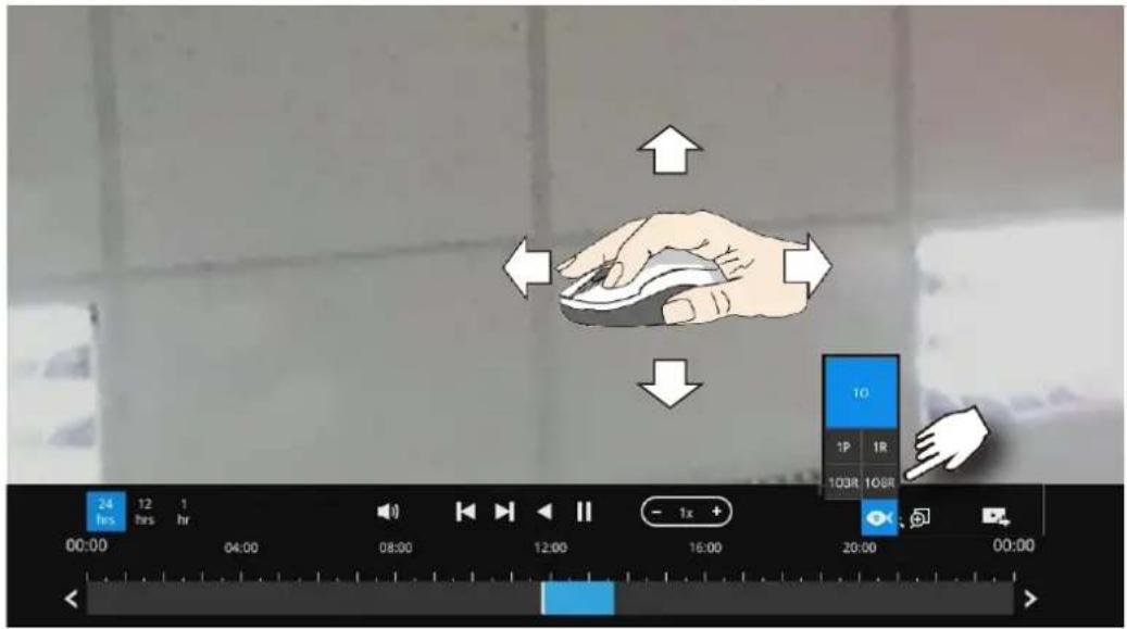
Please refer to the User Manuals that came with fisheye cameras, or page 168 for description of fisheye display modes.
Note that to export a video segment from the playback timeline,

- Click on the Export button
- Insert a USB drive formatted in the FAT format.
- Select the "From time" by clicking on the timeline. You can also manually enter the "From time" and the "To time."
- Click on the "From time" tab using a single click.
- Repeat steps 3 and 4 to configure the To time.
- Click on the Export button.
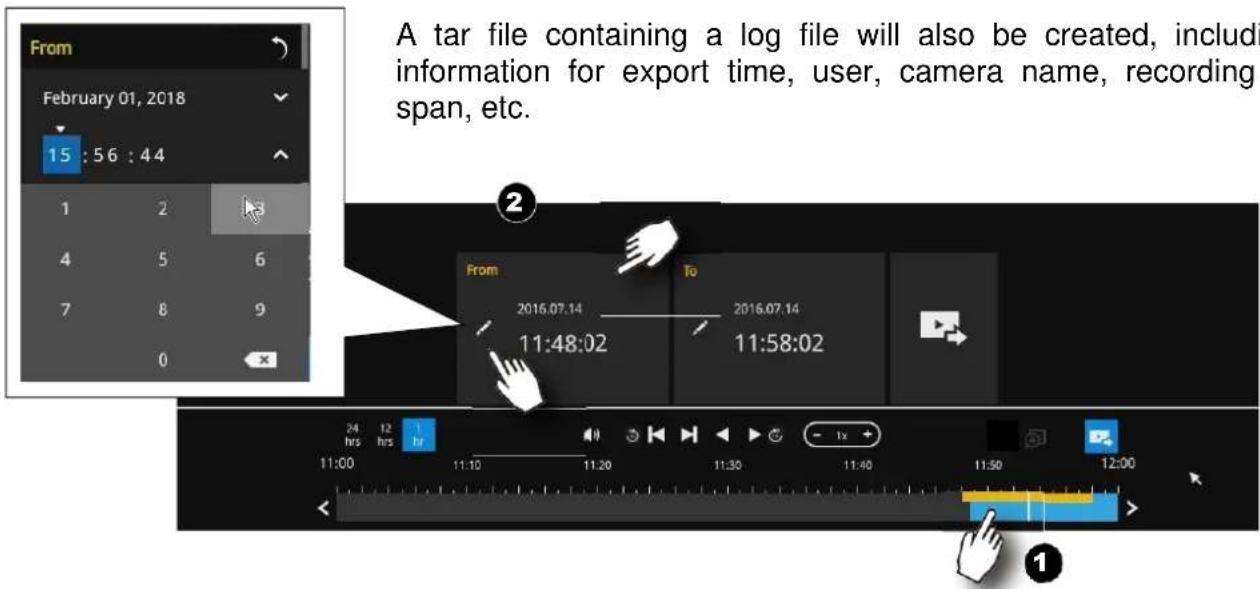
A tar file containing a log file will also be created, including the information for export time, user, camera name, recording time span, etc.
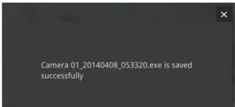
The export process is indicated on the right. Depending on the length of footage to be exported, this process can take minutes.

When completed, a message will display on screen.
The default for export is 5 minutes before and 5 minutes after the point in time that is currently selected.
3-3-2. Alarm Search
Click on the Alarm search button on the upper left of the screen to enter the Alarm Search panel.
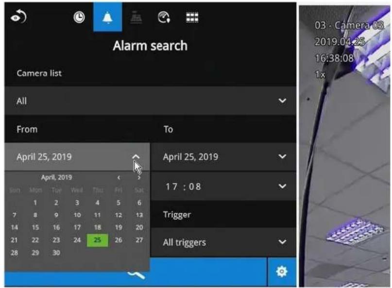
You can specify the search criteria by selecting the devices to be involved in the Alarm search.
- Camera list.
- The From and To time.
- Pre-configured alarms, such as those associated with camera DI, motion detection, or VCA analytics triggers, etc.
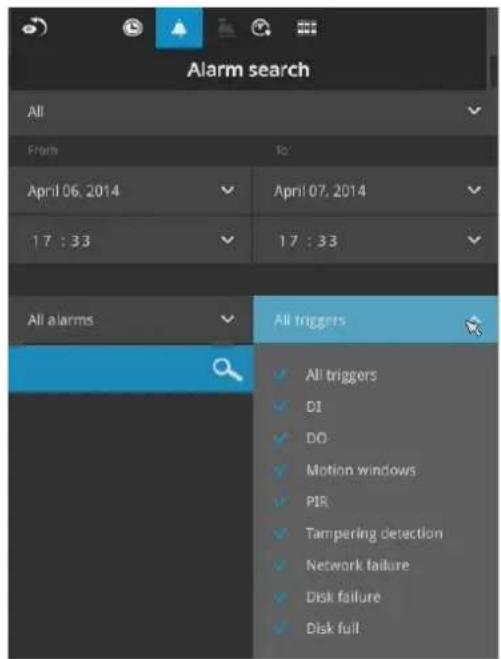
- Trigger: DI, DO, tampering detection, disk failure, cyber security events, and VCA video analytics events.
Use the combinations of these parameters to sort through the alarms.
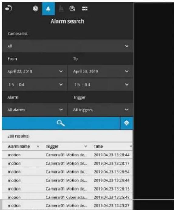
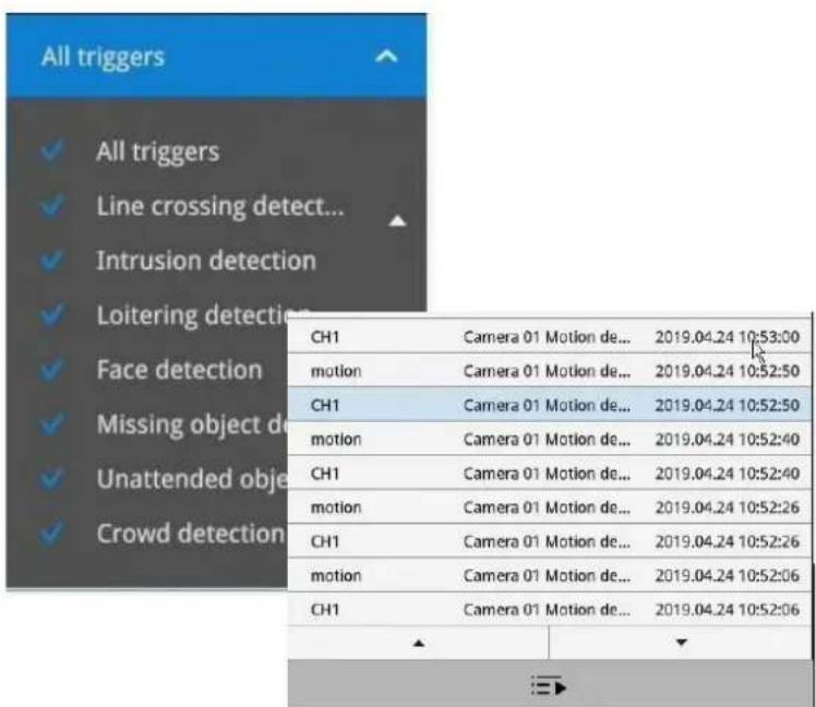
66 - User's Manual
You can then specify the start time and end time to configure a span of time to be searched.
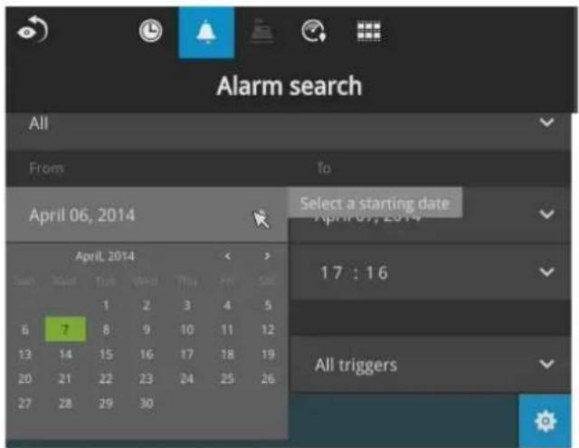
You can also determine what alarms will be included in the search.
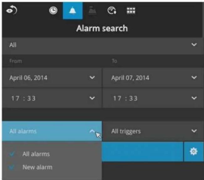
You can select what types of triggers were associated with the recordings you want to find.
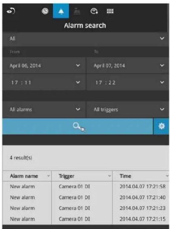
When done with the selection, click on the Search button. In the sample screen below, a list of alarms is displayed, and you can click on any of them to replay the moment when the alarm was triggered. The alarm-related recording will typically include a length of 5 seconds of pre-alarm and 20 seconds of post-alarm footage.
Up to 200 search result entries will appear. If more than 200 entries have been found, click on the New results button on the last entry page.
If two cameras participate in the recording of an alarm-related event, the footage of one camera will be played first, and then that of the other.
If a user's operation takes place (pause, rewind, etc.) during the playback, the system will stop the consecutive playback of multiple alarm footages.

NOTE:
When the Search window is left unattended for 10 minutes, the NVR will return to the live view display. To enter the Search window, you will have to enter the user credentials again.
Use the page up and page down buttons to browse through the alarm list. Use the continuous playback button to let the system automatically play all alarm clips. The continuous play starts from the first alarm or from the alarm you currently clicked and selected. Click on the button again to stop the continuous play.
| CH1 | Camera 01 Motion de... | 2019.04.24 10:53:00 |
| motion | Camera 01 Motion de... | 2019.04.24 10:52:50 |
| CH1 | Camera 01 Motion de... | 2019.04.24 10:52:50 |
| motion | Camera 01 Motion de... | 2019.04.24 10:52:40 |
| CH1 | Camera 01 Motion de... | 2019.04.24 10:52:40 |
| motion | Camera 01 Motion de... | 2019.04.24 10:52:26 |
| CH1 | Camera 01 Motion de... | 2019.04.24 10:52:26 |
| motion | Camera 01 Motion de... | 2019.04.24 10:52:06 |
| CH1 | Camera 01 Motion de... | 2019.04.24 10:52:06 |

NOTE:
When the Search window is left unattended for 10 minutes, the NVR will return to the live view display. To enter the Search window, you will have to enter the user credentials again.
3-3. Search recording clips
3-3-1. Basic Search
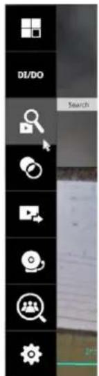
Click the button to start searching for recorded clips. A confirm box will prompt. Enter Username and Password to proceed.
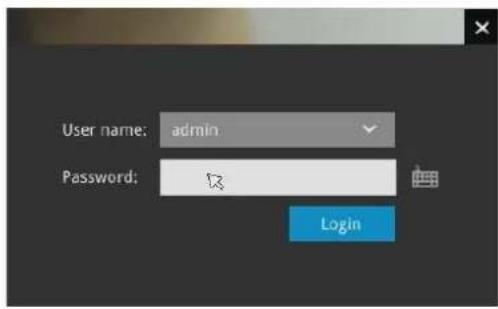
The search and calendar view will appear. Select a day on the calendar to select the date when the recordings of your interest took place (the days with recorded clips will be highlighted in blue and green).
Double-click on a day to begin playback and search.
The date highlighted in green indicates today, and the green indicator does not necessarily mean that there are recorded videos today.
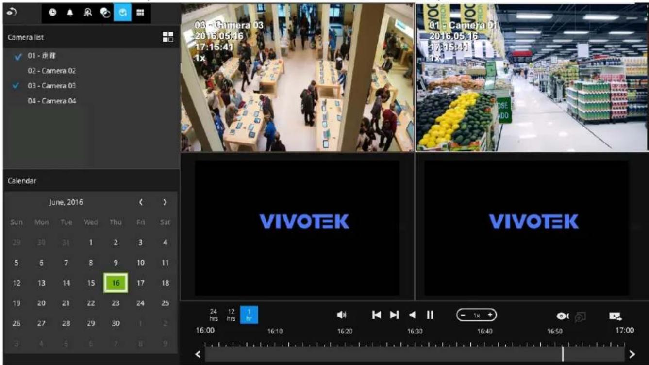
Use the layout button 📋 to adjust view cell arrangement on screen. You can retrieve the recorded videos from a max. of 4 cameras at the same time.
Once you select to playback multiple cameras, the playback window will automatically turn into the 2x2 layout. Up to 4 cameras' recording can be played back simultaneously. This enables the synchronized playback of video produced by multiple cameras. Users do not need to switch from one camera to another when searching for forensic evidence.
The timeline bar enables quick skimming through the recording. Its functions are described as follows:
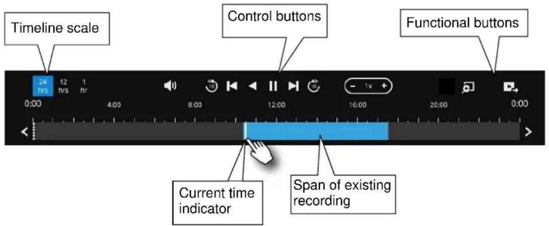
| Buttons | Description | |
 | Time scale selector. Use the buttons to select the span of time displayed on the tool bar. | |
 | Audio volume tuner. | |
 | Plays back from 10 seconds ago. | |
 | Previous frame. (I-frame only) | |
 | Next frame. (I-frame only) After you paused a playback, use this button to browse video frame by frame. | |
 | Play backwards. | |
 | Play. This button is available after you paused a playback. | |
 | Pause. | |
 | Each click on it speeds down by 1/2. The slowest speed is 1/16. | |
 | Each click on it speeds up by 2x. The fastest speed is 16 times. The current playback status is indicated on the screen. | |
 | Digital zoom. This applies when a camera is displaying the full of its field of view. You can use the Digital zoom function to zoom in on the field of view. | |
 | Export clips. Use this function to select a span of time you want to export to other medias. | |
By default, the playback starts from the beginning of a day's recording. While playing the recorded video, click on the timeline to replay a point in time in the video.

Snapshot. Takes a snapshot of the current FOV. The Snapshot button has been moved to the right-hand side of each view cell.
Note that to export a video segment from the playback timeline,

- Click on the Export button
- Insert a USB drive formatted in the FAT format.
- Select the "From time" by clicking on the timeline. You can also manually enter the "From time" and the "To time."
- Click on the "From time" tab using a single click.
- Repeat steps 3 and 4 to configure the To time.
- Click on the Export button.
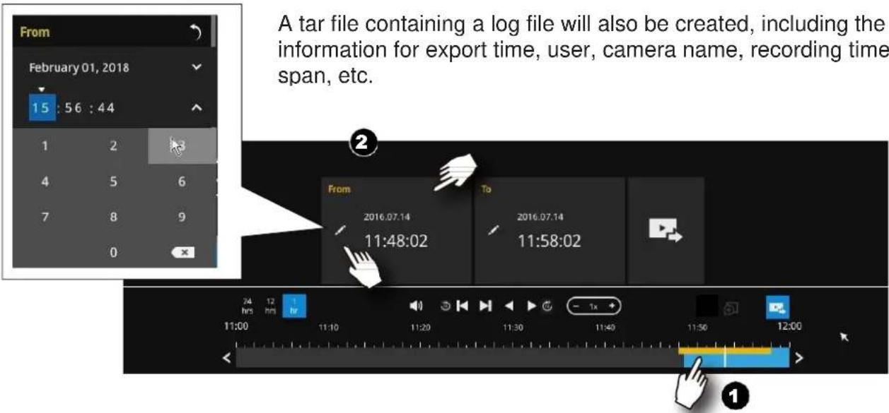
The export process is indicated on the right. Depending on the length of footage to be exported, this process can take minutes.

When completed, a message will display on screen.
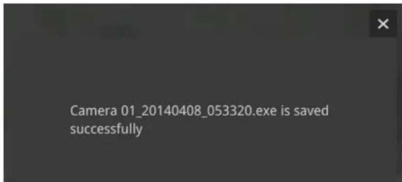
The default for export is 5 minutes before and 5 minutes after the point in time that is currently selected.
3-3-2. Alarm Search
Click on the Alarm search button 📋 on the upper left of the screen to enter the Alarm Search panel.
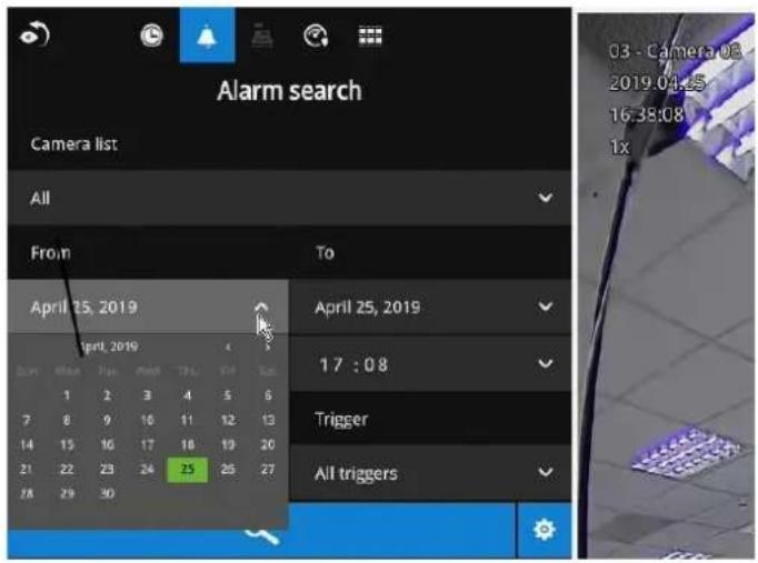
You can specify the search criteria by selecting the devices to be involved in the Alarm search.
- Camera list.
- The From and To time.
- Pre-configured alarms, such as those associated with camera DI, motion detection, or VCA analytics triggers, etc.
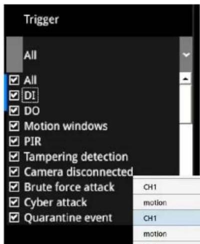
- Trigger: DI, DO, tampering detection, disk failure, cyber security events, and VCA video analytics events.
Use the combinations of these parameters to sort through the alarms.
| CH1 | Camera 01 Motion de... | 2019.04.24 10:53:00 |
| motion | Camera 01 Motion de... | 2019.04.24 10:52:50 |
| CH1 | Camera 01 Motion de... | 2019.04.24 10:52:50 |
| motion | Camera 01 Motion de... | 2019.04.24 10:52:40 |
| CH1 | Camera 01 Motion de... | 2019.04.24 10:52:40 |
| motion | Camera 01 Motion de... | 2019.04.24 10:52:26 |
| CH1 | Camera 01 Motion de... | 2019.04.24 10:52:26 |
| motion | Camera 01 Motion de... | 2019.04.24 10:52:06 |
| CH1 | Camera 01 Motion de... | 2019.04.24 10:52:06 |
You can then specify the start time and end time to configure a span of time to be searched.
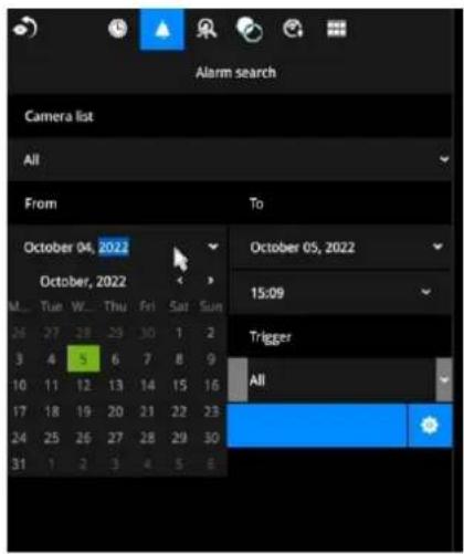
You can also determine what alarms will be included in the search.
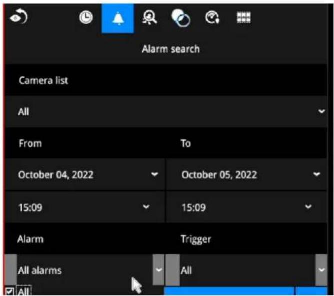
You can select what types of triggers were associated with the recordings you want to find.
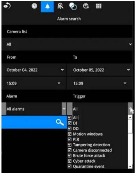
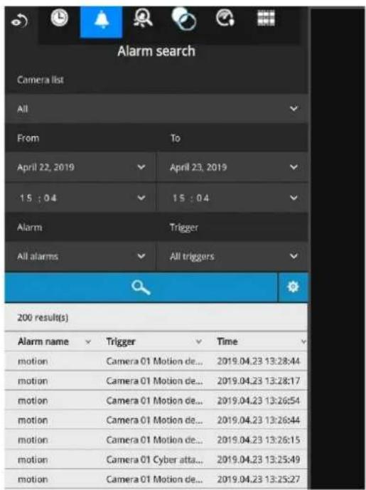
When done with the selection, click on the Search button. In the sample screen below, a list of alarms is displayed, and you can click on any of them to replay the moment when the alarm was triggered. The alarm-related recording will typically include a length of 5 seconds of pre-alarm and 20 seconds of post-alarm footage.
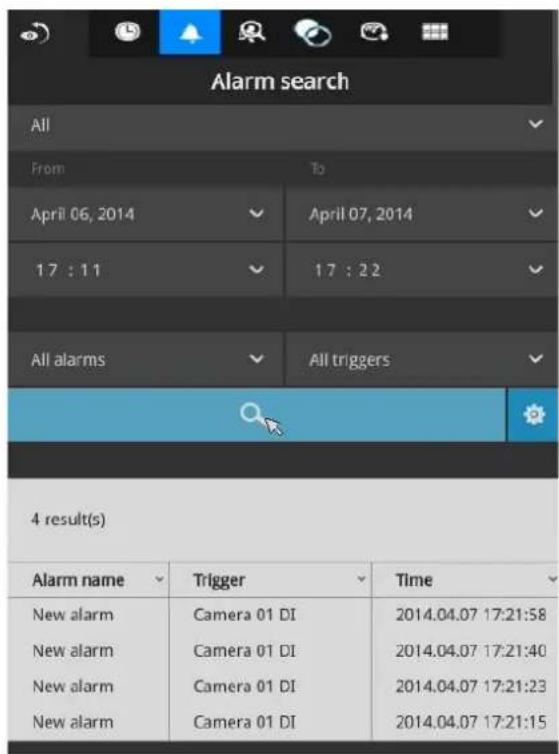
Up to 200 search result entries will appear. If more than 200 entries have been found, click on the New results button on the last entry page.
If two cameras participate in the recording of an alarm-related event, the footage of one camera will be played first, and then that of the other.
If a user's operation takes place (pause, rewind, etc.) during the playback, the system will stop the consecutive playback of multiple alarm footages.

NOTE:
When the Search window is left unattended for 10 minutes, the NVR will return to the live view display. To enter the Search window, you will have to enter the user credentials again.
Use the page up and page down buttons to browse through the alarm list. Use the continuous playback button to let the system automatically play all alarm clips. The continuous play starts from the first alarm or from the alarm you currently clicked and selected. Click on the button again to stop the continuous play.
| CH1 | Camera 01 Motion de... | 2019.04.24 10:53:00 |
| motion | Camera 01 Motion de... | 2019.04.24 10:52:50 |
| CH1 | Camera 01 Motion de... | 2019.04.24 10:52:50 |
| motion | Camera 01 Motion de... | 2019.04.24 10:52:40 |
| CH1 | Camera 01 Motion de... | 2019.04.24 10:52:40 |
| motion | Camera 01 Motion de... | 2019.04.24 10:52:26 |
| CH1 | Camera 01 Motion de... | 2019.04.24 10:52:26 |
| motion | Camera 01 Motion de... | 2019.04.24 10:52:06 |
| CH1 | Camera 01 Motion de... | 2019.04.24 10:52:06 |

NOTE:
The NVR needs to store a database on the hard drives for keeping the Deep Search metadata. Such metadata will take up storage space, yet the database size will be smaller than Smart Search II.

NOTE:
When the Search window is left unattended for 10 minutes, the NVR will return to the live view display. To enter the Search window, you will have to enter the user credentials again.
3-3-3. Smart Search II
Smart search II is available only for the newer line of cameras that come with Smart Motion detection. Smart search II has the following benefits:
- Faster search: Metadata is saved with videos coming from cameras running Smart Motion detection. With the help of the metadata, the search focuses on the effective alerted vectors and the adverse effects, e.g., headlights causing dramatic contrast or small anima3ls passing through, have already been eliminated by the camera. The search can be more rapidly completed.
- People detection: The search can be conducted for human activities only. Activities matching the silhouettes of human will be considered as effective results.
- Polygon search: Users can create a polygon on the areas of their interest to begin a search. Note that the Smart Motion detection configuration takes place on a web console to individual cameras. It is not configurable on the NVR.
Note that the Smart Motion detection areas must have been configured on each camera before the Smart search can take effect.
You can specify the time span, People detection, Sensitivity level, and time filter parameters in a Smart Search II panel.
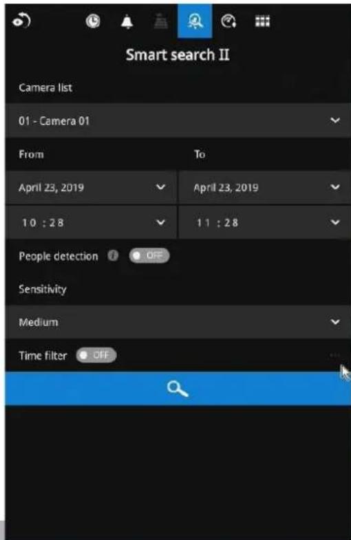
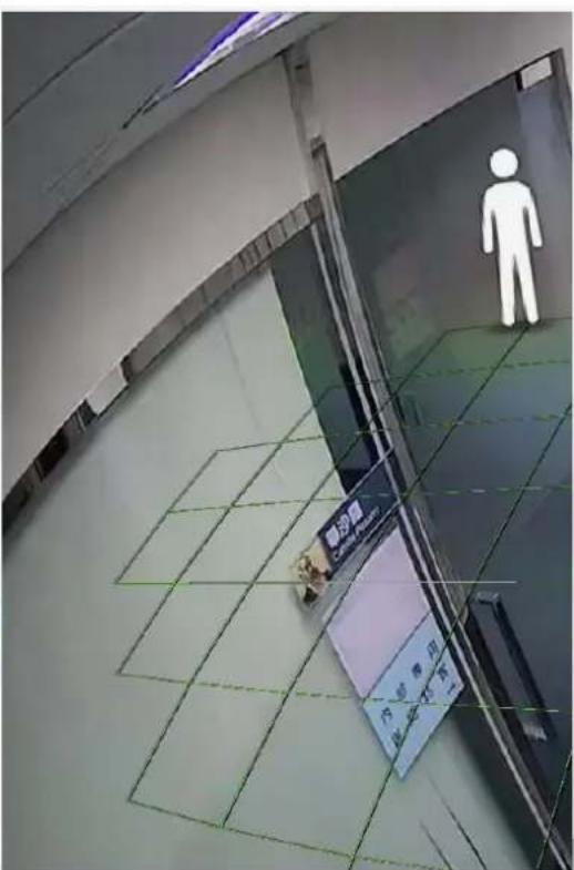
Click the Search button to begin the search. Depending on the scale of the search (how many cameras involved, and the span of recordings in search), the search should be completed in a few minutes.
The search results will display as thumbnail images. To view each short video clip, click on the thumbnail. You can also select to display the results in a list view.
You can then click to open any clip of your interest. Each marked event clip will be indicated by a lighter color on the timeline. You may then select clips of your interest and click the "Select clips to export" button. The associated clips can be exported to a USB thumb drive.
The playback video window is located on the right. Click on the Expand/Shrink button to watch the video in a full screen.
You can use the Esc button to leave the full screen. Click to select another thumbnail, or use the < or > buttons to view the previous or successive clips.
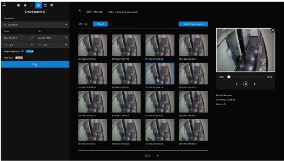
If you find important events, use the Export function to mark the start and end points on the timeline to export a video clip. By default, the export length varies depending on the appearance of moving objects.
Instead of the thumbnail view, you can also change the display of search results using the list view.
Note that when exporting video clips, each clip is selected using a small checkbox on the upper left corner of the thumbnail.
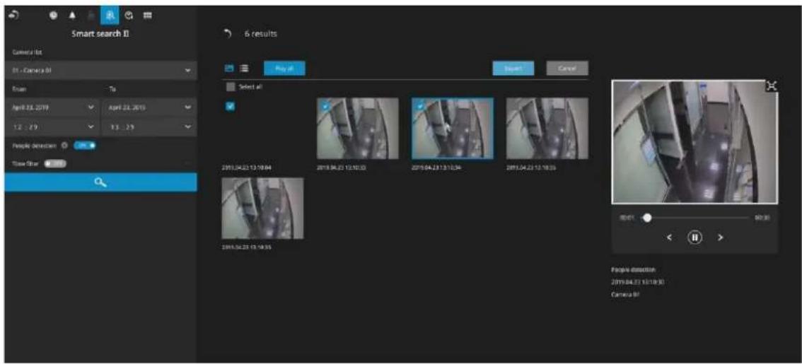
3-3-4. Deep Search
The Deep Search function uses AI empowered by VIVOTEK AI cameras to improve search functionality, and it comprises two main functions: Attribute Search and Scene Search.
Without relying on scrolling through the video footage frame by frame, VIVOTEK AI cameras provide object-based metadata to enable intelligent video evidence search.
By utilizing object-based metadata-defined attributes and rules, Deep Search helps users search for the target of interest smarter and faster.
To use the Deep Search function, make sure you have added the cameras that support Deep Search and have the time synchronizing among NVR and cameras.
NOTE:
Deep Search in firmware 4.2 or newer supports some premium and mid-range camera models. Please visit VIVOTEK's website for details of the supported cameras.
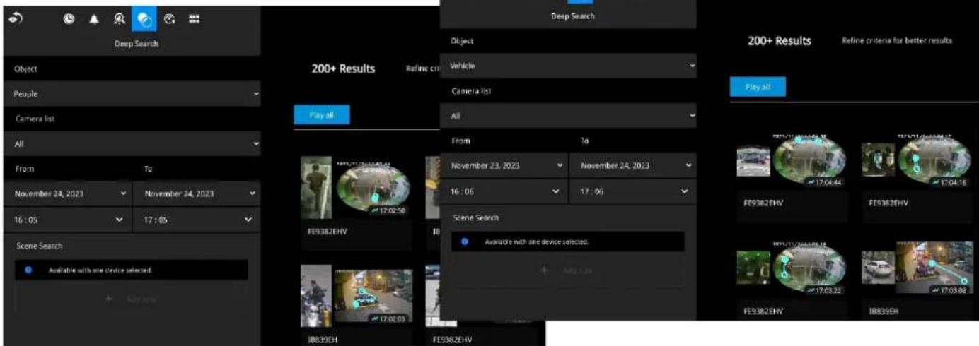
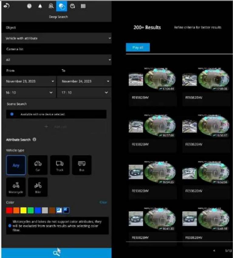
The Deep Search panel defaults to the display of all cameras and the search for People. You can select Vehicle from the pull-down menu. You should narrow down your search by clicking on the Search in column.
NOTE:
Deep Search can be accessed only through the NVR local UI.
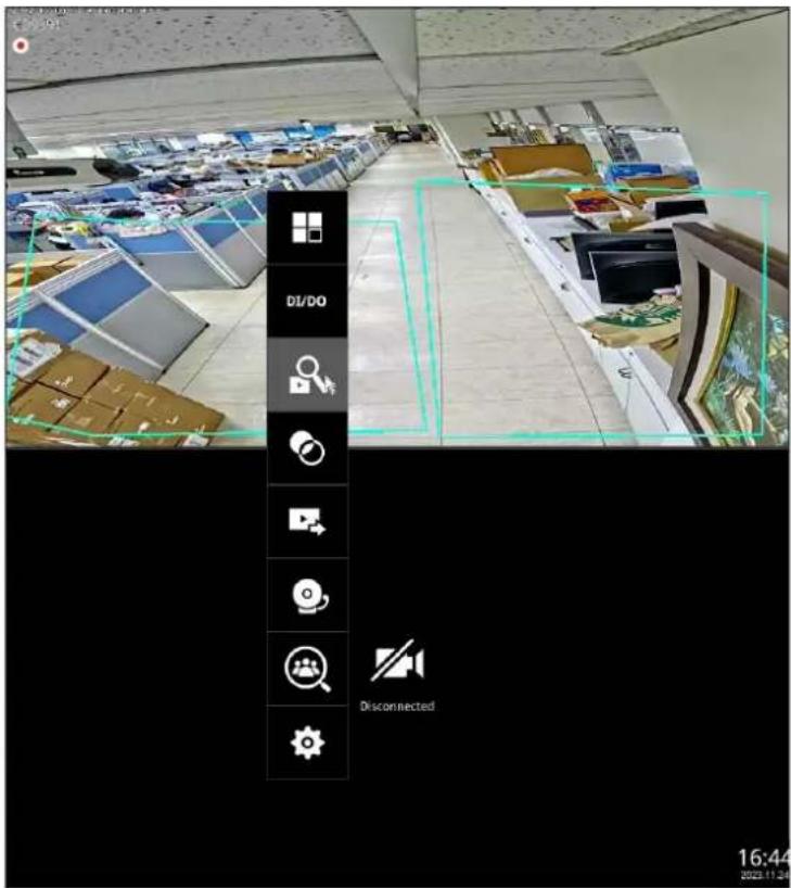
To activate Deep Search, click on the Deep Search icon in the toolbar of the NVR live view cell.
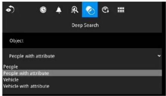
Select one of the following object types from the pull-down menu:
- People
• People with attribute - Vehicle
• Vehicle with attribute.
Select "People" or "Vehicle" objects if you want to search for people or vehicles in a recorded video.
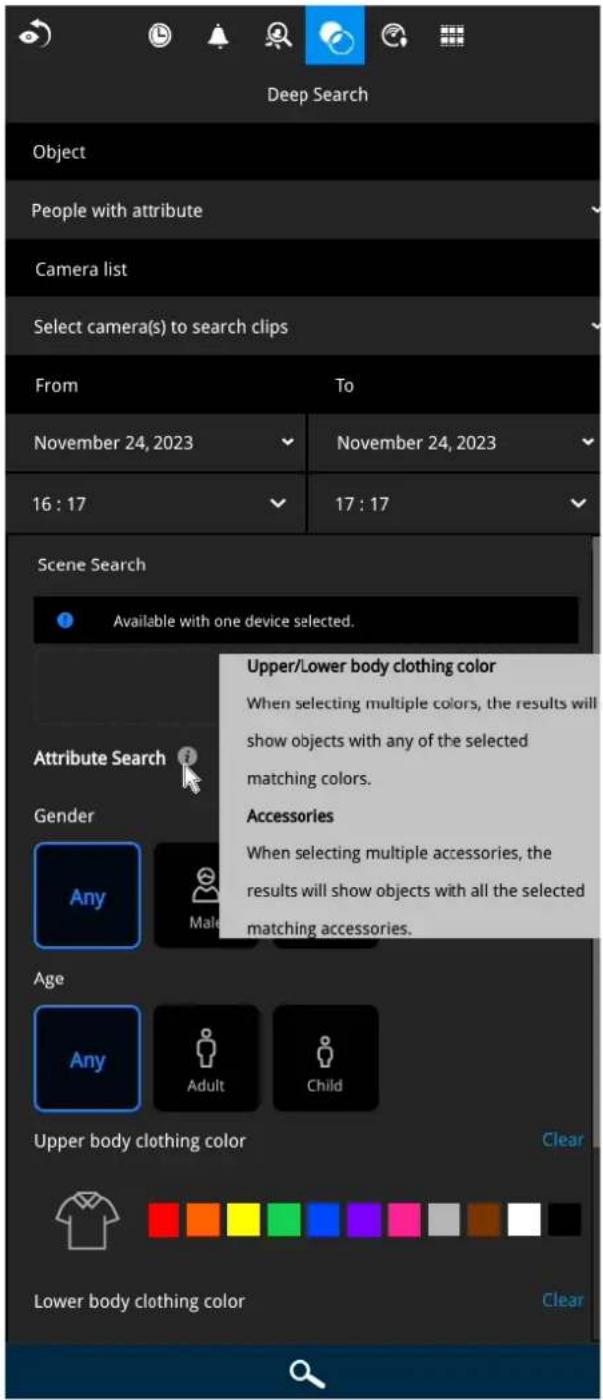
Select "People with attribute" or "Vehicle with attribute" if you want to find people or vehicles with specific appearances. Note that this search only applies to some premium camera models. Please visit VIVOTEK's website for details of the supported cameras.
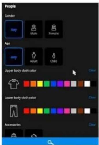
People with attribute
• People: Gender, Age, Clothing color
• Accessories: Backpack, Hat
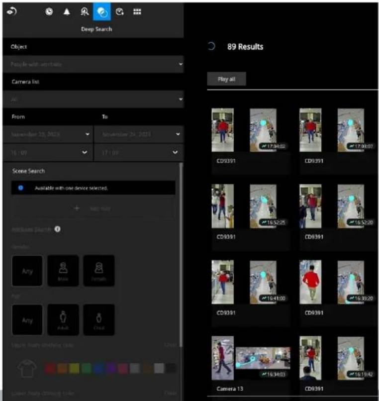
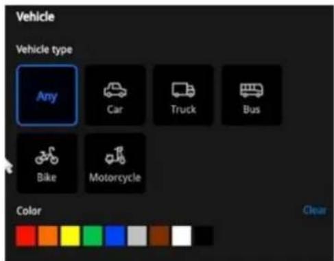
Vehicle with attribute
- Vehicle: Type, Color
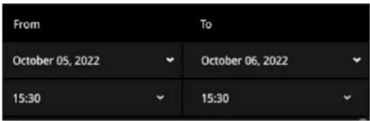
Choose a specific time span from the pull-down menu.
Select Attribute Search or Scene Search.
Attribute Search:
Find the people or vehicles with specific appearances from multiple cameras.
Scene Search:
Search for the object appearing or lingering in the virtual area or crossing a virtual tripwire.
Note that this search can only be applied to a single camera.
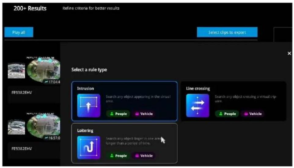
Users can click the button to select a search rule type:
- Intrusion: Draw a closed area in which you want to find related people or vehicles staying in this virtual area.
• Line crossing: Move the nodes to draw a tripwire to find related people or vehicles crossing this virtual wire. - Loitering: Draw a closed area in which you want to find related people or vehicles staying in this virtual area for more than a specified period.
Click Search to begin your search.
The number of results will be shown at the top of the results area.
If there are more than 200 search results, only the latest 200 results will be listed.
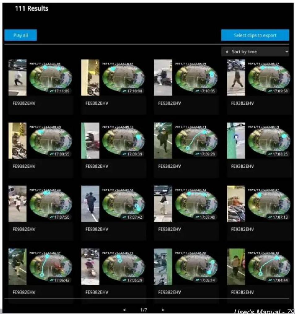
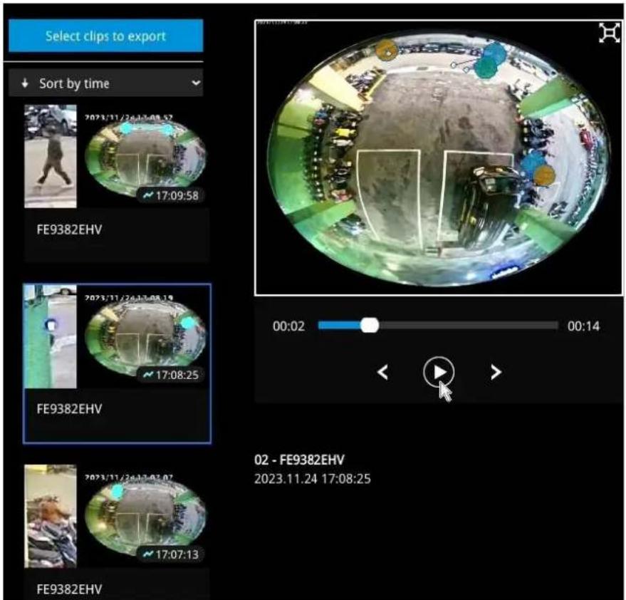
If there are search results after performing Deep Search, you can play each corresponding video thumbnail and take snapshots as needed.
IMPORTANT:
- Not all the cameras support finding all the object types. When users select one type of object, only the supported cameras will appear in the camera list. By default, all the cameras that support the object type will be selected. Users can click the device list and choose the cameras.
- When selecting multiple colors for clothing, the results will show objects with any of the selected matching colors.
- When searching for people with multiple accessories, the results will show objects with all the selected matching accessories.
- When searching for motorcycles or bikes, color attributes are not supported.
- Please visit the VIVOTEK'S website and check supported cameras for Deep Search. (https://www.vivotek.com/ai-driven/deep-search-system-requirement)
3-3-5. Smart VCA event search
This search panel enables the search for the detection results from Smart VCA analytics
functions. They include:
* Line crossing detection
* Intrusion detection
* Loitering detection
* Face detection
* Missing objection detection
* Unattended object detection
* Crowd detection
* Running detection
* Parking violation detection
* Smart tracking detection
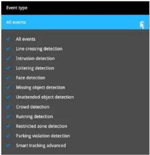
The event search takes effect when the related cameras are currently recording videos to the NVR.
The search function helps sorting through hours of videos, enabling you to quickly find a person or an event of your interest. This facilitates an effective search for a deployment across large surveillance areas. VCA events are recorded along with video recordings.
The NVR automatically detects cameras that come with the video analytics functionality. Note that the video analytics configuration should be separately configured on individual cameras; such as drawing the detection zone and detection line for Line-crossing detection.
You may also refer to the following documentation for more information about video analytics:
- Smart Motion Detection User Guide.
- Smart VCA User Guide.
- Smart 360 User Guide.
On the live view, you can also see the analytics rules and the bounding boxes indicating the detected objects while the analytics is taking place.
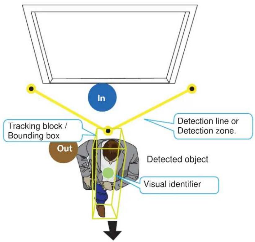
flowchart
graph TD
    A["In"] --> B["Tracking block / Bounding box"]
    A --> C["Out"]
    A --> D["Detection line or Detection zone."]
    A --> E["Detected object"]
    A --> F["Visual identifier"]
Below are the short introductions to these analytics functions:
Line Crossing Detection
The Line Crossing detection detects one or multiple people crossing a virtual tripwire. The traffic direction can be assigned on screen for people passing the line in one specific direction or in both directions.
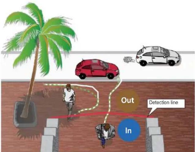
The applicable scenarios of this feature can be:
* Detects someone who enters a driveway, entrance, or exit through the virtual line.
* Detects and triggers an alarm in a predetermined direction.
* The detection line can be used as a fence boundary to know if someone has crossed the articulated line around a perimeter.
Intrusion Detection
VIVOTEK Intrusion Detection can be used to detect people entering or leaving a virtual area in the camera field of view.
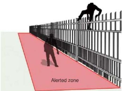
The applicable scenarios of this feature can be:
* Detects when a person enters a bank vault or school after office hours.
* Detects when a person leaves an emergency exit or fire escape, or any place that is normally forbidden from access.
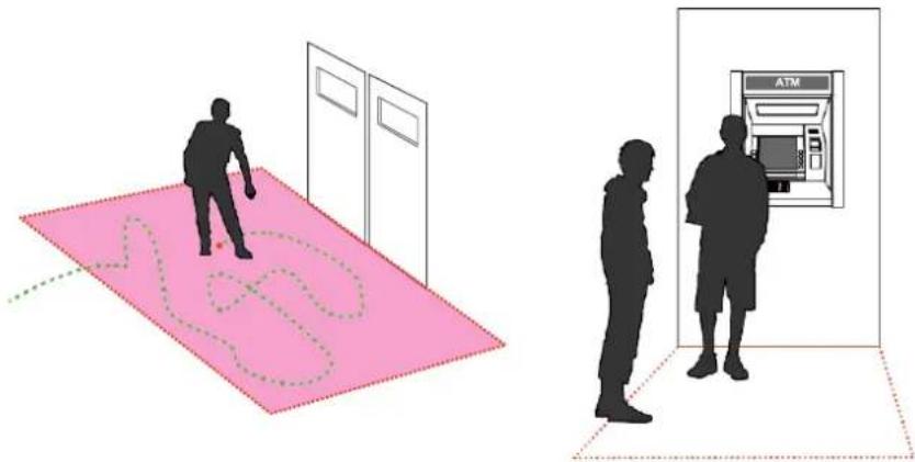
Loitering Detection
The Loitering detection can be used to detect a person of a group of people lingering in an area for longer than a preset time threshold.
natural_image
Illustration showing two silhouettes of people standing near a pink dotted map and an ATM machine (no text or symbols present)The applicable scenarios of this feature can be:
* Detects when a pserson is loitering at a walk-up of ATM lane.
* Detects when a person is loitering in a high-theft area of a store, or to prevent vandalism and break-ins.
* Detects when a person is loitering in an area that is normally not an access for visitors.
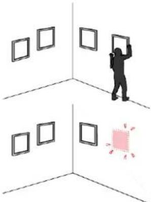
Missing Object Detection
The Missing Object detection can be used to detect the removal of a predefined asset from a surveillance scene.
natural_image
Illustration of a person standing in a corner with framed artworks, one holding a magnifying glass (no text or symbols)The applicable scenarios of this feature can be:
* In a campus setting, the Missing Object feature can be used to monitor high-risk areas for theft, such as the administrative offices, computer labs, or science laboratories.
* Detects when theft occurs in storage areas or warehouses. It is helpful when there are security personnel monitoring the scene, yet their attention went down through time.
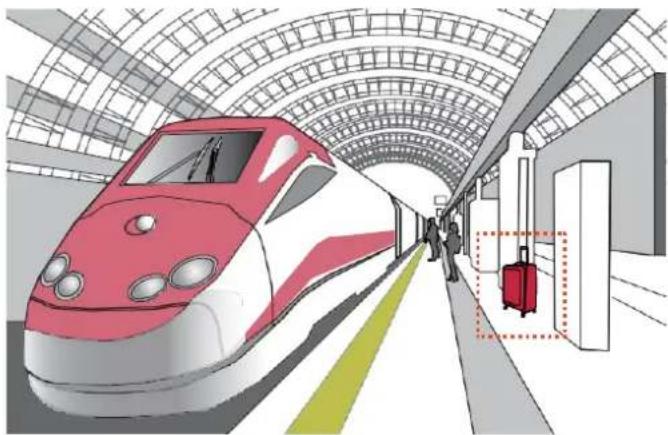
Unattended Object Detection
The Unattended Object detection can be used to detect objects intentionally or unintentionally left in scene.
natural_image
Illustration of a high-speed train at a station platform with passengers and luggage (no text or symbols)The applicable scenarios of this feature can be:
* Detects objects placed in front of an emergency exit.
* Detects objects left on subway tracks, platform, on a bridge, or in a bank lobby.
Face Detection
Face detection detects the presence of human faces in the field of view.
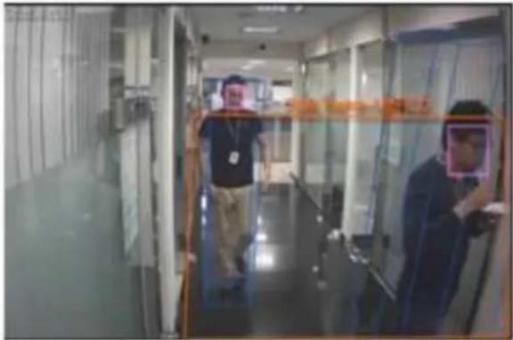
The applicable scenarios of this feature can be:
* By tagging the video frames which contain facial features, the administrator can later search for the video clips with presence of these faces in a more efficient manner. Instead of searching through hours of recordings, face detection can facilitate the process of forensic search in recorded videos. Objects irrelevant to facial features will be filtered out.
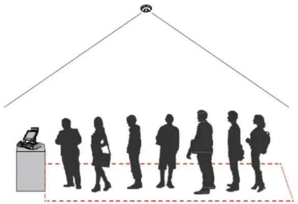
Crowd Detection
Crowd detection calculates the number of people in a specific area. When the number exceeds a preset number, an event is triggered.
natural_image
Silhouettes of people standing in a row under a roof structure, with a small device and a person at the base (no text or symbols)The applicable scenarios of this feature can be:
* Detects the congestion when the number of people in a region exceeds a preset number, e.g., 10 in a waiting line. For example, at an airport, when too many passengers are waiting in line, new checkpoints can be opened, and they can be directed to other checkpoints.
* To monitor a special area where at most one person is allowed inside. For example, one person is normally allowed in the area in front of an ATM machine or a strictly guarded entrance. Tailgating can occur if one uses his/her access card to open a gate while the other sneaks in following behind.
Running Detection
Running Detection can be used to detect people running from a crime scene or rioting occurs in a virtual area, such as gang fights. The algorithm can detect abnormal running behavior with a speed higher than the normal walking speed.
natural_image
Architectural line drawing of a building facade with window and doorways (no text or symbols)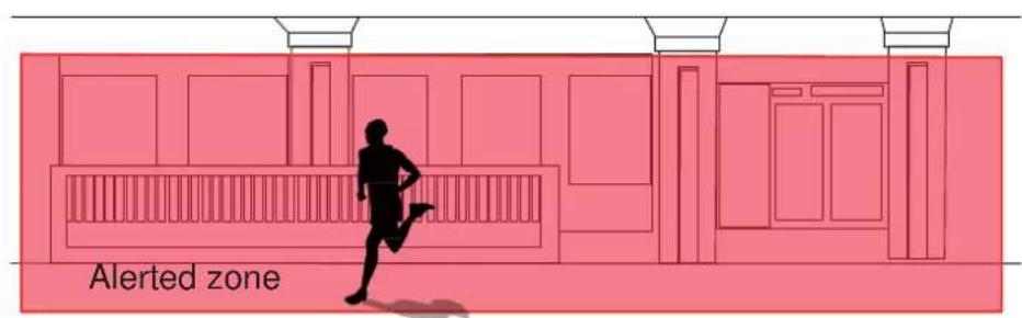
The applicable scenarios of this feature can be:
* Detects when a person is running from a crime scene.
* Detects unusual events when one or many people are running at abnormal speed such as on a plaza, shopping mall, etc., that is normally calm with casual activities.
Parking Violation
The Parking Violation detection helps when vehicles stay still for a period of time in an area. You can configure an area where parking can cause problems. You can configure an event notification when vehicles stay longer than a configurable period of time, e.g., 20 seconds.
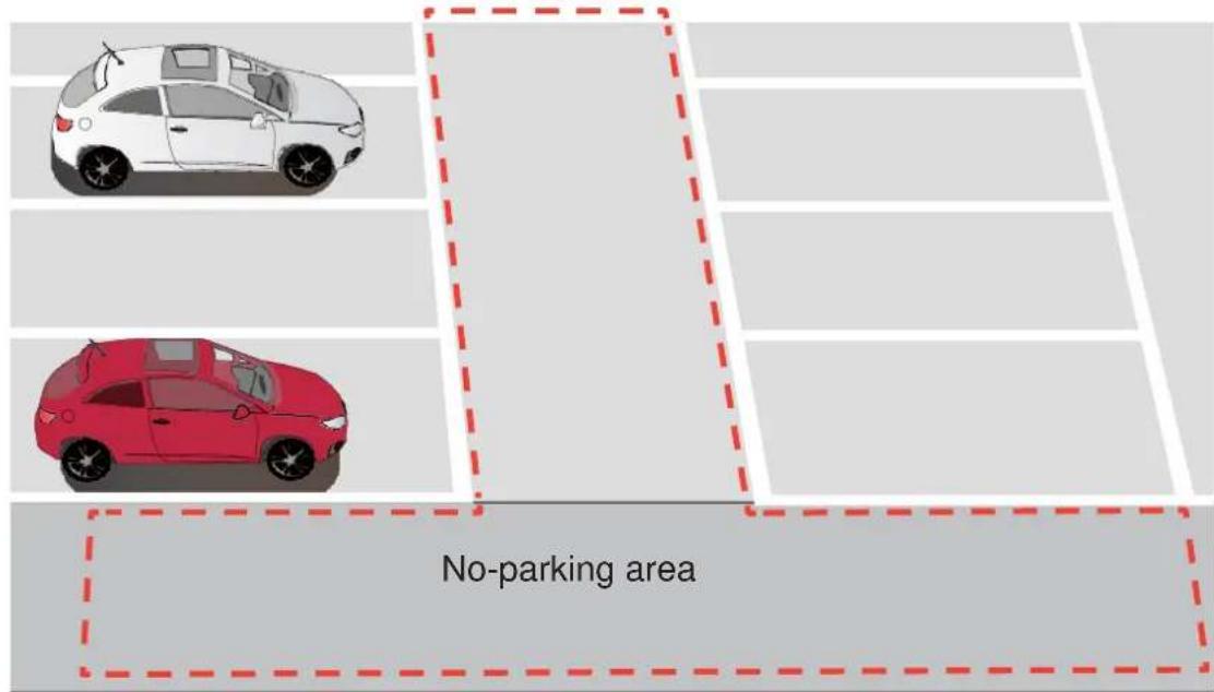
The applicable scenarios of this feature can be:
* Detects abnormal parking on the side of the road.
* To receive notifications when someone parks in front of an important access.
Restricted Zone
The Restricted Zone is a conditional detection where an intruder can be detected by entering a Restricted zone. The workers inside a facility will not trigger an alarm by entering a Defined zone first and then enter the Restricted zone.
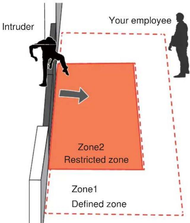
The applicable scenarios of this feature can be:
* Detects and triggers an alarm when a person or vehicle enters a restricted zone while someone passes through two zones will not trigger an alarm.
Smart Tracking
Below are some basic information for the Smart Tracking feature:
- The detection takes place at the pre-configured Preset positions. Tracking can only take place during a patrol dwell time.
- The PTZ camera then moves its lens to track the object found until the object moves away from the scene, or enters a shelter (e.g., getting into a car). The PTZ camera may lose the track when the field of view is blocked by a building. The camera then loses the track.
- The camera zooms in on the object when it is detected.
- A person cannot be detected when he is squatted, crawling, or riding on a scooter or bicycle since his body silhouette is merged or destroyed.
- Once the camera stops tracking an object, the FOV will return to the Home position.
- The maximum tracking range is 200 meters in radius.
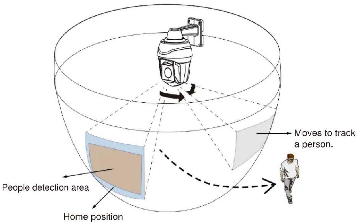
The Smart VCA search function can be accessed from the main portal using the Search button. When you are at the search panel, click on the Smart VCA search tab.
- Select the cameras that generate VCA events. Select at least one camera.
- Configure the time span within which the events occurred. Use the pull-down menu to change the From and To times.
- Select the Event types, namely, the pre-configured VCA analytics rules. Note that the event rules should have been properly configured on the individual cameras.
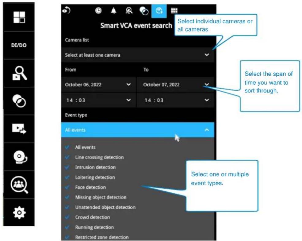
-
Click the Search button to begin the search. Depending on the scale of the search (how many cameras involved, and the span of recordings in search), the search should be completed in a few minutes.
-
The search results will display as thumbnail images. To view each short video clip, click on the thumbnail. The playback video window is located on the right. Click on the Expand/Shrink button watch the video in a full screen.
You can use the Esc button to leave the full screen. Click to select another thumbnail, or use the < or > buttons to view the previous or successive clips.
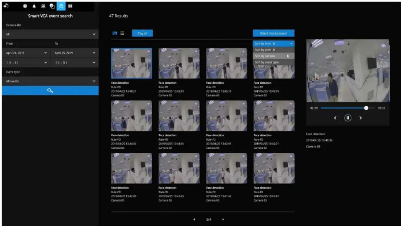
The default for the event recording setting is 5 seconds for pre-event, and 20 seconds for the post-event recording. You may change the parameters if the need should arise.
| Recording | 01 - Camera 01 | |||
| Media | 02 - | Event duration | ||
| Image | 03 - | Duration of camera events for next trigger: | 10 secs | |
| Motion d... | 04 - | Pre-event recording: | 5 secs | |
| PTZ settin... | Post-event recording: | 20 secs |
You may then select clips of your interest and click the "Select clips to export" button. The associated clips can be exported to a USB thumb drive.
You may use the sort menus on the upper right to sort your search results. If using the "Sort by event type" option, events of different types will be displayed in a successive order.
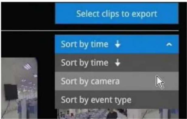
When exporting video clips, mouse over and select the small checkboxes on the thumbnails. Single-click to select video clips. When the selection is done, click the Export button to proceed.
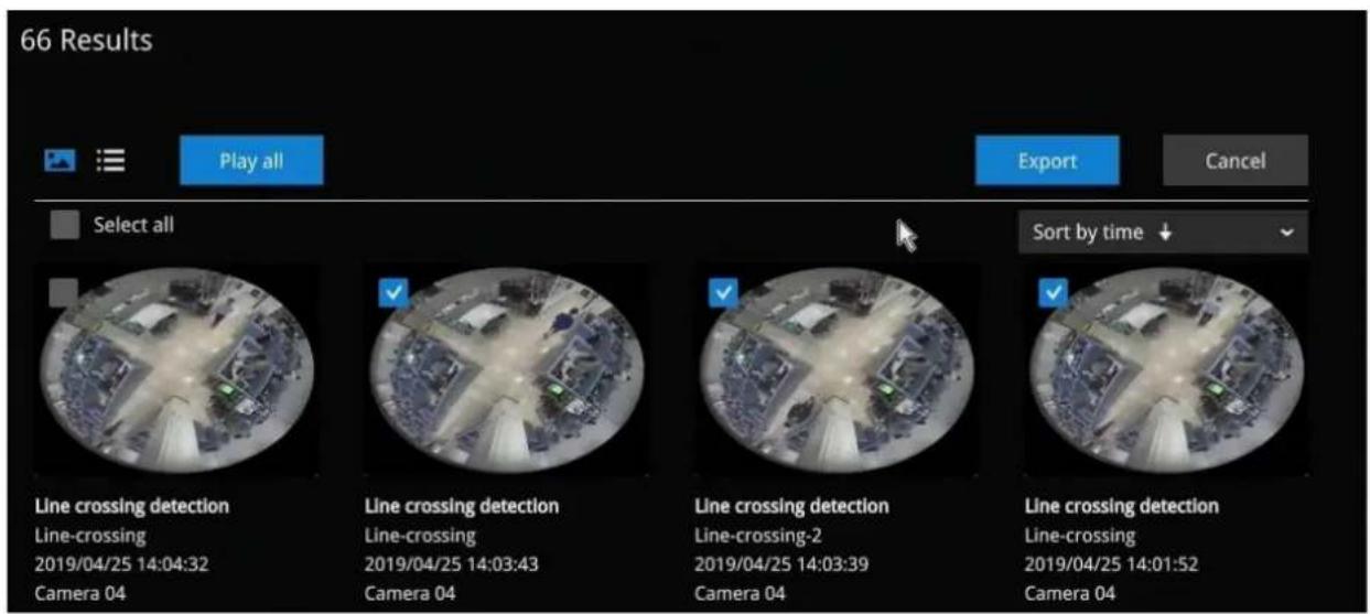
3-3-6. Storyboard
The Storyboard interface provides a glimpse of past recordings over a timeline. It looks and operates like doing the film editing after a film was shot.
To enter the Storyboard window, click on the Storyboard shortcut on the upper-left of screen.
Below are the screen elements of the Storyboard window:
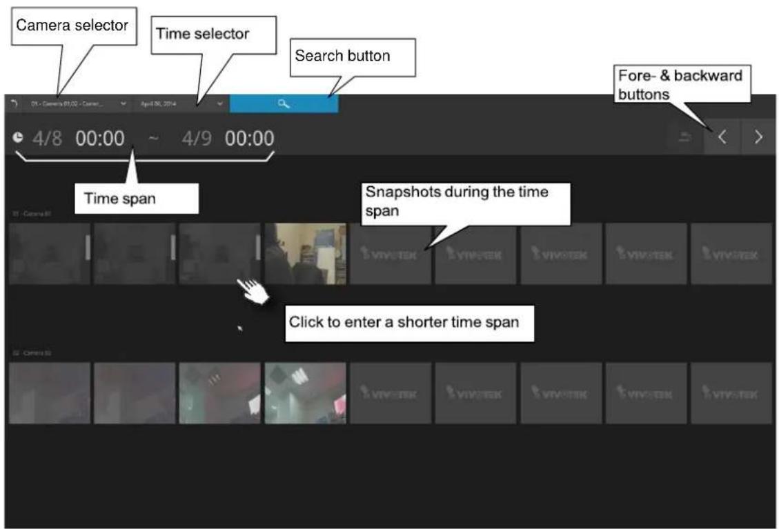
To search for a particular video footage, select the target cameras and the time of recording. On the Storyboard, the timelines of up to two cameras can be displayed.

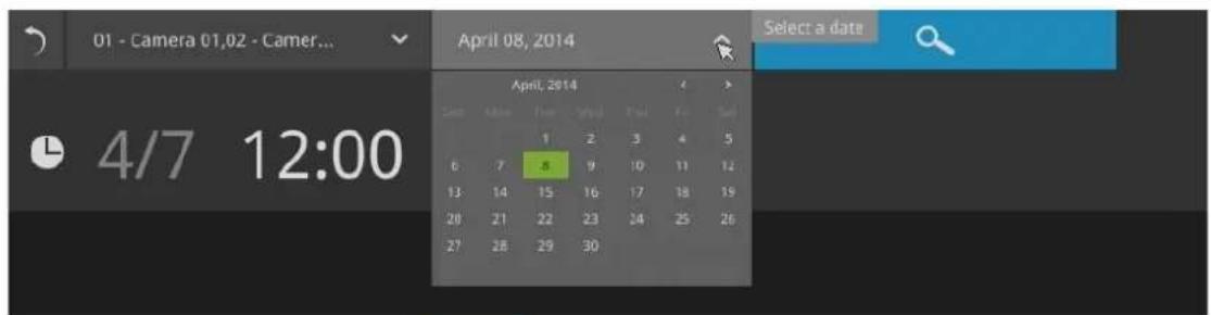
Click on the Search button
Mouse over the line of snapshots to display its time of recording. Click on a snapshot of your interest. The time of recording is immediately displayed on top of it.
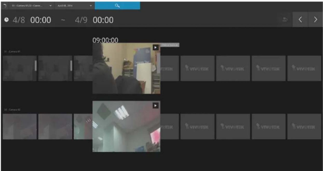
The detailed search is based on a narrow-down criteria. The search begins from a 24-hour time span, and then moving in to a 4-hour, 1-hour, 10-minutes, and 2-minutes span. When the screen displays a 24-hour span, each snapshot represents a 3-hour time span.
Each click on a snapshot brings you deeper into the timeline.
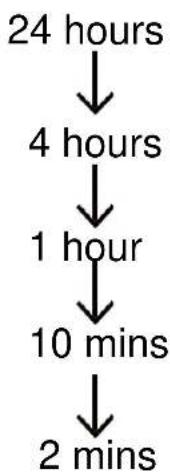
flowchart
graph TD
    A["24 hours"] --> B["4 hours"]
    B --> C["1 hour"]
    C --> D["10 mins"]
    D --> E["2 mins"]
Below is a sample screen showing the screen of a one-hour time span. Each snapshot represents a point in time 7.5 minutes apart. Click on a snapshot of your interest to get deeper into the timeline.
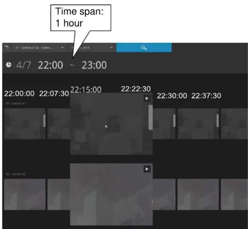
If you find yourself in the wrong segment on the timeline, use the buttons on the upper-right of the screen to travel.
The definitions of these buttons depend on the time span of your current position. For example, if you are in a 4-hour time span, the "Back to previous state button" will bring you back to the 24-hour time span.
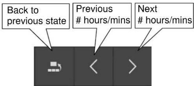
The smallest time span is 2 minutes. And on the screen of 2-mins span, each snapshot represents a 15 seconds video footage.
You can then click on the Play button ▶ to playback the recorded footage.
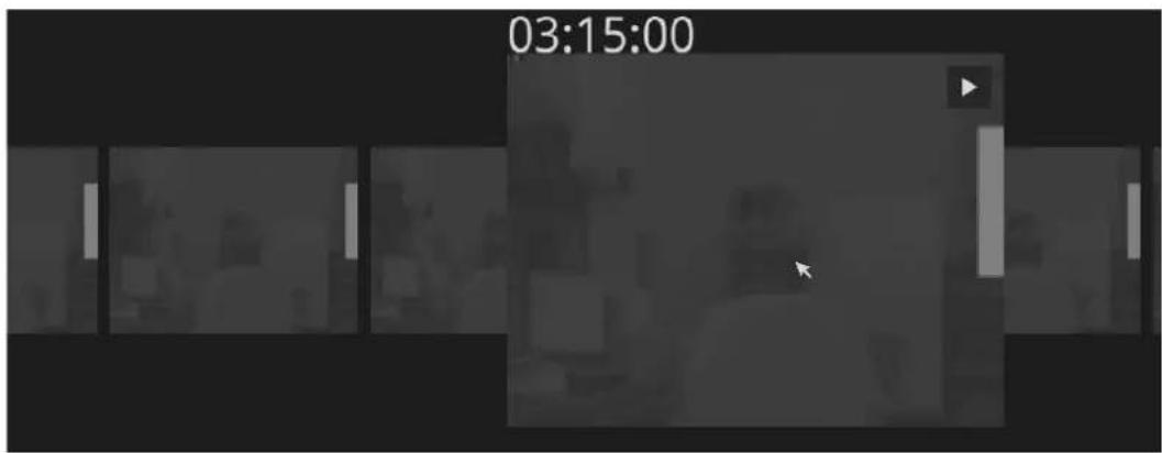
The playback window will appear. Please refer to page 67 for the operation details.
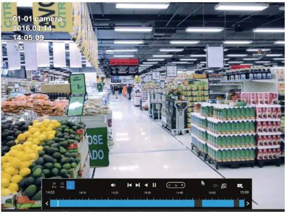
To return to the Live View window, click on the Back to Search recording clips button and the Back to Live view button on the upper-left of the screen.
3-4. Export recordings

The Export recordings button allows users to directly select a piece of recordings by a specific camera, and export that to a USB thumb drive. Users can select one or multiple cameras, select a period of time in which the recording took place, and then click export.
The max. length of recording export is 24 hours.
To export recordings:
- Attach a USB thumb drive formatted in FAT format to the NVR's USB port.
- Select one or multiple cameras from the list.
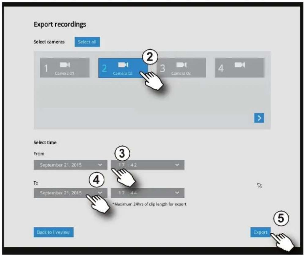
- Select the start time of the period of recording time.
- Select the end time of the period of recoding time.
- Click the Export button.
A tar file containing a log file will also be created, including the information for export time, user, camera name, recording time span, etc.
- The Export progress will be shown.
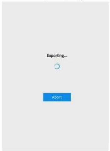
- When the Export process is done, select to resume another export or go back to the live view.
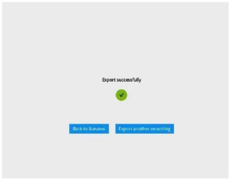
Note that the Export process can take a long time if the time span of the selected video is very long.
3-5. Settings
3-5-1. Settings - Overview

Click the Settings button to start the camera and system settings window. A confirm box will prompt. Enter Username and Password to proceed.
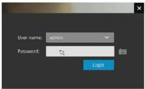
The system will default to the overview page displaying the camera connection and storage statuses. An empty position will be left in blank, and a disconnected camera will be indicated as 📄. The storage volume usage is displayed as the used and unused spaces.
On a web console, the Stop Buzzer, Reboot, and Power-down buttons are available on the overview. There are critical conditions that can sound the system buzzer, such as a disk failure.
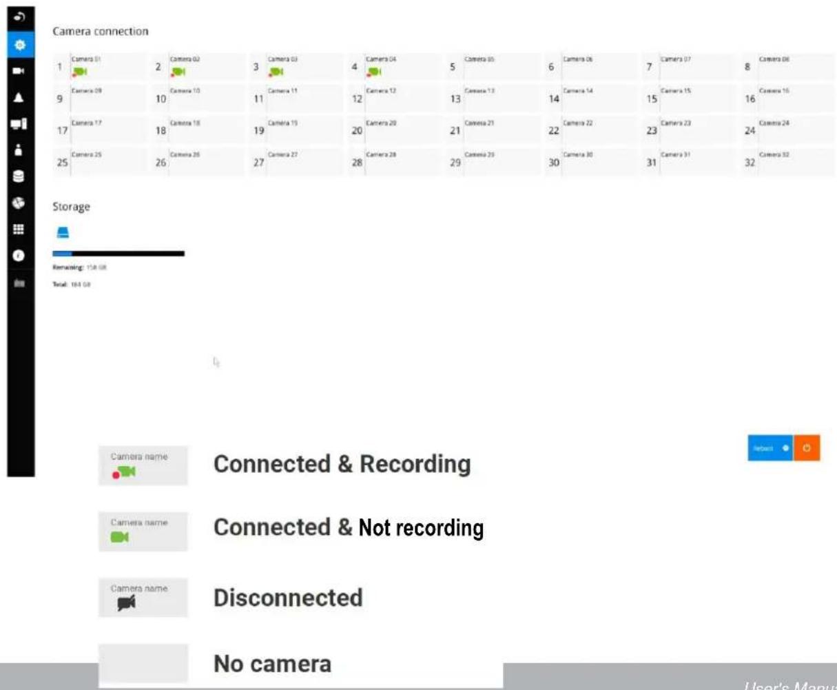
The Camera menu provides access to Management, Recording, Media, Image, Motion detection, and PTZ settings pages.
3-5-2. Settings-Camera-Management
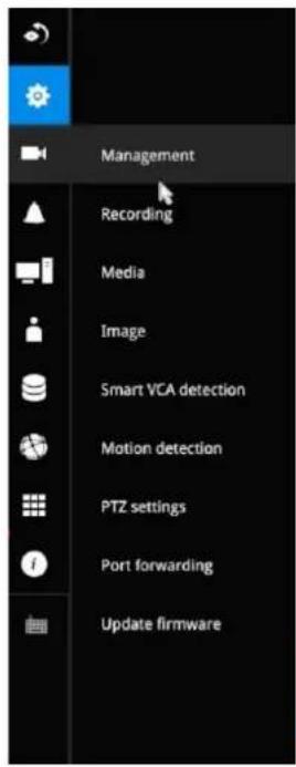
On the camera Management page, you can configure the following:
- Recruit or disband cameras.
- Create a camera name.
- Binding: Designate how a camera is recognized. The default is MAC binding. The NVR recognizes a camera by its MAC address regardless of IP changes. If set to IP binding, static IP setting is preferred. If IP changes occur, the NVR may not be able to access the cameras.
- Protocol: You can select ONVIF to recruit cameras made by other manufacturers.
- Assign Username and Password, or apply the credentials to all cameras in your configuration.
- Change the Network settings.
- Change the cameras' positions on the layout screen.
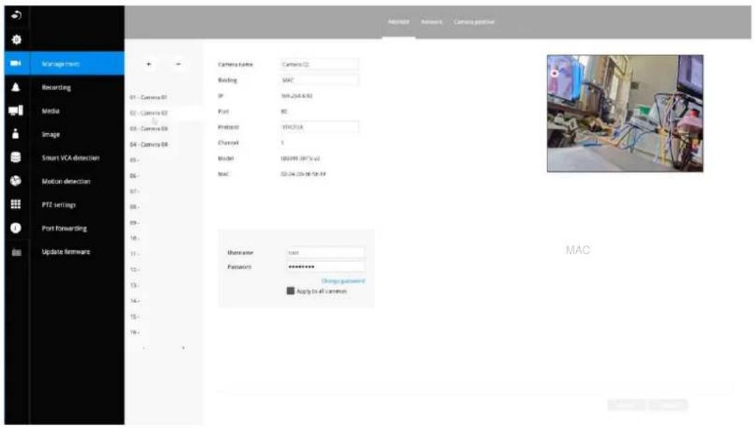
For camera name, you can enter up to 64 alphabetic and numeric characters including [0-9][a-z][A-Z][_][-]\. For user name and password, you can enter up to 64 alphabetic and numeric characters including [0-9][a-z][A-Z][!][\][%][-].[@]['\~].
For legacy cameras, the NVR supports RTSP connections since firmware release revision 2.6.x.
To manually add a legacy camera,
- Select an empty camera entry,
- Click the Add button,
-
Select RTSP as the protocol.
-
The original rtsp address is: rtsp://
: / . For example, when the access name for stream 1 is set to live.sdp: rtsp://192.168.5.151:554/live.sdp.
However, you only need to enter IP address and "live.sdp" in the URL field. The system automatically fills in the other parameters.
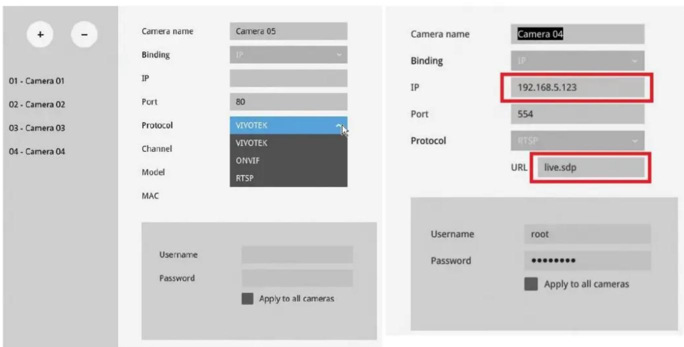
Note the following when using RTSP connections:
- RTSP cameras do not support event recording in the Schedule settings.
- RTSP cameras do not support FTP, Camera DO, and PTZ as the Alarm action.
- RTSP cameras do not support camera's related settings such as Network, Video, Audio, and Display configurations.
- RTSP cameras will be indicated by an RTSP tag in the device list.
- RTSP cameras do not support Motion detection configuration.
- RTSP cameras can not be selected as an alarm trigger.
In Media > Stream management page, the related Video, Audio, and stream configuration for RTSP cameras cannot be edited. The RSTP cameras will be tagged.
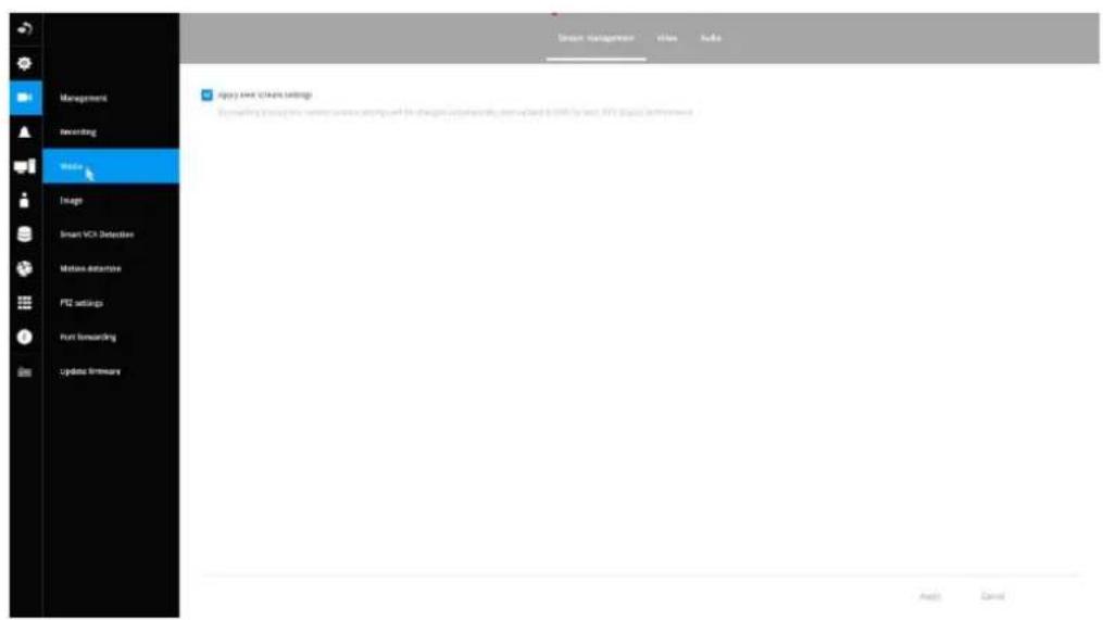
To recruit cameras:
- Click on the Add + button. A list of cameras in the same subnet will appear.
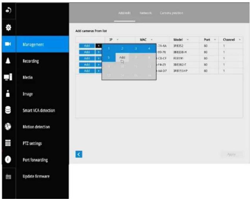
- Click the Add button, the camera will be placed at an unoccupied position. You may also expand the menu on the side of the Add button to select a position number.
- When a camera is added, it should appear on the graphical placement below.
- Click the Apply button after you added cameras.
- You may click the page back button < to return to the previous window.
To disband cameras:
- Click on the Remove

button. A list of cameras will appear.
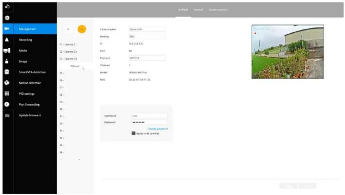
- The Remove button will turn yellow 🔍. Mouse over to the camera you want to remove, and its entry will display the Remove message.
- Click on the Remove message. The camera should then disappear from the camera list. The recording from that camera will also be discontinued.
Network
On the Network tabbed window, you can configure the network type, IP address, and the connection ports for video streaming. The cameras connected to the NVR PoE ports are placed behind a default gateway 10.1.1.1 or 192.168.2.1.
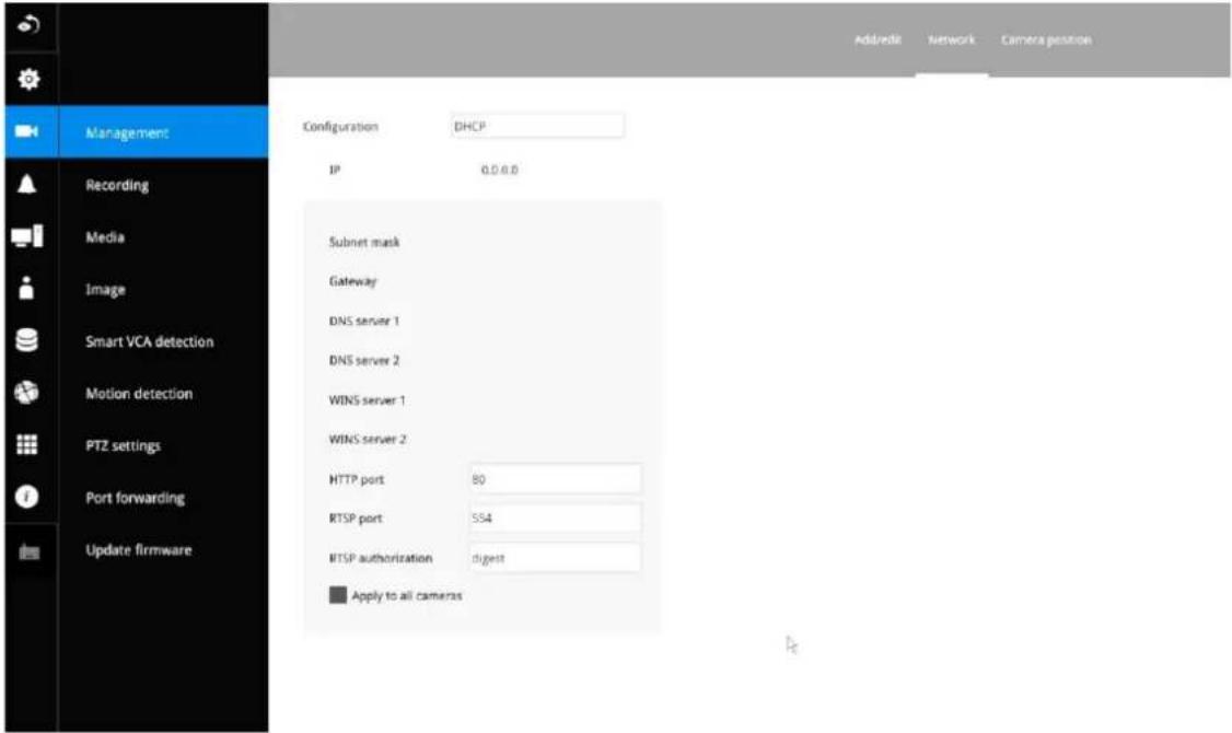
You can select DHCP as the method for cameras to acquire IP addresses, or you can manually configure static IPs for a single or all cameras. Although the NVR can remember the MAC addresses of cameras, if IPs are changed under the DHCP configuration, your NVR may still fail to connect the cameras. Please consult your network administrator for details about network settings.
It is usually not necessary to change port numbers for the HTTP and RTSP ports unless there is a conflict in your network environment.
Camera position
To change a camera's position on the Live view layout, click and drag a camera to an unpopulated position. Note that you cannot swap the positions of two cameras by dragging a camera onto a position already populated by the other. Also, the camera index number on the management list is not affected by the change of positions.
Click the Apply button for the configuration change to take effect. The position screen displays the current layout on the Live view screen.
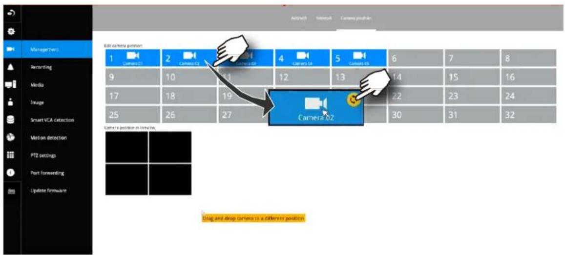
3-5-3. Settings-Camera-Recording
Recording options
On the camera Recording page, you can configure the following:
- Configure the duration of camera events, for the concern that camera can be too frequently triggered.
- Enter the Pre- and Post-event recording time. The triggering events can be DI, DO, Motion detection, PIR, or Tampering detection. A recording length of 10 seconds of pre-event and up to 300 seconds of post-event can be configured.
- The default recording stream is Main Stream. You can still change the streaming characteristics. Note that you cannot assign the recording task to other video stream.
- Enable or disable audio recording. Note that audio transmission through HDMI
- cable is currently not available.
- Change the life expectancy of the recording data.
- You can apply a typical configuration to all cameras using the Apply to all cameras checkbox.
Dual stream recording is also supported if the need should arise.
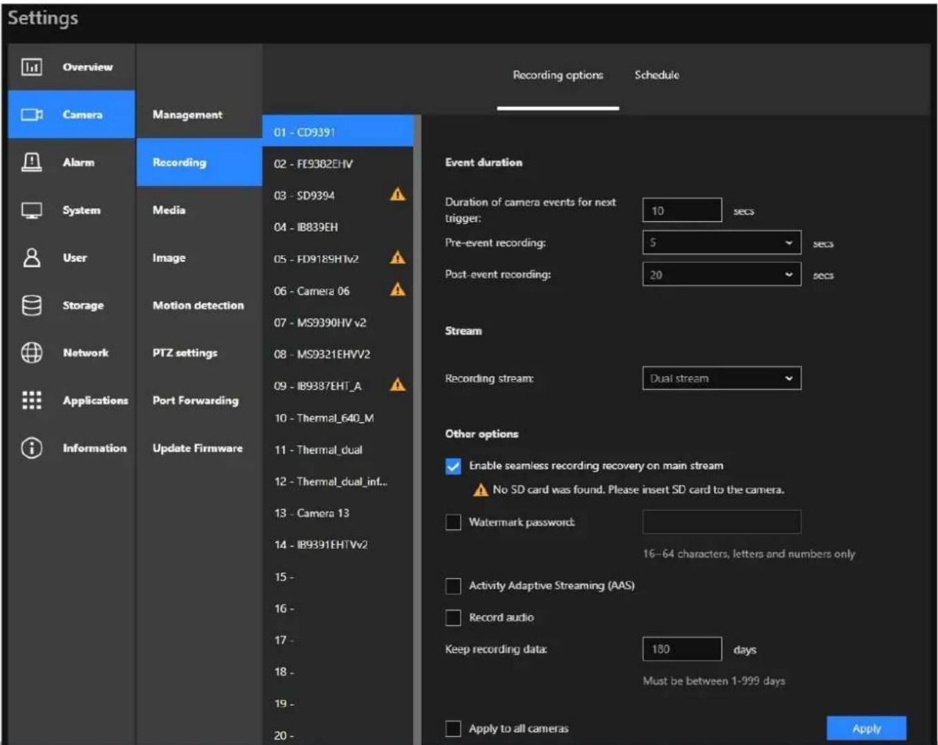
Also, if you enable seamless recording recovery on mainstream (while an SD card is installed in the corresponding camera), you can ensure the video recording will continue if the network connection or electric power is interrupted. That is, after the network connection or electric power restores, the NVR will recover the videos recorded on the SD card and ensure the video recording is not interrupted. In other words, in the event of network connection loss or power interruption, Seamless Recording activates to safeguard video recordings. By seamlessly backing up recording data to the SD card installed in the corresponding camera, users can ensure the preservation of critical footage under various circumstances.
NOTES:
- Recording data will not be backed up if the camera is connected to the NVR's PoE port in the event of a power interruption on the NVR.
- Please ensure that each specific camera is equipped with a compatible SD card for seamless recording functionality. RTSP & ONVIF cameras do not support seamless recording recovery.
- Do not update the clock on the camera if seamless recording recovery is in progress. This is to avoid possible repeated playback or broken video files.
- If a video file is being recorded while the network connection or electric power is interrupted, this video file is corrupted. So, seamless recording recovery does not apply.
-
You can refer to the User Manuals that come with your network cameras for more discussions of these configurable options.
-
Watermark password: Configure a password in a length of 16 to 64 characters. You can use it to verify the authenticity of exported videos using the included video player.
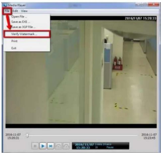
Select File > Verify Watermark.
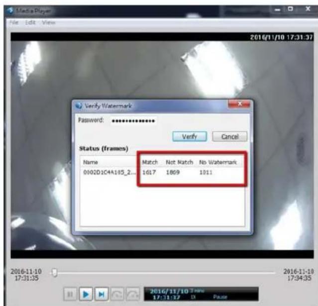
Enter the password to verify. If the Not match value is 0, the video is the original and has not been tampered with.
Recording Schedule
By default, all video feeds from cameras are recorded at all time. You can modify the recording task using the schedule tool:
- Click to select a recording condition's checkbox-1. Continuous recording 🔒, Event recording

and 3. Clear (no recording).
- Click and drag on the cells on the timetable. For example, to stop the recording during a period of time, select the Clear checkbox and move the cursor across the timetable minimum unit on the table is half an hour.
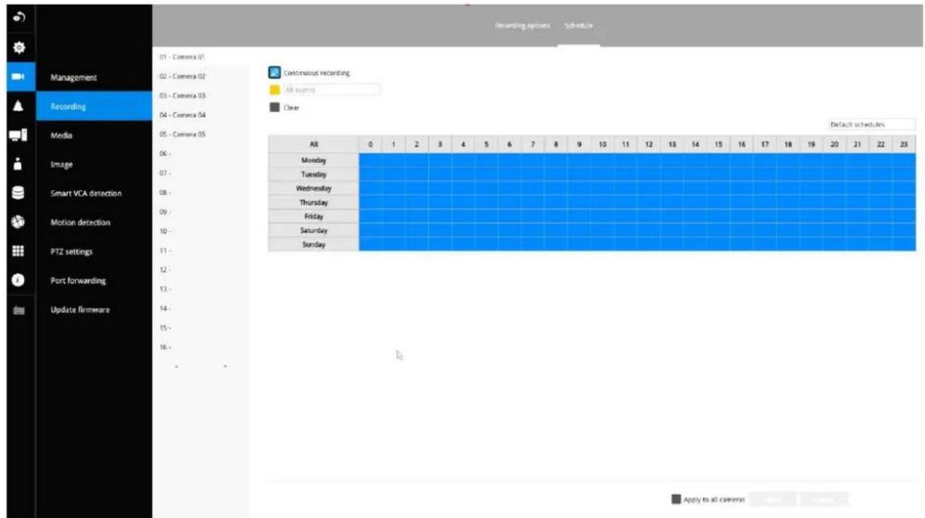
- You may also use the scheduler tool on the right to facilitate the process. You can select a condition checkbox, and then select the All day, Work hour, Off duty, Working day, Weekend options to apply a time selection.
- Repeat the process on individual cameras or select the Apply to all checkbox if the schedule can apply to all cameras.
- When done with the configuration, click on the Apply button.
Note that Event-triggered recording and continuous recording cannot be taking place at the same time.
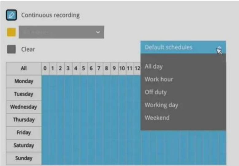
3-5-4. Settings—Camera—Media
The NVR automatically changes camera stream settings when cameras are added.
If users want to manually configure camera stream setting, they can disable this function. The default for the automatic configuration is,
- Main stream: H.265 5M
- Sub stream: H.264 360p
The Main stream is set for higher video resolution & Network bandwidth use. The Sub stream requires lower video resolution & Network bandwidth. Users can not associate individual camera stream with either the Main or Sub stream.
- Main stream: the 1st stream of camera with H.265/5Mbps/max frame rate.
- Sub stream: the 2nd stream of camera with H.264/360P/1Mbps/max frame rate
- If the connected camera does not support the values described above, the NVR will take the value close to the specifications (resolution/ bitrate)
- The Main stream is applied with 2x2 or other layout of a larger view cell.
- The Sub stream is applied with 3x3 or other layouts of a smaller view cell.
On a local console, the P (Panoramic or M (Middle) view cell will display the Main stream.
On a web console, the Main stream is displayed on a 1x1 layout. The Sub stream is displayed on other layouts.
For Playback:
Only the Main stream is selected for Playback display. The exported clip file should be the same as selected as the stream type. The Main stream will be the default.
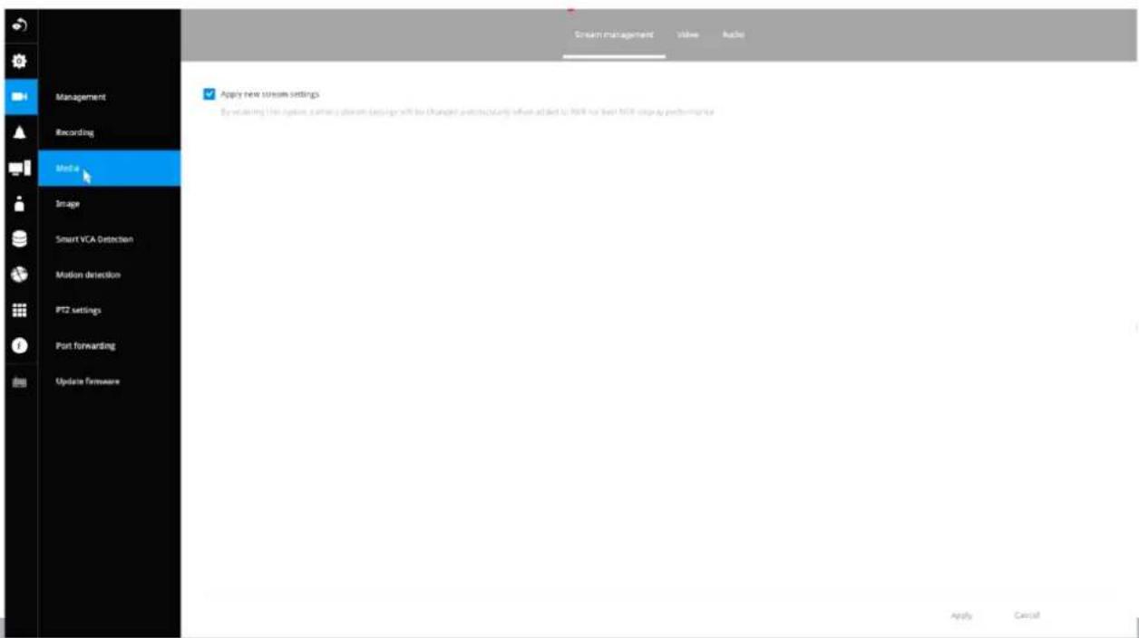
The NVR adaptively selects to display a video stream of a different resolution when it is displaying on a smaller view cell or a full screen.
By default, the Recording stream is Main Stream, which is recorded to the H.D.D.
Video
The Video window allows you to configure all video streams (the no. of stream available can be different for different models). You can configure the following:
- Main stream/ Sub stream: Select to configure two basic categorized streams.
- Codec: video compression codec in H.264, MPEG-4, or MJPEG. Note that MPEG-4 is not supported for Live view.
-
Frame size: video resolution. Note that due to the limited CPU resources, you may not be able to change the resolution to a very high value, e.g., 5MP in the 1920x1920 resolution.
-
Maximum frame rate: the highest frame rate.
-
Intra frame period: How often an I-frame will be inserted into the video stream.
-
Smart Stream II: Some newer camera models come with Smart Stream features. Please refer to the next page for detailed information.
-
Video quality: You may either select Constant bit rate or Fixed Quality as the defining rules for video transmission:
| Constant bit rate | Places a packet size threshold on video frames; This guarantees the frame rate per second performance, yet image quality can be compromised if bandwidth is not sufficient in your network environment. |
| Fixed Quality | Guaranteed video quality, and to ensure image quality, some frames may be dropped when bandwidth is not sufficient. |
When done with the configuration, click the Apply button.
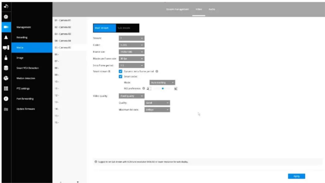
■ Dynamic Intra frame period
High quality motion codecs, such as H.265, utilize the redundancies between video frames to deliver video streams at a balance of quality and bit rate.
The encoding parameters are summarized and illustrated below. The I-frames are completely self-referential and they are largest in size. The P-frames are predicted frames. The encoder refers to the previous I- or P-frames for redundant image information.

H.264/265 Frame Types
By dynamically prolonging the intervals for I-frames insertion to up to 10 seconds, the bit rates required for streaming a video can be tremendously reduced. When streaming a video of a static scene, the Dynamic Intra frame feature can save up to 53% of bandwidth. The amount of bandwidth thus saved is also determined by the activities in the field of view. If activities occur in the scene, firmware automatically shortens the I-frame insertion intervals in order to maintain image quality. In the low light or night conditions, the sizes of P-frames tend to be enlarged due to the noises, and hence the bandwidth saving effect is also reduced.
Streaming a typical 2MP scene normally requires 3\~4Mb/s of bandwidth. With the Dynamic Intra frame function, the bandwidth for streaming a medium-traffic scene can be reduced to 2\~3Mb/s, and during the no-traffic period of time, down to 500kb/s.
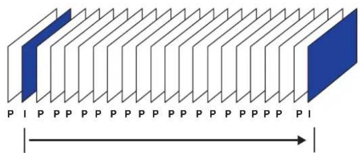
natural_image
Simple line drawing of a house and two trees on a line, labeled 'Static scene' below (no text or symbols on the diagram itself)Dynamic Intra Frame w/ static scenes
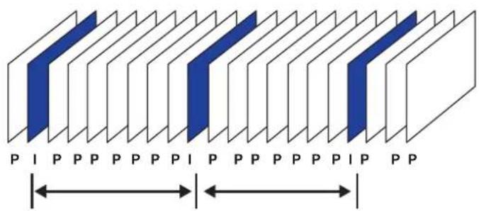
Dynamic Intra Frame w/ activities in scenes
■ Smart codec effectively reduces the quality of the whole or the non-interested areas on a screen and therefore reduces the bandwidth consumed.
You can manually specify the video quality for the foreground and the background areas.
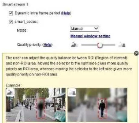
Slide bar to the right - higher quality in the ROI areas
Slide bar to the left - higher quality in the non-ROI areas.
Select an operation mode if Smart codec is preferred.
- Auto tracking: The Auto mode configures the whole screen into the non-interested area. The video quality of part of the screen returns to normal when one or more objects move in that area. The remainder of the screen where there are no moving objects (no pixel changes) will still be transmitted in low-quality format.
- Manual: The Manual mode allows you to configure 3 ROI windows (Region of Interest, with Foreground quality) on the screen. Areas not included in any ROI windows will be considered as the non-interested areas. The details in the ROI areas will be transmitted in a higher-quality video format.
As illustrated below, the upper screen may contain little details of your interest, while the sidewalk on the lower screen is included in an ROI window.
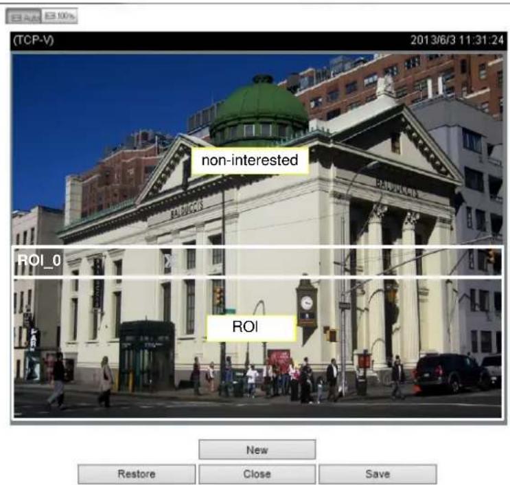
As the result, the lower screen is constantly displayed in high details, while the upper half is transmitted using a lower-quality format. Although the upper half is transmitted using a lower quality format, you still have an awareness of what is happening on the whole screen.
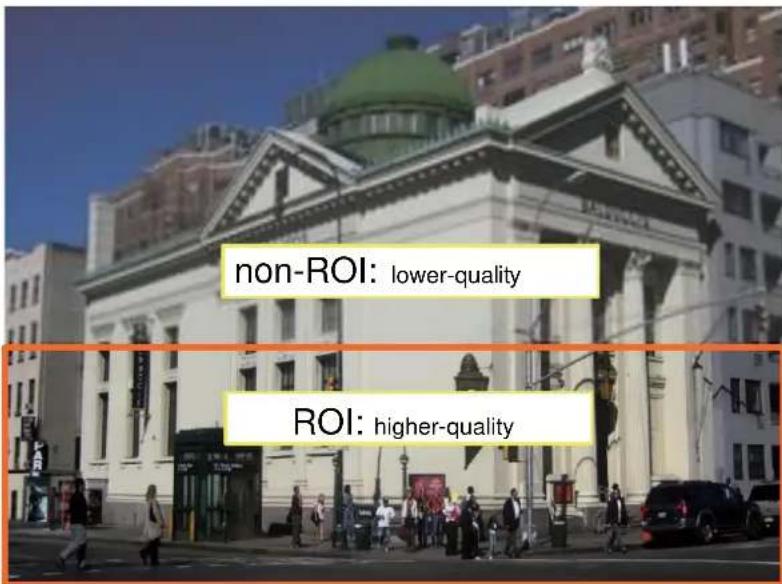
- Hybrid: The major difference between the "Manual" mode and the "Hybrid" mode is that:
In the "Hybrid" mode, any objects entering the non-interested area will restore the video quality of the moving objects and the area around them. The video quality of the associated non-interested area is immediately restored to normal to cover the moving objects.
In the “Manual” mode, the non-interested area is always transmitted using a low-quality format regardless of the activities inside.
Quality priority: (Help)

- Quality priority: Use the slide bar to tune the quality contrast between the ROI and non-interested areas.
The farther the slide bar button is to the right, the higher the image quality of the ROI areas. On the contrary, the farther the slide bar button to the left, the higher the image quality of the non-interested area.
In this way, you may set up an ROI window as a privacy mask by covering a protected area using an ROI window, while the remaining screen becomes the non-interested area. You may then configure the non-interested area to have a high image quality, or vice versa.
You should also select the Maximum bit rate from the pull-down menu as the threshold to contain the bandwidth consumption for both the high- and low-quality video sections in a smart stream.
Audio
The Audio window allows you to configure all audio codec, sampling rate, and Microphone input gains. Depending on design of the camera models, some codecs may not be available. Also, there are cameras that come without embedded microphones.
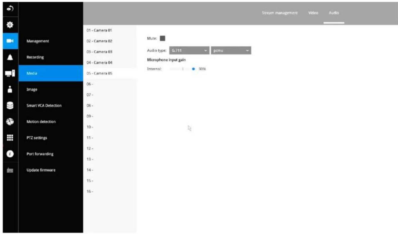
3-5-5. Settings - Camera - Image
Display
The Display window allows users to tune the image display options:
- Video name: the video name is displayed on the title bar that is displayed on each view cell. The screen shot below shows a name as "Speed dome."

- Video name and timestamp: Default is enabled. If enabled, the video name and time is displayed on the view cell.
- Color: Select color or black and white display.
- Power line frequency: Depending on power line frequency of your country, select a matching option, NTSC 60Hz or PAL 50Hz, to avoid image flickering due to unmatched electricity.
- Video orientation: select these options if the image from camera needs to be vertically or horizontally flipped.
- Click Restore to poll for the original settings or click the Apply button to finish the process.
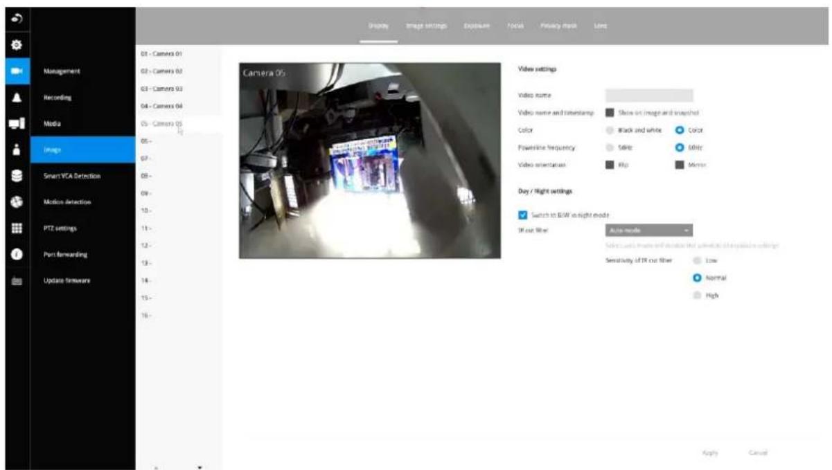
Day/Night settings
Switch to B/W in night mode
Select this checkbox to enable the Network Camera to automatically switch to Black & White display during the night mode.
IR cut filter
With a removable IR-cut filter, this Network Camera can automatically remove the filter to let Infrared light pass into the sensor during low light conditions.
■ Auto mode (The Day/Night Exposure Profile will not be available if Auto mode is selected) The Network Camera automatically removes the filter by judging the level of ambient light.
■ Day mode
In day mode, the Network Camera switches on the IR cut filter at all times to block infrared light from reaching the sensor so that the colors will not be distorted.
■ Night mode
In night mode, the Network Camera switches off the IR cut filter at all times for the sensor to accept infrared light, thus helping to improve low light sensitivity.
Image settings
The Image adjustment window allows users to tune the basics about image display options:
- Color: Select to display image as color or black and white.
- Brightness.
- Saturation.
- Contrast.
- Sharpness.
- High TV line, Gamma curve, low light compensation, etc. The rest of the options depend on the lens and image sensor type of each individual camera. Therefore, the options here can vary. For unique options coming with each individual camera, please refer to their User Manuals for more information.
Click Restore to poll for the original settings or click the Apply button to finish the process. For features common among cameras, you may select the Apply to all cameras checkbox.
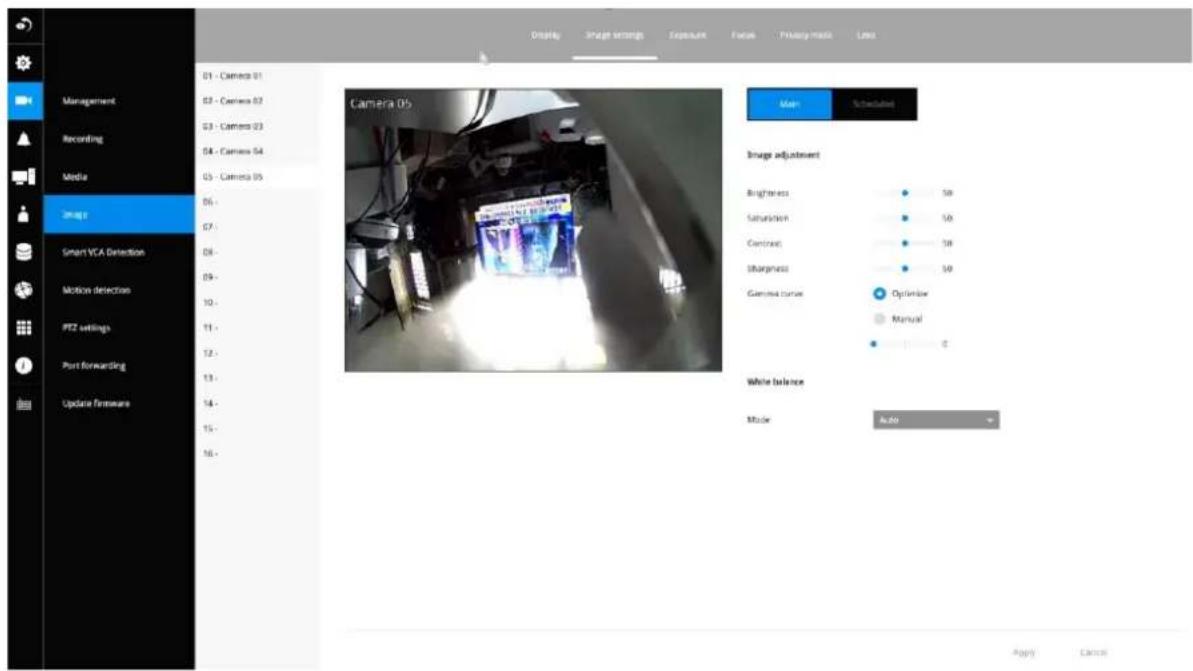
Scheduled:
Configure a different image settings for a different span in time, such as the night mode, with a different lighting condition.
Exposure:
Enable WDR Pro: This refers to the Wide Dynamic Range function that enables the camera to capture details in a high contrast environment. Use the checkbox to enable the function, and use the slide bar to select the strength of the WDR Pro functionality, depending on the lighting condition at the installation site. You can select a higher effect when the contrast is high (between the shaded area and the strong light behind the objects).
Enable WDR enhanced: This function allows users to identify more image details with an extreme contrast from an object of interest with one shadowed side against a bright background, e.g., an entrance. You may select the Enable WDR enhanced checkbox, and then adjust the strength (low, medium, high) to reach the best image quality.
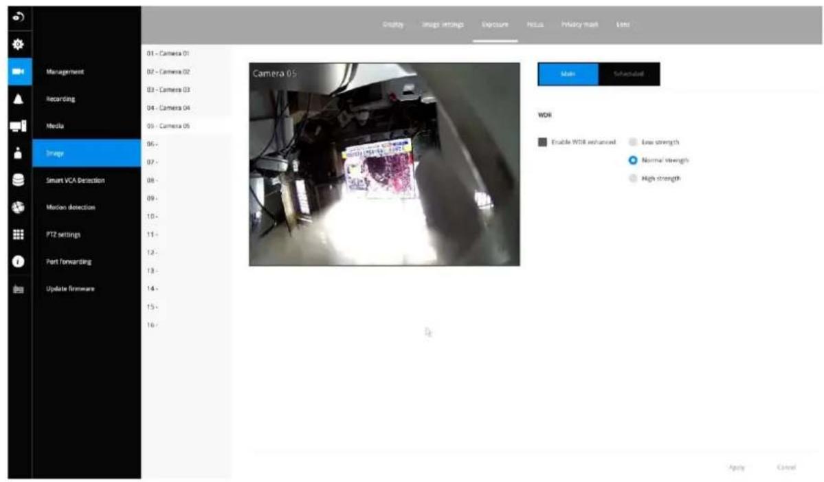
Focus:
Enable WDR Pro: This refers to the Wide Dynamic Range function that enables the camera to capture details in a high contrast environment. Use the checkbox to enable the function and use the slide bar to select the strength of the WDR Pro functionality, depending on the lighting condition at the installation site. You can select a higher effect when the contrast is high (between the shaded area and the strong light behind the objects).
Enable WDR enhanced: This function allows users to identify more image details with an extreme contrast from an object of interest with one shadowed side against a bright background, e.g., an entrance. You may select the Enable WDR enhanced checkbox, and then adjust the strength (low, medium, high) to reach the best image quality.
- Wait for the scan to complete. After a short while, the clearest image obtained should be displayed and the optimal focus range achieved. Use the arrow marks on the sides to fine-tune the focus if you are not satisfied with the results. You may still need to use the arrow marks to fine-tune the focus depending on the live image on your screen. “>” means moving from wide to tele end; and “<” tele to wide.
The methodology of using the Resize Buttons at the upper left corner of the streaming window is the same as that on the home page.
Exposure, Focus, Privacy mask, Lens
For specific image settings, refer to the camera's documentation for details. Cameras coming with different lens or zoom modules will display different configuration parameters.
3-5-6. Settings-Smart VCA Detection
Motion Detection
To set up a detection window:
- Select a camera by a single click.
- By default, the camera height as shown on the NVR is set to AUTO. You can also enter the installation height of the camera. The message will prompt, asking for a correct height information.
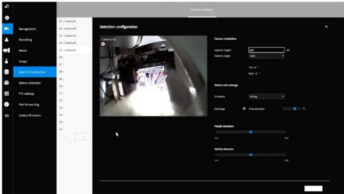
- Select a detection type: Intrusion detection, Line crossing detection, or Loitering detection.
- Click Select.
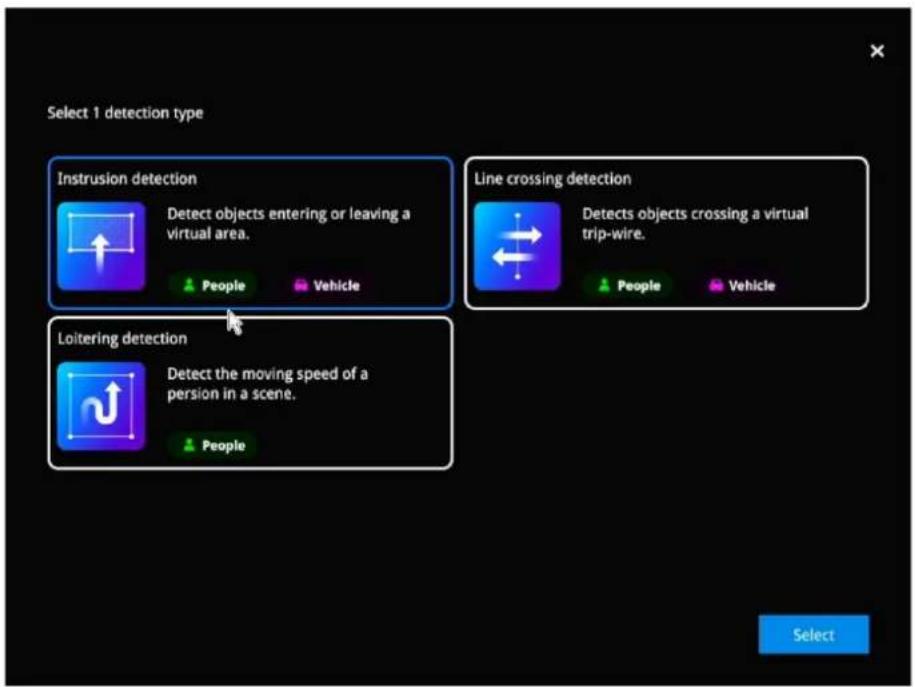
- Click and drag to draw a rectangular detection window.
When you are configuring a detection rule related to people detection (e.g., Intrusion, Loitering, or Line crossing), you cannot place a border point outside the People Detection area. Smart VCA invalidates any clicks outside the area.
The Detection area of fisheye camera running a Smart VCA package is shown below.
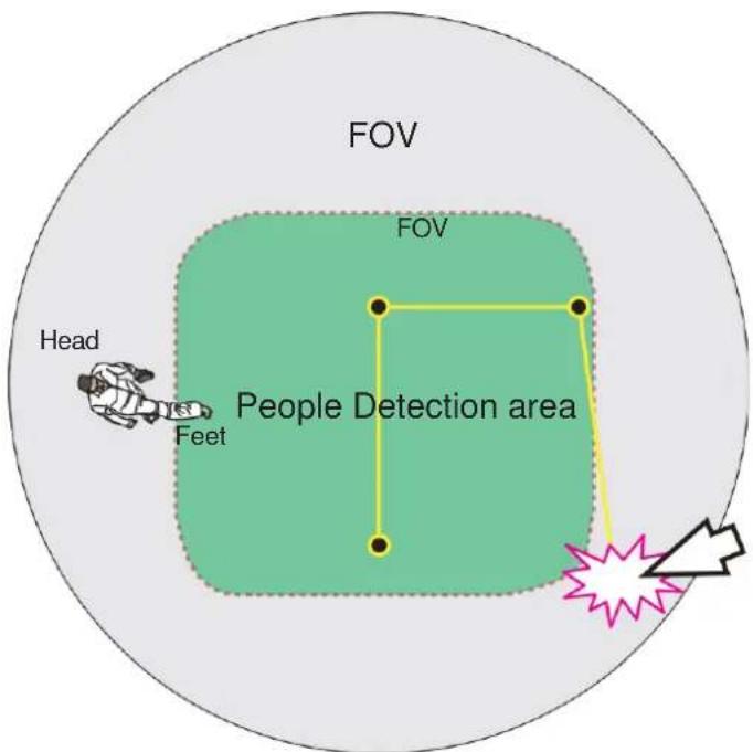
The Vehicle detection area is slightly different using a different object analysis algorithm.
For a fixed dome or bullet camera, a simulated floor level (People Detection area) is displayed on a Smart VCA configuration screen. The Smart VCA detection zones must be configured to have men walking through this area (their feet within the area).
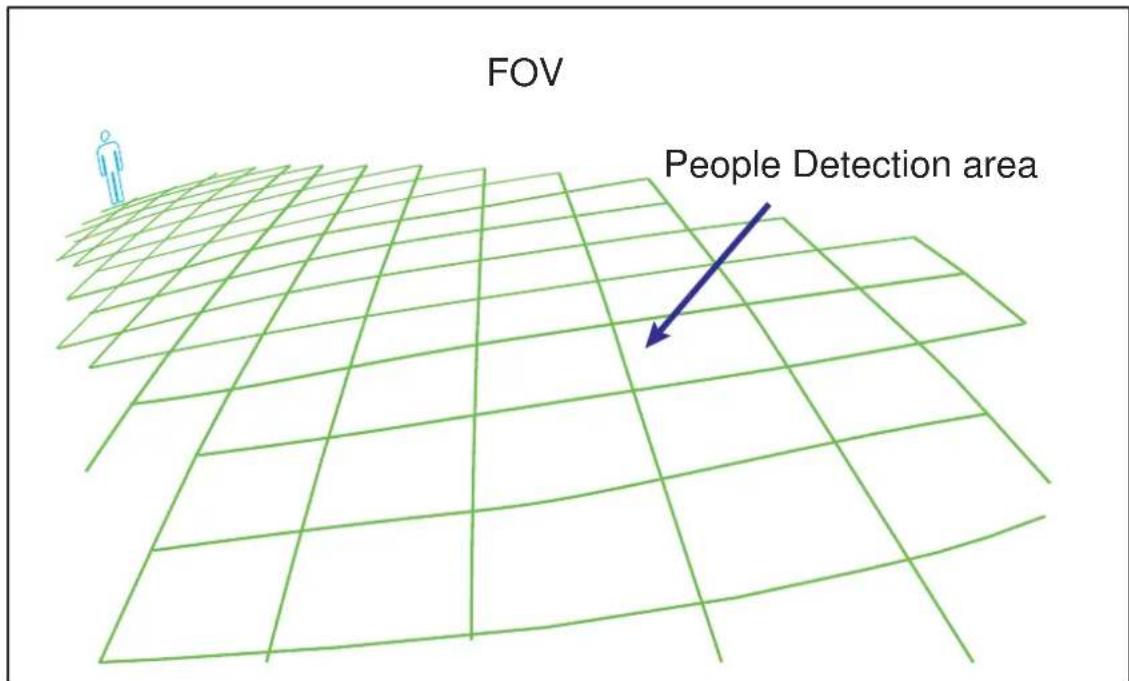
- Click the Apply button for the configuration to take effect.
3-5-7. Settings—Camera—Motion Detection
Motion Detection
To set up a detection window:
- Select a camera by a single click.
- Use the PTZ panel to move to a field of view where you want to place a detection window.
- Click and drag to draw a rectangular detection window.
- Pull the detection area level up to a preferred position. An object must be larger than the detection area to trigger an alarm.
-
Select a Sensitivity level using the slide bar.
-
Click the Apply button for the configuration to take effect.
The sample screen shows a connection with a speed dome camera.
If you already configured Preset positions, expand its menu and click on the presets to move to a position.
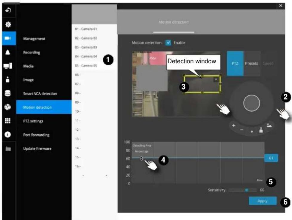
3-5-7. Settings - Camera - PTZ settings
To configure PTZ preset positions:
- Select a PTZ camera by a single click.
- Use the PTZ panel to move to a field of view where you want to designate as a preset position.
- Click the add button, and enter a name for the position. Press Enter to proceed. Repeat the configuration to create more positions.
- Click the Apply button for the configuration to take effect.
Note that the PTZ panel can vary with different PTZ cameras.
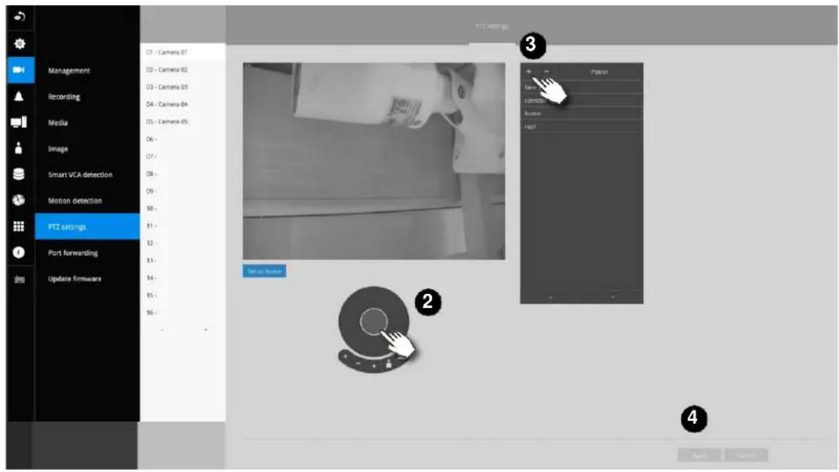
To configure a patrol:
- Click to enter the Patrol menu. Select a preset position if you want to change its position on the patrolling order.
- Click the up and down buttons to change the position on the order, or click the remove button to disband a position from the order. You can also change the interval to stay before moving from one position to the next position.
- Click the Apply button for the configuration to take effect.
- You may then click on the Preview patrol button to see if it runs as expected.
- Click on the Back to preset list button to return to the preset window.
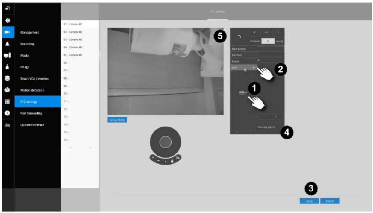
Fisheye camera has its unique options such as the mount types.
Please refer to page 188 or the camera's User Manual for fisheye display mode options.
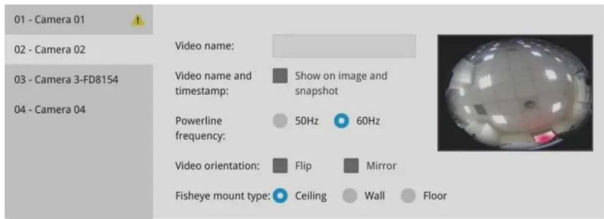
3-5-8. Settings - Camera - Port forwarding
You can associate an external port number to the cameras managed by the NVR. You can then configure the router, virtual server or firewall, so that the router can forward any data coming into a pre-configured port number to a network camera on the private network, and allow data from the camera to be transmitted to the outside of the network over the same path.
| From | Forward to |
| 122.146.57.120:8000 | 192.168.2.10:80 |
| 122.146.57.120:8001 | 192.168.2.11:80 |
| ... | ... |
When properly configured, you can access a camera behind the router using the HTTP request such as: http://122.146.57.120:61001
If you change the port numbers on the Network configuration page, please open the ports accordingly on your router. For example, you can open a management session to your router to configure access through the router to the camera within your local network. Please consult your network administrator for router configuration if you have troubles with the configuration.
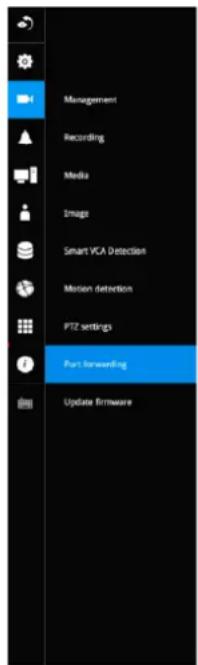
Port forwarding
| Device | Camers IP | External port |
| 01 - Camera 01 | 169.254.9.108 | 61001 |
| 02 - Camera 02 | 169.254.8.92 | 61002 |
| 03 - Camera 03 | 192.168.51.57 | 61003 |
| 04 - Camera 04 | 169.254.8.51 | 61004 |
| 05 - Camera 05 | 169.254.8.207 | 61005 |
| 06 - | - | |
| 07 - | - | |
| 08 - | - | |
| 09 - | - | |
| 10 - | - | |
| 11 - | - | |
| 12 - | - | |
| 13 - | - | |
| 14 - | - | |
| 15 - | - | |
| 16 - | - |
NOTE:
- This port forwarding feature does not support legacy cameras connected via the RTSP method.
- The configurable range of port numbers is between 61001 \~ 61128.
3-5-9. Settings - Camera - Update firmware
Prepare the camera firmware files in a USB thumb drive. Connect the thumb drive to the NVR's USB port.
Select a camera, and click the upload button.
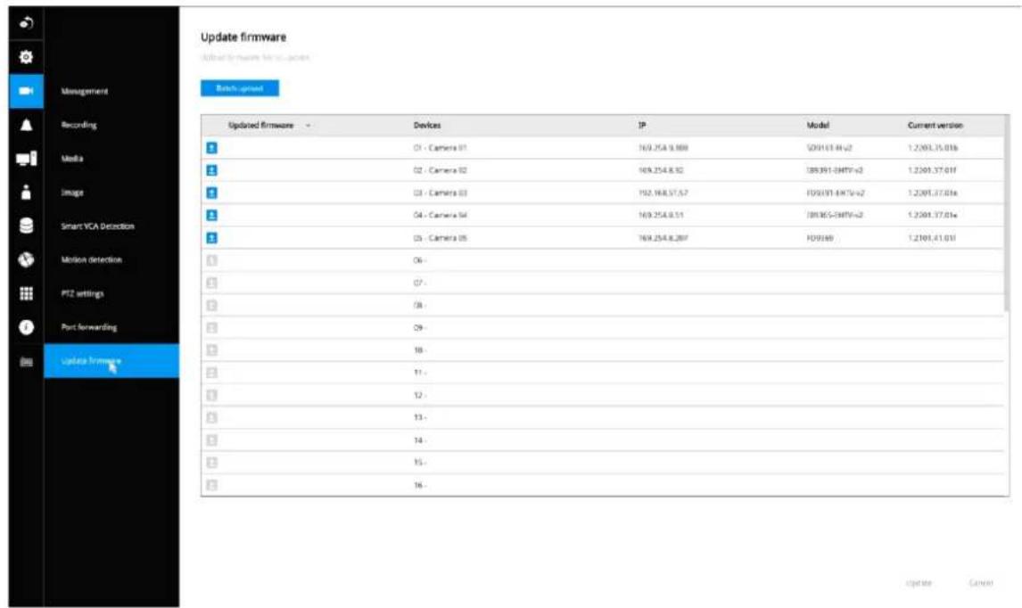
An upload panel will appear. Select the firmware file. Click the Upload button.
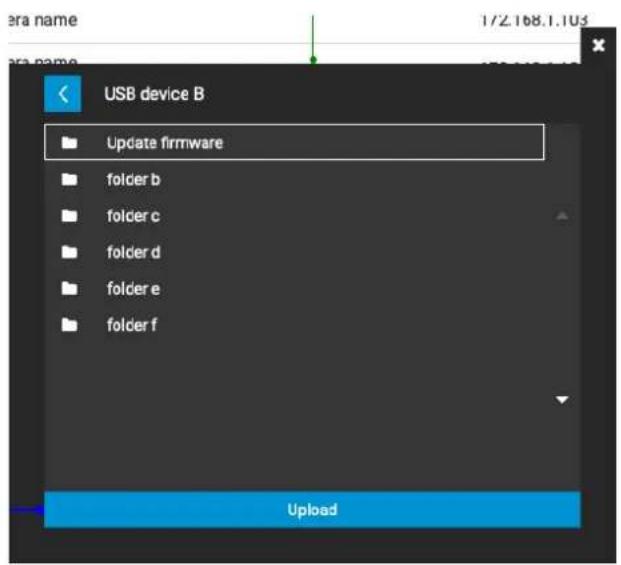
The Batch upload function allows you to update the firmware of multiple cameras. The firmware update can take place on up to 8 cameras at a time. The Waiting... message will display for cameras that are waiting for the update to take place.
Different messages can appear with different update results.
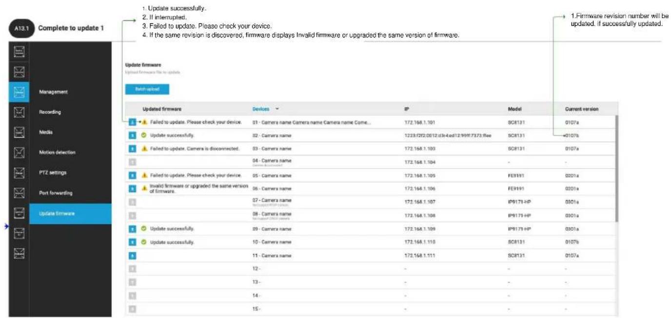
3-5-10. Settings—Alarm—Alarm
The events reported from individual cameras' digital inputs, digital outputs, and motion detection can be accommodated in the NVR system's alarm settings. These events will then be reported or trigger corresponding actions as follows:
- Record the video by the time the event is triggered.
- Reporting events via Email with snapshots attached.
- Sound the onboard buzzer.
- Triggering video snapshot and text message by the occurrences of events to an FTP site.
- Triggering a camera's DO.
- Triggering a PTZ camera(s) for its lens to move to a preset position.
- Sending notification to the VSS CMS software.
- Sending a full screen live view on the connected monitor.
You can create up to 10 instances of alarm.
Hardware connections to DIs or DOs, e.g., window sensors, should be made separately. The motion detection configuration can be made in the Camera configuration window.
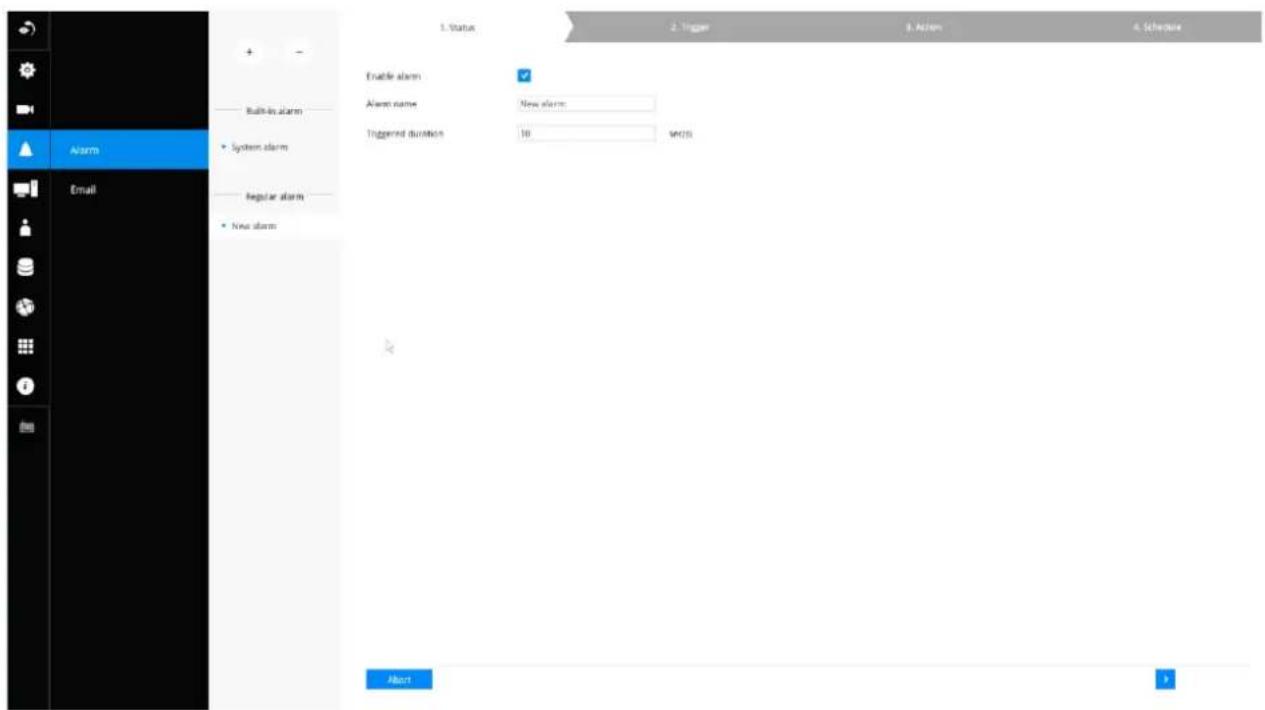
When an alarm is triggered, a message prompt will appear on the Live view or any configuration window.
14:14
2018.02.22

GPS
Below is a glimpse of alarm sources and alarm actions:
| Sources | Actions | ||
| System DI | Video recording | ►video footage | |
| System DO | Send Email | ►snapshots | |
| Fan failure | Buzzer | ||
| PoE error | ► | FTP | ►snapshots |
| Disk failure | Camera DO | ||
| Disk full | Pan-tilt-zoom | ►Pan-Tilt-Zoom | |
| Brute force attack | System DO | ||
| Full occupancy reached | Send to CMS | ||
| Full occupancy clear | |||
| - Camera sources below | Send video to full screen | ||
| Camera DI | VIVOCloud app notification | ||
| Camera DO | HTTP | ||
| Motion detection | |||
| PIR | |||
| Tampering detection | |||
| Camera disconnected | |||
| Line crossing detection | |||
| Intrusion detection | |||
| Loitering detection | |||
| Face detection | * Camera DI/DO, motion detection, and tampering are not supported for ONVIF cameras. | ||
| Missing object detection | |||
| Unattended object detection | |||
| Quarantine vent | |||
| Cyber attack | |||
| Video loss | |||
| RAID degrade | |||
To create an alarm,
- Click on the Add button

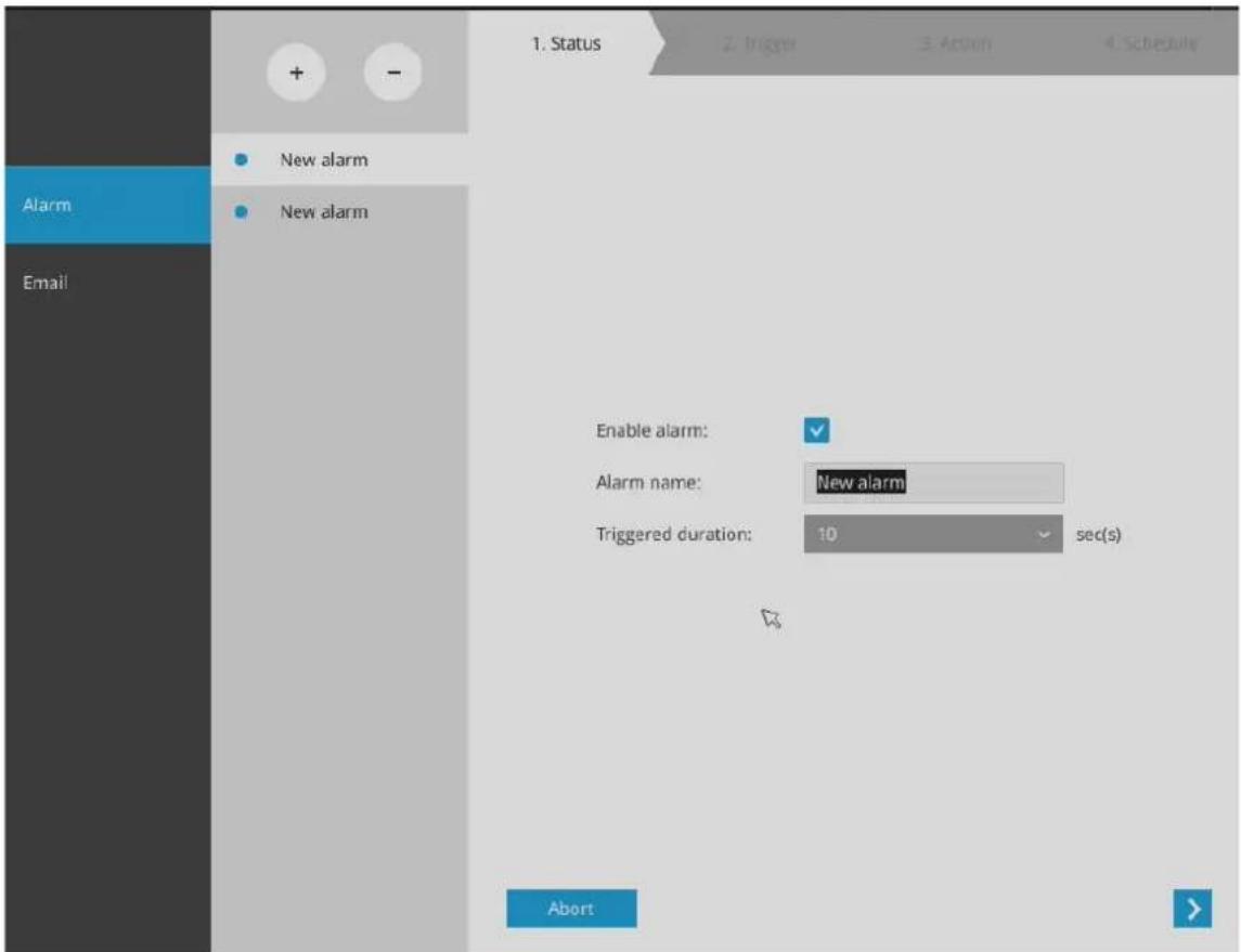
You can manually enter a name for the current setting. You can enter up to 16 numeric or alphabetic characters for the name, including symbols such as [0-9][a-z][A-Z][_]. You can also designate the interval between one alarm and the next triggered alarm to avoid the situation that the alarms can be too frequently triggered.
Click on the next button to proceed.
Please note that on a fisheye camera's Motion window, you can click and move the corner marks of a window to change its shape. The Motion window does not have to be a square.
- On the Trigger window, select system triggering conditions, or one or more cameras by selecting their checkboxes. The number of DI or DOs on each camera is automatically detected and displayed through individual checkboxes. The Motion detection function, if there are many detection windows configured on a camera, is all triggered by one checkbox.
Note that the triggering sources will be listed even if the camera is currently not connected.
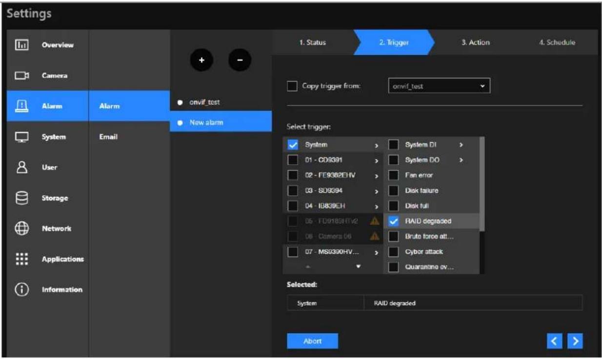
![Settings Overview Camera Alarm System User Storage Network Applications Information + - onvif_test New alarm 1. Status 2. Trigger 3. Action 4. Schedule Copy trigger from: onvif_test Select trigger: System > Camera DI > 01 - CD9391 > Camera DO > 02 - FE9382EHV > Motion detection 03 - SD9394 > PIR 04 - IB830EH > Tampering det... 05 - FD9189HTV2 > Camera disco... 06 - Camera OS > Video loss [Mid] 07 - MS9390HV... > Brute force alt... Selected: Abort Selected:](/content/2026/05/894040/images/ce8eddbcb30f491f85e2a3ec86d6aa36dc4f4fb8253a1c0cf1a8c9ad8b501953.jpg)
You can also find the "RAID degraded" option, which can be triggered when RAID is corrupted or undetected. In addition, the "Video loss (for video server only)" option (see the above red box) will be available if connecting to a video server.
You may also select the "Copy trigger from" menu to borrow the setting you previously configured.
Click on the next button to proceed.
- On the Action window, you can select the Action type from a drop-down menu. The configuration details of each action type is discussed below.
4-1. Recording—When an event is triggered, the selected camera will record a video footage of the length defined by the pre-/post-event setting, to the NVR system.
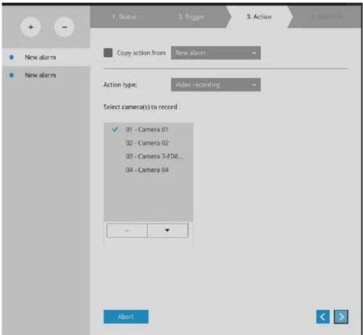
4-2. Email—The Email action sends an Email to the administrator along with a snapshot of the event.
To configure Email notification, enter valid Email addresses as the Sender and Recipient addresses, an Email subject, and the SMTP server address through which the Email will be delivered. If you need to log in to SMTP server to deliver an Email, enter the User name and password for access to that account.
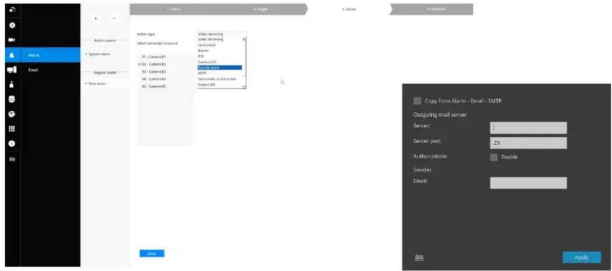
The Email subject and addresses can be composed of 254 characters in numeric or alphabetic characters including: [0-9][a-z][A-Z][_][[-][.][,][@]. You can enter the addresses of multiple recipients. Use semicolons, (;), to separate the addresses of multiple recipients.
4-3. Buzzer - The buzzer is sounded on the occurrence of the event. The buzzer tones are categorized into: Critical (1 long, 1 sec interval) Major (1 long 2 shorts, 1 sec interval), Normal (3 shorts, 2 sec interval), Minor (2 shorts, 2 sec interval), and Notify (2 very shorts) depending on the importance of an event. Select a Buzzer modulation from the drop-down list.
A long tone has a duration of 1 second, while a short tone 0.5 second. A very short tone lasts only for 0.1 second.
Select how many times the buzzer tones will be repeated on the occurrence of an event.
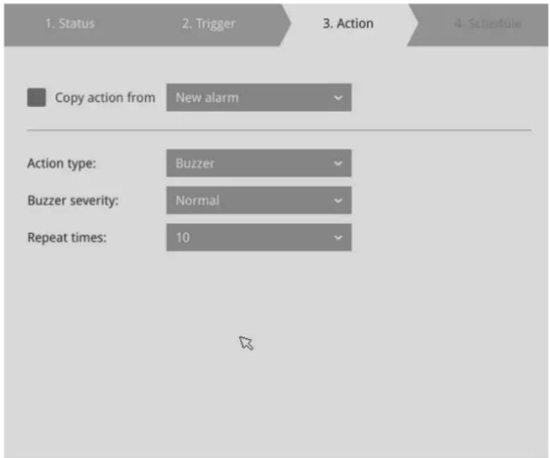
If events of different importance are issued at the same time, e.g., one major and one minor event, system will ignore the minor event and sound the buzzer tone for the major event only. The buzzer can be sounded either by the Alarm actions or the system events. If Alarm actions and system service events occur at the time, Alarm actions have the higher priority.
If multiple Alarm actions occur, the currently-sounded events can be depleted by the new event.
There are conditions that the system will sound the buzzer, and the conditions are not configurable.
- Disk failure - missing drives or SMART detected failures.
- Disk full - the free space is too small for recording tasks.
4-4. FTP-Snapshots from specified cameras can be uploaded to an FTP site on the occurrence of an event. Enter the FTP site address in the dotted-decimal notation, e.g., 159.22.151.20. Enter the login name and password for the user account. You can enter a directory name you prefer on the FTP site. The server port default is 21, a different number between 1025 and 65535 can also be assigned.
The snapshot thus delivered has a size of 320x240 pixels. If authentication is not applied, login will proceed using the [anonymous] account.
The file names of the snapshot jpeg files will look like this: [MAC]_[DATE]_[TIME]_[CAMERA_INDEX].jpg - If similar files already exist, an additional index number will be added to the end of file name.
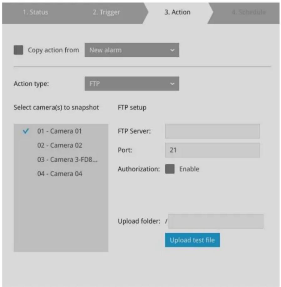
4-5. Camera DO - A triggered alarm triggers a camera's DO, e.g., an alarm siren.
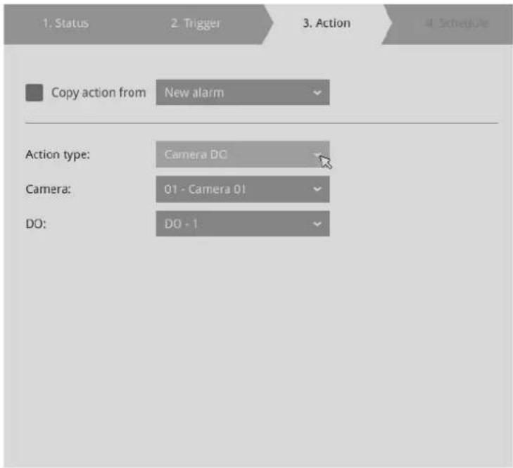
4-6. Camera pan-tilt-zoom - A PTZ capable camera can move its lens to the preset position in case of a triggered alarm. For example, a triggered sensor may indicate an area of interest has been intruded, and a camera's field of view should be moved to cover that area. The precondition is that you properly set up preset positions on your PTZ cameras using a local or a web console.
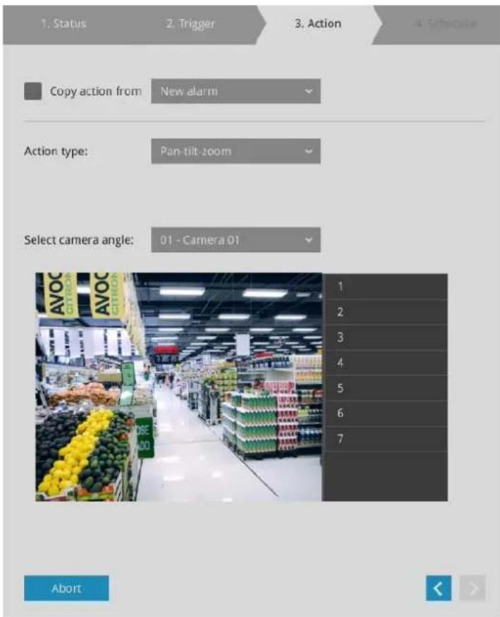
4-7. System DO - A triggered alarm can be used to toggle the NVR's digital output, e.g., to sound an alarm siren.
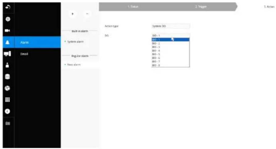
4-8. VIVOCloud app notification - A triggered alarm can be used to toggle an event notification to the VIVOCloud utility. You will then be able to receive event notifications from your cell phone.
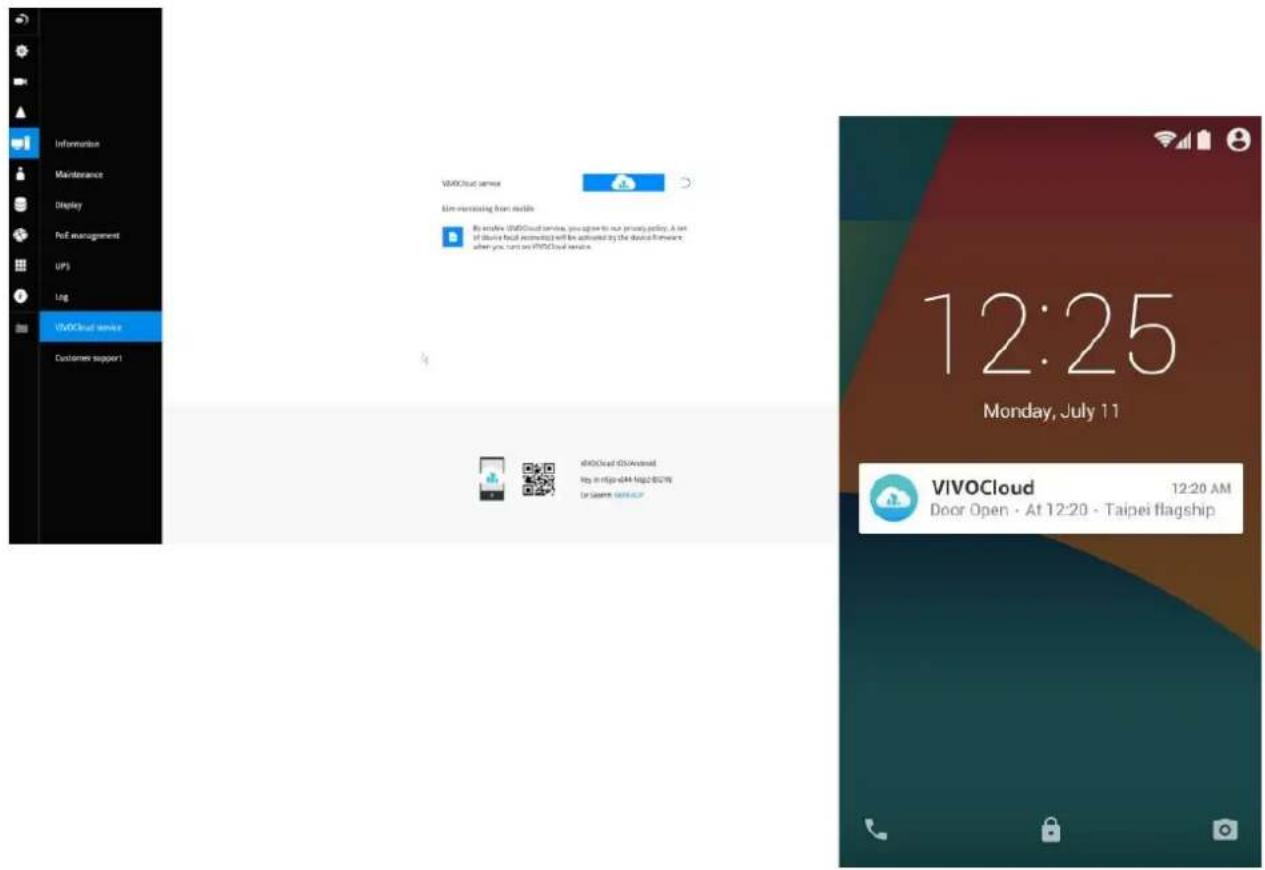
4-9. Send to CMS—An event message will display on your VSS CMS software in the event of GPS signal loss or G-sensor force exceeds configured thresholds.
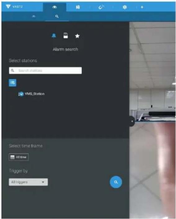
The triggered alarms can be found in the Alarm search panel.
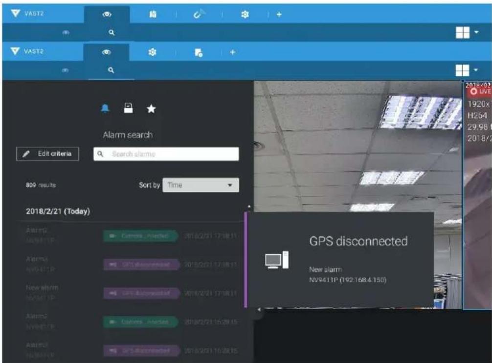
You should also configure a corresponding alarm on the VSS server. Enter the Alarm management window. Select System Event and begin your configuration.
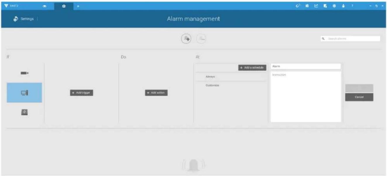
Select NVR and a triggering condition, such as the GPS disconnect, as your trigger.
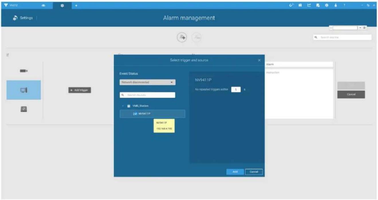
Select the triggering condition from the pull-down menu.
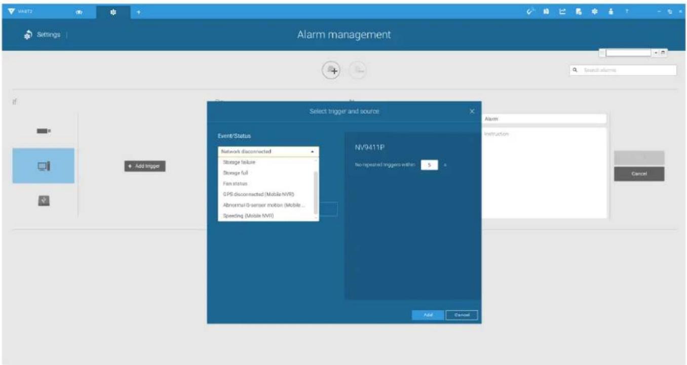
Configure the corresponding action, and proceed with the rest of the configuration. When an event is triggered, such as GPS signal loss, or exceptional G-force is detected, an event message will prompt on screen. You can also search the past alarms to find an event.
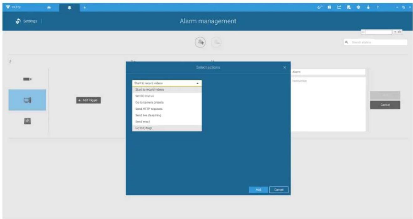
4-10. Send video to full screen—The video feed from a related camera will be displayed on the occurrence of a triggered condition.
5. On the Schedule page, you can select to activate or de-activate alarm triggers throughout a specific timeline. For example, in some situations you can disable the alarm triggers during the office hours, and choose to enable the triggers only during the off-office hours.
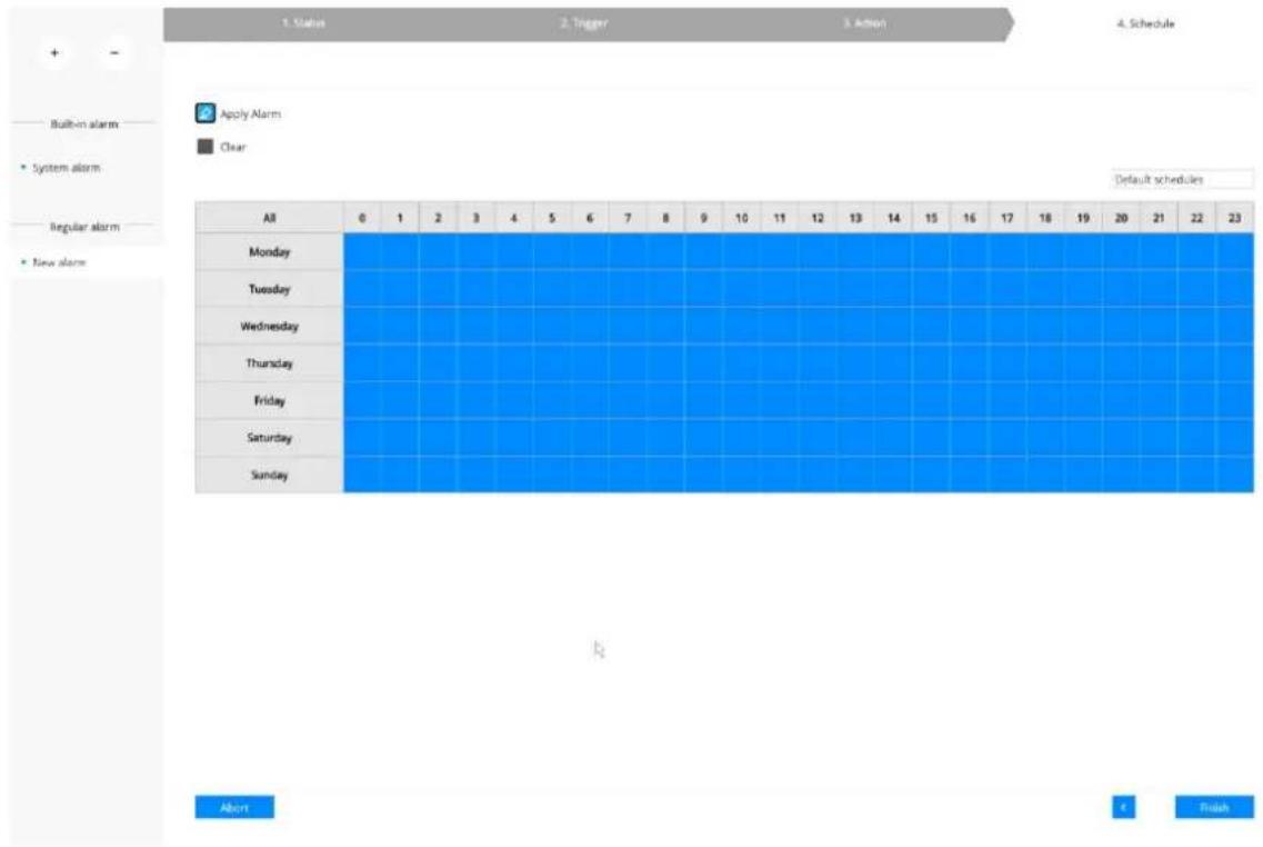
- Click Finish to end the configuration.
- Repeat the process above to create more alarms according to the needs in your surveillance deployment.
3-5-11. Settings - Alarm - Email
This window provides an interface where you can configure the connection to a Mail server. Via the Mail server, the system can deliver Emails containing system alarm messages to multiple receivers. A reachable Mail server and Email accounts must be provided before you can apply the settings.
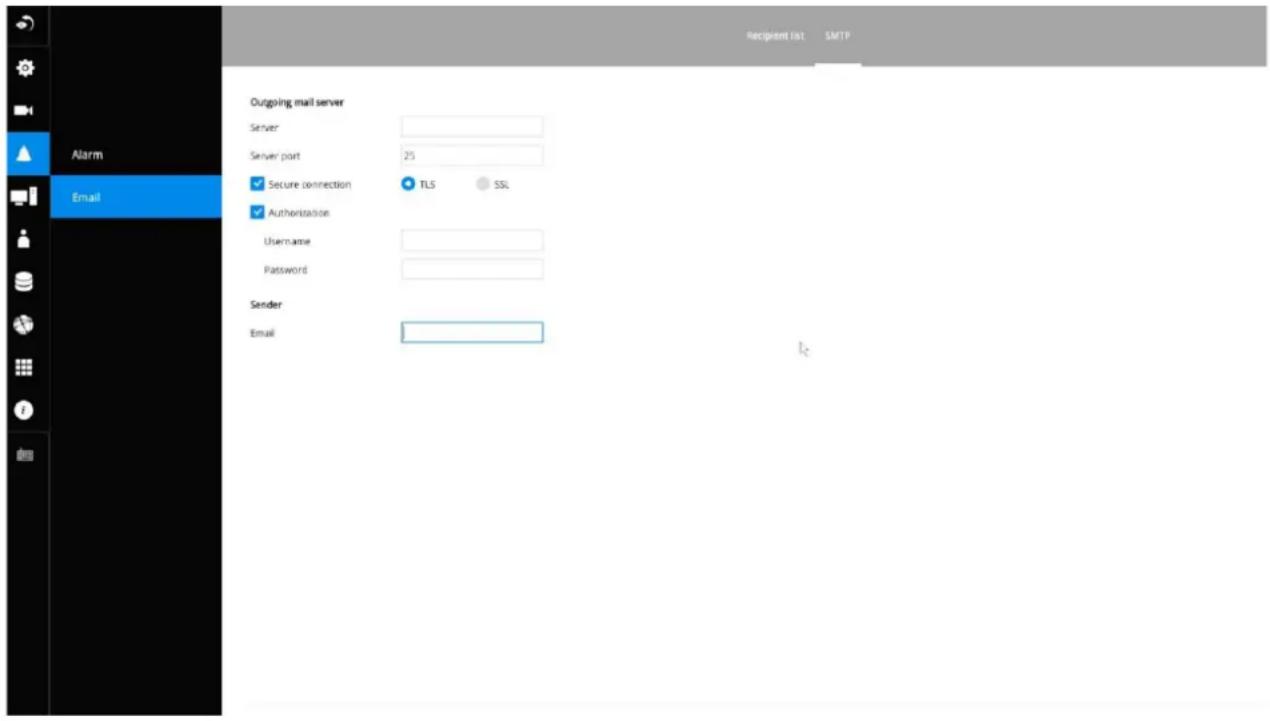
The configuration options are identical to those found in the Email configuration in Settings - Alarm window.
3-5-12. Settings—System—Information
On this window, you can configure the following:
- Change the system name. Using a name in different languages is supported via a web console.
- Select the UI text language.
- Configure system time, time zone, and if you are connected to a DNS server where Auto Daylight Saving time can be applied, you can acquire the associated setting from a server within your network. You can use the Auto Setup button to automatically update the daylight saving configuration. A system reboot is required.
You can also manually update the daylight saving profile in the GZ format using the Import file button below.
- Click the Apply button for the configuration to take effect.
Note that if NTP time server configuration (Auto) is preferred, the system will automatically configure all cameras to be listening to the system, and therefore to the same time server.
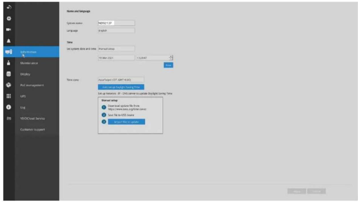

IMPORTANT:
Changing system time can produce disruptions to the existing recordings. Turning the current system time back to a time when video recording was taking place can generate duplicate files. And those files may not be playable.
3-5-13. Settings–System–Maintenance
If the need arises for updating system firmware, acquire the update from VIVOTEK's technical support or download site. Locate the firmware binaries, and click the Import button. The upgrade should take several minutes to complete. Note that during the upgrade, the recording task will be interrupted. A system reboot will ensure whether an update is successful or not.
On this window, you can perform 4 maintenance tasks:
- Update firmware—Download firmware and save it to a USB drive in the FAT format, attach the USB device to the NVR for firmware upgrade.
- Update device pack—A device pack allows you to import associated configurations and parameters for new camera models so that these cameras can be integrated into your NVR configuration. The information in the device pack is related to some tunable parameters.
- Backup-You can back up your system configuration using the Backup function. Click Backup, a message window will prompt. Click Save to preserve your system configurations.
Select a location for your backup file, then click Save to complete the process. If you back up to a USB thumb drive, that thumb drive must be formatted using the FAT format.
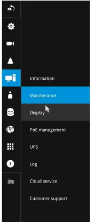
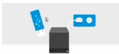
flowchart
graph TD
    A["Mobile Device"] -->|Send| B["Server"]
    C["Email Icon"] --> B
    D["User Interface Icon"] --> B
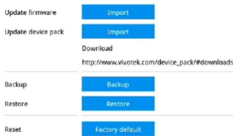
Note that the backup action does not involve the following:
- Recorded videos and database,
-
Alarm records, bookmarks, and bookmarked footages.
-
Restore—If you have a previously-saved profile, you can restore your previous configuration. Click the Restore button.
A file location window will prompt. Locate the backup file, and click Open. The Restore process will take several minutes to complete, and system operation will be interrupted during the process.
- Restore to factory default—Restores the NVR to its factory default status by deleting all data and configuration files on HDDs.
3-5-14. Settings - System - Display
On this page, you can configure the system to consecutively display (rotate) cameras' view cells on the Live view window. For example, if you have 8 cameras in 2 2x2 layouts, the rotation can let you see the live views of all cameras by every few seconds.
If you have a 4K monitor, select the display resolution to 3840 x 2160.
You can also enable or disable the Alarm notification.
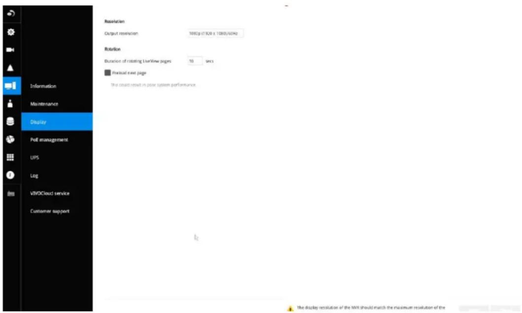
To enable the rotate function, click on the rotate button on the layout panel.
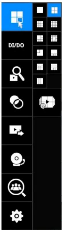
3-5-15. Settings - System - PoE management
When IP cameras are connected to the NVR's PoE ports, their power consumption is constantly monitored, and the power budget is displayed on the PoE management screen.
The following apply to the PoE connections and PoE management:
- The total power budget is:
50W
- Cameras will be automatically enlisted to the NVR. The PoE connection status is polled every 10 seconds.
- The maximum output for each port is 30W. If you attach a camera with a very high power demands, e.g., a speed dome with IR lights on, PoE power will simply be disabled on that port.
- PoE Plug and Play takes effect after the initial setup. Any cameras connected thereafter will automatically join the NVR configuration. If you manually delete a camera from list, you should unplug and then re-connect it to the PoE port before joining the network back to NVR.
- The above does not apply to ONVIF cameras.
- For devices that come with multiple video channels, e.g., a video server, each video stream will occupy a video channel.
- You can manually enable or disable the PoE output on each port.
- If port #1, #3, and #4 are connected to powered devices, and power runs short on the NVR. The ports with smaller port number, e.g., port #1, will be powered first. The ports with a larger port number will be disconnected first. In this case, port #4 will be disconnected.

23 / 200 W
| Port | Name | Power used (Welt) | PO-Class | |
| CP | 1 | - | 0.0 | 5 |
| CP | 2 | Camera 01 | 9.2 | 4 |
| CP | 3 | - | 0.0 | 5 |
| CP | 4 | Camera 02 | 5.5 | 4 |
| CP | 5 | - | 0.0 | 5 |
| CP | 6 | Camera 04 | 6.4 | 4 |
| CP | 7 | - | 0.0 | 5 |
| CP | 8 | Camera 05 | 2.1 | 2 |
| CP | 9 | - | 0.0 | 5 |
| CP | 10 | - | 0.0 | 5 |
| CP | 11 | - | 0.0 | 5 |
| CP | 12 | - | 0.0 | 5 |
| CP | 13 | - | 0.0 | 5 |
| CP | 14 | - | 0.0 | 5 |
| CP | 15 | - | 0.0 | 5 |
| CP | 16 | - | 0.0 | 5 |
Apply Cancer
-
The PoE automatic enlistment does not apply for cameras that come with preset credentials, namely, password-protected.
-
The PoE port status can reflect the following situations:
A. PoE enable -PoE is working (port icon displayed in green on the upper-right screen)
B. PoE turned OFF –PoE manually disabled (turned to OFF)
C. PoE turned OFF -Port power overload (under camera name)
D. PoE turned OFF – Total power overload (under camera name)
E. PoE turned OFF -Abnormal power supply voltage(under camera name)
F. PoE turned OFF –Non-standard powered device (under camera name)
G. PoE turned OFF -Port error (under camera name)
The UI text on PoE power consumption will turn red if the total power budget is exceeded. A warning event message will be delivered as push notification or via email.
- When the NVR has little reserved power budget, and you attach a new camera, the NVR will stop supplying power to the new camera.
3-5-16. Settings - System - UPS
On this page, you can configure the system to gracefully shut down when UPS battery is lower than a certain level. You may also let it shut down when the estimated sustainable time is reached. We support APC Black 500 UPS.
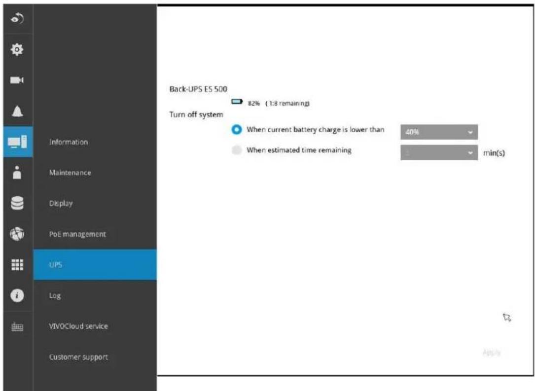
3-5-17. Settings - System - Log
System logs are categorized as System, Recording, User, and Error.
To display system logs, select a range of time and click on the Search button.
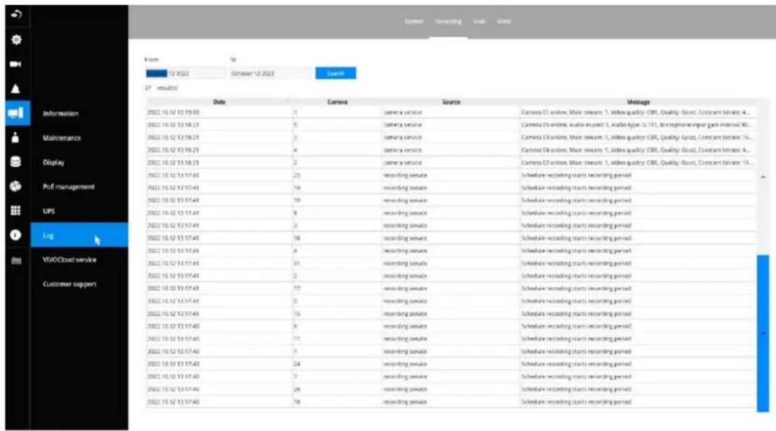
You can search for past logs in each category window.
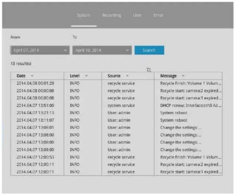
| Date | Camera | Source | Message |
| 2014.04.10 16:27:25 | 1 | recording service | Recording stop: RTSP Fail |
| 2014.04.10 16:03:30 | 4 | camera service | Camera online |
| 2014.04.10 16:03:28 | 4 | camera service | Camera offline |
| 2014.04.10 16:02:23 | 4 | camera service | Camera offline |
| 2014.04.10 16:02:04 | 4 | recording service | Recording stop: RTSP Fail |
| 2014.04.10 15:59:08 | 4 | camera service | Camera online |
| 2014.04.10 15:59:04 | 4 | camera service | Camera offline |
| 2014.04.10 15:57:53 | 6 | camera service | Camera online |
| 2014.04.10 15:57:07 | 6 | camera service | Camera offline |
| 2014.04.10 15:56:55 | 6 | recording service | Recording stop: RTSP Fail |
| 2014.04.10 15:56:42 | 4 | camera service | Camera offline |
| 2014.04.10 15:56:40 | 4 | recording service | Recording stop: RTSP Fail |
| 2014.04.10 15:56:34 | 4 | recording service | Recording stop: RTSP Fail |
| 2014.04.10 15:56:16 | 4 | recording service | Recording stop: RTSP Fail |
| 2014.04.10 11:19:22 | 1 | camera service | Camera online |
| 2014.04.10 11:19:08 | 1 | camera service | Camera offline |
| Date | Message type | Message |
| 2018.11.13 14:35:01 | Security rule | [Trend Micro]: 1 s.1133810, 2016/11/13 14:35:0, 192.168.5.107:42930 > 192.168.5.122:80, 192.168.5.107, Victim |
| 2018.11.13 14:25:32 | Security rule | [Trend Micro]: 0 s.1133810, 2016/11/13 14:25:31, 192.168.5.107:40378 > 192.168.5.122:80, 192.168.5.107, Victim |
| 2018.11.13 13:49:04 | Security rule | [Trend Micro]: 15 s.1133810, 2016/11/13 13:49:3, 192.168.5.107:30147 > 192.168.5.122:80, 192.168.5.107, Victim |
| 2018.11.13 13:49:00 | Security rule | [Trend Micro]: 14 s.1133810, 2018/11/13 13:49:59, 192.168.5.107:30137 > 192.168.5.122:80, 192.168.5.107, Victim |
| 2018.11.13 13:49:00 | Security rule | [Trend Micro]: 13 s.1133810, 2018/11/13 13:48:59, 192.168.5.107:30133 > 192.168.5.122:80, 192.168.5.107, Victim |
| 2018.11.13 13:49:00 | Security rule | [Trend Micro]: 12 s.1133810, 2018/11/13 13:48:59, 192.168.5.107:30132 > 192.168.5.122:80, 192.168.5.107, Victim |
| 2018.11.13 13:49:00 | Security rule | [Trend Micro]: 11 s.1133810, 2018/11/13 13:48:59, 192.168.5.107:30130 > 192.168.5.122:80, 192.168.5.107, Victim |
| 2018.11.13 13:48:56 | Security rule | [Trend Micro]: 10 s.1133810, 2018/11/13 13:48:55, 192.168.5.107:30129 > 192.168.5.122:80, 192.168.5.107, Victim |
| 2018.11.13 13:48:56 | Security rule | [Trend Micro]: 9 s.1133810, 2018/11/13 13:48:55, 192.168.5.107:30126 > 192.168.5.122:80, 192.168.5.107, Victim |
| 2018.11.13 13:48:56 | Security rule | [Trend Micro]: 8 s.1133810, 2018/11/13 13:48:55, 192.168.5.107:30125 > 192.168.5.122:80, 192.168.5.107, Victim |
| 2018.11.13 13:48:56 | Security rule | [Trend Micro]: 7 s.1133810, 2018/11/13 13:48:55, 192.168.5.107:30124 > 192.168.5.122:80, 192.168.5.107, Victim |
| 2018.11.13 13:48:56 | Security rule | [Trend Micro]: 6 s.1133810, 2018/11/13 13:48:55, 192.168.5.107:30123 > 192.168.5.122:80, 192.168.5.107, Victim |
| 2018.11.13 13:48:56 | Security rule | [Trend Micro]: 5 s.1133810, 2018/11/13 13:48:55, 192.168.5.107:30116 > 192.168.5.122:80, 192.168.5.107, Victim |
| 2018.11.13 13:48:56 | Security rule | [Trend Micro]: 4 s.1133810, 2018/11/13 13:48:55, 192.168.5.107:30120 > 192.168.5.122:80, 192.168.5.107, Victim |
| 2018.11.13 13:48:56 | Security rule | [Trend Micro]: 3 s.1133810, 2018/11/13 13:48:55, 192.168.5.107:30118 > 192.168.5.122:80, 192.168.5.107, Victim |
| 2018.11.13 13:48:56 | Security rule | [Trend Micro]: 2 s.1133810, 2018/11/13 13:48:55, 192.168.5.107:30105 > 192.168.5.122:80, 192.168.5.107, Victim |
| 2018.11.13 13:48:56 | Security rule | [Trend Micro]: 1 s.1133810, 2018/11/13 13:48:55, 192.168.5.107:30097 > 192.168.5.122:80, 192.168.5.107, Victim |
| 2018.11.13 13:48:52 | Security rule | [Trend Micro]: 0 s.1133810, 2018/11/13 13:48:51, 192.168.5.107:30086 > 192.168.5.122:80, 192.168.5.107, Victim |
3-5-18. Settings - System - Cloud service
This window provides access to the cloud service configuration. Please refer to page 30 for how to configure system access using the VORTEX Connect functionality.
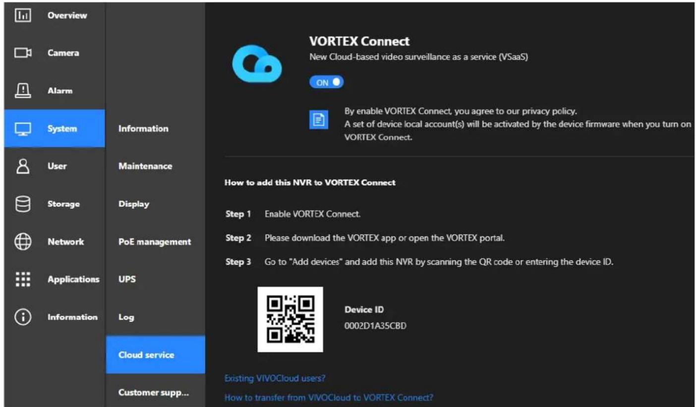
3-5-19. Settings – System - Customer support
If users encounter problems with the system, they could export a debug report and send it to VIVOTEK's technical support.
With an Internet connection, users can also open the Remote access functionality. An access ID will be generated. They can send the ID to VIVOTEK's technical support for the support to remotely examine system configuration and errors. Note that you should only allow remote access when you need the technical support to access and diagnose system errors. There is a 60 second initial timeout when trying to connect to the cloud server.
The remote access will automatically be disabled after 14 days if it is not manually disabled after the debug. You should not disable the remote access while the debug process is taking place.
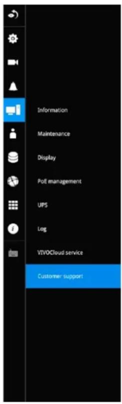
Customer support includes log generation tool and remote access, allowing VIVOTEK technical support engineers to quickly view, diagnose, and resolve technical issues on your NVR.
Notices.
-
Enable remote access only when you are being asked by VIVOTEK technical support engineers.
-
Provide debate hugs, access ID alone with NVR account and password only to VIVOTE's technical support enquirers.
-
Remote access will be automatically disabled after 14 days.
Debug logs

Remote access

Access ID
9Dby99cuiNE+MxXYC6Vx3PvkVDXMvrFIjZOM3FMi/DA=
Expired on 10.26.2022
Ready to connect
If a network unavailable message is displayed at the lower screen, the network connection between NVR and cloud server may have failed.
3-5-20. Settings-User
The User window allows you to create more users, to change user password, and place limitations on users' privileges and administration rights. Up to 16 users can be created, including the default administrator.
- By default, there are two user groups: Administrator and Regular user.
- The regular users cannot access the Settings window, meaning that regular users can not add or remove cameras, make changes to alarm, network, and all other system settings. When users try to access the Settings window, the login window prohibits regular users to log in. There is simply no regular user's name on the login window.
- The administrator users can access all cameras recruited in the configuration, while the regular users can be configured to have access to some or all cameras.
- The system blocks out the video feeds from users who are denied the access to particular cameras. The alarms and the alarm-triggered recordings from those cameras will also be inaccessible for unauthorized users.
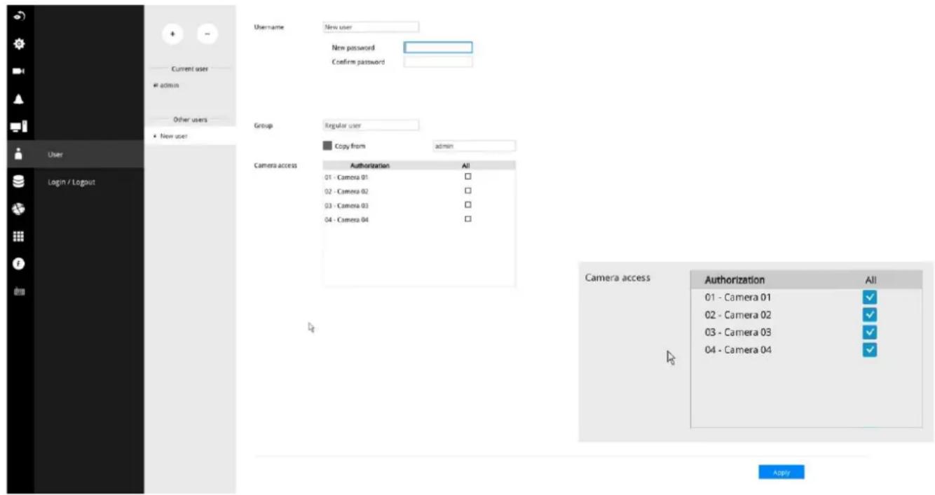

IMPORTANT:
The default administrator name and password are admin and admin. It is highly recommended to change the default password to prevent unauthorized access to the system.
To create or edit users,
- Select a User group by unfolding its pull-down menu. Select either an Administrator or regular user as the user group.
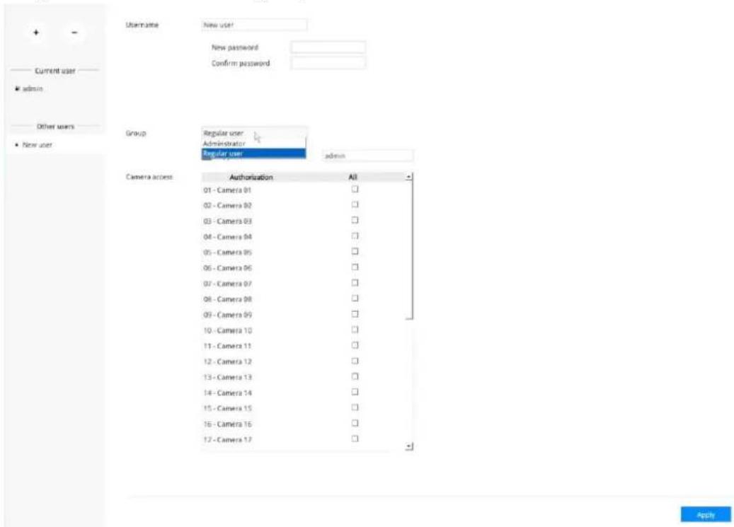
- Enter the Username and password. The max. number of characters for a user name is 64, with alphabetic and numeric characters including [0-9][a-z][A-Z][_][[-][.][,][@]. The max. number for password is also 64.
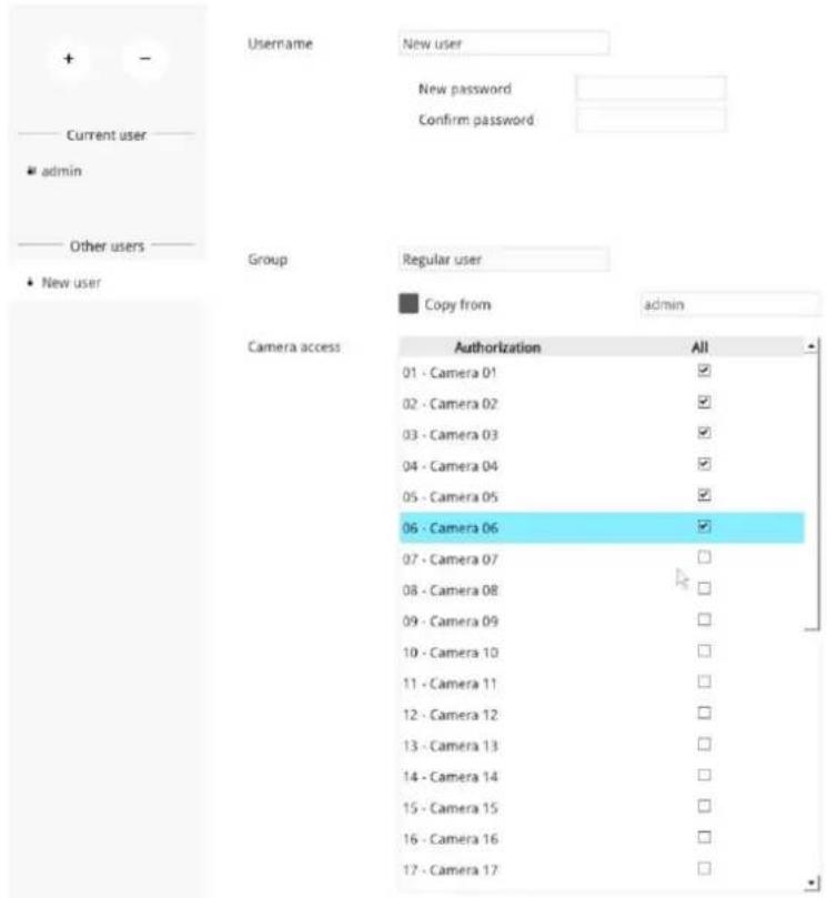
- If you are creating a regular user with limited access to cameras, deselect the checkboxes by the cameras to deny the user access.
- Click Apply to close the configuration window. Repeat the process to create more users.
3-5-21. Settings-User-Login / Logout
Login
- Login required to view live streaming: If selected, users will be required to enter his/her credentials before displaying a live view. If not selected, the NVR displays live view first. Login will be required when performing specific tasks, such as entering the Settings page.
Auto Logout should also be enabled when the NVR can be left unattended for an extended period of time. Default is 10 minutes.
Camera views will be available for users according to their privilege settings as designated in the User account configuration. Some camera views will be available for some users, while others are not.
- Move authorized cameras to the beginning of live view (regular users only): For users who have access to specific cameras only, he will be required to enter his credentials before viewing a live view.
Logout
- Enable auto logout: By default, a user is logged out automatically after being idle for 10 minutes. If not selected, the NVR will not log out automatically. A user can only log out manually.
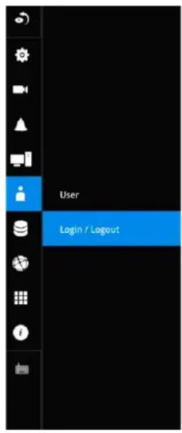
Login
√ Login required to view live streaming
√ Move authorized cameras to the beginning of liveview(regular users only)
Logout
√ Enable auto logout
3-5-22. Settings-Storage
The storage page displays the volume information including physical position, total capacity, used and free space, and associated commands such as Format and Delete. Since each volume contains only 1 hard drive, detailed information about the hard drive is also displayed on this page.
You can format an existing storage volume in situations such as when you need to re-deploy the system elsewhere.
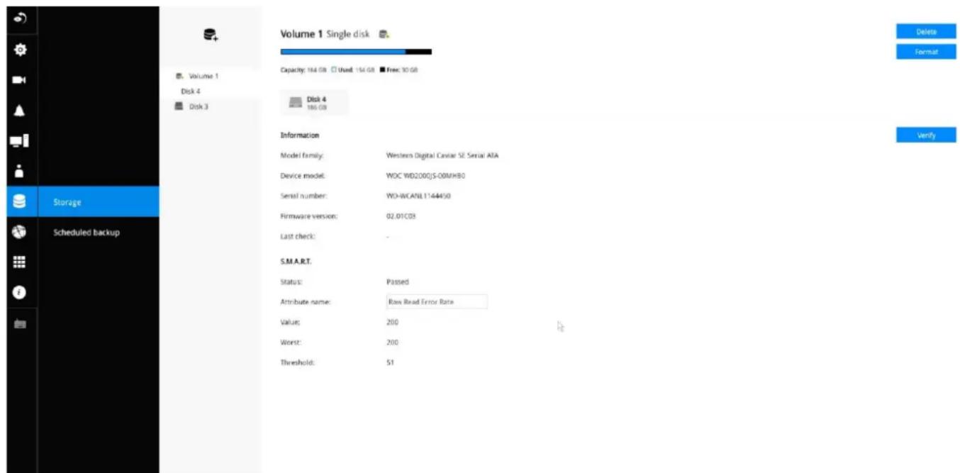
Disk Information:
Model family: The brand name of the HDD manufacturer.
Device model: The disk model name.
Serial number: Serial number assigned to the disk drive.
Firmware version: The version of firmware running on this disk drive.
Last check: The bad block check or S.M.A.R.T. test previously executed on this drive.
Status: S.M.A.R.T. status polled from the disk drive. This is not the results from a manually-executed S.M.A.R.T. test.
Attribute: The various attributes can vary from different HDD manufacturers.
Value: Value for the currently selected attribute.
Worst: Worst value acquired for that attribute.
Threshold: A predefined threshold or triggering value. The threshold below which the normalized value will be considered exceeding specifications.
Raw value: The detected parameters for that attribute.
Status: The judgement made to deem the current reading as OK or failed.
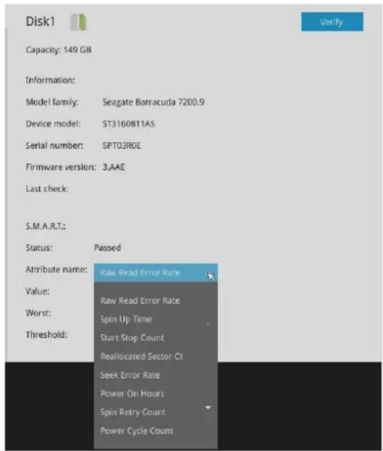
Verify:
Three types of check disk actions can be initiated through this button.
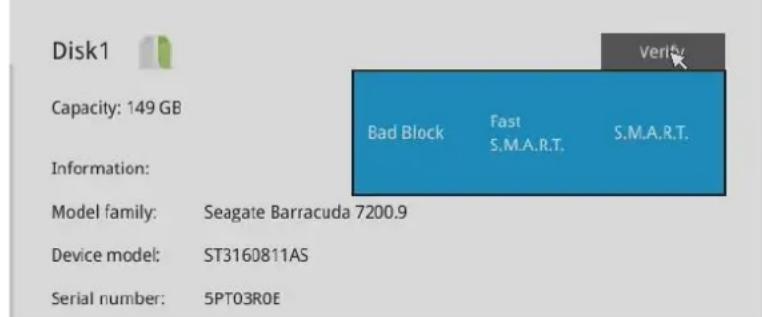
Note that disk verify function requires a volume to be temporarily disabled; namely, the video recording will be stopped before disk verify can be performed.
Bad block check: Performs read/write test to drive sectors to locate bad blocks. This action may take several hours to complete.
Fast S.M.A.R.T. test: Tests the electronic and mechanical performance and disk read performance, including those on disk buffer, read head, seek time, and integrity of drive sectors. The short test is performed on a small section of disk platters, and takes about 2 minutes to complete.
S.M.A.R.T. long test: The long test is more thoroughly and is performed to all drive sectors. The actual completion time depends on drive sizes and the attributes put to test.
The Check disk functions mentioned above, when performed during active I/Os, can consume system resources and cause dropped frames with the recording tasks.
On this configuration window, a "disk" refers to a physical disk drive, a "volume" refers to the logical configuration of disk drives which may include multiple disk drives.

IMPORTANT:
There are conditions that disk drives will not be available for storage configuration:
- The disk drives are performing the Verify process.
- The disk drives considered as "failed" drives by the S.M.A.R.T. self detection.
Restore volume:
Volume restoration allows users to backup and restore recording files, logs, and other data from a pre-established volume with hard disks on an NVR device to another NVR device. For example, HDDs on an NVR can apply the restore volume feature to reserve the original data (such as videos and logs). These HDDs can then be installed on another NVR. For example, NVR A has three HDDs using RAID0. You can select these three HDDs from NVR A, then restore these three HDDS on NVR B (even using a different slot arrangement; without any volume created).
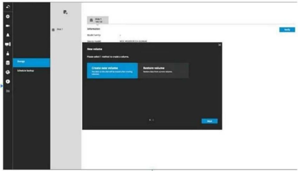
NOTES:
- This NVR supports volume restoration regardless of the hard disk's slot position on the original NVR. This function only supports data restoration between ND9442P, ND9542P, ND9326P, and ND9426P models. Data restoration is limited to the maximum number of hard drives supported by the target device.
- When restoring data to NVR B, please select the hard disk and configure the RAID settings to match the original configuration on NVR A.
- Clear the target device before starting the restoration process to avoid data conflicts.
-
The backup process supports one volume at a time.
-
The following types of data can be backed up with the volume restoration:
• System logs and customer support logs
• Alarms (alarm results only, excluding alarm settings)
• Recording data, including all video recordings and metadata
- Search results (encompassing alarm search, smart VCA event, smart search II, storyboard, attribute search, rule search, TMIS search, bookmark search, and counting data)
3-5-23. Settings - Storage - Scheduled backup
To configure a scheduled backup,
- Select the Scheduled backup: Enable checkbox.
- Server: Enter the server name or IP address of the FTP server.
- Port: Enter the port number. Default is 21.
-
Path: This is the destination folder/path if different than root.
-
Authorization: Click the Enable checkbox, and enter the User name and Password for a private FTP server (no anonymous access allowed).
-
Test FTP: Use the Test FTP button to see if your FTP server configuration is valid. If the connection is successful, an indicator will appear.

- Daily backup time: Select a time to begin the daily backup from the number pad.
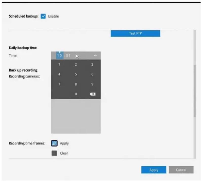
8. Backup recording
Recording cameras: By default, all cameras' recordings will be backed up. Deselect one or several cameras if you prefer to back up the recordings of only the specific cameras.
Recording time frame: Select the time span within which the recordings occurred. The recordings within the time span will be backed up. Use the Apply and Clear buttons drag your mouse cursor on the schedule pane to determine the effective hours on the schedule.
Connection: Select to enable the Upload limits by entering a number for the upper threshold of the bandwidth, e.g., 124 Kbps. Configure an upper threshold if your network bandwidth is of the concern.
Enable: Default is not selected. The scheduled backup function is not enabled by default. You must click to enable the configuration options.
Type: Currently the NVR supports the backup to an FTP server.
Enter the Static IP, domain name, and other parameters for access to an FTP server.
Site: the fully qualified domain name of a network host, or its IP address. The max. length is 253 characters. Note that hyphen “-” cannot be used at the beginning or the end of the address.
Port: The port that the remote FTP server listens on. The default ports (which are the most commonly used) are 21 for standard FTP and explicit FTPS, 990 for implicit FTPS. If necessary, change the port number. The range is 1 \~ 65535.
Path: The path is effectively a pathname of a resource and corresponds to a series of FTP commands, such as a directory tree:"ftp://jon:apple@bigcompany.com". The applicable alpha-numeric characters are [0-9][a-z][A-Z][-]/[/], with a max. length of 64 characters. If not specified, destination will be the root directory.
Authorization: Click to enter user name and password for the FTP site. Click the Test FTP button to test a connection with the FTP server. The applicable alpha-numeric characters are [0-9][a-z][A-Z][-], with a max. length of 64 characters.
Daily backup time: Default is 2:00 AM. Click to reveal the pull-down menu to specify a time when the daily backup will take place, such as that system can perform the backup in the off-office hours when network load is lower.
Backup Recording: Select the Recording cameras each by a single click. The recorded videos from the selected cameras will be backed up according to your configuration.
Upload limits: If network bandwidth is of the concern, enter an upper threshold for the bandwidth.
| Scheduled backup is starting |
| Scheduled backup has been completed successfully |
| Scheduled backup settings have been changed |
| Failed to connect to FTP server |
| Succeed to connect to FTP server |
| FTP server error (error code) |
If the FTP backup errors occur, the system will retry the connection every 5 minutes until the connection is remade or cancelled. Error messages will display on every failed attempt. For errors not related to connection problems, retry takes place every 3 seconds for 5 times for each recording file. Error messages will display on every failed attempt.
In the event of backup failures, failures will be recorded into system logs. The possible causes can be:
-
The previous backup is not finished when the succeeding backup starts, due to very slow upload speed or network problems.
-
The on-going scheduled backup is cancelled.
-
Errors occur on the storage volume while the backup is taking place. For example, when the hard disk is disconnected, formatted, or the system detects an unconfigured volume.
-
Path errors. The destination directory does not exist.
When finished with the network settings, click on the Apply button.
A proceeding backup can be manually cancelled.
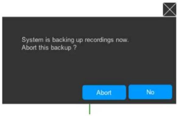
3-5-24. Settings - Network
Settings - Network - IP
DHCP: Default is selected, the server obtains an available dynamic IP address assigned by the DHCP server each time the system is connected to the LAN.
Manual setup: Select this option to manually assign a static IP address to the NVR.
Enter the Static IP, Subnet mask, Default router, and Primary DNS provided by your ISP.
Subnet mask: This is used to determine if the destination is in the same subnet. The default value is "255.255.255.0".
Default router: This is the gateway used to forward frames to destinations in a different subnet. Invalid router setting will fail the transmission to destinations in different subnet.
Primary DNS: The primary domain name server that translates hostnames into IP addresses.
Secondary DNS: Secondary domain name server that backups the Primary DNS.
When finished with the network settings, click on the Apply button.
The NVR comes with a default gateway and the cameras connected to the PoE ports are assigned with IPs within a separate network segment. The cameras connected to the PoE ports will be in a 10.1.1.x or 192.168.2.1 segment, automatically provided with subnet addresses.
The NVR's uplink port will listen to DHCP server by default.
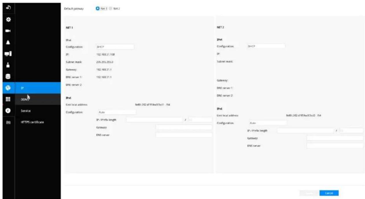
Settings - DDNS
VIVOTEK provides Dyndns.org, as a free DDNS dynamic domain name service for users who want access from the internet or a domain name service for the NVR. VIVOTEK maintains a database of product MAC addresses for the service, and you can apply one domain name for each NVR system.
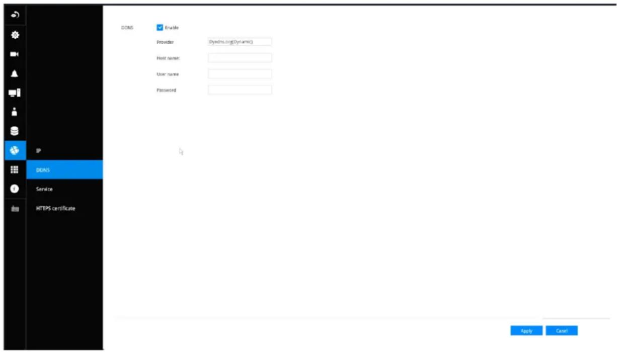
DDNS Enable: Select this checkbox to enable the DDNS setting.
Enter a Host name, Email address, and password twice, and then click Apply to proceed.
Make sure you have internet access.
Click the Register button. The terms of service agreement window is selected from a checkbox at the bottom. Click 📋 to read the license agreement terms.
The acceptable characters for email address are: [0-9][a-z][A-Z][!][#][\$][%]['*][+][-]/[=][?][^][_][']{||}[\~][.]. Two successive periods, [..], are not acceptable. The address filed can accommodate up to 256 characters.
Use only alphabetic and numeric characters for the password. The maximum number of characters is 64.
When completed, a confirm message will prompt. You will also receive a confirm Email. You can now access your NVR system using the xxxx.Dyndns.org domain name address. Note that access from the Internet should be routed to the private IP assigned to your NVR, using methodologies such as port forwarding, etc.
Settings-Service
By default, the NVR service and video streaming are accessed via HTTP port 80 and RTSP port 554. You can designate a different port number if the need arises. Usually it is not necessary to change these ports. HTTPS encrypted connection is enabled by default.
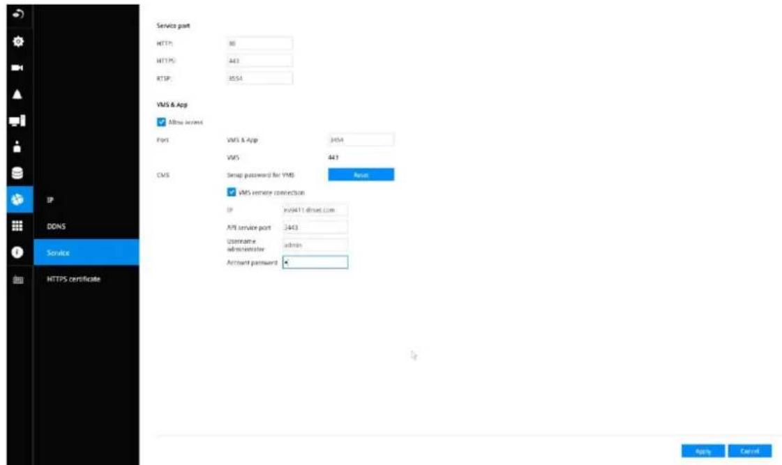
Instead of a web console, you can also access the NVR and the subordinate cameras using the iViewer and VIVOTEK's VSS software. The NVR can be managed as one of the sub-stations in a hierarchical device structure.
Set up a password for access from the VSS server before you can join the NVR to a VSS configuration. For access from the iViewer, you log in using the same username and password for the login to the NVR.
Below is the screen showing the sub-station recruitment process from a VSS server.
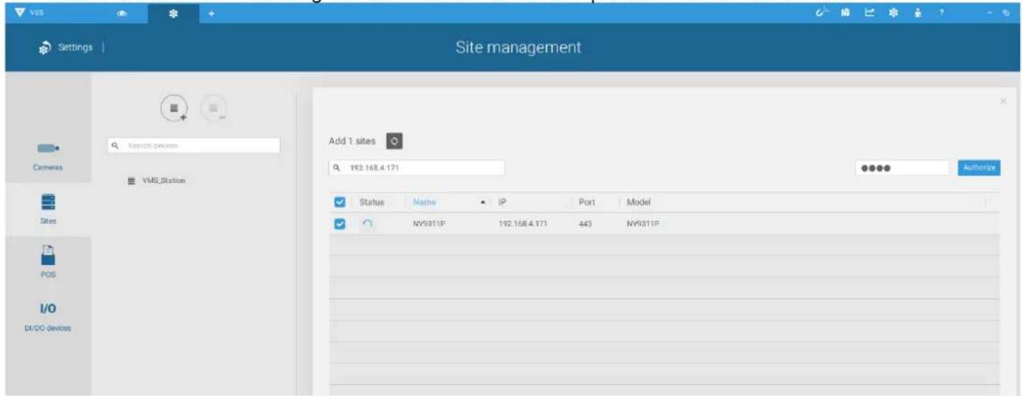
VSS auto connection
NAT-traversal with OpenVPN
A remote connection between a VSS server and an NVR with 3G/4G/LTE network can be made through an OpenVPN tunnel. The figure below shows the methodology comprising HMAC authentication and TLS encryption over an encrypted UDP connection.
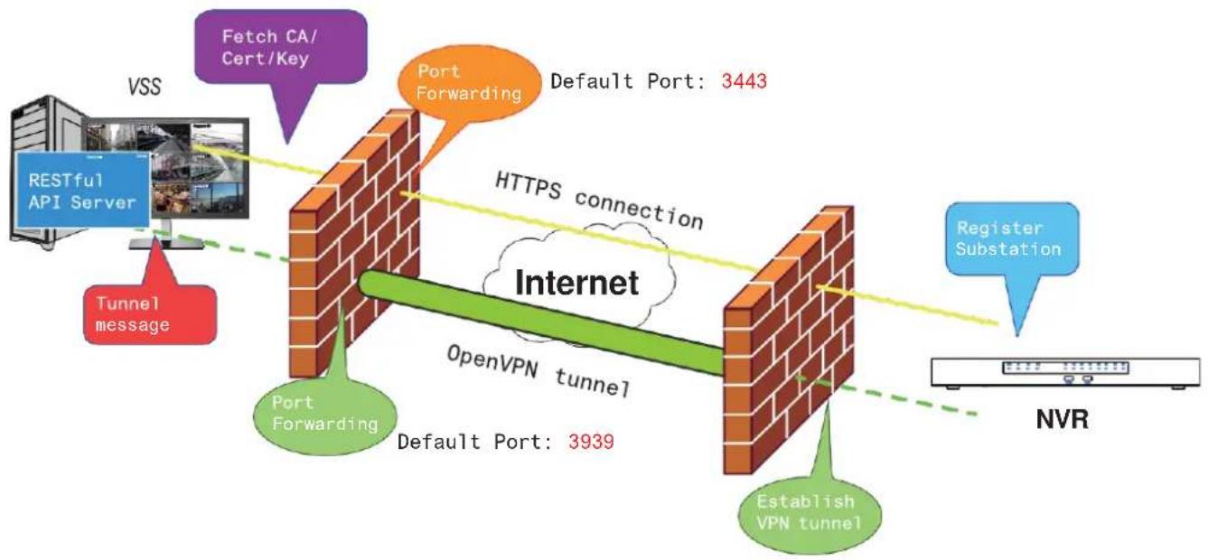
flowchart
graph TD
    A["VSS"] --> B["RESTful API Server"]
    B --> C["Tunnel message"]
    C --> D["Port Forwarding"]
    D --> E["Default Port: 3939"]
    E --> F["OpenVPN tunnel"]
    F --> G["Port Forwarding"]
    G --> H["Default Port: 3443"]
    H --> I["HTTPS connection"]
    I --> J["Register Substation"]
    J --> K["NVR"]
    style A fill:#f9f,stroke:#333
    style B fill:#bbf,stroke:#333
    style C fill:#f96,stroke:#333
    style D fill:#ff9,stroke:#333
    style E fill:#9cf,stroke:#333
    style F fill:#9cf,stroke:#333
    style G fill:#9cf,stroke:#333
    style H fill:#9cf,stroke:#333
    style I fill:#9cf,stroke:#333
    style J fill:#9cf,stroke:#333
    style K fill:#ccf,stroke:#333
Sample installation steps are shown below:
Step 1: Install VSS by selecting the Server with OpenVPN option.
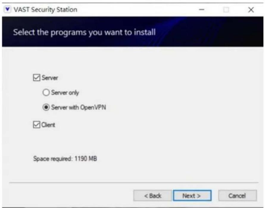
Step 2: Enable the public IP of the VSS Server.
For the NVR to establish an OpenVPN connection with the VSS Server, the user must activate the public IP of that server. (Note that the specific steps depend on the user's network environment and relevant IT policies.)
After activating the Public IP, ensure the accessibility of the HTTPS port and OpenVPN port. (Note that the VSS OpenVPN port by default is 3939, so the user must set up port forwarding with UDP.)
If the default HTTPS port (3443) is unavailable, the user must modify the corresponding port number under VSS Settings > Device > Stations. If the default port for OpenVPN (3939) is not available, the user needs to modify the configuration file of OpenVPN (located in C:\Program Files (x86)\VIVOTEK Inc\VAST\Server\OpenVPN\config\server\server.ovpn).
You can directly edit the port number in this text file (file content is shown below):
port 3939
proto udp
dev tun
ca ca.crt
cert server.crt
key server.key
dh dh.pem
server 10.6.0.0 255.255.0.0
topology subnet
client-to-client
client-config-dir "C:\\Program Files (x86)\\VIVOTEK Inc\\VAST\\Server\\OpenVPN\\ccd"
keepalive 10 120
cipher AES-256-CBC
max-clients 50000
persist-key
persist-tun
status openvpn-status.log
log-append openvpn.log
verb 3
mute 20
sndbuf 262144
rcvbuf 262144
tls-server
compress lzo
Step 3: Configure the NVR OpenVPN connection.
Once you have obtained the VSS Server public IP, configure the NVR settings under Network > Service > CMS. Then, enter the VSS server public IP/credentials/API service port (HTTPS). (Note that if the HTTPS port on the VSS end is not 3443, you must modify the corresponding port number.)
After configuring the settings for VSS and NVR, the OpenVPN connection will be established. Once the connection is established, this NVR will be automatically added to the VSS server. (Note that the NVR and VSS server should have a similar time setting when exchanging certificate information. Otherwise, the mutual handshake authentication process may fail.)
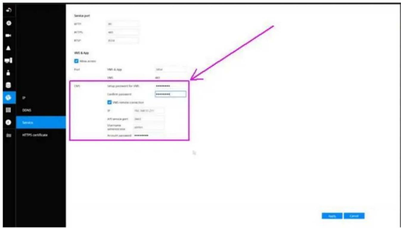
3-6. HTTPS certificate
This window allows the export, import, and to create an HTTPS certificate for secure connection to the NVR.
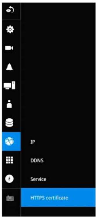
HTTPS certificate
Certificate information
| Country code | TW |
| State of province | Asia |
| Locality | Asia |
| Organization | VIVOTEK.INC |
| Organization unit | VIVOTEK.INC |
| Common name | www.vivotek.com |
| Validity | 19311 days |
| Expired on | 08 26, 2075 |
Export current certificate
Export current certificate
Create new certificate
Create self-signed certificate
( \text{Formula: } \text{and} \text{Formula: } \text{and} \text{and} \text{and} \text{and} \text{and} \text{and} \text{and} \text{and} \text{and} \text{and} \text{and} \text{and} \text{and} \text{and} \text{and} \text{and} \text{and} \text{and} \text{and} \text{and} \text{and}]
3-7. Trend Micro IoT Security Service
This NVR comes with the protection of TrendMicro security service against hackers with numerous forms of attacks. You can enable the service and let the service continuously update its virus database.
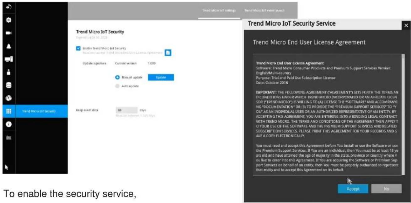
To enable the security service,
- Click the Enable checkbox.
- Read and confirm the Trend Micro End User License Agreement.
- Select whether you manually update the virus database (signatures) or let system automatically update the database. For installations where no Internet connection is available, download Trend Micro's signatures to a USB thumb drive, insert the thumb drive to update. The current Trend Micro security package will expire in the year 2020.
Please contact your sales representative if your security package expires.
- Cybersecurity management for cybersecurity alert, event log, and event logging. The NVR comes with TrendMicro security package, and can receive cyber attack information from cameras. Also, these events can be collected by the VAST software.
3-8. Information
This window shows the revision number of the firmware running on this machine.
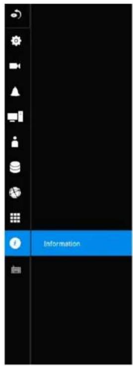



3-9. Limitation when working with VSS
• VSS cannot change the video channel settings managed by NVR.
• VSS cannot change the URL content added by RTSP.
- For the SD series with smart tracking, VSS does not support the smart tracking settings on the PTZ page.
Section Two: Management over a Web Console
Below are the requirements for using a web console:
- i5 CPU or above with a minimum of 8GB RAM.
- It is recommended to configure a sub stream in H.264, with a lower resolution of 640 x 360.
- Use Google Chrome for the plug-in free access.
There are two different interfaces on the system:
-
One is connecting mouse and keyboard, and an HDMI cable to a TV screen or monitor. The local management thus made is described in the User Manual of each NVR model.
-
The other is accessed through the Ethernet connection. Management via a web console is described in this manual.
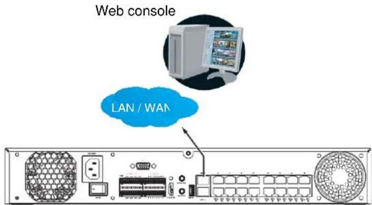
Note that when accessed over the network, the total streaming throughput is 24Mbps.
Access via an IPv6 address is supported by firmware revision 3.1. Note that for some browsers you should use the [ and ] brackets to surround the IPv6 address such as: http://[2001:db8:1234::abcd].
Chapter 4: Login and Getting Started
4-1. Login
This is the login page on the browser. The minimum resolution is 1280x960.
Please use Google Chrome to access the NVR. By default, the web console opens with the new user interface.
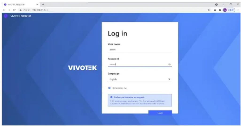
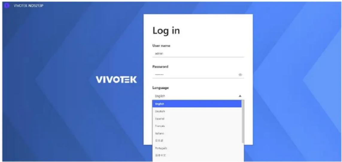
It is highly recommended that you should change the default password. Please refer to Settings > Security > User account page to see how to prevent unauthorized access. The system will prompt you if you entered an incorrect username or password.
Remember me: Your username will be preserved in browser cookies for two days if you select the Remember me checkbox. The username will be automatically erased if you do not log in to the system for two days.
You may login to a different software utility by unfolding the side panel on the Login button.
You can also select a different language using the Multilingual selector menu on the lower left corner of the Login screen. The functional items, menus, and dialogues will then be displayed using the selected language.
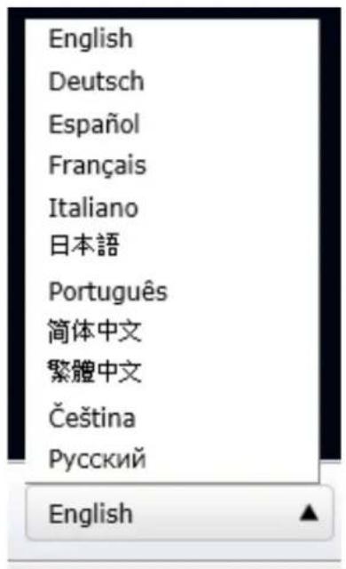
Login errors: below are the login errors that might occur.
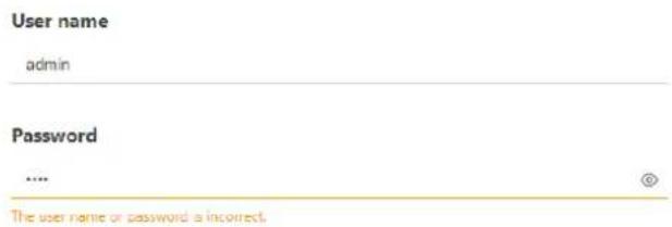
A Login failure can result from the incorrect user name and passwords.
Login options:
You may also mouse over the Login button to display the login options. You can then enter the Live view, Playback, or Alarm search window.
The NVR system features a simple UI structure which consists of a Live view window, a Playback utility, and a system Settings window. Once logged in, you can move from one window to another by selecting the hot link buttons on the upper right of the screen.
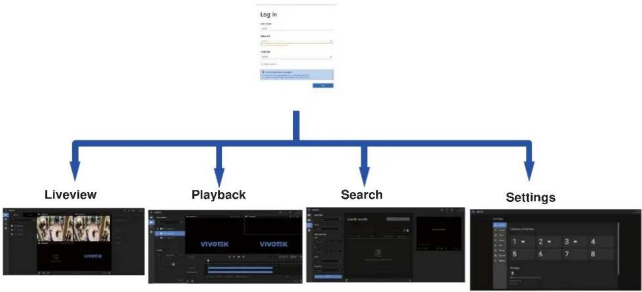
flowchart
graph TD
    A["Log In"] --> B["Liveview"]
    A --> C["Playback"]
    A --> D["Search"]
    A --> E["Settings"]

NOTE:
The NVR supports plug-in-free web sessions using Chrome browsers.
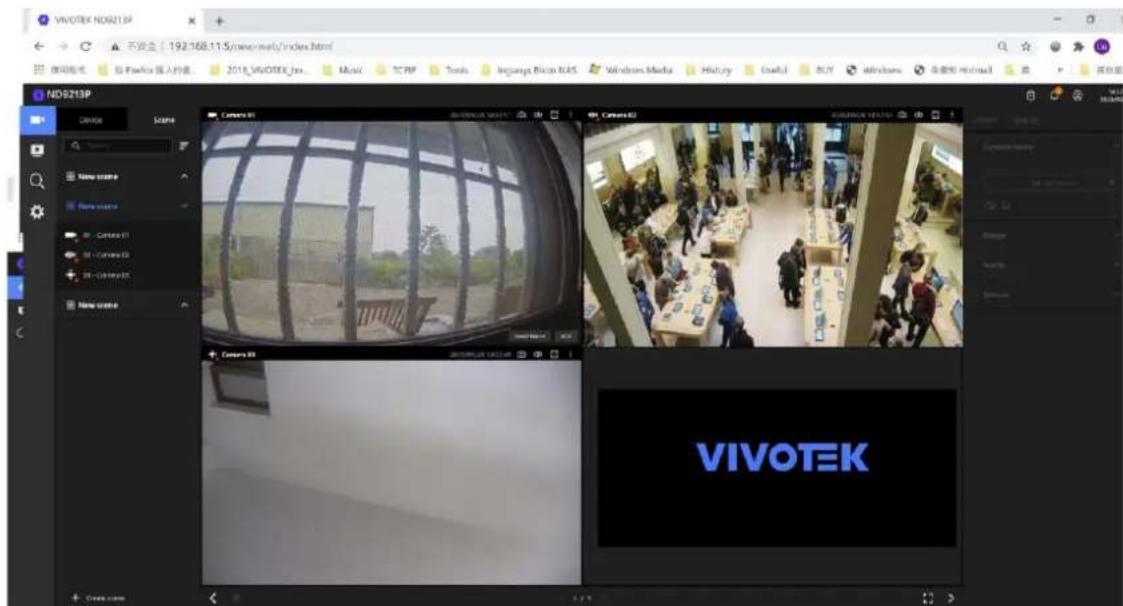

IMPORTANT:
-
Before operating the NVR, make sure you have properly installed hard drives and configured the storage volumes. Otherwise, you will not be able to operate some of the system's functionality.
-
When you log in to the Live view or Playback interface to stream a live or recorded video, install the ActiveX plug-ins. If it does not prompt when you log in, install plug-ins when you try to playback a recorded video. You may then need to re-start the IE browser console.
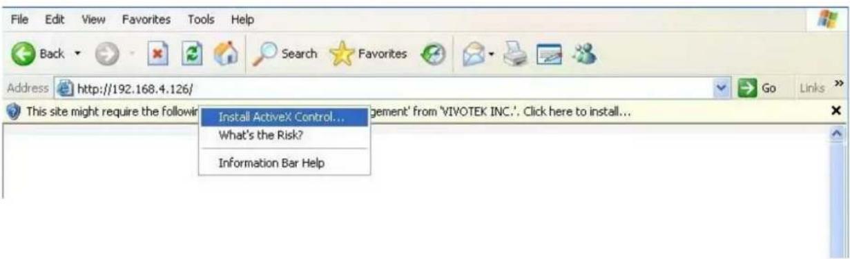
4-2. Graphical Layout and Screen Elements - Live view
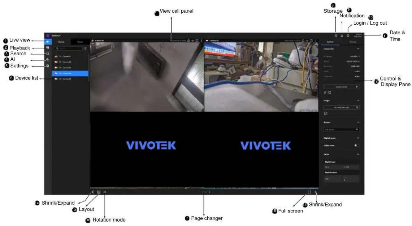
Once you log in, the system defaults to the Live view page, which provides access to other configuration utilities, live view screen, and other functional panels. The screen elements are described as follows:
| Item | Name | Description |
| 1 | Live view | Provides a glimpse of all cameras inserted into your configuration. |
| 2 | Playback | Provides access to camera recordings. |
| 3 | Search | Provides access to the Alarm search panel. |
| 4 | AI Search | Provides access to the AI metadata search panel. |
| 5 | Device list | All devices (cameras / video servers) that have been recruited into the configuration will be listed. |
| 6 | Settings | Provides access to system settings. |
| 7 | View cell panel | The video feeds from cameras will be placed into view cells. |
| 8 | Storage | Provides a glimpse of current storage usage. |
| 9 | Notification | System notifications including system events and alarm notifications. |
| 10 | Login/Log out | You can log out and log in again using another user role. |
| 11 | Date & Time | Displays date and time. You can click to enter the date and time setting page. |
| 12 | Control & Display pane | When a view cell is selected, the camera-specific control (such as PTZ) and display options will be available here. |
| 13 | Shrink / Expand | You can display or hide the side panes. |
| 14 | Layout | Provides functions to extend, rotate, and redo the layout. |
| 15 | Rotation mode | Click to enter the Rotation mode. |
| 16 | Page changer | Click to move to the other layout page when your live views are distributed over many pages. |
| 17 | Full screen | Enters the full screen with only the live views. |
Each panel will be described in further discussions.
4-2-1. Device List Panel
The Device list displays the recruited cameras by the sequential numbering order you configured in the System Settings utility.
If a user logged in using a credential of a limited access, he may only see cameras that he can access instead of all of the cameras.
Camera Icon:
A mouse click on the camera name on the Device list brings forth the summary of IP address, model name, recording setup, DI/DO information, and other control elements on the right pane.
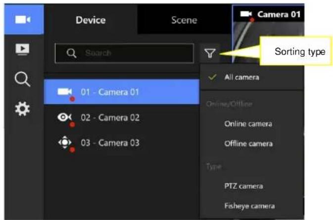
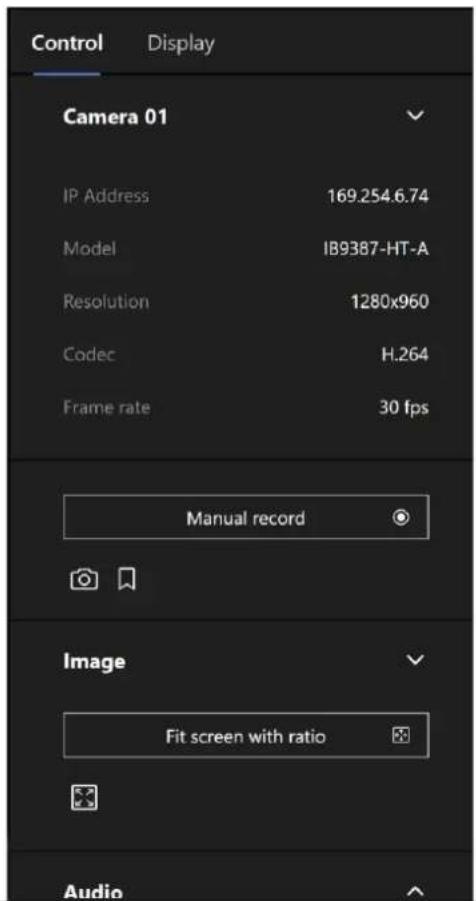
Once devices are added to the NVR, they will be listed. The device type will be automatically detected. Different types of devices will be given different types of device icons.
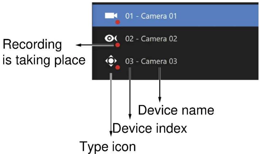
Different types of devices will be given different types of device icons. For example,
| Box or Bullet cameras. | |
| Fisheye cameras. | |
| PTZ cameras. |
View Cell elements:
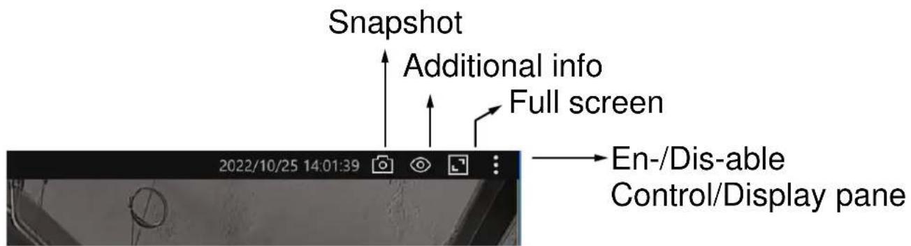
| 14:50:032023/11/21 | |
| adminADMINISTRATOR | Display |
| Language | |
| Restart | |
| Log out | |
4-2-2. Layout
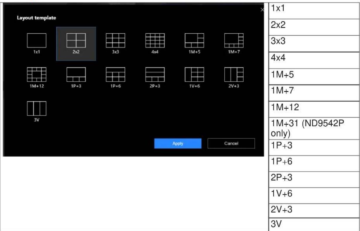
Only an administrator can change and preserve a custom layout, and every user can designate a specific layout to be displayed when he/she logs in. The default layout for each user is stored in a browser's cookies.
The available layouts are categorized into 4 types: Equal, Panorama, Focus, and Vertical. Equal: 1x1, 2x2.
Panorama: 1P(Panoramic)+6, 2P+3. (applies to fisheye cameras)
Focus: 1M+5, 1M+7.
Vertical: 1V+6, 2V+3, 3V. (applies to corridor view)
Note that a user who did not log in as an administrator can change a layout, but his configuration changes (with cameras placed on view cells) will not be saved.
4-2-3. Scene
A scene allows users to gather the live views from multiple cameras together into a comprehensive glimpse of view. For example, several cameras may have been installed to cover a specific area.
To create a new scene, click on the Create scene button.
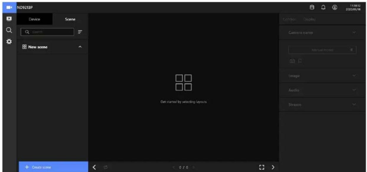
You can change layout, enter a name for the new scene, and click and drag cameras into the layout. When done, click the Create button. ++
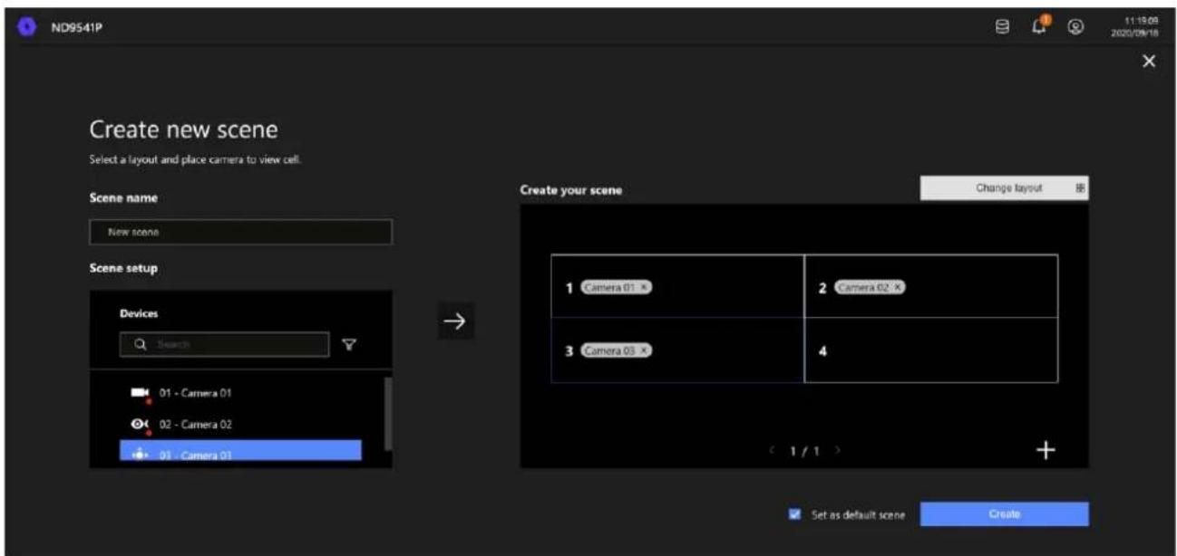
In the Scene view, you can place 1 camera into multiple view cells. This applies when using cameras with a wide coverage area, such as fisheye or multi-lens cameras.
4-2-5. View Cell panel
A single view cell is shown below. Each view cell contains a video stream display area, information, and functional buttons. A view cell is displayed in Normal, Focused, or Maximized mode.
- A single click selects a view cell from the View Cell panel, enables its function buttons, and turn it into the Focused mode.
- A double-click maximizes the size of the view cell to the full of the panel.
- The 2nd double-click shrinks the maximized view back into the focused mode.
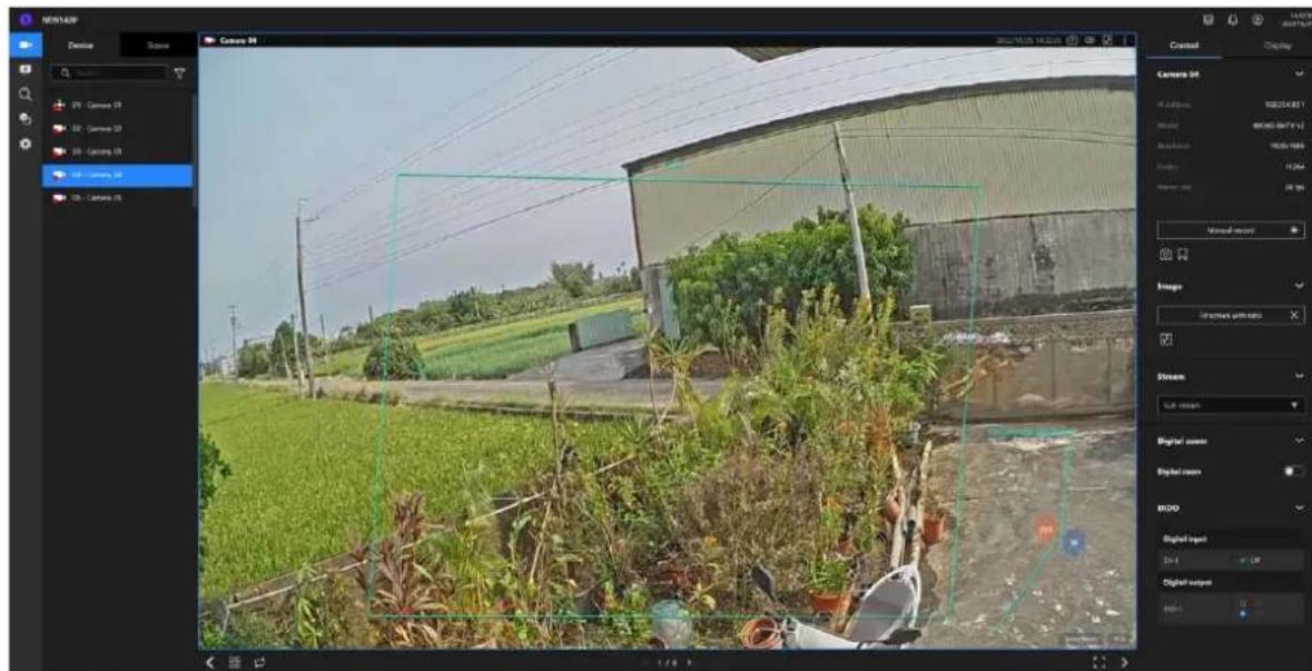
Although the system automatically selects the video stream to display on the view cell, you can still manually select a different video stream from the Stream tab below.
To deselect a view cell and return to the normal view, click on the Restore button at the lower screen.
Adding Cameras to View Cells
- Click and drag a camera from the Device list to an unoccupied view cell.
- Double-click a camera on the camera list. The camera will be added to the first available view cell.
To deselect a view cell and return to the normal view, double-click on the view cell. You can also click on another view cell to continue adding other cameras.
The system automatically adds cameras into view cells by their index numbers. If you prefer a different order and placement, use the Scene mode to create different placements.
Sometimes network problems can cause a view cell to be attempting to connect to a network camera. If the connection attempt takes a long time, it may result from network problems or incorrect configuration with video streaming. For example, you may have configured the camera to be streaming a 5MP stream. The NVR uses video main stream for recording, and the main or sub stream from cameras for live viewing. You should then open an individual web console to the network camera to change its video streaming configuration.
If the current layout already contain the max. number of cameras, e.g., 9 for the 4-CH model, the following message will prompt.

Not able to add camera
Current layout already has 16 cameras.
If you are using the 16-CH model, there can be more than 16 view cells across multiple layout pages, e.g., on the second page of the 1M+12 layout. Placing a camera in the 17th to 18th view cells will bring out the following message.

Not able to add camera
Could not place camera here. Try other view cells.
Control Pane
Click to select any of the view cells to activate its Control and Display panes.
You can exert the following:
- View basic information such as the IP address, Model name, etc.
- Start a manual recording.
- Take a snapshot.
- Place a bookmark if you find something of your interest. The bookmark is preserved as a one-minute footage along with a short description of a particular incident. The precondition of using this function is that the video stream, while you are watching it on the view cell, must be recorded to the NVR at the same time.
- Tune the audio volume.
- Select a different stream.
- Enable the Digital Zoom (using the mouse wheel).
- Manually toggle the Digital Output.
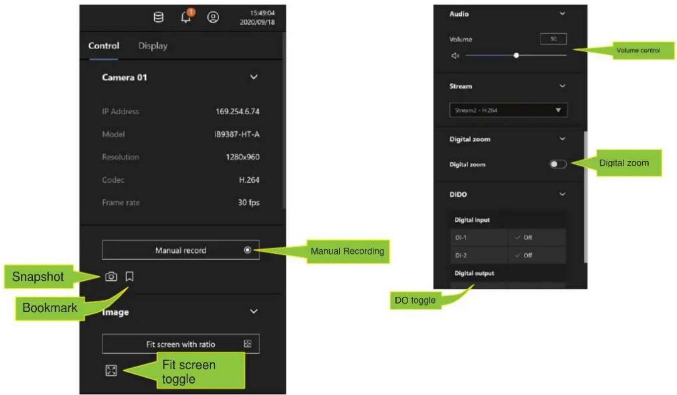
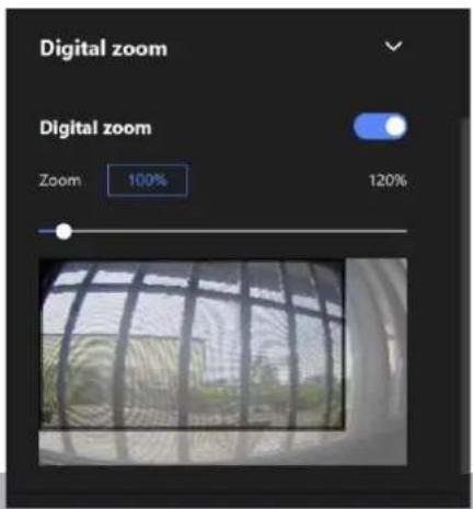
* For a fisheye camera, you can select a dewarp mode as a Regional view or a Panoramic view.
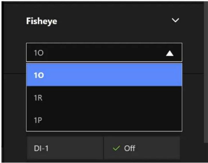
10 (Original view)
10 View (Original View)
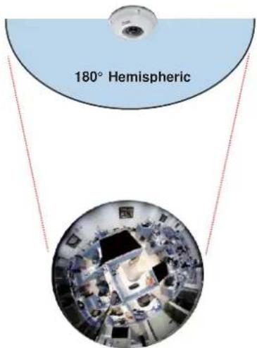
1P (Panoramic view)
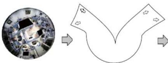
flowchart
graph TD
    A["Top: Office Space"] --> B["Y-shaped Flow"]
    B --> C["Arrow 1: Left"]
    B --> D["Arrow 2: Right"]
    B --> E["Arrow 3: Bottom"]
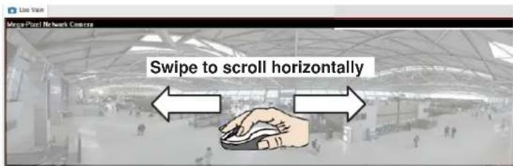
1R (Regional view)
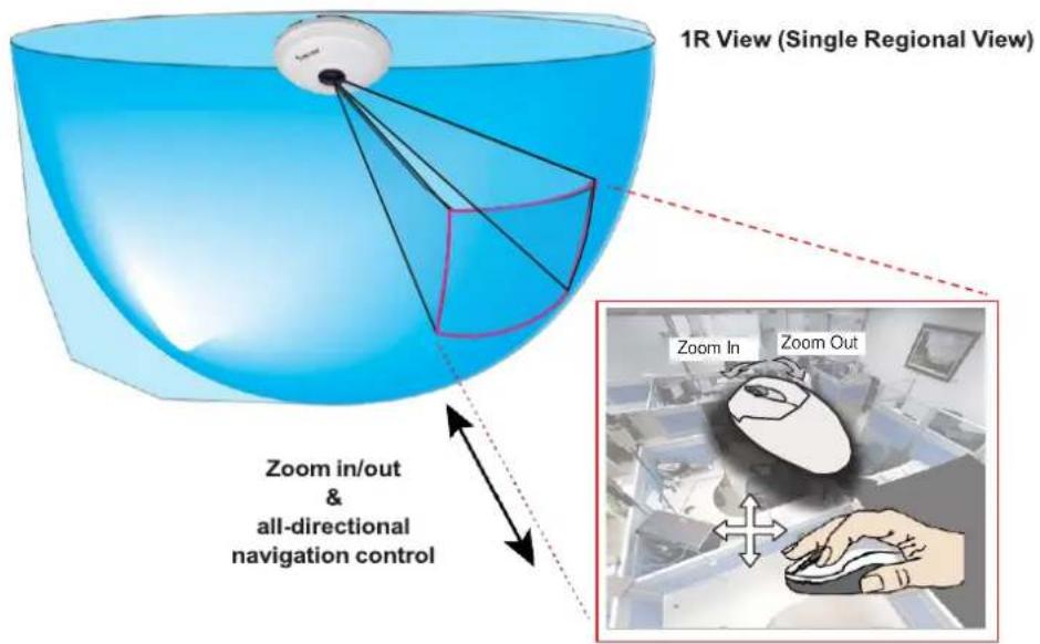
The 1R mode (or rectilinear) provides access to one image section within the hemisphere. You can zoom in or out (using the mouse wheel or PTZ panel) or travel through to other areas within the hemisphere using simple mouse clicks and drags. A single click on a particular object can bring the object to the center of your view window. Click and hold down the left mouse button, and you can swipe the view both horizontally and vertically.
Note that if your fisheye mounting type is set to the Wall Mount type, your screen control in the view cell will be limited to 90° pan and tilt. Make sure your mounting type and camera settings have been properly configured.
Because fisheye lens can cover a wide surveillance area, you can insert a fisheye camera into multiple view cells, and let different regional views display in these view cells. In this way, you can have a glimpse of multiple areas of interest, and the configuration of these different view windows will be preserved when you save your layout settings.
* For a PTZ camera, scroll down to display the PTZ control panel where you can zoom, focus, pan, patrol, or move the camera lens.
On a live view of a PTZ camera, you can hold down the mouse button and move the cursor towards the direction you want to move. The mouse control is automatically enabled for PTZ cameras. As depicted below, the farther you move along the screen, the faster the lens module moves.
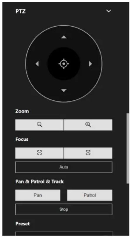
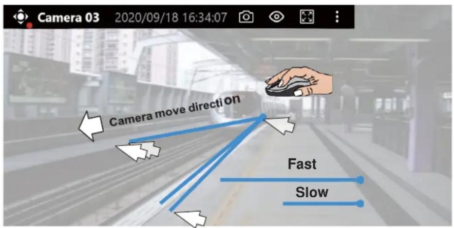

NOTE:
Bookmarks will be erased if the user/system erases the video clips they were appended to. For example, system will recycle storage space by deleting old videos along with their bookmarks.
Auto pan/patrol controller: These buttons provide pan and patrol functions provided that preset locations have been configured on the camera. For a speed dome camera, the pan command tells the camera to continuously pan 360 degrees until it is stopped by a user command.
The Stop button ends a pan or patrol tour.
Display Pane
On the Display pane, you can configure the following:
- Enable or disable the display of the Camera type, the small icon on the upper left of view cell.
- Camera name and IP address. Select one or both.
- Displays camera time.
- Displays Camera status: Trend Micro IoT Security and Video content analysis. If your camera supports these features, you can choose to display them on the live view.
You can enable the display features on all view cells using the Apply to all view cells button.
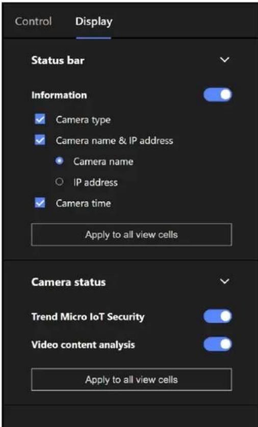
4-3. Graphical Layout and Screen Elements - Playback
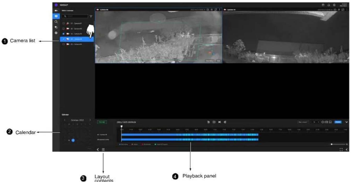
The screen elements of the Playback window are described as follows:
| Item | Name | Description |
| 1 | Camera List | Provides a glimpse of all cameras that have recorded data. Basic information is also provided along with a screenshot. |
| 2 | Calendar | Shows when the recording took place, and thus enables users to quickly locate a specific part of recording in history. |
| 3 | Layout contents | Provides functions to extend, rotate, redo the layout, and the synchronous playback. |
| 4 | Playback panel | Displays the playback functions. Snapshot, bookmark, and export functions are also available on individual view cells. |
To begin playback and search for past recordings,
- Single click to select a camera. You can select multiple cameras.
- The Calendar panel will display the days video recording actually took place. And those days will be highlighted by a lighter text. Click to select the days with recordings.
Playback Panel
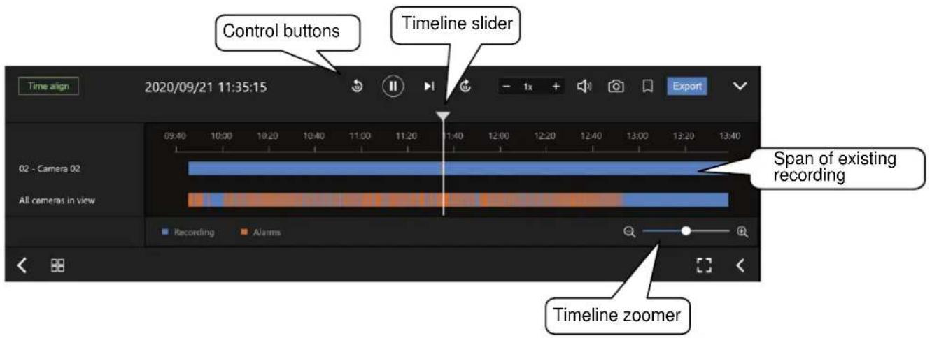
The time slide bar enables quick skimming through the recording. Its functional buttons are described as follows:
| Buttons | Description |
| Pause | |
| Play. This button is available after you manually pause a playback. | |
| Next frame. After you paused a playback, use this button to browse video frame by frame. | |
| Plays back 10 seconds before. | |
| Plays back 10 seconds later. | |
| - 1x + | Speeds up or speeds down. Speeds down by 1/2. The slowest speed is 1/8. Speeds up. Increases the playback speed, to 2x or 4x. |
| Playback volume tuner. | |
| Takes a snapshot of the current playback screen. | |
| Places a bookmark on the current recording. |
| Timeline zoomer. Use the zoomer to zoom in for more precise skimming. | ||
| Time align | Lets the cameras in the scene play the recording of the same time. | |
| Export | When you find something of your interest, use the Export function to export a video clip.Select the length of the video clip using the Start and Stop time menus below. Depending on the length of clips, an export can take a while to finish.The default export length is 30 minutes. | |
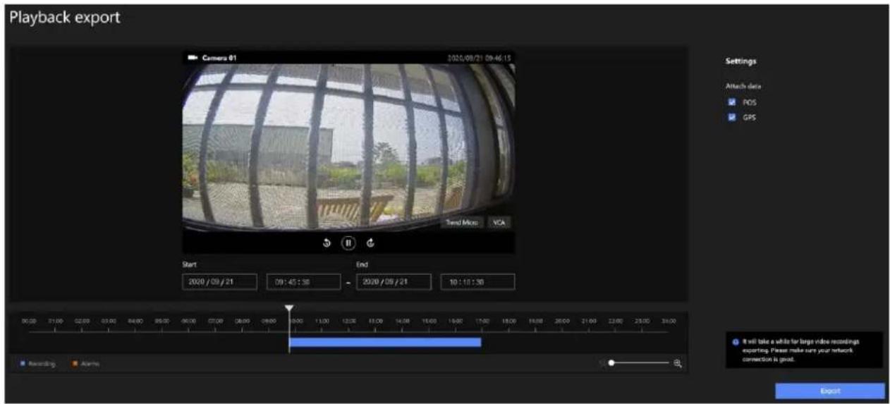
Note that for specific cameras, such as fisheye cameras, you can click its view cell to display its control options such as the dewarp type.
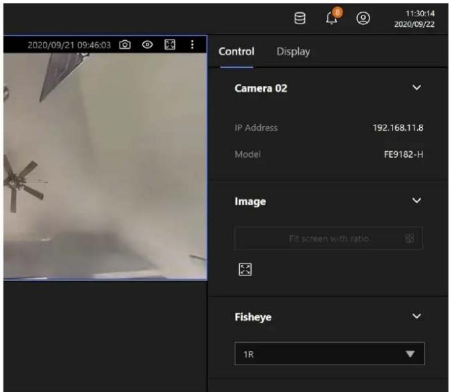
4-4. Graphical Layout and Screen Elements - Search
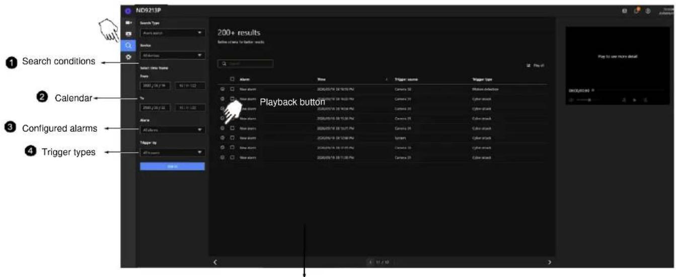
5 Search results
The screen elements of the Playback window are described as follows:
| Item | Name | Description |
| 1 | Search conditions | The whole panel provides access to search conditions. You can select Devices, time span, pre-configured alarms, or trigger types. |
| 2 | Calendar | Shows when the possible time of occurrence of alarms. |
| 3 | Configured alarms | Select the alarms you previously configured on the system. |
| 4 | Trigger types | There are many trigger types including system event triggers, cyber attacks, DI/DO, or the numerous VCA detection triggers. |
| 5 | Search results | The results are displayed by Alarm name, Time of occurrence, Trigger source, and the Trigger type. |
To begin playback and search for past recordings,
- Single click to select a camera. You can select multiple cameras.
- The Calendar panel will display the days video recording actually took place. And those days will be highlighted by a lighter text. Click to select the days with recordings.
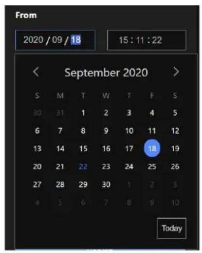
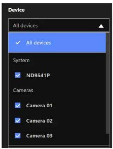
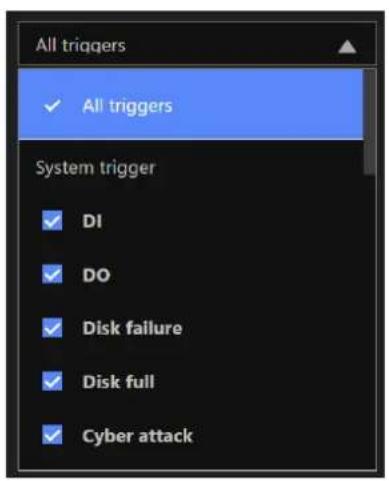
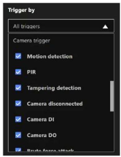
Chapter 5: System Settings
The System Settings pages are made identical to those on the local console. Since the Setting pages are identical, the following pages will be omitted. Please refer to page 97 for the description of System Settings via a local console.
Some minor differences between the web console and local console exist. One is the Restore Factory default function. It is only available on the web console.
The restore function is not available on the local console, for users can use the reset button to perform the system default restoration.
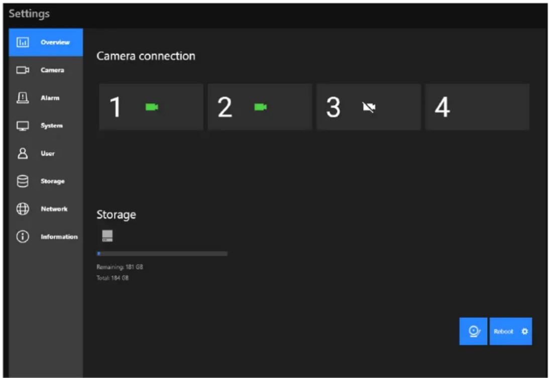
Another difference is the ability to enter a camera or system name using languages other than English. The NVR's system name also supports the use of other languages. This is only achievable through a web console.
The following characters are not supported:
[>][<][)][(]["][%][;][#][&][+][-][]
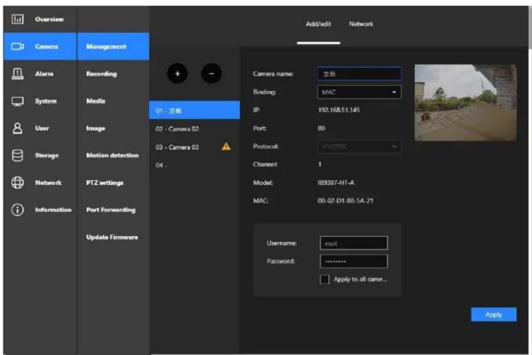
Safety and Compatibility

Federal Communications Commission (FCC) Statement
This Equipment has been tested and found to comply with the limits for a Class A digital device, pursuant to Part 15 of the FCC rules. These limits are designed to provide reasonable protection against harmful interference when the equipment is operated in a commercial environment. This equipment generates, uses and can radiate radio frequency energy and, if not installed and used in accordance with the instructions, may cause harmful interference to radio communications. Operation of this equipment in a residential area is likely to cause harmful interference in which case the user will be required to correct the interference at his own expense.
Warning:
[A shielded-type power cord is required in order to meet FCC emission limits and also to prevent interference to the nearby radio and television reception. It is essential that only the supplied power cord be used.]
[Use only shielded cables to connect I/O devices to this equipment.]
You are cautioned that changes or modifications not expressly approved by the party responsible for compliance could void your authority to operate the equipment.
[ ]: depend on EUT condition.
Information on Disposal for Users of Waste Electrical & Electronic Equipment (private households)

natural_image
Simple line drawing of a trash bin with two crossed lines indicating no waste or prohibition (no text or symbols)This symbol on the products and/or accompanying documents means that used electrical and electronic products should not be mixed with general household waste.
For proper treatment, recovery and recycling, please take these products to designated collection points, where they will be accepted on a free of charge basis. Alternatively, in some countries you may be able to return your products to your local retailer upon the purchase of an equivalent new product.
Disposing of this product correctly will help to save valuable resources and prevent any potential negative effects on human health and the environment which could otherwise arise from inappropriate waste handling. Please contact your local authority for further details of your nearest designated collection point.
Penalties may be applicable for incorrect disposal of this waste, in accordance with national legislation.
For business users in the European Union
If you wish to discard electrical and electronic equipment, please contact your dealer or supplier for further information.
Information on Disposal in other Countries outside the European Union
This symbol is only valid in the European Union. If you wish to discard this product, please contact your local authorities or dealer and ask for the correct method of disposal.
Technology License Notice

Notices from HEVC Advance:
THIS PRODUCT IS SOLD WITH A LIMITED LICENSE AND IS AUTHORIZED TO BE USED ONLY IN CONNECTION WITH HEVC CONTENT THAT MEETS EACH OF THE THREE FOLLOWING QUALIFICATIONS: (1) HEVC CONTENT ONLY FOR PERSONAL USE; (2) HEVC CONTENT THAT IS NOT OFFERED FOR SALE; AND (3) HEVC CONTENT THAT IS CREATED BY THE OWNER OF THE PRODUCT. THIS PRODUCT MAY NOT BE USED IN CONNECTION WITH HEVC ENCODED CONTENT CREATED BY A THIRD PARTY, WHICH THE USER HAS ORDERED OR PURCHASED FROM A THIRD PARTY, UNLESS THE USER IS SEPARATELY GRANTED RIGHTS TO USE THE PRODUCT WITH SUCH CONTENT BY A LICENSED SELLER OF THE CONTENT. YOUR USE OF THIS PRODUCT IN CONNECTION WITH HEVC ENCODED CONTENT IS DEEMED ACCEPTANCE OF THE LIMITED AUTHORITY TO USE AS NOTED ABOVE.
H.264
THIS PRODUCT IS LICENSED UNDER THE AVC PATENT PORTFOLIO LICENSE FOR THE PERSONAL AND NON-COMMERCIAL USE OF A CONSUMER TO (i) ENCODE VIDEO IN COMPLIANCE WITH THE AVC STANDARD ("AVC VIDEO") AND/OR (ii) DECODE AVC VIDEO THAT WAS ENCODED BY A CONSUMER ENGAGED IN A PERSONAL AND NON-COMMERCIAL ACTIVITY AND/OR WAS OBTAINED FROM A VIDEO PROVIDER LICENSED TO PROVIDE AVC VIDEO. NO LICENSE IS GRANTED OR SHALL BE IMPLIED FOR ANY OTHER USE. ADDITIONAL INFORMATION MAY BE OBTAINED FROM MPEG LA, L.L.C. SEE HTTP://WWW.MPEGLA.COM
- VCCI規制について
ACA (Australian Communications Authority)
CAUTION RISK OF EXPLOSION IF BATTERY IS REPLACED BY AN INCORRECT TYPE.
DISPOSE OF USED BATTERIES ACCORDING TO THE INSTRUCTIONS

- Table of Contents
- Chapter 1: Hardware Installation and Initial Configuration.... 8
- Section One: Management over a Local Console.... 46
- Chapter 2: Introduction to the Local Console Interface.... 46
- Chapter 3: Configuration Using the Local Console....61
- Section Two: Management over a Web Console.... 178
- Chapter 4: Login and Getting Started.... 179
- IMPORTANT:
- NOTE:
- Revision History
- Package Contents
- Symbols and Statements in this Document
- Chapter 1: Hardware Installation and Initial Configuration
- Introducing the Network Video Recorder
- Special Features
- Safety
- Rear View
- Hardware Installation
- Rack-mounting (Optional, and the rack-mount brackets are separately purchased)
- Interface Connections
- 2-6. Limitations:
- Terminal Block Connections
- WARNING:
- Limitations on text entry length:
- Initial Configuration - via a Local Console
- Power Up and Power Down
- Configuring Crowd Control Solution
- NO COUNTING DATA
- Advanced:
- Configuring Alarm Notification:
- Customizable Screen Configuration:
- Section One: Management over a Local Console
- Chapter 2: Introduction to the Local Console Interface
- 2-1. How to Begin
- How to access the Configuration Portal?
- How to access the Camera Portal?
- Tips:
- How to retrieve and access recorded videos?
- How to receive system alarm?
- Why live view is unavailable?
- How do I move to another layout page?
- Why the onscreen tool bars disappear after some time?
- 2-2. Operation on Camera View Cell
- 2-2-1. PTZ Panel
- 2-2-2. Digital zoom Panel
- 2-2-3. Play Recording Clips Panel
- 2-2-4. DI/DO
- 2-2-5. Others
- IMPPORTANT:
- 2-2-6. Right-click Commands
- Chapter 3: Configuration Using the Local Console
- The Main Control Portal
- 3-1. Layout
- 3-2. DI/DO
- 3-3. Search recording clips
- 3-3-1. Basic Search
- 3-3-2. Alarm Search
- 3-3-3. Smart Search II
- 3-3-4. Deep Search
- Scene Search:
- 3-3-5. Smart VCA event search
- Line Crossing Detection
- Intrusion Detection
- Loitering Detection
- Missing Object Detection
- Unattended Object Detection
- Face Detection
- Crowd Detection
- Running Detection
- Parking Violation
- Restricted Zone
- Smart Tracking
- 3-3-6. Storyboard
- hours/mins
- 3-4. Export recordings
- 3-5. Settings
- 3-5-1. Settings - Overview
- 3-5-2. Settings-Camera-Management
- Network
- Camera position
- 3-5-3. Settings-Camera-Recording
- Recording options
- NOTES:
- Recording Schedule
- 3-5-4. Settings—Camera—Media
- For Playback:
- Video
- ■ Dynamic Intra frame period
- Audio
- 3-5-5. Settings - Camera - Image
- Display
- Day/Night settings
- Switch to B/W in night mode
- IR cut filter
- Image settings
- Scheduled:
- Exposure:
- Focus:
- Exposure, Focus, Privacy mask, Lens
- 3-5-6. Settings-Smart VCA Detection
- Motion Detection
- 3-5-7. Settings—Camera—Motion Detection
- 3-5-7. Settings - Camera - PTZ settings
- To configure a patrol:
- 3-5-8. Settings - Camera - Port forwarding
- 3-5-9. Settings - Camera - Update firmware
- 3-5-10. Settings—Alarm—Alarm
- 3-5-11. Settings - Alarm - Email
- 3-5-12. Settings—System—Information
- 3-5-13. Settings–System–Maintenance
- 3-5-14. Settings - System - Display
- 3-5-15. Settings - System - PoE management
- 3-5-16. Settings - System - UPS
- 3-5-17. Settings - System - Log
- 3-5-18. Settings - System - Cloud service
- 3-5-19. Settings – System - Customer support
- Debug logs
- Remote access
- 3-5-20. Settings-User
- admin
- 3-5-21. Settings-User-Login / Logout
- Login
- Logout
- 3-5-22. Settings-Storage
- Disk Information:
- Verify:
- Restore volume:
- 3-5-23. Settings - Storage - Scheduled backup
- Backup recording
- 3-5-24. Settings - Network
- Settings - Network - IP
- Settings - DDNS
- Settings-Service
- VSS auto connection
- NAT-traversal with OpenVPN
- 3-6. HTTPS certificate
- HTTPS certificate
- 3-7. Trend Micro IoT Security Service
- 3-8. Information
- 3-9. Limitation when working with VSS
- Section Two: Management over a Web Console
- Chapter 4: Login and Getting Started
- 4-1. Login
- Login options:
- 4-2. Graphical Layout and Screen Elements - Live view
- 4-2-1. Device List Panel
- Camera Icon:
- 4-2-2. Layout
- 4-2-3. Scene
- 4-2-5. View Cell panel
- Adding Cameras to View Cells
- Control Pane
- 1R (Regional view)
- Display Pane
- 4-3. Graphical Layout and Screen Elements - Playback
- 4-4. Graphical Layout and Screen Elements - Search
- Chapter 5: System Settings
- Safety and Compatibility
- Information on Disposal for Users of Waste Electrical & Electronic Equipment (private households)
- For business users in the European Union
- Information on Disposal in other Countries outside the European Union
- Technology License Notice
- Notices from HEVC Advance:
- H.264
- - VCCI規制について
Brand : Vivotek
Model : ND9426P
Category : Video recorder