
NV9311P - Video recorder Vivotek - Free user manual and instructions
Find the device manual for free NV9311P Vivotek in PDF.


| Product Type | Network Video Recorder (NVR) |
| Model | NV9311P |
| Brand | Vivotek |
| Video Channels | 9 Channels (8+1) |
| PoE Ports | 11 built-in PoE ports (IEEE 802.3af/at) |
| Storage Capacity | Supports up to 2 HDDs (SATA), maximum 10 TB each |
| Video Compression | H.265, H.264, MJPEG |
| Recording Resolution | Up to 8MP (4K) per channel |
| Audio Support | 2-way audio via compatible cameras |
| Remote Access | Via web browser, mobile app (iViewer), or CMS |
| Network Interface | 2 Gigabit Ethernet ports |
| Power Supply | 100-240V AC, 50-60Hz, internal power supply |
| Power Consumption | Max 150W (including PoE output) |
| Dimensions (W x D x H) | 300 x 230 x 45 mm |
| Weight | 2.5 kg (without HDDs) |
| Operating Temperature | 0°C to 50°C (32°F to 122°F) |
| Humidity | 10% to 90% (non-condensing) |
| Mounting | Desktop or rack-mountable (bracket included) |
| Maintenance | Clean exterior with dry cloth; avoid liquid; ensure ventilation |
| Safety | Use grounded power outlet; do not overload circuits |
| Spare Parts & Repairability | Contact Vivotek or authorized service center for replacements |
Frequently Asked Questions - NV9311P Vivotek
User questions about NV9311P Vivotek
0 question about this device. Answer the ones you know or ask your own.
Ask a new question about this device
Download the instructions for your Video recorder in PDF format for free! Find your manual NV9311P - Vivotek and take your electronic device back in hand. On this page are published all the documents necessary for the use of your device. NV9311P by Vivotek.
USER MANUAL NV9311P Vivotek
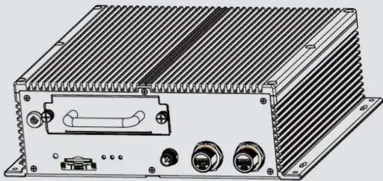
NV9311P, NV9411P Mobile NVR
NV9311P-M12, NV9411P-M12
User's Manual
H.265/H.264 Codec • 802.3af/at PoE • HDMI/VGA • G-sensor • GPS • 8/16 CH • -40°C \~ 55°C • EN50155
Solid Connection for Shock & Vibration • SATA or SSD • Programmable Delay ON/Off
natural_image
Technical line drawing of an electronic device with heat sinks and ports (no text or symbols)Table of Contents
Chapter One Hardware Installation and Initial Configuration 7
Introducing the Network Video Recorder 7
Special Features 7
Safety 8
Installation Instructions 9
Chapter 1 Hardware ...... 10
Dimension Drawing 10
Interface Connectivity.... 11
Installation 20
LED Indicators 36
Power Up and Power Down 37
Section One Management over a Local Console 40
Chapter Two Introduction to the Local Console Interface....40
2-1. How to Begin....42
2-2. Tracking and Viewing the Mobile NVR Videos on VAST2....48
2-2-1. Adding NVR as a VAST2 Sub-station 48
2-2-2. Configuring GPS and E-Map 50
Alarm 57
2-2-3. Playback Videos on the NVR H.D.D. from the VAST2 CMS Software 62
2-3. Operation on Camera View Cell....66
2-3-1. PTZ Panel....66
2-3-2. Digital zoom Panel 69
2-3-3. Play Recording Clips Panel 70
2-3-4. DI/DO 71
2-3-5. Others 71
2-3-6. Right-click Commands....72
Chapter Three Configuration Using the Local Console 73
The Main Control Portal 73
3-1. Layout 73
3-2. DI/DO 73
3-3. Search recording clips 74
3-3-1. Time Search....74
3-3-2. Alarm Search 78
3-3-3. Storyboard 81
3-4. Export recordings....85
3-5. Settings 87
3-5-1. Settings—Overview....87
3-5-2. Settings–Camera–Management....88
3-5-3. Settings-Camera-Recording....93
3-5-4. Settings-Camera-Recording....94
3-5-5. Settings–Camera–Media 96
3-5-6. Settings–Camera–Image 102
3-5-7. Settings–Camera–Motion Detection.... 104
3-5-8. Settings–Camera–PTZ settings.... 105
3-5-9. Settings—Alarm—Alarm 107
3-5-10. Settings—Alarm—Email 120
3-5-11. Settings–System–Information 121
3-5-12. Settings–System–Maintenance 122
3-5-13. Settings—System—Display 123
3-5-14. Settings–System–PoE management.... 124
3-5-15. Settings–System–Power management.... 125
3-5-16. Settings–System–UPS 126
3-5-17. Settings–System–Log.... 127
3-5-18. Settings-User 129
3-5-19. Settings—Storage 131
3-5-20. Settings-Network....134
Settings-Network-IP 134
Settings-DDNS 139
Settings–Service 140
3-6. Devices 144
GPS & G-sensor 144
3-7. Information 145
Section Two Management over a Web Console 146
Chapter Four Login and Getting Started 147
4-1. Login 147
4-2. Graphical Layout and Screen Elements–Liveview.... 151
4-2-1. Camera List Panel 152
4-2-2. Layout 154
4-2-3. Layout contents 155
4-2-4. Logo & Menu 155
4-2-5.View Cell panel 156
Adding Cameras to View Cells.... 156
4-2-6. PTZ panel 165
4-2-7. Alarm panel....167
4-3. Graphical Layout and Screen Elements—Search recording clips.... 171
4-3-1. Camera List Panel 172
4-3-2. Search Recording Clips Layout 173
4-3-3. Logo & Menu 173
4-3-4. View Cells in Search Recording Clips....174
Search Recording Clips Control Panel 175
4-3-5. Alarm Panel 177
4-3-6. Calendar Panel 178
Chapter Five System Settings.... 179
Chapter Six Operation....181
6-1. Liveview 181
6-1-1. Placing Cameras into the Layout.... 181
6-1-2. PTZ and Other Screen Controls 185
6-1-3. Audio....188
6-1-4. Camera Properties and Controls 189
6-1-5. Alarm Panel 190
6-1-6. Layout view Control Buttons....191
6-2. Search Recording Clips 192
6-2-1. Begin Playback and Search for Past Recordings.... 192
6-2-2. Past Alarms and Bookmarks.... 193
6-2-3. Synchronous Playback 194
6-2-4. Export media....195
6-2-5. Time Search....196
Safety and Compatibility....198

WARNING:
- No storage system is completely fail-safe. Damage to data might occur due to file system corruption, operating system malfunction, virus infection, HDD component failures, and so on. Therefore, it is highly recommended to regularly back up your data, and VIVOTEK disclaims responsibilities of data loss or recovery.
- Always power off the system using the power down button on system desktop. Do not disconnect the power cord while the system is still operating. Doing so will result in data inconsistencies. The normal power-off procedure allows cached data to be written to disks.
Revision History
* Rev. 1.0: Initial release.
Note that the Settings pages on the web console has been changed to that identical to the local console.
* Rev. 1.1: Added the description for the M12 models, NV9311P-M12 and NV9411P-M12.
Also added new system LED definitions for system troubleshooting when unable to power up. See page 36.
The limitations on text entry length is listed below:
- User account: 64 alpha-numeric characters
• Account password: 64 alpha-numeric characters
• Path name: 256 alpha-numeric characters - IP domain name: host.xxx.yyy.zzz-63 bytes; total: 253 bytes
- Email account: local@domain_name_part-local -63bytes; domain_name_part-253 bytes.
- Do not use <>) (" % ; # & +-)
Symbols and Statements in this Document

INFORMATION: provides important messages or advices that might help prevent inconvenient or problem situations.

NOTE: Notices provide guidance or advices that are related to the functional integrity of the machine.

Tips: Tips are useful information that helps enhance or facilitate an installation, function, or process.

WARNING! or IMPORTANT: These statements indicate situations that can be dangerous or hazardous to the machine or you.

Electrical Hazard: This statement appears when high voltage electrical hazards might occur to an operator.
Read Before Use
The use of surveillance devices may be prohibited by law in your country. The Network Camera is not only a high-performance web-ready camera but can also be part of a flexible surveillance system. It is the user's responsibility to ensure that the operation of such devices is legal before installing this unit for its intended use.
It is important to first verify that all contents received are complete according to the Package Contents listed below. Take note of the warnings in the Quick Installation Guide before the Network Camera is installed; then carefully read and follow the instructions in the Installation chapter to avoid damage due to faulty assembly and installation. This also ensures the product is used properly as intended.
The Network Camera is a network device and its use should be straightforward for those who have basic networking knowledge. It is designed for various applications including video sharing, general security/surveillance, etc. The Configuration chapter suggests ways to best utilize the Network Camera and ensure proper operations. For creative and professional developers, the URL Commands of the Network Camera section serves as a helpful reference to customizing existing homepages or integrating with the current web server.

NOTE:
The operating system and management software are installed on a flash memory mounted on the main board. Except for running the plug-ins for the onscreen control on a web console, there is no need to install software.
Package Contents
- Mobile-NVR
- DC Power cable
- QIG
- HDD screws
- GPS receiver
- MIC in/Line out cable
- HDD lock keys (two packs)
- Network Cable retention bracket set (RJ45 version) and screws.
Optional Accessories:
-
Wi-Fi module & antenna
-
4G module & antenna
Chapter One Hardware Installation and Initial Configuration
Introducing the Network Video Recorder
The NV9311P/ NV9411P is a mobile NVR designed for the transportation surveillance that provides powerful 1080p 8-CH or 16-CH real-time live display and recording using the advanced H.265 video compression technology. The 8 802.3at PoE ports provide the ease of connections with cameras. The NVR comes in a rugged design that is compliance with EN 50155/ MIL-STD-810G standard.
Embedded with G-sensor and GNSS module to provide information such as G-sensor event and speed event, and have multiple Network interfaces as LAN, WiFi and LTE for different Network connection requirements. Implemented with VIVOTEK's VAST2 software, the GPS tracking locations are instantly displayed on GoogleMap. Live videos can also be displayed remotely allowing instant access for a complete safety control.
For the installation on vehicles, the NVR supports ignition startup, delay start and shutdown, scheduled start/shutdown. The NVR also features as wide range of power input, aluminum die-case chassis, built-in heater, surge protection, and the protection for shock and vibration.
Special Features
- Runs on embedded Linux
- 1 x HDMI and 1 x VGA for local display
- 1 x HDD bay, for a max. capacity of 2TB
• 1 x Gigabit RJ45 Ethernet port; - 3 x USB Ports (USB 2.0)
- Size: 284 mm (W) x 267.4 mm (D) x 90 mm (H). Weight: 4.12kg.
- 8- or 16-CH Live View & 4-CH Synchronous Playback (web console)
• H.265 / H.264 / MJPEG - PTZ Support
- Snapshot / Export Media
• Digital zoom Video Control - Terminal block pins for DI/DOs.
- Configuration Backup / Restore
- Compatible with VIVOTEK VAST Central Management Software*
- Integration with VIVOTEK Network Cameras
• VIVOTEK iViewer Support (iOS/Android cellphone/hand-held devices)
*The VIVOTEK VAST Central Management Software is not included in the package.
Safety
■ This product is connected to a fuse box in the passenger compartment before it is connected to the vehicle battery, and the fuse in a fuse box is UL listed as an automotive fuse.
■ Use the appropriate flexible and SAE wiring to connect to a fuse box.
■ This product is installed in the passenger compartment.
■ This product must be installed and maintained by qualified service personnel.
■ Never open the housing of the power supply unit.
■ Install and operate the system only in a dry, weather-proof location.
■ Observe the following safety factors:
• Is there visible damage to the system or power cord
• Is the system operating correctly.
- Has the system been exposed to rain or moisture
- Has the system been in a long storage under harsh conditions or exposed to unconforming stress.
■ The relevant electrical engineering regulations must be complied with at all times during installation.
■ Ensure that all maintenance and repair work is handled by qualified personnel such as electrical engineers or network specialists.
- Read this manual before installing or operating the system. The documentation contains important safety instructions about permitted uses.
■ The rated DC input is: 10\~48V, maximum 15A@ input 10V; the PoE output: 802.3af or 802.3at, up to 30W per channel, total budget is 64W.
■ If a fault occurs, disconnect the power cord from the power supply.
■ Do not install the system close to heaters or other heat sources. Avoid locations with direct sunlight.
■ Use only the cables shipped with system or use appropriate cables that can withstand electromagnetic interference.
Installation Instructions

Warning:
This equipment is intended to be used in a Restricted Access area, such as a cabinet or a dedicated computer room. Access should only be allowed to SERVICE PERSONS or USERS who have been instructed on proper handling of the device's metal chassis, which may become hot during operation. Further, access should be restricted through the use of a key or secure identity system, to ensure only qualified personnel have access to the restricted access area.

Warning:
Read the installation instructions before connecting the system to the power source.

Warning:
Calculate the maximum possible electric current on each power wire and common wire. Observe all electrical codes indicating the maximum current for each wire size. If a current goes above the maximum ratings, the wiring can become overheated, causing damages to your equipment.

Warning:
Do not run signal or communications wiring and power wiring in the same routing conduit. Wires with different signal characteristics should be separately routed.

Warning:
The product is intended to be mounted on a properly grounded mounting surface, such as a metal equipment panel.

Warning:
The system must be disconnected from all sources of power and the power cord removed from the power supply module(s) before accessing the chassis interior to install or remove system components.

Warning:
Only trained and qualified personnel should be allowed to install, replace, or service this equipment.

Warning:
Installation of the equipment must comply with local and national electrical codes.

Warning:
Ultimate disposal of this product should be handled according to all national laws and regulations.

Warning:
The product is designed to perform without a cooling fan. It is recommended that the product is installed with at least a 5mm clearance on all sides for heat dissipation.
Chapter 1 Hardware

Dimension Drawing
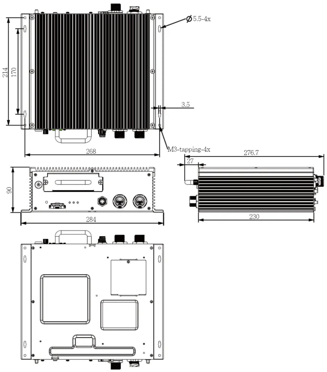
Interface Connectivity
Front Panel
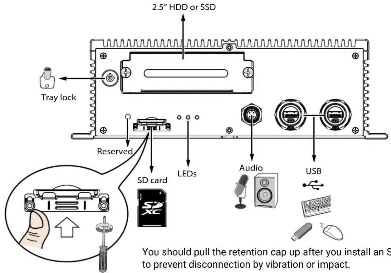
You should pull the retention cap up after you install an SD card to prevent disconnection by vibration or impact.
Note that the front panels of the NV9311P/NV9411P and the M12 version (NV9311P-M12/NV9411P-M12) are identical.
Rear Panel - NV9311P & NV9411P
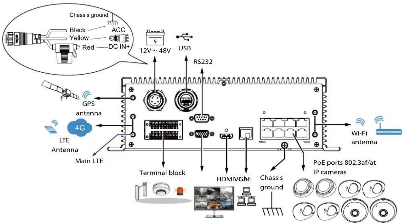
802.3af/at, total power budget is 64W.
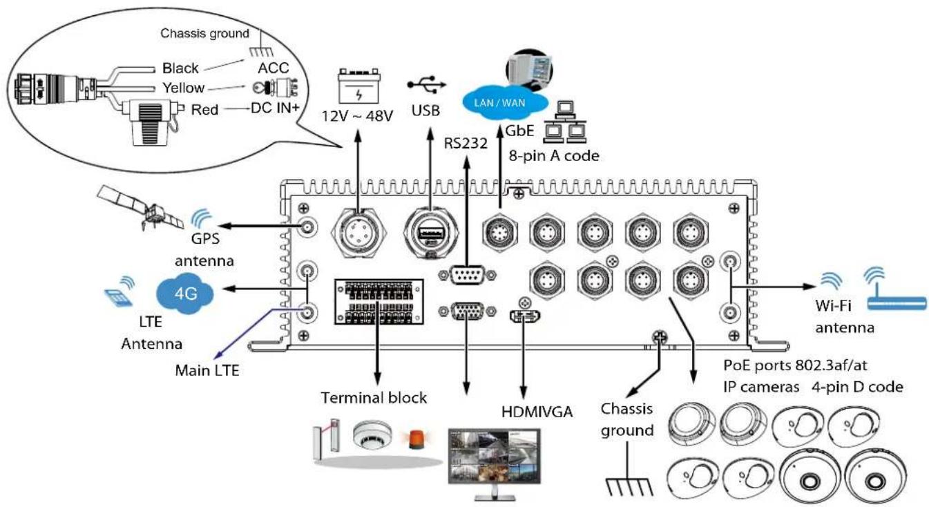
Rear Panel - NV9311P-M12 & NV9411P-M12
flowchart
graph TD
    A["Chassis ground"] --> B["Black"]
    A --> C["Yellow"]
    A --> D["Red"]
    A --> E["DC IN+"]
    F["GPS antenna"] --> G["4G"]
    H["LTE Antenna"] --> I["Main LTE"]
    J["Terminal block"] --> K["HDMIVGA"]
    L["USB"] --> M["RS232"]
    N["GbE 8-pin A code"] --> O["LAN/WAN"]
    P["Wi-Fi antenna"] --> Q["Chassis ground"]
    R["PoE ports 802.3af/at IP cameras 4-pin D code"] --> S["HDMIVGA"]
    T["12V ~ 48V"] --> U["USB"]
    V["12V ~ 48V"] --> W["USB"]
    X["12V ~ 48V"] --> Y["USB"]
    Z["12V ~ 48V"] --> AA["USB"]
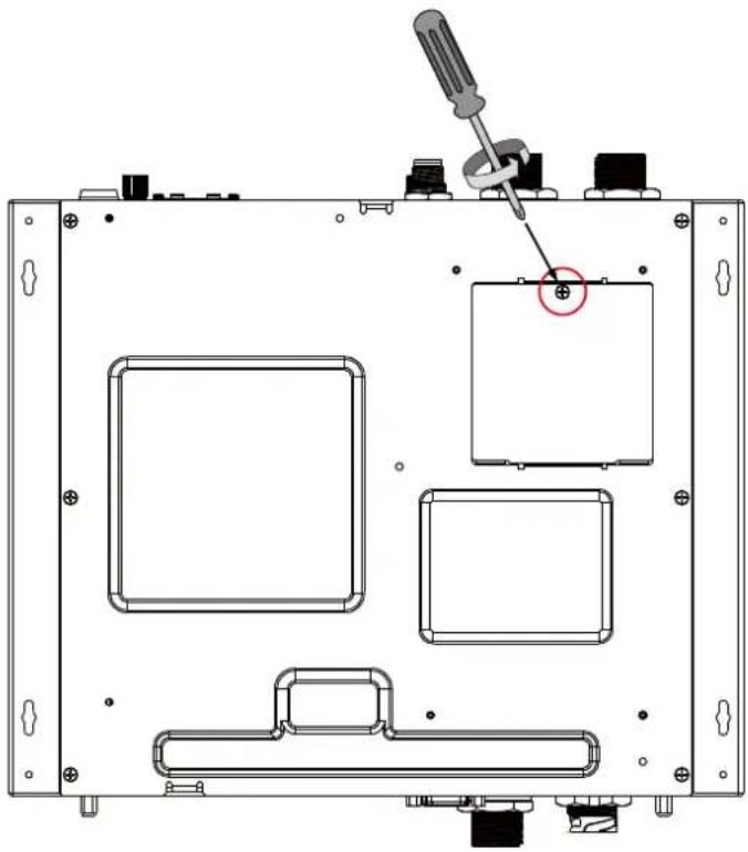
SIM card: Access from the Bottom
The GPS (Global Positioning System) connectivity can apply for speed and route tracking data on video streams. For specialized wireless transmission, a SIM card is necessary for the LTE module. The SIM card can be installed by opening a small cover from the bottom of the NVR.
natural_image
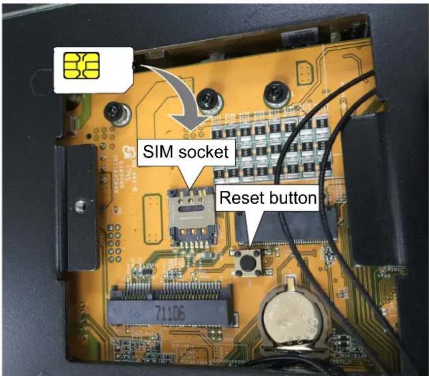
Technical line drawing of an electronic device casing with internal compartments and a screwdriver inserted (no text or symbols)The SIM socket.
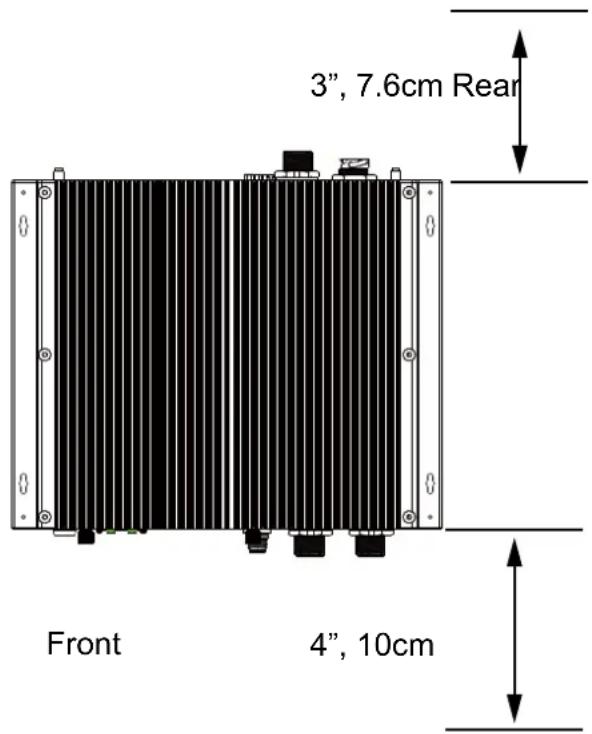
Cabling Clearance
It is recommended to have a clearance for making the cabling connections at the front and the rear of the chassis. Front: 4", Rear: 3".
Connector Pinouts-Front Panel
Audio IN/OUT-M12
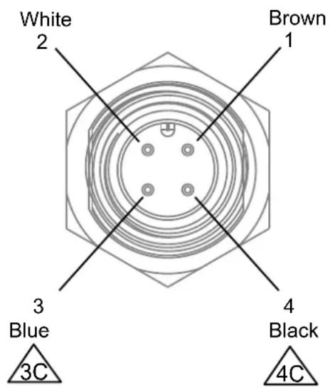
| Wire Color NOTE | |
| Brown GND | |
| White GND | |
| Blue Line out | |
| Black MIC in |
Connector Pinouts-Rear Panel
Terminal Block
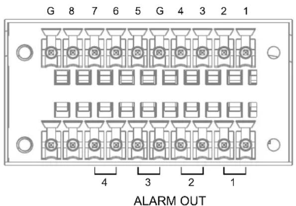
| 10 8 8 7 6 5 4 3 2 | 1 | |||||||
| DI GND DI8 DI7 DI | 6 DI5 DI GND DI4 | DI3 DI2 DI | 1 | |||||
| 20 19 18 17 16 15 | 14 13 12 11 | |||||||
| N/A N/A DO4_ | COM | DO4_NO | DO3_COM | DO3_NO | DO2_COM | DO2_NO | DO1_COM | DO1_NO |
Terminal Block Connections
The terminal block pinouts is shown as follows:
Connect your relay or external devices' signal wires to the system, the system will automatically detect the current signal status. You can then trigger the external devices using the DI/DO panel on the live view.
You can also configure the system alarm setting for the system to automatically trigger a DO on the occurrence of system events. See Alarm settings on page 107.
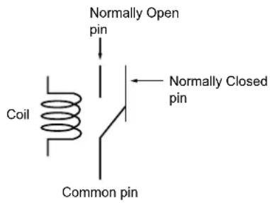
The pins are listed and described from left to right as shown in the drawing above.
| Pin Description NOTE | ||
| DI no. 1 ~ 8 Open/short to GND | ||
| G Pins #1~4 share a common ground.Pins #5~8 share a common ground. | ||
| NO | Normally open. Use the DO trigger buttons on the live view window to trigger the digital output. | |
| COM | Common pin | |
RS232
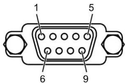
| 1 2 3 4 5 | 6 7 8 9 | |||||||
| N/A RXD | TXD DTR GND DSR RTS CTS N/A | |||||||
VGA
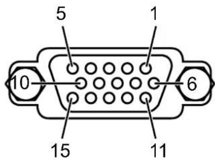
| 5 4 3 2 1 | ||||
| GND GND | B G R | |||
| 10 9 8 7 6 | ||||
| GND VGA | 5V GND GND GND | |||
| 15 14 13 12 | 11 | |||
| SCL Vsync | Hsync | SDA | GND |
Power Input
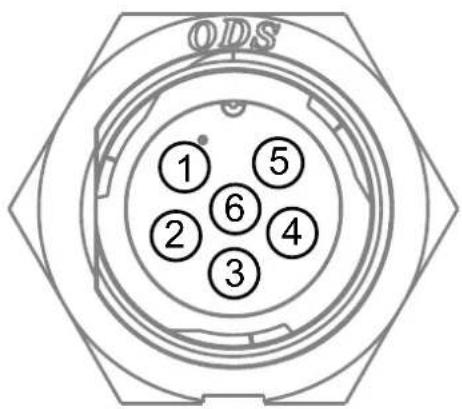
| 1 | 2 | 3 | 4 | 5 | 6 |
| DC IN+ | DC IN+ | ACC | DC IN- | DC IN- | DC IN- |
The Red DC IN+ connects to the vehicle battery positive.
The Black DC IN- connects to the vehicle battery negative or chassis ground.
The Yellow ACC connects to the ACC pin of the vehicle ignition key switch.
M12 8-pin A code Ethernet
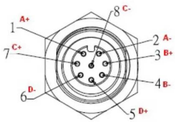
M12 4-pin D code Ethernet
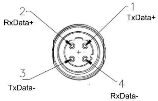

IMPORTANT:
While routing the cables, the possible damage caused by impact, friction, and vibration should be taken into consideration.
Cable Pinouts
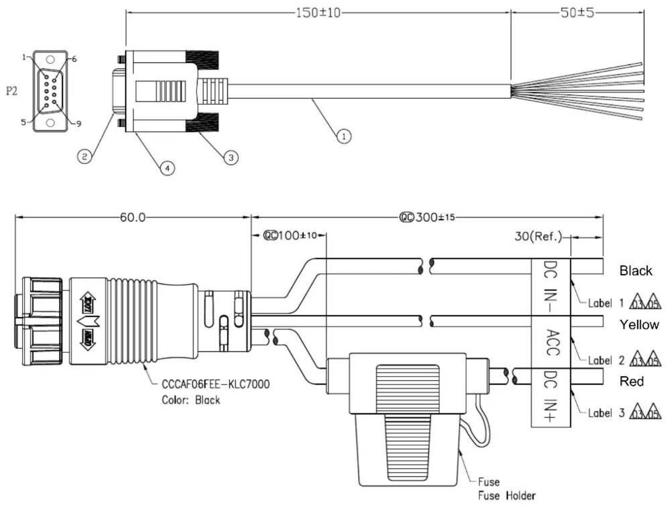
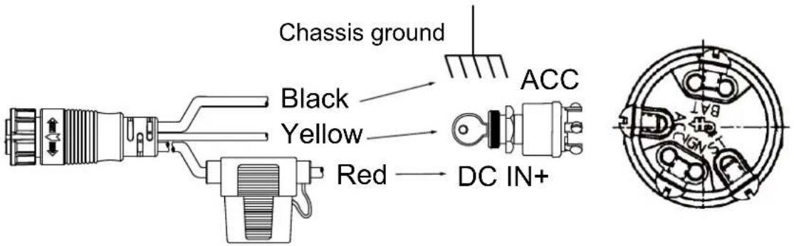
Connect the yellow wire to a vehicle's ignition switch's ACC pin. Red wire to the vehicle battery output, and the Black wire to the chassis ground.

IMPORTANT:
You can connect the wiring through the vehicle electrical panel. When connecting to the chassis ground, it is important that you are connecting to a grounding point that is not rusted. If connecting to a non-steel ground screw, resistance can be high causing problems with voltages supply.
Do not make ground connections to screws with thread locker compounds. They are insulated from the chassis. Screws with thread sealers or those mounted on gaskets are not the good choice for grounding.
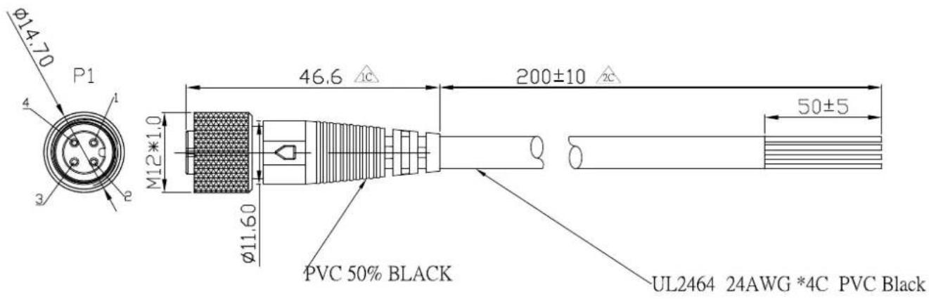
| P1 | WIRE COLOR | NOTE |
| 1 | BROWN | GND |
| 2 | WHITE | GND |
| 3 | BLUE | LINE OUT |
| 4 | BLACK | MIC IN |

RF Antenna Connector
The NVR has 3 antenna connectors, one of which is the GSM/UMTS/LTE main antenna connector, the others are UMTS/LTE auxiliary antenna connector and GPS/GLONASS antenna connector. The Rrecommended antenna characteristics are described by the 2 following tables.
Recommended Passive Antenna Characteristics
| Passive Recommended standard | |
| Direction omnidirectional | |
| Gain >-3dBi (avg.) | |
| Input impedance 50 ohm | |
| Efficiency >50% | |
| VSWR <2 | |
Recommended Active Antenna Characteristics
| Band Performance | ||
| TRP TIS | ||
| GSM850 ≥ | 29dBm ≤ -104dBm | |
| EGSM900 ≥ | 29dBm ≤ -104dBm | |
| DCS1800 ≥ | 26dBm ≤ -104dBm | |
| PCS1900 | ≥ 26dBm ≤ -104dBm | |
| WCDMA B1 | ≥ 19dBm ≤ -104dBm | |
| WCDMA B2 | ≥ 19dBm ≤ -104dBm | |
| WCDMA B5 | ≥ 19dBm ≤ -104dBm | |
| WCDMA B8 | ≥ 19dBm ≤ -104dBm | |
| LTE B1 | ≥ 18dBm ≤ -92dBm | |
| LTE B2 | ≥ 18dBm ≤ -90dBm | |
| LTE B3 | ≥ 18dBm ≤ -89dBm | |
| LTE B4 | ≥ 18dBm ≤ -92dBm | |
| LTE B5 | ≥ 18dBm ≤ -90dBm | |
| LTE B7 | ≥ 18dBm ≤ -90dBm | |
| LTE B8 | ≥ 18dBm ≤ -89dBm | |
| LTE B13 | ≥ 18dBm ≤ -89dBm | |
| LTE B17 | ≥ 18dBm ≤ -89dBm | |
| LTE B18 | ≥ 18dBm ≤ -92dBm | |
| LTE B19 | ≥ 18dBm ≤ -92dBm | |
| LTE B20 | ≥ 18dBm ≤ -89dBm | |
| LTE B38 | ≥ 18dBm ≤ -92dBm | |
| LTE B39 | ≥ 18dBm ≤ -92dBm | |
| LTE B40 | ≥ 18dBm ≤ -92dBm | |
| LTE B41 | ≥ 18dBm ≤ -91dBm | |
Installation
Install a SIM card
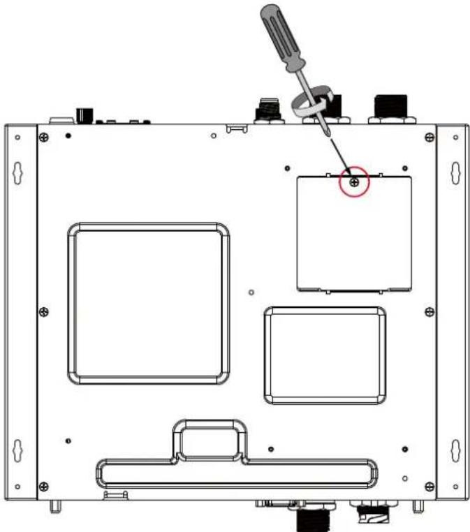
Open the small maintenance panel at the bottom of the NVR. You should subscribe to a service with a wireless service provider and obtain a SIM card.
natural_image
Technical diagram of an electronic device chassis with labeled components and a screwdriver inserted (no text or symbols present)Refer to page 134 for the Network IP and the default gateway configuration.
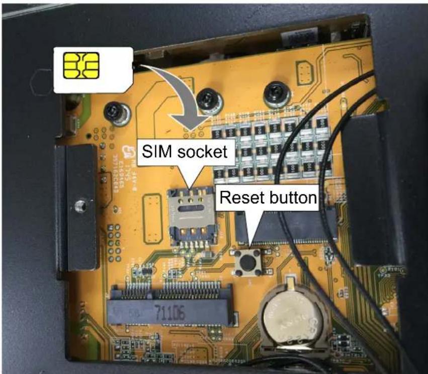
Install a SIM card to the SIM socket. The reset button is also located in here.
Install an LTE and Wi-Fi module
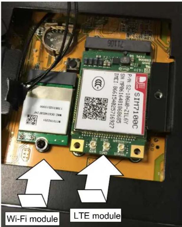
Depending on the country/region of your operation, you may need to install different wireless WAN modules. Install an LTE and Wi-Fi module by lowering and inserting them into socket.
Secure the installation by driving 3 screws.
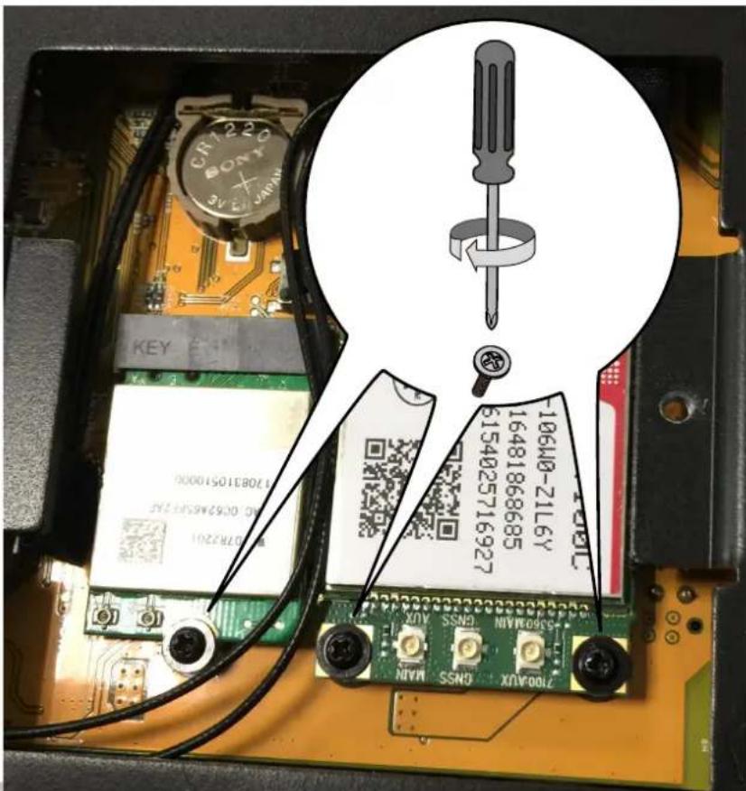
Connect the antenna cables (provided with the NVR) to the corresponding connectors on the module. Note that only the Main and AUX connectors on the PCI-E 4G communication module need to be connected. The NVR comes with another embedded GPS module. Connect the antenna cables to the Wi-Fi module.
The SIM7100C PCI-E 4G communication module is shown here as an example.
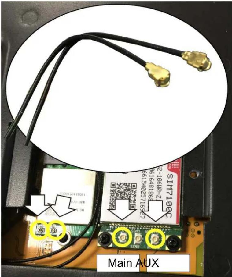
Note that the Wi-Fi and 4G network configuration windows will only be available when the associated modules are installed in the NVR. See page 134 for information of the configuration.
Intall a 2.5" hard disk or SSD
Note the choice with HDD or SSD is relted to operating temperature: -40°C \~ 55°C(SSD), 0°C \~ 55°C (surveillance HDD).
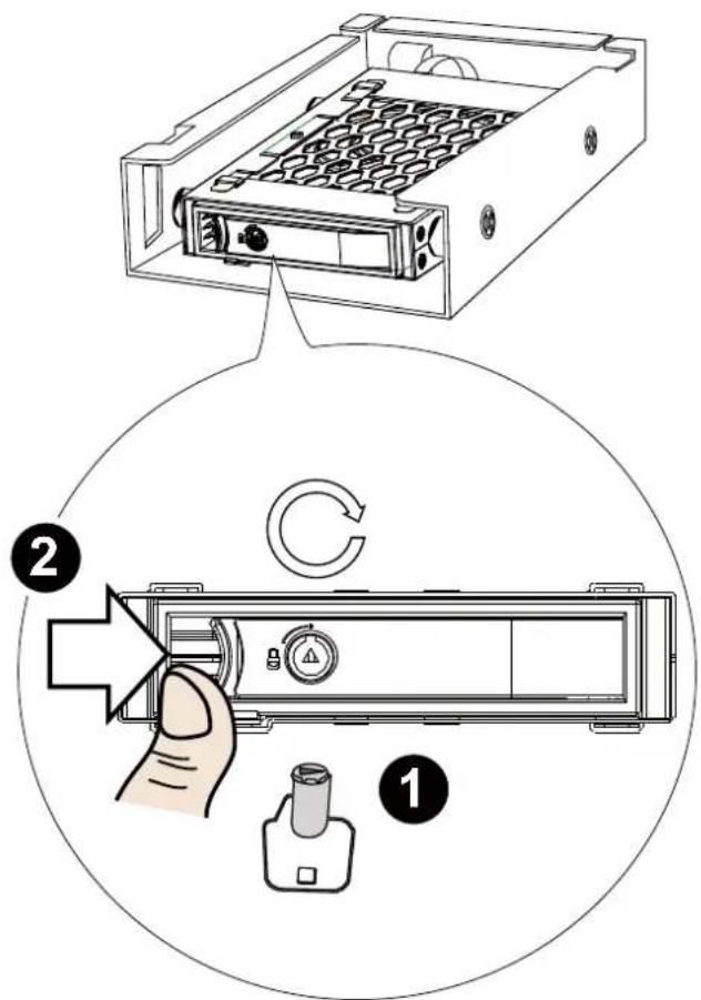
- Use the bezel key to unlock the bezel lock.
- Loosen the hand screws.
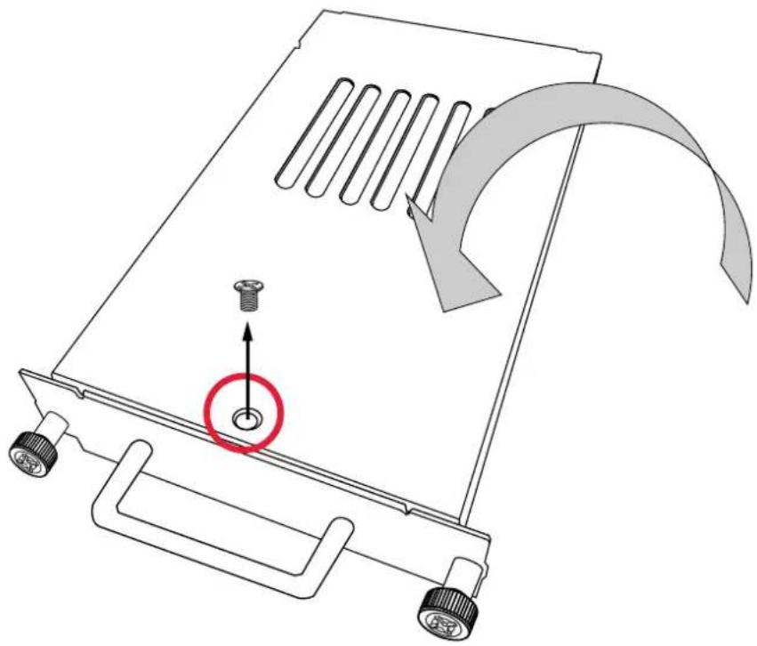
- Remove the tray box.
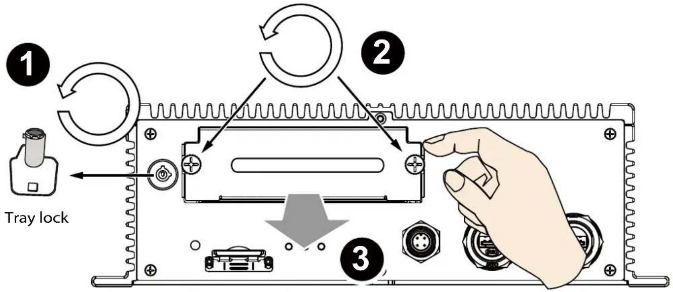
- Remove 4 flat sunk-head screws from the top of the tray box.
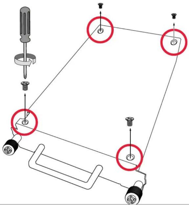
- Remove another screw from the bottom of the tray box.
natural_image
Diagram of a mechanical device with a screw and directional arrow indicating motion (no text or symbols)- The interior of the box is revealed. Remove the drive tray by unlocking the tray lock and press lever to the right.
- Pull the drive tray away from the tray box.
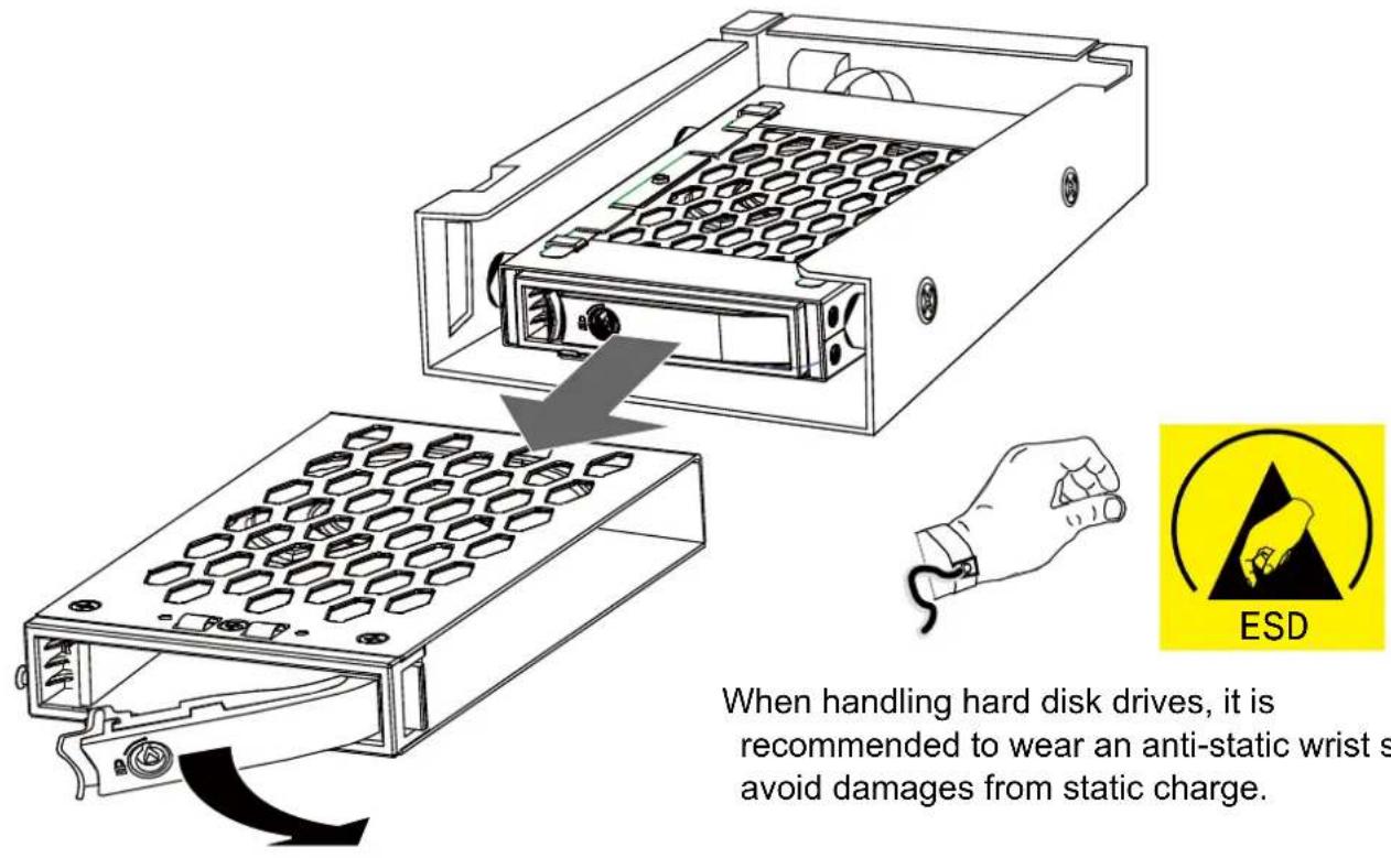
When handling hard disk drives, it is recommended to wear an anti-static wrist strap to avoid damages from static charge.
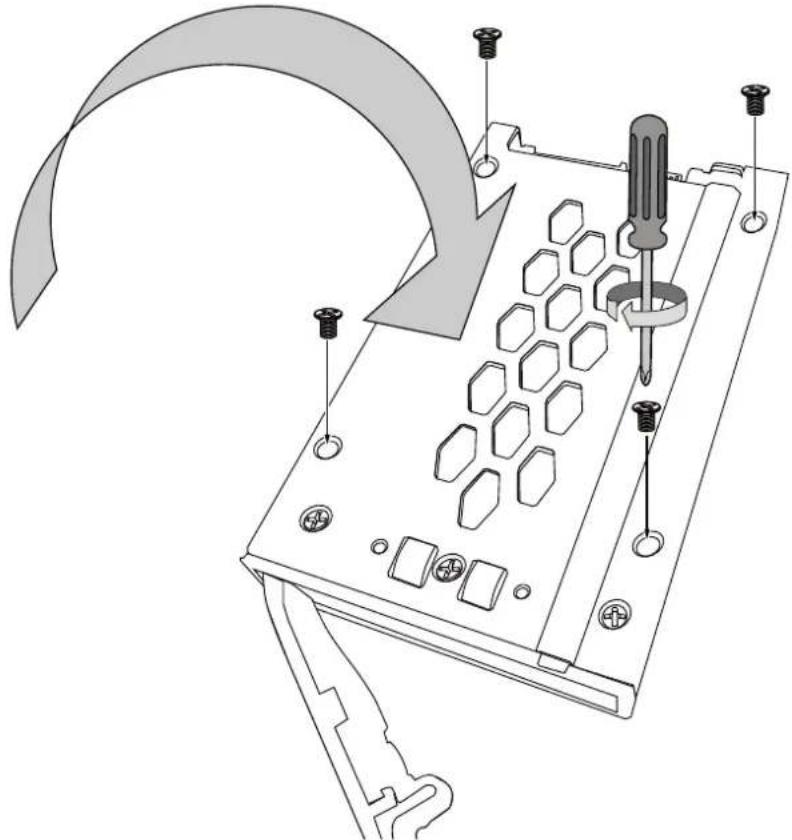
- Insert the 2.5" hard disk or SDD into the drive tray through the side opening. Note that the hard disk label side is facing up and the SATA connector is at the rear side.
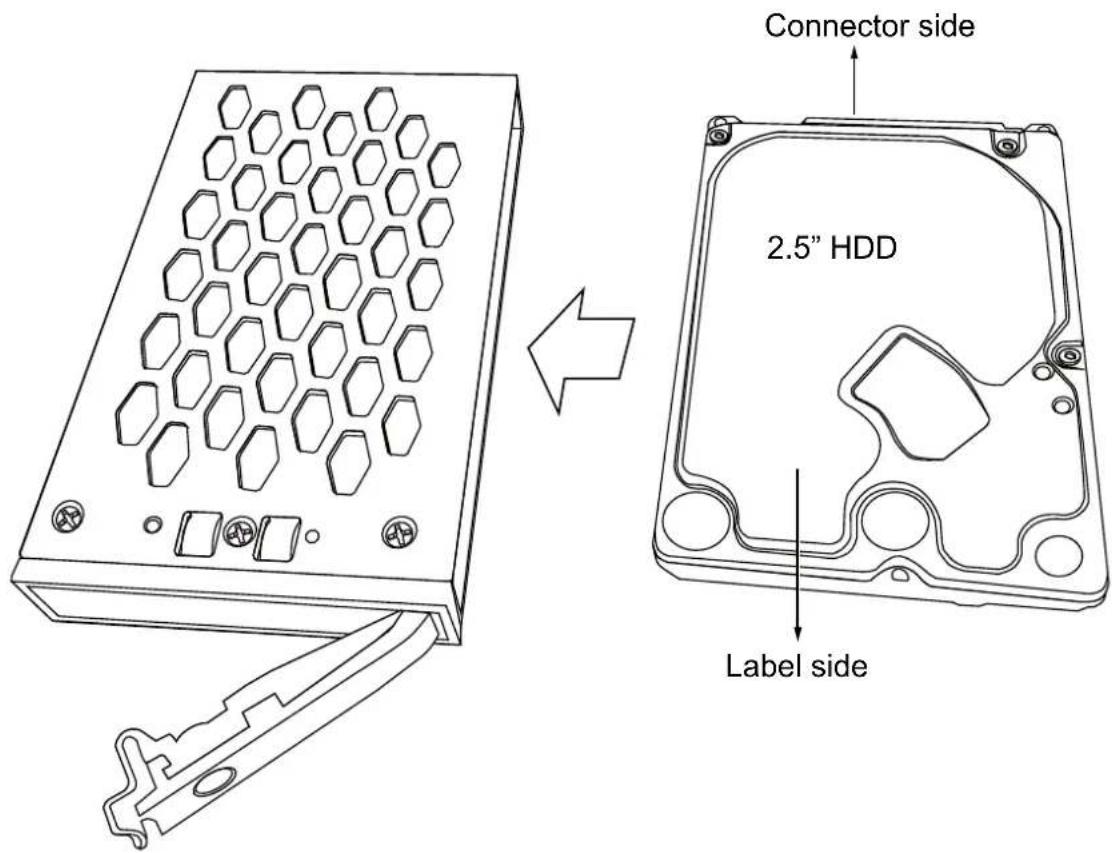
- Flip the drive tray over, and secure the hard drive using 4 included sunk-head screws.
natural_image
Diagram of a computer RAM module with screwdriver and socket, showing internal components and mounting hardware (no text or symbols)- When done, install the drive tray into the tray box. Note that the lever should be in the open position when you insert the drive tray.
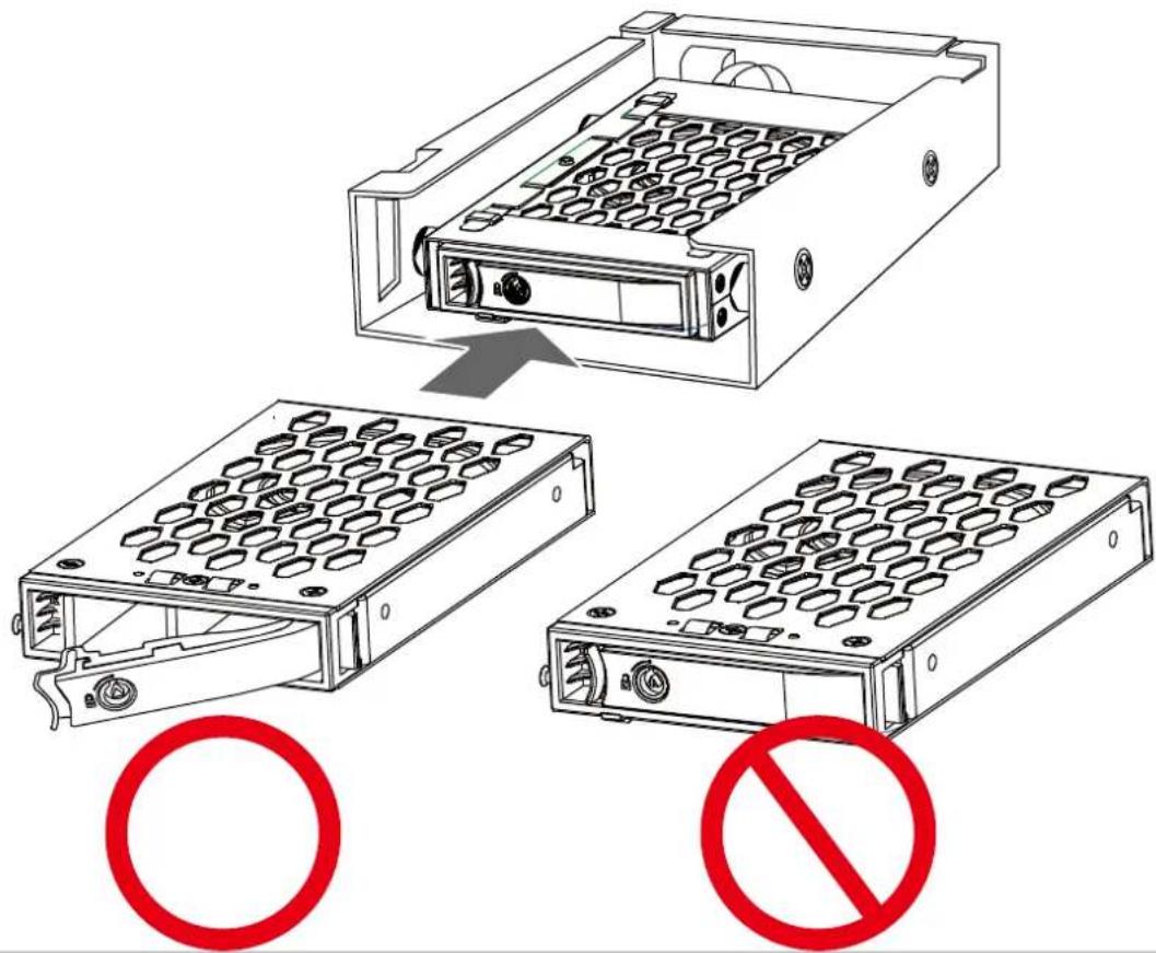
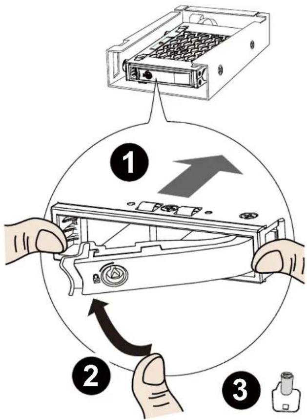
10-1. Press the drive tray firmly into the unit bay. Contact resistance can be felt during the process.
10-2. Close the front lever.
10-3. Secure the installation using the tray lock. Keep the tray lock key safe for later use.
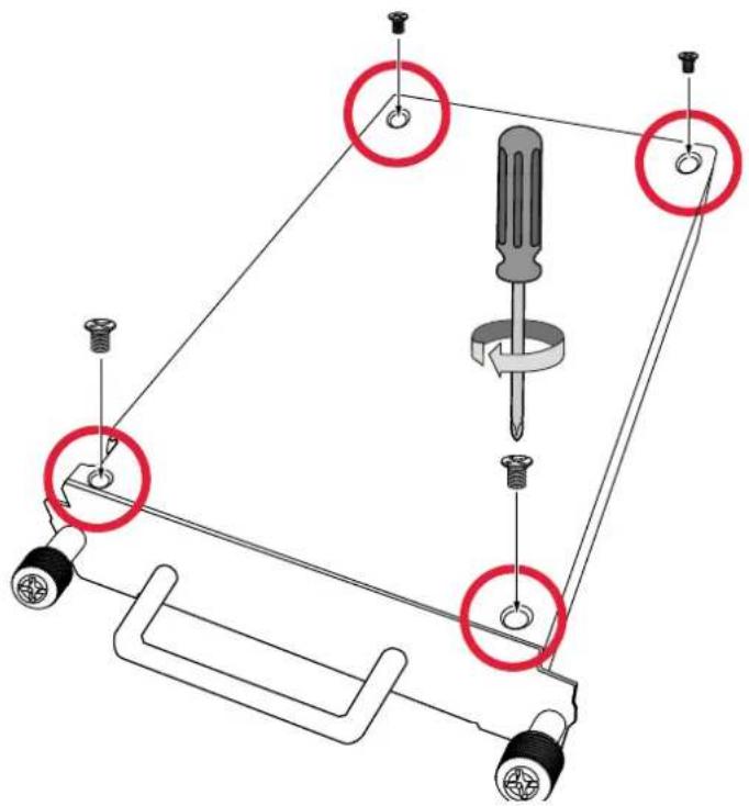
- Install the tray box cover by fastening 5 screws you just removed.
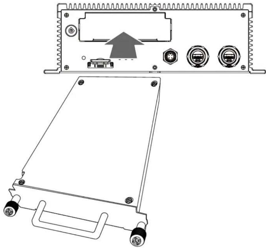
- Install the tray box back into the NVR.
natural_image
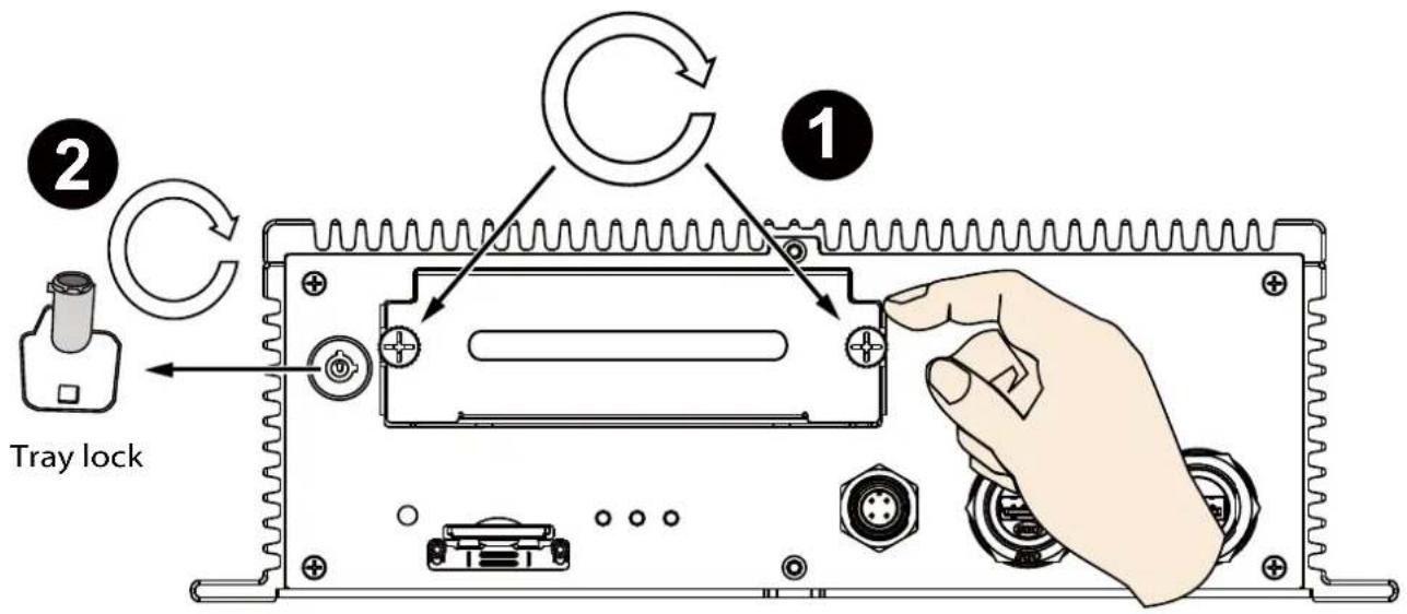
Technical line drawing of an electronic device rear panel with ports and a handle, showing no text or symbols.- Secure the installation by fastening hand screws and lock the tray lock on the front panel. NOTE that you cannot power up the device unless the tray lock is locked!
- Skip this section (steps #14 to #17) if you install the NVR with the M12 connectors.
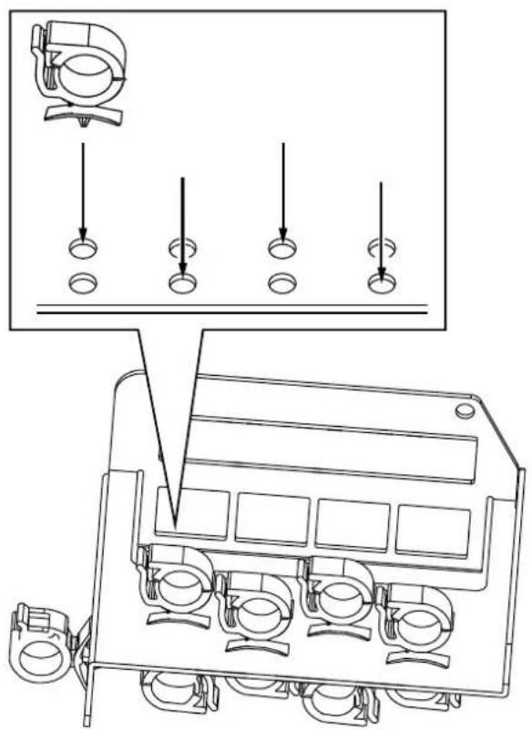
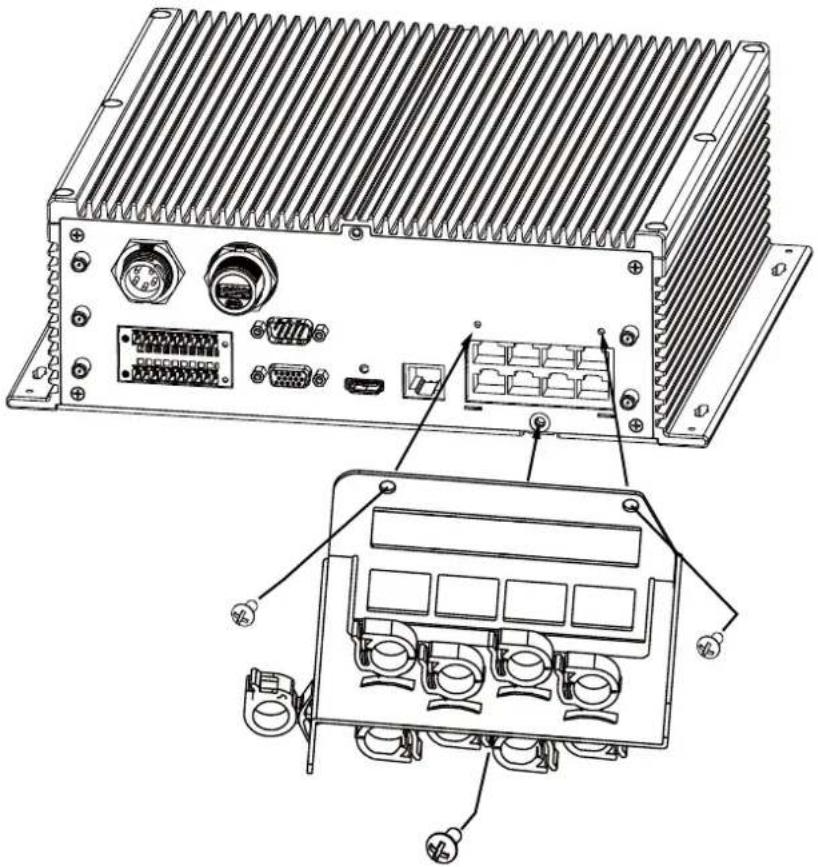
Install the cable clamps to the cable retention bracket. Note that the positions of every two cable clamps should be one in the back and the other in the front. The same applies to the holes at the bottom.
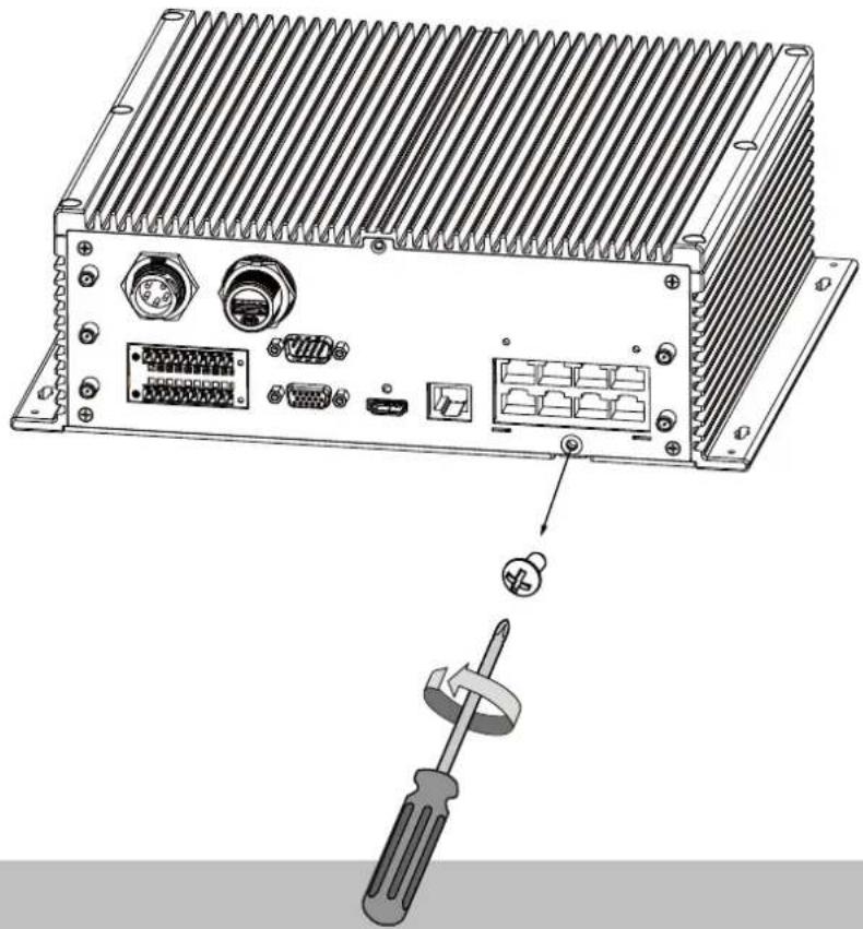
- Remove the grounding screw. Keep it for later use.
natural_image
Diagram of an electronic device rear panel with connectors and a screwdriver inserted (no text or labels)- Secure the bracket to chassis using two screws at the top, and the grounding screw at the bottom.
natural_image
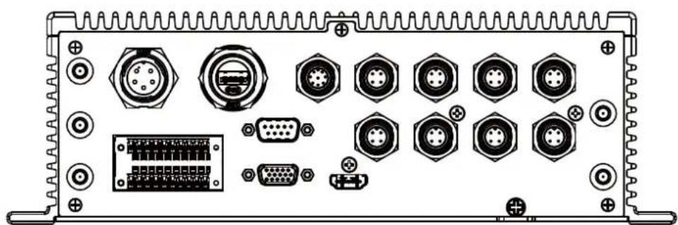
Technical line drawing of an electronic device rear panel with connectors and ports (no text or symbols)- Connect cables to ports and secure their connections using the cable clamps.
natural_image
Back panel of an electronic device showing various connectors and ports (no text or labels visible)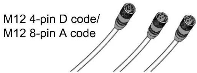
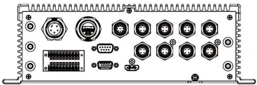
Shown below is the M12 rear panel connection.
natural_image
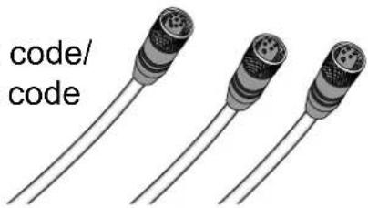
Back panel of an electronic device showing various ports and connectors (no text or symbols visible)M12 4-pin D code/
M12 8-pin A code

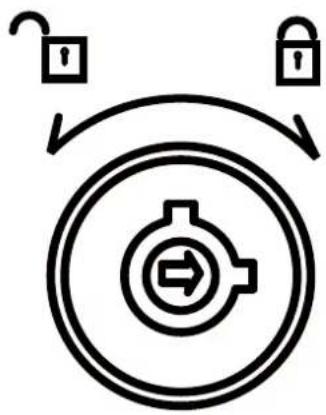
IMPORTANT:
The tray lock must be in the locked position before the NVR can be powered on. Make sure you keep your tray keys for access to the onboard disk drive.
flowchart
graph TD
    A["Lock Icon"] --> B["Target Icon"]
    C["Lock Icon"] --> B
    B --> D["Return Arrow"]
    style B fill:#f9f,stroke:#333
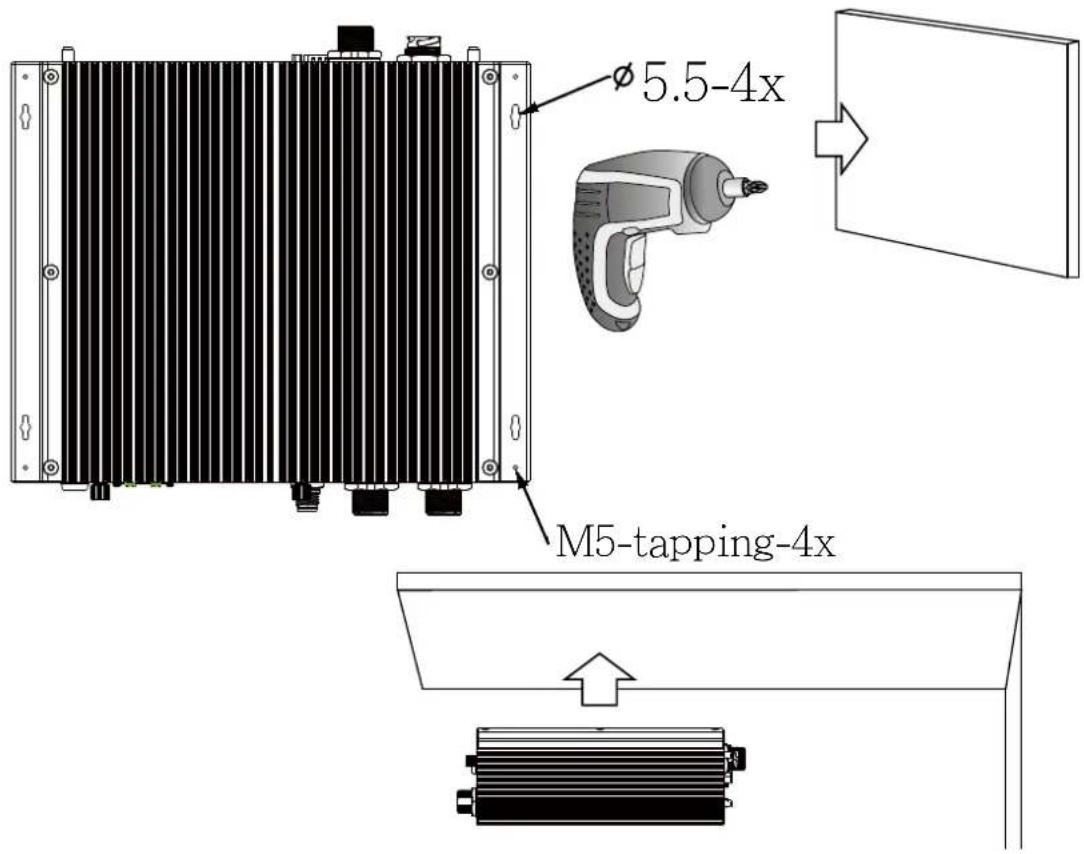
- Use four self-tapping screws to secure the NVR to a metal panel. If the need should arise to install the NVR on a ceiling, use the M5 self-tapping screws and drive them through the smaller holes on the four corners of the NVR.

Initial Configuration—via a Local Console
A local console requires the following:
- A monitor is connected via an HDMI or VGA cable.
- A mouse and/or a keyboard are connected to the system.
- It is presumed that the system has not been configured yet.
Follow the onscreen messages to complete the initial configuration:
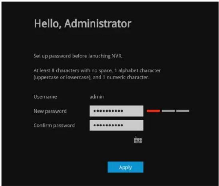
- The NVR is started when the vehicle engine is started. When started for the first time, you will be required to configure a system password. Jot down the password, and enter it twice to access the system.
- Select the UI language, Time zone, and current date and time. Click on the Continue button to proceed.
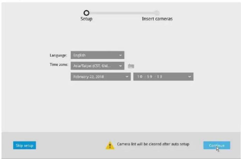

IMPORTANT:
Except in the initial setup, changing system time can produce disruptions to the existing recordings. Turning the current system time back to a time when video recording was taking place can generate duplicate files. And those files may not be playable.
- The system will then start to scan the local subnet for connected cameras.

Search for cameras

- All cameras detected on the network will be automatically selected. If necessary, deselect the cameras you want to exclude from the configuration. Click Finish to proceed.

3 cameras found
| Unselect all | IP | MAC | Model | Port | Channel |
| 169.254.105.186 | 00-02-D1-39-6A-BA | FD9171-HT | 80 | 1 | |
| 169.254.33.11 | 00-02-D1-5C-1A-84 | FE3391-EV | 80 | 1 | |
| 169.254.102.8 | 00-AB-CD-83-66-08 | MD8565-N | 80 | 1 |


NOTE:
- The maximum recording bandwidth is
1920x1080 @ 480 fps (16-CH)
Max. Decoding streaming resolution: 8192x8192
Display resolution:
for H.264/MJPEG, 4096x4096 for H.265
HDMI: 3840x2160, 1920x1080, 1280x720(P2)
VGA:1920X1080,1280x720(P2)
When cameras are recruited into the configuration, their stream 1 is used as the recording stream.
The resolution and fps (frame rate per second) of stream 1 may vary depending on the specifications of different cameras.
- If there are more than 16 or 32 cameras in your local network, you will need to manually select cameras.
If there are less than 8 or 16 cameras, the Auto Setup will automatically move to the next configuration step. - The maximum streaming bandwidth is 96Mbps. If multiple web consoles, VAST, or iViewer connections are being made and the threshold is exceeded, the new connection requests will be rejected.
- The system will automatically create a volume from the installed disk drive. If your cameras come with preset password, enter "root" as the user name, and the preset password in order to join the cameras to your configuration.
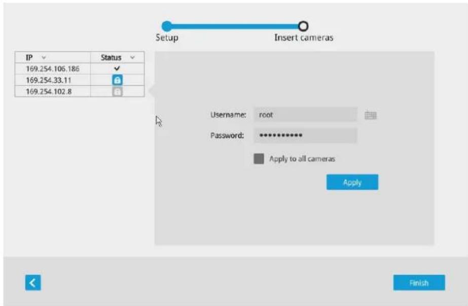
- When done, the next screen will be the NVR's liveview page.
LED Indicators
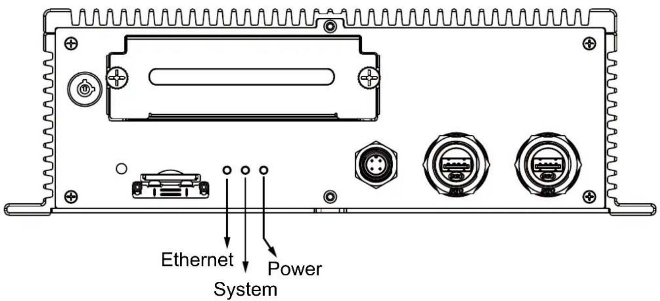
| Name Behavior Definitions | |||
| Power LED 1 | Solid | Green Power on | |
| 2 Green OFF Power off | |||
| 3 Blinking Green every 1 second | The delay shutdown is taking place. | ||
| 4 No ACC LED is off | |||
| * Below is used when unable to power up | |||
| 5 HDD tray unlocked | LED blinks every 2 seconds. | ||
| 6 Low voltage LED blink | ks twice 0.5 sec. apart. Repeats after 2 sec. | ||
| 7 Power on delay LED | blinks 3 times 0.5 sec. apart. Repeats after 2 sec. | ||
| 8 Heater on LED blinks | 4 times 0.5 sec. apart. Repeats after 2 sec. | ||
| 9 Abnormal temperature | LED blinks 5 times 0.5 sec. apart. Repeats after 2 sec. | ||
| Status LED 1 | Solid | Green System is ready. | |
| 2 Blinking Green every 1 second | Updating firmware or device pack. | ||
| 3 Solid Red S.M.A.R.T. | -related disk errors, or a configured H.D.D. is missing, or H.D.D. is full. Buzzer will also be sounded. When buzzer is turned off, LED will return normal. | ||
| NET LED | 1 | Blinking Orange | Transmitting and receiving data. |
| 2 OFF Ethernet is disconnected. | |||
Power Up and Power Down
To power up and power down,
On the initial configuration:
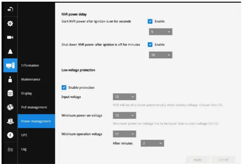
The NVR is started when the vehicle ignition is started sensing the voltage. The NVR supports configurable power ON/OFF delay time. Low power protection is also supported. See page 125 for the delayed ON/OFF configuration (see Settings > System > Power management).
After the initial connection,
When the vehicle engine stops, the system should start flushing the cached contents in system memory and gracefully shut down. The NVR can be configured to power down later than the engine stop using the battery power.
Press the Reset button for longer than 5 seconds can restore system defaults.
| Min. power on voltage (A) Min. operating voltage (B) | ||
| Disabled (default) 9 9 | ||
| 12V 11.5~12.5, default | It 12 10.5~11.5, default 11 | |
| 24V 23.5~24.5, default | It 24 22.5~23.5, default 23 | |
| 36V 35~37, default 36 | 34~35, default 34.5 | |
| 48V 47~49, default 48 | 46~47, default 46.5 | |

IMPORTANT:
The NVR supports low battery power detection and automatic power-down when voltage drops below a configurable threshold.
See page 125 for information about Power management.
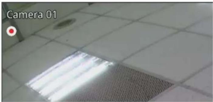
When a camera is included into the NVR configuration, the video recording automatically starts. The red dot indicates the recording is taking place.

IMPORTANT:
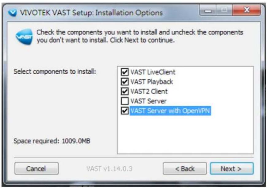
For making Internet connection via the NAT-traversal over the OpenVPN tunnel, see page 141 for details. You can also refer to VAST2 User Guide for details.
To enable VPN tunneling, when you install VAST2, select VAST server with OpenVPN.

NOTE:
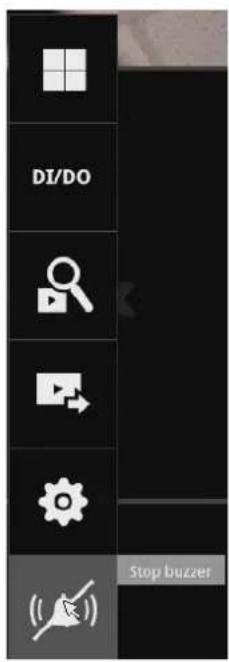
If system buzzer is sounded, move your mouse cursor to reveal the main screen portal, and then click on the Stop buzzer button.
Serious system faults, such as a missing volume, can trigger the system buzzer. Verify the cause of system fault and turn off the buzzer.
Section One
Management over a Local Console
Chapter Two
Introduction to the Local Console Interface
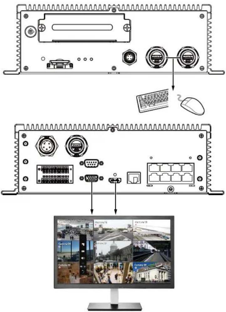
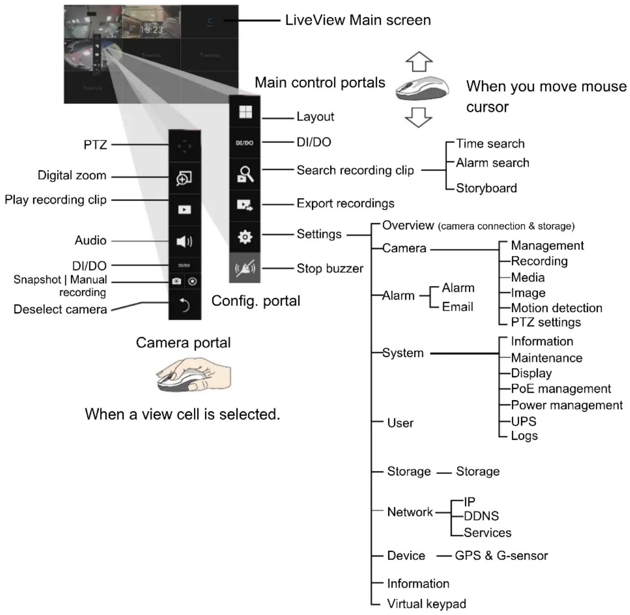
By default, a live view appears on an HDMI monitor. The interface architecture of the local console is illustrated as follows:
flowchart
graph TD
    A["LiveView Main screen"] --> B["Main control portals"]
    B --> C["When you move mouse cursor"]
    C --> D["Config. portal"]
    D --> E["Camera portal"]
    E --> F["When a view cell is selected."]

    subgraph Top
        G["PTZ"] --> H["Digital zoom"]
        H --> I["Play recording clip"]
        J["Audio"] --> K["DI/DO"]
        L["Snapshot | Manual recording"]
        M["Deselect camera"]
    end

    subgraph Bottom
        N["Layout"] --> O["DI/DO"]
        P["DI/DO"] --> Q["Search recording clip"]
        R["Export recordings"] --> S["Settings"]
        T["Stop buzzer"] --> U["Overview (camera connection & storage)"]
        V["Camera"] --> W["Alarm"]
        X["Alarm"] --> Y["Email"]
        Z["System"] --> AA["User"]
    end

    style Top fill:#f9f,stroke:#333
    style Bottom fill:#ccf,stroke:#333
After you finish configuring using a Camera portal, click again on the camera view cell to reveal the main control portals.

IMPORTANT:
Due to the limitation of system resources, the fisheye dewarp (1R, 1P, 1O3R, 1O8R modes) can only take place on one view cell, for one fisheye camera.
For the Export recordings function, refer to page 85.
2-1. How to Begin
1. How to access the Configuration Portal?
Make sure a mouse is attached to your NVR. Move your mouse cursor, and the Configuration Portal will appear on screen. For all the configurable options available through this portal, please refer to Chapter 3 on page 73.

You can also hide these portal toolbar. Right-click on the liveView screen to display the option.
2. How to access the Camera Portal?
Single click to select a view cell, the Camera Portal will appear. The system automatically detects the characteristics of an individual camera when you select a view cell.

This portal appears with a camera that supports mechanical PTZ.

This portal appears with a camera that does not support mechanical PTZ.

Tips:
Here are some operation steps using the tool bar:
- Single-click to select a view cell and bring out the tool bar.
- Double-click to expand a view cell to the full view.
- Double-click again to shrink the view cell to the original size.
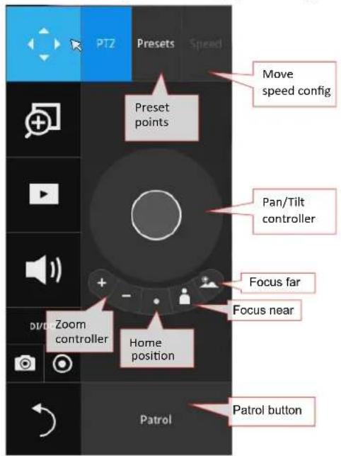
PTZ control panel for joystick type PTZ
PTZ control panel for ordinary PTZ type
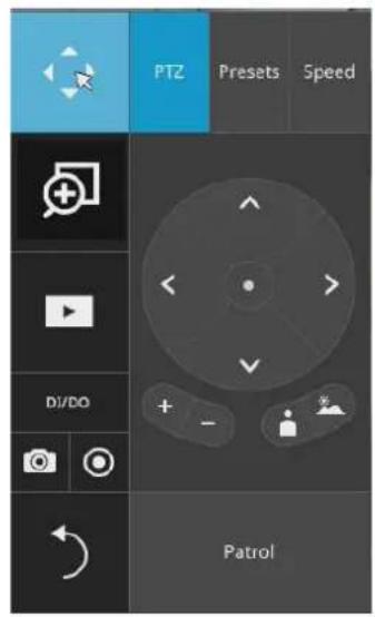
PTZ presets: If your PTZ cameras have preset locations, click on the button to unfold the preset menu. Click on any of the preset locations to move to the area of your interest.
Pan/Tilt controller: Pull the inner circle to the direction you prefer. Release the mouse button to stop moving.
Zoom controller: The zoom controller buttons only apply to cameras that come with an optical zoom module, such as a speed dome camera.
Focus controller: The focus controller buttons apply to cameras that come with focus control over its lens module, such as a speed dome camera.
3. How to retrieve and access recorded videos?
3-1. One is to access the video clips taken within 2 hours. Left-click to select a view cell, and then click on the Recording clips button.
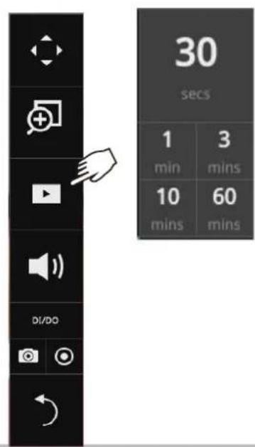
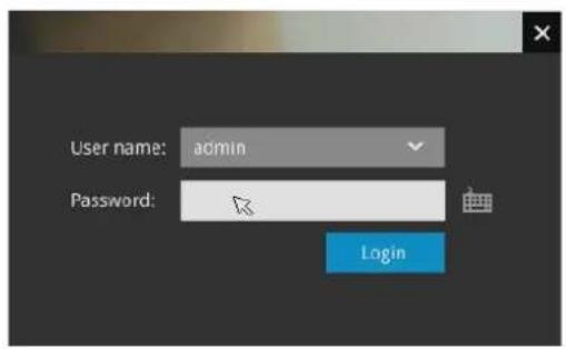
Select a time value by a single click. You will be prompted for User name and Password, enter admin and admin (the default user name and password), and then click Login.
The Playback window will prompt, and a playback begins from the point in time you selected, e.g., 30 seconds ago. This function allows you to quickly review what has just happened.
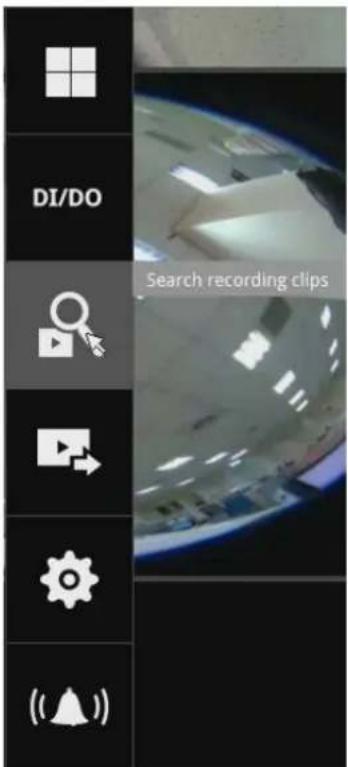
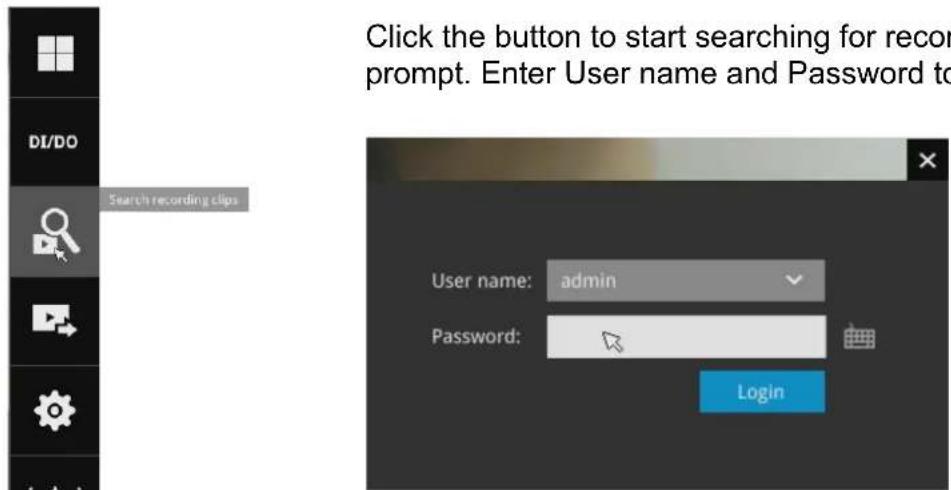
3-2. Another way to access past videos is to open the Search recording clips window. Move your mouse cursor to display the Configuration Portal (without selecting any view cell). Click on the Search recording clips button. Please refer to page 74 for more information about the search functions.
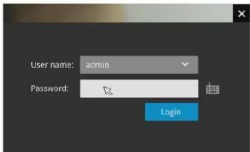
You will be prompted for User name and Password, enter admin and admin (the default user name and password) and click Login. It is highly recommended to change the password after you log in.
4. How to recieve system alarm?
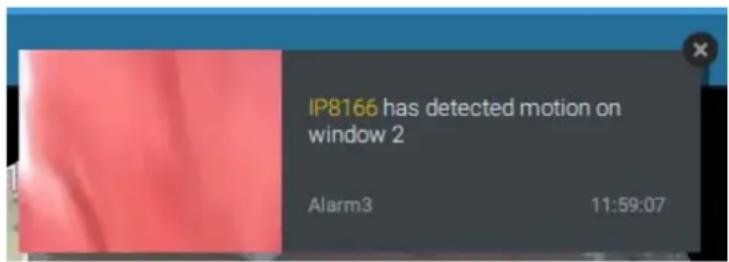
Please refer to page 107 for how to configure system alarm triggers. When the alarm is triggered, e.g., by digital inputs or motion detection, an alarm message will prompt on the screen.
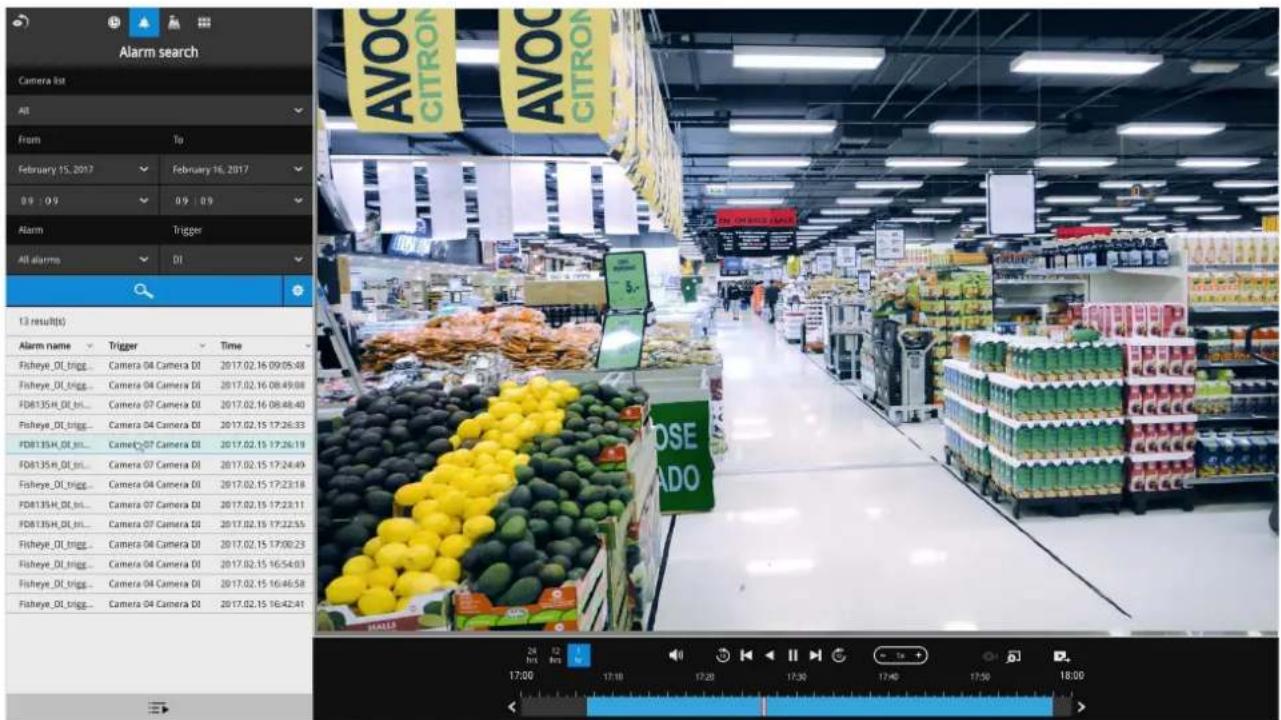
Click on the Alarm icon for an instant review of the event occurrences.
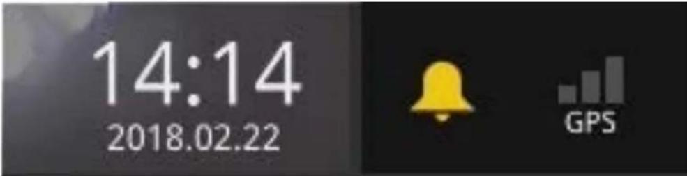
If the alarm is configured with video recording as the responding action, you can click on the alarm entry. The Playback window will appear, allowing an instant playback of the alarm-related footage. You will enter the "Search alarm results" page even if the alarm does not trigger a recording action.
5. Why live view is unavailable?
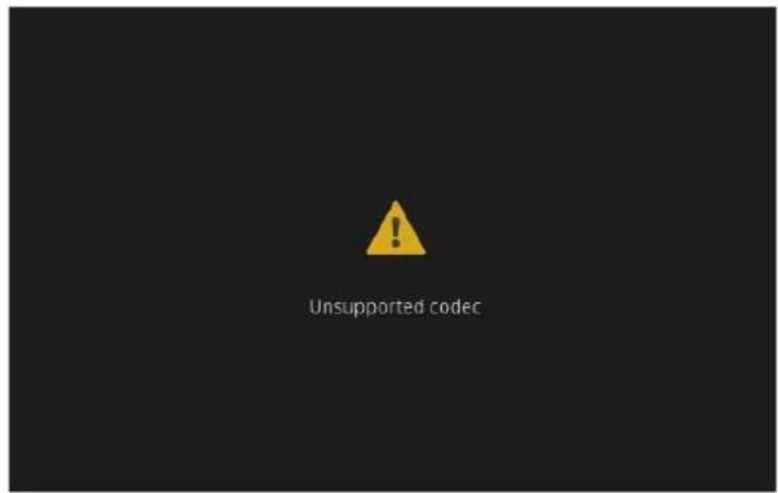
The default live view receives a camera's stream #1. If a camera's stream #1 is configured using MPEG-4 as the video codec, the following message will prompt.
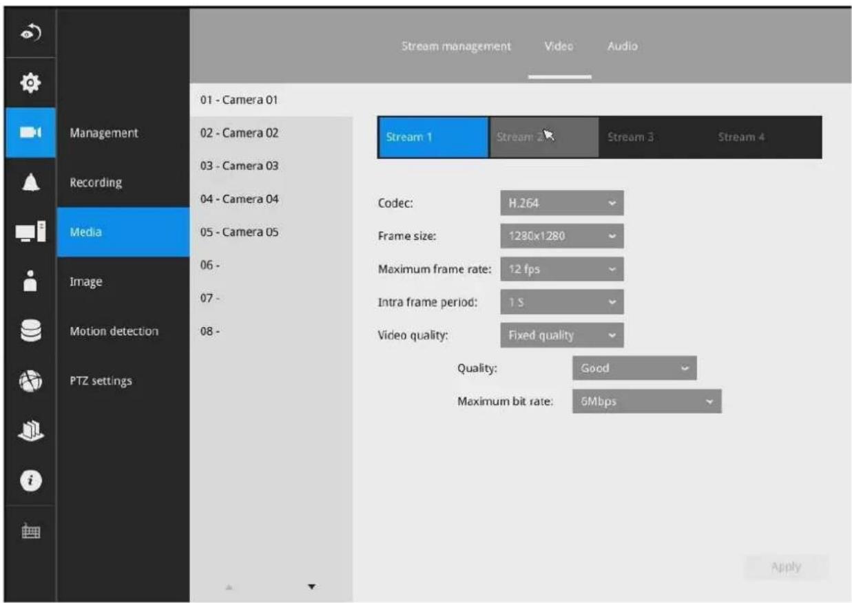
You can go to the Settings > Camera > Media > Video window to configure the video codec of stream #1 into H.264 or H.265.
6. How do I move to another layout page?
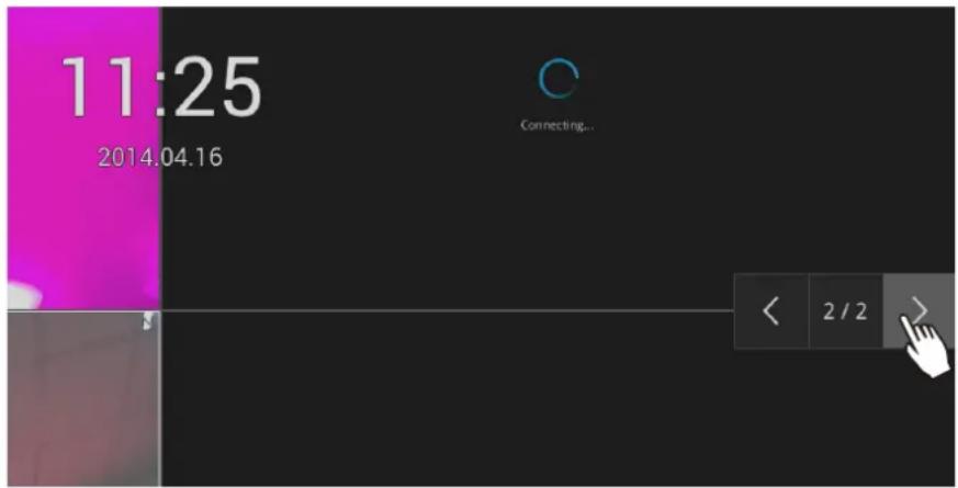
Move your cursor to the right-center side of your screen. The page turner buttons will appear as shown below.
For example, if you have 8 cameras placed on 2 2x2 layout pages, use these buttons to visit different pages.
7. Why the onscreen tool bars disappear after some time?
The system comes with idle modes. Below are the applicable conditions:
- Live view: if no management activities occur for 5 seconds, the tool bars disappear from screen. When in the idle mode, mouse cursor and tool bars will disappear. Moving the mouse cursor will re-activate the screen.
- Settings page: If left unattended for 10 minutes, system will automatically log out. The system will prompt for user credentials if a user tries to access the Settings page again.
- Search recording clips window: If currently there is a video playback, the system will not enter the idle mode.
2-2. Tracking and Viewing the Mobile NVR Videos on VAST2
2-2-1. Adding NVR as a VAST2 Sub-station
- From the Live view page, click Settings.
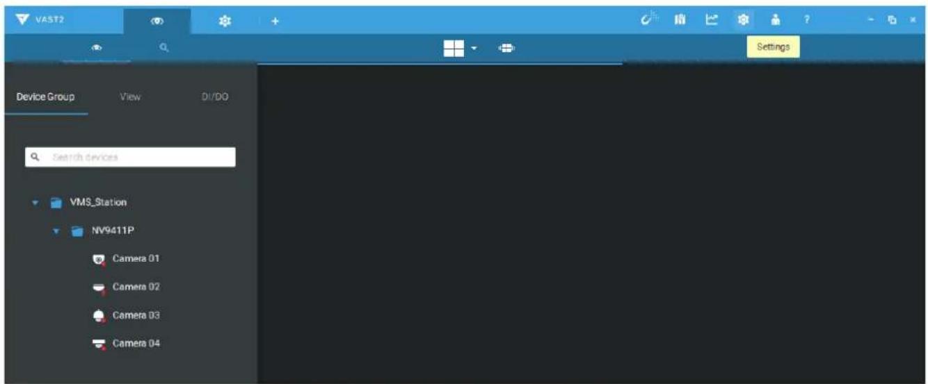
- Click Sites from the Device pane.
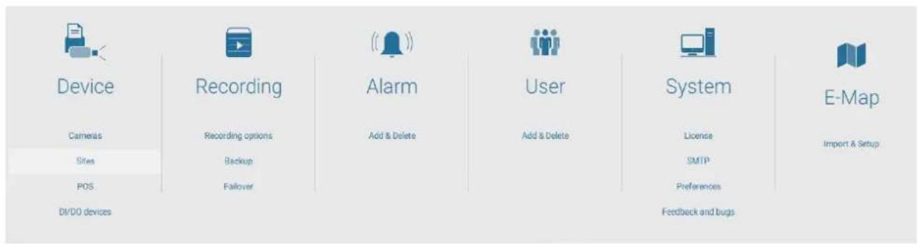
- In the Site management window, click the Add Sites button.
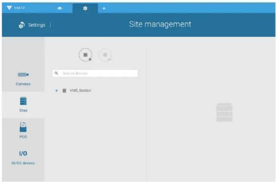
- You can manually enter the IP address or use the Search button to locate your NVR.
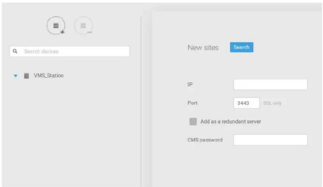
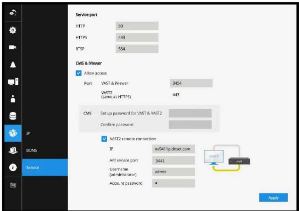
- Once the NVR is found, enter the CMS access password to authenticate the connection.
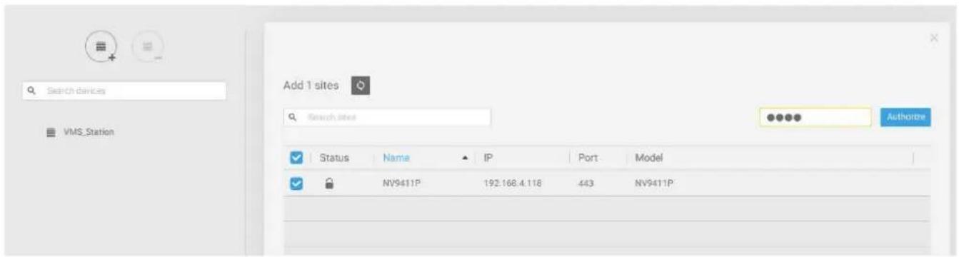
Note that the CMS password is configured on the NVR, in the Settings > Network > Service page.
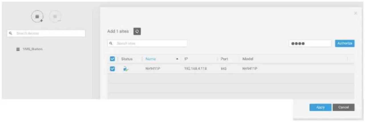
- A check mark will appear on the NVR entry. Click the Apply button to complete the configuration.
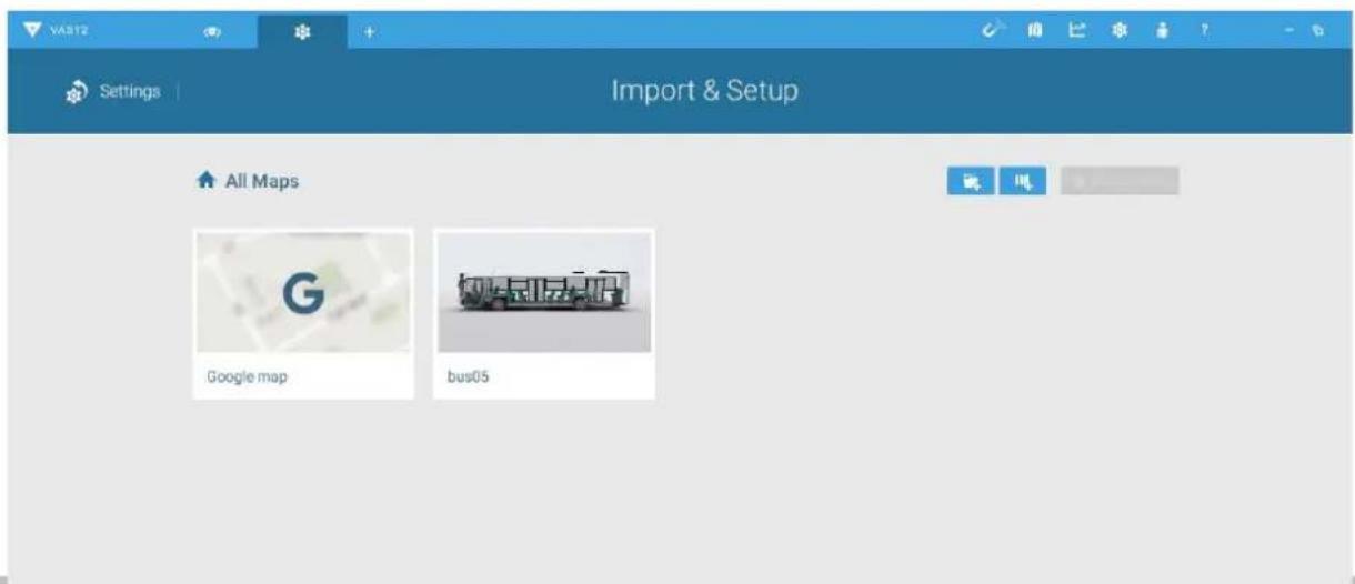
2-2-2. Configuring GPS and E-Map
- Open the E-Map configuration page, and click on the 📄 E-Map import button. Select a graphic file of your vehicle.
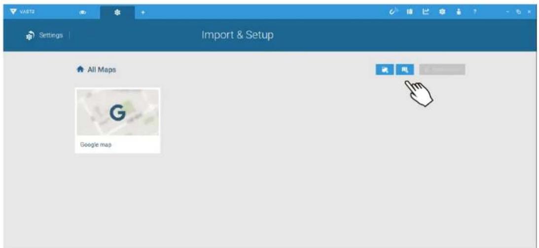
- An example of a bus is shown here. Double-click to edit the E-Map.
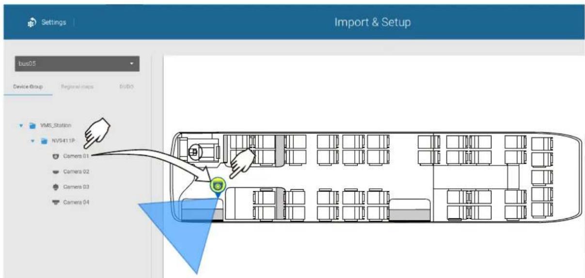
- Click and drag cameras to their corresponding positions on the vehicle.
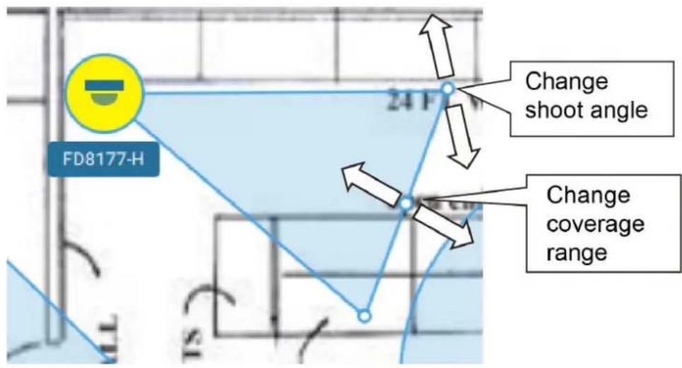
When the camera is in place, drag the FOV indicators on the edge to change the shoot angle and the coverage range.
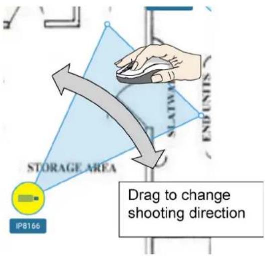
Drag the FOV to change the shooting direction to match the actual installation.
Click on the camera icon. You can also change the color of camera icon and the FOV type. Fisheye cameras, when ceiling mounted, have a round shape coverage.
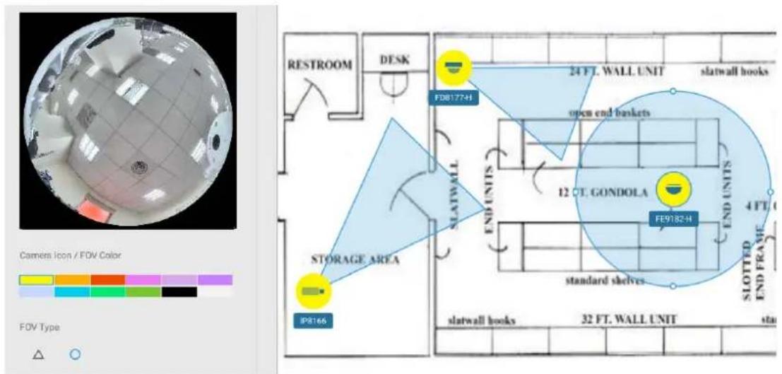
When your E-Map configuration is completed, click the Done button at the lower-right of the screen.
4. Double-Click the Google map icon.
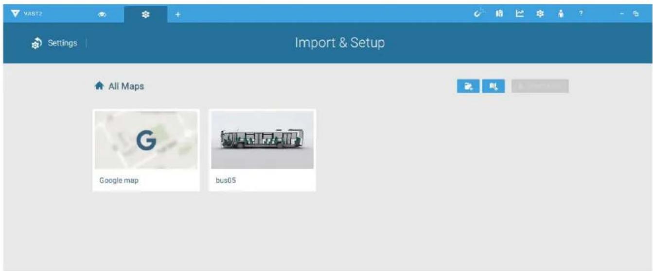
- The Google map window appears. Click on the GPS tab.
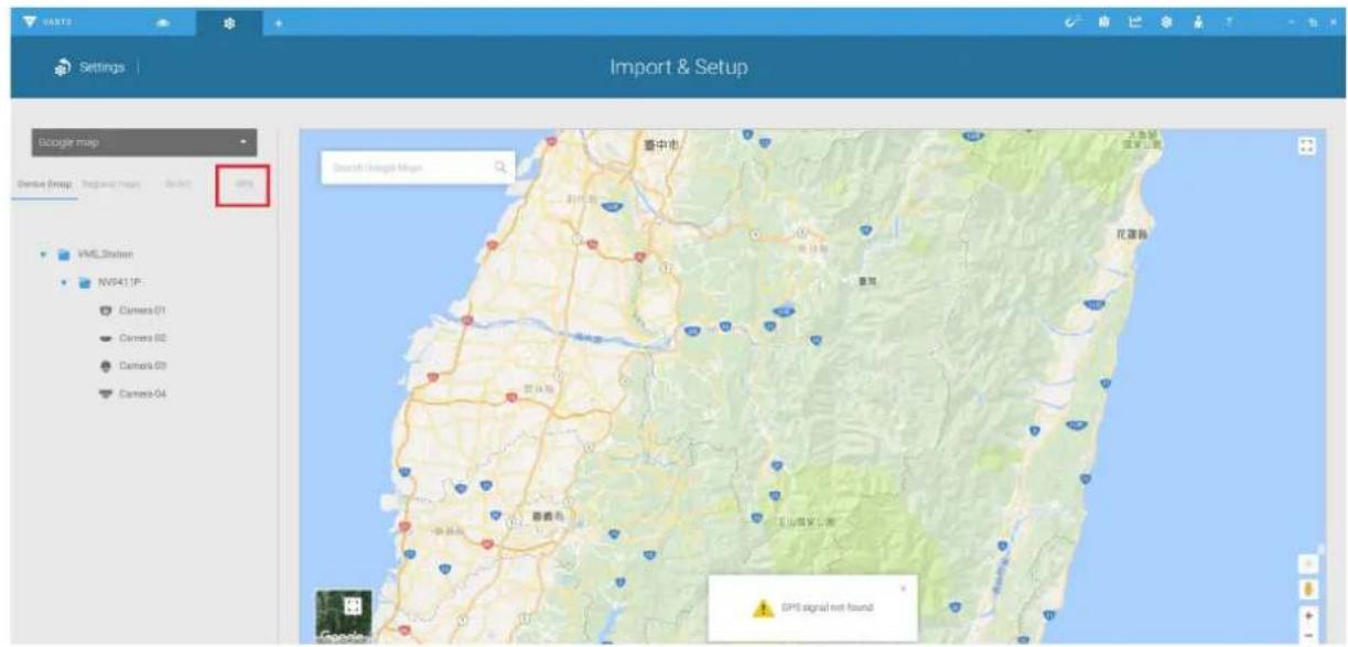
- Click the Add GPS button. The GPS device on the NVR will be listed.
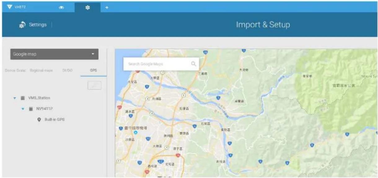
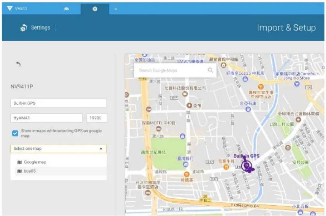
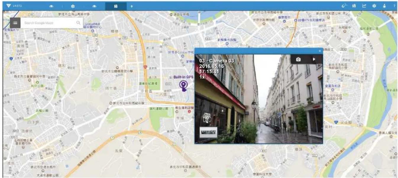
- Your GPS location should be found on the Google map. Double-click the Built-in GPS found under the NVR to display the current position.
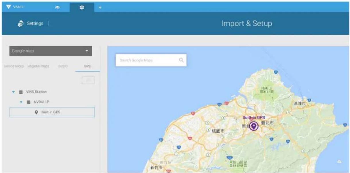
- Select the "Show e-maps while selecting GPS on google map" checkbox. Select the E-Map configured for your vehicle from the pull-down menu. Click the Apply button, and then click the Done button at the lower-right corner of the screen.
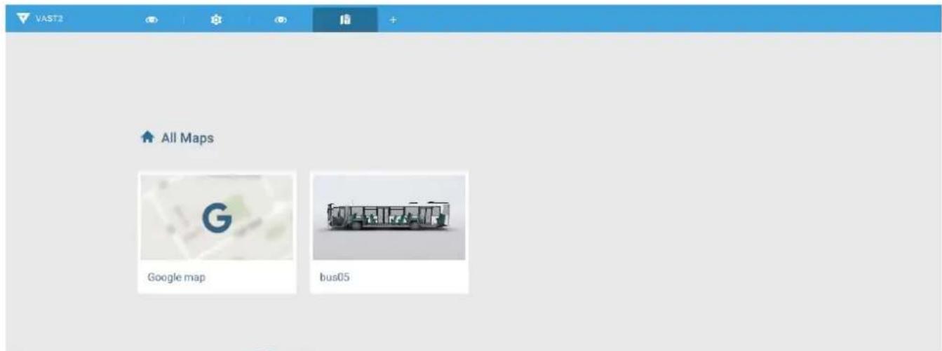
- Click to open the E-Map view. Double-click to open the Google map.
- A GPS location mark will appear on the E-Map showing the location of vehicle. Single-click on the location mark to display the associated vehicle's E-MAP.
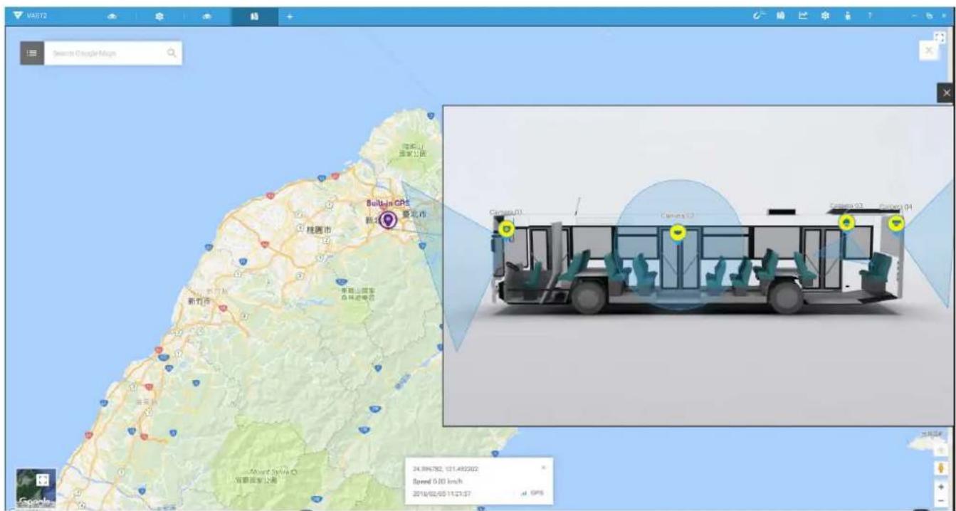
- You can click on any of the camera icons placed on the vehicle to display an instant live view. Note that one live view can display at a time.
Alarm
You can let a VAST server receive an event from NVR. The Alarms can be configured to perform a series of actions when different events occur. Alarms can be used to automatically react to possible threats. For example, the VAST server can start a recording or send an Email notification when Motion detection is triggered.
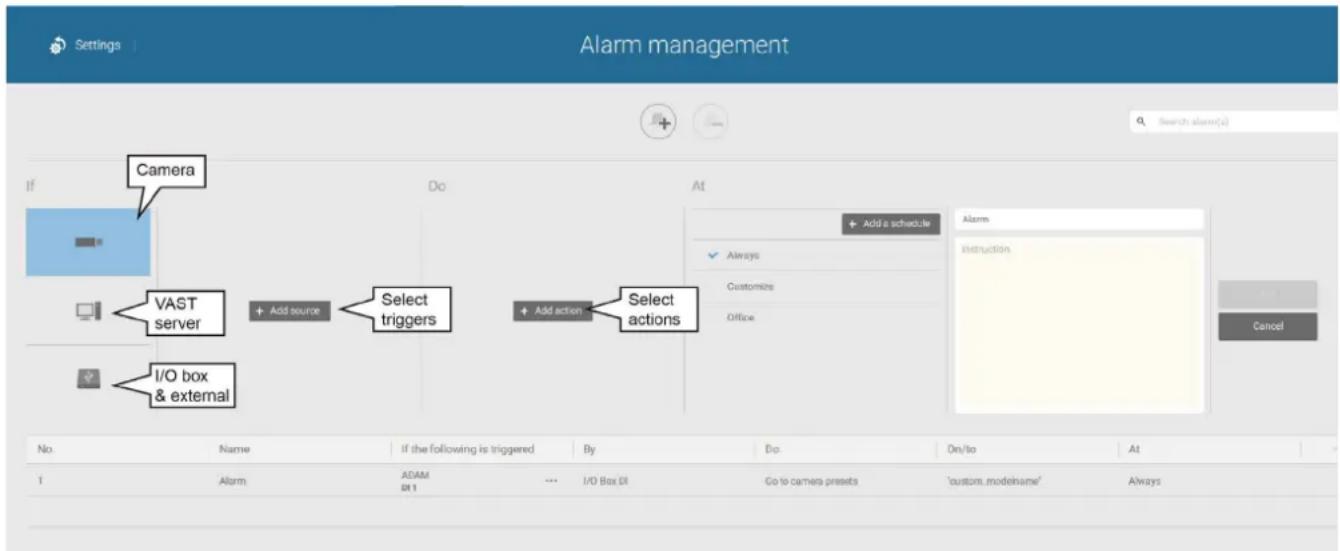
A wide variety of triggering conditions can be applied, including:
1. Camera triggers

| ● | Motion detection Field detection (VCA) | |
| ● | Camera DI Loitering (VCA) | ● |
| ● | Camera DO Camera disconnected | ● |
| ● | Tampering detection Recording error | |
| ● | Temperature Stop recording | ● |
| ● | IR (Infrared) Video loss (Video server only) | |
| ● | PIR (Passive infrared) | |
| ● | Line crossing (VCA) | |
Note that some of the triggers require that you open a web console to individual cameras. For example, Motion detection windows have to be manually configured on each camera before they can be configured in the Alarm settings.
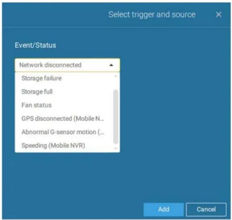
2. VAST server and NVR triggers

| ● | Network disconnection Th | these can be used to send maintenance notifications. |
| ● | Storage failure | |
| ● | Storage full | |
| ● | Fan status | |
| ● | GPS disconnected (Mobile NVR) | The GPS and G-sensor related options apply to the Mobile NVR that comes with the GPS and G-sensor. GPS can be used to track the speed and location of a vehicle, while the G-sensor can be used to detect abnormal impact or traffic accidents. |
| ● | Abnormal G-sensor motion (Mobile NVR) | |
| ● | Speeding (Mobile NVR) |
* Note that you should use the pull-down menu to select a triggering condition, and then click to select a mobile NVR.
The available actions include:
| ● | Start to record video Send HTTP requests |
| ● | Set DO status Send live streaming |
| ● | Go to camera presets Send email |
The Start to record video will record a video clip of the length of 10 seconds on the occurrence of an event.
The Set DO status will activate a DO connection. For example, to light an illuminator or sound an alarm.
The Send live streaming action will bring up a video prompt on the live view, showing the realtime video feed from a specific camera.
The Go to camera presets requires you to configure preset points on a PTZ camera before the Alarm configuration, such as a speed dome. Once triggered, the PTZ camera lens will move to a preset.
The VAST server automatically disables unavailable options. For example, when the DO option is selected, the cameras that do not support DO connections will be hidden.
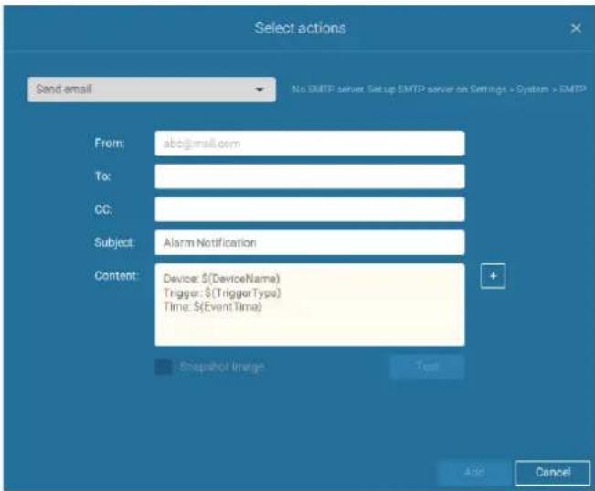
The Send email opens a configuration page where you should enter valid email addresses as sender and recipients. It is required that you configure an SMTP server for mail delivery in Settings > SMTP. Enter Subject and contents. Select the checkbox for including a snapshot of the event. When done, click Add to enable the action.
A reachable Mail server and Email accounts must be provided before you can apply the settings.
On the Schedule page, you can select to activate or de-activate alarm triggers throughout a specific timeline. For example, in some situations you can disable the alarm triggers during the office hours, and choose to enable the triggers only during the off-office hours.
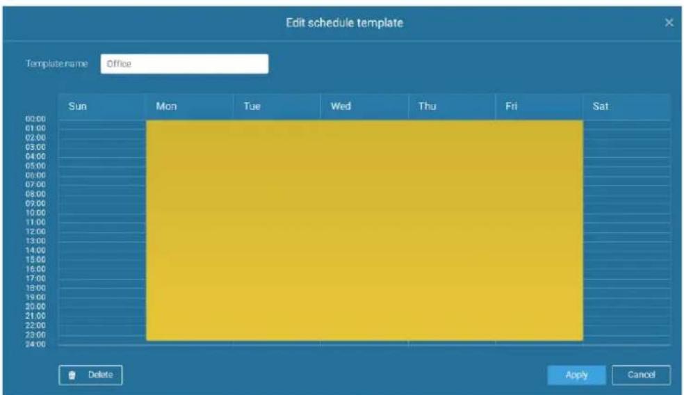
Click on any of the options on the Schedule panel for the alarm to take effet: Customize, Always, or Add a schedule.
You can manually create an effective time template using the New template button.
Save as a template...
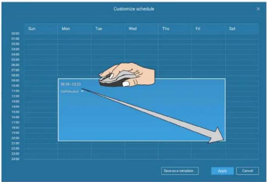
Click and hold down on the time cells, and drag the mouse to include the time span of your preference. The minimum selectable unit is half an hour. You can select multiple time spans on the template. Enter a name for the template, and click Add to save your template.
The same configuraion window apply to both the Schedule template and the customize schedule windows.
Make sure a Schedule mode is selected when you leave this configuration step.
Enter a name and instructions for users to follow, and then click Add to complete the Alarm setting.
All configured alarms will be listed on the Alarm settings page.
2-2-3. Playback Videos on the NVR H.D.D. from the VAST2 CMS Software
Since the NVR runs on Linux, you have to install the Ext2 File System Driver for Windows to access the recording files from a NVR hard disk.
The file system driver can be found here: https://sourceforge.net/projects/ext2fsd/?source=typ_redirect
Run and install the Ext2fsd-0.xx.exe. Follow the onscreen instructions to complete the installation.
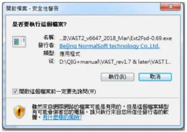
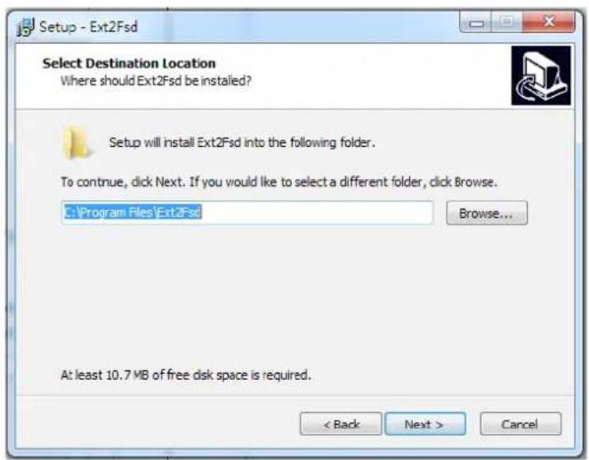
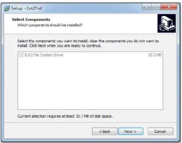
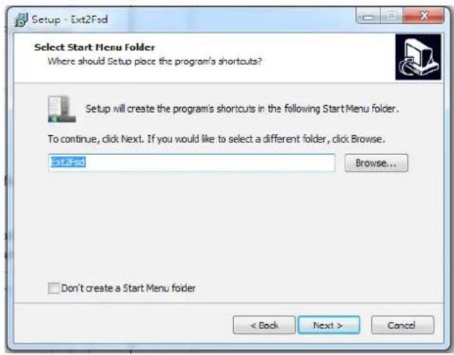
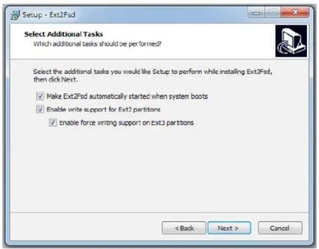
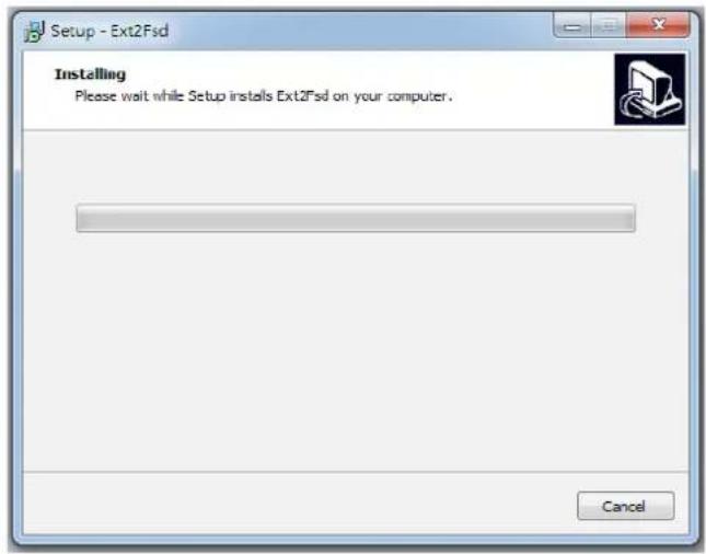
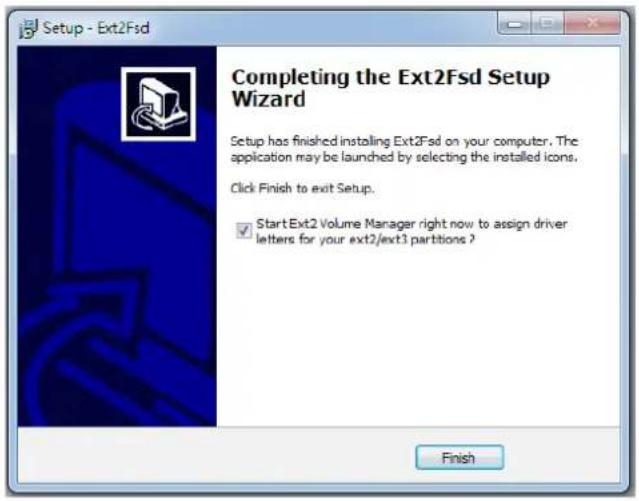
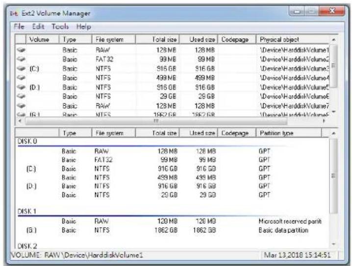
- Remove the disk tray box from a mobile NVR.
- Connect the disk tray box to your VAST server using a USB 3.0 type A to Micro B cable.
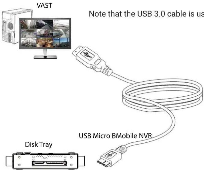
- From VAST, enter Settings > Device > Locabl DB.
-
There are 3 import types:
-
NVR disk: the drive tray box removed from a mobile NVR.
- NVR backup: the recorded videos exported from an NVR using a USB thumb disk or portable drive.
- VAST backup: scheduled backup from the local machine.
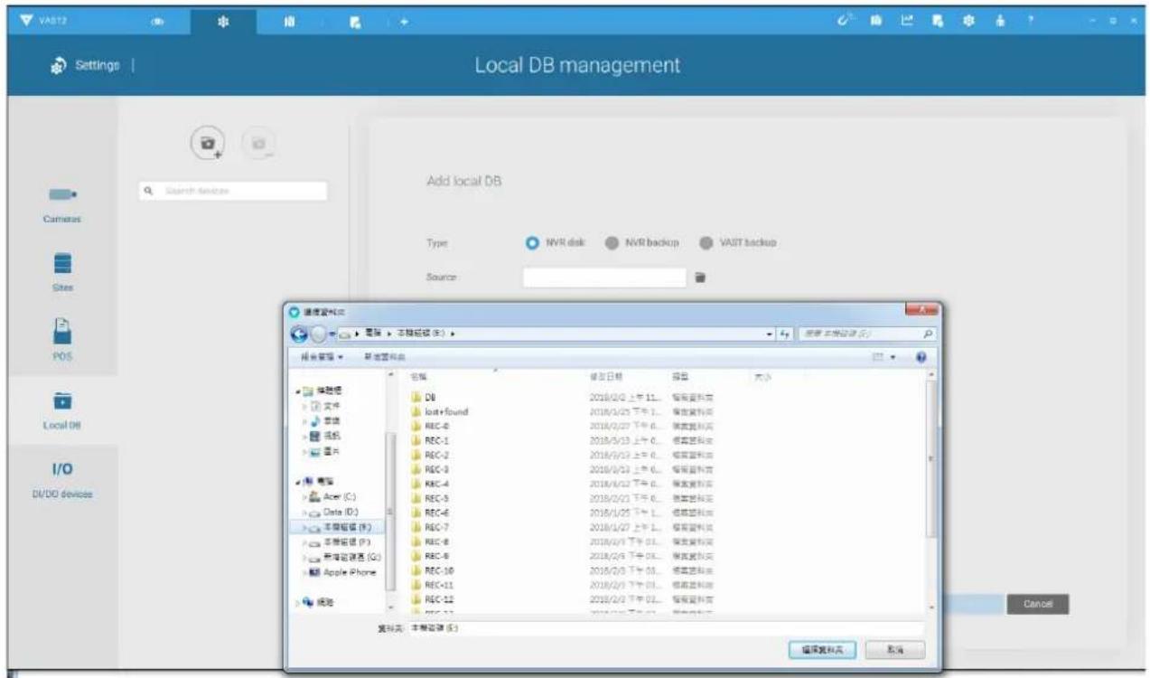
- Taking a mobile NVR's disk drive as an example, click the Source select button to locate the disk drive.
- The NVR will be mounted as a local DB.
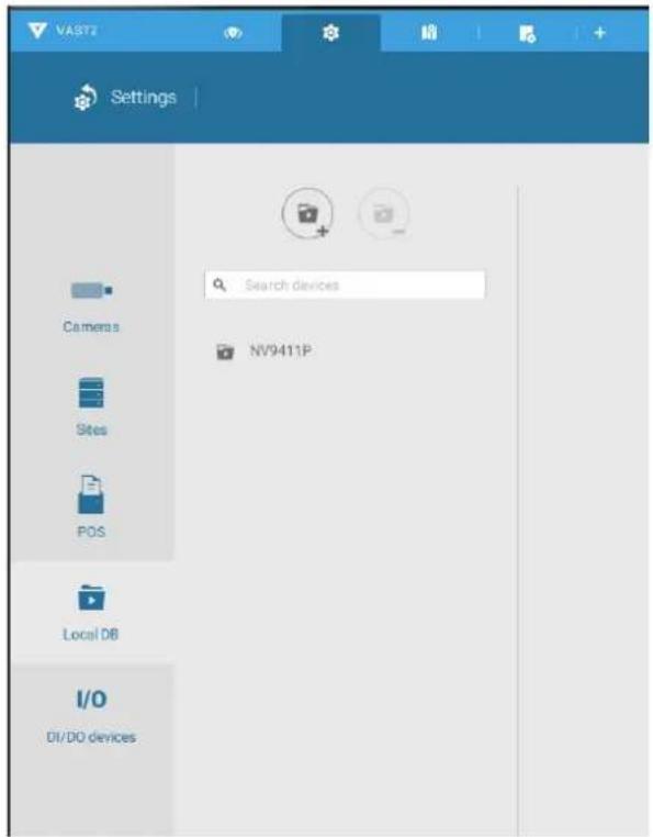
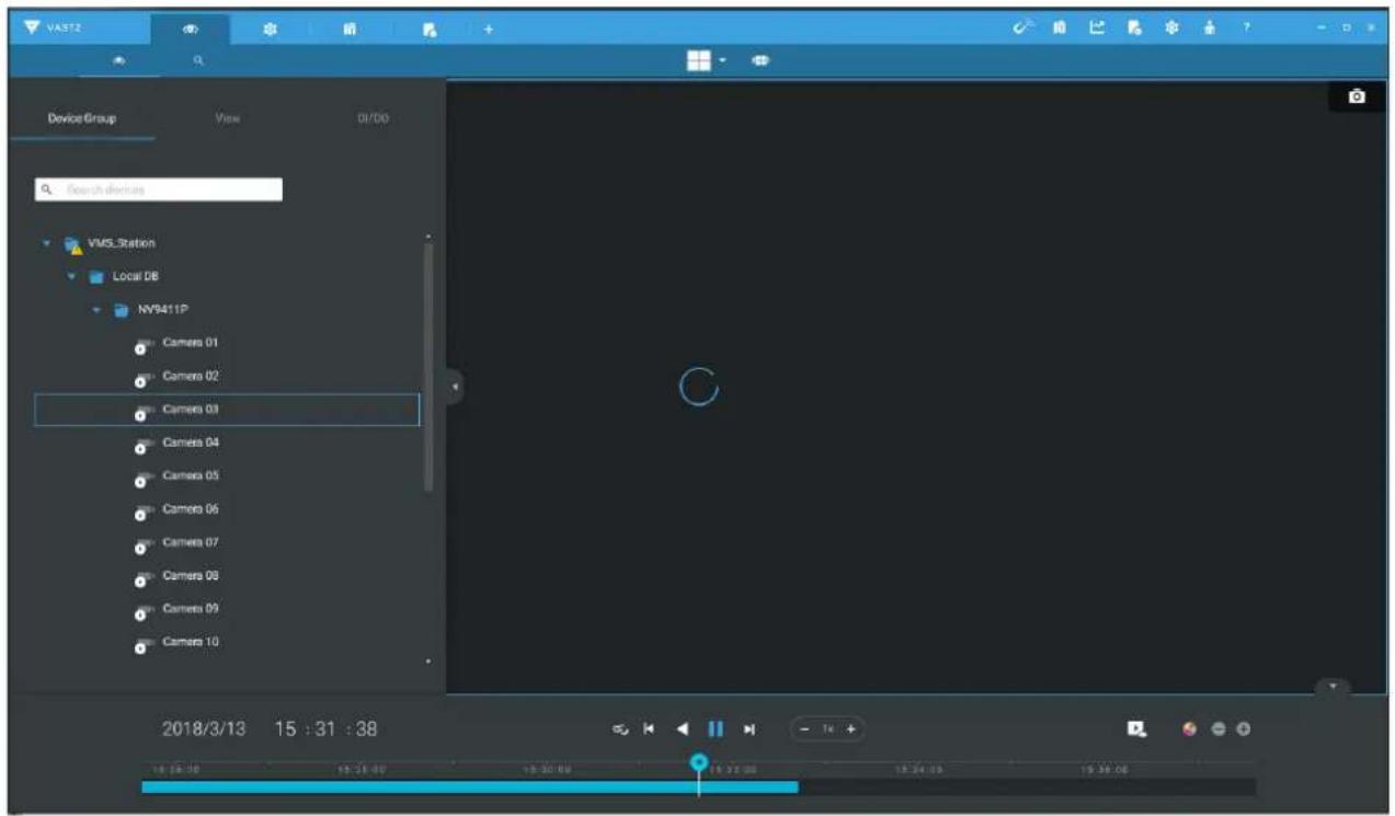
- A Local DB sub-tree will be listed under your server, and you can view the existing recordings on the NVR's disk drive.
2-3. Operation on Camera View Cell
2-3-1. PTZ Panel

Once you selected a camera, click on the PTZ button on a camera portal.
The PTZ panel will prompt. Below are the description of its functions:
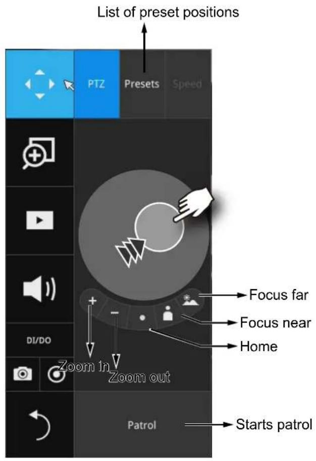
- PTZ control: Click and drag the nudget in the center towards the direction you wish to move to.
- Focus: Click on the Focus near and Focus far buttons to adjust camera focus.
- Home: Click to move the camera lens towards the default home position.
- Zoom: Use the Zoom in and Zoom out buttons to adjust the camera's zoom ratio.
- Presets: If you configured preset positions, a list of preset positions will appear.
- Patrol: If you configured preset positions into a patrolling tour, click on this button and the camera will proceed with patrolling through preset points.
Note that on a speed dome camera, the farther you pull the nudget away from the center, the faster the lens moves. This works like speed control.
Below is the PTZ panel that appears with ordinary PTZ cameras.
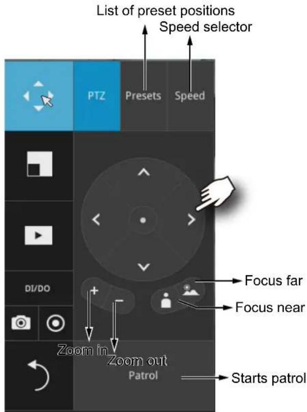
- PTZ control: Click on the arrow buttons to move towards the direction you wish to move to.
- Focus: Click on the Focus near and Focus far buttons to adjust camera focus.
- Zoom: Use the Zoom in and Zoom out buttons to adjust the camera's zoom ratio.
- Presets: If you configured preset positions, a list of preset positions will appear.
- Speed: Adjusts the speed when moving across the field of view.
- Patrol: If you configured preset positions into a patrolling tour, click on this button and the camera will proceed with patrolling through the preset points.

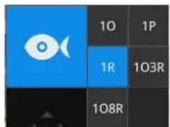
This portal appears with a fisheye camera. The PiP and PTZ buttons will then be disabled.
IMPORTANT:
Due to the limitation of system resources, the fisheye dewarp (1R & 1P) can only take place on one view cell, for one fisheye camera.
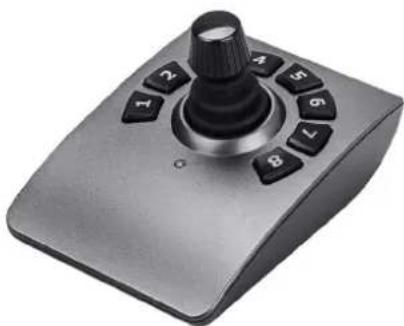
Joystick support
natural_image
Close-up of a metallic joystick controller with black buttons and a black handle (no visible text or symbols)The joystick related operations are listed below:
- Pan: Continuous move is supported. (joystick X-axis movement)
- Tilt: Continuous move is supported. (joystick Y-axis movement)
- Zoom: Continuous move is supported. To zoom in, move joystick Z-axis clockwise (or use button #2). To zoom out, move joystick Z-axis counter-clockwise (or use button #3)
- Home: joystick button #1.
- Auto Pan: joystick button #5.
- Patrol: joystick button #7. Preset positions must be pre-configured for the camera.
- Stop: Stops auto pan or patrol. Joystick button #6.
2-3-2. Digital zoom Panel

Digital zoom is a function that provides digital zoom into a live video. Be sure you place your mouse cursor inside the Global view window for the zoom function to take effect.
When activated, a Global view window will appear at the lower right of the view cell as shown below. You can display only a portion of the complete video frame as an area of your interest. Using a click and drag on the ROI window, you can instantly move to other areas within the video frame. Use the zoom ratio pull bar at the bottom to change the zoom ratio. You may also move the ROI around by click and drags.
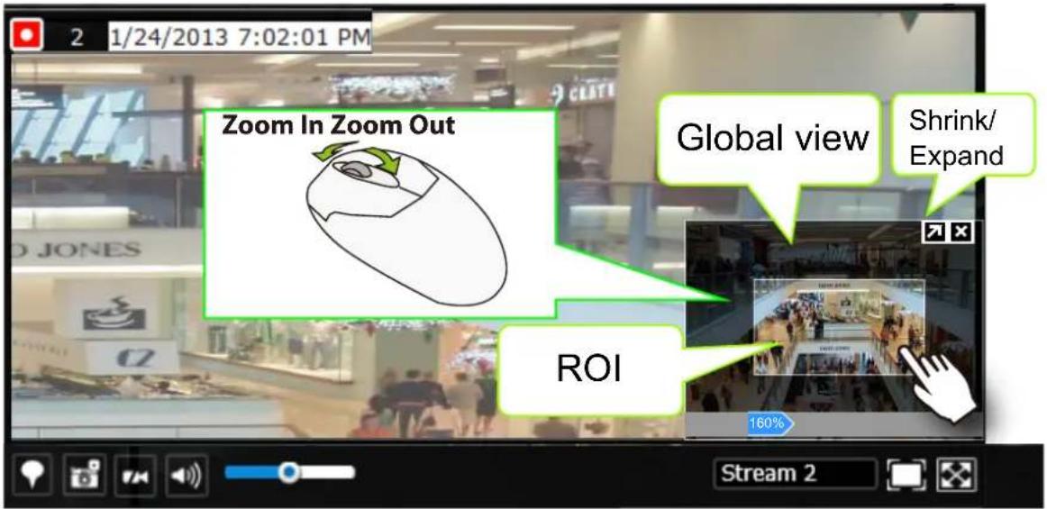
Note that not every camera supports the PiP function.

NOTE:
Please refer to page 163 for the description of fisheye display modes. The working theory on fisheye modes is identical for use on both local and web consoles. The fisheye mount type setting is found in the Settings window.
2-3-3. Play Recording Clips Panel

The Play Recording Clips function provides a shortcut to the latest recordings on the system. You can select 30 secs, 1 min, 3 mins, 10 mins, and 60 mins for an immediate playback.
For security reasons, using this function requires users to enter his/her credentials.
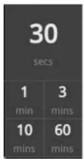
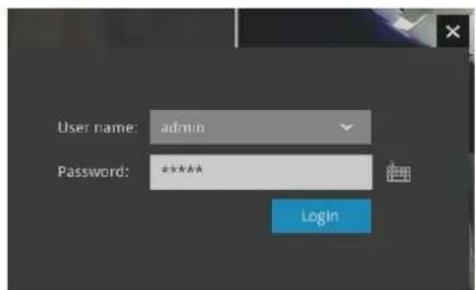
The Playback window will prompt, and a playback begins from the point in time you selected, e.g., 30 seconds ago. This function allows you to quickly review what has just happened.
2-3-4. DI/DO
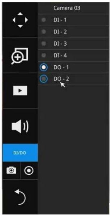
The DI/DO panel provides a glimpse of all DI and DO signal statuses from the connected cameras. You can manually trigger a digital output by clicking on its indicators.
When a digital input is triggered, its status will also be indicated on the panel.
Please note that DO is triggered by one click. You should then click again to disable the DO. Otherwise, the DO signal will be continuously triggered. As the result, if the DO is configured as an alarm trigger, many alarm messages will be generated.
2-3-5. Others
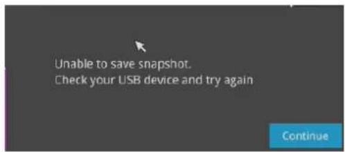
- Snapshot is used to take a snapshot from the camera currently selected. Note that this function only saves the snapshot (in JPEG) to a USB thumb drive.

IMPPORTANT:
The USB thumb drive has to be one that is formatted in FAT format.
- Manual Recording ☐: Press the button to start a manual recording from a selected camera. Click again to stop the recording.
- Return button : Click to return to the liveView window.

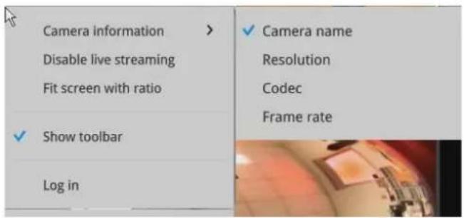
2-3-6. Right-click Commands
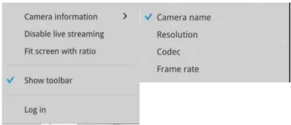
Left-click to select a camera. Right-click to display the selection menu.
- Camera information: Click to display camera name, resolution, codec, or frame rate on the view cell. The information will display on the upper left corner of a view cell.
- Disable live streaming: Select to display snapshots on screen instead of constantly streaming live videos.
- Fit screen with ratio: The NVR server automatically optimizes the display of camera view cells. However, you can still select this option to display the camera's original aspect ratio: for example, the original video feed can be 4:3. Without the fit screen, every camera's image will be expanded to fill the view cell.
- Show tool bar: You can hide the tool bars by deselecting this option.
- Log in/Log out: Log in to enable system configuration.
Chapter Three
Configuration Using the Local Console
The Main Control Portal
3-1. Layout
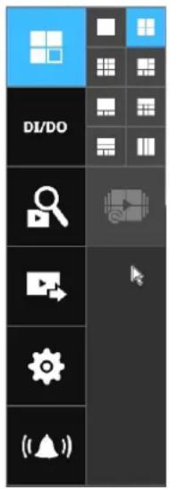
Move your mouse cursor across the screen to display the portal.
The first functional button is Layout. You can select the 1x1, 1x3, 2x2, 3x3, 1+5, 1+6, 2+3, 1+3, layout as the screen display. If you select the single view
layout, the rotation button will appear. Click the rotation button below to let the system swap the display of different cameras by every 10 seconds. The rotation speed is configurable via Settings > System > Display.
For NV9411P, the 1M+12 and 4x4 layouts are available.
3-2. DI/DO
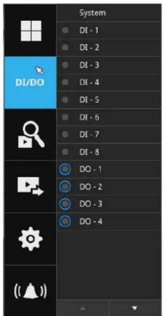
Click on the DI/DO button to display the full list of all DI and DO signals (whether they are connected or not) from all cameras in the configuration. If a digital input signal is triggered, e.g., the DI-4 on the left, its indicator will turn solid white.
3-3. Search recording clips
3-3-1. Time Search
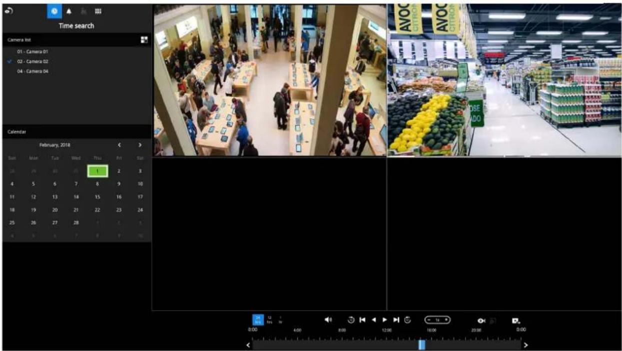
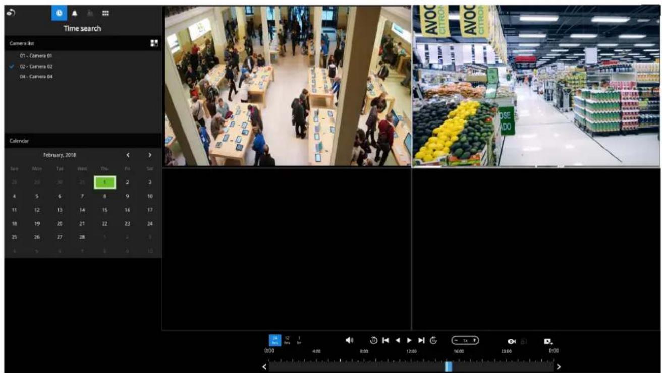
The search and calendar view will appear. Select a day on the calendar when the recordings took place (the days with recorded clips will be highlighted in blue and green). Single-click on a day to begin playback and search.
The date highlighted in green indicates today, and the green indicator does not necessarily mean that there are recorded videos today.
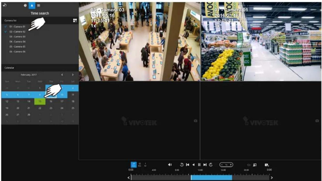
Use the layout button 📄 adjust view cell arrangement on screen. You can retrieve the recorded videos from a max. of 4 cameras at the same time.
Once you select to playback multiple cameras, the playback window will automatically turns into the 2x2 layout. Up to 4 cameras' recording can be played back simultaneously. This enables the synchronized playback of video produced by multiple cameras. Users do not need to switch from one camera to another when searching for forensic evidences.
The timeline bar enables quick skimming through the recording. Its functions are described as follows:
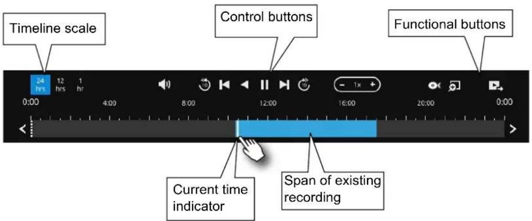
| Buttons Description | |
 | Time scale selector. Use the buttons to select the span of time displayed on the tool bar. |
 | Audio volume tuner. |
 | Plays back from 10 seconds ago. |
 | Previous frame. (I-frame only) |
 | Next frame. (I-frame only) After you paused a playback, use this button to browse video frame by frame. |
 | Play backwards. |
 | Play. This button is available after you paused a playback. |
 | Pause. |
 | Each click on it speeds down by 1/2. The slowest speed is 1/16. |
 | Each click on it speeds up by 2x. The fastest speed is 16 times. The current playback status is indicated on the screen. |
 | This button appears when you select to playback a fisheye camera's recording. This avails the selection of dewarp modes usable during the playback. |
 | Digital zoom. This applies when a camera is displaying the full of its field of view. You can use the Digital zoom function to zoom in on the field of view. |
 | Export clips. Use this function to select a span of time you want to export to other medias. |
By default, the playback starts from the beginning of a day's recording. While playing the recorded video, click on the timeline to replay a point in time in the video.

Snapshot. Takes a snapshot of the current FOV. The Snapshot button has been moved to the right-hand side of each view cell.
When playing the video recorded by a fisheye camera, the fisheye display options will be available on screen. You can click to select the 1O, 1P (Panoramic), 1R (Regional), 1O3R (1 Original and 3 Regional), or 1O8R modes. If 1P, 1R, 1O3R, or 1O8R mode is selected, you can exert the mouse control on screen, such as swiping the view, or hold down the mouse button and swipe the field of view.
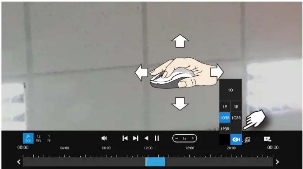
Please refer to the User Manuals that came with fisheye cameras, or page 163 for description of fisheye display modes.
Note that to export a video segment from the playback timeline,

- Click on the Export button
- Insert a USB drive formatted in the FAT format.
- Select the "From time" by clicking on the timeline. You can also manually enter the "From time" and the "To time."
- Click on the "From time" tab using a single click.
- Repeat steps 3 and 4 to configure the To time.
- Click on the Export button.

The export process is indicated on the right. Depending on the length of footage to be exported, this process can take minutes.

When completed, a message will display on screen.
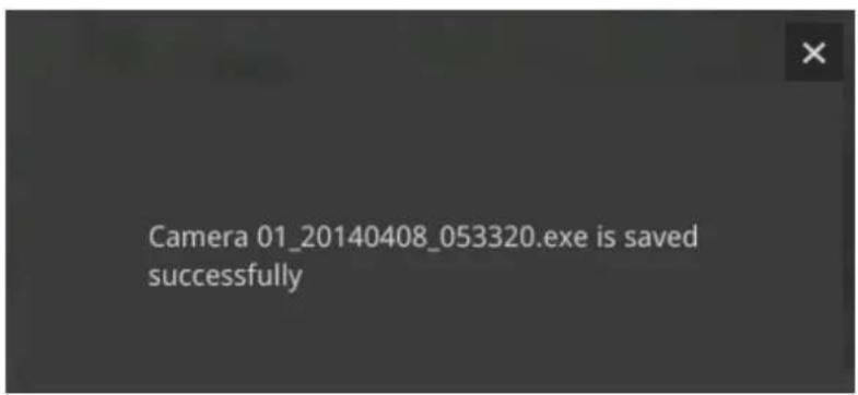
The default for export is 5 minutes before and 5 minutes after the point in time that is currently selected.
3-3-2. Alarm Search
Click on the Alarm search button on the upper left of the screen to enter the Alarm Search panel.
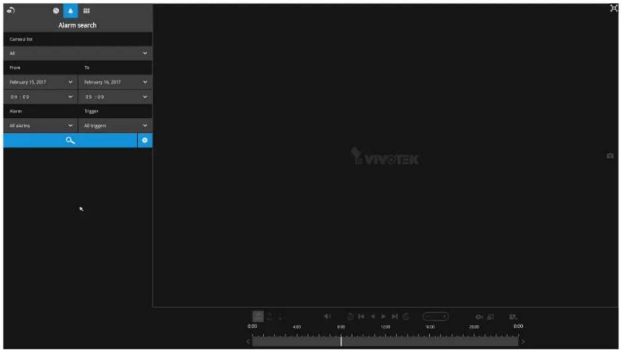
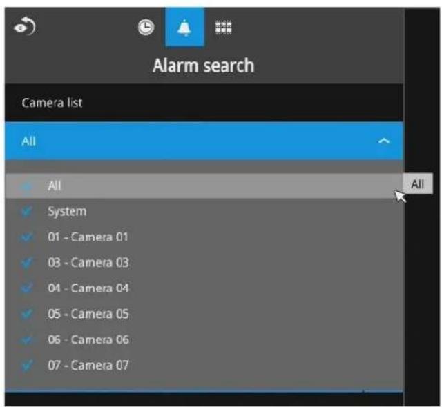
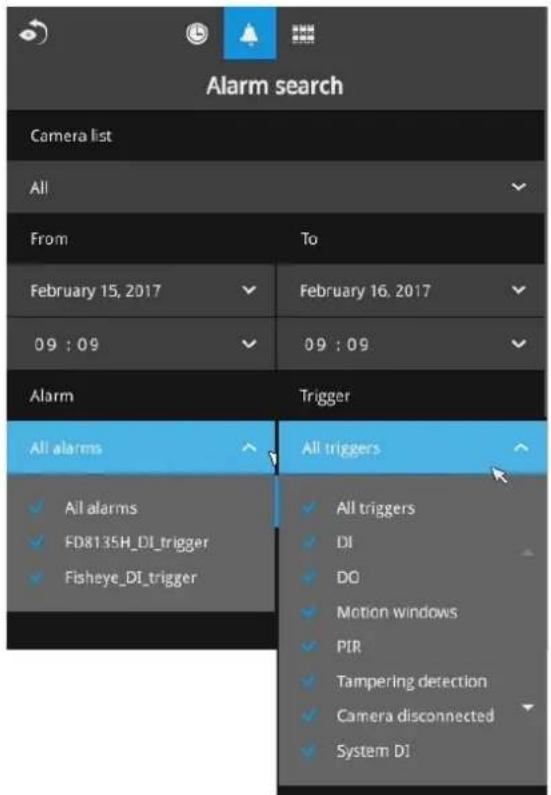
You can specify the search criteria by selecting the devices to be involved in the Alarm search. The default is All.
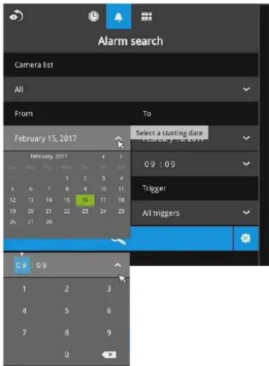
You can then specify the start time and end time to configure a span of time to be searched. Click to expand the calendar view and keypad to specify the From and the To time to cover the possible time of occurrences.
You can also determine what types of alarms will be included in the search. Select the pre-configured Alarms or select the Trigger types from the pull-down menus.
When done with the selection, click on the Search button. In the sample screen below, a list of alarms is displayed, and you can click on any of them to replay the moment when the alarm was triggered. The alarm-related recording will typically include a length of 5 seconds of pre-alarm and 20 seconds of post-alarm footage.
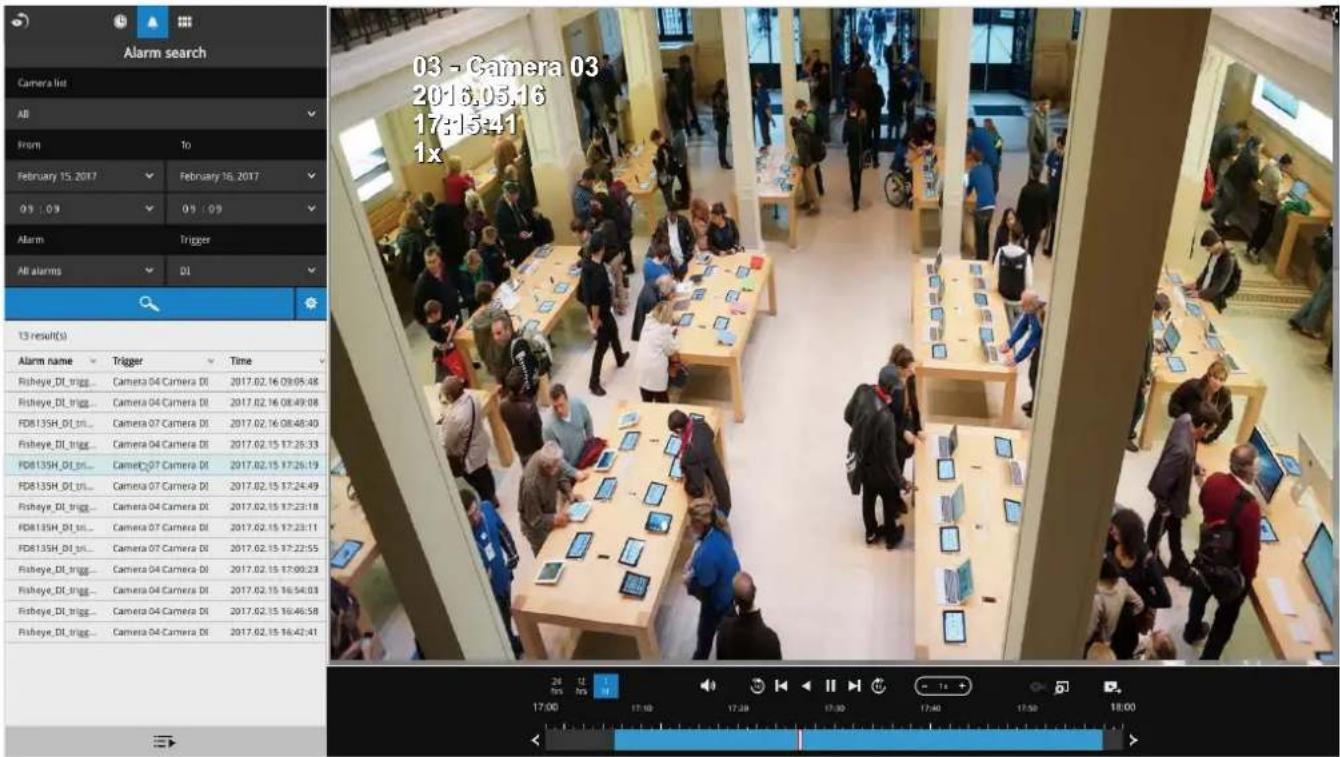
Up to 200 search result entries will appear. If more than 200 entries have been found, click on the New results button on the last entry page.
If two cameras participate in the recording of an alarm-related event, the footage of one camera will be played first, and then that of the other.
If user's operation takes place (pause, rewind, etc.) during the playback, the system will stop the consecutive playback of multiple alarm footages.

NOTE:
When the Search window is left unattended for 10 minutes, the NVR will return to the live view display. To enter the Search window, you will have to enter the user credentials again.
3-3-3. Storyboard
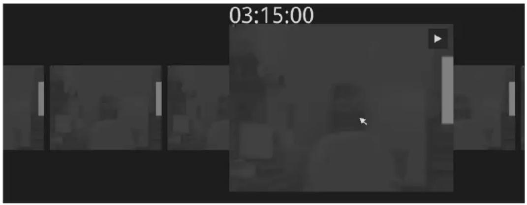
The Storyboard interface provides a glimpse of past recordings over a timeline. It looks like doing the film editing after a film was shot.
To enter the Storyboard window, click on the Storyboard shortcut on the upper-left of screen. Below are the screen elements of the Storyboard window:
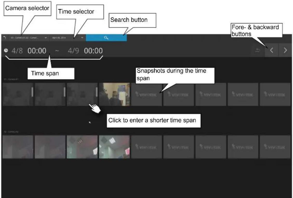
To search for a particular video footage, select the target cameras and the time of recording. On the Storyboard, the timelines of up to two cameras can be displayed.

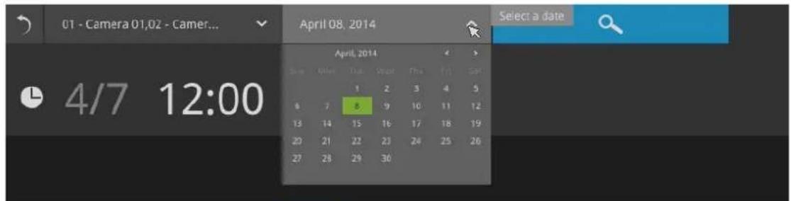
Click on the Search button
Mouse over the line of snapshots to display its time of recording. Click on a snapshot of your interest. The time of recording is immediately displayed on top of it.
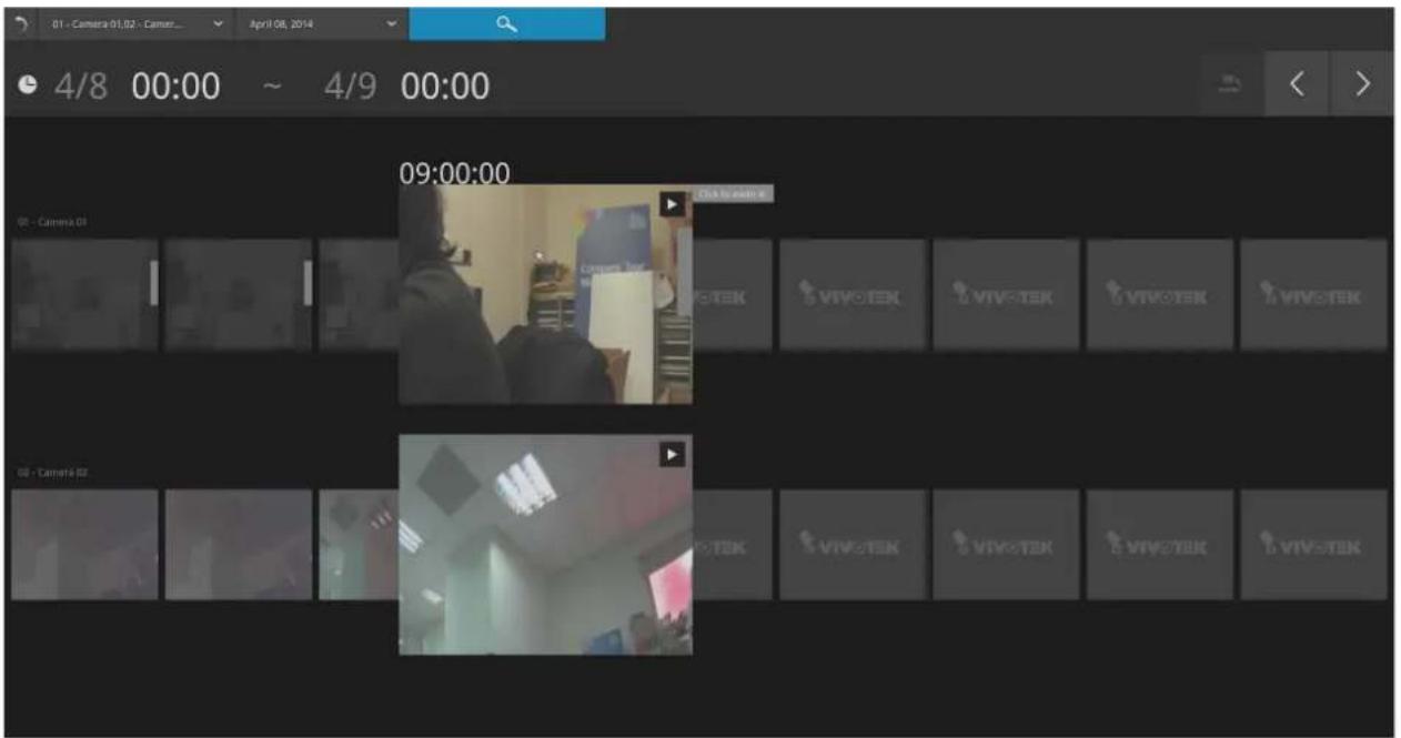
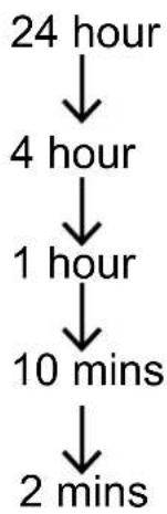
The detailed search is based on a narrow-down criteria. The search begins from a 24-hour time span, and then moving in to a 4-hour, 1-hour, 10-minutes, and 2-minutes span. When the screen displays a 24-hour span, each snapshot represents a 3-hour time span.
Each click on a snapshot brings you deeper into the timeline.
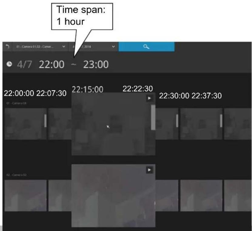
Below is a sample screen showing the screen of a one-hour time span. Each snapshot represents a point in time 7.5 minutes apart. Click on a snapshot of your interest to get deeper into the timeline.
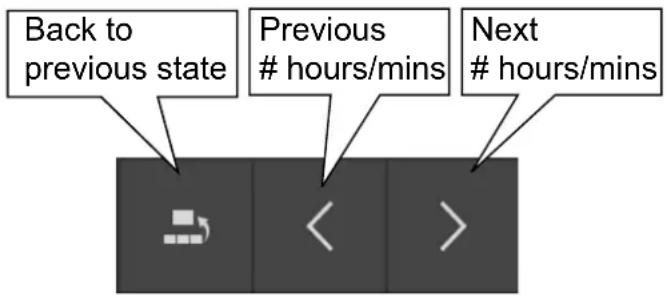
If you find yourself in the wrong segment on the timeline, use the buttons on the upper-right of the screen to travel.
The definitions of these buttons depend on the time span of your current position. For example, if you are in a 4-hour time span, the "Back to previous state button" will bring you back to the 24-hour time span.
The smallest time span is 2 minutes. And on the screen of 2-mins span, each snapshot represents a 15 seconds video footage.
You can then click on the Play button ▶ to playback the recorded footage.
The playback window will appear. Please refer to page 75 for the operation details.
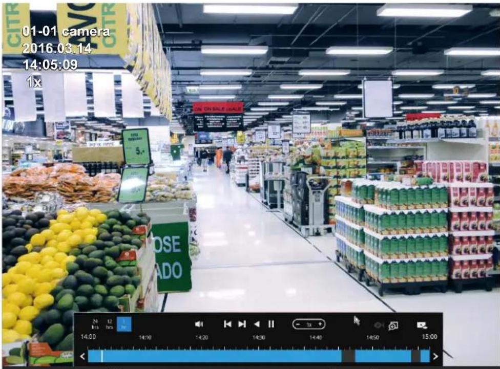
To return to the Live View window, click on the Back to Search recording clips button and the Back to Liveview button on the upper-left of the screen.
3-4. Export recordings

The Export recordings button allows users to directly select a piece of recordings by a specific camera, and export that to a USB thumb drive. Users can select one or multiple cameras, select a period of time in which the recording took place, and then click export.
The max. length of recording export is 24 hours.
To export recordings:
- Attach a USB thumb drive formatted in FAT format to the NVR's USB port.
- Select one or multiple cameras from the list.
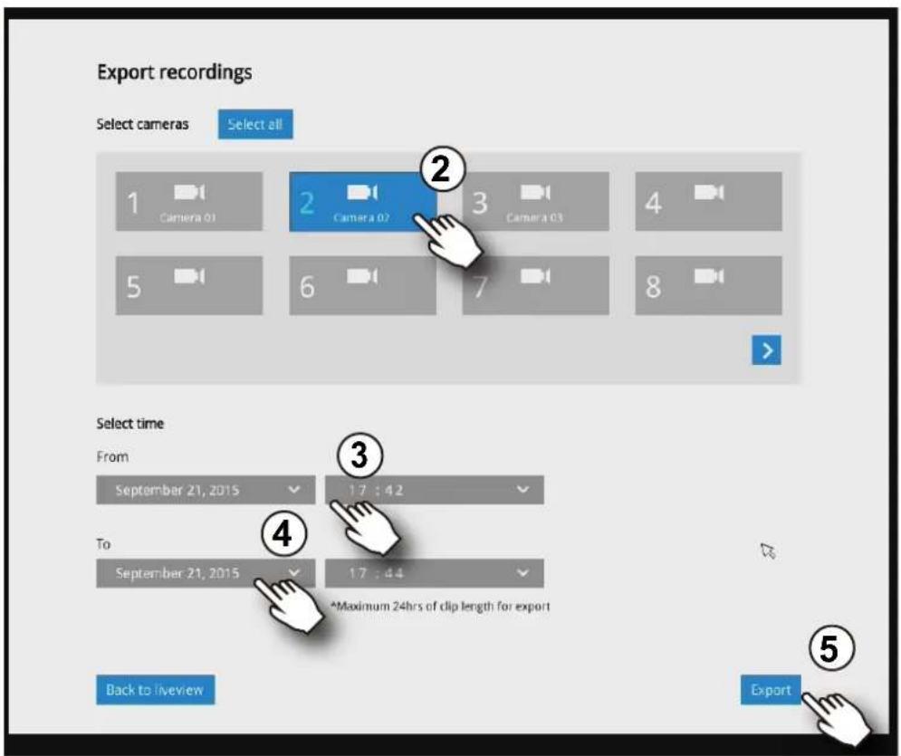
- Select the start time of the period of recording time.
- Select the end time of the period of recoding time.
-
Click the Export button.
-
The Export progress will be shown.
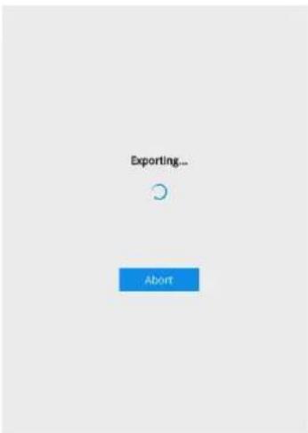
- When the Export process is done, select to resume another export or go back to the live view.
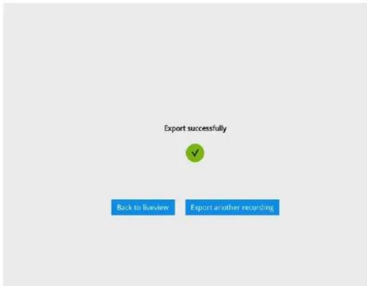
Note that the Export process can take a long time if the time span of the selected video is very long.
3-5. Settings
3-5-1. Settings—Overview

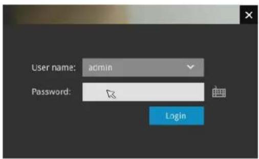
Click the Settings button to start the camera and system settings window. A confirm box will prompt. Enter User name and Password to proceed.
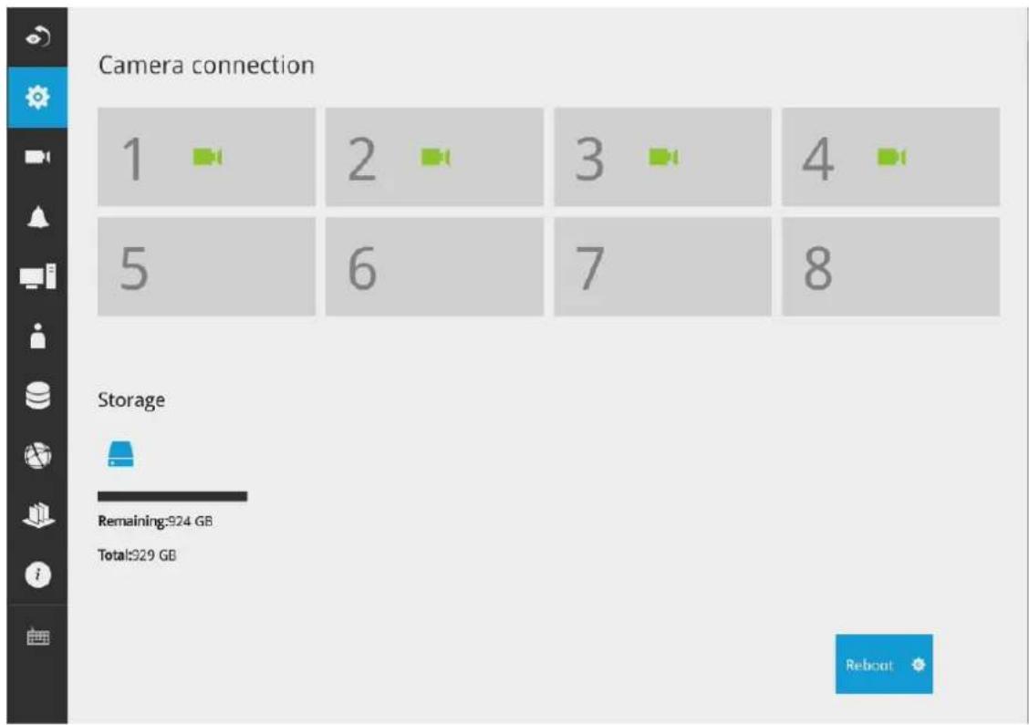
The system will default to the overview page displaying the camera connection and storage statuses. An empty position will be left in blank, and a disconnected camera will be indicated as 📄. The storage volume usage is displayed as the used and unused spaces.
The Reboot button is also available on this page. There are critical conditions that can sound the system buzzer, such as a disk failure.
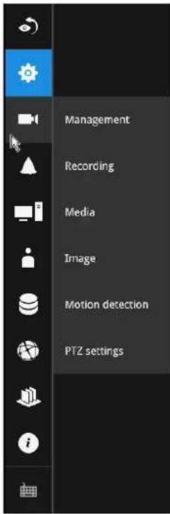
The Camera menu provides access to Management, Recording, Media, Image, Motion detection, and PTZ settings pages.
3-5-2. Settings-Camera-Management
On the camera Management page, you can configure the following:
- Recruit or disband cameras.
- Create a camera name.
- Assign User name and Password, or apply the credentials to all cameras in your configuration.
- Change the Network settings.
- Change the cameras' positions on the layout screen.
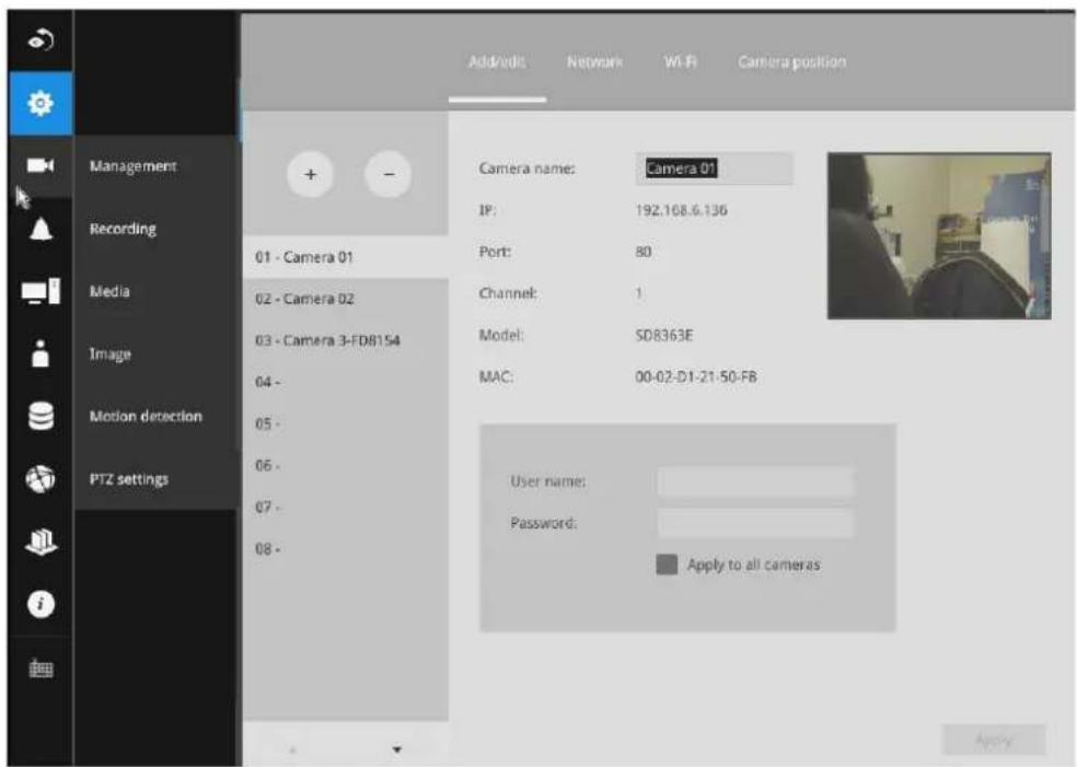
For a camera name, you can enter up to 64 alphabetic and numeric characters including [0-9][a-z][A-Z][_][-]\. For user name and password, you can enter up to 64 alphabetic and numeric characters including [0-9][a-z][A-Z][!][\][%][-].[.][@][''][\~].
To recruit cameras:
- Click on the Add button. A list of cameras in the same subnet will appear.
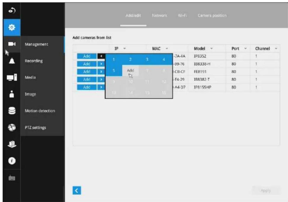
- Click the Add button, the camera will be placed at an unoccupied position. You may also expand the menu on the side of the Add button to select a position number.
- When a camera is added, it should appear on the graphical placement below.
- Click the Apply button after you added cameras.
- You may click the page back button < to return to the previous window.
To disband cameras:
- Click on the Remove button. A list of cameras will appear.
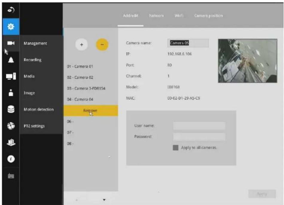
- The Remove button will turn yellow 🔍. Mouse over to the camera you want to remove, and its entry will display the Remove message.
- Click on the Remove message. The camera should then disappear from the camera list. The recording from that camera will also be discontinued.
Network
On the Network tabbed window, you can configure the network type, IP address, and the connection ports for video streaming.
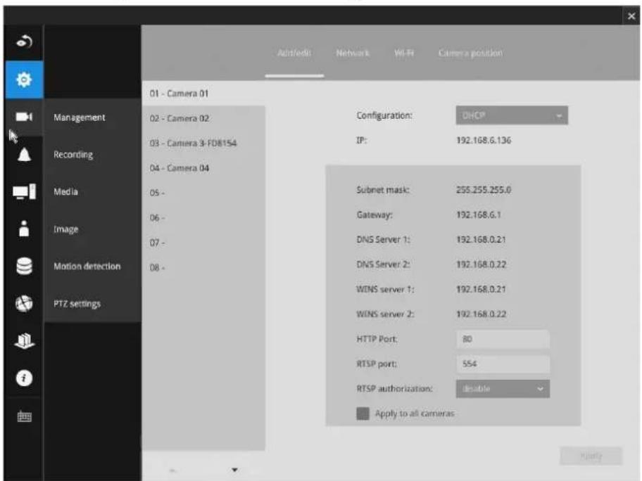
You can select DHCP as the method for cameras to acquire IP addresses, or you can manually configure static IPs for a single or all cameras. Using static IPs is recommended. Although the NVR can remember the MAC addresses of cameras, if IPs are changed under the DHCP configuration, your NVR may still fail to connect the cameras. Please consult your network administrator for details about network settings. It is usually not necessary to change port numbers for the HTTP and RTSP ports unless there is a conflict in your network environment.
Wi-Fi
If wireless cameras are recruited by the NVR, its wireless connection details are shown in here.
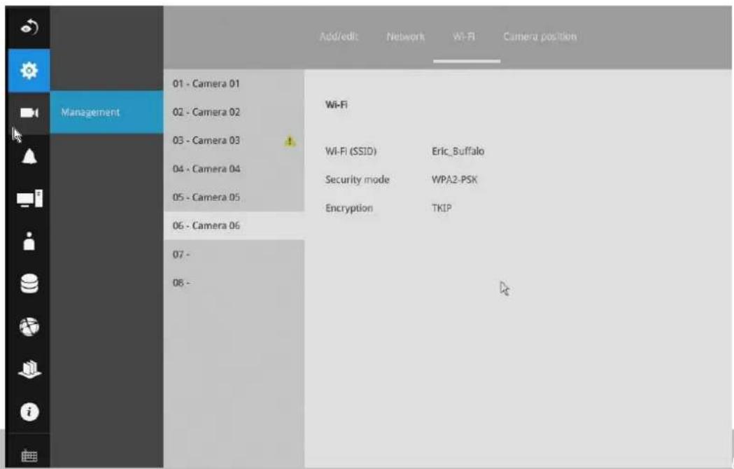
- Wi-Fi (SSID): Displays the AP (Access Point) this camera is connected to.
- Security mode: Displays the security mode used for the security encryption.
- Encryption: Displays the encryption standard currently applied.
Camera position
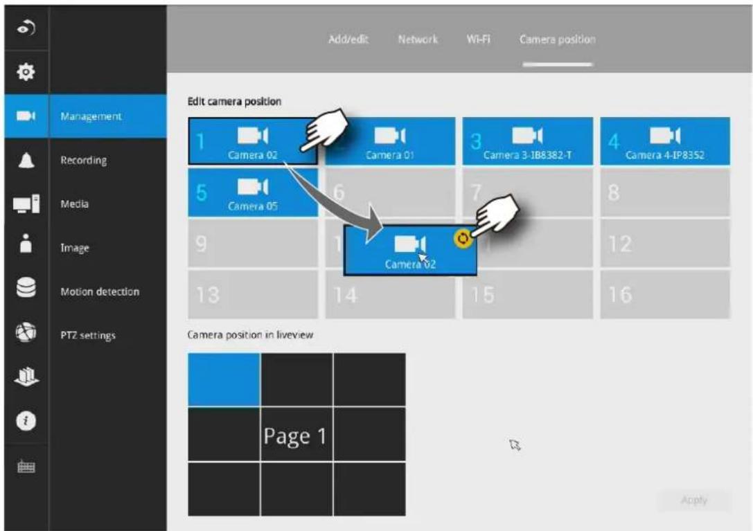
To change a camera's position on the Liveview layout, click and drag a camera to an unpopulated position. Note that you cannot swap the positions of two cameras by dragging a camera onto a position already populated by the other. Also, the camera index number on the management list is not affected by the change of positions. Click the Apply button for the configuration change to take effect. The position screen displays the current layout on the Liveview screen.
3-5-3. Settings-Camera-Recording
Recording options
On the camera Recording page, you can configure the following:
- Configure the duration of camera events, for the concern that camera can be too frequently triggered.
- Enter the Pre- and Post-event recording time. The triggering events can be DI, DO, Motion detection, PIR, or Tampering detection.
- The default recording stream is Stream 1, and the system automatically adjusts the frame rate, resolution, etc. for optimum performance. However, you can still change the streaming characteristics. Note that you can not assign the recording task to other video stream.
- Watermark password: Configure a password in a length of 16 to 64 characters. You can use it to verify the authenticity of exported videos using the included video player.
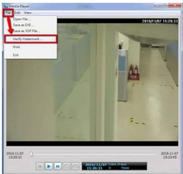
Select File > Verify Watermark.
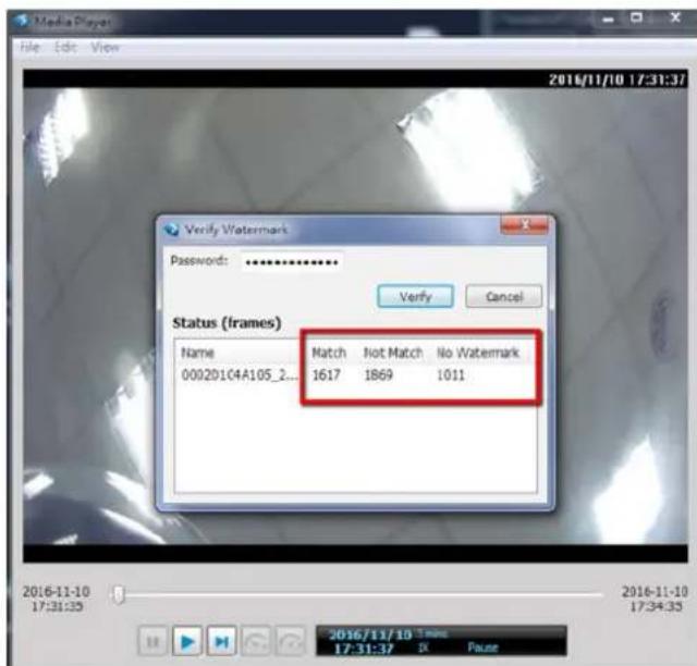
Enter the password to verify. If the Not match value is 0, the video is the original and has not been tampered with.
3-5-4. Settings-Camera-Recording
Recording options
On the camera Recording page, you can configure the following:
- Configure the duration of camera events, for the concern that camera can be too frequently triggered.
-
Enter the Pre- and Post-event recording time. The triggering events can be DI, DO, Motion detection, PIR, or Tampering detection. A recording length of 10 seconds of pre-event and up to 300 seconds of post-event can be configured.
-
The default recording stream is Stream 1, and the system automatically adjusts the frame rate, resolution, etc. for optimum performance. However, you can still change the streaming characteristics. Note that you can not assign the recording task to other video stream.
-
Enable the Activity Adaptive Streaming feature. This feature records the I-frames only when there are no activities detected. When activities or alarm are triggered, the camera raises the recording stream to the full frame rate. This feature can save tremendous amount of bandwidth.
-
Enable or disable audio recording. Note that audio transmission through HDMI cable is currently not available.
-
Change the life expectancy of the recording data.
-
You can apply a typical configuration to all cameras using the Apply to all cameras checkbox.
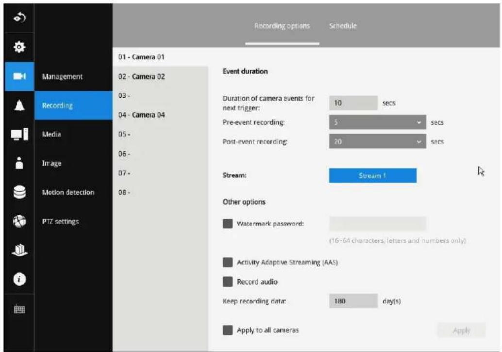
You can refer to the User Manuals that come with your network cameras for more discussions of these configurable options.
Recording Schedule
By default, all video feeds from cameras are recorded at all time. You can modify the recording task using the schedule tool:
-
Click to select a recording condition's checkbox-1. Continuous recording, Event recording
, and 3. Clear (no recording). -
Click and drag on the cells on the time table. For example, to stop the recording during a period of time, select the Clear checkbox and move the cursor across the time table. The minimum unit on the table is half an hour.
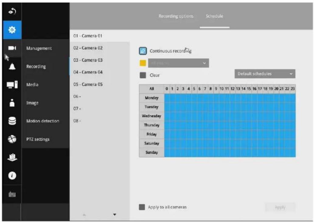
-
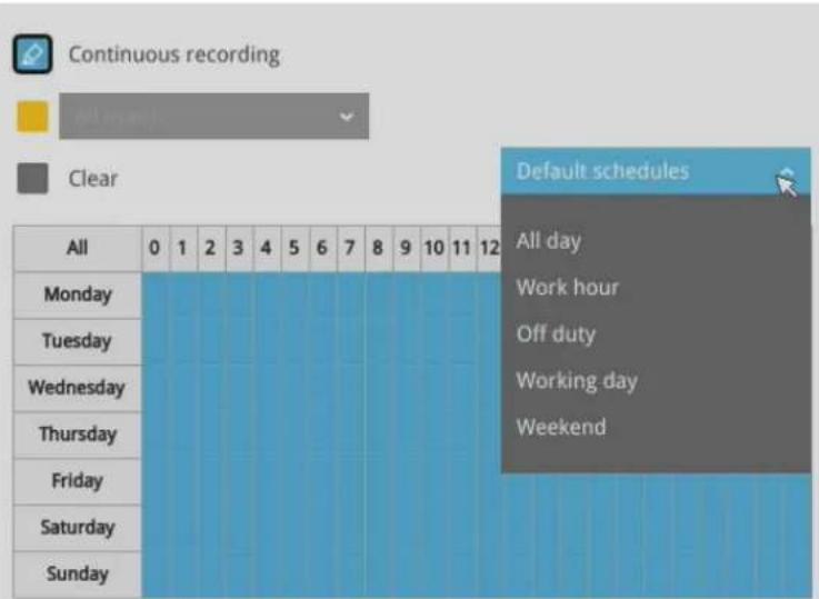
You may also use the scheduler tool on the right to facilitate the process. You can select a condition checkbox, and then select the All day, Work hour, Off duty, Working day, Weekend options to apply a time selection.
-
Repeat the process on individual cameras or select the Apply to all checkbox if the schedule can apply to all cameras.
-
When done with the configuration, click on the Apply button.
Note that Event-triggered recording and continuous recording can not be taking place at the same time.
3-5-5. Settings-Camera-Media
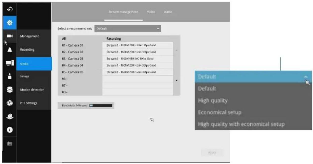
Stream management
The stream here refers to the recording stream, namely, Stream 1. You can use these preset conditions to configure the resolution, image quality, frame rate, and the bandwidth consumption of the recording stream on this window.
| Recommended setting | Configuration |
| Default Medium resolution | full frame rate |
| High Quality Guaranteed video quality set as Good; full frame rate | |
| Economical Medium to low resolution; frame rate at 5fps | |
| High quality w/economical | High resolution, Good image quality; frame rate at 5fps |
With each recommended configuration applied, the estimated bandwidth consumption value is immediately calculated and displayed at the lower screen.
Click the Apply button for the configuration change to take effect.
Video
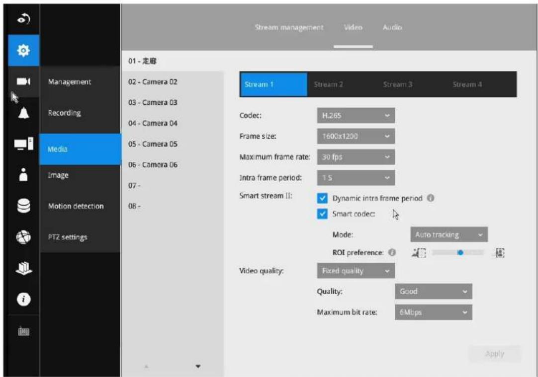
The Video window allows you to configure all video streams (the no. of stream available can be different for different models). You can configure the following:
- Codec: video compression codec in H.264, MPEG-4, or MJPEG. Note that MPEG-4 is not supported for Liveview.
- Frame size: video resolution. Note that due to the limited CPU resources, you may not be able to change the resolution to a very high value, e.g., 5MP in the 1920x1920 resolution.
- Maximum frame rate: the highest frame rate.
- Intra frame period: How often an I-frame will be inserted into the video stream.
- Smart Stream II: Some newer camera models come with Smart Stream features. Please refer to the next page for detailed information.
- Video quality: You may either select Constant bit rate or Fixed Quality as the defining rules for video transmission;
| Constant bit rate Places a packet size threshold on video frames; This guarantees the frame rate per second performance, yet image quality can be compromised if bandwidth is not sufficient in your network environment. |
| Fixed Quality Guaranteed video quality, and to ensure image quality, some frames may be dropped when bandwidth is not sufficient. |
When done with the configuration, click the Apply button.
■ Dynamic Intra frame period
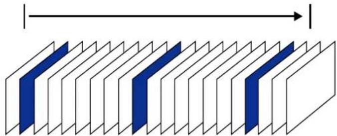
High quality motion codecs, such as H.265, utilize the redundancies between video frames to deliver video streams at a balance of quality and bit rate.
The encoding parameters are summarized and illustrated below. The I-frames are completely self-referential and they are largest in size. The P-frames are predicted frames. The encoder refers to the previous I- or P-frames for redundant image information.

natural_image
Abstract geometric pattern with alternating blue and white parallelograms (no text or symbols)PIPPPPPPPIPPPPPPPI
H.264/265 Frame Types
By dynamically prolonging the intervals for I-frames insertion to up to 10 seconds, the bit rates required for streaming a video can be tremendously reduced. When streaming a video of a static scene, the Dynamic Intra frame feature can save up to 53% of bandwidth. The amount of bandwidth thus saved is also determined by the activities in the field of view. If activities occur in the scene, firmware automatically shortens the I-frame insertion intervals in order to maintain image quality. In the low light or night conditions, the sizes of P-frames tend to be enlarged due to the noises, and hence the bandwidth saving effect is also reduced.
Streaming a typical 2MP scene normally requires 3\~4Mb/s of bandwidth. With the Dynamic Intra frame function, the bandwidth for streaming a medium-traffic scene can be reduced to 2\~3Mb/s, and during the no-traffic period of time, down to 500kb/s.

natural_image
Abstract geometric pattern with alternating blue and white parallelograms (no text or symbols)PIPPPPPPPPPPPPPPPPPPI
Static scene
Dynamic Intra Frame w/ static scenes
natural_image
Diagram of layered structures with blue and white sections, no text or symbols presentPIPPPPPPPIPPPPPPPI

Activities
Dynamic Intra Frame w/ activities in scenes

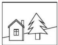
■ Smart codec effectively reduces the quality of the whole or the non-interested areas on a screen and therefore reduces the bandwidth consumed.
You can manually specify the video quality for the foreground and the background areas.
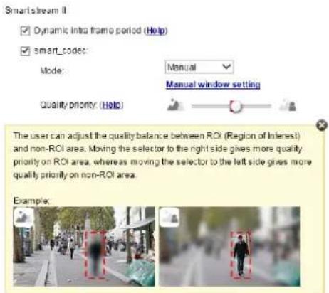
Slide bar to the right–higher quality in the ROI areas Slide bar to the left–higher quality in the non-ROI areas.
Select an operation mode if Smart codec is preferred.
- Auto tracking: The Auto mode configures the whole screen into the non-interested area. The video quality of part of the screen returns to normal when one or more objects move in that area. The remainder of the screen where there are no moving objects (no pixel changes) will still be transmitted in low-quality format.
- Manual: The Manual mode allows you to configure 3 ROI windows (Region of Interest, with Foreground quality) on the screen. Areas not included in any ROI windows will be considered as the non-interested areas. The details in the ROI areas will be transmitted in a higher-quality video format.
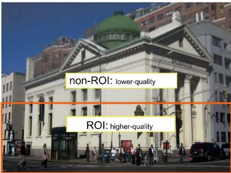
As illustrated below, the upper screen may contain little details of your interest, while the sidewalk on the lower screen is included in an ROI window.
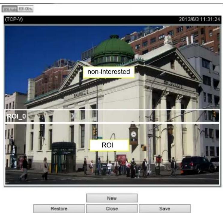
As the result, the lower screen is constantly displayed in high details, while the upper half is transmitted using a lower-quality format. Although the upper half is transmitted using a lower quality format, you still have an awareness of what is happening on the whole screen.
- Hybrid: The major difference between the "Manual" mode and the "Hybrid" mode is that:
In the "Hybrid" mode, any objects entering the non-interested area will restore the video quality of the moving objects and the area around them. The video quality of the associated non-interested area is immediately restored to normal to cover the moving objects.
In the "Manual" mode, the non-interested area is always transmitted using a low-quality format regardless of the activities inside.
Quality priority: (Help)

- Quality priority: Use the slide bar to tune the quality contrast between the ROI and non-interested areas.
The farther the slide bar button is to the right, the higher the image quality of the ROI areas. On the contrary, the farther the slide bar button to the left, the higher the image quality of the non-interested area.
In this way, you may set up an ROI window as a privacy mask by covering a protected area using an ROI window, while the remaining screen become the non-interested area. You may then configure the non-interested area to have a high image quality, or vice versa.
You should also select the Maximum bit rate from the pull-down menu as the threshold to contain the bandwidth consumption for both the high- and low-quality video sections in a smart stream.
Audio
The Audio window allows you to configure all audio codec, sampling rate, and Microphone input gains. Depending on design of the camera models, some codecs may not be available. Also, there are cameras that come without embedded microphones.
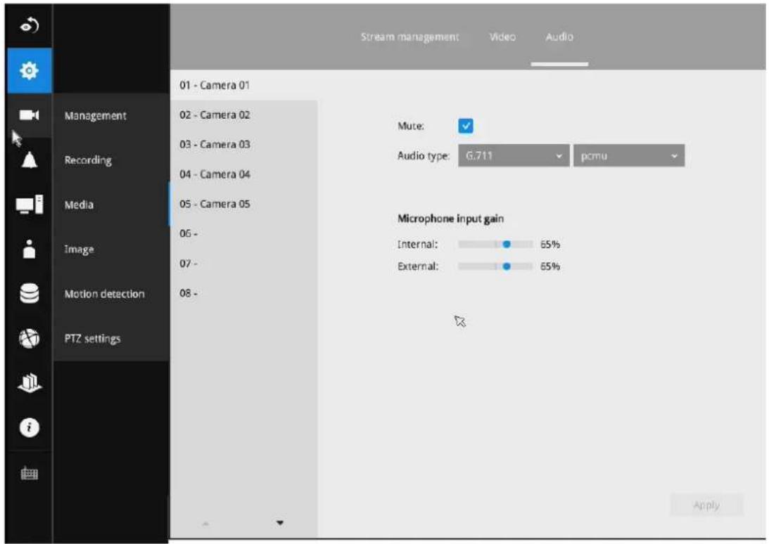
3-5-6. Settings-Camera-Image

Display
The Display window allows users to tune the image display options:
- Video name: the video name is displayed on the title bar that is displayed on each view cell. The screen shot below shows a name as "Speed dome."
- Video name and timestamp: Default is enabled. If enabled, the video name and time is displayed on the view cell.
- Power line frequency: Depending on power line frequency of your country, select a matching option, NTSC 60Hz or PAL 50Hz, to avoid image flickering due to unmatched electricity.
- Video orientation: select these options if the image from camera needs to be vertically or horizontally flipped.
- Click Restore to poll for the original settings or click the Apply button to finish the process.
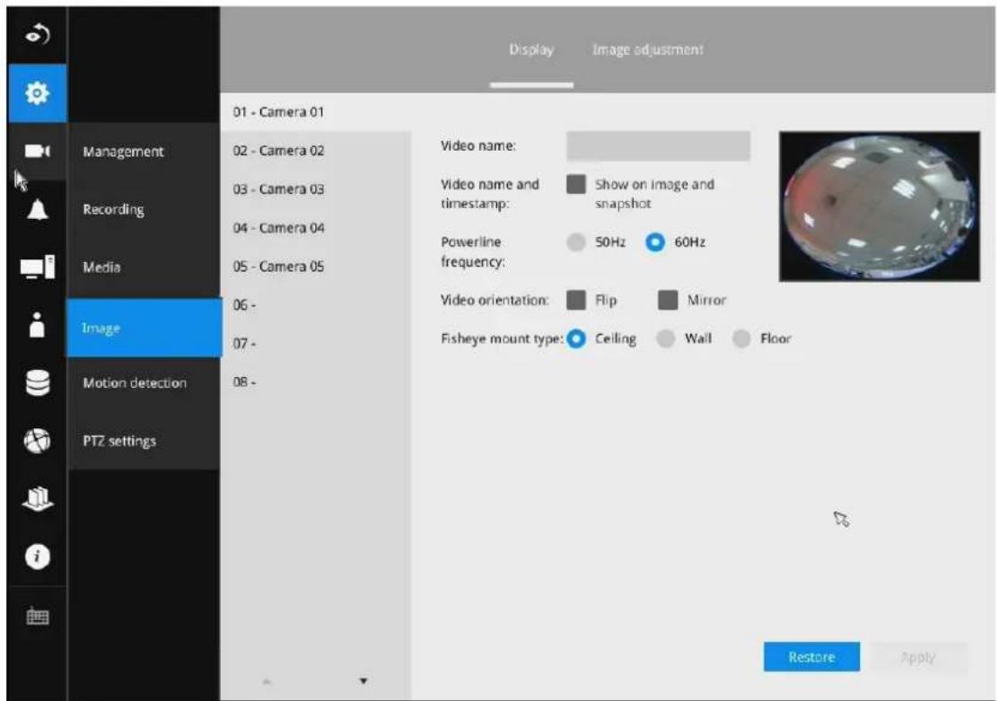
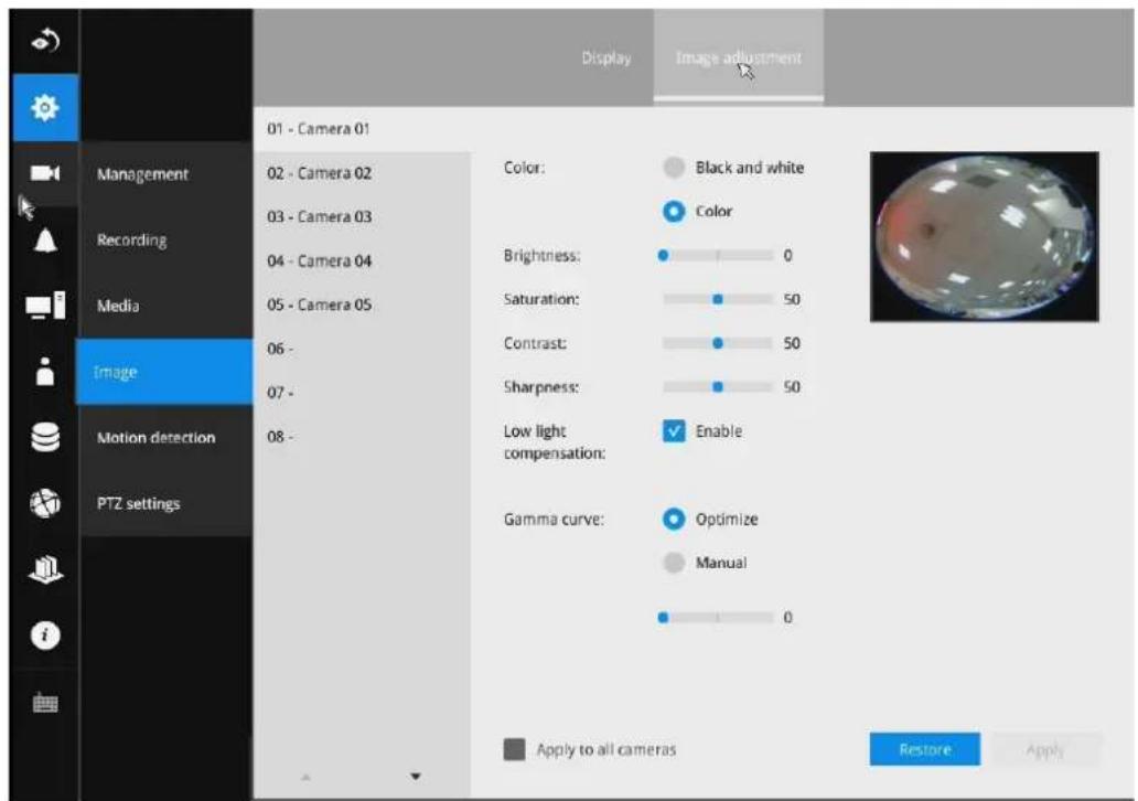
Image adjustment
The Image adjustment window allows users to tune the basics about image display options:
- Color: Select to display image as color or black and white.
- Brightness.
- Saturation.
- Contrast.
- Sharpness.
- High TV line, Gamma curve, low light compensation, etc. The rest of the options depend on the lens and image sensor type of each individual camera. Therefore, the options here can vary. For unique options coming with each individual camera, please refer to their User Manuals for more information.
Click Restore to poll for the original settings or click the Apply button to finish the process. For features common among cameras, you may select the Apply to all cameras checkbox.
3-5-7. Settings-Camera-Motion Detection
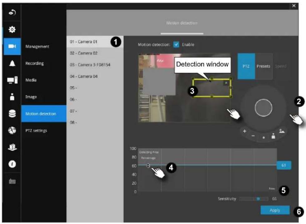
Motion Detection
To set up a detection window:
- Select a camera by a single click.
- Use the PTZ panel to move to a field of view where you want to place a detection window.
- Click and drag to draw a rectangular detection window.
- Pull the detection area level up to a preferred position. An object must be larger than the detection area to trigger an alarm.
- Select a Sensitivity level using the slide bar.
- Click the Apply button for the configuration to take effect.
The sample screen shows a connection with a speed dome camera.
If you already configured Preset positions, expand its menu and click on the presets to move to a position.
3-5-8. Settings-Camera-PTZ settings
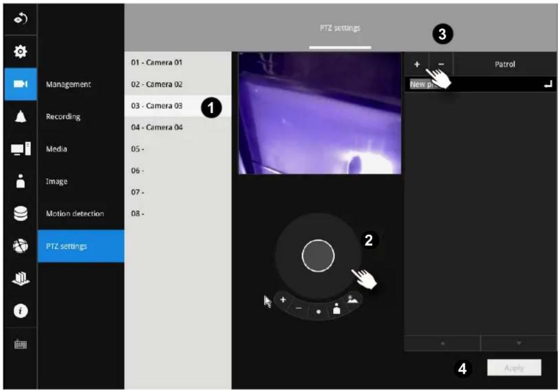
To configure PTZ preset positions:
- Select a PTZ camera by a single click.
- Use the PTZ panel to move to a field of view where you want to designate as a preset position.
-
Click the add button, and enter a name for the position. Press Enter to proceed. Repeat the configuration to create more positions.
-
Click the Apply button for the configuration to take effect.
Note that the PTZ panel can vary with different PTZ cameras.
To configure a patrol:
- Click to enter the Patrol menu. Select a preset position if you want to change its position on the patrolling order.
- Click the up and down buttons to change the position on the order, or click the remove button to disband a position from the order. You can also change the interval to stay before moving from one position to the next position.
- You may then click on the Preview patrol button to see if it runs as expected.
- Click the Apply button for the configuration to take effect.
- Click on the Back to preset list button to return to the preset window.
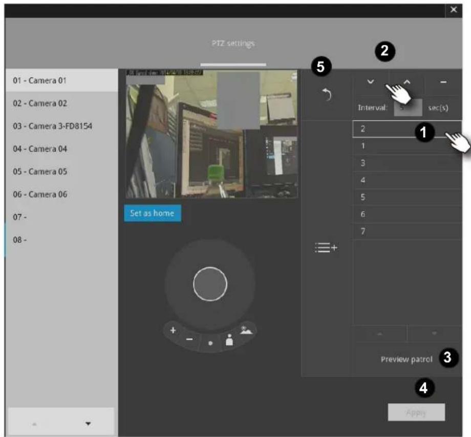
Fisheye camera has its unique options such as the mount types.
Please refer to page 76 or the camera's User Manual for fisheye display mode options.
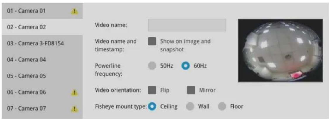
3-5-9. Settings—Alarm—Alarm
The events reported from individual cameras' digital inputs, digital outputs, and motion detection can be accommodated in the NVR system's alarm settings. These events will then be reported or trigger corresponding actions as follows:
- Record the video by the time the event is triggered.
- Reporting events via Email with snapshots attached.
- Sound the onboard buzzer.
- Triggering video snapshot and text message by the occurrences of events to an FTP site.
- Triggering a camera's DO.
- Triggering a PTZ camera(s) for its lens to move to a preset position.
- Sending notification to the VAST CMS software.
- Sending a full screen live view on the connected monitor.
You can create up to 10 instances of alarm.
Hardware connections to DIs or DOs, e.g., window sensors, should be made separately. The motion detection configuration can be made in the Camera configuration window.
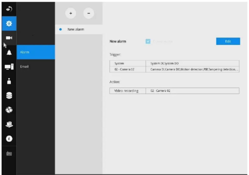
When an alarm is triggered, a message prompt will appear on the Liveview or any configuration window.
14:14
2018.02.22

GPS
Below is a glimpse of alarm sources and alarm actions:
| Sources Actions | |||
| System DI Video recording ▶video footage | |||
| System DO Email snapshot ▶snapshots | |||
| Disk failure Buzzer | |||
| Disk full ▶FTP ▶snapshots | Tilt-Zoom | ||
| GPS disconnected Camera DO | |||
| G-sensor Pan-tilt-zoom ▶Pan-Tilt-Zoom | |||
| Speed limit (XX km/h) System DO | |||
| - Camera sources below | Send to CMS | ||
| Camera DI Send video to full screen | |||
| Camera DO | |||
| Motion detection | |||
| PIR | |||
| Tampering detection | |||
| Camera disconnected | |||
| * Camera DI/DO, motion detection, and tampering are not supported for ONVIF cameras. | |||
To create an alarm,
- Click on the Add button

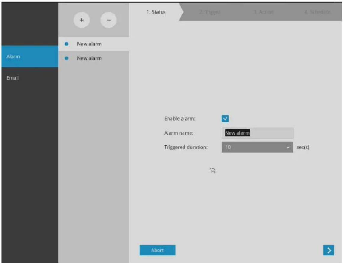
You can manually enter a name for the current setting. You can enter up to 16 numeric or alphabetic characters for the name, including symbols such as [0-9][a-z][A-Z][_]. You can also designate the interval between one alarm and the next triggered alarm to avoid the situation that the alarms can be too frequently triggered.
Click on the next button > to proceed.
Please note that on a fisheye camera's Motion window, you can click and move the corner marks of a window to change its shape. The Motion window does not have to be a square.
- On the Trigger window, select system triggering conditions, or one or more cameras by selecting their checkboxes. The number of DI or DOs on each camera is automatically detected and displayed through individual checkboxes. The Motion detection function, if there are many detection windows configured on a camera, is all triggered by one checkbox.
Note that the triggering sources will be listed even if the camera is currently not connected.
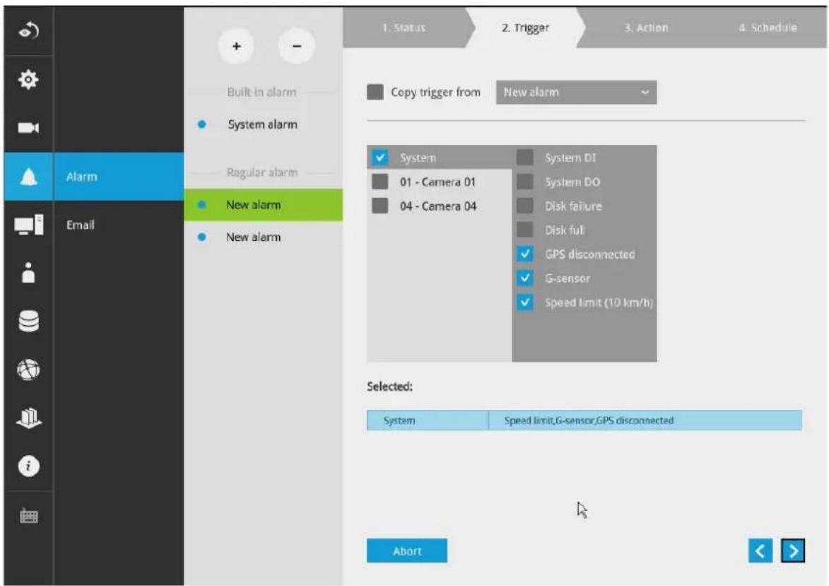
You may also select the "Copy trigger from" menu to borrow the setting you previously configured.
Click on the next button > to proceed.
Note that the GPS and G-sensor configuration, such as vehicle speed limit, is configured in the GPS & G-sensor window.
The following can apply with the GPS and G-sensor configuration:
- G-sensor event: Applies when a vehicle receives impact, or accidents occur.
- When the vehicle over-speeds.
-
GPS disconnected: When the GPS signal vanishes.
-
On the Action window, you can select the Action type from a drop-down menu. The configuration details of each action type is discussion below.
4-1. Recording—When an event is triggered, the selected camera will record a video footage of the length defined by the pre-/post-event setting, to the NVR system.
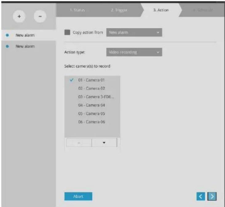
4-2. Email—The Email action sends an Email to the administrator along with a snapshot of the event.
To configure Email notification, enter valid Email addresses as the Sender and Recipient addresses, an Email subject, and the SMTP server address through which the Email will be delivered. If you need to log in to SMTP server to deliver an Email, enter the User name and password for access to that account.
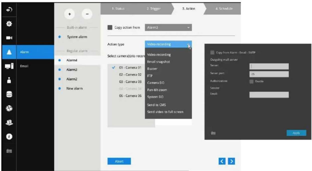
The Email subject and addresses can be composed of 254 characters in numeric or alphabetic characters including: [0-9][a-z][A-Z][_][_-][.][.][@]. You can enter the addresses of multiple recipients. Use semicolons, (;), to separate the addresses of multiple recipients.
4-3. Buzzer—The buzzer is sounded on the occurrence of the event. The buzzer tones are categorized into: Critical (1 long, 1 sec interval) Major (1 long 2 shorts, 1 sec interval), Normal (3 shorts, 2 sec interval), Minor (2 shorts, 2 sec interval), and Notify (2 very shorts) depending on the importance of an event. Select a Buzzer modulation from the drop-down list.
A long tone has a duration of 1 second, while a short tone 0.5 second. A very short tone lasts only for 0.1 second.
Select how many times the buzzer tones will be repeated on the occurrence of an event.
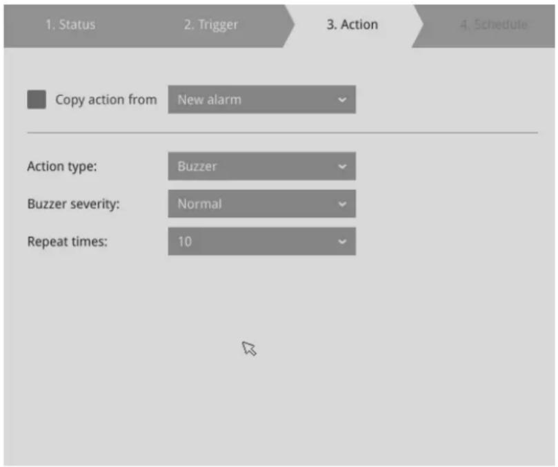
If events of different importance are issued at the same time, e.g., one major and one minor event, system will ignore the minor event and sound the buzzer tone for the major event only. The buzzer can be sounded either by the Alarm actions or the system events. If Alarm actions and system service events occur at the time, Alarm actions have the higher priority.
If multiple Alarm actions occur, the currently-sounded events can be depleted by the new event.
There are conditions that the system will sound the buzzer, and the conditions are not configurable:
- Disk failure—missing drives or SMART detected failures.
- Disk full—the free space is too small for recording tasks.
4-4. FTP-Snapshots from specified cameras can be uploaded to an FTP site on the occurrence of an event. Enter the FTP site address in the dotted-decimal notation, e.g., 159.22.151.20. Enter the login name and password for the user account. You can enter a directory name you prefer on the FTP site. The server port default is 21, a different number between 1025 and 65535 can also be assigned.
The snapshot thus delivered has a size of 320x240 pixels.
If authentication is not applied, login will proceed using the [anonymous] account.
The file names of the snapshot jpeg files will look like this:
[MAC]_[DATE]_[TIME]_[CAMERA_INDEX].jpg - If similar files already exist, an additional index number will be added to the end of file name.
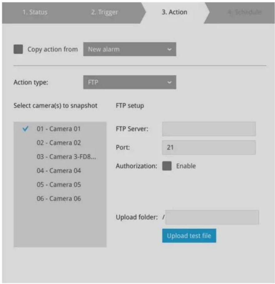
4-5. Camera DO-A triggered alarm triggers a camera's DO, e.g., an alarm siren.
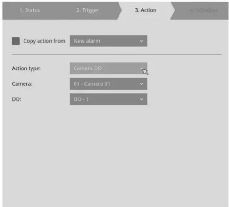
4-6. Camera pan-tilt-zoom-A PTZ capable camera can move its lens to the preset position in case of a triggered alarm. For example, a triggered sensor may indicate an area of interest has been intruded, and a camera's field of view should be moved to cover that area. The precondition is that you properly set up preset positions on your PTZ cameras using a local or a web console.
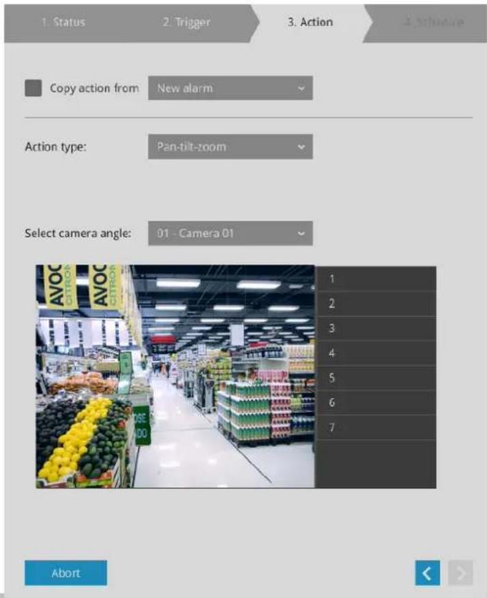
4-7. System DO-A triggered alarm can be used to toggle the NVR's digital output, e.g., to sound an alarm siren.
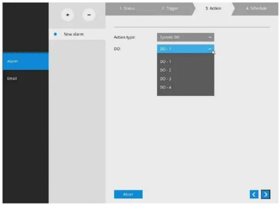
4-8. Send to CMS—An event message will display on your VAST CMS software in the event of GPS signal loss or G-sensor force exceeds configured thresholds.
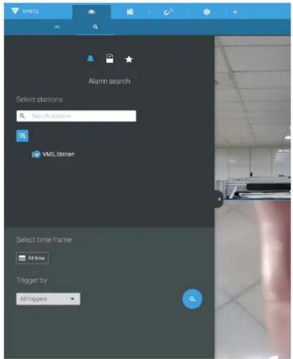
The triggered alarms can be found in the Alarm search panel.
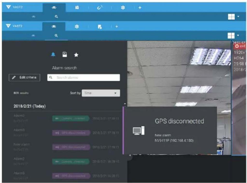
You should also configure a corresponding alarm on the VAST server. Enter the Alarm management window. Select System Event and begin your configuration.
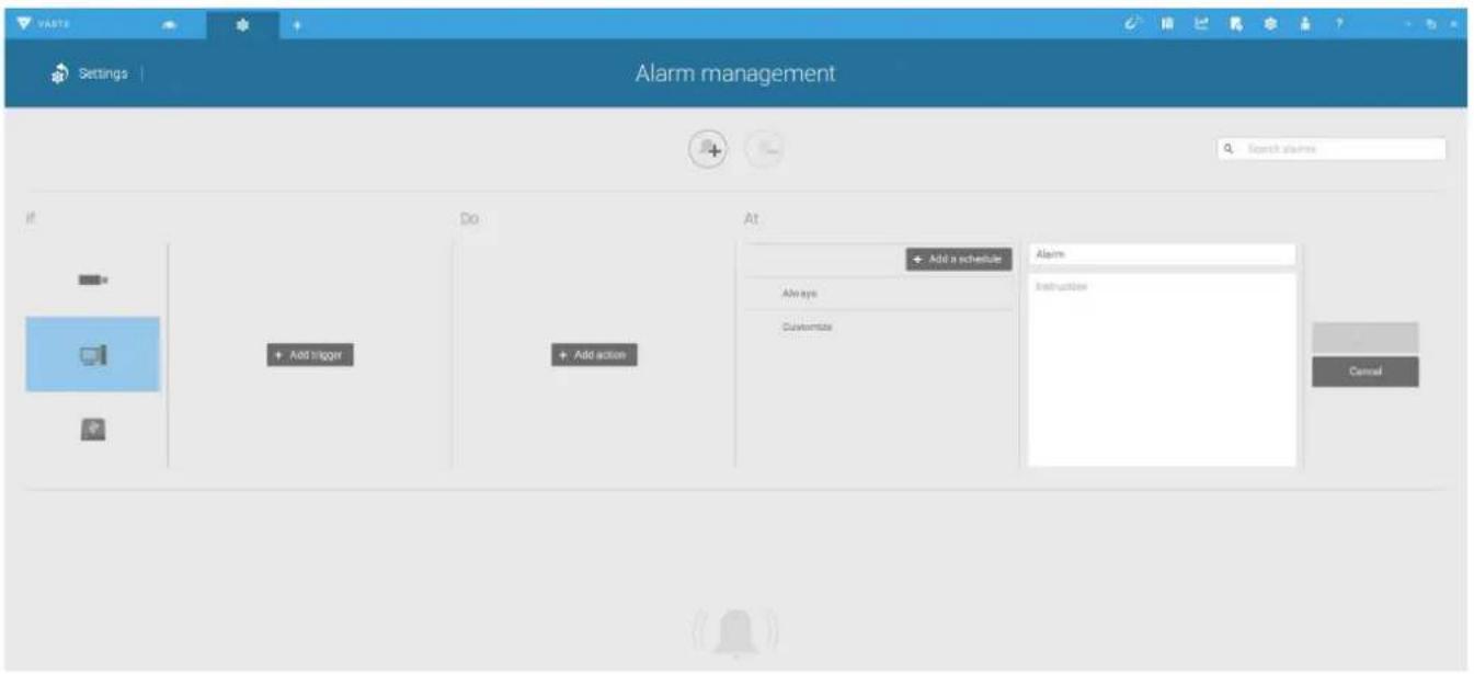
Select NVR and a triggering condition, such as the GPS disconnect, as your trigger.
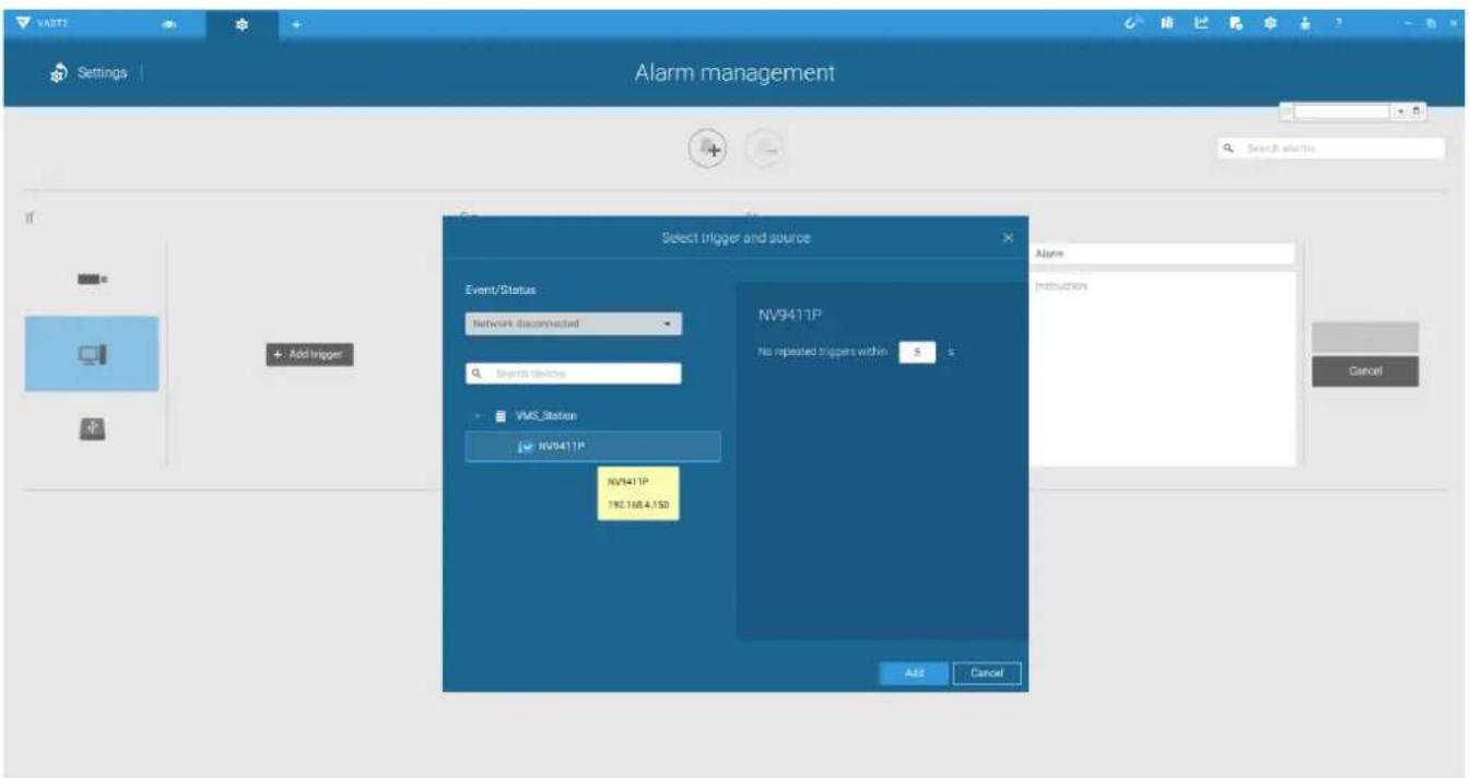
Select the triggering condition from the pull-down menu.
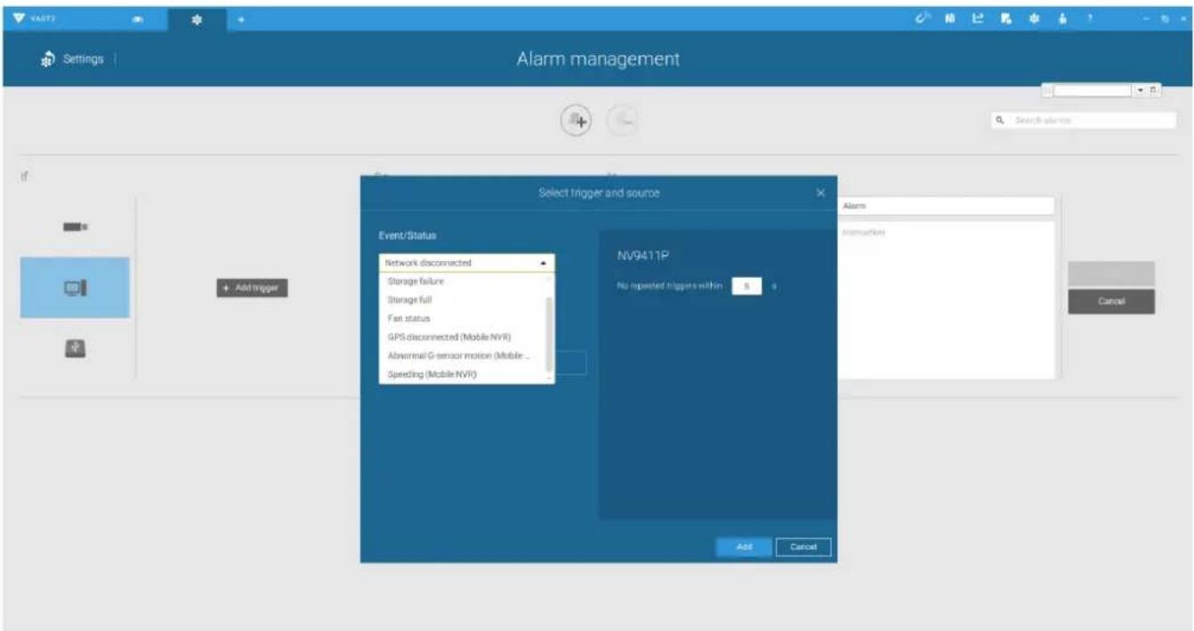
Configure the corresponding action, and proceed with the rest of the configuration. When an event is triggered, such as GPS signal loss, or exceptional G-force is detected, an event message will prompt on screen. You can also search the past alarms to find an event.
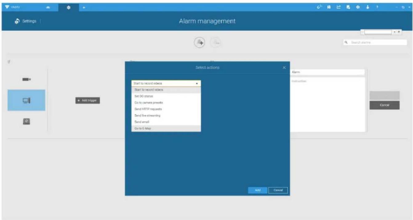
4-9. Send video to full screen—The video feed from a related camera will be displayed on the occurrence of a triggered condition.
- On the Schedule page, you can select to activate or de-activate alarm triggers throughout a specific timeline. For example, in some situations you can disable the alarm triggers during the office hours, and choose to enable the triggers only during the off-office hours.
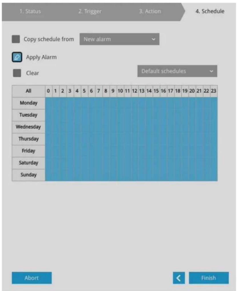
- Click Finish to end the configuration.
- Repeat the process above to create more alarms according to the needs in your surveillance deployment.
3-5-10. Settings—Alarm—Email
This window provides an interface where you can configure the connection to a Mail server. Via the Mail server, the system can deliver Emails containing system alarm messages to multiple receivers. A reachable Mail server and Email accounts must be provided before you can apply the settings.
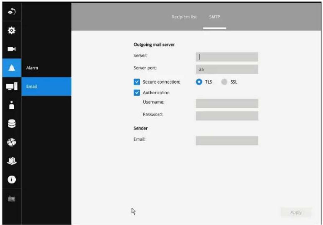
The configuration options are identical to those found in the Email configuration in Settings–Alarm window.
3-5-11. Settings–System–Information
On this window, you can configure the following:
- Change the system name. Using a name in different languages is supported via a web console.
- Select the UI text language.
- Configure system time, time zone, and if you are connected to a DNS server where Auto Daylight Saving time can be applied, you can acquire the associated setting from a server within your network. You can use the Auto Setup button to automatically update the daylight saving configuration. A system reboot is required.
You can also manually update the daylight saving profile in the GZ format using the Import file button below.
- Click the Apply button for the configuration to take effect.
Note that if NTP time server configuration (Auto) is preferred, the system will automatically configure all cameras to be listening to the system, and therefore to the same time server.
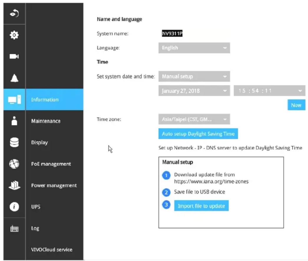

IMPORTANT:
Changing system time can produce disruptions to the existing recordings. Turning the current system time back to a time when video recording was taking place can generate duplicate files. And those files may not be playable.
3-5-12. Settings—System—Maintenance
If the need arises for updating system firmware, acquire the update from VIVOTEK's technical support or download site. Locate the firmware binaries, and click the Import button. The upgrade should take several minutes to complete. Note that during the upgrade, the recording task will be interrupted.
On this window, you can perform 4 maintenance tasks:
- Update firmware—Download firmware and save it to a USB drive in the FAT format, attach the USB device to the NVR for firmware upgrade.
-
Update device pack—A device pack allows you to import associated configurations and parameters for new camera models so that these cameras can be integrated into your NVR configuration. The information in the device pack is related to some tunable parameters.
-
Backup—You can backup your system configuration using the Backup function. Click Backup, a message window will prompt. Click Save to preserve your system configurations.
Select a location for your backup file, then click Save to complete the process. If you back up to a USB thumb drive, that thumb drive must be formatted using the FAT format.
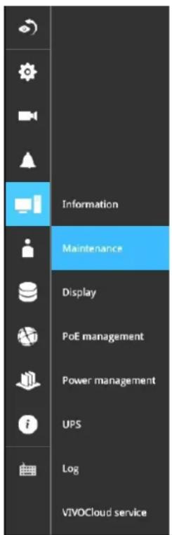
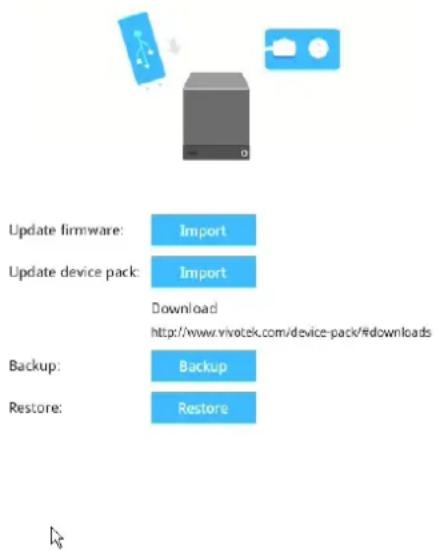
Note that the backup action does not involve the following:
- Recorded videos and database,
-
Alarm records, bookmarks, and bookmarked footages.
-
Restore—If you have a previously-saved profile, you can restore your previous configuration. Click the Restore button.
A file location window will prompt. Locate the backup file, and click Open. The Restore process will take several minutes to complete, and system operation will be interrupted during the process.
3-5-13. Settings—System—Display
On this page, you can configure the system to consecutively display (rotate) cameras' view cells on the Liveview window. For example, if you have 8 cameras in 2 2x2 layouts, the rotation can let you see the live views of all cameras by every few seconds.
You can also enable or disable the Alarm notification.
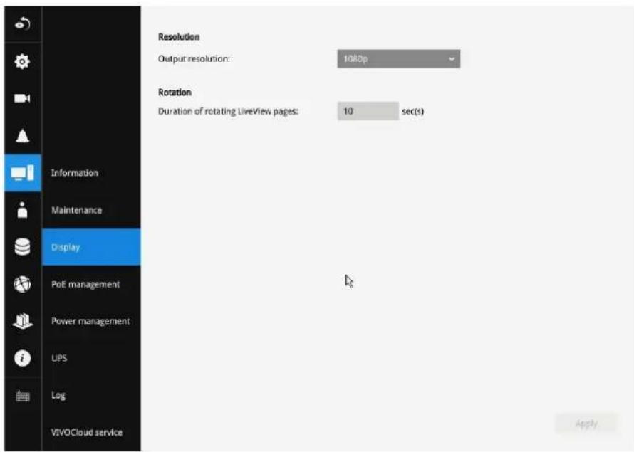
To enable the rotate function, click on the rotate button on the layout panel.
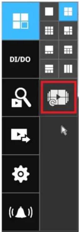
3-5-14. Settings—System—PoE management
When IP cameras are connected to the NVR's PoE ports, their power consumption is constantly monitored, and the power budget is displayed on the PoE management screen.
The following apply to the PoE connections and PoE management:
- Cameras will be automatically enlisted to the NVR. The PoE connection status is polled every 10 seconds.
- For devices that come with multiple video channels, e.g., a video server, each video stream will occupy a video channel.
- PoE Plug and Play takes effect after the initial setup. Any cameras connected thereafter will automatically join the NVR configuration. If you manually delete a camera from list, you should unplug and then re-connect it to the PoE port before joining the network back to NVR.
- The above does not apply to ONVIF cameras.
- The total PoE power budget is 64W. The maximum output for each port is 30W.
- You can manually enable or disable the PoE output on each port, and configure a priority setting for each port (should you need to run the deployment on a tight power budget).
- If port #5, #7, and #8 are configured with Low priority, and power runs short on the NVR. The ports with smaller port number, e.g., port #5, will be powered first. In this case, ports #7 and #8 may not be sufficiently supplied.
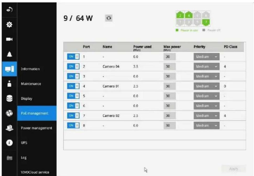
-
The PoE automatic enlistment does not apply for cameras that come with preset credentials, namely, password-protected.
-
The PoE port status can reflect the following situations:
A. PoE enable -PoE is working (port icon displayed in green on the upper-right screen)
B. PoE turned OFF –PoE manually disabled (turned to OFF)
C. PoE turned OFF -Port power overload (under camera name)
D. PoE turned OFF – Total power overload (under camera name)
E. PoE turned OFF -Abnormal power supply voltage(under camera name)
F. PoE turned OFF – Non-standard powered device (under camera name)
G. PoE turned OFF -Port error (under camera name)
- When the NVR has little reserved power budget, and you attach a new camera, the NVR will stop supplying power to the new camera.
3-5-15. Settings—System—Power management
You can configure the system delayed boot up and delayed shuntdown here. Note the function only takes effect when the power line connection is valid.
If the key lock of the tray box is unlocked, the system automatically shuts down.
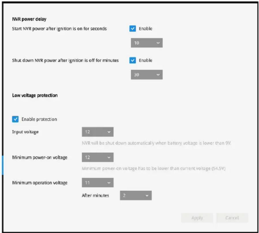
The low voltage protection feature enables the system to be powered down after the low voltage condition persists for a configurable period of time.
3-5-16. Settings—System—UPS
On this page, you can configure the system to gracefully shut down when UPS battery is lower than a certain level. You may also let it shut down when the estimated sustainable time is reached. We support APC Black 500 UPS.
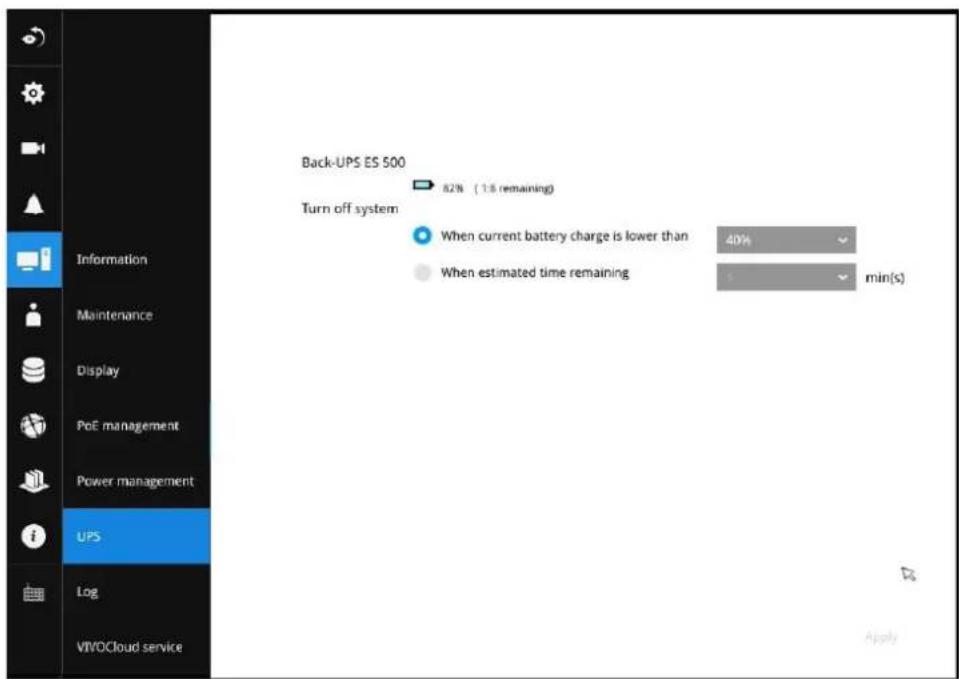
3-5-17. Settings-System-Log
System logs are categorized as System, Recording, User, and Error.
To display system logs, select a range of time and click on the Search button.
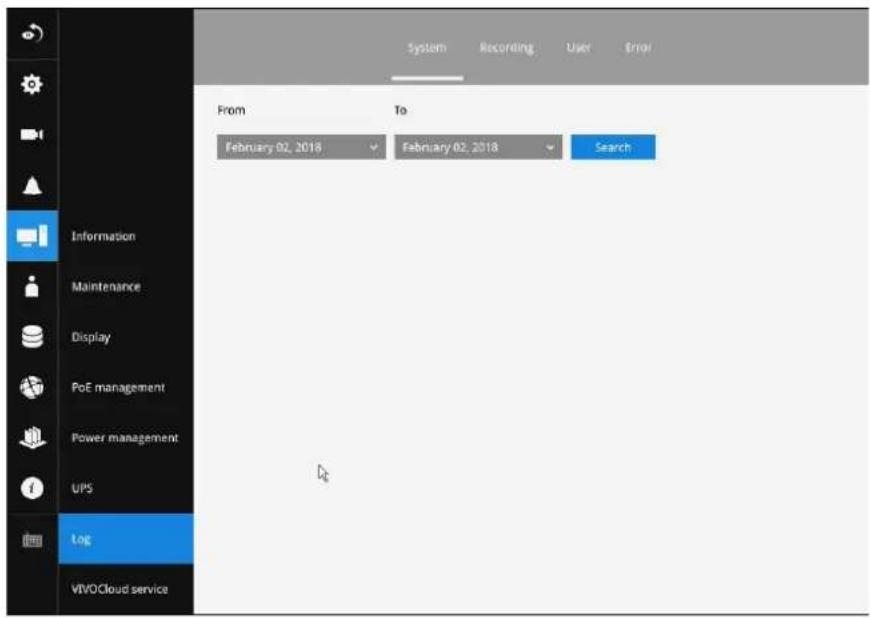
You can search for past logs in each category window.
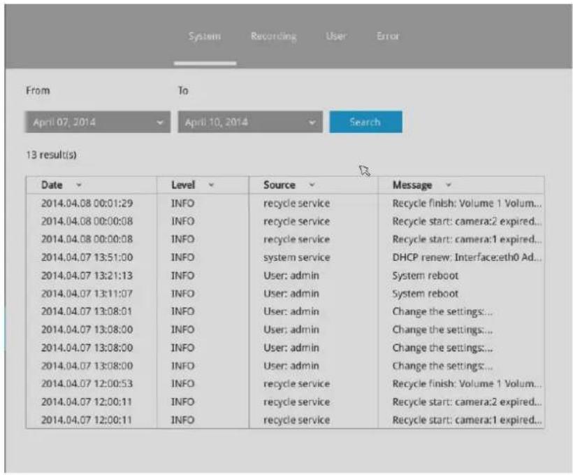
System Recording User error
From
To
April 07, 2014
April 10, 2014
Search
76 result(s)
| Date | Camera | Source | Message |
| 2014.04.10 16:27:25 | 1 | recording service | Recording stop: RTSP Fail |
| 2014.04.10 16:03:30 | 4 | camera service | Camera online |
| 2014.04.10 16:03:28 | 4 | camera service | Camera offline |
| 2014.04.10 16:02:23 | 4 | camera service | Camera offline |
| 2014.04.10 16:02:04 | 4 | recording service | Recording stop: RTSP Fail |
| 2014.04.10 15:59:08 | 4 | camera service | Camera online |
| 2014.04.10 15:59:04 | 4 | camera service | Camera offline |
| 2014.04.10 15:57:53 | 6 | camera service | Camera online |
| 2014.04.10 15:57:07 | 6 | camera service | Camera offline |
| 2014.04.10 15:56:55 | 6 | recording service | Recording stop: RTSP Fail |
| 2014.04.10 15:56:42 | 4 | camera service | Camera offline |
| 2014.04.10 15:56:40 | 4 | recording service | Recording stop: RTSP Fail |
| 2014.04.10 15:56:34 | 4 | recording service | Recording stop: RTSP Fail |
| 2014.04.10 15:56:16 | 4 | recording service | Recording stop: RTSP Fail |
| 2014.04.10 11:19:22 | 1 | camera service | Camera online |
| 2014.04.10 11:19:08 | 1 | camera service | Camera offline |
System Recording User Error
From
To
April 07, 2014
April 10, 2014
Search
4 result(s)
| Date | Source | User name | Message |
| 2014.04.08 08:49:19 | 192.168.6.135 | admin | Login |
| 2014.04.07 13:17:15 | 169.254.132.244 | admin | Login |
| 2014.04.07 13:08:54 | admin | Update layout: {"view"... | |
| 2014.04.07 13:06:55 | 169.254.132.244 | admin | Login |
3-5-18. Settings-User
The User window allows you to create more users, to change user password, and place limitations on users' privileges and administration rights. Up to 16 users can be created, including the default administrator.
- By default, there are two user groups: Administrator and Regular user.
- The regular users cannot access the Settings window, meaning that regular users can not add or remove cameras, make changes to alarm, network, and all other system settings. When users try to access the Settings window, the login window prohibits regular users to log in. There is simply no regular user's name on the login window.
- The administrator users can access all cameras recruited in the configuration; while the regular users can be configured to have access to some or all cameras.
- The system blocks out the video feeds from users who are denied of the access to particular cameras. The alarms and the alarm-triggered recordings from those cameras will also be inaccessible for unauthorized users.
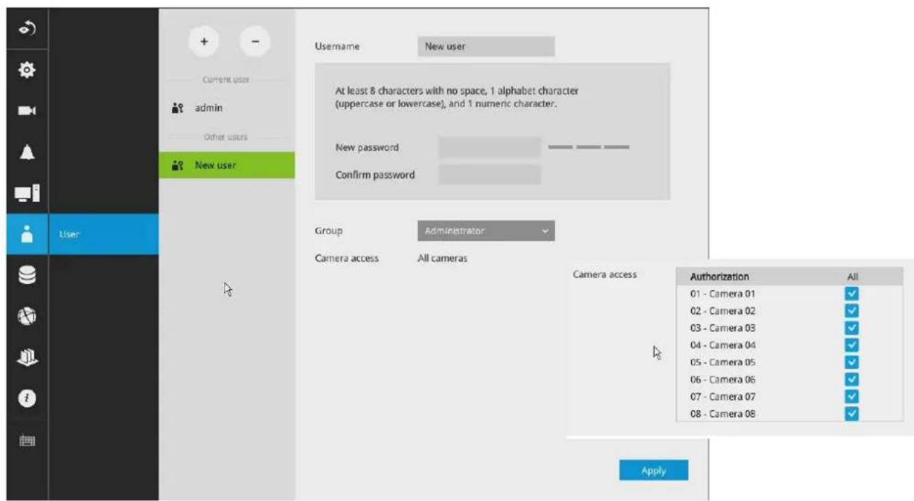

IMPORTANT:
The default administrator name and password are: admin and admin. It is highly recommended to change the default password to prevent unauthorized access to the system.
To create or edit users,
- Select a User group by unfolding its pull-down menu. Select either an Administrator or regular user as the user group.
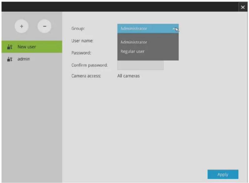
- Enter the User name and password. The max. number of characters for a user name is 64, with alphabetic and numeric characters including [0-9][a-z][A-Z][_]_[]-[.][,][@]. The max. number for password is also 64.
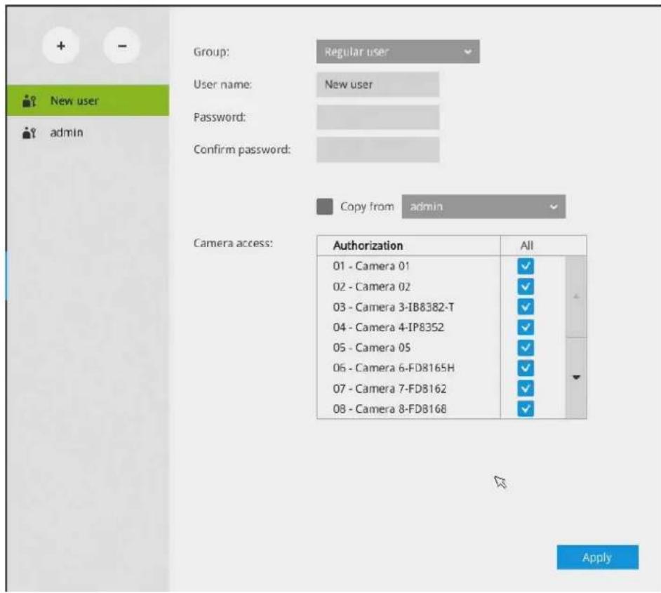
- If you are creating a regular user with limited access to cameras, deselect the checkboxes by the cameras to deny the user access.
- Click Apply to close the configuration window. Repeat the process to create more users.
3-5-19. Settings—Storage
The storage page displays the volume information including physical position, total capacity, used and free space, and associated commands such as Format and Delete. Since each volume contains only 1 hard drive, detailed information about the hard drive is also displayed on this page.
You can format an existing storage volume in situations such as when you need to re-deploy the system elsewhere.
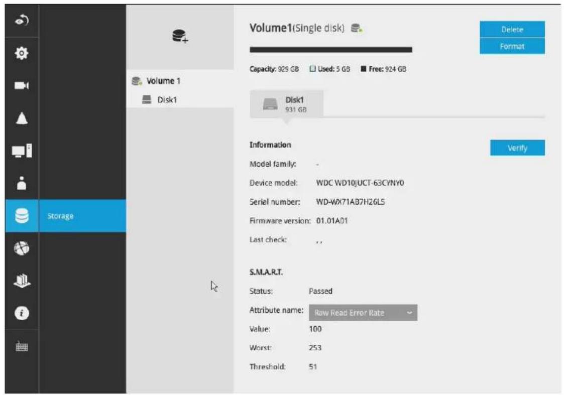
Disk Information:
Model family: The brand name of the HDD manufacturer.
Device model: The disk model name.
Serial number: Serial number assigned to the disk drive.
Firmware version: The version of firmware running on this disk drive.
Last check: The bad block check or S.M.A.R.T. test previously executed on this drive.
Status: S.M.A.R.T. status polled from the disk drive. This is not the results from a manually-executed S.M.A.R.T. test.
Attribute: The various attributes can vary from different HDD manufacturers.
Value: Value for the currently selected attribute.
Worst: Worst value acquired for that attribute.
Threshold: A predefined threshold or triggering value. The threshold below which the normalized value will be considered exceeding specifications.
Raw value: The detected parameters for that attribute.
Status: The judgement made to deem the current reading as OK or failed.
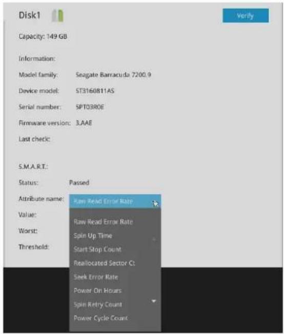
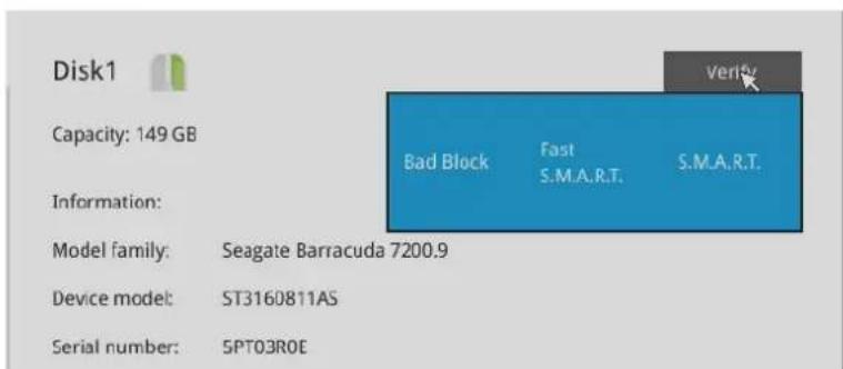
Note that disk verify function requires a volume to be temporarily disabled; namely, the video recording will be stopped before disk verify can be performed.
Verify:
Three types of check disk actions can be initiated through this button.
Bad block check: Performs read/write test to drive sectors to locate bad blocks. This action may take several hours to complete.
Fast S.M.A.R.T. test: Tests the electronic and mechanical performance and disk read performance, including those on disk buffer, read head, seek time, and integrity of drive sectors. The short test is performed on a small section of disk platters, and takes about 2 minutes to complete.
S.M.A.R.T. long test: The long test is more thoroughly and is performed to all drive sectors. The actual completion time depends on drive sizes and the attributes put to test.
The Check disk functions mentioned above, when performed during active I/Os, can consume system resources and cause dropped frames with the recording tasks.

IMPORTANT:
There are conditions that disk drives will not be available for storage configuration:
- The disk drives are performing the Verify process.
- The disk drives considered as "failed" drives by the S.M.A.R.T. self detection.
3-5-20. Settings-Network
Settings-Network-IP
Default Gateway: The NVR gains access to the Internet via Ethernet, Wi-Fi, or LTE (4G Long Term Evolution) wireless WAN. Select a default gateway and start configuration.
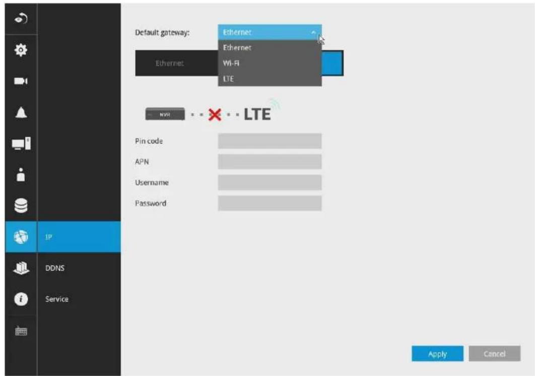

IMPORTANT:
When using LTE, and a PIN is required:
It is very important to use the correct PIN after it is configured. The SIM card will be blocked if the wrong PIN is entered three consecutive times on a locked SIM during the authentication process or when trying to unlock a locked SIM.
You can unblock a blocked SIM card using the PUK code. Contact your service provider for the PUK code.
Prerequisites for Using 4G LTE:
- You must subscribe to a service with a wireless service provider and obtain a Subscriber Identity module (SIM) card.
- If LTE connection is preferred and an LTE module is installed, you need an active SIM card provided by a service provider.
The SIM cards are usually provided in an unlocked state so that it can be used without a Personal Identification Number (PIN). If the SIM is unlocked, it can be inserted into the NVR and used without an authorization code.
- Install the SIM card and the LTE module before configuring the 4G LTE wireless WAN connection.
- Antennas must be installed for the WAN feature to work.
LTE Configuration:
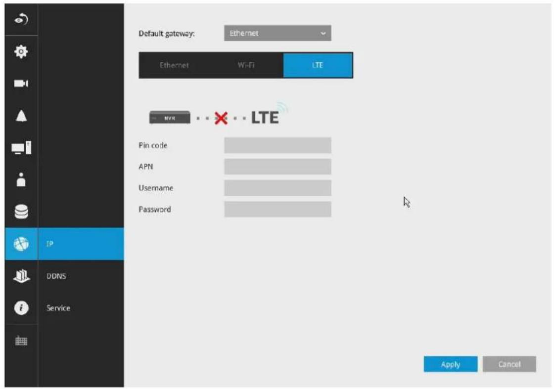
Enter the following on the LTE configuration page:
- PIN: A code (4 to 8 digits long) provided by your carrier to lock or unlock the SIM card.
- APN: specifies an Access Point Name (APN). An APN is provided by your service provider.
- User Name: provided by service provider.
- Password: provided by service provider.
Ethernet Configuration:
DHCP: Default is selected, the server obtains an available dynamic IP address assigned by the DHCP server each time the system is connected to the LAN.
Manual setup: Select this option to manually assign a static IP address to the NVR.
Enter the Static IP, Subnet mask, Default router, and Primary DNS provided by your ISP.
Subnet mask: This is used to determine if the destination is in the same subnet. The default value is "255.255.255.0".
Default router: This is the gateway used to forward frames to destinations in a different subnet. Invalid router setting will fail the transmission to destinations in different subnet.
Primary DNS: The primary domain name server that translates hostnames into IP addresses.
Secondary DNS: Secondary domain name server that backups the Primary DNS.
When finished with the network settings, click on the Apply button.
IP Configuration:
Manual setup
IP:
192.168.4.153
Subnet mask:
255.255.255.0
Gateway:
192.168.4.1
DNS server 1:
192.168.0.21
DNS server 2:
192.168.0.22
Wi-Fi Configuration:
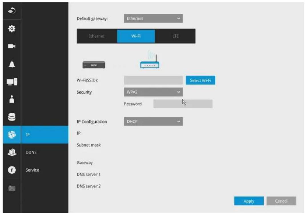
Configuration options:
Wi-Fi (SSID): Enter a known SSID or search for a nearby APhe applicable alpha-numeric characters are [0-9][a-z][A-Z][-], with a max. length of 64 characters.
Security: APs support three wireless authentication settings that use pre-shared keys:
WPA only (PSK) — The AP accepts connections from wireless devices configured to use WPA with pre-shared keys.
WPA2 only (PSK) — The AP accepts connections from wireless devices configured to use WPA2 with pre-shared keys. WPA2 implements the full 802.11i standard. The WPA2 only mode it does not work with some older wireless network cards.
WPA/WPA2 (PSK) — The AP accepts connections from wireless devices configured to use WPA or WPA2 with pre-shared keys.
Password: The applicable alpha-numeric characters are [0-9][a-z][A-Z][-], with a max. length of 64 characters.
When connecting to an AP, the applicable alpha-numeric characters are [0-9][a-z][A-Z][-], with a password length between 8 and 63 characters.
DHCP: Default is selected, the server obtains an available dynamic IP address assigned by the DHCP server each time the system is connected to the LAN.
Manual setup: Select this option to manually assign a static IP address to the NVR.
Enter the Static IP, Subnet mask, Default router, and Primary DNS provided by your ISP.
Subnet mask: This is used to determine if the destination is in the same subnet. The default value is "255.255.255.0".
Default router: This is the gateway used to forward frames to destinations in a different subnet. Invalid router setting will fail the transmission to destinations in different subnet.
Primary DNS: The primary domain name server that translates hostnames into IP addresses.
Secondary DNS: Secondary domain name server that backups the Primary DNS.
Settings-DDNS
VIVOTEK provides Safe100.net, as a free DDNS dynamic domain name service for users who want access from the internet or a domain name service for the NVR. VIVOTEK maintains a database of product MAC addresses for the Safe100.net service, and you can apply one domain name for each NVR system.
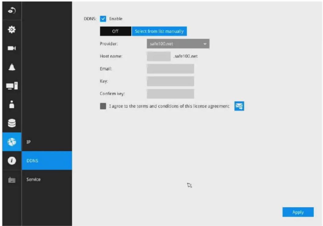
DDNS Enable: Select this checkbox to enable the DDNS setting.
Enter a Host name, Email address, and password twice, and then click Apply to proceed.
Make sure you have internet access.
Click the Register button. The terms of service agreement window is selected from a checkbox at the
bottom. Click to read the license agreement terms.
The acceptable characters for email address are: [0-9][a-z][A-Z][!][#][\$][%][‘][*][+][-][/][=][?][^][_]['][{}][|][}][\~][.]. Two successive periods, [..], are not acceptable. The address filed can accommodate up to 256 characters.
Use only alphabetic and numeric characters for the password. The maximum number of characters is 64.
When completed, a confirm message will prompt. You will also receive a confirm Email. You can now access your NVR system using the xxxx.safe100.net domain name address. Note that access from the Internet should be routed to the private IP assigned to your NVR, using methodologies such as port forwarding, etc.
Settings–Service
By default, the NVR service and video streaming are accessed via HTTP port 80 and RTSP port 554. You can designate a different port number if the need arises. Usually it is not necessary to change these ports. HTTPS encrypted connection is enabled by default.
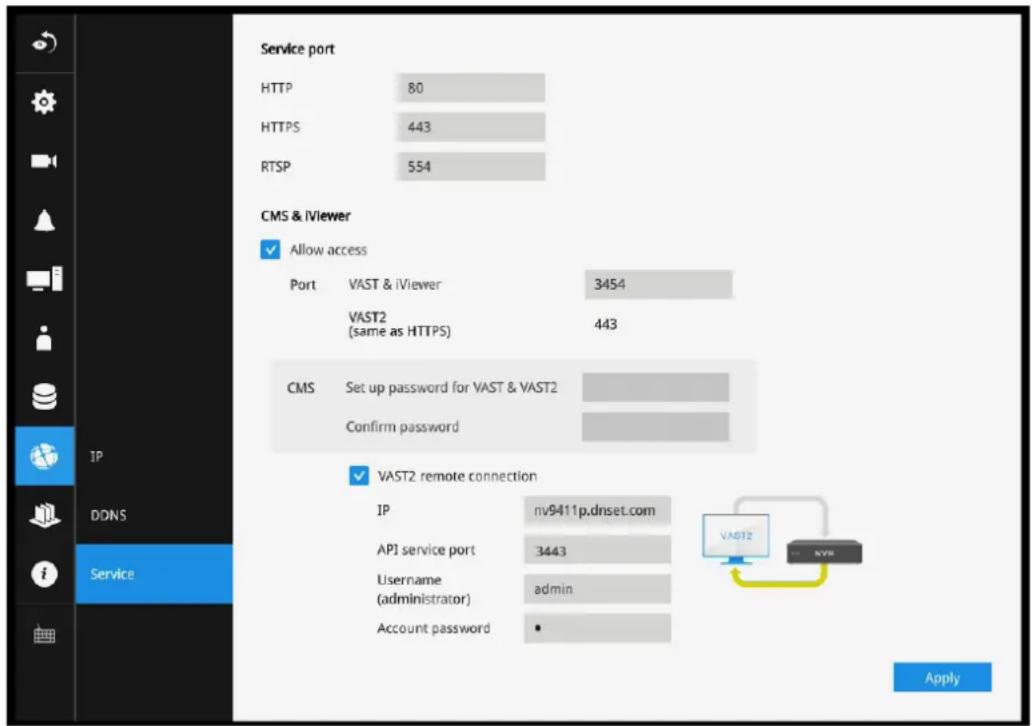
Instead of a web console, you can also access the NVR and the subordinate cameras using the iViewer and VIVOTEK's VAST software. The NVR can be managed as one of the sub-stations in a hierarchical device structure.
Set up a password for access from the VAST server before you can join the NVR to a VAST configuration. For access from the iViewer, you log in using the same user name and password for the login to the NVR.
Below is the screen showing the sub-station recruitment process from a VAST server.
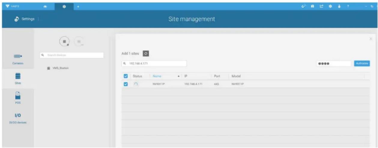
VAST2 auto connection
NAT-traversal with OpenVPN
You can select the "VAST Server with OpenVPN" option when installing the VAST server. A remote connection from NVR via a 3G/4G/LTE network can be made through an OpenVPN tunnel. When the OpenVPN option is selected, an OpenVPN server will be installed with the VAST server.
HMAC authentication and TLS encryption over an encrypted UDP connection are made effortlessly using the traversal methodology.
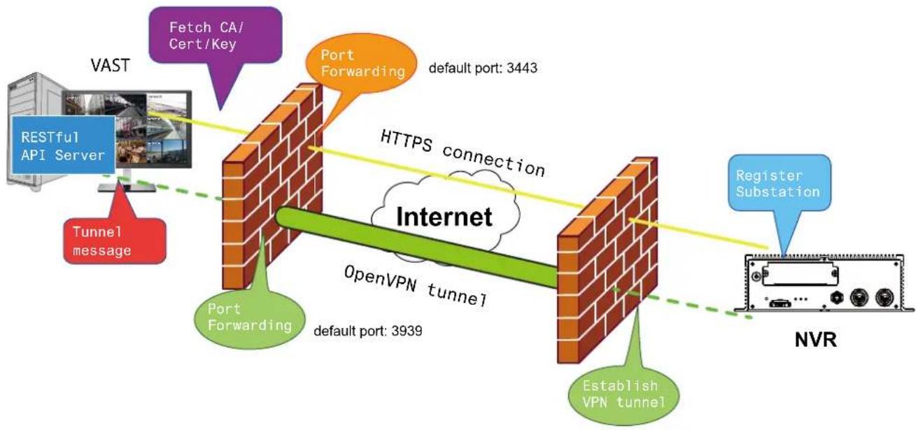
flowchart
graph TD
    A["VAST"] --> B["RESTful API Server"]
    B --> C["Tunnel message"]
    C --> D["Port Forwarding"]
    D --> E["Internet"]
    E --> F["OpenVPN tunnel"]
    F --> G["Establish VPN tunnel"]
    G --> H["NVR"]
    I["Fetch CA/Cert/Key"] --> J["Port Forwarding"]
    J --> K["default port: 3443"]
    L["HTTPS connection"] --> M["Register Substation"]
The sample installation screens are shown below:
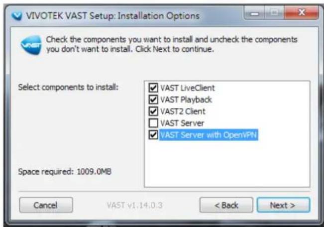
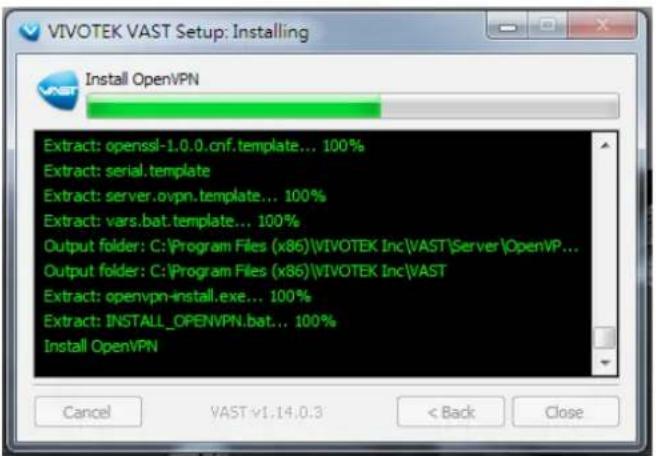
With a remote VAST2 instance that needs to access the NVR via the Internet, you can enter its public IP address and credentials. The NVR runs an Open VPN client that makes remote connection via the RESTful (Repretational State Transfer) API (Application Programming Interface) service to a VPN server running on the remote site. The applicable service port number ranges from 1 to 65534. Default is 3443. The NVR automatically registers with CA cert key and becomes with sub-station over a VPN tunnel. Once set, the VAST2 can automatically connects the NVR.
A public IP or domain name must be configured on the VAST server for the access through the Internet. The IP or domain name can contain alpha-numeric characters [0-9][a-z][A-Z][-] . [-] can not be the beginning or the ending character.
Note that on the side of the VAST server making connection via the OpenVPN, the server/client configuration should be properly configured. On the mobile NVR, a proper gateway setting should be made for VPN connection.
For the server configuration, the configuration file is placed in:
C:\Program Files (x86)\VIVOTEK Inc\VAST\Server\OpenVPN\config\server\server.ovpn
You can edit your VPN IP subnet parameters according to your network configuration. The contents of the editable text file looks like this:
port 3939
proto udp
dev tun
ca ca.crt
cert server.crt
key server.key
dh dh.pem
server 10.6.0.0 255.255.0.0
topology subnet
client-to-client
client-config-dir "C:\\Program Files (x86)\\VIVOTEK Inc\\VAST\\Server\\OpenVPN\\
ccd"
keepalive 10 30
cipher AES-256-CBC
max-clients 50000
persist-key
persist-tun
status openvpn-status.log
log-append openvpn.log
verb 3
mute 20
sndbuf 262144
rcvbuf 262144
tls-server
Note that the NVR and VAST server should have a similar time setting when exchanging certificate information. Otherwise, the mutual handshake authentication process may fail.
Enter the OpenVPN DNS domain name and the credentials on the NVR network service configuration page.
A public IP or domain name must be configured on the VAST server for the access through the Internet. The IP or domain name can contain alpha-numeric characters [0-9][a-z][A-Z][-]. [-] can not be the beginning or the ending character.
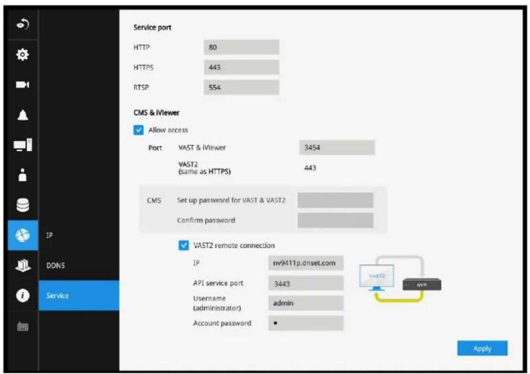
3-6. Devices
GPS & G-sensor
GPS
GPS can be used to detect the vehicle's speed. The speed limitation can be used as a triggering condition. Enter a number as a speed threshold.
G-sensor
The G-sensor can be used to detect unusual maneuvers by detecting acceleration speed information in 3-axial (X, Y, Z) directions. You can change its sensitivity using the pull-down menu, or use the Customized option to manually enter the numbers for g-force (m/s ^2 - meters per second squared). G=9.8 m/s ^2
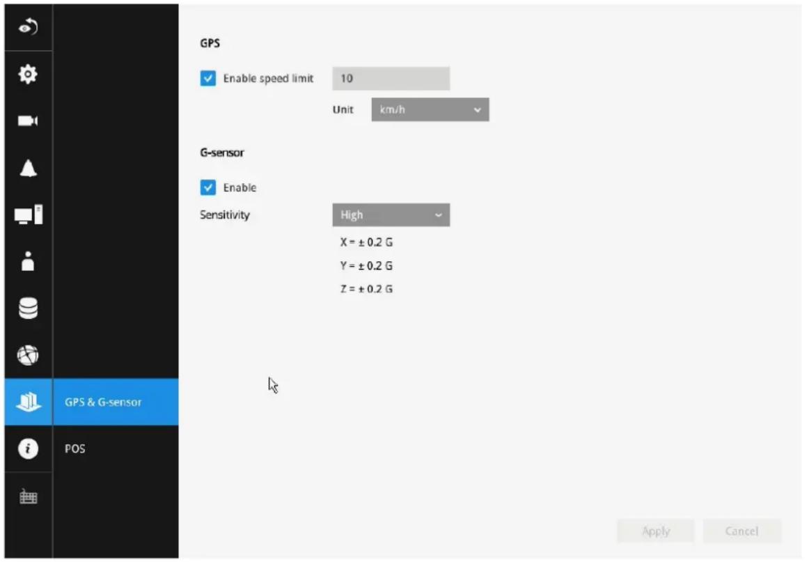
3-7. Information
This window shows the revision number of the firmware running on this machine.
NV9411P
Version: 2.4.0.6 Device pack: v5.9.155
Copyright © 2017 VIVOTEK Inc. All rights reserved.

Section Two
Management over a Web Console
There are two different interfaces on the system:
-
One is connecting mouse and keyboard, and an HDMI cable to a TV screen or monitor. The local management thus made is described in Section One of this manual.
-
The other is accessed through the Ethernet connection. Management via a web console will be described in Section Two of this manual.
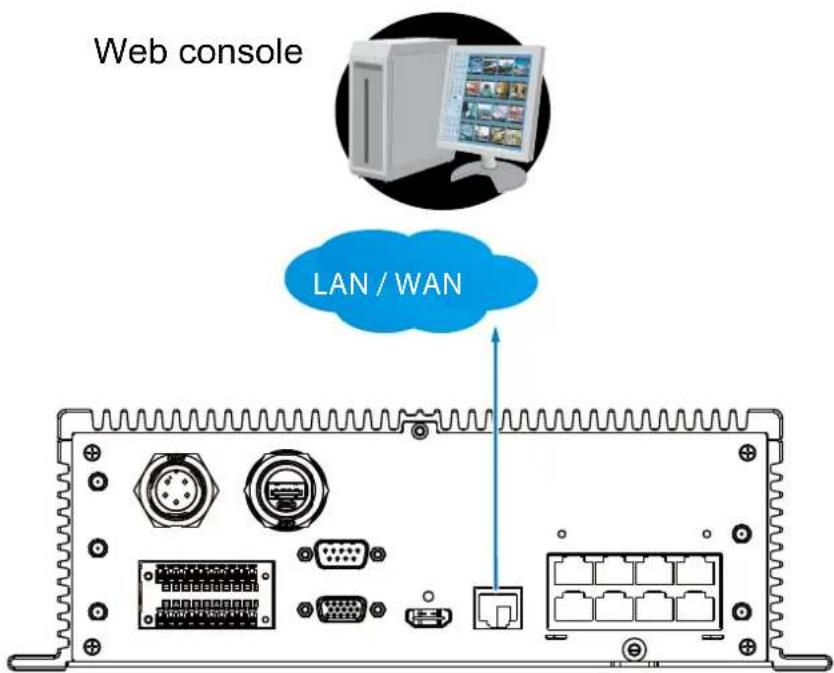
Note that when accessed over the network, the total streaming throughput is 96Mbps.
Chapter Four Login and Getting Started
4-1. Login
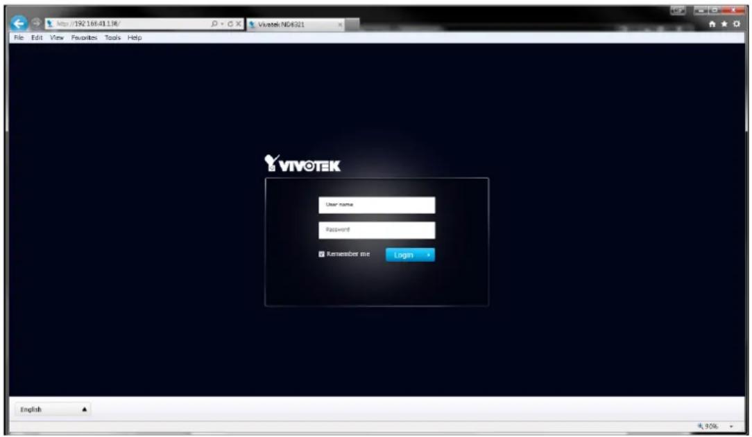
This is the login page on the browser. The minimum for resolution is 1280x960. If you enable the IE7 compatible mode when using the IE8 browser, please disable the compatibility function. While you are in the browser, press F12 to check its status.
It is highly recommended that you should change the default password. Please refer to Settings > Security > User account page to see how to prevent unauthorized access. The system will prompt you if you entered an incorrect user name or password.
Remember me: Your user name will be preserved in browser cookies for two days if you select the Remember me checkbox. The user name will be automatically erased if you do not log in to the system for two days.
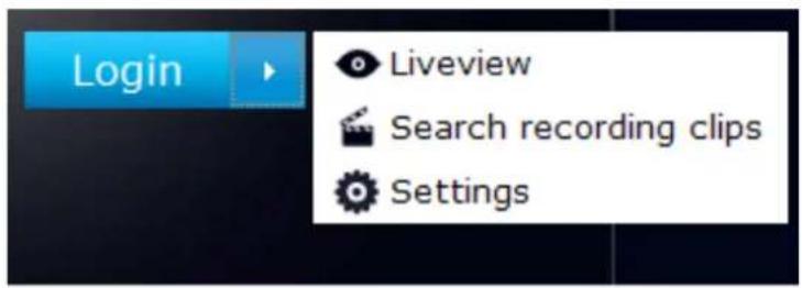
You may login to a different software utility by unfolding the side panel on the Login button.
You can also select a different language using the Multilingual selector menu on the lower left corner of the Login screen. The functional items, menus, and dialogues will then be displayed using the selected language.
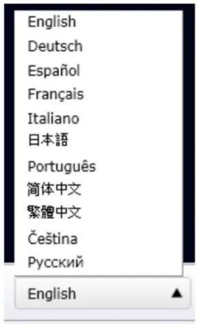
Remember me:
Select the checkbox to save your user name for use on the next login. The user name will be preserved in browser cookies for two days. If you do not login within the next two days, the user name will be erased.
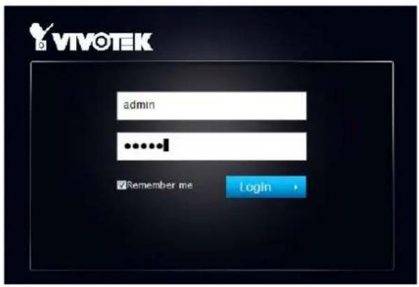
Login errors: below are the login errors that might occur.
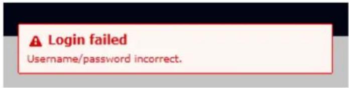
A Login failure can result from the incorrect user name and passwords.
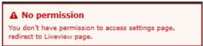
The No permission error occurs when a user logs in using an authentication that has no access rights to the Settings page. He will then be re-directed to the Liveview page.
Login options:
You may also mouse over the Login button to display the login options. You can then enter the Liveview, Playback, or Settings window.
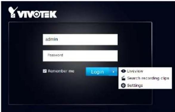
The NVR system features a simple UI structure which consists of a Liveview window, a Playback utility, and a system Settings window. Once logged in, you can move from one window to another by selecting the hot link buttons on the upper right of the screen.
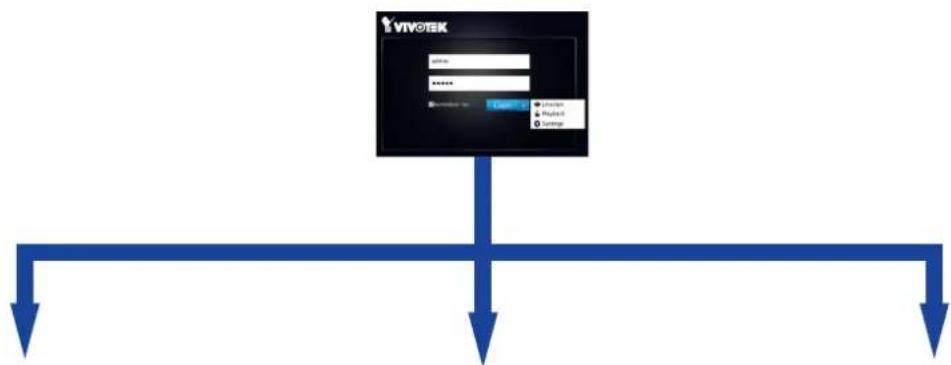
flowchart
graph TD
    A["VIVOTEK"] --> B["Input"]
    A --> C["Processing"]
    A --> D["Storage"]
    B --> E["Output"]
    C --> E
    D --> E
Liveview Search recording clips Settings
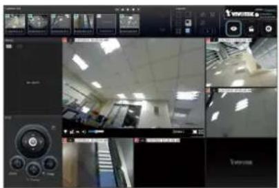
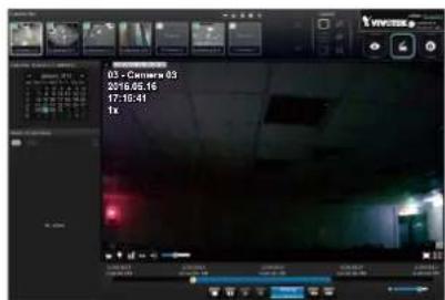
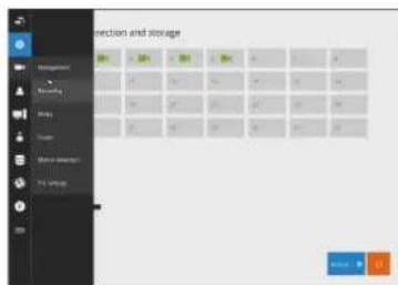

IMPORTANT:
- Before operating the NVR, make sure you have properly installed hard drives and configured the storage volumes. Otherwise, you will not be able to operate some of the system's functionality.
- Since the NVR system comes with 32-bit plug-ins for screen control, if your PC runs a default 64-bit IE browser and you manually enter the NVR's address on the browser, your browser session may malfunction. Instead, if you double-click on the discovered NVR on the IW2 utility, a 32-bit IE browser will open.
- When you log in to the Liveview or Playback interface to stream a live or recorded video, install the ActiveX plug-ins. If it does not prompt when you log in, install plug-ins when you try to playback a recorded video. You may then need to re-start the IE browser console.
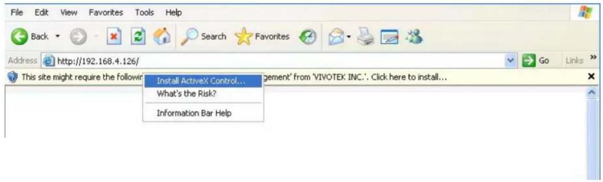
4-2. Graphical Layout and Screen Elements—Liveview
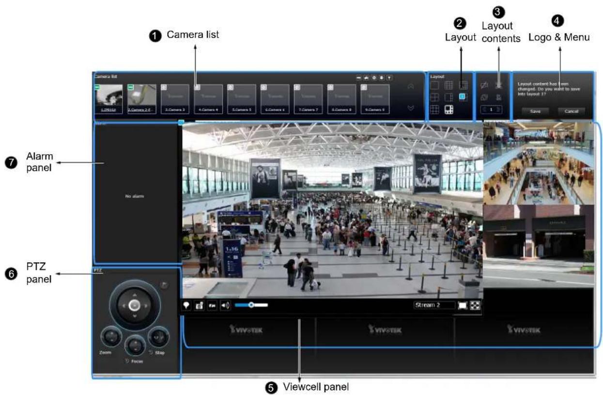
Once you log in, the system defaults to the Liveview page, which provides access to other configuration utilities, live view screen, and other functional panels. The screen elements are described as follows:
| Item Name Description | ||
| 1 | Camera List | Provides a glimpse of all cameras inserted into your configuration. Basic information is also provided along with a screenshot. |
| 2 Layout Provides access to various layouts | ||
| 3 Layout contents Provides functions to extend, rotate, and redo the layout. System DI/DOs are also shown in here. | ||
| 4 | Logo & Menu | Provides access to the Playback and System Settings utilities, as well as system time and logout function. |
| 5 View cell panel Displays video streams from one or multiple cameras. Snapshot, streaming, bookmark, and audio control functions are also available on individual view cells. | ||
| 6 | PTZ panel | Exerts Pan/Tilt control on a selected view cell if the camera comes with mechanical PTZ mechanism. |
| 7 | Alarm panel | Reports alarms transmitted via cameras' DI connections or those by the Motion Detection, Tampering, etc. |
Each panel will be described in further discussions.
4-2-1. Camera List Panel
The camera list displays the recruited cameras by the sequential numbering order you configured in the System Settings utility.
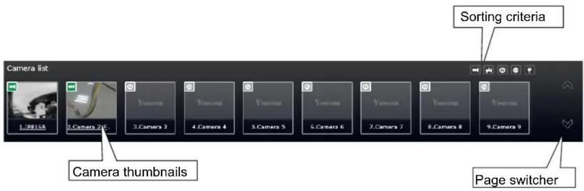
Depending on the size and screen resolution of your monitor, the snapshots of 8 cameras are displayed in this panel. If a user logged in using a credential of a limited access, he may only see cameras that he can access instead of all of the cameras.
To arrange a view cell layout, users can click and drag a camera to a view cell. Once connected, a camera's video stream is displayed in the view cell.
Camera Thumbnail:
A mouse click on the camera name under the thumbnail brings forth the summary of IP address, model name, recording setup and DI/DO information.
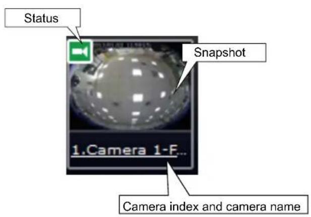
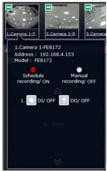
* Snapshot: the camera's image snapshot is replenished every 5 minutes. If a camera is disconnected, the last image taken will be used to represent a camera.
* Camera index & Camera name: Placing the mouse cursor on top of a camera text displays the camera index number and the camera name. You can click on the camera index to display the information box.
* Status:
| Online: the online status can be accompanied by the DI/DO icon | |
| Offline: camera is disconnected. | |
| An unconfigured camera instance | |
| Digital input is triggered | |
| Connected and recording video to system storage | |
| Connected with live streaming | |
| Disconnected or trying to establish a connection |
Sorting criteria
Use the sorting buttons to re-arrange the order of the cameras on the list. Cameras that match the condition will be brought to higher places on the list (front of the order) regardless of its original camera index.
 | Online: the online cameras. |
 | Offline: the offline cameras. |
 | Unconfigured camera instances |
 | Cameras whose Digital inputs have been triggered |
 | Cameras whose Digital outputs have been triggered |

NOTE:
For online cameras, the snapshots on the camera list are refreshed by every 5 minutes, and therefore may not represent the latest occurrences on the surveillance areas.
4-2-2. Layout
| Layout | 1x1 |
| 2x2 | |
| 3x3 | |
| 4x4 | |
| 1P+3 | |
| 1M+5 | |
| User layout #1 | |
| User layout #2 | |
| User layout #3 | |
| User layout #4 |
By default, 5 typical layouts are provided for the user. They include: 1x1, 2x2, 3x3, 4x4, 1P+3, 1M+5, and 1M+12. System default is the 4x4 layout. Cameras that do not fit into the first page of a layout, say, a 3x3 layout, will be displayed on the succeeding layout pages.
Each functional button on the screen is activated by a mouse hover. For example, the below states designate user's operation on a button:
- : not selected.
- : moused over, and is ready for selection.
- : selected, and is taking effects.
Only an administrator can change and preserve a custom layout, and every user can designate a specific layout to be displayed when he/she logs in. The default layout for each user is stored in a browser's cookies.
Whenever changes are made to the current layout, a message prompt will appear on the side of the layout panel reminding you to save your current setting.
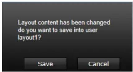
Note that a user who did not log in as an administrator can change a layout, but his configuration changes (with cameras placed on view cells) will not be saved.
User Layouts
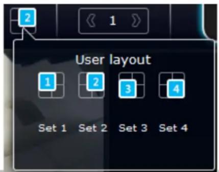
There are another 4 user layouts that can be individually configured. An administrator can insert camera views into these layouts, and save the configuration. These user layouts can be seen by all users.
If you click the Rotate button before the configuration changes can be saved, your configuration changes will be lost.
4-2-3. Layout contents
A few functional buttons are available on the Layout contents page.
 | Clears all view cells on the current layout. | |
 | Full view: extends the view cells on the current layout to the full of the screen. | |
 | Rotate: the rotate function lets system display successive layout pages by the intervals of 10 seconds. The layout page that does not contain camera views will be skipped.A Rotate action will stop when you1. move to another page,2. move to a user layout,3. click to select a view cell,4. remove a camera from view cell. | |
 | Click to display the NVR's DI/DO statuses. | |
 | If your current layout spans across multiple pages, use the arrow buttons to switch from one page to another. The index number of the current page will be shown between the arrow buttons. | |
When your current layout is displayed in a full view, move your cursor to the left center of the screen to return to the default Liveview screen. The Return button will appear.
4-2-4. Logo & Menu
A logout button, system time panel recording clips, and System Sett

and 3 hot link buttons to access the Liveview, Search utilities.

natural_image
Three black square icons with white symbols: eye, film clapperboard, and gear (no text or labels)The system date and time refers to the date and time kept on the NVR system's real time clock.
Due to the limited space for the user name, user name may be partially displayed until you hover your mouse cursor.

IMPORTANT:
Your configuration changes will be lost if you click one of the hot link buttons to move to another utility window. For example, you have changed your Live View layout and then click on the Playback button, you will enter the Playback window without saving your configuration. Save your changes before you use these buttons.
4-2-5. View Cell panel
A single view cell is shown below. Each view cell contains a video stream display area, an information bar, and functional buttons at the bottom. A view cell is displayed in Normal, Focused, or Maximized mode.
- A single click selects a view cell from the View Cell panel, enables its function buttons, and turn it into the Focused mode.
- The 2nd click maximizes the size of the view cell to the full of the panel.
- The 3rd click shrinks the maximized view back into the focused mode.
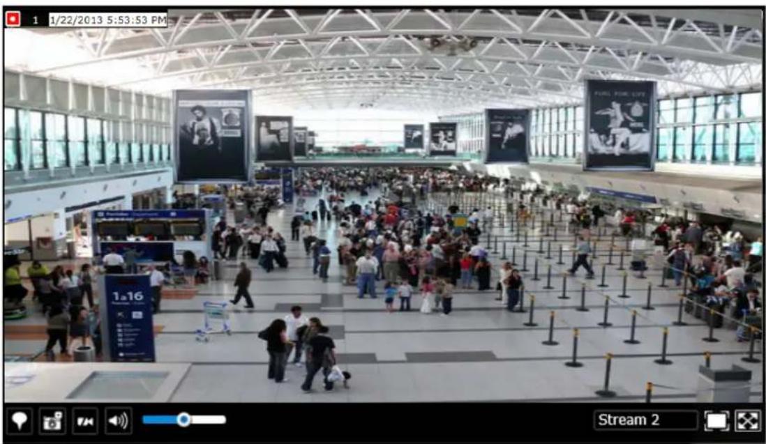
Although the system automatically selects the video stream to display on the view cell, you can still manually select a different video stream from the Stream tab below.
To deselect a view cell and return to the normal view, click on the Restore button at the lower right of the window.
Adding Cameras to View Cells
- Click and drag a camera from the camera list to an unoccupied view cell.
- Double-click a camera on the camera list. The camera will be added to the first available view cell.
To deselect a view cell and return to the normal view, click on the Restore button at the lower right of the window. You can also click on another view cell to continue adding other cameras.
natural_image
Close-up of a hand pointing at a diagonal line on a textured surface, with control buttons below (no readable text or symbols)A view cell attempting to connect to a network camera will look like this. If the connection attempt takes a long time, it may result from network problems or incorrect configuration with video streaming. For example, you may have configured the camera to be streaming a 5MP stream. The NVR uses video stream #1 for recording, and stream #2 from cameras for live viewing. You should then open an individual web console with the network camera to change its video streaming configuration.
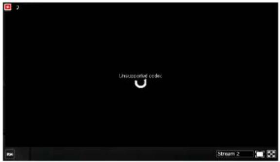

IMPORTANT:
A camera can be inserted into multiple view cells. This way, a camera with a wide field of view, , can simultaneously display different regions of interest on different view cells.
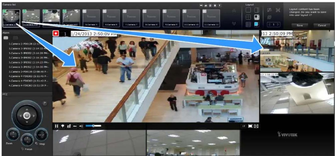
If the current layout already contain the max. number of cameras, e.g., 16 for the ND9441, the following message will prompt.
Not able to add camera
Current layout already has 16 cameras.
If you are using the 16-CH ND9441, there can be more than 16 view cells across multiple layout pages, e.g., on the second page of the 1M+12 layout. Placing a camera in the 17th to 18th view cells will bring out the following message.
Not able to add camera Could not place camera here. Try other view cells.
Information Bar
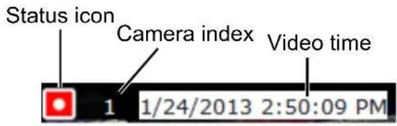
| Status icon Description | |
| Connected with live streaming; a single click on this icon can trigger a manual recording. | |
| Connected and recording video to system storage. | |
| Disconnected or trying to establish a connection. | |

NOTE:
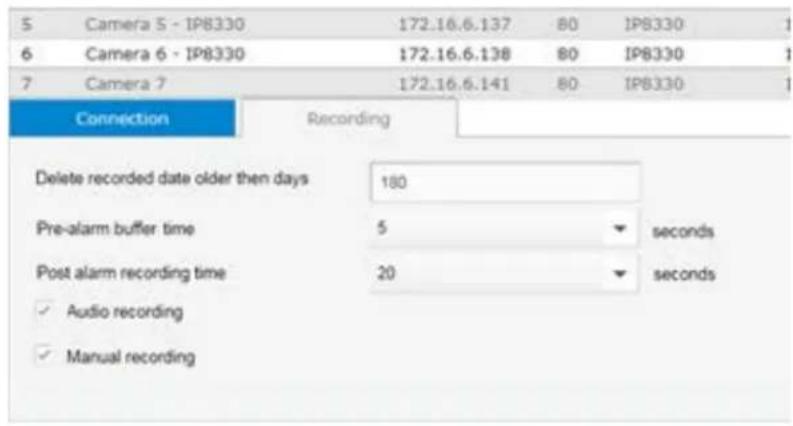
If you disable the Manual recording function on the Settings page, you will not be able to use the Manual Recording function on the Liveview.
Could not start manual recording
Please enable manual recording first
A mouse hover over the status icon will produce the following messages:
| 1. "Connecting..." or "Cannot connect" | Connecting to a camera, or connection problem might have occurred. |
| 2. "Live streaming" Video is being streamed. | |
| 3. "Recording" Currently recording the video stream. | |
Camera index: an index number appointed to a camera following the order you inserted cameras during the initial setup.
Video time: The time configured on the NVR system is displayed here.
The time display format is as follows:
yyyy/m/d/yyyy hh:mm:ss 2014.05.05 16:15:41
Tool Bar Buttons

| Buttons Description | |
 | Resumes streaming. |
 | Pauses a video stream. |
 | Adds a Bookmark (that saves a short description and a one-minute footage from the current feed) |
 | Takes a snapshot. |
 | Removes camera from the view cell. |
 | Mutes (if there is audio input from the camera.) |
 | Unmutes |
 | Stream selector. |
 | Restores the view cell's original position on the Liveview panel. |
 | Maximize the size of current view cell. |
 | Activates the PiP function. |
 | Disables digital zoom (PiP). |
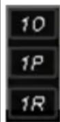 | Fisheye display modes-if the view cell contains video from a fisheye camera, the fisheye display mode selector will be available:1O: the original circular view.1P: the panoramic view.1R: the regional view.Please refer to the fisheye camera's User Manual for more information. |
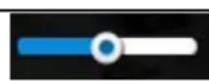
Volume controller
Tool Bar Functions in Details
1. Play and Pause buttons:

These buttons pause and resume a video stream currently being played on your web browser. Note that this operation does not affect the video recording taking place between a camera and the NVR system.
2. Bookmark:

This function allows you to place a bookmark on a recorded stream when you observe a situation from your live view window. The bookmark is preserved as a one-minute footage along with a short description of a particular incident. The precondition of using this function is that the video stream, while you are watching it on the view cell, must be recorded to the NVR at the same time.
To add a bookmark,
- Click on the button,
- Enter a short description that can be as long as 120 characters.

- A confirm message will prompt at the lower right of the screen.
If the current video feed is not being recorded to storage, you will receive the following message:
Below are two bookmarks (yellow tags) shown along with a recorded video in the Playback utility screen. Bookmarks help find and retrieve important moments in a recoded video.
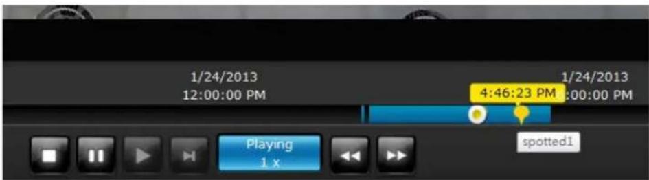

NOTE:
Bookmarks will be erased if the user/system erases the video clips they were appended to. For example, system will recycle storage space by deleting old videos along with their bookmarks.
3. Snapshot:

This button produces a snapshot prompt. You may then right-click on the snapshot image to save it to a preferred location.
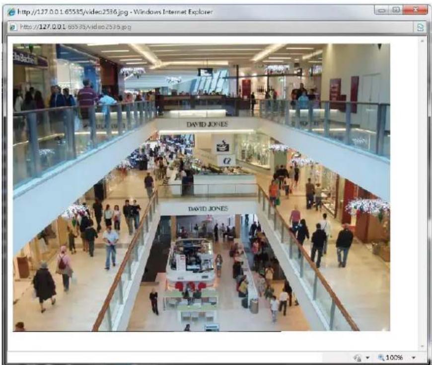
Note that the size of a snapshot is equal to the frame size set for the video stream.
4. Clear:

This button removes camera from the current view cell. The view cell will then be available for other cameras
5. Mute and Unmute:
These buttons stops or resumes audio from a live stream.
6. Restore:

This button restores the view cell's original position on the Liveview panel.
7. Maximize:

This button extends the size of current view cell to the full of the Liveview panel.
8. Activate and Deactivate PiP function:


PiP is short for Picture in Picture, a function that provides digital zoom into a live video. When activated, a Global view window will appear at the lower right of the view cell as shown below. You can display only a portion of the complete video frame as an area of your interest. Using a click and drag on the ROI window, you can instantly move to other areas within the video frame.
You can resize the ROI window by a mouse hover on the lower-right corner of the window until the resize mark appears. The default size of the ROI window is 25% of the Global view. Click on the deactivate button to close the PiP window.
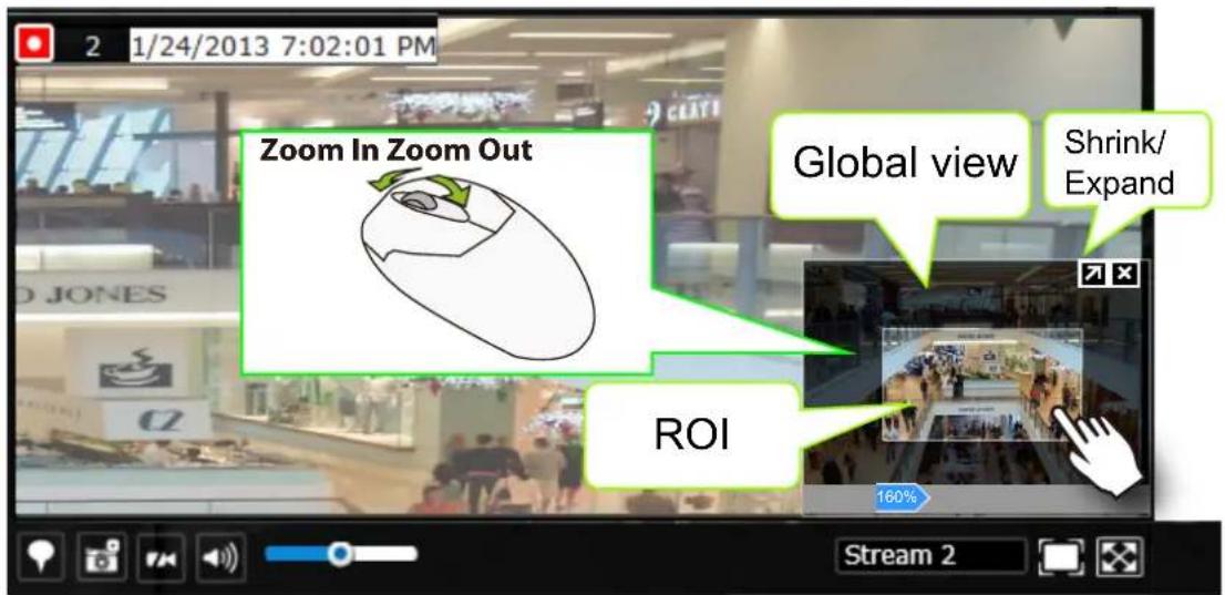
Note that not every camera supports the PiP function.

NOTE:
The Talk function in the two-way audio is currently not supported.
9. Volume controller:
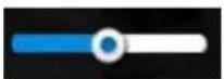
The volume control takes effect when audio input from the network camera is available. Audio is heard only from a focused window, one that you selected by a mouse click from the Liveview panel. Some network cameras do not come with an embedded microphone, and its audio is disabled by system default. The actual sound level is also dependent on the system volume of the PC having a web console with the NVR.
The sound volume configuration will not be preserved when a camera is removed from a view cell, web console is restarted, or when the Liveview layout is re-configured.
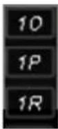
10. Fisheye display modes:
A view mode selector icon appears in a view cell of a fisheye camera. You can click to select a viewing mode. The viewing modes are illustrated as follows:
10 (Original view)
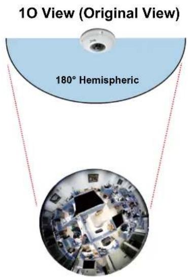
1P (Panoramic view)

1R (Regional view)
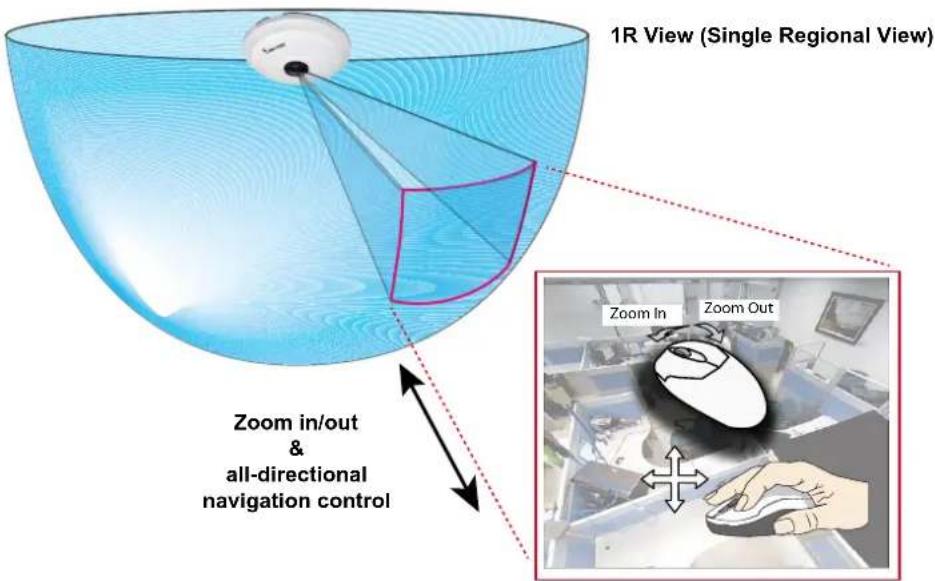
The 1R mode (or rectilinear) provides access to one image section within the hemisphere. You can zoom in or out (using the mouse wheel or PTZ panel) or travel through to other areas within the hemisphere using simple mouse clicks and drags. A single click on a particular object can bring the object to the center of your view window. Click and hold down the left mouse button, and you can swipe the view both horizontally and vertically.
Note that if your fisheye mounting type is set to the Wall Mount type, your screen control in the view cell will be limited to 90° pan and tilt. Make sure your mounting type and camera settings have been properly configured.
Because fisheye lens can cover a wide surveillance area, you can insert a fisheye camera into multiple view cells, and let different regional views display in these view cells. In this way, you can have a glimpse of multiple areas of interest, and the configuration of these different view windows will be preserved when you save your layout settings.
4-2-6. PTZ panel
The PTZ panel takes effect for cameras that come with mechanical PTZ functions. It does not support digital PTZ functions. To utilize its functions, select a view cell populated by a PTZ camera, such as a speed dome.
Depending on the individual functions that come with PTZ cameras, some functions will not be available for every cameras. For example, the zoom controller will not apply for a PTZ camera that comes without a mechanized zoom module, such as PD8136 and PT8133.
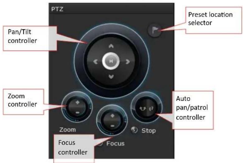
Listed below are the camera models and the types of supported PTZ controls:
| Model (series) P | Pan/tilt controller | Preset location Zoom controller Focus controller Auto | Pan/Patrol controller | ||
| PD Yes Yes No No Yes | |||||
| VS (VS8100 and 8102) | * Depends Depends Depends Depends No | ||||
| VS84xx/88xx Depends Depends Depends Depends | |||||
* If the analogue cameras connected through the video server support PTZ mechanism.

NOTE:
On the Liveview window, currently the Continuous Move and the Click-on-image functions for PTZ cameras are not supported. Neither can you zoom in/out using the mouse wheel.
PTZ presets: If your PTZ cameras have preset locations, click on the button to unfold the preset menu. Click on any of the preset locations to move to the area of your interest. Refer to your camera's User Manual for how to configure preset locations.
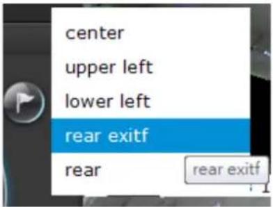
The following message will prompt if the camera has no preset locations.
Pan/Tilt controller: A mouse hover over the arrow buttons activates the arrow button. Use the buttons to navigate to a preferred location.
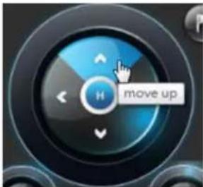
Zoom controller: The zoom controller buttons only apply to cameras that come with an optical zoom module, such as a speed dome camera.
Focus controller: The focus controller buttons apply to cameras that come with focus control over its lens module, such as a speed dome camera.
Auto Focus: If your camera supports the auto focus function, use this button to acquire an optimal focus point.
Auto pan/patrol controller: These buttons provides pan and patrol functions provided that preset locations have been configured on the camera. For a speed dome camera, the pan command tells the camera to continuously pan 360 degrees until it is stopped by a user command. For PZ or PT series cameras, the pan action only takes place once to cover reachable areas.
The Stop button ends a pan or patrol tour.
4-2-7. Alarm panel
To receive alarms from cameras, you need to configure alarm triggers in the Settings > Alarm configuration window (see page 107). Network cameras' digital inputs, digital outputs, or motion detection can all be used to detect conditions in external environments. When the alarms are triggered, you can configure certain kind of actions to take place in response to the alarms, such as:
-
recording the immediate image,
-
sending an Email,
- sounding the buzzer,
4, sending snapshots to an FTP server, - sending event messages to web server,
- moving camera lens to a preset location,
- triggering a camera digital output.
The alarm panel displays the latest 10 alarm entries with the latest alarm on top of the list. The alarm list keeps up to 200 events. Older events will be erased if the number exceeds 200.
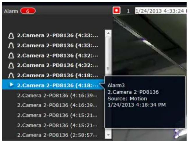
The alarm panel is polled every 10 seconds. A mouse hover on an alarm entry displays full information of the event.
Note that multiple alarms can be triggered by one incident. See page 107 for how to configure the alarm settings.
If an event is configured with a recording action, there will be a play button to the left of the alarm message.
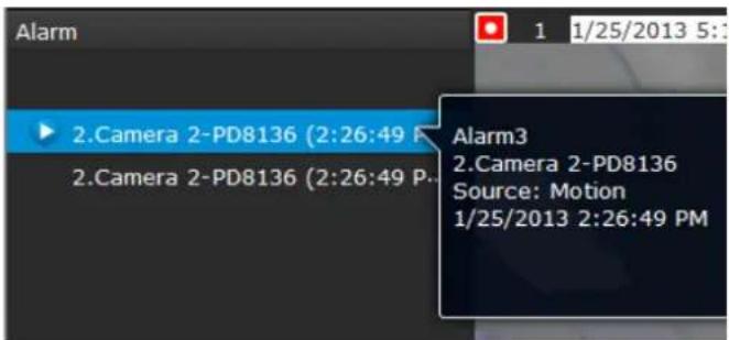
The alarm playback window will begin playback of a footage taken 10 seconds before the occurrence of an alarm. The playback of an alarm-triggered recording will normally last for one minute. If, however, you configured a shorter pre- and post-alarm recording time, your alarm recording may be slightly shorter. The default for pre- and post-alarm buffer time are 5 seconds and 20 seconds.
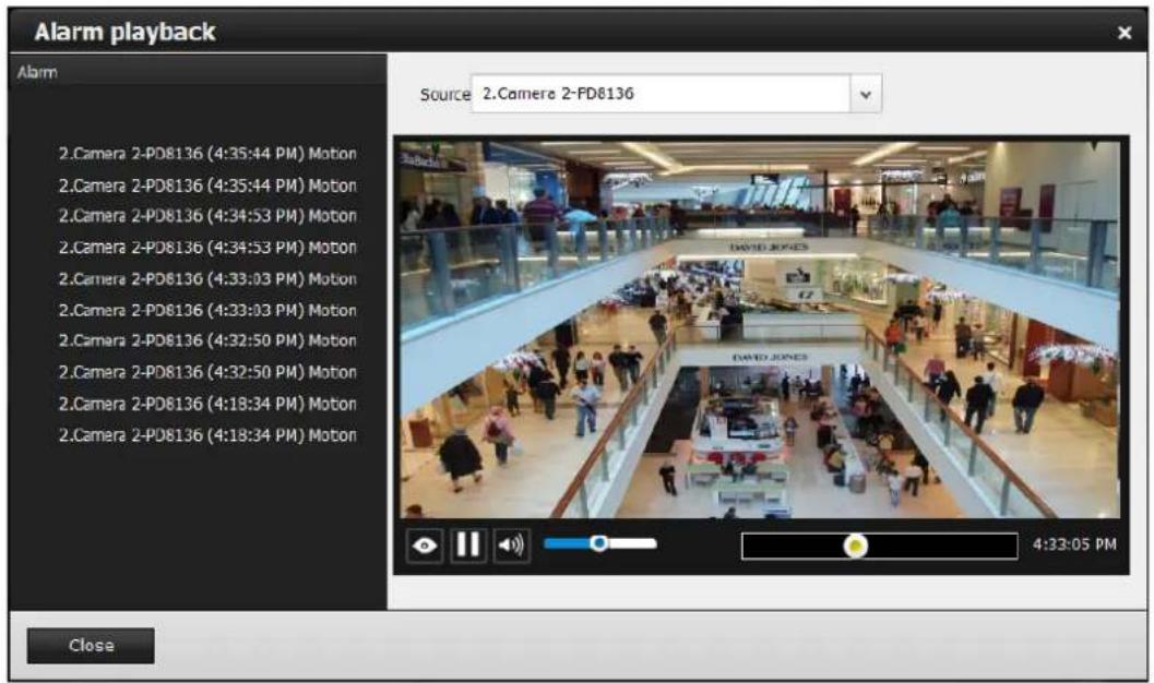
Click and read a text-only alarm will turn off the alarm icon. The alarm icons indicate unread alarms. The number of unread alarms will be listed on the title bar.
Move your cursor over an alarm with a recorded footage. The Play button will become available.
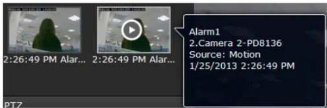

The following buttons are available in the alarm playback window.
| Buttons Description | ||
 | View live video: displays the live view streaming instead of the alarm recording. | |
 | Resumes the alarm playback. | |
 | Begins the alarm playback. | |
 | Pauses the current playback. | |
 | Mute or unmute the audio with the current playback. Drag the controller to change the audio volume level. | |
 | Use the playback slider to quickly change the playback position. | |
 | Click to enable the digital zoom function. | |
Incoming Alarms
New alarms will be indicated by the messages in bold letters, the alarm bell icons, and the increasing number of unread messages 3 on the title bar.
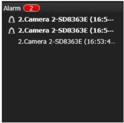
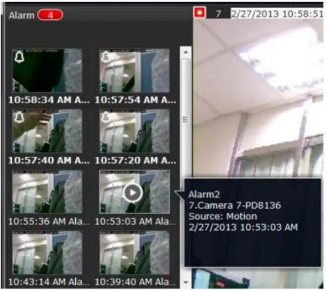
4-3. Graphical Layout and Screen Elements—Search recording clips
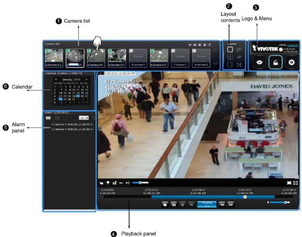
The screen elements of the Playback window are described as follows:
| Item Name Description | ||
| 1 | Camera List | Provides a glimpse of all cameras that have recorded data. Basic information is also provided along with a screenshot. |
| 2 | Layout contents Pro | Provides functions to extend, rotate, redo the layout, and the synchronous playback. |
| 3 | Logo & Menu | Provides access to thePlayback and System Settings utilities, as well as system time and logout function. |
| 4 | Playback panel Dis | plays the playback functions. Snapshot, bookmark, and export functions are also available on individual view cells. |
| 5 | Alarm panel | Reports alarms transmitted via cameras' DI connections or those by the Motion Detection, etc. |
| 6 | Calendar | Shows when the recording took place, and thus enables users to quickly locate a specific part of recording in history. |
4-3-1. Camera List Panel
The camera list displays the 8 recruited cameras by the sequential numbering order you configured in the System Settings window on page 87. The elements in the Camera list on a Search recording clips window are identical to those on a Liveview window. Please refer to page 152 for details on the Camera list panel.
There are two key differences between the Camera List on Liveview and that on the Playback window:
- Users can not click and drag a camera thumbnail to a playback view cell.
- A double-click on a camera does not display video in a view cell. A double-click displays a calendar where days with recorded videos are shown.
To begin playback and search for past recordings,
- Double-click on a camera.
- The Calendar panel will display the days video recording actually took place. And those days will be highlighted by a blue background (as the 25th and 28th in the screen below.)
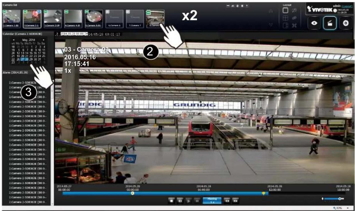
4-3-2. Search Recording Clips Layout
3 types of layouts are provided for the Search recording clips window: 1x1, 2x2, and 1+3.
In the Search recording clips window, users can simultaneously playback up to 4 recorded videos.
 | Clears all view cells on the current layout |
 | Starts or stops the Synchronous playback. |
 | Full view: extends the view cells on the current layout to the full of the screen. |
When your current layout is displayed in a full view, move your cursor to the left center of the screen to return to the default Liveview screen. The Return button will appear.
4-3-3. Logo & Menu
A logout button, system time panel and 3 hot link buttons to access the Liveview, Playback, and Settings utilities. This panel is identical to that on the Liveview window.
4-3-4. View Cells in Search Recording Clips
The view cells in Liveview and Playback windows are similar. Their differences are listed as follows:
- 3 simple layout types are supported as previously described.
- The information bar displays camera index and video time information only.
- The Play and Pause buttons are not available on the Tool bar. One Export function is added on a playback view cell.
The functional buttons on an individual view cell are described as follows:
| Buttons Description | |
| Exports a section of the video into a 3GP or Windows exe file. The length of exported video is configurable to 1, 3, 5, or 10 minutes. | |
| Adds a Bookmark (that saves a short description and a one-minute footage from the current feed) | |
| Takes a snapshot. | |
| Removes camera from the view cell. | |
| Mutes (if there is audio input from the camera.) | |
| Unmutes | |
| Restores the view cell's original position on the liveview panel. | |
| Maximizes the size of current view cell. | |
| Enables the digital zoom. | |
| Disables digital zoom (PiP). | |
| Fisheye viewing modes-if the view cell contains video from a fisheye camera, the fisheye display mode selector will be available:1O: the original circular view.1P: the panoramic view.1R: the regional view.Please refer to the fisheye camera's User Manual for more information. | |
| Volume controller | |
Search Recording Clips Control Panel
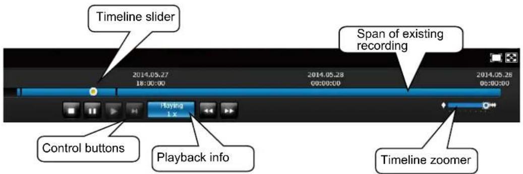

The time slide bar enables quick skimming through the recording. Its functional buttons are described as follows:
| Buttons Description | ||
 | Pause | |
 | Play. This button is available after you manually pause a playback. | |
 | Stops the current playback. | |
 | Next frame. After you paused a playback, use this button to browse video frame by frame. | |
 | Speeds down by 1/2. The slowest speed is 1/8. | |
 | Speeds up. Increases the playback speed, to 2x, 4x, 8x, 16x, and then to a maximum of 32x. | |
 | Displays the current playback status, such as Playing, Pause, play speed, or Stop. | |
 | Timeline zoomer. Use the zoomer to zoom in for more precise skimming. | |
 | Timeline slider thumb. Click and drag this thumb button to move along and reach a specific point in time. A click on the time line will also work. | |
The time line shows the length of existing recording taken on a specific time span. You can use the timeline zoomer to scale down the span of time. For example, if the time span is reduced to 1 hour, then each section on the time line represents 15 minutes of recording. The total time span of a timeline starts from the minimal of 4 minutes, 20 minutes, 40 minutes, 1 hour, and up to a maximum of 24 hours.
In the Synchronous play mode, a change to the zoomer will be reflected by all synchronously playing view cells.
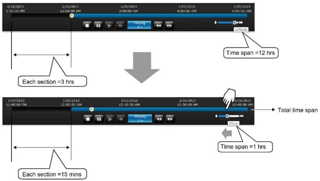
If recordings take place by an event-triggered recording, the intervals between recordings can be down to 1 minute, and the individual recordings will not be easily discernible. In this situation, you can mouse over the timeline to pinpoint individual recording instances.
4-3-5. Alarm Panel
The alarm panel displays the alarms or bookmarks recorded by the day of recording. Two additional buttons are available: Page selector and Alarm filter.
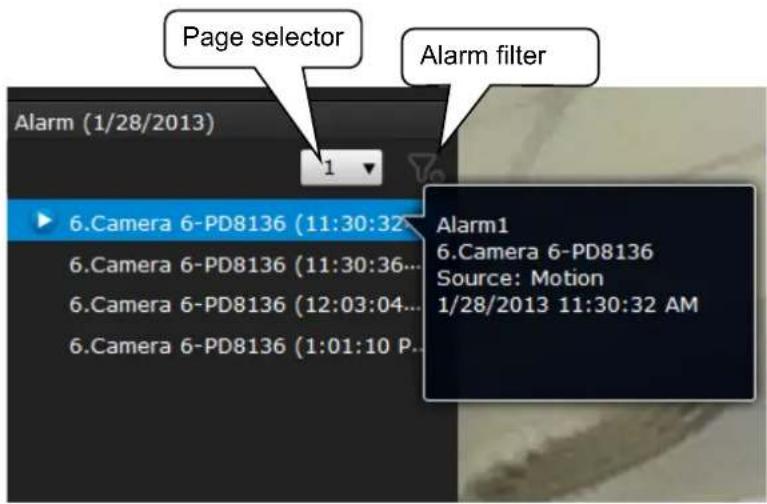
See page 107 for how to configure alarms.
- A playback button will be available with an alarm-triggered recording. The alarm panel in the Playback window also supports the List mode and Icon mode that are similar to that in the Liveview window.
- There can be numerous alarms occurring in a day. Use the page selector to display different pages of alarm entries. Up to 200 entries can appear on one page. Note that the new alarms that occurred seconds or minutes ago may not be instantaneously listed on the page.
If bookmarks are listed in the Alarm list, a bookmark entry will look like this:
Camera index. camera name (time)—bookmark
Alarm filter:
Use the alarm filter to find out specific alarms. Use the check circles below to narrow down your search criteria by Alarm name or alarm type by Motion detection, DI, DO, Tampering, PIR, or those manually marked down as Bookmarks.
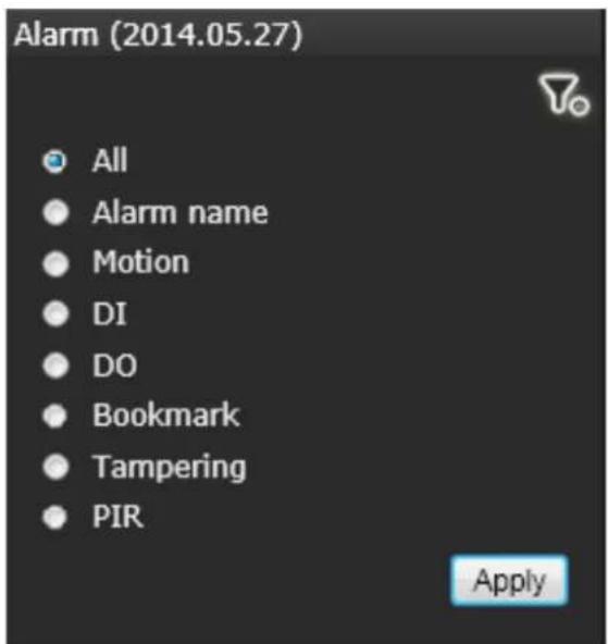
The alarm name is defined by users in the Settings > Alarm page.
4-3-6. Calendar Panel
Double-click on any of the existing cameras to display the Calendar panel. Days with recorded videos will be highlighted in blue regardless of the length of existing recordings that occurred in that day. You may then click on a day to begin viewing the past recordings.
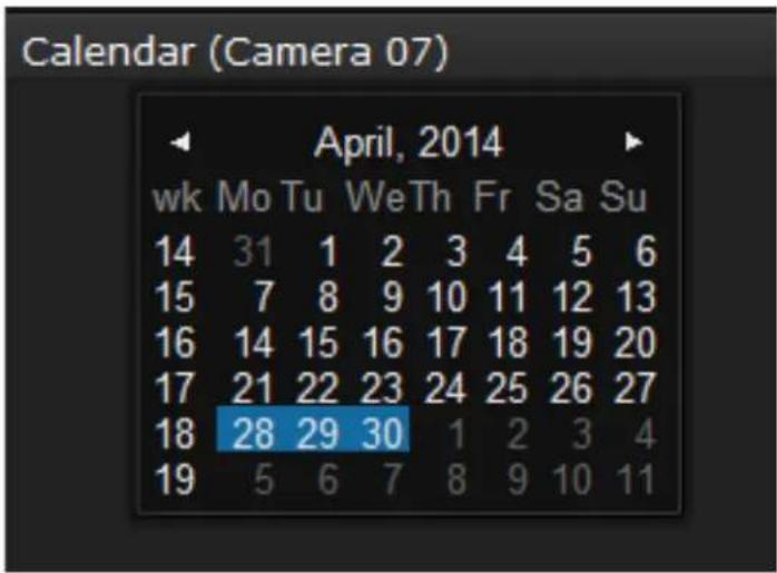
You may use the arrow button to view the records in other months. If there are no recordings in the current month, the recordings taken in the days of the following month will be shown steady.
Chapter Five System Settings
Since revision 2.0.0.x, the System Settings pages are made identical to those on the local console. Since the Setting pages are identical, the following pages will be omitted. Please refer to page 87 for the description of System Settings via a local console.
Some minor differences between the web console and local console exist. One is the Restore Factory default function. It is only available on the web console.
The restore function is not available on the local console, for users can use the reset button to perform the system default restoration.
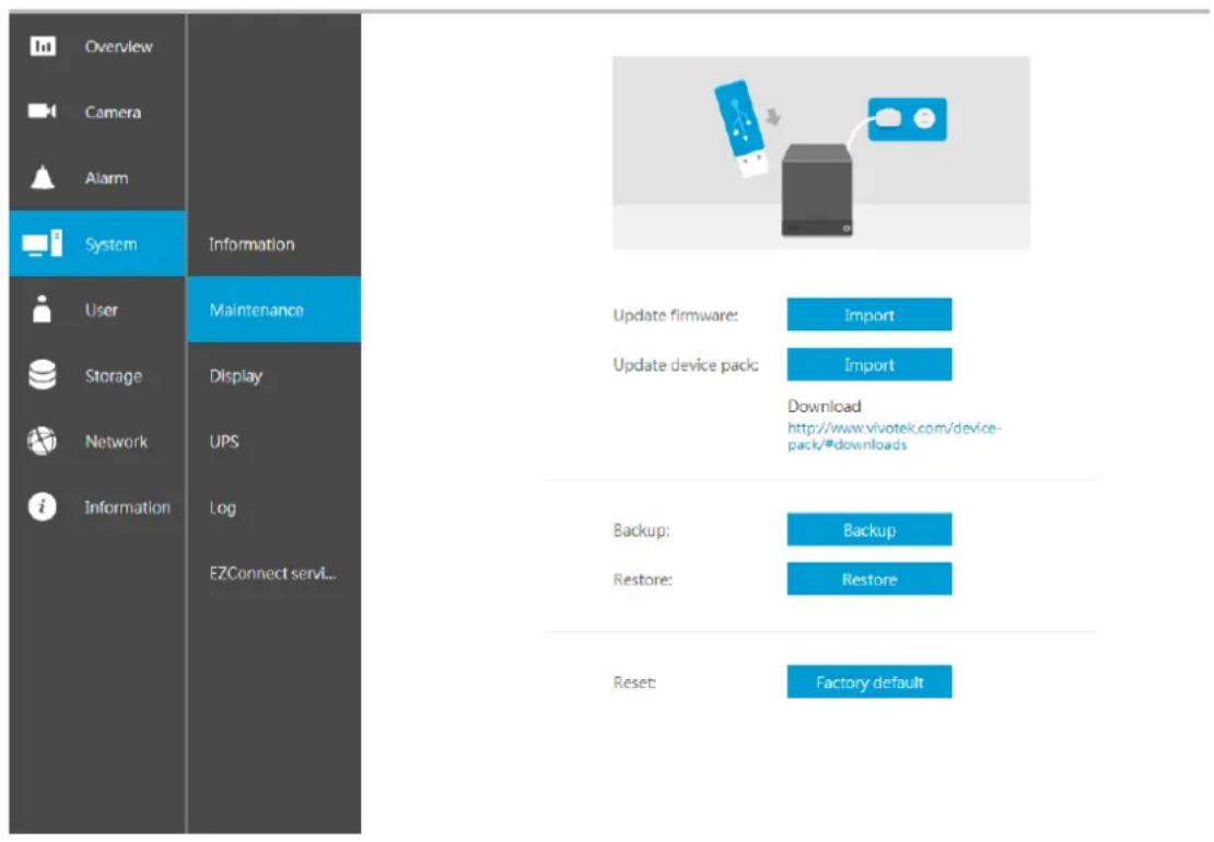
Another difference is the ability to enter a camera or system name using languages other than English. The NVR's system name also supports the use of other lanaguages. This is only achievable through a web console.
The following characters are not supported:
[>] [<][])[(]["][%][;][#][&][+][-][]

Chapter Six Operation

IMPORTANT:
- Before operating the NVR, make sure you have properly installed hard drives and configured the storage volumes. Otherwise, you will not be able to operate most of the system's functionality.
- Since the NVR system comes with 32-bit plug-ins for screen control, if your PC runs a default 64-bit IE browser and you manually enter the NVR's address on the browser, your browser session may malfunction. Instead, if you double-click on the discovered NVR on the IW2 or Shepherd utility, a 32-bit IE browser will open.
6-1. Liveview
6-1-1. Placing Cameras into the Layout
Legends and definitions of icons on the layout panel have been described on page 88.
It is presumed that you have properly inserted all network cameras in your deployment as previously described on page 88. All 8 cameras should be listed on the Camera list.
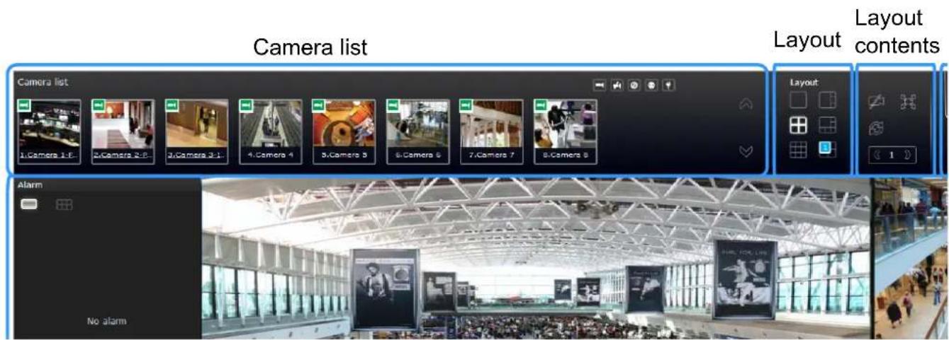
Note that layout design can only be performed by the system administrator.
To begin the design of your layout,
- Select a layout pattern by a single click. The options are: 1x1, 2x2, 3x3, 4x4, 1P+3, 1M+5, 1M+12, and 1M+31, where 4x4 and 1M+12 are available for the 16-CH model.
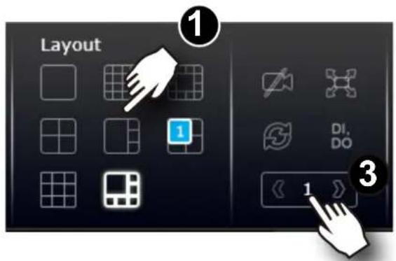
- Click and drag cameras from the Camera list to empty cells on your layout. Repeat the action until you placed all your cameras into the layout. You may also double-click on a camera's thumbnail to fill it into the first unoccupied view cell.
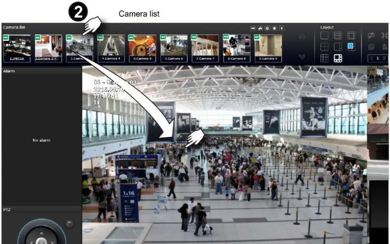
-
When you filled up the current layout, e.g., 6 camera into the 1M+5 layout, click the page switch to continue on the next layout page.
-
On completion, click Save to preserve your setting.
Placing different regional views of a fisheye camera into view cells will look like this:
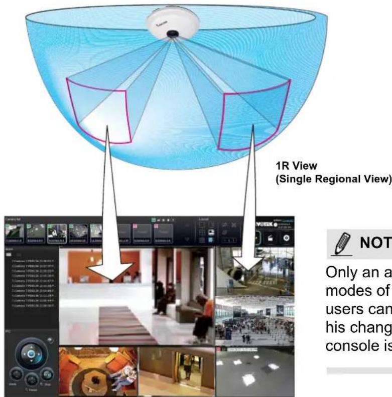

NOTE:
Only an administrator can alter the display modes of fisheye cameras. Although ordinary users can make changes to a regional view, his changes will not be preserved after a console is re-started.
In addition to fisheye cameras, if a camera has a wide field of view, you may also display its different fields of view in multiple view cells. Some view cells may also contain a PiP view that is digitally zoomed.
The fisheye mode button is available on the view cell where you inserted a fisheye camera. When a regional view is displayed, the shooting angle and image orientation is kept with the layout. See page 163 to see more about fisheye viewing modes.
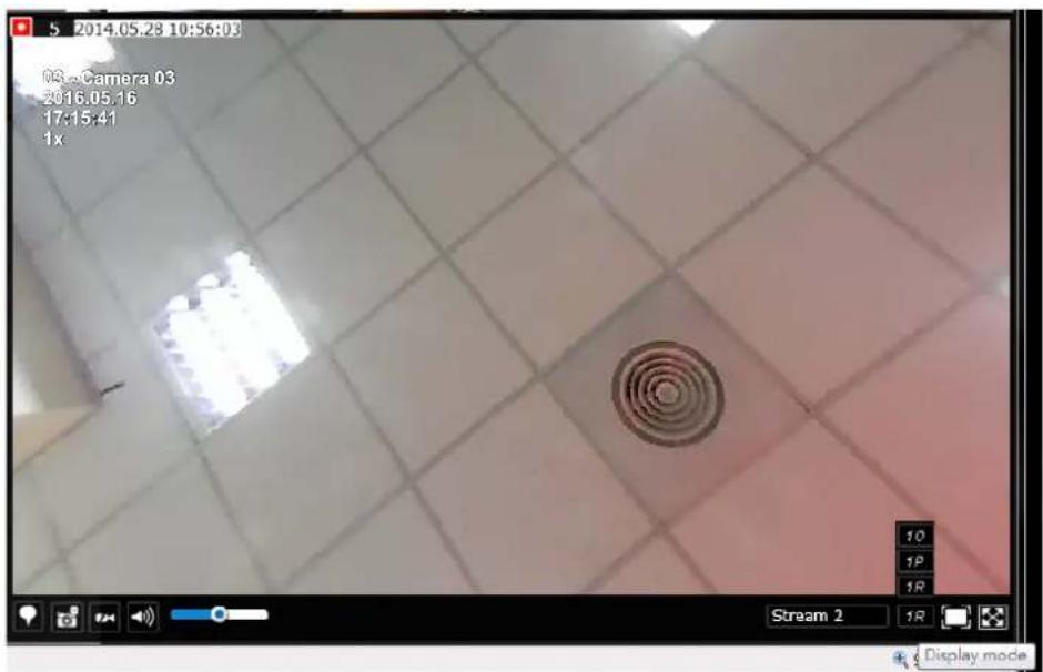
- When you are done with the current layout design, i.e., the user layout 1, click Save to preserve your settings. This message prompts on the screen whenever any change is made to the current layout.
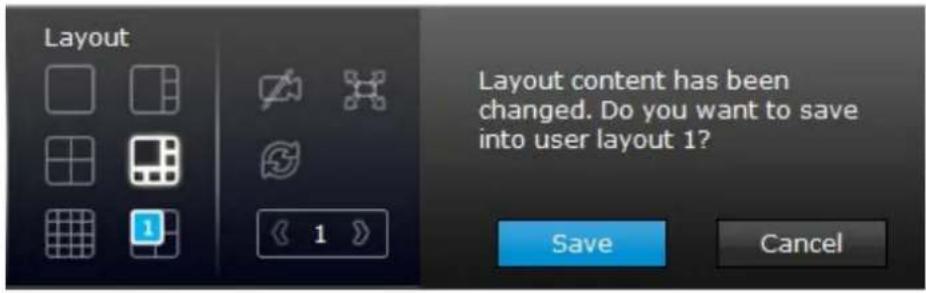
- You can create more user layouts by mouse-overing the user layout button. You may create more user layouts for different purposes, such as for the use of different users, or playing different views of a camera on multiple view cells.
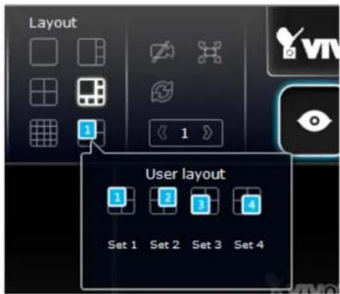
If users were created and some cameras are excluded from their access, a user may log in and see the locked-on cells as shown below:
A user who has limited access rights may still re-arrange the layout of view cells. However, his configuration change will not be saved after he leaves the current console.

NOTE:
By default, every users or administrator logs in to the Live view window to the last layout page he visited. The last layout page a user visited during the previous console becomes the default layout.
6-1-2. PTZ and Other Screen Controls
Note that the PTZ control panel only applies when you select a view cell with a camera that comes with mechanical PTZ functions. Currently the e-PTZ function is not supported by the NVR system.
With a PTZ camera, the buttons on the PTZ panel become functional when you mouse over its GUI elements. For all compatible cameras and exerting Zoom, Focus, and Patrol functions, please refer to page 165 for details. The Zoom function, for example, requires a camera that comes with a motorized zoom module, and may not be applicable to every PTZ camera.
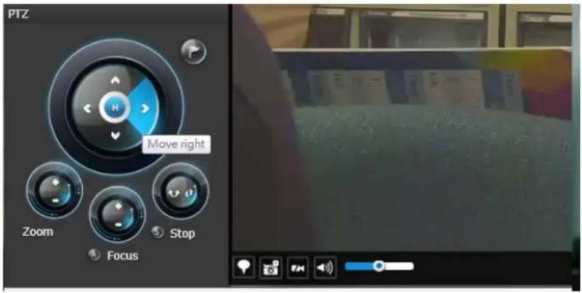
The preset positions and the patrol functions require the associated configuration on the cameras via a web console. Before you make use of these functions, you should set up the preset positions on a web console with the camera. The NVR GUI does not provide the configuration options with PTZ preset positions.
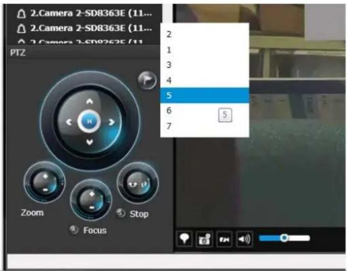
You can use Preset button to display preset positions and tell the camera to move and point at the preset direction, and to perform a camera tour to visit these positions in a consecutive order.
To access live view control,
- Click on a view cell. The view cell will become a focused view cell. The streaming control buttons will be listed at the bottom of a view cell. These buttons have been discussed on page 159.
- The 2nd click on a view cell enlarges it to the full of the live view area. The 3rd click reduces its size to the original focused view.
- To deselect a view cell, you can click on another view cell in the display area or click on the Restore button.
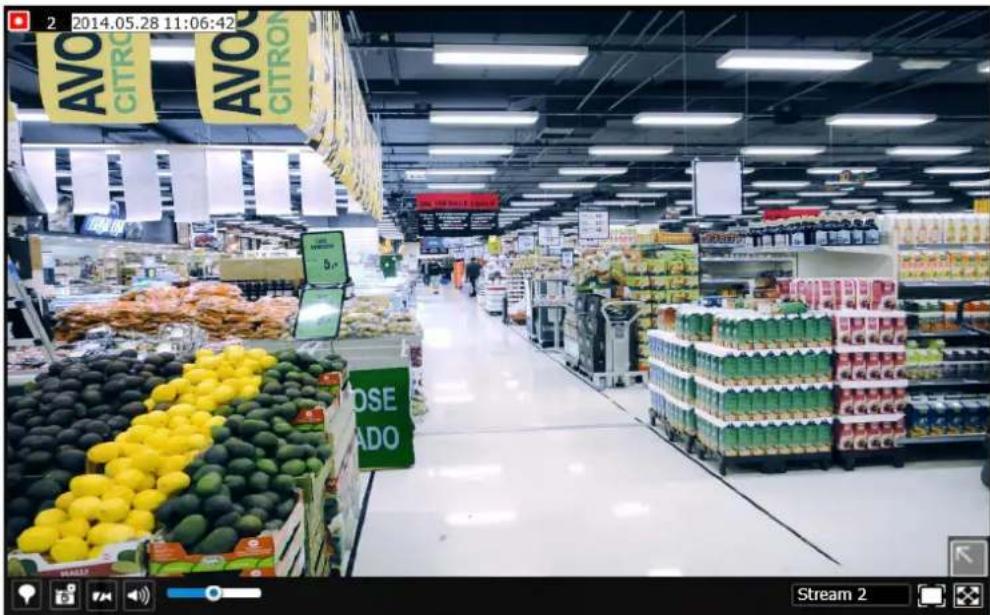
A selected, focused, view cell.

NOTE:
If you have concerns with the display quality and frame rate per second, refer to page 97 for how to configure video feeds for live viewing as well as for video recording. The configuration options can be found in Settings > Camera > Video.
Note that the constant bit rate methodology is applied in this system and it sets an upper threshold on the size of IP packets sent with the video streams. Image quality will be slightly compromised if reaching the ceiling of allowable bandwidth.
To place bookmarks and exert screen controls,
On a focused view cell, you can place a bookmark that saves a short description and a one-minute footage from the current feed. The bookmark is also displayed along with the recorded video, and therefore it is easier to look for a specific moment in time when you need to trace back for a scenario later.
The bookmark function can be executed on a live or recorded stream when you observe a situation from your Live view or Playback window. The precondition of using this function is that the video stream, while you are watching it on the view cell, must be recorded to the NVR at the same time.
To add a bookmark,
- Click on the button,
- Enter a short description that can be as long as 120 characters.
- Click on the + button or simply press Enter on your keyboard.
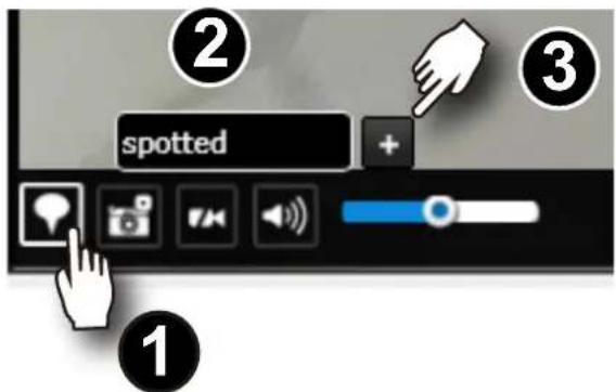
To Activate and Deactivate PiP function,
PiP is short for Picture in Picture, a function that provides digital zoom into a live video. When activated, a Global view window will appear at the lower right of the view cell as shown below. You can display only a portion of the complete video frame as an area of your interest. Using a click and drag on the ROI window, you can instantly move to other areas within the video frame.
You can resize the ROI window by a mouse hover on the lower-right corner of the window until the resize mark appears. The default size of the ROI window is 25% of the Global view. Click on the deactivate button to close the PiP window.
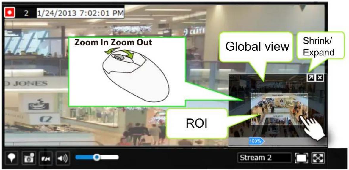
Note that not every camera supports the PiP function. For example, PTZ cameras do not support the PiP feature.
Refer to page 159 for GUI legends and individual functionality.
6-1-3. Audio
Audio is only transmitted through the camera in a view cell that is currently selected. You can manually tune the volume level, mute, or unmute the audio feed through a view cell.
6-1-4. Camera Properties and Controls
You can click on the underlined name entry of a camera on the camera list to open its properties window. Here you can find a short description of the camera name, address, and model name. You can also enable or disable the scheduled or continuous recording set for the camera. Click on their associated icons, √, 🔍 to change their recording status.
For a camera that is not performing a continuous recording, you can click on the Manual Recording button, √, to start a manual recording. The recording will stop using the same button. You can also manually turn on the digital output 📋e.g., to trigger an external alarm that is connected to a specific camera.
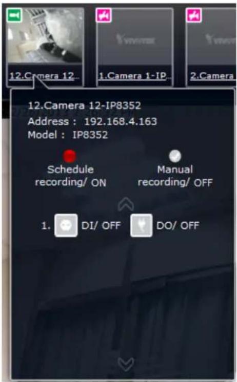
6-1-5. Alarm Panel
To receive alarms from cameras, you need to configure alarm triggers in the Settings > Alarm configuration window (see page 107). Network cameras' digital inputs, digital outputs, or motion detection can all be used to detect conditions in external environments. You can configure certain kind of actions to take place in response to the alarms: such as,
- recording the immediate image,
- sending an Email notification,
- sounding the onboard buzzer,
4, sending snapshots to an FTP server, - sending videos to a web server,
- moving camera lens to a preset location,
- triggering a camera's digital output.
The operation details of the Alarm panel and Alarm Playback utility have been described on page 167.
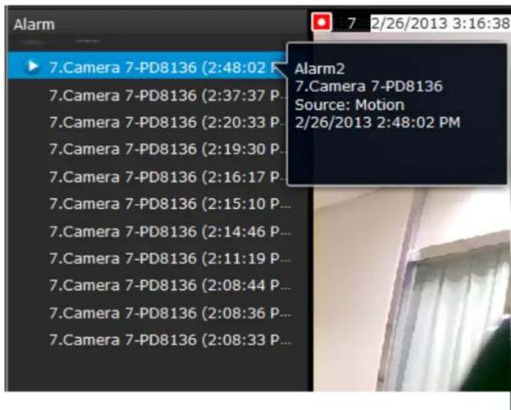
6-1-6. Layout view Control Buttons
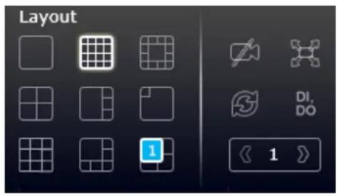
- When editing a user layout, you can use this button to clear all view cells of inserted cameras.
- This button extends the current layout to the full of the screen.
- The Rotate function lets system display successive pages in a user layout by the
A Rotate action 10 vilestop when layout page that does not contain camera views will be skipped.
- move to another page in the user layout,
- move to another user layout,
- click to select a view cell,
- remove a camera from view cell,
- click to disable the rotation function.
When your current layout spans across multiple pages, use the arrow buttons
switch from one page to another. The index number of the current page will be shown between the arrow buttons.
6-2. Search Recording Clips
The elements in the Camera list on a Search recording clips window are similar to those on a Liveview window. Please refer to page 152 for details on the Camera list panel.
However, on a Search recording clips window,
- You cannot click and drag a camera thumbnail to a playback view cell.
- A double-click on a camera does not display video in a view cell. A double-click displays a calendar where days with recorded videos are shown.
6-2-1. Begin Playback and Search for Past Recordings
- Select a layout. You can display the playback views of multiple cameras on one screen.
- Double-click on a camera.
- The Calendar panel will display the days video recording actually took place. And those days will be highlighted by a blue background (as the 25th and 28th in the screen below.)
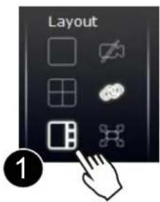
NOTE:
If a video stream was recorded in the MPEG-4 format, it will not be playable on the Playback window.
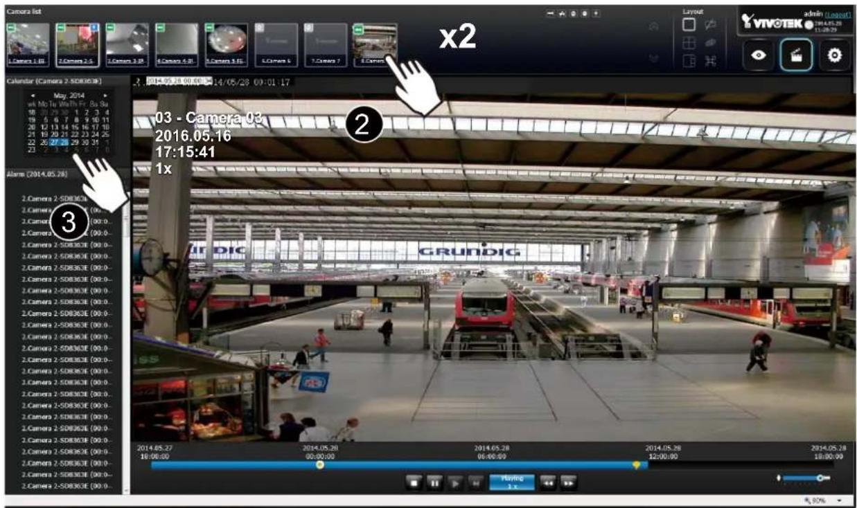
6-2-2. Past Alarms and Bookmarks
When you selected a day when alarms took place on a camera, the alarms will be listed on the Alarm panel. Up to 200 entries can be listed on a single page, and a max. of 1,000 entries across multiple pages.
You may then,
- Mouse over the alarm thumbnails and click on the play button. The Playback window will then play back the video recorded by the time of the occurrence.
- Unlike the Alarm playback function on the Liveview window, which only plays back the related video for only one minute, the alarm playback will continue throughout the recording of that day.
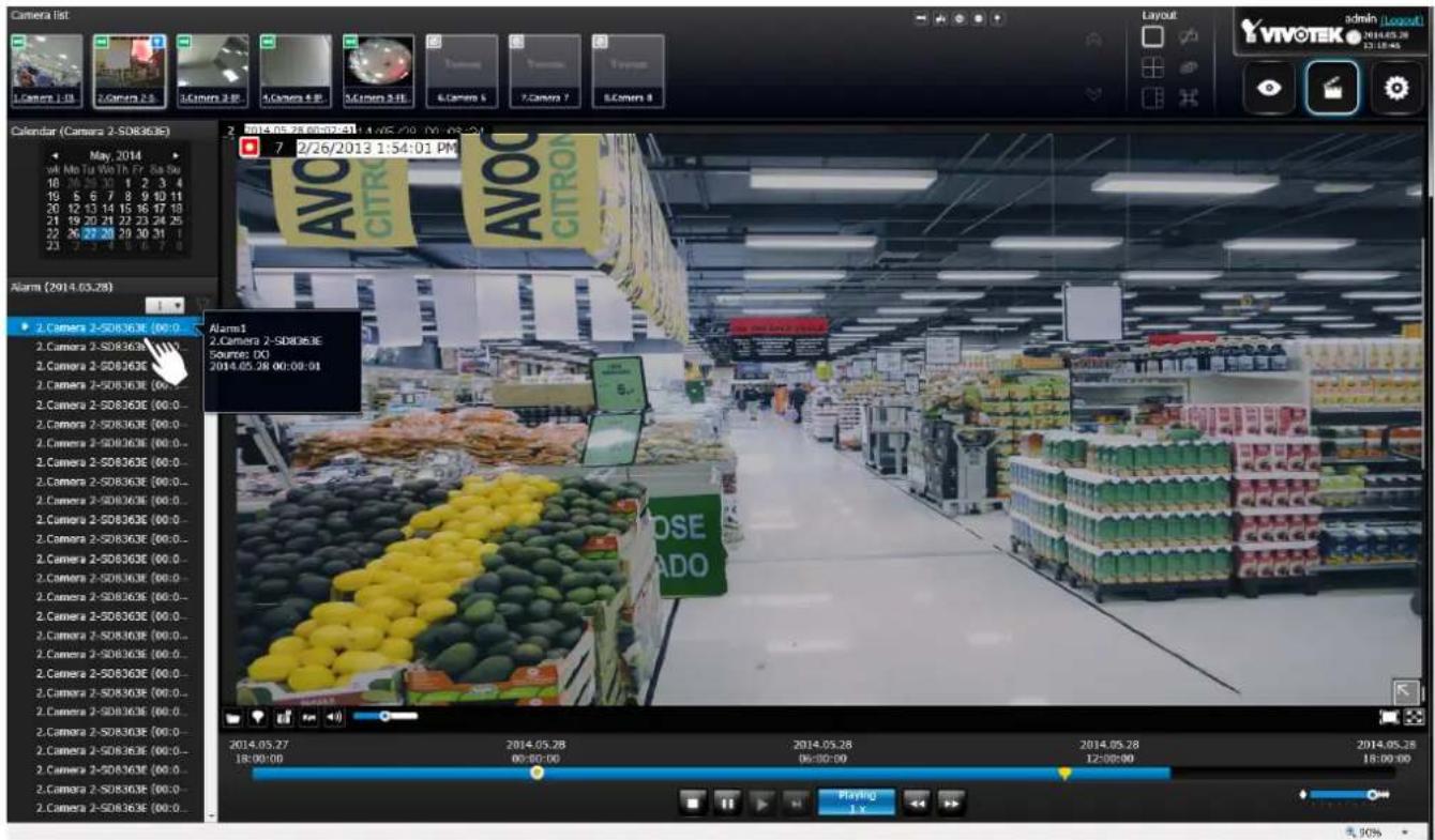
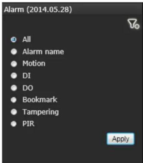
If you set up multiple triggering sources on a camera,
you can use the Alarm filter button to find the alarms of a specific type.
You can select the check circles to narrow down the types of listed alarms using search criteria by Alarm name, Motion, DI, DO, Bookmark, Tampering, or PIR.
Note that if searching by the Alarm name, the search does not apply to the camera model name that is automatically appended to the description of an alarm. Only the name of an alarm will apply in the search.
Note that the bookmarks you inserted on the Liveview window will be listed on the Alarm panel, and the bookmarks will also appear on the slide bar of the Playback window.
To retrieve or view the video clip tagged by the bookmark, click on it to play the video that was recorded by the time bookmark was inserted.
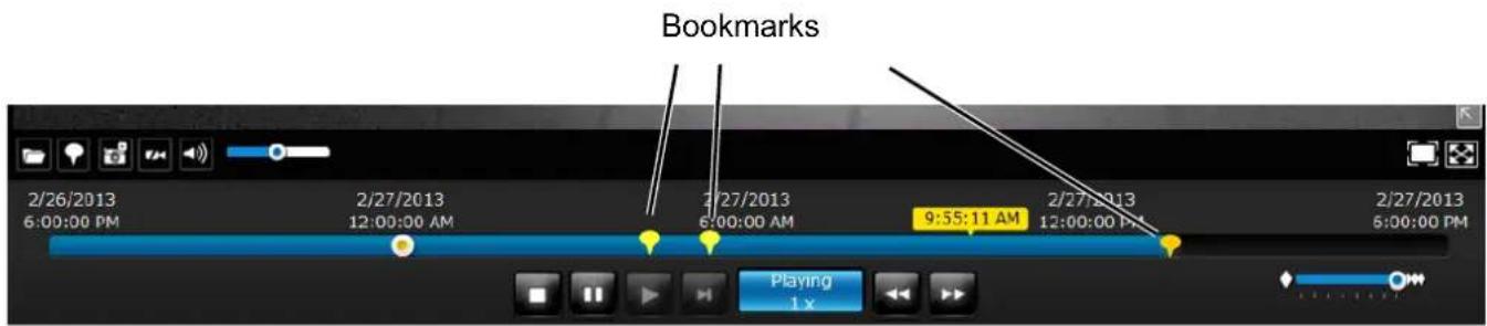
6-2-3. Synchronous Playback
The NVR supports synchronous playback, which allows you to review video clips from up to 4 cameras at the same time. These video clips will be retrieved simultaneously all playing for a specific point in time.
To perform synchronous playback:
- Select a layout from the Layout panel, e.g., a 2x2 layout.
- Click on the Synchronous playback button.
- Double-click to select a camera from the camera list. This camera becomes the Master camera.
- When the Calendar panel appears, click to select a date you prefer.
- Click and drag other cameras from the camera list to the empty view cells. These cameras will play back videos according to your operation on the Master camera.
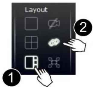
Note the following when using the Synchronous playback:
- Only the alarms triggered on the Master camera will be shown. In the Synchronous mode, you can not find the alarms or bookmarks generated for other cameras.
- The playback speed, selection of video clips, and alarm playback of all cameras are made synchronous.
6-2-4. Export media
To export video clips,
-
Click on the Export media button on the tool bar, while the Playback window is playing a video section of your interest.
-
An Export media window will prompt.
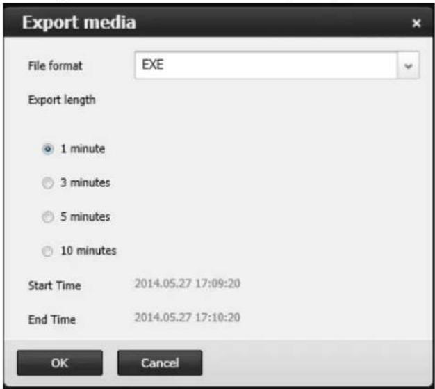
- Select the file format using the pull-down menu. An EXE file is an self-executable file playable by an embedded Media Player. The 3GP format is a multimedia container format for 3G UMTS services. These files can be played on QuickTime, RealPlayer, and VLC. The file name will look like this: [MAC]_ [DATE]_ [TIME]_ [CAMERA_INDEX].[3gp/exe].
- Select an export length of video by 1, 3, 5, or 10 minutes. The actual length can be longer due to the fact that the program needs to trace back to the previous I-frame for a complete rendering of video frames into the media.
- Click OK to proceed.
- System will prompt you for the EXE file. Click Save to proceed.

- The exported media file should be saved to the default download folder.
- A self-executable EXE file should look like this.
6-2-5. Time Search
Use the time line slide bar to find the nearest recording from a specific point in time.
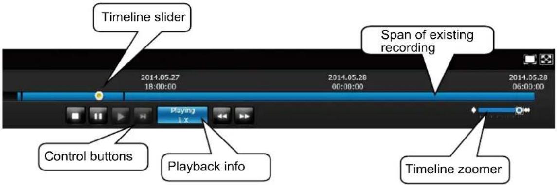
Details of the control bar in the Playback window can be found on page 175.

If the need arises to more accurately pin-point the occurrence of an event, you can use the Timeline zoomer and the slider thumb on the time line for a closer view into the existing recording.
| Timeline zoomer. Use the zoomer to zoom in for more precise skimming. | ||
| Timeline slider thumb. Click and drag this thumb button to move along and reach a specific point in time. | ||
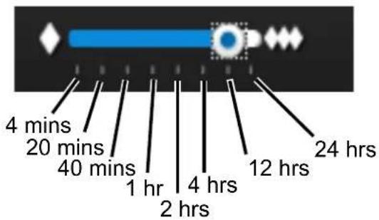
You can use the timeline zoomer to scale down the span of time. For example, if the time span is reduced to 1 hour, then each section on the time line represents 15 minutes of recording. The total time span on a timeline starts from the minimal of 4 minutes, 20 minutes, 40 minutes, 1 hour, and up to a maximum of 24 hours.
In the Synchronous play mode, a change to the zoomer will be reflected by all synchronously playing view cells.
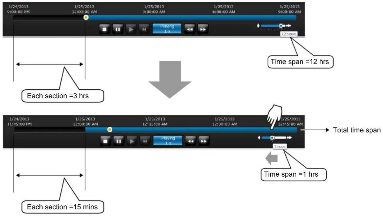
If recordings take place by an event-triggered recording, the intervals between recordings can be down to 1 minute, and the individual recordings will not be easily discernible. In this situation, you can mouse over the timeline to pin-point individual recording instances.
Safety and Compatibility

Federal Communications Commission (FCC) Statement
This Equipment has been tested and found to comply with the limits for a Class A digital device, pursuant to Part 15 of the FCC rules. These limits are designed to provide reasonable protection against harmful interference when the equipment is operated in a commercial environment. This equipment generates, uses and can radiate radio frequency energy and, if not installed and used in accordance with the instructions, may cause harmful interference to radio communications. Operation of this equipment in a residential area is likely to cause harmful interference in which case the user will be required to correct the interference at his own expense.
Warning:
[A shielded-type power cord is required in order to meet FCC emission limits and also to prevent interference to the nearby radio and television reception. It is essential that only the supplied power cord be used.]
[Use only shielded cables to connect I/O devices to this equipment.]
You are cautioned that changes or modifications not expressly approved by the party responsible for compliance could void your authority to operate the equipment.
[ ]: depend on EUT condition.

natural_image
Simple line drawing of a trash bin with crossed lines indicating no waste or plastic discharge (no text or symbols)Information on Disposal for Users of Waste Electrical & Electronic Equipment (private households)
This symbol on the products and/or accompanying documents means that used electrical and electronic products should not bemixed with general household waste.
For proper treatment, recovery and recycling, please take these products to designated collection points, where they will be accepted on a free of charge basis. Alternatively, in some countries you may be able to return your products to
your local retailerupon the purchase of an equivalent new product.
Disposing of this product correctly will help to save valuable resources and prevent any potential negative effects on humanhealth and the environment which could otherwise arise from inappropriate waste handling. Please contact your local authority for further details of your nearest designated collection point.
Penalties may be applicable for incorrect disposal of this waste, in accordance with national legislation.
For business users in the European Union
If you wish to discard electrical and electronic equipment, please contact your dealer or supplier for further information.
Information on Disposal in other Countries outside the European Union
This symbol is only valid in the European Union. If you wish to discard this product, please contact your local authorities or dealer and ask for the correct method of disposal.
Japan VCCI Class A statement
ACA (Australian Communications Authority)
CAUTION RISK OF EXPLOSION IF BATTERY IS REPLACED BY AN INCORRECT TYPE.
DISPOSE OF USED BATTERIES ACCORDING TO THE INSTRUCTIONS
Technology License Notice

HEVC Advance™
Covered by Patents at patentlist.hevcadvance.com
Notices from HEVC Advance:
THIS PRODUCT IS SOLD WITH A LIMITED LICENSE AND IS AUTHORIZED TO BE USED ONLY IN CONNECTION WITH HEVC CONTENT THAT MEETS EACH OF THE THREE FOLLOWING QUALIFICATIONS: (1) HEVC CONTENT ONLY FOR PERSONAL USE; (2) HEVC CONTENT THAT IS NOT OFFERED FOR SALE; AND (3) HEVC CONTENT THAT IS CREATED BY THE OWNER OF THE PRODUCT. THIS PRODUCT MAY NOT BE USED IN CONNECTION WITH HEVC ENCODED CONTENT CREATED BY A THIRD PARTY, WHICH THE USER HAS ORDERED OR PURCHASED FROM A THIRD PARTY, UNLESS THE USER IS SEPARATELY GRANTED RIGHTS TO USE THE PRODUCT WITH SUCH CONTENT BY A LICENSED SELLER OF THE CONTENT. YOUR USE OF THIS PRODUCT IN CONNECTION WITH HEVC ENCODED CONTENT IS DEEMED ACCEPTANCE OF THE LIMITED AUTHORITY TO USE AS NOTED ABOVE.
H.264
THIS PRODUCT IS LICENSED UNDER THE AVC PATENT PORTFOLIO LICENSE FOR THE PERSONAL AND NON-COMMERCIAL USE OF A CONSUMER TO (i) ENCODE VIDEO IN COMPLIANCE WITH THE AVC STANDARD ("AVC VIDEO") AND/OR (ii) DECODE AVC VIDEO THAT WAS ENCODED BY A CONSUMER ENGAGED IN A PERSONAL AND NON-COMMERCIAL ACTIVITY AND/OR WAS OBTAINED FROM A VIDEO PROVIDER LICENSED TO PROVIDE AVC VIDEO. NO LICENSE IS GRANTED OR SHALL BE IMPLIED FOR ANY OTHER USE. ADDITIONAL INFORMATION MAY BE OBTAINED FROM MPEG LA, L.L.C. SEE HTTP://WWW.MPEGLA.COM

- Table of Contents
- Chapter One Hardware Installation and Initial Configuration 7
- Chapter 1 Hardware ...... 10
- Section One Management over a Local Console 40
- Chapter Two Introduction to the Local Console Interface....40
- Chapter Three Configuration Using the Local Console 73
- WARNING:
- Revision History
- Symbols and Statements in this Document
- Read Before Use
- NOTE:
- Package Contents
- Chapter One Hardware Installation and Initial Configuration
- Introducing the Network Video Recorder
- Special Features
- Safety
- Installation Instructions
- Chapter 1 Hardware
- Interface Connectivity
- SIM card: Access from the Bottom
- Cabling Clearance
- Connector Pinouts-Front Panel
- Connector Pinouts-Rear Panel
- Terminal Block Connections
- IMPORTANT:
- RF Antenna Connector
- Installation
- Install a SIM card
- Install an LTE and Wi-Fi module
- Intall a 2.5" hard disk or SSD
- Initial Configuration—via a Local Console
- LED Indicators
- Power Up and Power Down
- Section One
- Management over a Local Console
- Chapter Two
- Introduction to the Local Console Interface
- 2-1. How to Begin
- How to access the Configuration Portal?
- How to access the Camera Portal?
- Tips:
- How to retrieve and access recorded videos?
- How to recieve system alarm?
- Why live view is unavailable?
- How do I move to another layout page?
- Why the onscreen tool bars disappear after some time?
- 2-2. Tracking and Viewing the Mobile NVR Videos on VAST2
- 2-2-1. Adding NVR as a VAST2 Sub-station
- 2-2-2. Configuring GPS and E-Map
- Double-Click the Google map icon.
- Alarm
- Camera triggers
- VAST server and NVR triggers
- 2-2-3. Playback Videos on the NVR H.D.D. from the VAST2 CMS Software
- 2-3. Operation on Camera View Cell
- 2-3-1. PTZ Panel
- 2-3-2. Digital zoom Panel
- 2-3-3. Play Recording Clips Panel
- 2-3-4. DI/DO
- 2-3-5. Others
- IMPPORTANT:
- 2-3-6. Right-click Commands
- Chapter Three
- Configuration Using the Local Console
- The Main Control Portal
- 3-1. Layout
- 3-2. DI/DO
- 3-3. Search recording clips
- 3-3-1. Time Search
- 3-3-2. Alarm Search
- 3-3-3. Storyboard
- hours/mins
- 3-4. Export recordings
- 3-5. Settings
- 3-5-1. Settings—Overview
- 3-5-2. Settings-Camera-Management
- To recruit cameras:
- Network
- Wi-Fi
- Camera position
- 3-5-3. Settings-Camera-Recording
- Recording options
- 3-5-4. Settings-Camera-Recording
- Recording Schedule
- 3-5-5. Settings-Camera-Media
- Stream management
- Video
- ■ Dynamic Intra frame period
- Audio
- 3-5-6. Settings-Camera-Image
- Display
- Image adjustment
- 3-5-7. Settings-Camera-Motion Detection
- Motion Detection
- 3-5-8. Settings-Camera-PTZ settings
- To configure a patrol:
- 3-5-9. Settings—Alarm—Alarm
- 3-5-10. Settings—Alarm—Email
- 3-5-11. Settings–System–Information
- 3-5-12. Settings—System—Maintenance
- 3-5-13. Settings—System—Display
- 3-5-14. Settings—System—PoE management
- 3-5-15. Settings—System—Power management
- 3-5-16. Settings—System—UPS
- 3-5-17. Settings-System-Log
- 3-5-18. Settings-User
- 3-5-19. Settings—Storage
- Disk Information:
- Verify:
- 3-5-20. Settings-Network
- Settings-Network-IP
- Prerequisites for Using 4G LTE:
- Ethernet Configuration:
- Settings-DDNS
- Settings–Service
- VAST2 auto connection
- NAT-traversal with OpenVPN
- 3-6. Devices
- GPS & G-sensor
- GPS
- G-sensor
- 3-7. Information
- NV9411P
- Section Two
- Management over a Web Console
- Chapter Four Login and Getting Started
- 4-1. Login
- Remember me:
- Login options:
- 4-2. Graphical Layout and Screen Elements—Liveview
- 4-2-1. Camera List Panel
- Camera Thumbnail:
- Sorting criteria
- 4-2-2. Layout
- User Layouts
- 4-2-3. Layout contents
- 4-2-4. Logo & Menu
- 4-2-5. View Cell panel
- Adding Cameras to View Cells
- Information Bar
- Tool Bar Functions in Details
- Play and Pause buttons:
- Bookmark:
- Snapshot:
- Clear:
- Mute and Unmute:
- Restore:
- Maximize:
- Activate and Deactivate PiP function:
- Volume controller:
- Fisheye display modes:
- (Original view)
- 1P (Panoramic view)
- 4-2-6. PTZ panel
- 4-2-7. Alarm panel
- Incoming Alarms
- 4-3. Graphical Layout and Screen Elements—Search recording clips
- 4-3-1. Camera List Panel
- 4-3-2. Search Recording Clips Layout
- 4-3-3. Logo & Menu
- 4-3-4. View Cells in Search Recording Clips
- Search Recording Clips Control Panel
- 4-3-5. Alarm Panel
- Alarm filter:
- 4-3-6. Calendar Panel
- Chapter Five System Settings
- Chapter Six Operation
- 6-1. Liveview
- 6-1-1. Placing Cameras into the Layout
- 6-1-2. PTZ and Other Screen Controls
- To access live view control,
- To place bookmarks and exert screen controls,
- To Activate and Deactivate PiP function,
- 6-1-3. Audio
- 6-1-4. Camera Properties and Controls
- 6-1-5. Alarm Panel
- 6-1-6. Layout view Control Buttons
- 6-2. Search Recording Clips
- 6-2-1. Begin Playback and Search for Past Recordings
- 6-2-2. Past Alarms and Bookmarks
- 6-2-3. Synchronous Playback
- 6-2-4. Export media
- 6-2-5. Time Search
- Safety and Compatibility
- Information on Disposal for Users of Waste Electrical & Electronic Equipment (private households)
- For business users in the European Union
- Information on Disposal in other Countries outside the European Union
- Japan VCCI Class A statement
- ACA (Australian Communications Authority)
- CAUTION RISK OF EXPLOSION IF BATTERY IS REPLACED BY AN INCORRECT TYPE.
- DISPOSE OF USED BATTERIES ACCORDING TO THE INSTRUCTIONS
- Technology License Notice
- Notices from HEVC Advance:
- H.264
Brand : Vivotek
Model : NV9311P
Category : Video recorder