
1977 - Professional audio equipment DRAWMER - Free user manual and instructions
Find the device manual for free 1977 DRAWMER in PDF.


| Product Type | Channel Strip (Mic Preamp, 3-Band EQ, Compressor, Saturation) |
| Dimensions | 482 mm (W) x 88 mm (H) x 270 mm (D) |
| Weight | 4.2 kg |
| Power Requirements | 230V or 115V AC, 50/60 Hz, 30 VA |
| Fuse Rating | 230V: T250mA, 115V: T500mA (20mm x 5mm, IEC 127-2) |
| Inputs | Mic (XLR), Line (XLR), Instrument (1/4" TS), Side Chain Insert (1/4" TRS) |
| Outputs | Main Output (XLR), Preamp Direct Out (XLR) |
| Mic Preamp Gain | 0 to +66 dB (Mic), -24 to +42 dB (Line/Instrument) |
| Mic Impedance | 200 Ω, 600 Ω, 2.4 kΩ (switchable) |
| Phantom Power | +48V DC (switchable) |
| High-Pass Filter | Variable 16 Hz - 130 Hz, 12 dB/octave |
| Equalizer | 3-band fully parametric: Low (40-725 Hz), Mid (140 Hz-13 kHz, variable bandwidth 0.25-2.75 octaves), High (530 Hz-20 kHz); +/-12 dB cut/boost; selectable slopes (Low: 6/9/12 dB/oct or Peak; High: 6/12 dB/oct) |
| Compressor | Threshold -40 to +20 dB, Ratio 1:1 to 10:1, Attack 0.2-100 ms, Release 0.05-2 s, PGM adaptive release, Big & Air modes |
| Saturation | Variable level (0-10), 3 types with low/high cut filters |
| Output Controls | Wet/Dry Mix, Fade (-∞ to +12 dB), VU Meter with +10 dB pad, Preamp Direct bypass |
| Signal Flow | Switchable EQ>Comp or Comp>EQ order |
| Construction | Steel chassis, aluminium front panel, 2U rack mount |
| Warranty | 1 year limited (repair/replacement at Drawmer's discretion) |
Frequently Asked Questions - 1977 DRAWMER
User questions about 1977 DRAWMER
0 question about this device. Answer the ones you know or ask your own.
Ask a new question about this device
Download the instructions for your Professional audio equipment in PDF format for free! Find your manual 1977 - DRAWMER and take your electronic device back in hand. On this page are published all the documents necessary for the use of your device. 1977 by DRAWMER.
USER MANUAL 1977 DRAWMER
Safety Consideration 2
Chapter 1 - Introduction
Introduction 3
Installation 4
Power Connection 4
Audio Connections 5
Chapter 2 - Control Description
Control Description 6
Chapter 3 - General Information
If a fault develops 10
Contacting Drawmer 10
Specification Data....10
Block Diagram 11
Recall Sheet 12
COPYRIGHT
This manual is copyrighted © 2023 by Drawmer Electronics Ltd. With all rights reserved. Under copyright laws, no part of this publication may be reproduced, transmitted, stored in a retrieval system or translated into any language in any form by any means, mechanical, optical, electronic, recording, or otherwise, without the written permission of Drawmer Electronics Ltd.
ONE YEAR LIMITED WARRANTY
Drawmer Electronics Ltd., warrants the Drawmer 1977 Channel Strip to conform substantially to the specifications of this manual for a period of one year from the original date of purchase when used in accordance with the specifications detailed in this manual. In the case of a valid warranty claim, your sole and exclusive remedy and Drawmer's entire liability under any theory of liability will be to, at Drawmer's discretion, repair or replace the product without charge, or, if not possible, to refund the purchase price to you. This warranty is not transferable. It applies only to the original purchaser of the product.
For warranty service please call your local Drawmer dealer. Alternatively call Drawmer Electronics Ltd. at +44 (0)1709 527574. Then ship the defective product, with transportation and insurance charges prepaid, to Drawmer Electronics Ltd., Coleman Street, Parkgate, Rotherham, S62 6EL UK. Write the RA number in large letters in a prominent position on the shipping box. Enclose your name, address, telephone number, copy of the original sales invoice and a detailed description of the problem. Drawmer will not accept responsibility for loss or damage during transit.
This warranty is void if the product has been damaged by misuse, modification or unauthorised repair.
THIS WARRANTY IS IN LIEU OF ALL WARRANTIES, WHETHER ORAL OR WRITTEN, EXPRESSED, IMPLIED OR STATUTORY. DRAWMER MAKES NO OTHER WARRANTY EITHER EXPRESS OR IMPLIED, INCLUDING, WITHOUT LIMITATION, ANY IMPLIED WARRANTIES OF MERCHANTABILITY, FITNESS FOR A PARTICULAR PURPOSE, OR NON-INFRINGEMENT. PURCHASER'S SOLE AND EXCLUSIVE REMEDY UNDER THIS WARRANTY SHALL BE REPAIR OR REPLACEMENT AS SPECIFIED HEREIN.
IN NO EVENT WILL DRAWMER ELECTRONICS LTD. BE LIABLE FOR ANY DIRECT, INDIRECT, SPECIAL, INCIDENTAL OR CONSEQUENTIAL DAMAGES RESULTING FROM ANY DEFECT IN THE PRODUCT, INCLUDING LOST PROFITS, DAMAGE TO PROPERTY, AND, TO THE EXTENT PERMITTED BY LAW, DAMAGE FOR PERSONAL INJURY, EVEN IF DRAWMER HAS BEEN ADVISED OF THE POSSIBILITY OF SUCH DAMAGES.
Some states and specific countries do not allow the exclusion of implied warranties or limitations on how long an implied warranty may last, so the above limitations may not apply to you. This warranty gives you specific legal rights. You may have additional rights that vary from state to state, and country to country.
DRAWMER
1977
Channel Strip
SAFETY CONSIDERATIONS
CAUTION - MAINS FUSE
TO REDUCE THE RISK OF FIRE
REPLACE THE MAINS FUSE ONLY WITH
A FUSE THAT CONFORMS TO IEC127-2.
250 VOLT WORKING, TIME DELAY TYPE
AND BODY SIZE OF 20mm x 5mm.
THE MAINS INPUT FUSE MUST BE
RATED AT 230V=T250mA and 115V=T500mA.
CAUTION - MAINS CABLE
DO NOT ATTEMPT TO CHANGE
OR TAMPER WITH THE
SUPPLIED MAINS CABLE.
CAUTION - SERVICING
DO NOT PERFORM ANY SERVICING.
REFER ALL SERVICING TO QUALIFIED
SERVICE PERSONNEL.
WARNING
TO REDUCE THE RISK OF FIRE OR
ELECTRIC SHOCK DO NOT EXPOSE
THIS EQUIPMENT TO RAIN OR MOISTURE.

CAUTION
RISK OF ELECTRIC SHOCK

In the interests of product development, Drawmer reserve the right to modify or improve specifications of this product at any time, without prior notice.
DRAWMER 1977
CHANNEL STRIP

INTRODUCTION
If you're looking to add vintage characteristics and analogue musicality to your recordings then look no further than the 1977, Drawmer's most comprehensive channel strip to date.
The 1977 gives you the clarity of an ultra clean preamplifier the precision of the three band parametric equaliser, the silkiness of the soft knee compressor and added to this the ability to dial in as much warmth as you desire via the 3 types of variable harmonic saturation.
The pristine preamplifier not only incorporates mic, line and instrument D.I. with 66dB of stepped gain, allowing you to make ultra clean, transparent and precise recordings, sweeten up dull audio or perfect your guitar sound, but also mic matching via switched impedance that brings out the best of every mic in your studio. Whether high-end, ribbon or even your dullest mic you will be able to find it's sweet spot.
The 1977 incorporates a true ‘parametric’ equaliser, with three bands of fully variable frequency control and cut and boost of +/-12dB’s and, in addition, a fully variable bandwidth control of the mid band, making it incredibly versatile and capable of modifying everything from subtle fine tuning to tone sculpting problematic recordings, and, of course, anything in between.
A full featured compressor allows you to control the dynamics of your recordings and our trademark 'Big' and 'Air' modes help to preserve the very deep lows and enhance the sparkling highs that lesser compressor's remove. The compressor section also incorporates variable harmonic Saturation with a choice of 3 styles, that will allow you to warm up your recordings with complete precision.
The output section includes a wet/dry mix for parallel processing that allows you to easily dial in how much EQ and compression is used via a single knob, plus an output fade control to either add fade outs or to boost the level to match high end audio interface audio input levels, along with a large backlit VU meter for accurate monitoring. And finally, a Preamp Direct switch that bypasses the EQ compressor and Saturation completely to provide an ultra clean microphone output.
The result of all these features is a modern take on vintage gear that gives you an incredible degree of control over the clarity, tone and warmth of your recordings, helping you to capture perfect audio every time.
Features:
- A THAT Corporation ultra clean mic preamplifier with 66dB of gain with phantom power and switchable mic impedance for accurate mic matching
- Separate Line & Mic input XLR's and pro quality instrument DI input with through output. Plus an XLR for the dedicated ultra clean direct pre-amp output and also for the overall output.
- FETs can be bypassed altogether to provide ultra clean outputs.
- A variable high pass filter control removes any rumble and allows you to tighten up the bottom end
- Phase reverse.
- Vintage-style three band full parametric EQ which takes it's inspiration from 1970's-era analogue gear, with variable frequency, +/-12dB cut and boost and variable bandwidth. Switch able slopes plus low peak settings allows you to adjust the focus and also magnify the bottom and top ends.
- Compressor includes standard controls and also 'Big' and 'Air' Modes Help to preserve the very deep lows and enhance the sparkling highs.
- Rear panel Side-chain insert point provides even further control.
• 3 types of variable Saturation adds vintage warmth.
- The order of the EQ and Compressor can be swapped and also each can bypassed to allow for comparisons.
- Variable Wet/Dry Mix plus Output Gain knobs give a 'Parallel E.Q. and Compression' function without the need for external mixing devices, providing complete and effortless control over the amount of equalisation and compression used and output levels.
- A backlit Analogue V.U. Meter with Switch able +10dB Re-scale Mode.
• Time delay relays on the output for clean power up/down.
- Internal Low Hum Toroidal Linear Power Supply with Voltage Selector Switch.
- Classic Drawmer build quality with rugged steel chassis and aluminium front panel.
- Designed and Handmade by Drawmer in the UK.
INSTALLATION
The 1977 is designed for standard 19" rack mounting and occupies 2U of rack space. Fibre or plastic washers may be used to prevent the front panel becoming marked by the mounting bolts.
- Care should be taken in the choice of positioning. The unit should not be mounted where other equipment obstructs the normal air flow. The unit should not be situated near any heat source, such as a radiator, stove or a high power amplifier that would generate heat.
- The appliance should not be operated near any water or in a location where moisture might be present.
- Always connect the mains earth to the unit.
If the 1977 is to be continuously moved from one location to another, we suggest using additional support in the rack at the rear of the unit.
POWER CONNECTION
The unit will have been supplied with a power cable suitable for domestic power outlets in your country. For your own safety it is important that you use this cable. The unit should always be connected to the mains supply earth using this cable, and no other.
If for some reason the unit is to be used at a mains input operating voltage which is different to that as supplied, the following procedure must be carried out.
1: Disconnect the unit from the mains.
2: Remove the two screws holding the voltage selection cover-plate.
3: Remove the cover plate and slide the switch fully to its opposite end.
4: Rotate the cover plate one half turn (180 degrees) and refit the two screws.
5: Replace with a correctly rated fuse for the selected operation voltage in the IEC socket:
230V-T250mA and 115V-T500mA
6: Re-connect to mains power source.
Never disconnect the earth from the mains supply


AUDIO CONNECTIONS
The inputs and outputs are electronically balanced on conventionally wired XLRs (pin 1 screen, pin 2 hot, pin 3 cold and XLR shell is connected to chassis). The 1977 fully conforms to the EMC standards, if the unit is used where it may be exposed to high levels of disturbance such as found close to a TV or radio transmitter we suggest that the screen of the signal cable is connected to the chassis connection on the XLR type connector. The operating level is nominally +4dBu.
If ground loop problems are encountered, never disconnect the mains earth, but instead, try disconnecting the signal screen on one end of each of the cables connecting the outputs of the 1977 to the patchbay. If such measures are necessary, balanced operation is recommended.
The side-chain access points are unbalanced. The side chain feature on the 1977 is part of the compressor feedback stage and would normally be connected to a normalised or semi-normalised pair of patchbay contacts. This would allow the user to insert additional EQ for some de-essing, or frequency conscious compression. The intended use of the audio insert jacks would be to patch in EQ (eg Drawmer 1961, 1974), reverb or similar processing. Connection is via stereo 14 " jacks, the wiring convention being: ring is signal send, tip is signal return and sleeve ground.
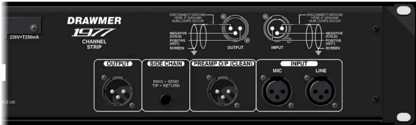
XLR - OUTPUT (MALE)
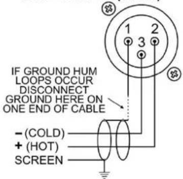
XLR - INPUT (FEMALE)
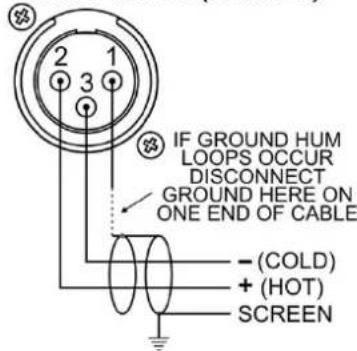
1/4" JACK - INSERT
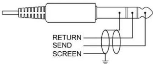
1/4"JACK - INSTRUMENT INPUT

CONTROL DESCRIPTION
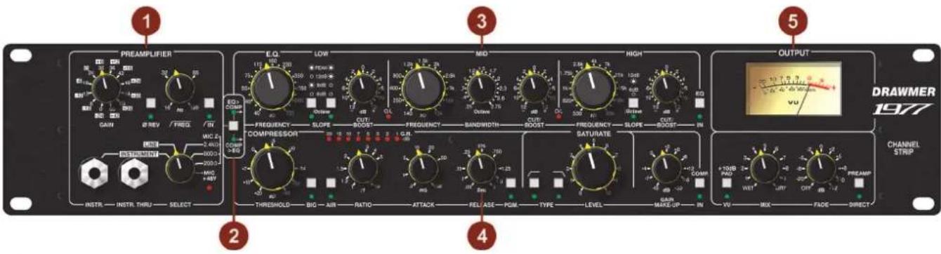
1 PREAMPLIFIER
Select
Mic +48V/Mic 200 Ohm/Mic 600 Ohm/Mic 2.4 kOhm/Line/Instrument
The source select is a six position rotary switch that, as well as setting the input source, also sets the load impedance of the microphone.
In the +48V Phantom Power switch position the red LED will illuminate to indicate that 48V of DC voltage is being sent down the XLR cable in order to power the electronics of a condenser microphone.
NOTE: DO NOT ACTIVATE THE +48V SETTING UNLESS THE MICROPHONE REQUIRES IT.
The switch can also provide three settings of load impedance in order to aid the matching for a dynamic microphone, at settings of 200, 600 and 2.4k Ohms.
In addition the same switch sets the source to Instrument (via the front panel instrument DI section) and Line (via the dedicated input on the rear panel).
Instrument Input
A 1/4" jack provides a specialised instrument input stage suitable for use with both active and passive guitar pickup systems as well as with electronic keyboards. A convenient Instrument Through 1/4" jack is also provided allowing the instrument signal to be routed elsewhere for alternative processing.
Gain
0 - +66dB (Mic) or -24 - +42dB (Instrument)
A twelve position preamplifier switch adds gain in 6dB steps from 0dB to +66dB in Mic mode, making it incredibly easy to replicate previous settings and have total control over levels.
Note that when the Instrument and Line is selected as the source they have an automatic 24dB pad and so a gain range of -24 to +42dB is achievable via this switch, as shown by the highlighted graticule markings.
Phase Reverse Off - On
This switch reverses the signal polarity, and is often useful when recording an instrument with more than one microphone. If, for example, you record a guitar cabinet with two mics, the two signals could be so similar that they would cancel each other out partially, resulting in a very thin sound. Reversing the phase of one channel would rectify this.
High Pass Filter
Variable Frequency 16Hz - 130Hz
The signal path incorporates a variable high-pass filter (also known as Low Cut), whose frequency is fully variable between 16Hz and 130Hz and at a slope of 12dB per Octave, and is used to attenuate low frequency signals that might otherwise prove troublesome, eg. traffic rumble or stage vibration, and let the higher frequencies pass.
Switch
Off - On
The high pass filter can be bypassed in order to hear A/B comparisons.
2 E.Q.>Comp / Comp>E.Q.
Select Off-On
The 1977 has very comprehensive Equaliser and Compressor stages that follow the Gain stage. This switch allows the signal path to either route the signal as Gain-Equaliser-Compressor-Output or alternatively route it as Gain-Compressor-Equaliser-Output, as each creates a distinctly different tonal quality, and coloration depending on the setting and allows the engineer to operate the 1977 to their own personal taste. As a very general rule, using EQ in front of your compressor produces a warmer tone, while using EQ after your compressor produces a cleaner sound, though this will depend on a number of factors.

E.Q.
LOW BAND
Frequency: 40Hz - 725Hz
This continually variable control sets the centre frequency where the signal is boost/cut. As it's completely variable it allows you to sweep the signal to pin point problematic frequencies providing greater flexibility and accuracy than lesser equalisers.
Slope: 6dB / 9dB / 12dB / PEAK
Sets by how much or 'fast' the signal is attenuated in dB's per octave at the Low frequencies. For example, a 6dB per octave Low slope located at 100Hz would accomplish 6dB of attenuation at 50Hz, and 12dB at 25Hz and so on until the signal is fully attenuated. 6dB per octave is more gentle and therefore more musical than 12dB, however, at 12dB per octave the signal is 'focused' but attenuation more noticeable.
The Peak setting adds a narrow bell shaped boost to the 12dB per octave low band filter at the knee frequency just before it rolls off. Especially useful on kick drums, it magnifies and gives extra weight to the hit whilst still filtering out any subsonic junk.
Cut/Boost: -12dB - +12dB
The amount of gain (boost) or reduction (cut) that is applied at the frequencies set within the band. The control is nonlinear and so is capable of subtle adjustments for mastering or larger variations for tone shaping.
MID BAND
Frequency: 140Hz - 13kHz
See Low Band Frequency
Bandwidth: 0.25 - 2.75 Octaves
Bandwidth is defined as the range of frequencies (width) centred around that set by the frequency knob allowing you to attenuate or boost a very narrow or wide range of frequencies within each EQ band.
On the 1977 the width of the effected signal is measured as Bandwidth (as opposed to 'Q', which it is inversely related to) and on the Mid band is fully parametric (as opposed to semi, quasi or fixed that you may find on other eq's) meaning that the bandwidths are fully adjustable across their entire range, providing greater control.
Cut/Boost: -12dB - +12dB
See Low Band Cut/Boost
HIGH BAND
Frequency: 530Hz - 20kHz
See Low Band Frequency
Slope: 6dB / 12dB
Sets by how much or ‘fast’ the signal is attenuated in dB’s per octave at the High frequencies. 6dB per octave is more gentle and therefore more musical than 12dB, however, at 12dB per octave the signal is ‘focused’ but attenuation more noticeable.
Cut/Boost: -12dB - +12dB
See Low Band Cut/Boost
Overload LED's
Inbetween each E.Q. band is an overload LED that illuminates to indicate that the E.Q. section has too much overall gain in total and one, or a combination of the three cut/boost controls should be reduced.
E.Q. Switch Off - On
A fully hard-wired bybass switch toggles the E.Q. section to be active or not, and is best used for A/B comparisons, or to remove the E.Q. stage from the signal path altogether.
4 COMPRESSOR
Threshold -40.0dB - +20dB
Determines the input level above which gain reduction will be applied. Soft knee compression takes place for signals exceeding the threshold level by a few decibels, above which level conventional 'ratio' compression is applied.
Big Switch Off - On
Big, when on, reduces the side-chain's sensitivity to low frequencies, with the result that less gain reduction is applied at those frequencies, creating the effect that the bass is louder or 'bigger'. The 'BIG' mode enables application in buss compression situations where you still want thick and warm tone yet complete dynamics control.
Air Switch Off - On
Air is used to re-introduce high frequencies, which can sometimes be lost after heavy compression, so that it sounds more intimate, detailed and transparent, but without making it sound harsh or introducing any noticeably unnatural artefacts. Cymbals are more vibrant without becoming splashy, and vocals sound more open but without becoming sibilant.
Ratio 1:1 - 10:1
Ratio determines the amount of compression (attenuation) to be used once the 'soft-knee' region is exceeded. If the ratio is set to 5:1 a signal exceeding the threshold by 5dB will be attenuated down to 1dB above the threshold, and likewise, a signal exceeding the threshold by 15dB will be attenuated down to 3dB above it. A ratio of 1:1 provides no compression, 4:1 is moderate, 8:1 strong, whilst 10:1 would be seen as approaching limiting.
Attack 0.2mS - 100mS
Sets the rate at which the compressor will respond to input signals that exceed the threshold level.
Release 0.05S - 2S
Sets the time taken for the signal to return to normal after the input level has fallen below threshold.
PGM Switch Off - On
When on causes the release times to vary in a manner which automatically adapts to the dynamics of the incoming signal.
Gain Reduction Meter 1, 2, 3, 5, 7, 10, 15, 20 -dB
An eight segment LED bargraph meter continuously monitors the gain reduction applied by the compressor and gives an indication of the amount of gain required to bring the signal back to its input level after it has been compressed.
SATURATE
Level 0 - 10
Sets the amount of Saturation applied to the signal, from very subtle, through to warm and to overdriven.
Type Switches
With both switches inactive the Saturation control operates throughout the entire frequency range. However, this can produce unwanted harshness in the low frequencies and excessive sibilance in the high frequencies.
Off - On
When active cuts the low frequencies prior to the saturation stage. This reduces the harshness of the saturation in the low frequencies, giving a warmer sound rather than over distortion to the bass.
Off - On
When active cuts the high frequencies after the saturation stage. This reduces the harshness of the saturation in the high frequencies, with the effect of far less sibilance than may otherwise occur.
The combination of variable Saturation plus the Type switches provide absolute control over the amount of distortion used and allows the engineer to apply either very subtle saturation or to really drive the saturation whilst still having control over the harshness that may occur.
Make Up Gain -10 - +20dB
During compression the signal is attenuated, gain may be required to produce the required output level. The amount of gain required in order to bring the signal level to the same is at input is displayed on the G.R. meter.
Comp. Switch Off - On
A fully hard-wired bypass switch toggles the Compressor section to be active or not, and is best used for A/B comparisons, or to remove the compressor stage from the signal path altogether.
5 OUTPUT VU Meter
A backlit moving coil VU meters monitor the level of the output signal.
+10dB Pad VU - +10dB
Adjusts the meters to show either normal output level, (and for those working at 'hot' output levels) VU +10dB i.e. with the switch at VU +10dB, when the VU meter reads 0dB the actual level is +10dB.
Mix Wet / Dry
A variable control that mixes a user defined amount of ‘uncompressed’ signal (dry) with the compressed signal (wet) to create a ‘parallel compression effect’ without the need for external mixing devices. In this way the amount of overall compression on the signal is under complete control.
Fade Off - +12dB
After E.Q. and compression gain may be required to produce the required output level. Adjust so that the output signal approaches the desired level only on signal peaks. Alternatively the control can be used to turn the output level off.
Preamp Direct Off - On
A fully balanced hard-wire bypass connects the preamplifier directly to the output without passing through the E.Q., the compressor FET's, the mix and gain controls at all. Use this to provide an ultra clean microphone signal or to hear the effects of the E.Q. and compressor in an A/B comparison.
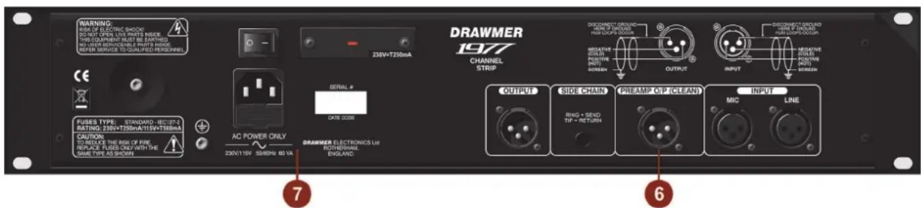
6 REAR CONNECTIONS
In addition to the instrument jack connectors located in the instrument section on the front panel there are also: Line Input
A dedicated line level input via balanced XLR is located on the rear panel.
Mic Input
A dedicated microphone input via balanced XLR.
Preamp O/P Clean
A dedicated output via balanced XLR. The signal is derived directly from the preamplifier and does not pass through the E.Q., compressor, saturation or output circuitry at all, providing an absolute clean signal.
Side Chain
The side chain connector is part of the compressor feedback stage and would normally be connected to a normalised or semi-normalised pair of patchbay contacts. This would allow the user to insert additional EQ for some de-essing, or frequency conscious compression. Connection is via an unbalanced stereo 14 " jack: ring is signal send, tip is signal return and sleeve ground.
Output
A dedicated output via balanced XLR.
7 POWER I.E.C./Power Switch/Voltage Selector Switch
See the Power Connection section of the manual
GENERAL INFORMATION
IF A FAULT DEVELOPS
For warranty service please call Drawmer Electronics Ltd. or their nearest authorised service facility, giving full details of the difficulty.
A list of all main dealers can be found on the Drawmer webpages.
On receipt of this information, service or shipping instructions will be forwarded to you.
No equipment should be returned under the warranty without prior consent from Drawmer or their authorised representative.
For service claims under the warranty agreement a service Returns Authorisation (RA) number will be issued.
Write this RA number in large letters in a prominent position on the shipping box. Enclose your name, address, telephone number, copy of the original sales invoice and a detailed description of the problem.
Authorised returns should be prepaid and must be insured.
All Drawmer products are packaged in specially designed containers for protection. If the unit is to be returned, the original container must be used. If this container is not available, then the equipment should be packaged in substantial shockproof material, capable of withstanding the handling for the transit.
CONTACTING DRAWMER
Drawmer Electronics Ltd., will be pleased to answer all application questions to enhance your usage of this equipment. Please address correspondence to:
Drawmer (Technical Help line)
Coleman Street
Parkgate
Rotherham
S62 6EL
UK
Alternatively contact us by E-mail on :
for sales enquiries: sales@drawmer.com
or for technical issues: tech@drawmer.com
Further information on all Drawmer dealers, Authorised service departments and other contact information can be obtained from our web pages on:
http://www.drawmer.com
1977 Channel Strip DATA SPECIFICATION
INPUT
Input Impedance 20k Ohms or greater
Maximum Input Level +21dBu
OUTPUT
Output Impedance 100 Ohms
Maximum Output Level +21dBu into 10k Ohms Load
FREQUENCY RESPONSE
20Hz to 20kHz +/-0.5dB
NOISE AT UNITY GAIN
20Hz - 20kHz >93dB
% DISTORTION (THD & NOISE) @ 1kHz Line Input with Compressor and EQ Engaged
0dB 0.01%
10dB 0.01%
MIC EIN -130dB
POWER REQUIREMENTS
230Volt or 115V at 50-60hZ, 30VA
FUSE RATING
T250mA for 230Volt,
T500mA for 115Volt
Conforming to IEC 127-2
FUSE TYPE
20mm x 5mm, Class 3 Timed-Blo, 250Volt working
CASE SIZE
482mm (W) x 88mm (H) x 270mm (D)
WEIGHT 4.2Kgs
BLOCK DIAGRAM


flowchart
graph TD
    A["AVIO OUTPUT"] --> B["BALANCED OUTPUT DRIVER"]
    B --> C["PREAMP DIRECT"]
    C --> D["OUTPUT GAIN"]
    D --> E["MIX"]
    E --> F["E.Q./COMPRESSOR ORDER PROCESSING"]
    F --> G["COMP IN"]
    G --> H["VCA"]
    H --> I["THRESHOLD"]
    I --> J["AIR"]
    J --> K["BIG"]
    K --> L["SATURATION"]
    L --> M["RELIEASE"]
    M --> N["RATIO"]
    N --> O["ATTACK"]
    O --> P["SIDE CHAIN"]
    P --> Q["EQ IN"]
    Q --> R["EQUALISER"]
    R --> S["CUT/BOOST"]
    S --> T["HIGH BAND"]
    T --> U["FREQUENCY"]
    U --> V["SLOPE"]
    V --> W["HIGH BAND"]
    W --> X["LID BAND"]
    X --> Y["FREQUENCY"]
    Y --> Z["LID BAND"]
    Z --> AA["FREQUENCY"]
    AA --> AB["LID BAND"]
    AB --> AC["FREQUENCY"]
    AC --> AD["LID BAND"]
    AD --> AE["FREQUENCY"]
    AE --> AF["LID BAND"]
    AF --> AG["FREQUENCY"]
    AG --> AH["LID BAND"]
    AH --> AI["FREQUENCY"]
    AI --> AJ["LID BAND"]
    AJ --> AK["FREQUENCY"]
    AK --> AL["LID BAND"]
    AL --> AM["FREQUENCY"]
    AM --> AN["LID BAND"]
    AN --> AO["FREQUENCY"]
    AO --> AP["LID BAND"]
    AP --> AQ["FREQUENCY"]
    AQ --> AR["LID BAND"]
    AR --> AS["FREQUENCY"]
    AS --> AT["LID BAND"]
    AT --> AU["FREQUENCY"]
    AU --> AV["LID BAND"]
    AV --> AW["FREQUENCY"]
    AW --> AX["LID BAND"]
    AX --> AY["FREQUENCY"]
    AY --> AZ["LID BAND"]
    AZ --> BA["FREQUENCY"]
    BA --> BB["LID BAND"]
    BB --> BC["FREQUENCY"]
    BC --> BD["LID BAND"]
    BD --> BE["FREQUENCY"]
    BE --> BF["LID BAND"]
    BF --> BG["FREQUENCY"]
    BG --> BH["LID BAND"]
    BH --> BI["FREQUENCY"]
    BI --> BJ["LID BAND"]
    BJ --> BK["FREQUENCY"]
    BK --> BL["LID BAND"]
    BL --> BM["FREQUENCY"]
    BM --> BN["LID BAND"]
    BN --> BO["FREQUENCY"]
    BO --> BP["LID BAND"]
    BP --> BQ["FREQUENCY"]
    BQ --> BR["LID BAND"]
    BR --> BS["FREQUENCY"]
    BS --> BT["LID BAND"]
    BT --> BU["FREQUENCY"]
    BU --> BV["LID BAND"]
    BV --> BW["FREQUENCY"]
    BW --> BX["LID BAND"]
    BX --> BY["FREQUENCY"]
    BY --> BZ["LID BAND"]
    BZ --> CA["FREQUENCY"]
    CA --> CB["LID BAND"]
    CB --> CC["FREQUENCY"]
1977 ver 01 A 23/05/23
| Session Recall | |
| 1977 Session No. | |
| Date | |
| Artist | |
| DRAWMER ELECTRONICS LTD ~ Coleman StreetRotherham ~ S. Yorkshire ~ UK© COPYRIGHT DRAWMER ELECTRONICS LTD 2022 | |
| Tape Location | |
DRAWMER
Session Recall
1261

flowchart
graph TD
    A["PREAMPUIFIER"] --> B["OUTPUT"]
    B --> C["SET/RESET"]
    C --> D["FINQUENCY"]
    D --> E["BANDWIDTH"]
    E --> F["FROQUENCY"]
    F --> G["SWITCH"]
    G --> H["SLOPE"]
    H --> I["COMPRESSOR"]
    I --> J["THRESHOLD"]
    J --> K["AIR"]
    K --> L["RATIO"]
    L --> M["ATTACK"]
    M --> N["RELEASE"]
    N --> O["PGM"]
    O --> P["TYPE"]
    P --> Q["LEVEL"]
    Q --> R["MAKE-UP"]
    R --> S["MAX-UP"]
    S --> T["MUX"]
    T --> U["FACE"]
    U --> V["MODE"]
    V --> W["OUT"]
    W --> X["PREMAP"]
    X --> Y["PREAMPUIFIER"]

    subgraph Control Components
        direction TB
        A --> A1["+10dB PAD 2-1"]
        A --> A2["3-7-10 dB 9-8-5-2-0-6-5-10"]
        A --> A3["COMPR PAD 1-1"]
        A --> A4["SET/RESET"]
        A4 --> A5["SET/RESET"]
        A5 --> A6["SET/RESET"]
        A6 --> A7["SET/RESET"]
        A7 --> A8["SET/RESET"]
        A8 --> A9["SET/RESET"]
        A9 --> A10["SET/RESET"]
        A10 --> A11["SET/RESET"]
        A11 --> A12["SET/RESET"]
        A12 --> A13["SET/RESET"]
        A13 --> A14["SET/RESET"]
        A14 --> A15["SET/RESET"]
        A15 --> A16["SET/RESET"]
        A16 --> A17["SET/RESET"]
        A17 --> A18["SET/RESET"]
        A18 --> A19["SET/RESET"]
        A19 --> A20["SET/RESET"]
        A20 --> A21["SET/RESET"]
        A21 --> A22["SET/RESET"]
        A22 --> A23["SET/RESET"]
        A23 --> A24["SET/RESET"]
        A24 --> A25["SET/RESET"]
        A25 --> A26["SET/RESET"]
        A26 --> A27["SET/RESET"]
        A27 --> A28["SET/RESET"]
        A28 --> A29["SET/RESET"]
        A29 --> A30["SET/RESET"]
        A30 --> A31["SET/RESET"]
        A31 --> A32["SET/RESET"]
        A32 --> A33["SET/RESET"]
        A33 --> A34["SET/RESET"]
        A34 --> A35["SET/RESET"]
        A35 --> A36["SET/RESET"]
        A36 --> A37["SET/RESET"]
        A37 --> A38["SET/RESET"]
        A38 --> A39["SET/RESET"]
        A39 --> A40["SET/RESET"]
        A40 --> A41["SET/RESET"]
        A41 --> A42["SET/RESET"]
        A42 --> A43["SET/RESET"]
        A43 --> A44["SET/RESET"]
        A44 --> A45["SET/RESET"]
        A45 --> A46["SET/RESET"]
        A46 --> A47["SET/RESET"]
        A47 --> A48["SET/RESET"]
        A48 --> A49["SET/RESET"]
        A49 --> A50["SET/RESET"]
        A50 --> E.O. LOW E.O. NET E.O. NET E.O. NET E.O. NET E.O. NET E.O. NET E.O. NET E.O. NET E.O. NET E.O. NET E.O. NET E.O. NET E.O. NET E.O. NET E.O. NET E.O. NET E.O. NET E.O. NET E.O. NET E.O. NET E.O. NET E.O. NET E.O. NET E.O. NET E.O. NET E.O. ENIINE
    end

    subgraph Control Components
        direction TB
        direction LR
        direction LR
        direction LR
        direction LR
        direction LR
        direction LR
        direction LR
        direction LR
        direction LR
        direction LR
        direction LR
        direction LR
        direction LR
        direction LR
        direction LR
        direction LR
        direction LR
        direction LR
        direction LR
        direction LR
        direction LR
        direction LR
        direction LR
        direction LR
        direction LR
        directionLR
    end

    subgraph Control Components
        direction TB
        direction LR
        direction LR
        direction LR
        direction LR
        direction LR
        direction LR
        direction LR
        direction LR
        direction LR
        direction LR
        direction LR
        direction LR
        direction LR
        direction LR
        direction LR
    end

    subgraph Control Components
        direction TB
        direction LR
        direction LR
        direction LR
        direction LR
        direction LR
        direction LR
        direction LR
        direction LR
        direction LR
        direction LR
        direction LR
        direction LR
        direction LR
      end

    subgraph Control Components
            direction TB
            direction LR
            direction LR
            direction LR
            direction LR
            direction LR
            direction LR
            direction LR
            direction LR
            direction LR
            direction LR
            direction LR
            direction LR
            direction LR
            direction LR
            direction LR
            direction LR
            direction LR
            direction LR
            direction LR
            direction LR
            direction LR
            direction LR
            direction LR
            direction LR
            direction LR
            directionLR
    end

    subgraph Control Components
            direction TB
            direction LR
            direction LR
            direction LR
            direction LR
            direction LR
            direction LR
            direction LR
            direction LR
            direction LR
            direction LR
            direction LR
            direction LR
            direction LR
            direction LR
            direction LR
            directionLR
    end

    subgraph Control Components
            direction TB
            direction LR
            direction LR
            direction LR
            direction LR
            direction LR
            directional LR
            directional LR
            directional LR
            directional LR
            directional LR
            directional LR
            directional LR
            directional LR
            directionalLR
    end

    subgraph Control Components
            direction TB
            direction LR
            direction LR
            direction LR
            direction LR
            direction LR
            directional LR
            directional LR
            directional LR
            directional LR
            directionalLR
    end

    subgraph Control Components
            direction TB
            direction LR
            direction LR
            direction LR
            direction LR
            directional LR
            directional LR
            directional LR
            directionalLR
    end

    subgraph Control Components
            direction TB
            direction LR
            direction LR
            direction LR
            direction LR
            directionalLR1,2,3,4,5,6,7,8,9,10,11,12,13,14,15,16,17,18,19,20,21,22,23,24,25,26,27,28,29,30,31,32,33,34,35,36,37,38,39,40,41,42,43,44,45,46,47,48,49,50,51,52,53,54,55,56,57,58,59,60,61,62,63,64,65,66,67,68,69,70,71,72,73,74,75,76,77,78,79,80,81,82,83,84,85,86,87,88,89,90,91,92,93,94,95,96,97,98,99,100|
    end

    subgraph Control Components (Output)
          direction TB1,B,C,D,E,F,G,H,J,K,L,M,N,O,P,Q,R,S,T,U,V,W,X,Y,Z,Z,Z,Z,Z,Z,Z,Z,Z,Z,Z,Z,Z,Z,Z,Z,Z,Z,Z,Z,Z,Z,Z,Z,Z,Z,Z,Z,Z,Z,Z,Z,Z,Z,Z,Z,Z,Z,Z,Z,Z,Z,Z,Z,Z,Z,Z,Z,Z,Z,Z,Z,Z,Z,Z,Z,Z,Z,Z,Z,Z,Z,Z,Z,Z,Z,Z,Z,Z,Z,Z,Z,Z,Z,Z,Z,Z,Z,Z,Z,Z,Z,Z,Z,Z,Z,Z,Z,Z,Z,Z,Z,Z,Z,Z,Z,Z,Z,Z,Z,z,Z,Z,Z,Z,Z,Z,Z,Z,Z,Z,Z,Z,Z,Z,Z,Z,Z,Z,Z,Z,Z,Z,Z,Z,Z,Z,Z,Z,Z,Z,Z,Z,Z,Z,Z,Z,Z,Z,Z,Z,Z,Z,Z,Z,Z,Z,Z,Z,Z,Z,Z,Z,Z,z,z,z,z,z,z,z,z,z,z,z,z,z,z,z,z,z,z,z,z,z,z,z,z,z,z,z,z,z,z,z,z,z,z,z,z,z,z,z,z,z,z,z,z,z,z,z,z,z,z,z,z,z,z,z,z,z,z,z,z,z,z,z,z,z,z,z,z,z,z,z,z,z,z,z,z,z,z,z,z,z,z,z,z,z,z,z,z,z,z,z,z,z,z,z,z,z,z,z,z-z,k,l,m,n,o,p,q,r,s,t,u,v,w,x,y,z,k,l,m,n,o,p,q,r,s,t,u,v,w,x,y,z,k,l,m,n,o,p,q,r,s,t,u,v,w,x,y,z,k,l,m,n,o,p,q,r,s,t,u,v,w,x,y,z,k,l,m,n,o,p,q,r,s,t,u,v,w,x,y,z,k,l,m,n,o,p,q,r,s,t,u,v,w,x,y,z,k,l,m,n,o,p,q,r,s,t,u,v,w,x,y,z,k,l,m,m,n,o,p,q,r,s,t,u,v,w,x,y,z,k,l,m,n,o,p,q,r,s,t,u,v,w,x,y,z,k,l,m,n,o,p,q,r,s,t,u,v,w,x,y,z,k,l,m,n,o,p,q,r,s,t,u,v,w,x,y,z,k,l,m,n,o,p,q,r,s,t,u,v,w,x,y,z,k,l,m,n,o,p,q,r,s,t,u,v,w,x,y,z,k,l,m,n,o,o,p,q,r,s,t,u,v,w,x,y,z,k,l,m,n,o,p,q,r,s,t,u,v,w,x,y,z,k,l,m,n,o,p,q,r,s,t,u,v,w,x,y,z,k,l,m,n,o,p,q,r,s,t,u,v,w,x,y,z,k,l,m,n,o,p,q,r,s,t,u,v,w,x,y,z,k,l,m,n,o,p,q,r,s,t,u,v,w,x,y,z,k,l,m,n,o,p,q,R,s,t,u,v,w,x,y,z,k,l,m,n,o,p,q,r,s,t,u,v,w,x,y,z,k,l,m,n,o,p,q,r,s,t,u,v,w,x,y,z,k,l,m,n,o,p,q,r,s,t,u,v,w,x,y,z,k,l,m,n,o,p,q,r,s,t,u,v,w,x,y,z,k,l,m,n,o,p,q,r,s,t,u,v,w,x,y,z,k,l,m,n,o,p,q,r,s,t,u-v,w,x,y,z,k,l,m,n,o,p,q,r,s,t,u,v,w,x,y,z,k,l,m,n,o,p,q,r,s,t,u,v,w,x,y,z,k,l,m,n,o,p,q,r,s,t,u,v,w,x,y,z,k,l,m,n,o,p,q,r,s,t,u,v,w,x,y,z,k,l,m,n,o,p,q,r,s,t,u,v,w,x,y,z,k,l,m,n,o,p,q,r,s,t,u,v,w,x,y-z,k,l,m,n,o,p,q,r,s,t,u,v,w,x,y-z,k,l,m,n,o,p,q,r,s,t,u,v,w,x,y-z,k,l,m,n,o,p,q,r,s,t,u,v,w,x,y-z,k,l,m,n,o,p,q,r,s,t,u,v,w,x,y-z,k,l,m,n,o,p,q,r,s,t,u,v,w,x,y-z,k,l,m,n,o,p,q,r,s,t,u,v,w,x,y-z,k,l,m n,o,p,q,r,s,t,u,v,w,x,y-z,k,l,m,n,o,p,q,r,s,t,u,v,w,x,y-z,k,l,m,n,o,p,q,r,s,t,u,v,w,x,y-z,k,l,m,n,o,p,q,r,s,t,u,v,w,x,y-z,k,l,m,n,o,p,q,r,s,t,u,v,w,x,y-z,k,l,m,n,o,p,q,r,s,t,u,v,w,x,y-z,k,l,m,n,o,p,q,R,s,t,u,v,w,x,y-z,k,l,m,n,o,p,q,r,s,t,u,v,w,x,y-z,k,l,m,n,o,p,q,r,s,t,u,v,w,x,y-z,k,l,m,n,o,p,q,R,s,t,u,v,w,x,y-z,k,l,m,n,o,p,q,r,s,t,u,v,w,x,y-z,k,l,m,n,o,p,q,R,s,t,u,v,w,x,y-z,k,l,m,n,o,p,q,r,s,t,u,v,w,x,y-z,k,l,m,n,o,p,q,R,s,t,u,v,w,x,y-z,k,l,m,n,o,p,q,R,s,t,u,v,w,x,y-z,k,l,m,n,o,p,q,R,s,t,u,v,w,x,y-z,k,l,m,n,o,p,q,R,s,t,u,v,w,x,y-z,k,l,m,n,o,p,q,R,s,t,u,v,w,x,y-z,k,l,m,n,o,p,q,R,s,t,u,v,w,x,y-z,k,l,m,n,o,p,q,R,s,t,u-v,w,x,y-z,k,l,m,n,o,p,q,R,s,t,u-v,w,x,y-z,k,l,m,n,o,p,q,R,s,t,u-v,w,x,y-z,k,l,m,n,o,p,q,R,s,t,u-v,w,x,y-z,k,l,m,n,o,p,q,R,s,t,u-v,w,x,y-z,k,l,m,n,o,p,q,R,s,t,u-v,w,x,y-z,k,l,m,n,o,p,q,R,s,t,u-v,w,x,y-Z,k,l,m,n,o,p,q,R,s,t,u-v,w,x-yz,k,l,m,n,o,p,q,R,s,t,u-v,w,x-yz,k,l,m,n,o,p,q,R,s,t,u-v,w,x-yz,k,l,m,n,o,p,q,R,s,t,u-v,w,x-yz,k,l,m,n,o,p,q,R,s,t,u-v,w,x-yz,k,l,m,n,o,p,q,R,s,t,u-v,w,x-yz,k,l,m,n,o,p,q,R,s,t,u-v,w,x-yz,k,l,m[niC=O+IeO+FeO+FEO/NINIC=MINIC=MINIC=MINIC=MINIC=MINIC=MINIC=MINIC=MINIC=MINIC=MINIC=MINIC=MINIC=MINIC=MINIC=MINIC=MINIC=MINIC=MINIC=MINIC=MINIC=MINIC=MINIC=MINIC=MINIC=MINIC=MINIC=MINIC=MINIC=MINIC=MINIC=MINIC=MINIC=MINIC=MINIENLINEINSTRUMENTINFIRENINSTRUMENTINFIRENINSTRUMENTINFIRENINSTRUMENTINFIRENINSTRUMENTINFIRENINSTRUMENTINFIRENINSTRUMENTINFIRENINSTRUMENTINFIRENINSTRUMENTINFIRENINSTRUMENTINFIRENINSTRUMENTINFIRENINSTRUMENTINFIRENINSTRUMENTINFIRENINSTRUMENTINFIRENINSTRUMENTINFIRENINSTRENGTHLINEINSTRUMENTINFIRENINSTRUMENTINFIRENINSTRUMENTINFIRENINSTRUMENTINFIRENINSTRUMENTINFIRENINSTRUMENTINFIRENINSTRUMENTINFIRENINSTRUMENTINFIRENINSTRUMENTINFIRENINSTRUMENTINFIRENINSTRUMENTINFIRENINSTRUMENTINFIRENINSTRUMENTINFIRENINSTRUMENTINFIRENINDIANIDIANIDIANIDIANIDIANIDIANIDIANIDIANIDIANIDIANIDIANIDIANIDIANIDIANIDIANIDIANIDIANIDIANIDIANIDIANIDIANIDIANIDIANIDIANIDIANIDIANIDIANIDIANIDIANIDIANIDIANIDIANIDIANIDIANIDIANIDIANIDIANIDIANIDIANIDIANIDIANIDIANIDIANIDIANIDIANIDIANIDIANIDIANIDIANIDIANIDIAN IDIANIDIANIDIANIDIANIDIANIDIANIDIANIDIANIDIANIDIANIDIANIDIANIDIANIDIANIDIANIDIANIDIANIDIANIDIANIDIANIDIANIDIANIDIANIDIANIDIANIDIANIDIANIDIANIDIANIDIANIDIANIDIANIDIANIDIANIDIANIDIANIDIANIDIANIDIANIDIANIDIANIDIANIDIANIDIANIDIANIDIANIDIANIDIANIDIANIDIANIDLINGLINEINSTRUMENTINFIRENINSTRUMENTINFIRENINSTRUMENTINFIRENINSTRUMENTINFIRENINSTRUMENTINFIRENINSTRUMENTINFIRENINSTRUMENTINFIRENINSTRUMENTINFIRENINSTRUMENTINFIRENINSTRUMENTINFIRENINSTRUMENTINFIRENINSTRUMENTINFIRENINSTRUMENTINFIRENINSTRUMENTINFIRENINFIRENINDIAIENDIAIENDIAIENDIAIENDIAIENDIAIENDIAIENDIAIENDIAIENDIAIENDIAIENDIAIENDIAIENDIAIENDIAIENDIAIENDIAIENDIAIENDIAIENDIAIENDIAIENDIAIENDIAIENDIAIENDIAIENDIAIENDIAIENDIAIENDIAIENDIAIENDIAIFINELINCEINESSIONAL
- COPYRIGHT
- ONE YEAR LIMITED WARRANTY
- DRAWMER
- 1977
- Channel Strip
- SAFETY CONSIDERATIONS
- CAUTION - MAINS FUSE
- DRAWMER 1977
- INTRODUCTION
- Features:
- INSTALLATION
- POWER CONNECTION
- AUDIO CONNECTIONS
- CONTROL DESCRIPTION
- PREAMPLIFIER
- Select
- Instrument Input
- Gain
- Phase Reverse Off - On
- High Pass Filter
- Variable Frequency 16Hz - 130Hz
- Switch
- E.Q.>Comp / Comp>E.Q.
- Select Off-On
- E.Q.
- LOW BAND
- MID BAND
- HIGH BAND
- Overload LED's
- E.Q. Switch Off - On
- COMPRESSOR
- SATURATE
- Type Switches
- Comp. Switch Off - On
- OUTPUT VU Meter
- REAR CONNECTIONS
- Mic Input
- Preamp O/P Clean
- Side Chain
- Output
- POWER I.E.C./Power Switch/Voltage Selector Switch
- GENERAL INFORMATION
- IF A FAULT DEVELOPS
- CONTACTING DRAWMER
- Channel Strip DATA SPECIFICATION
- Session Recall
- 1261
Brand : DRAWMER
Model : 1977
Category : Professional audio equipment