
89-481 - Système de drainage Biltema - Free user manual and instructions
Find the device manual for free 89-481 Biltema in PDF.


| Product Type | Roof Drainage System (Gutter Kit) |
| Brand | Biltema |
| Model | 89-481 |
| Material | Galvanized Steel |
| Color | Silver/Gray |
| Gutter Length | Up to 10 m per section (multiple sections joinable) |
| Gutter Slope | 3-5 mm per meter |
| Hook Spacing | 600 mm (60 cm) |
| End Hook Offset from Gutter End | Approx. 100 mm (10 cm) |
| Downpipe Diameter | Approx. 100 mm (4 inches) |
| Max Roof Length Without Additional Downpipe | 10 m |
| Components Included | Gutter hooks, gutter outlets, gutter ends, gutters, gutter joints, pipe bends, intermediate pipes, pipe wraps, water drainage fittings, adjustable gutter hooks |
| Tools Required | Folding rule, pencil, paper, hacksaw, pliers, screwdriver, sheet metal jointing compound, string, spirit level, rubber mallet |
| Installation Surface | Fascia board (wood, stone, or concrete) |
| Fastening Method | Screws for wood; screws and plugs for stone |
| Water Drainage Options | Underground drainage, ground drainage, or rainwater collection |
| Special Features | Adjustable gutter hook for angled fascia boards; fold-out shoe for water butt |
| Safety Notes | Never use angle grinder; use hacksaw only; ensure correct slope for water flow |
| Maintenance | Clean gutters regularly; check sealant integrity; replace damaged components |
| Repairability | Components are replaceable individually (gutter sections, hooks, joints) |
Frequently Asked Questions - 89-481 Biltema
User questions about 89-481 Biltema
0 question about this device. Answer the ones you know or ask your own.
Ask a new question about this device
Download the instructions for your Système de drainage in PDF format for free! Find your manual 89-481 - Biltema and take your electronic device back in hand. On this page are published all the documents necessary for the use of your device. 89-481 by Biltema.
USER MANUAL 89-481 Biltema
natural_image
Exploded view of black plastic pipe fittings and fixtures, showing structural components (no text or symbols)CE
TAKAVVATTNING
INNEHÅLL
- RÄNNKROK
- OMVIKNINGSKUPA
- RÄNNGAVEL
- HÄNGRÄNNA
- RÄNNSKARV
- RÖRVINKEL OCH MELLANSTYCKE
- RÖRSVEP
- VATTENAVLEDNING
- STÄLLBAR RÄNNKROK
INTRODUKTION
natural_image
Illustration of hands using a tool to cut a circular object with a diagonal line crossing (no text or symbols)natural_image
Simple line drawing of a ruler measuring a surface, no text or symbols presentBild B
natural_image
Diagram of a curved pipe or channel with directional arrows indicating flow or movement, no text or symbols presentBild E
Min. 30 mm
natural_image
Illustration of hands using a tool to cut or clamp a pipe (no text or symbols visible)Bild G

natural_image
Illustration of a mechanical clamp or tool interacting with a surface (no text or symbols)Bild H

natural_image
Illustration of a hand using a tool to cut a pipe with a dashed line indicating a measurement (no text or symbols present)Bild I

natural_image
Illustration of a hand holding a pipe fitting with a pointed tip (no text or symbols)Bild J
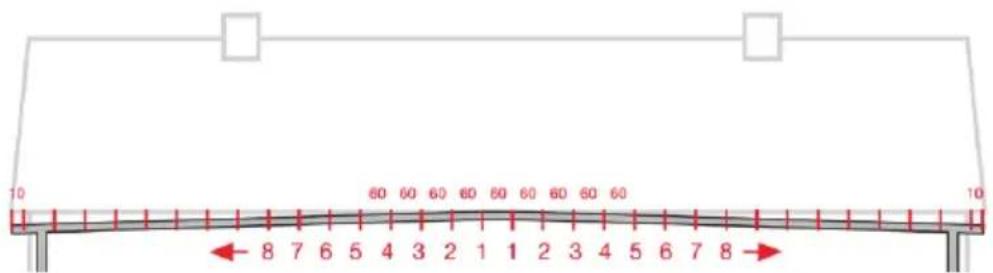
Bild F
3. RÄNNGAVEL
natural_image
Illustration of two hands holding a tool, one pointing at a surface and the other writing on a notepad (no text or symbols present)Bild K

natural_image
Illustration of a hand holding a rectangular object with a curved line extending from it (no text or symbols)Bild L
natural_image
Illustration of a hand holding a pen or stylus over a rolled document or scroll (no text or symbols visible)Bild M
4. HÄNGRÄNNA
natural_image
Illustration of hands holding a small object over a metal pipe (no text or symbols visible)Bild N
5. RÄNNSKARV
natural_image
Illustration of a hand holding a rifle with a pointed grip, labeled 'Bild 0' (no other text or symbols)6. RÖRVINKEL OCH MELLANSTYCKE
natural_image
Diagram of a pipe drainage system with a curved pipe and attached sink, labeled 'Bild P' (no text or symbols on the diagram itself)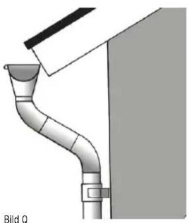
natural_image
Diagram of a pipe fitting with a label 'Bild Q' at the bottom (no other text or symbols)7. RÖRSVEP
natural_image
Illustration of a hand using a tool to adjust or install a cylindrical component (no text or symbols visible)Bild R

natural_image
Illustration of hands using a tool to adjust or install a mechanical component (no text or symbols visible)Bild S
8. VATTENAVLEDNING
Bild T

natural_image
Technical illustration of a pipe fitting with vertical supports (no text or symbols)Bild U
natural_image
Illustration of a pipe pouring liquid into a cylindrical container (no text or symbols)Bild V
9. STÄLLBAR RÄNNKROK
natural_image
3D rendered image of a curved mechanical component with internal slots and a central slot (no text or symbols)4

natural_image
Diagram of a curved pipe or channel with a dashed line and labeled point 'b' (no text or symbols beyond labels)2

natural_image
Illustration of hands using a tool to cut a rectangular object with a diagonal line (no text or symbols)natural_image
Simple line drawing of a ruler measuring a surface, no text or symbols presentBilde B
natural_image
Diagram of a curved pipe or channel with directional arrows indicating flow or movement, no text or symbols presentBilde E
natural_image
Illustration of hands using a tool to clamp or adjust a pipe fitting (no text or symbols visible)Bilde G

natural_image
Illustration of a hand gripping a tool against a surface (no text or symbols)Bilde H

natural_image
Illustration of a hand connecting a pipe with a dashed line indicating a measurement or angle (no text or symbols present)Bilde I

natural_image
Illustration of hands performing a manual valve or fitting operation (no text or symbols visible)Bilde J
Bilde F
3. ENDESTYKKE
Det er enklest å montere endestykket før du monterer takrennen. Legg en streng fugemasse for metall i takrennen (bilde K). Vri endestykket inn i takrennen, og skyv den inn cirka 15 mm fra enden av takrennen. Trykk deretter endestykket ned i takrennen, slik at baksiden av endestykket styres inn under bakkanten av takrennen. Slå deretter fast endestykket med hånden (bilde L), og fjern overfl ødig fugemasse. Kanten du ikke trenger, kan du brette bort (bilde M).

natural_image
Illustration of two hands holding a tool, one pointing at a surface (no text or symbols visible)Bilde K

natural_image
Illustration of a hand holding a flat object, no text or symbols presentBilde L

natural_image
Illustration of a hand holding a pen or stylus over a rolled document or scroll (no text or symbols visible)Bilde M
4. TAKRENNE
Legg rennen i kroken slik at baksiden ligger under den lille kanten på baksiden av kroken. Press takrennen ned i kroken, og fest den ved å brette krokens fremre blikk over kanten på takrennen (bilde N).

natural_image
Illustration of hands holding a small object over a metal pipe (no text or symbols visible)Bilde N
5. RENNESKJ∅T
natural_image
Illustration of hands holding a rifle with a scope, labeled 'Bilde 0' (no other text or symbols)6. R∅RVINKEL OG MELLOMSTYKKE
natural_image
Diagram of a bathroom sink with pipe fittings and a wall-mounted fixture (no text or symbols)
natural_image
Technical illustration of a pipe fitting with a sloped edge, labeled 'Bilde Q' (no other text or symbols)7. NEDL∅PSKLAMMER
natural_image
Hand holding a cylindrical container with a saw, no visible text or symbolsBilde R

natural_image
Illustration of hands using a tool to adjust or install a mechanical component (no text or symbols visible)Bilde S
8. DRENERING
natural_image
Technical diagram of a mechanical assembly with a cylindrical component and textured base (no text or symbols)Bilde T

natural_image
Technical illustration of a pipe fitting with vertical supports (no text or symbols)Bilde U

natural_image
Illustration of a pipe pouring liquid into a cylindrical container, with vertical supports and a bracket in the background (no text or symbols)Bilde V
9. JUSTERBAR RENNEKROK
natural_image
3D rendered image of a curved mechanical component with internal slots and a central slot (no text or symbols)
2

natural_image
Illustration of hands using a tool to cut a rectangular block with a cross mark (no text or symbols)natural_image
Simple line drawing of a ruler measuring a surface, no text or symbols presentKuva B
natural_image
Diagram of a curved pipe or channel with directional arrows indicating flow or movement, no text or symbols presentKuva E
natural_image
Illustration of hands using a tool to clamp or adjust a pipe fitting (no text or symbols visible)Kuva G

natural_image
Illustration of a hand using a tool to lift or lift a curved object (no text or symbols)Kuva H

natural_image
Illustration of a hand holding a pipe joint with dashed lines indicating a measurement or angle (no text or symbols present)Kuva I

natural_image
Illustration of hands performing a mechanical joint or fitting operation (no text or symbols visible)Kuva J

Kuva F
3. KOURUN PÄÄTYKAPPALE
natural_image
Illustration of two hands holding a tool, one pointing at a surface and the other cutting a piece (no text or symbols present)Kuva K
natural_image
Illustration of a hand holding a rolled document or scroll (no text or symbols visible)Kuva L

natural_image
Illustration of a hand holding a pen or tool over a rolled document (no text or symbols visible)Kuva M
4. RÄYSTÄSKOURU
natural_image
Illustration of hands holding a tool on a cylindrical object (no text or symbols visible)Kuva N
5. KOURULIITOS
natural_image
Illustration of hands holding a rifle with a scope, labeled 'Kuva 0' (no other text or symbols)6. KULMAPUTKI JA VÄLIKAPPALE
natural_image
Diagram of a curved pipe system with a valve and support bracket, labeled 'Kuva P' (no text or symbols on the diagram itself)
natural_image
Illustration of a pipe fitting with a handle, showing structural details (no text or symbols)7. SYÖKSYPUTKEN KIINNIKE
natural_image
Hand holding a cylindrical container with a tool, no visible text or symbolsKuva R

natural_image
Illustration of hands using a tool to adjust or install a mechanical component (no text or symbols visible)Kuva S
8. VEDEN POISTAMINEN
natural_image
Technical diagram of a mechanical assembly with a central pipe and textured base, labeled 'Kuva T' (no readable text or symbols beyond label)
natural_image
Technical illustration of a pipe fitting with vertical supports, labeled 'Kuva U' (no other text or symbols)
natural_image
Illustration of a funnel pouring liquid into a cylindrical tank, with no text or symbols present.9. SÄÄDETTÄVÄ KOURUKOUKKU
natural_image
3D rendered image of a curved mechanical component with internal slots and a central slot (no text or symbols)
2

natural_image
Illustration of hands using a power tool to cut a circular component with a diagonal line crossing (no text or symbols)OBS! Brug aldrig vinkelsliber.
1. RENDEJERN
natural_image
Simple line drawing of a ruler measuring a surface, no text or symbols presentFig. B
Fig. C
natural_image
Diagram of a curved pipe or channel with directional arrows indicating flow or movement, no text or symbols present.Fig. E
natural_image
Illustration of hands using a tool to clamp or adjust a pipe fitting (no text or symbols visible)Fig. G

natural_image
Illustration of a hand gripping a tool against a surface (no text or symbols)Fig. H

natural_image
Illustration of a hand holding a pipe joint with dashed lines indicating a measurement or angle (no text or symbols present)Fig. I
natural_image
Illustration of hands performing a mechanical joint or clamp operation (no text or symbols visible)Fig. J
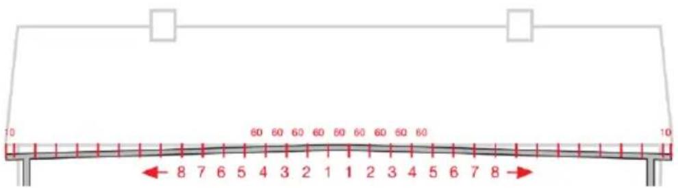
Fig. F
3. ENDEBUND
natural_image
Illustration of hands using a tool to cut or mark a surface, no text or symbols presentFig. K

natural_image
Illustration of hands holding a flat sheet of paper (no text or symbols visible)Fig. L

natural_image
Illustration of a hand holding a pen or stylus over a rolled document or scroll (no text or symbols visible)Fig. M
4. TAGRENDE
natural_image
Illustration of hands connecting a pipe with a small component (no text or symbols)Fig. N
5. SAMLESTYKKE
natural_image
Illustration of hands holding a rifle with a pointed tip, labeled 'Fig. 0' (no text or symbols on the diagram itself)Fig. 0
6. R∅RB∅JNING OG MELLEMSTYKKE
natural_image
Diagram of a pipe elbow joint with a curved pipe and support structure (no text or symbols)Fig. P
natural_image
Diagram of a pipe fitting with a bracket, showing structural details (no text or symbols)Fig. Q
7. R∅RHOLDER
natural_image
Hand holding a mechanical component with a tool, no visible text or symbolsFig. R

natural_image
Illustration of hands using a tool to adjust or install a mechanical component (no text or symbols visible)Fig. S
8. VANDAFLEDNING
natural_image
Technical diagram of a mechanical assembly with a cylindrical component and textured base (no text or symbols)Fig. T
natural_image
Technical illustration of a pipe fitting with vertical supports (no text or symbols)Fig. U

natural_image
Illustration of a pipe pouring liquid into a container, with vertical supports and a bracket (no text or symbols)Fig. V
9. JUSTERBART RENDEJERN
natural_image
3D rendered image of a curved mechanical component with internal slots and a central slot (no text or symbols)4
natural_image
Diagram of a curved pipe or channel with a dashed line and labeled dimension 'b' (no text or symbols beyond label)5
ROOF DRAINAGE
CONTENTS
- GUTTER HOOK
- GUTTER OUTLET
- GUTTER END
- GUTTER
- GUTTER JOINT
- PIPE BEND AND INTERMEDIATE PIPE
- PIPE WRAP
- WATER DRAINAGE
- ADJUSTABLE GUTTER HOOK
INTRODUCTION
This guide will help you mount our products quickly and easily. You will need the following tools and products: Folding rule, pencil, paper, hacksaw, pliers, screwdriver, sheet metal jointing compound, and possibly a string or a bending lever.
Take the time to read through the mounting instructions in full before starting the mounting work. Many steps can be carried out on the ground before mounting the components to the building.
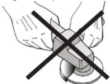
natural_image
Illustration of hands using a tool to cut a mechanical component (no text or symbols visible)NOTE! Never use an angle grinder.
1. GUTTER HOOK
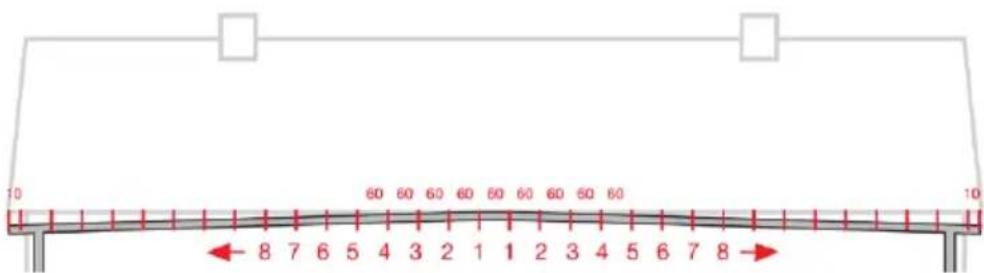
The gutter hooks holding the gutter are placed at 60 cm intervals on a slope. The first and the last hooks are fastened about 10 cm from the end of the gutter (Picture A).

Picture A
Gutter slope
The gutter should have a slope of 3-5 mm/m along the fascia board, provided that the fascia board is horizontal. Check this using a spirit level. If the fascia board is not horizontal, you must compensate for this when calculating the gutter slope. The gutter should slope towards the down pipe. The gutter hooks are bent in increasing lengths to achieve the correct slope of the gutter.

natural_image
Simple line drawing of a ruler measuring a surface, no text or symbols present(Picture B
Bending of gutter hooks
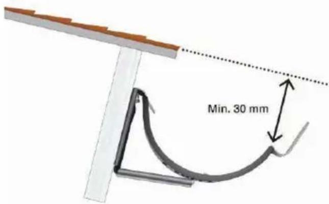
Before bending the first gutter hook you need to find out the roof pitch. Place a folding rule parallel to the roof and let it hang down vertically (Picture B). Copy the angle of the folding rule on a piece of paper and extend the line representing the roof (Picture C). Place a hook against the vertical line on the paper and position it so that the tip of the hook is 30 mm below the continuation of the roof line.

natural_image
Diagram of a micrometer measuring a curved wire with a ruler, showing measurement setup (no text or labels)Picture C
The point at which the extended roof line intersects with the hook is the first bending mark, known as Point 0 (Picture C).
Line-up the other hooks alongside the one marked with Point 0 and draw a horizontal line from the first to the last hook (Picture D). The bending point on the last hook should be 3-5 mm x gutter length in meters above the 0-point line (e.g. for an 8 m long gutter the bending point should be 24-40 mm above the 0-point line). Then draw a line from this point to
Point 0, which will indicate the correct bending point for each hook. It is best to use a special hook bender.

Picture D
Gutter hooks for fascia board
If the roof has a vertical fascia board the easiest way is to use a short or a compact hook which is fastened by screws on the fascia board (Picture E). If the fascia board is fixed at an angle you can use an adjustable gutter hook. See 9. Adjustable gutter hook.
Install the first hook so that the tip of the hook is at least 30 mm below the continuation of the roof line (Picture E). Fasten a piece of string at the gutter hook and fasten the other end of the string where the down pipe should be placed. Use a spirit level and make sure that the slope is 3-5 mm/m. Install the remaining hooks along the string.

natural_image
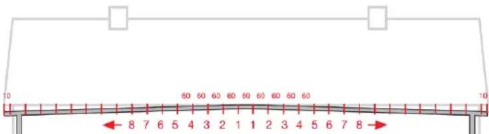
Diagram of a curved pipe or channel with directional arrows indicating flow or movement, no text or symbols presentPicture E If the roof is longer than 10 m you need one down pipe in each end of the gutter. The high point should be placed between the two down pipes and the gutter should slope from the high point down towards each of the down pipes (Picture F).
2. GUTTER OUTLET
Before installing the gutter in the hooks you should prepare and assemble the gutter outlet on the ground.
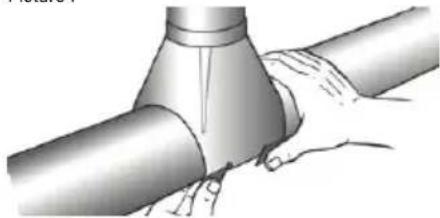
Mark the gutter at the point where the down pipe is to be located. Make two diagonal cuts with a hacksaw to create an aperture of approx. 10 cm (Picture G). Bend the edges of the gutter aperture down so that water will run off easily into the gutter outlet below (Picture H). Place the gutter outlet over the hole, ensuring that the hooked edge of the gutter outlet clips into the out-turned edge of the gutter. Press the gutter outlet against the gutter and fi x it in place using the lugs on the rear (Picture I & J).

natural_image
Illustration of hands using a tool to clamp or adjust a pipe fitting (no text or symbols visible)Picture G

natural_image
Illustration of a mechanical clamp or tool interacting with a cylindrical object (no text or symbols visible)Picture H

natural_image
Illustration of a hand holding a metallic pipe joint with dashed lines indicating a gap or stroke (no text or symbols present)Picture I
natural_image
Illustration of a hand holding a pipe fitting with a pointed tip (no text or symbols)Picture J
Picture F
3. GUTTER END
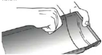
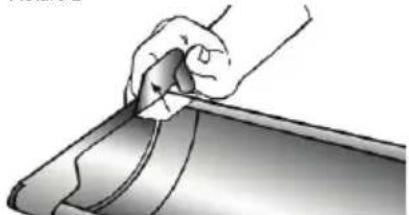
It is recommended to assemble the gutter end on the ground before installing the gutter. Fit the gutter end by twisting it into the end of the gutter, and apply a bead of metal sealant on the gutter (Picture K).
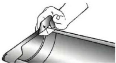
Press the gutter end down into the gutter and tap it into place (Picture L). The metal edge that is not required may, if you so wish, be snapped off at the existing notch (Picture M). Smooth out the sealant.

natural_image
Illustration of hands using a tool to apply or write on a surface (no text or symbols visible)Picture K

natural_image
Illustration of hands holding a flat sheet of paper (no text or symbols visible)Picture L
natural_image
Illustration of a hand holding a tool over a curved surface (no text or symbols)Picture M
4. GUTTER
Place the gutters in position and fasten them to the back edge of the hooks. Press the gutter down into the hook and bend over the securing plate on the hook to secure the gutter in place (Picture N).

natural_image
Illustration of hands connecting a pipe to a terminal block (no text or symbols visible)Picture N
5. GUTTER JOINT
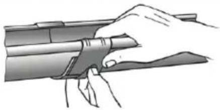
When joining sections of gutters, fi rst hook the back edge of the gutter joint round the gutters. Make sure that the back edge of the gutter joint is in contact with the gutters when you put the front clip over the edge of the gutters and then press the clip down Lock it in place with the small tongue (Picture O). It is important that the gutter joint is assembled straight against the gutter.
natural_image
Illustration of hands holding a rifle with a grip (no text or symbols visible)Picture 0
6. PIPE BEND AND INTERMEDIATE PIPE
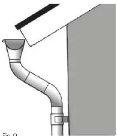
Assemble a pipe bend on the gutter outlet. Measure the distance between the pipe bends (Picture P). Cut the intermediate pipe about 12 cm longer than the distance between the pipe bends. Put the intermediate pipe into the lower pipe bend and assemble on to the upper pipe bend. Then assemble the down pipe. (Picture Q).

natural_image
Diagram of a bathroom sink with pipes and fixtures (no text or symbols)Picture P

natural_image
Illustration of a pipe fitting with a sloped outlet, no text or symbols presentPicture Q
7. PIPE WRAP
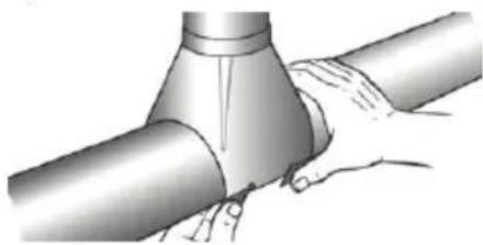
Fix a pipe wrap to the wall immediately below the completed bend (Picture Q). Fix the next pipe wrap straight below the first and so on. Max. 2 m between each wrap. Use screws if the pipe wraps are fastened in wood or screws and plugs when fastened in stone. There is also a special nail for fastening in stone walls available. When the pipe wraps are fastened on the wall the down pipe can be assembled. Press the pipe wrap together and tap the wedges into place using a block of wood or rubber mallet. (Picture S).

natural_image
Illustration of a hand using a tool to adjust or install a cylindrical component (no text or symbols visible)
natural_image
Illustration of hands using a hammer to adjust a vertical pole (no text or symbols)Picture S
8. WATER DRAINAGE
If connecting to the underground drainage system, fi t a drain trap sleeve (1) and a drain trap (2). Fit an extension pipe (3) outside the down pipe and slide it down to the drain trap (Picture T).
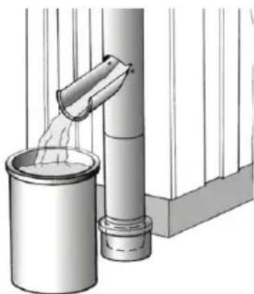
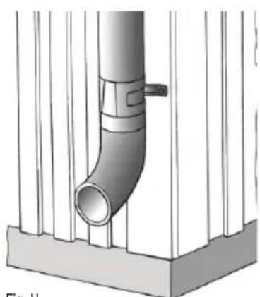
To simply conduct the water into the ground, fi t a shoe on to the drain pipe (Picture U). If you wish to collect rainwater in a butt, fi t a fold-out shoe. Fit, for example, a drain shoe to connect the down pipe to the drain (Picture V).

natural_image
Technical diagram of a mechanical assembly with a cylindrical component and internal structure (no text or symbols)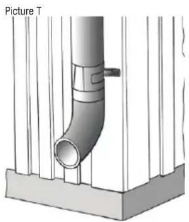
natural_image
Diagram of a pipe fitting with vertical supports, labeled 'Picture T' (no other text or symbols)
natural_image
Illustration of a pipe pouring liquid into a container, with no visible text or symbolsPicture V
9. ADJUSTABLE GUTTER HOOK
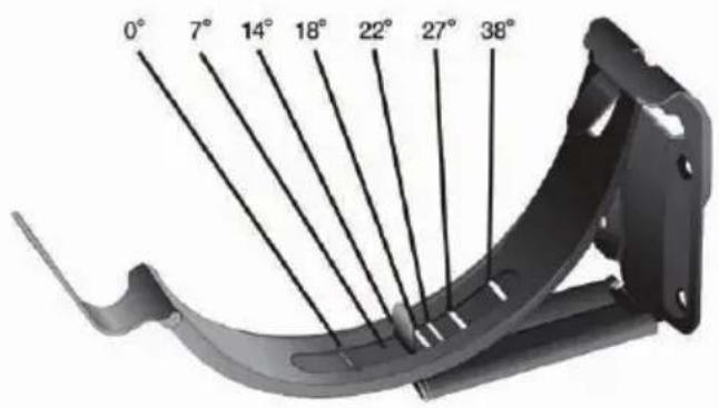
- Find out the approximate angle of the roof/eaves board (e.g. if section X is 40 cm then the roof angle is 14^ ).
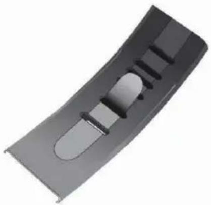
- Set required angle by sliding the securing plate into the correct groove on the gutter hook.
- Bend the securing plate to lock the gutter hook at the required angle. Press down the securing plate hard, use a suitable tool if necessary (for example pliers).
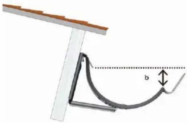
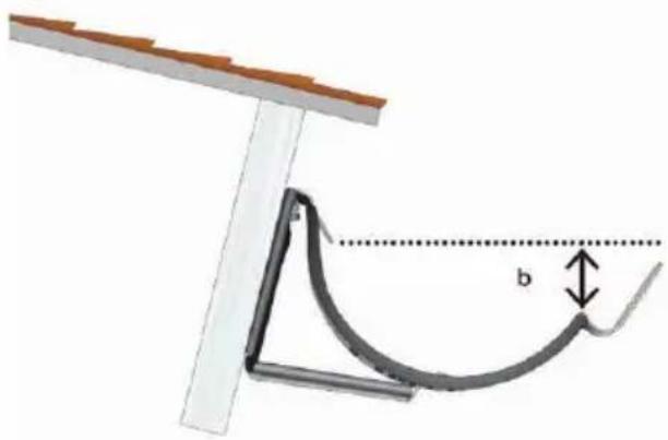
- Check the angle setting before setting the other gutter hooks. The front edge of the gutter hook on the horizontal plane should be approximately 25–30 mm under the back edge (b).
- When all hooks are set to required angle, screw them up with a horizontal slope of about 3–5 mm/m towards the down pipe (see also 1. Gutter hook).

3
natural_image
3D rendered image of a curved mechanical component with internal slots and a central slot (no text or symbols)4
natural_image
Diagram of a curved pipe or cable with labeled points a and b, showing a fixed support structure (no text or symbols beyond labels)2


- TAKAVVATTNING
- INNEHÅLL
- INTRODUKTION
- RÄNNGAVEL
- HÄNGRÄNNA
- RÄNNSKARV
- RÖRVINKEL OCH MELLANSTYCKE
- RÖRSVEP
- VATTENAVLEDNING
- STÄLLBAR RÄNNKROK
- ENDESTYKKE
- TAKRENNE
- RENNESKJ∅T
- R∅RVINKEL OG MELLOMSTYKKE
- NEDL∅PSKLAMMER
- DRENERING
- JUSTERBAR RENNEKROK
- KOURUN PÄÄTYKAPPALE
- RÄYSTÄSKOURU
- KOURULIITOS
- KULMAPUTKI JA VÄLIKAPPALE
- SYÖKSYPUTKEN KIINNIKE
- VEDEN POISTAMINEN
- SÄÄDETTÄVÄ KOURUKOUKKU
- RENDEJERN
- ENDEBUND
- TAGRENDE
- SAMLESTYKKE
- R∅RB∅JNING OG MELLEMSTYKKE
- R∅RHOLDER
- VANDAFLEDNING
- JUSTERBART RENDEJERN
- ROOF DRAINAGE
- CONTENTS
- INTRODUCTION
- GUTTER HOOK
- Gutter slope
- Bending of gutter hooks
- Gutter hooks for fascia board
- GUTTER OUTLET
- GUTTER END
- GUTTER
- GUTTER JOINT
- PIPE BEND AND INTERMEDIATE PIPE
- PIPE WRAP
- WATER DRAINAGE
- ADJUSTABLE GUTTER HOOK
Brand : Biltema
Model : 89-481
Category : Système de drainage