
APSUB-GM61 - Subwoofer PAC - Free user manual and instructions
Find the device manual for free APSUB-GM61 PAC in PDF.


| Product Type | Subwoofer Amplifier Interface for select GM vehicles |
| Brand | PAC |
| Model | APSUB-GM61 |
| Compatibility | GM vehicles with IO4, IO5, or IO6 radios (with or without Bose) |
| Input Signal | Full range fixed level from factory head unit via MOST data |
| Output Type | Variable 5V RMS pre-amp (switchable to 4V via DIP switch 2) |
| Low Pass Filter | 350Hz, 24dB/octave Linkwitz-Riley |
| Channels | 2-channel non-fading output |
| Remote Turn-On | Data controlled, 2A max output |
| Bass Level Control | Included wired knob; default 100% if disconnected |
| Minimum Volume Adjustment | Via programming button, factory dash controls, or AmpPRO PC app |
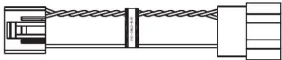
| Active Noise Cancellation (ANC) Bypass | Included ANC-GM03 harness disables factory ANC |
| DIP Switch Settings | 4 switches: output voltage, left channel workaround, etc. |
| PC Application | AmpPRO PC app for firmware updates and configuration |
| Factory Reset | Press programming button 10 sec until LEDs blink red |
| Power Supply | 12V DC vehicle electrical system |
| Installation Requirement | Factory amplifier must remain connected; aftermarket amplifier with solid ground |
| LED Indicators | Status LEDs: solid red (active), amber (adjustment mode), blinking (DSP activity) |
| Included Accessories | Module, harnesses, level control knob, ANC-GM03 harness |
| Technical Support | Email: support@PAC-audio.com, Phone: 727-592-5991, Chat: PAC-Audio.com |
Frequently Asked Questions - APSUB-GM61 PAC
User questions about APSUB-GM61 PAC
0 question about this device. Answer the ones you know or ask your own.
Ask a new question about this device
Download the instructions for your Subwoofer in PDF format for free! Find your manual APSUB-GM61 - PAC and take your electronic device back in hand. On this page are published all the documents necessary for the use of your device. APSUB-GM61 by PAC.
USER MANUAL APSUB-GM61 PAC
Introduction and Features
The APSUB-GM61 provides a 2-channel non-fading output for use with an aftermarket amplifier and subwoofer. Using the full range, fixed level head unit output, in conjunction with MOST data, the APSUB-GM61 delivers a variable 5v RMS pre-amp output with bass equalization and level control capabilities. The signal has a 350Hz / 24dB Linkwitz-Riley low pass filter applied. A data controlled remote amplifier turn on wire is also provided by the APSUB-GM61.
Important Notes
- This interface is compatible in vehicles with or without Bose that are equipped with IO4, IO5 or IO6 model radios.
- In some non-Bose radios, there may be absence of audio from the left channel when in AM, FM, and XM sources. The APSUB-GM61 is capable of providing a work-around by passing the right channel audio through the left and right channels when in the AM, FM and XM sources. All other sources will still offer left and right separation. See the troubleshooting section on page 6 for additional details.
- If originally equipped, the factory amplifier must remain in the vehicle, and connected after the APSUB-GM61 has been installed.
- The remote output is rated at 2A of current. If more current is needed, an external relay must be used.
- When the bass level control knob is not connected to the APSUB-GM61, the output level will default to 100% .
- The level control knob must be connected in order to manually adjust the minimum volume settings.
- The minimum volume level is set to a default value. If you are happy with this level in your particular application, then additional adjustment is not required. Please refer to the Setup and Configuration section on page 2 for more details.
- The factory radio's speed controlled volume and surround sound mode are not supported by the APSUB-GM61 outputs.
- No adjustments can be made manually using the programming button or the factory SWC when the module is connected to a PC.
- If the vehicle is equipped with Active Noise Cancellation (ANC), the ANC can be disabled using the included ANC-GM03 harness. See page 3.
The aftermarket amplifier must have a very solid ground and the amplifier power/ground connections should be made before connecting the RCA's or Remote Turn On to the APSUB-GM61
Wiring Connection Chart

flowchart
graph TD
    A["AP4-GM61-HAR"] --> B["To Tuner"]
    A --> C["To Vehicle Harness"]
    A --> D["Remote Turn On Output 2A Max Output"]
    E["Subwoofer Outputs"] --> F["Non-Fading Level Control Knob"]
    E --> G["To Aftermarket Amplifier"]
    H["ANC-GM03-HAR"] --> I["To Factory Amplifier"]
    H --> J["To Amplifier Harness"]
APSUB-GM61
Advanced Subwoofer Amplifier Interface for Select General Motors Vehicles
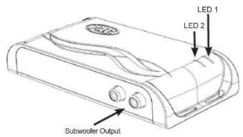
Module Layout

Installation

Set DIP switches to the ON position to activate the corresponding features. Set DIP switches to the OFF position for any features that are not desired.

| No Function 5v / | 4v Preout Troubleshooting | No Function | |
| 1 2 3 4 |
- Access the factory tuner module (see location info to the right).
- Disconnect the Gray 20-pin factory harness and the Gray 8-pin harness from the tuner module (Figure 1).
- Connect the APSUB harness to vehicle harness.
- Connect the APSUB harness to factory tuner module.
- Set any feature DIP switches that apply to your install. Set DIP switch 2 on (down) to lower the RCA output voltage to 4v. Leave DIP switch 2 off (up) to keep the RCA output voltage at 5v.
- Connect the APSUB harness to the APSUB module.
- Connect the level control knob to the module and install in an accessible location.
- After the aftermarket amplifier power/ground connections are made, connect the signal cables and remote input from the aftermarket amplifier to the APSUB.
- Turn the vehicle off, shut the doors and lock the vehicle with the factory key fob. Wait 5 minutes. After 5 minutes, turn vehicle back on, and proceed with setup and configuration.
| Vehicle | Tuner Module Location |
| Cadillac CT6 Back Passenger Sidewall of Trunk | |
| Cadillac (others) | Above Passenger Kick Panel |
| Chevrolet Corvette | Passenger Footwell on Firewall |
| Chevrolet Impala Chevrolet Camaro | Above Passenger Kick Panel |
| Full/Mid Size Trucks Behind Radio Display | |
| Full Size SUV | Behind Radio Display, Lower Dash |
| Chevrolet Equinox Chevrolet Traverse GMC Acadia GMC Terrain | Behind Glove Box-By Passenger Kick Panel |

Setup and Configuration
- Turn the ignition on. LED 1 on the interface will turn on and the +12v remote output will turn on.
- Set the amp gain(s) to the desired level. We recommend using an oscilloscope and test tones to set the amp gain(s). Please refer to the MECP Advanced study guide (p. 360) if you are unfamiliar with this process.
- Check volume, balance, fade and EQ settings.
- If you would like to adjust the minimum volume, do so using one of the methods outlined on the next page. If you are happy with the default levels, no adjustments are necessary.
Setup and Configuration (cont.)
Manually Setting the Minimum Volume (optional)
If the minimum volume of the radio (factory radio volume level 1) is too loud or too quiet, you can manually set the level of the minimum volume using either the programming button on the side of the interface or the radio dash panel controls. If you would like to set the minimum volume using the AmpPRO PC app, please proceed to the AmpPRO PC app section.
PLEASE NOTE: Level control knob must be connected to module for either of the following methods.
Setting the minimum volume using the programming button
- Start with the level control knob turned all the way down (counter-clockwise).
- Set the amp gains to the desired level.
- Set the volume on the factory radio to 1.
- Press the programming button on the side of the interface once.
- LED 1 will turn amber and the chimes will begin sounding every five seconds.
- Turn the level control knob clockwise until the desired minimum volume level is reached.
- You can now either press the programming button once or wait ten seconds to exit the settings.
Setting the minimum volume using the factory dash panel controls
- Start with the level control knob turned all the way down (counter-clockwise).
- Set the amp gains to the desired level.
- Set the volume on the factory radio to 1.
- LED 1 will turn amber and the chimes will begin sounding every five seconds.
- Turn the level control knob clockwise until the desired minimum volume level is reached.
-
You can now wait ten seconds to exit the settings.
-
Press and hold the track up button on the radio dash panel controls for approximately ten seconds. PLEASE NOTE: The radio will respond to the SWC commands during this process, this is normal and has no effect on the APSUB-GM61 operation.
Active Noise Cancellation (ANC) Bypass
When adding a subwoofer to a vehicle equipped with ANC, the ANC system will attempt to cancel out the bass frequencies being generated by the aftermarket subwoofer. This results in unwanted "noise" being produced by the factory speakers.
Identifying ANC in the Vehicle
GM vehicles with multiple microphones located in the door panels or headliner locations will usually be equipped with ANC. If you are unsure, the ANC-GM03 can be installed with no negative effect on vehicles not equipped with ANC.
Bypassing the ANC Signal
- Access the factory amplifier (see location info to the right).
- Disconnect the 16-pin factory harness from the amplifier.
- Plug in the ANC-GM03 harness into the amplifier.
- Connect the 16-pin factory harness to the ANC-GM03.
TO AMPLIFIER TO AMPLIFIER HARNESS
natural_image
Pure electrical circuit lines without any symbols| Vehicle | Amplifier Location |
| Chevrolet Equinox Chevrolet Traverse GMC Acadia GMC Terrain | Front of Center Console |
| Cadillac CT6 Chevrolet Camaro Chevrolet Corvette | Under Trunk Floor |
| Cadillac ATS Chevrolet Impala Chevrolet Malibu | Passenger Side of Trunk |
| Cadillac Escalade Chevrolet Suburban Chevrolet Tahoe GMC Yukon / XL | Driver Side Rear Quarter Panel |
| Chevrolet Silverado GMC Sierra | Behind Rear Seat Back |
Note: Some models are not included in this table because ANC is not an available option for those vehicles.
AmpPRO PC App
Use of the AmpPRO PC App allows you to do the following:
- Configure User Interface Options such as:
• Minimum Volume Level
- Enable / Disable Factory EQ
- Set Bass Center Frequencies and Q Factor
- Update Product Firmware
- Read Firmware / Hardware Versions
- You can download the AmpPRO app at :
https://pac-audio.com/app-downloads/
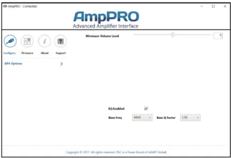
PLEASE NOTE: These settings can be adjusted with the module installed in the vehicle, or on the bench. However, it is recommended to make the adjustments with the module installed, and the factory radio on, so that the changes can be heard.
Minimum Volume Level - This allows you to set the minimum volume level of the factory radio (factory radio volume level 1).
EQ Enabled - This allows you to enable / disable the bass band factory EQ from adjusting the APSUB output.
Bass Freq / Q Factor - This allows you to set the center frequency that will be adjusted when using the bass band on the factory EQ, as well as the Q Factor for the frequency. The Q Factor determines how many of the adjacent frequencies will be affected when adjusting the selected frequency. The lower the Q Factor, the more frequencies will be affected. See below for available frequencies and Q Factors. Note: This setting only affects the output of the APSUB and does not change the way that the factory EQ adjusts the factory speakers.
F1: 60Hz Center Frequency | 0.50 Q Factor
F2: 100Hz Center Frequency | 2.00 Q Factor
| Bass Frequency | 60HZ |
| 80HZ | |
| 100HZ | |
| 120HZ | |
| Bass Q Factor | 0.50 |
| 1.00 | |
| 1.50 | |
| 2.00 |

line
| x | F1F2 | Other | | ---- | ----- | ----- | | 20 | +3 | 0 | | 63 | +12 | 0 | | 125 | +12 | 0 | | 250 | +6 | 0 | | 500 | +3 | 0 | | 1k | 0 | 0 | | 2k | 0 | 0 | | 4k | 0 | 0 | | 8k | 0 | 0 |AmpPRO PC App (cont.)
Firmware Updates
The AmpPRO PC app will also allow you to update the interface with new firmware as it becomes available. Please visit www.pac-audio.com or contact our tech support department to see if there is a firmware update for your interface.
To view Product Software and Hardware Version, connect the interface to your PC and select "About".
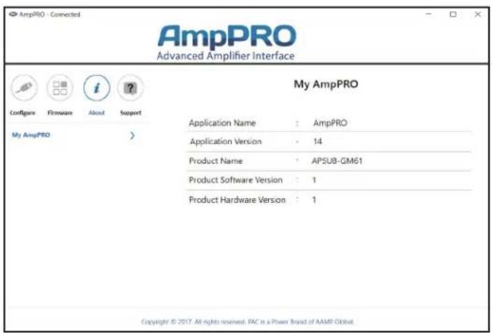
To update the firmware, connect the interface to your PC and select "Firmware", then "Update Firmware". Now select "Select File". Finally, browse to the place where you saved the file and select it. This will begin the updating process. Once finished, disconnect the interface from the PC and resume normal operation.


Restoring Factory Settings
You can restore the interface to factory default settings by pressing and holding the programming button on the side of the module for 10 seconds until the status LEDs start blinking red. Once the LEDs start blinking red, release the button.
This reset will restore the following settings to their factory defaults:
• Minimum volume level
- Enable / Disable factory EQ
• Factory EQ frequency
• Factory EQ Q factor
- Radio Tuner Setting (when set by using the Home button). See Troubleshooting section 3 for more information.
Troubleshooting
- Low volume setting on radio is too loud - Set the minimum volume using process outlined in Setup and Configuration, or using the AmpPRO PC app.
- If for any reason the APSUB module becomes unresponsive, or will not power up with the key on, you can always reset the interface by turning the key to the ignition position, then pressing and holding the Power button on the factory radio for 12 seconds or by pressing and holding the reset button on the side of the APSUB module for 10 seconds (until the LEDs alternate flashing red).
- No audio out of the left channel when in AM, FM or XM bands (only seen in non-Bose applications) - If you have access to the APSUB-GM61, flip DIP switch 3 down (on). If you do not have access to the APSUB-GM61, press and hold the Home button (on the radio control panel) for 12 seconds until 2 chimes are heard through the radio. After this setting is enabled, when in AM, FM, or XM sources, the left channel audio is a duplicate of the right channel audio. The other audio sources will not be affected and will still have true stereo separation.
| LED Legend | ||
| LED 1 | Action/Color During | Normal Operation |
| Solid Red Module Active | ||
| Solid Amber Minimum Volume | me Adjustment Mode | |
| Rapid Blink Any Color DSP | Activity | |
| LED 2 Blinking Amber USB Connection | Detected | |
| Both LEDs Alternate Blinking Red Performing Memory Reset | ||
Technical Support
Email: support@PAC-audio.com
Phone: 727-592-5991
Chat: PAC-Audio.com
- Introduction and Features
- Important Notes
- APSUB-GM61
- Installation
- Setup and Configuration
- Setup and Configuration (cont.)
- Manually Setting the Minimum Volume (optional)
- PLEASE NOTE: Level control knob must be connected to module for either of the following methods.
- Setting the minimum volume using the programming button
- Setting the minimum volume using the factory dash panel controls
- Active Noise Cancellation (ANC) Bypass
- Identifying ANC in the Vehicle
- Bypassing the ANC Signal
- AmpPRO PC App
- Use of the AmpPRO PC App allows you to do the following:
- AmpPRO PC App (cont.)
- Firmware Updates
- Restoring Factory Settings
- Troubleshooting
- Technical Support
Brand : PAC
Model : APSUB-GM61
Category : Subwoofer