
HYWP4300X - Water pump HYUNDAI - Free user manual and instructions
Find the device manual for free HYWP4300X HYUNDAI in PDF.

| Product Type | Petrol Water Pump |
| Brand | Hyundai |
| Model | HYWP4300X |
| Engine Type | Air-Cooled 2-Stroke |
| Displacement | 42.7 cc |
| Maximum Output | 1.35 kW / 7000 rpm |
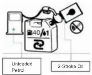
| Fuel Mixture | Unleaded petrol + Semi-synthetic 2-stroke oil (40:1) |
| Carburetor | Diaphragm type |
| Fuel Tank Capacity | 1.6 L |
| Starting System | Recoil start |
| Suction Port Diameter | 38.1 mm (1.5 inch) |
| Discharge Port Diameter | 38.1 mm (1.5 inch) |
| Maximum Suction Height | 8 m |
| Maximum Head | 30 m |
| Maximum Flow Rate | 250 L/min |
| Sound Pressure Level | 98.7 dB(A) (K=3) |
| Sound Power Level | 111.3 dB(A) (K=3) |
| Dimensions (L x W x H) | 33 x 38 x 39 cm |
| Safety Features | Carbon monoxide warning; must use outdoors; PPE required |
| Maintenance | Air filter cleaning; spark plug gap 0.6-0.7mm; fuel filter cleaning |
| Warranty | Information available at www.hyundaipowerproducts.co.uk |
Frequently Asked Questions - HYWP4300X HYUNDAI
User questions about HYWP4300X HYUNDAI
0 question about this device. Answer the ones you know or ask your own.
Ask a new question about this device
Download the instructions for your Water pump in PDF format for free! Find your manual HYWP4300X - HYUNDAI and take your electronic device back in hand. On this page are published all the documents necessary for the use of your device. HYWP4300X by HYUNDAI.
USER MANUAL HYWP4300X HYUNDAI
natural_image
Technical line drawing of a mechanical pump assembly (no text or symbols)CONTENTS
- SAFETY 4-7
- PART LOCATIONS 8
- FUEL 9
- SETUP 10-11
- OPERATION 12 – 13
- MAINTENANCE 13 – 15
- TROUBLESHOOTING 15
- SPECIFICATION 16
- STORAGE & TRANSPORTATION 17
- CONTACT DETAILS / WARRANTY 18
- DECLARATIONS of CONFORMITY 19
1. SAFETY


1.1. The operator of the machines;
1.1.1. Responsible for and has a duty of care in making sure that the machine is operated safely and in accordance with the instructions in this user manual.
1.1.2. Should never be left it in a condition which would allow an untrained or unauthorised person/s to operate this machine.
1.1.3. All due care and diligence should be taken by the operator for the safety of and with regard to those around whilst using the machine, to include but not limited to; elderly, children, pets, livestock and property.
1.1.4. Some or all of the following PPE, Warning Signs and symbols may appear throughout this manual and you must adhere to their warning. Failure to do so may result in personal injury.
Personal Protective Equipment(PPE)

| Warning Signs and Symbols – FOLLOW safety messages to avoid or reduce risk of injury or death. | ||||||
| !DANGERDANGER-indicates WARNING-indicates CAUTION - indicates NOTE -indicatesahazard whichifnot hazard which ifnot hazard which if not situationthatcouldavoided could result in avoidedcould resultin avol-derd might result easily result inseriousinjuryor seriousinjuryor in minor or equipment damage.death. death. | !CAUTION | !NOTE | READ MANUAL | |||
 EXPLOSION EXPLOSION |  FIRE FIRE |  ELECTRIC SHOCK ELECTRIC SHOCK |  KICKBACK KICKBACK | |||
 HOT SURFACE HOT SURFACE |  TOXIC FUMES TOXIC FUMES |  SLIPPERY SLIPPERY |  MOVING PARTS MOVING PARTS | |||
1.2. Carbon Monoxide.
1.2.1. Carbon Monoxide is a colorless and odorless gas, inhaling this gas can cause death as well as serious long term health problems such as brain damage.
1.2.2. The symptoms of carbon monoxide poisoning can include the following; headaches, dizziness, nausea, breathlessness, collapsing or loss of consciousness.
1.2.3. Carbon Monoxide symptoms are similar to flu, food poisoning, viral infections and simply tiredness. That's why it's quite common for people to mistake this very dangerous poisoning for something else.
1.2.4. To avoid Carbon Monoxide poisoning DO NOT Use Petrol/Diesel powered equipment inside a home or garage even if doors and windows are open.
1.2.5. If you think you or someone around you has been affected by Carbon Monoxide poisoning;
• Get fresh air immediately.
- Open doors and windows, turn off machine and leave the affected area.
- Open doors and windows, turn off machine and leave the affected area.
- See your doctor immediately or go to hospital and let them know that you suspect Carbon Monoxide poisoning.
1.2.6. DO NOT use in an enclosed area or a moving vehicle.

1.3 General fuel safety.
1.3.2. Fuel Safety additional information can be obtained from the Health and Safety Executive (HSE) document SR16.

CAUTION
All fuels are Flammable.
1.3.3. Keep away from all ignition sources i.e. heaters, lamps, sparks from grinding or welding.
1.3.4. Hot workon tanksthat have contained fuel is extremelydangerous and shouldnot be carriedout.
1.3.5. Keep work area clean and tidy.
1.3.6. Clean up all spills promptly using correct methods.e. absorbent granules and a lidded bin.
1.3.7. Dispose of waste fuels correctly
1.4. Petrol safety.

1.4.1. Always fuel and defuel in well-ventilated area. Always wear correct, suitable and fit for purpose Personal Protective Equipment (PPE), suggested items are as follows, but are not limited too.

Hand protection.
Protective clothing.
Respiratory protective equipment should be used when in an unventilated area.
1.4.1.1. When defuelingalways use a propriety fuel retriever.
1.4.1.2. Always carry fuel in the correct and clearly marked container.
1.4.2. Additional safety.
1.4.2.1. Intended use is for pumping the water that is not intended for human consumption. Pumping flammable liquids, such as petrol or fuel oils, can result in a fire or explosion, causing serious injury. Pumping sea water, beverages, acids, chemical solutions, or any other liquid that promotes corrosion can damage the pump.
1.4.2.2. Always be sure to include this manual when selling, lending, or otherwise transferring the ownership of this product.
1.4.2.3. Never allow children or anyone unable to fully understand the directions given in the manual to use the machine.
1.4.2.4. During transportation close the fuel cock and the fuel tank cap.
Empty the fuel tank during transportation on long distances or rough roads.
1.4.2.5. Don't use the engine pump near people or animals.
1.4.2.6. Do not use the pump set close to cables or electrical equipment.
1.4.2.7. Keep the running (or still hot) pump away from any inflammable material.
1.4.2.8. Be careful with the muffler or other hot engine parts. During transportation close the fuel cock and the fuel tank cap. Empty the fuel tank during transportation on long distances or rough roads.
1.4.2.9. Only use the pump in well-ventilated places, do not operate the pump in explosive or flammable atmospheres or in closed environments.
1.4.2.10. Check the pump each day to ensure that each device, whether for safety or otherwise, is functional.
1.4.2.11. Never use a damaged, modified, or improperly repaired or assembled pump. Do not remove, damage or deactivate any of the safety devices.
1.4.2.12. Never carry out operations or repairs on your own that are other than routine maintenance. Call specialized and authorized workshops only.
1.4.2.13. Keep the pump set in a dry place, raised off the ground and with the tanks empty.
1.4.2.14. If your pump is no longer usable, dispose of it properly without damaging the environment by handing it in to your local Dealer who will arrange for its correct disposal.
1.4.2.15. Take it to your dealer who will dispose of it properly. Always call your dealer for any clarification or priority action.
1.4.3. Check the General Condition of the Pump
1.4.3.1. Look around and underneath the pump for signs of oil or gasoline leaks.
1.4.3.2. Remove any excessive dirt or debris, especially around the engine muffler, and recoil starter.
1.4.4. Look For Signs Of Damage
1.4.4.1. Check that all nuts, bolts, screws, hose connectors and clamps are tightened.
1.4.5. Check The Suction And Discharge Hoses
1.4.5.1. Check the general condition of the hoses. Be sure the hoses are in serviceable condition before connecting them to the pump. Remember that the suction hose must be reinforced construction to prevent hose collapse.
1.4.5.2. Check that the sealing washer in the suction hose connector is in good condition.
1.4.5.3 Check that the hose connectors and clamps are securely installed.
1.4.5.4. Check the the strainer is in good condition and is installed on the suction hose.
N.B. If there is the slightest of air leaks in the suction side, the pump will not prime.
1.4.6. Check the Engine
1.4.6.1 Check the engine oil level. Running the engine with a low oil level can cause engine damage.
1.4.6.2. Check the air filter. A dirty air filter will restrict air flow to the carburetor, reducing engine and pump performance.
1.4.6.3. Check the fuel level. Starting with a full tank will help to eliminate or reduce operating interruptions for refueling.
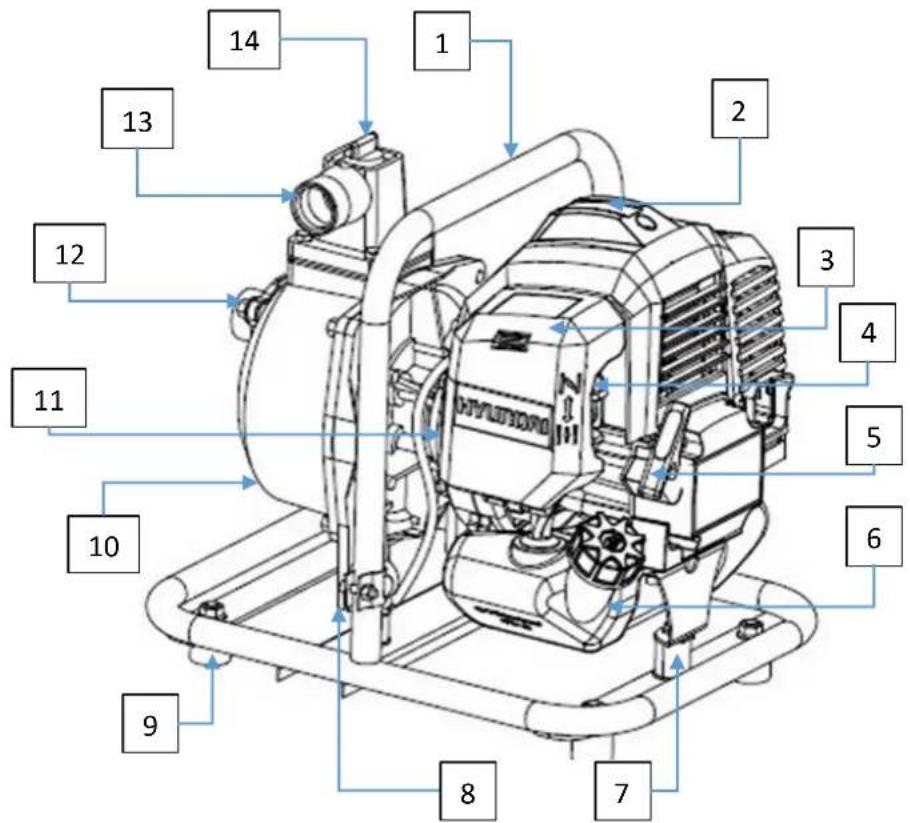
1 – Carrying handle
5 – Recoil handle
9 - Rubber foot
13 – Discharge port
2 - Spark plug
6 - Fuel tank
10 – Pump drain plug
2 - Air filter cover
5 – Spark arrester/exhaust
3 - Primer bulb
6 - Starter recoil handle
3. FUEL

WARNING

Petrol is highly inflammable. Avoid smoking or bringing any source of ignition or naked flame near fuel, this includes tools which can cause sparks such as grinders and drills. Before refueling make sure the engine has been stopped and allowed to cool down. Choose an outdoor area at least 10m from fuel
storagepoint.
3.3. DO NOT use straight unleaded fuel.
3.4. DO NOT use 4-stroke engine oil.
3.5. YOU MUST use an unleaded fuel and Semi-synthetic 2-stroke oil mixture.
3.5.1. For the first time ONLY a mixing ratio of 25:1 should be used to lubricate all engine parts to an optimum level. Thereafter the mix is 40:1.
3.6 How to mix the Petrol/Oil mixture.
3.6.1. Measure the required quantities of unleaded petrol and 2 stroke oil.
3.6.2. Put some of the unleaded petrol into an approved clean container. Mark the container stating that it is an unleaded petrol / 2-stroke oil mixture.
3.6.3. Pour in all of the 2 stroke oil. Mix the mixture until well mixed.
3.6.4. Pour in the remaining unleaded petrol and mix well for at least one minute. If the mixture has not been fully mixed there is a danger of the piston jamming due to insufficient oil.
| Petrol | Semi-Synthetic2-Stroke Oil |
| 2L | 50ml |
| 3L | 75ml |
| 4L | 100ml |
| Method of mixing | 40 parts petrol + 1 part2-stroke oil |
3.7 Fueling The Machine
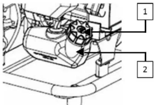
3.7.1. Untwist and remove the fuel cap (1), make sure that the fuel tank inlet is kept free of any debris and DO NOT allow any debris to enter the fuel tank (2).
3.7.2. DO NOT overfill - fill to approx. 80% of normal full capacity to allow for expansion.
3.7.3. Replace the fuel cap and make sure it is fully tightened. DO NOT use the machine without having the fuel cap fitted.
Fuel tank capacity 800ml (0.8L)
3.7.4. Fuel mixture which has not been used for over a month or more will clog the carburettor causing the engine to operate incorrectly. DO NOT dispose of used fuel down a drain or allow it to drain into a warehouse. YOU MUST dispose of unused fuel at an authorised recycling point.
4.1. Pump placement.
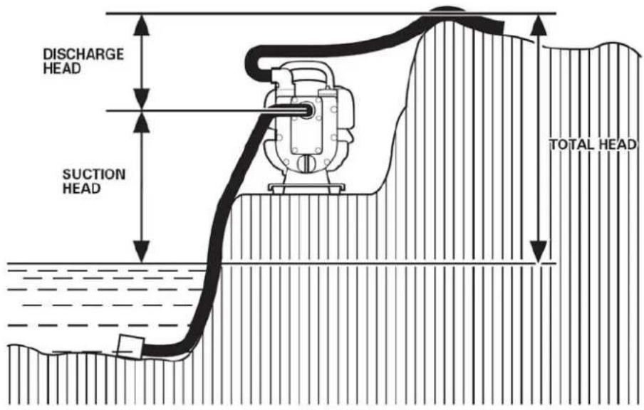
4.1.1. For best pump performance, place the pump near the water level, and use hoses that are no longer than necessary. This will enable the pump to produce the greatest output with the least self-priming time.
4.1.2. As head (pumping height) increases, pump output decreases. The length, type, and size of the suction and discharge hoses can also significantly affect pump output.
4.1.3. Discharge head capability is always greater than suction head capability, so it is important for suction head to be the shorter part of total head.
4.1.4. Minimizing suction head (placing the pump near the water level) is also very important for reducing self-priming time. Self-priming time is the time it takes the pump to bring the water along the distance of the suction head during initial operation.
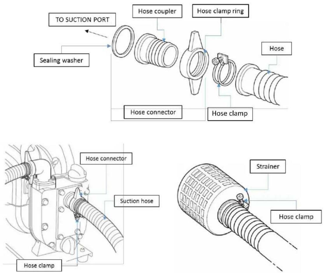
4.2. Suction head installation.
4.2.1. Use a rigid hose, hose connector and hose clamp provided with the pump. The suction hose must be reinforced with a non-collapsible wall or braided wire construction to prevent suction hose collapse.
4.2.2. The suction hose should be no longer than necessary. Pump performance is best when the pump is near the water level, and the hoses are short.
4.2.3. Never use a suction hose with an inside diameter less than 25 mm (1 inch).
4.2.4. Use a hose clamp to securely fasten the hose connector to the suction hose in order to prevent air leakage and loss of suction. Verify that the hose connector sealing washer is in good condition.
4.2.5. Install the strainer (provided with the pump) on the other end of the suction hose, and secure it with a hose clamp. The strainer will help to prevent the pump from becoming clogged or damaged by debris.
4.2.6. Securely tighten the hose connector on the pump suction port.
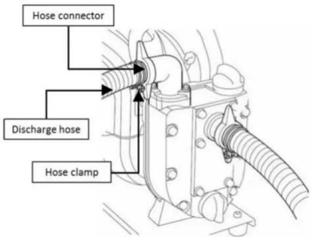
4.3. Discharge hose installation.
4.3.1. Attach a hose and hose connector to the pump's discharge port. It is best to use a short, large-diameter hose, because this will reduce fluid friction and improve pump performance. LayFlat hose can be used.
4.3.2. A long or small-diameter hose will increase fluid friction and reduce pump output.
4.3.3. If the discharge hose is equipped with a shutoff valve or nozzle, do not shut off the discharge water for a long period of time, as that could cause the pump to overheat.
5. OPERATION

NOTE
DO NOT operate the pump in a dry state.
Operating the pump dry will destroy the pump seal. If the pump has been operated dry, stop the engine immediately, and allow the pump to cool before priming.
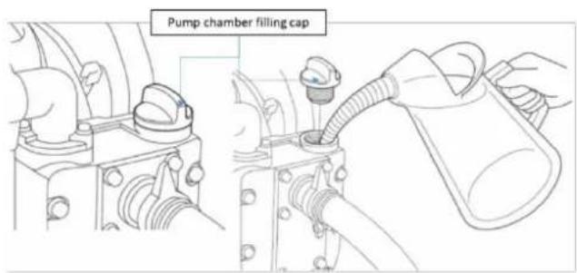
5.1. Priming the pump.
5.1.1. Before starting the engine, remove the filler cap from the pump chamber, and completely fill the pump chamber with water. Reinstall the filler cap, and tighten it securely.
5.2. Starting engine.
5.2.1. Rest the unit on a flat, firm place.
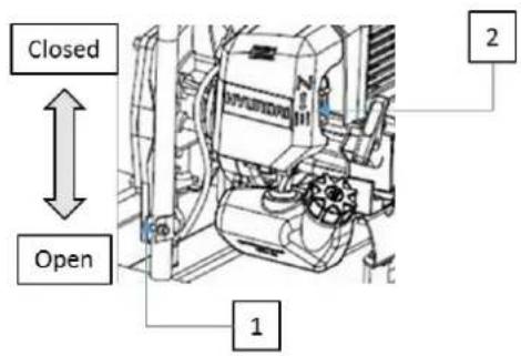
5.2.2. To start a cold engine, move the choke lever (2) UP to the CLOSED or START position.
5.2.3. Move the throttle lever (1) away from the IDLE position, but no further than the halfway point.
5.2.4. While holding the unit firmly, pull out the starter rope quickly until engine fires.
5.2.5. Move the choke lever (2) DOWN to the OPEN or RUN position, and pull out the starter rope quickly to start engine. DO NOT let go of the recoil starter handle instead allow it to return slowly.
5.2.6. Allow the engine to warm up for several minutes before starting operation.

NOTE
When restarting the engine immediately after stopping it, leave the choke open in the RUN position and push the primer pump several times.
Over-choking can make the engine hard to start due to excess fuel.
When the engine fails to start after several attempts, open the choke and repeat pulling the rope, or remove the spark plug and dry it.
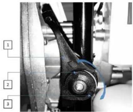
5.3. Setting engine speed.
5.3.1. After starting the engine, move the throttle lever (1) clockwise to the HIGH position (2) and check pump output.
5.3.2. Pump output is controlled by adjusting engine speed. Moving the throttle lever in the HIGH direction (2) will increase pump output, and moving the throttle lever (anti-clockwise) in the LOW direction (3) will decrease pump output.
5.4. Stopping the engine.

NOTE
Except for an emergency, avoid stopping the engine while pulling the throttle lever.
After use, remove the pump drain plug, and drain the pump chamber. Remove the filler cap, and flush the pump chamber with clean, fresh water. Allow the water to drain from the pump chamber, then reinstall the filler cap and drain plug.
5.4.1. Move the throttle lever (1) to the LOW position and run the engine for a half minute.
5.4.2. Press the STOP button until engine fully stops.
5.5. Adjusting the idling speed.

NOTE
Warm up the engine before adjusting the idling speed.
5.5.1. When the engine stops frequently at idling mode, turn the adjusting screw clockwise.
6. MAINTENANCE

WARNING
Before cleaning, inspecting or repairing the water, make sure that the engine has stopped and cooled down. Disconnect the spark plug to avoid accidental engine starts.
6.1. Daily Inspection
6.1.2. Check all nuts and screws are securely tightened and no parts are missing.
6.1.3. Before using machine replace any missing fixing nuts and screws.
6.1.4. Check for leakage offuel.
6.1.5. Clear up all fuel spills immediately, repair any leaks before starting the engine.
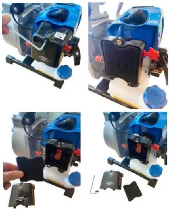
6.2. Air filter.
6.2.1. Check the air filter monthly.
6.2.2. To remove filter, undo the hex-screw with an Allen key to reveal filter element.
6.2.3. Clean the element in warm soapy water as necessary. Dry completely before installing.
6.2.4. You must clean more frequently if used under very dusty conditions.
6.2.5. Replace damaged filter.
6.2.6. DO NOT run machine without filter fitted.
natural_image
Four-panel photo collage showing a blue industrial machine with attached components, being handled and assembled (no visible text or symbols)6.3. Spark plug.
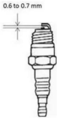
Check the sparkplug every 50 hours of use and clean the gap with a wire brush. The gap should be set to 0.6 - 0.7mm. When replacing with a new
6.3.1. plug, use a Champion RCJ-6Y or NGK BPMR7A.

WARNING
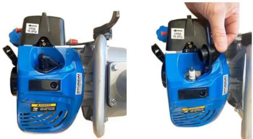
The spark plug MUST be fully tightened otherwise the engine will overheat causing damage. Always complete the following steps with the engine off and cooled.
6.3.2. Undo retaining screw and lift spark plug cover clear.
6.3.3. Disconnect the spark plug cap carefully. Do not pull on the HT lead instead pull on the spark plug cap.
6.3.4. Using the supplied spark plug wrench unscrew the spark plug in an anti-clockwise direction.
6.3.5. Check the spark plug visually for damage and electrode consumption, remove the carbon deposits.
6.3.6. Check the gap with a feeler gauge and turn the electrode on the right distance of 0.6 to 0.7mm.
6.3.7. To re-insert spark plug tighten up gently by hand to avoid cross threading, once done tighten it using a box spanner 14 turn more.
natural_image
Two blue Hyundai 3D lawn curling machines with visible brand labels and a hand adjusting the blade (no text or symbols on the machines themselves)6.3.9. Make sure the spark plugs tightened correctly otherwise damage can occur.
6.3.10. Refit the spark plug cap onto the sparkplug.

NOTE
The use of any spark plug other than the one designated may result in the engine failing to run correctly becoming overheated and damaged.
6.4. Fuel filter.

NOTE A clogged fuel filter can cause lack of power and poor pickup.
6.4.1. Remove the fuel cap (1) and empty the remaining fuel into an approved container.
6.4.2. With a small wire hook, pull the fuel line and filter (2) out of tank.
6.4.3. Disconnect the filterassembly.
6.4.4. If necessary, replace with new filter or clean by blowing air inside out.

7. TROUBLESHOOTING
| STARTING FAILURE | ||
| CHECK | POSSIBLE CAUSE | CORRECTIVE ACTION |
| Fuel tank | Incorrect fuel | Drain tank and fill with correct fuel |
| Fuel filter | Fuel filter element is clogged | Clean and/or replace |
| Carburetor adjustment | Out of normal range | Adjust |
| No spark | Spark plug is wet or fouled | Dry and clean |
| Incorrect gap | Adjust to correct gap 0.6mm to 0.7mm | |
| Spark plug | Disconnected | Connect |
| ENGINE STARTS BUT KEEPS STOPPING – HARD TO RE-START | ||
| CHECK | POSSIBLE CAUSE | CORRECTIVE ACTION |
| Fuel tank | Incorrect or stale fuel | Drain tank and fill with correct fuel |
| Carburetor adjustment | Out of normal range | Adjust |
| Exhaust port | Excessive carbon build up | Clean |
| Air Filter | Blocked with dust | Wash and/or replace |
| Cylinder fins/Fan cover | Blocked with dust | Clean |
| PUMP | ||
| CHECK | POSSIBLE CAUSE | CORRECTIVE ACTION |
| Pump does not turn | Engine does not start | Refer to engine manual |
| Impeller stuck/stiff | Dis-assemble and clean | |
| Pumping volume low | Air gap at suction side | Check for air leaks |
| Failed mechanical seal | Replace seal | |
| High suction lift | Lower lift height | |
| Pump not drawing in water | Not primed | Prime |
| Air allowed to enter mechanical seal | Replace seal | |
| Suction of air at suction side | Check all seals at suction side | |
| Drain plug loose | Tighten/check seal | |
8. SPECIFICATION
| Model | HYWP4300X |
| Engine | Air-Cooled 2-Stroke |
| Displacement | 42.7cc |
| Max. Output | 1.35kW / 7000rpm |
| Fuel | 40 Unleaded Petrol : 1 Semi-Synthetic 2-Stroke Oil |
| Carburettor | Diaphragm Type |
| Fuel Tank Capacity | 1.6L |
| Starting System | Recoil |
| Suction & Displacement Port | 38.1mm (1.5inch) |
| Pipe Diameter | 38.1mm (1.5inch) |
| Max. Suction | 8m |
| Max. Head | 30-35mm |
| Max. Flow | 25mm : 140L/min40mm : 250L/min |
| A-Weighted Sound Pressure Level | 98.67dB(A), K=3dB(A) |
| A-Weighted Sound Power Level | 111.30dB(A), K=3dB(A) |
| Dimensions | 33 x 38 x 39cm |

WARNING
If you do not follow these steps, deposit may arise in the carburettor. This will cause starting difficulties and may cause permanent damage.
9.1. Perform all the general maintenance that the maintenance section of your 'User Manual' is recommended.
9.2. Clean the outside of the machine.
9.3. Remove all fuel from the fuel tank.
9.4. After all the fuel is drained, start the engine.
9.5. Allow the engine to run in idle until engine stops alone. This allows the fuel to be removed from the carburetor.
9.6. Allow engine to cool down (about 5 minutes).
9.7. Use a sparkplug wrench, removethe spark plug.
9.8. Pour 1 teaspoon of clean 2-cycle oil into the combustion chamber. Slowly pull the starter rope severaltimes to coat internal components. Replace the sparkplug.
9.9. Store the machine in a cool, dry place away from any source of ignition such as an oil burner, waterheater etc.
9.10. Transporting the machine.
9.11 When transporting the machine make sure that no fuel is allowed to leak out. DO NOT allow the pump to come into contact with persons, animals and property.
10. CONTACT DETAILS
10.1. Postal address
Genpower Limited, Isaac Way, Pembroke Dock, Pembrokeshire, SA724RW, UK.
10.2. Telephone
+44 (0)1646 687880
10.3. Email
aftersales@hyundaipowerproducts.co.uk
10.4. Website
www.hyundaipowerproducts.co.uk
11. WARRANTY
For warranty information, please visit www.hyundaipowerproducts.co.uk
Proof of purchase will be required before you make a warranty claim.
EC Declaration of Conformity
We hereby declare that the machine detailed in this declaration complies to all the relevant provisions of the following EC directives.
• 2006/42/EC The Machinery Directive
• 2014/30/EU Annex II Electromagnetic Compatibility Directive
• 2016/1628/EC The Emission of Gaseous and Particulate Pollutants from internal Combustion engines
• 2000/14/EC Noise Emissions in the Environment by Equipment for use Outdoors.
And is in conformity with the applicable requirements of the following documents:
• EN ISO 11806-1:2011
• EN ISO 10517:2019
Declaration for 2000/14/EC Noise Emissions in the Environment by Equipment for use Outdoors.
Notified Body for EC Directive 2000/14/EC TÜV Rheinland (Shanghai) Co., Ltd.
| Model | Type | Engine Size | Measured Sound Power | Guaranteed Sound Power | Engine output |
| HYWP4300X | Petrol Water Pump | 42.7cc | 111.3dB(A) | 112dB(A) | 1.35kW |
Product Details
Brand : HYUNDAI
Model : HYWP4300X
Description : Petrol Water Pump
Name and address of technical documentation holder and EU distributor:
Genpower Ltd, Isaac Way, Pembroke Dock, Pembrokeshire, SA72 4RW, UK.
Signed by:

Roland Llewellin, Managing Director
Date: 16/04/2020
Importer:
GENPOWER LTD
Isaac Way, London Road
Pembroke Dock, UNITED KINGDOM, SA72 4RW
T: +44 (0) 1646 687 880 F: +44 (0) 1646 686 198
E: info@hyundaipowerproducts.co.uk
www.hyundaipowerproducts.co.uk
Imported/Distributed by GENPOWER LTD for The United Kingdom & Ireland

- CONTENTS
- SAFETY
- The operator of the machines;
- Personal Protective Equipment(PPE)
- Carbon Monoxide.
- General fuel safety.
- CAUTION
- All fuels are Flammable.
- Petrol safety.
- Additional safety.
- Check the General Condition of the Pump
- Look For Signs Of Damage
- Check The Suction And Discharge Hoses
- Check the Engine
- FUEL
- WARNING
- How to mix the Petrol/Oil mixture.
- Fueling The Machine
- Pump placement.
- Suction head installation.
- Discharge hose installation.
- OPERATION
- NOTE
- Priming the pump.
- Starting engine.
- Setting engine speed.
- Stopping the engine.
- Adjusting the idling speed.
- MAINTENANCE
- Daily Inspection
- Air filter.
- Spark plug.
- Fuel filter.
- TROUBLESHOOTING
- SPECIFICATION
- CONTACT DETAILS
- WARRANTY
- EC Declaration of Conformity
- Product Details
Brand : HYUNDAI
Model : HYWP4300X
Category : Water pump