PTZIP412X15WIR - Surveillance Camera LTS - Free user manual and instructions
Find the device manual for free PTZIP412X15WIR LTS in PDF.


| Product Type | Network PTZ Camera |
| Model | PTZIP412X15WIR |
| Series | PTZIP4XX |
| Power Supply | 12 VDC or 24 VAC (SELV, Limited Power Source) |
| Video Output | BNC (for test) |
| Audio Input | Yes (AUDIO-IN) |
| Alarm Input/Output | Yes (ALARM-IN, ALARM-OUT) |
| Network Interface | RJ45 Ethernet |
| Memory Card Slot | MicroSD (for local storage) |
| PTZ Control | Yes (pan, tilt, zoom, 3D positioning) |
| Day/Night | Auto switch with IR |
| 3D DNR | Yes |
| Optical Zoom | Yes (integrated optical zoom lens) |
| Mounting Options | Ceiling, Wall, In-ceiling (additional accessories for pendant/junction box) |
| Cable Routing | Top or side of back box |
| Default IP Address | 192.0.0.64 |
| Activation | Required strong password (min 8 chars, 3 of 4 categories) |
| Supported OS | Windows XP/Vista/7/Server 2003/2008 (32-bit) |
| Supported Browsers | Internet Explorer 8+, Safari 5.02+, Firefox 5+, Chrome 18+ |
| Compliance | FCC Class A, CE, ICES-003 |
Frequently Asked Questions - PTZIP412X15WIR LTS
User questions about PTZIP412X15WIR LTS
0 question about this device. Answer the ones you know or ask your own.
Ask a new question about this device
Download the instructions for your Surveillance Camera in PDF format for free! Find your manual PTZIP412X15WIR - LTS and take your electronic device back in hand. On this page are published all the documents necessary for the use of your device. PTZIP412X15WIR by LTS.
USER MANUAL PTZIP412X15WIR LTS
This Manual is applicable to Network PTZ Camera.
The Manual includes instrucons for using and managing the product. Pictures, charts, images and all other informaon hereinaer are for descripon and explanaon only. The informaon contained in the Manual is subject to change, without noce, due to rmware updates or other reasons. Please nd the latest version in the company website.
Please use this user manual under the guidance of professionals.
Legal Disclaimer
TO THE MAXIMUM EXTENT PERMITTED BY APPLICABLE LAW, THE PRODUCT DESCRIBED, WITH ITS HARDWARE, SOFTWARE AND FIRMWARE, IS PROVIDED "AS IS", WITH ALL FAULTS AND ERRORS, AND OUR COMPANY MAKES NO WARRANTIES, EXPRESS OR IMPLIED, INCLUDING WITHOUT LIMITATION, MERCHANTABILITY, SATISFACTORY QUALITY, FITNESS FOR A PARTICULAR PURPOSE, AND NON-INFRINGEMENT OF THIRD PARTY. IN NO EVENT WILL OUR COMPANY, ITS DIRECTORS, OFFICERS, EMPLOYEES, OR AGENTS BE LIABLE TO YOU FOR ANY SPECIAL, CONSEQUENTIAL, INCIDENTAL, OR INDIRECT DAMAGES, INCLUDING, AMONG OTHERS, DAMAGES FOR LOSS OF BUSINESS PROFITS, BUSINESS INTERRUPTION, OR LOSS OF DATA OR DOCUMENTATION, IN CONNECTION WITH THE USE OF THIS PRODUCT, EVEN IF OUR COMPANY HAS BEEN ADVISED OF THE POSSIBILITY OF SUCH DAMAGES.
REGARDING TO THE PRODUCT WITH INTERNET ACCESS, THE USE OF PRODUCT SHALL BE WHOLLY AT YOUR OWN RISKS. OUR COMPANY
SHALL NOT TAKE ANY RESPONSIBILITES FOR ABNORMAL OPERATION, PRIVACY LEAKAGE OR OTHER DAMAGES RESULTING FROM CYBER ATTACK, HACKER ATTACK, VIRUS INSPECTION, OR OTHER INTERNET SECURITY RISKS; HOWEVER, OUR COMPANY WILL PROVIDE TIMELY TECHNICAL SUPPORT IF REQUIRED.
SURVEILLANCE LAWS VARY BY JURISDICTION. PLEASE CHECK ALL RELEVANT LAWS IN YOUR JURISDICTION BEFORE USING THIS PRODUCT IN ORDER TO ENSURE THAT YOUR USE CONFORMS THE APPLICABLE LAW. OUR COMPANY SHALL NOT BE LIABLE IN THE EVENT THAT THIS PRODUCT IS USED WITH ILLEGITIMATE PURPOSES. IN THE EVENT OF ANY CONFLICTS BETWEEN THIS MANUAL AND THE APPLICABLE LAW, THE LATER PREVAILS.
2018/4/18
Regulatory Informaon
FCC Informaon
Please take aenon that changes or modicaon not expressly approved by the party responsible for compliance could void the user's authority to operate the equipment.
FCC compliance: This equipment has been tested and found to comply with the limits for a Class A digital device, pursuant to part 15 of the FCC Rules. These limits are designed to provide reasonable protecon against harmful interference when the equipment is operated in a commercial environment. This equipment generates, uses, and can radiate radio frequency energy and, if not installed and used in accordance with the instrucon manual, may cause harmful interference to radio communicaons. Operaon of this equipment in a residential area is likely to cause harmful interference in which case the user will be required to correct the interference at his own expense.
FCC Conditions
This device complies with part 15 of the FCC Rules. Operaon is subject to the following two conditions:
- This device may not cause harmful interference.
- This device must accept any interference received, including interference that may cause undesired operaon.
EU Conformity Statement

This product and - if applicable - the supplied accessories too are marked with "CE" and comply therefore with the applicable harmonized European standards listed under the Low Voltage Directive
2015/35/EU, the EMC Directive 2014/30/EU, the RoHS Directive 2011/65/EU.

natural_image
Simple line drawing of a trash bin with crossed lines and a circular object inside, no text or symbols present.2012/19/EU (WEEE direcve): Products marked with this symbol cannot be disposed of as unsorted municipal waste in the European Union. For proper recycling, return this product to your local supplier upon the purchase of equivalent new equipment, or dispose of it at designated collecon points. For more informaon, please see: www.recyclethis.info.

natural_image
Symbol of a trash bin crossed out by two crossed lines (no text or numbers present)2006/66/EC (baery direcve): This product contains a baery that cannot be disposed of as unsorted municipal waste in the European Union. See the product documentaon for specic baery informaon. The baery is marked with this symbol, which may include leering to indicate cadmium (Cd), lead (Pb), or mercury (Hg). For proper recycling, return the baery to your supplier or to a designated collecon point. For more informaon, please see: www.recyclethis.info.
Industry Canada ICES-003 Compliance
This device meets the CAN ICES-3 (A)/NMB-3(A) standards requirements.
Safety Instrucon
These instrucons are intended to ensure that user can use the product correctly to avoid danger or property loss.
The precauon measure is divided into "Warnings" and "Cauons"
Warnings: Serious injury or death may occur if any of the warnings are neglected.
Cauons: Injury or equipment damage may occur if any of the cauons are neglected.
 |  |
| Warnings Follow these safeguards to prevent serious injury or death. | Cauons Follow these precautions to prevent potential injury or material damage. |

Warnings
- In the use of the product, you must be in strict compliance with the electrical safety regulaons of the naon and region.
● Refer to technical specicaons for detailed informaon.
- Input voltage should meet both the SELV (Safety Extra Low Voltage) and the Limited Power Source with 24 VAC or 12 VDC according to the IEC60950-1 standard. Refer to technical speciaons for detailed informaon.
- Do not connect several devices to one power adapter as adapter overload may cause over-heang or a re hazard.
● Make sure that the plug is rmly connected to the power socket.
● Make sure that the power has been disconnected before you wire, install or dismantle the PTZ camera. - When the product is mounted on wall or ceiling, the device shall be rmly xed.
- If smoke, odor or noise rise from the device, turn o the power at once and unplug the power cable, and then contact the service center.
- If the product does not work properly, contact your dealer or the nearest service center. Never aempt to disassemble the camera yourself. (We shall not assume any responsibility for problems caused by unauthorized repair or maintenance.)

Cauons
- If the camera fails to synchronize local me with that of the network, you need to set up camera me manually. Visit the camera (via web browser or client sware) and enter system sengs interface for me sengs.
● Make sure the power supply voltage is correct before using the camera. -
Do not drop the camera or subject it to physical shock, and do not expose it to high electromagnesm radiaon. Avoid installaon on vibraons surface or places subject to shock (ignorance can cause device damage).
-
Do not touch senor modules with ngers. If cleaning is necessary, use clean cloth with a bit of ethanol and wipe it gently. If the camera will not be used for an extended period, replace the lens cap to protect the sensor from dirt.
- Do not aim the camera at the sun or extra bright places. Blooming or smearing may occur otherwise (which is not a malfuncon), and act the endurance of sensor at the same me.
- The sensor may be burned out by a laser beam, so when any laser equipment is in using, make sure that the surface of sensor will not be exposed to the laser beam.
- Do not place the camera in extremely hot, cold, dusty or damp locaons, and do not expose it to high electromagnec radiaon.
- To avoid heat accumulaon, good venlaon is required for operang environment.
- Keep the camera away from liquid while in use.
● While in delivery, the camera shall be packed in its original packing, or packing of the same texture. - Improper use or replacement of the baery may result in hazard of explosion. Replace with the same or equivalent type only. Dispose of used baeries according to the instrucons provided by the baery manufacturer.
Table of Contents
1 Overview....9
1.1 Introducon 9
1.2 Cable Descripons....9
1.3 Alarm Output.... 10
2 Installation 12
2.1 Installing the Memory Card 12
2.1.1 PTZIP2XX Series PTZ Camera 12
2.1.2 PTZIP4XX Series PTZ Camera 15
2.2 Installing PTZIP2XX Series PTZ Camera.... 16
2.2.1 Ceiling Mounng.... 16
2.2.2 Wall Mounng.... 19
2.3 Installing PTZIP4XX Series PTZ Camera.... 21
2.3.1 Ceiling Mounng 21
2.3.2 In-ceiling Mounng 27
3 Setting the PTZ Camera over the LAN 31
3.1 Wiring 31
3.2 Acvang the Camera 32
3.2.1 Acvaon via Web Browser 32
3.2.2 Acvaon via IP PORTAL Soware 34
3.3 Modifying the IP Address.... 35
4 Accessing via Web Browser 38
1 Overview
1.1 Introducon
The network PTZ camera has the following series:
● PTZIP2XX Series PTZ Camera
● PTZIP4XX Series PTZ Camera
Integrated with an opcal zoom lens, this series of cameras feature in the PTZ limits, 3D posioning, Day/Night auto switch, 3D DNR, etc., and are widely applied in various kinds of environments.
1.2 Cable Descripons
The cable interfaces of network PTZ camera are shown in Figure 1-1. The cables are disguished by dierent colors. Refer to the labels aached on the cables for idencaon.
Notes:
● The cables vary depending on dierent camera models.
- Make sure the camera is power-o before you connect the cables.
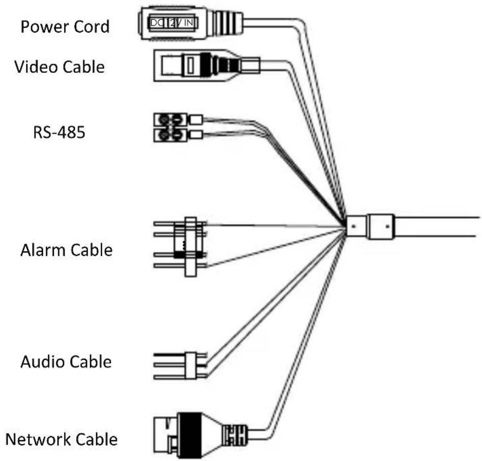
Figure 1-1 Cables of PTZ Camera
● Power Cord: Supports 12 VDC power supply.
● Video Cable: Connect BNC Cable to test the video output.
- Alarm Cable: Connect terminal ALARM-IN with GND interface, and connect terminal ALARM-OUT with ALARM-COM interface.
● Audio Cable: Connect terminal AUDIO-IN with GND interface.
● Network Cable: Connect the network interface with network cable.
1.3 Alarm Output
Alarm output is shown in Figure 1-2.
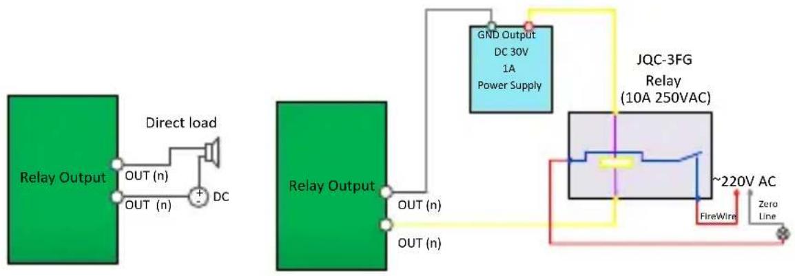
flowchart
graph TD
    A["Relay Output"] -->|OUT (n)| B["DC"]
    B --> C["Direct load"]
    C --> D["OUT (n)"]
    D --> E["Relay Output"]
    E --> F["OUT (n)"]
    F --> G["OUT (n)"]
    G --> H["GND Output DC 30V 1A Power Supply"]
    H --> I["JQC-3FG Relay (10A 250VAC)"]
    I --> J["FireWire"]
    I --> K["Zero Line"]
    style A fill:#99CCFF
    style E fill:#99CCFF
    style I fill:#FFD700
    style J fill:#FFA500
    style K fill:#FFA500
Figure 1-2 Alarm Output
2 Installaon
Before you start:
Check the package contents and make sure that the device in the package is in good condition and all the assembly parts are included.
Notes:
- Do not drag the PTZ camera with its waterproof cables; otherwise the waterproof performance is aected.
- Do not touch the bubble directly by hand. The image blurs otherwise.
- Do not power up the camera until the installaon is nished. To ensure the safety of personnel and equipment, all the installaon steps should be done with power supply o.
2.1 Installing the Memory Card
You can install the memory card for local storage.
2.1.1 PTZIP2XX Series PTZ Camera
Steps:
- Open the cover with the straight screwdriver from a crack on the cover, as shown in Figure 2-1.
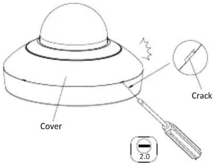
Figure 2-1 Open the Cover
- Unscrew the screws on the camera base with the cross screwdriver, and remove the bubble, as shown in Figure 2-2.
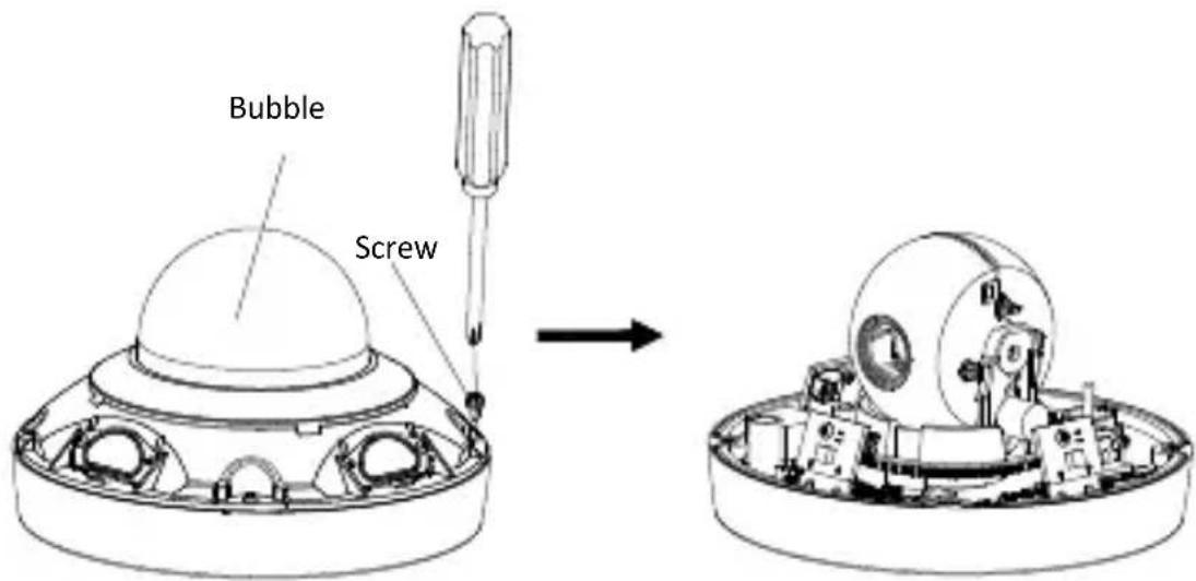
Figure 2-2 Remove the Bubble
-
Open the memory card slot in the camera, and insert the memory card.
-
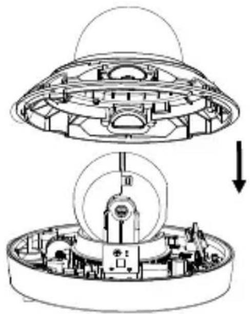
Align the bubble with the camera base, and install the bubble back. Fix the bubble with four M4×10 screws, as shown in Figure 2-3.
natural_image
Technical diagram of a spacecraft with internal components and a downward arrow indicating motion (no text or symbols present)Figure 2-3 Install the Bubble
- Align the cover with the camera, and install the cover back, as shown in Figure 2-4.
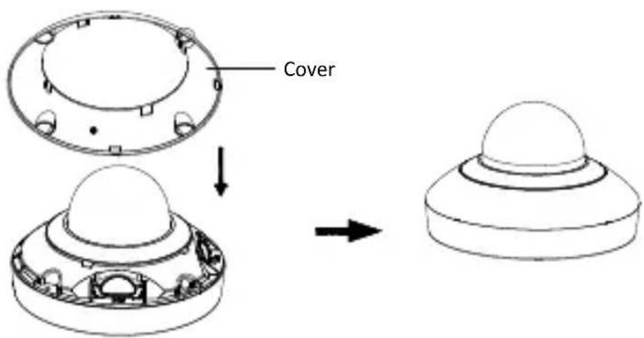
Figure 2-4 Install the Cover
2.1.2 PTZIP4XX Series PTZ Camera
Steps:
- Remove the four silicone plugs on the decorative rim as shown in Figure 2-5, and you can see four ange screws in the decorative rim.
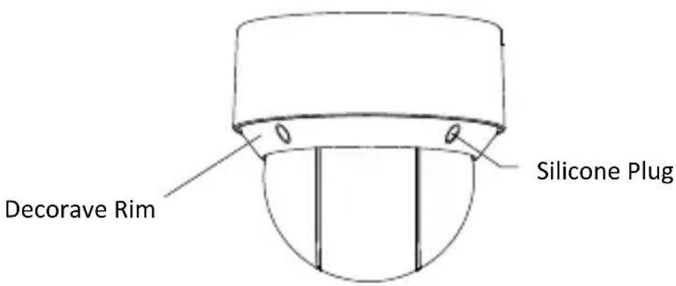
Figure 2-5 Remove the Silicone Plugs
- Loosen four ange screws with a screwdriver. Remove the bubble and the decorative rim as shown in Figure 2-6.
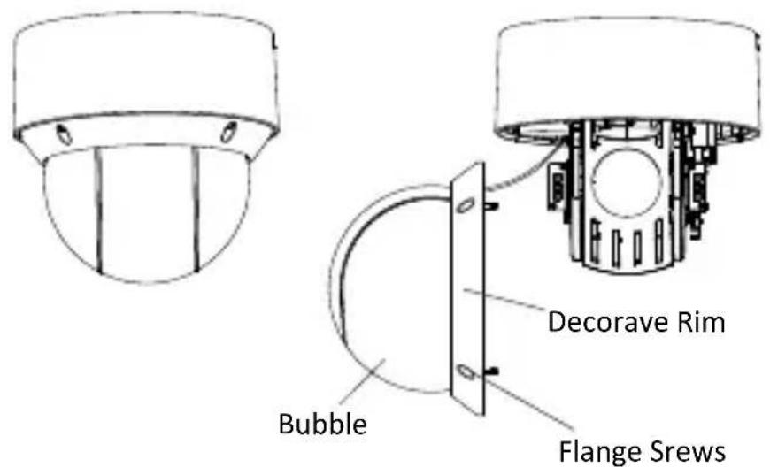
Figure 2-6 Remove the Bubble and the Decorave Rim
- Open the memory card cover and insert the memory card into the card slot as shown in Figure 2-7 and Figure 2-8.
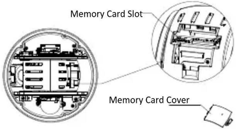
Figure 2-7 For 20× Camera Module
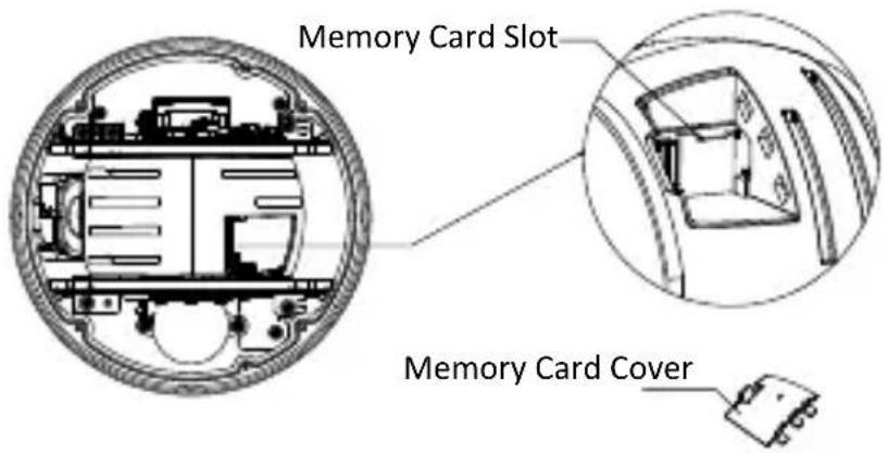
Figure 2-8 For 4× Camera Module
- Close the memory card cover. Fix the four ange screws and push four silicone plugs back to assemble the PTZ camera.
2.2 Installing PTZIP2XX Series PTZ Camera
2.2.1 Ceiling Mounng
Notes:
● The thickness of the ceiling shall range from 5 mm to 40 mm.
● Make sure the ceiling is strong enough to withstand more than four mes the weight of the PTZ camera and its accessories.
Steps:
- Rotate the installaon plate anclockwise, and remove the installaon plate, as shown in Figure 2-9.
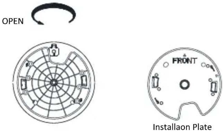
Figure 2-9 Remove the Installaon Plate
- Drill four screw holes in the ceiling according to the installaon plate.
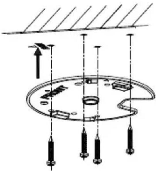
- Align the installaon plate with the screw holes, and x the installaon plate on the ceiling.
natural_image
Diagram of a mechanical assembly with pulleys and a central circular component, no text or symbols presentFigure 2-10 Fix the Installaon Plate
- Route the cables from the cable hole in the installaon plate.
- Align the camera with the installaon plate, and rotate the camera clockwise to x it, as shown in Figure 2-11.
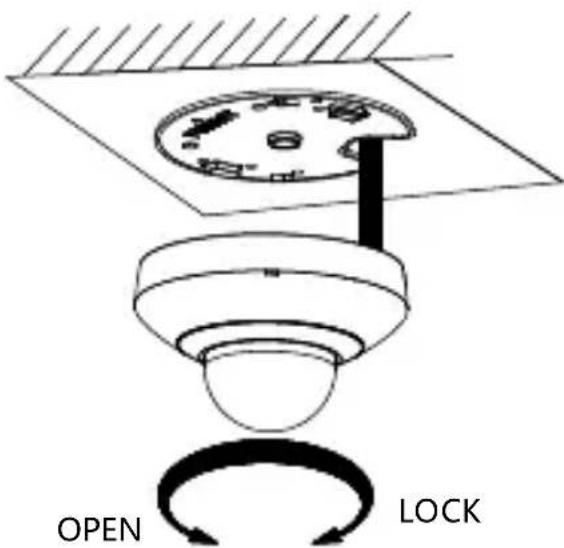
Figure 2-11 Fix the Camera
2.2.2 Wall Mounng
Notes:
- For cement wall, you need to use the expansion screw to x the bracket. The mounng hole of the expansion pipe on the wall should align with the mounng hole on the bracket.
- For wooden wall, you can just use the self-tapping screw to x the bracket.
● Make sure that the wall is strong enough to withstand more than eight mes the weight of the PTZ camera and its accessories.
Steps:
- Remove the installaon plate, and install it on the wall mounng bracket (not supplied) with two PM4×10screws.
Note:
Refer to step 1 in secon 2.2.1 Ceiling Mounng to remove the installaon plate.
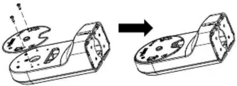
natural_image
Diagram showing a mechanical assembly before and after transformation, with no visible text or symbols.Figure 2-12 Install the Installaon Plate
- Loosen the xing screw on the bracket and remove the bracket base.
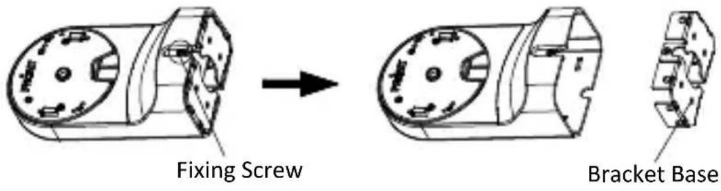
Figure 2-13 Remove the Bracket Base
- Install the bracket base on the wall with four PA4×25 screws.
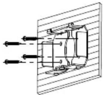
natural_image
Pure mechanical assembly diagram without any text, numbers, or symbolsFigure 2-14 Install the Bracket Base
- Route the cables. Align the camera with the installaon plate on the wall mounng bracket, and rotate the camera clockwise to x it on the bracket.
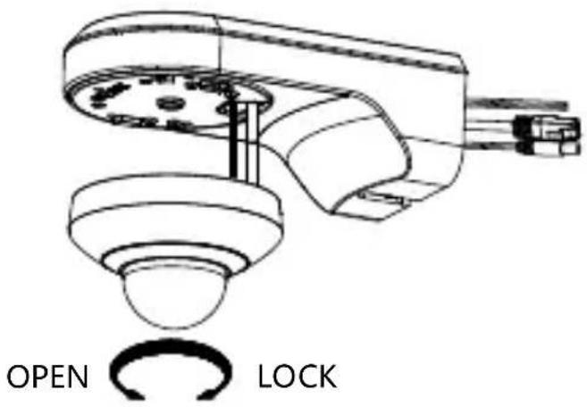
Figure 2-15 Install the Camera
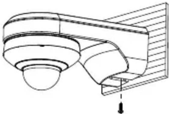
- Connect the cables. Install the wall moung bracket to the bracket base on the wall, and x it with the supplied PM4×10 screw.
natural_image
Technical line drawing of a mechanical component or housing assembly (no text or symbols)Figure 2-16 Fix the Bracket
- Remove the protecve Im aer installaon.
2.3 Installing PTZIP4XX Series PTZ Camera
PTZIP4XX series (IR) PTZ camera supports ceiling moung and in-ceiling moung.
Note:
Wall moung, pendant moung, and installaon with juncon box are supported for PTZIP4XX series (IR) PTZ camera. The corresponding accessories shall be purchased separately.
2.3.1 Ceiling Mounng
Purpose:
There are two ceiling mounng types provided for the camera, and we take the mounng without the juncon box as the example.
Notes:
● The ceiling moung is applicable to the indoor/outdoor solid ceiling construcon. The followings are the mandatory precondition for ceiling moung:
● The thickness of the ceiling shall range from 5 mm to 40 mm.
● Make sure the ceiling is strong enough to withstand more than four mes the weight of the PTZ camera and its accessories.
Wiring
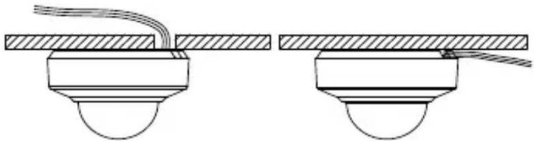
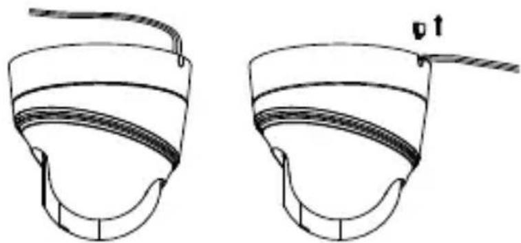
The cables of PTZ camera can be routed either from the top or the side of the back box, as shown in Figure 2-17 and Figure 2-18.
For the cables routed from the top of the back box, it is required to drill a cable hole in the ceiling.
natural_image
Technical line drawing of two mechanical assembly configurations with no visible text or symbolsFigure 2-17 Cabling for PTZIP4XX Series PTZ Camera
natural_image
Two identical line drawings of a helmet with a handle, shown from different angles (no text or symbols)Figure 2-18 Cabling for DE PTZIP4XX Series (IR) PTZ Camera
Ceiling Mounng without Juncon Box
- Rotate the base plate counterclockwise to separate it from the PTZ camera, as shown in Figure 2-19 and Figure 2-20.
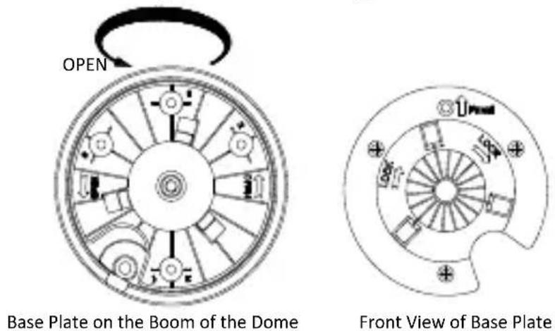
Figure 2-19 Base Plate for PTZIP4XX Series PTZ Camera
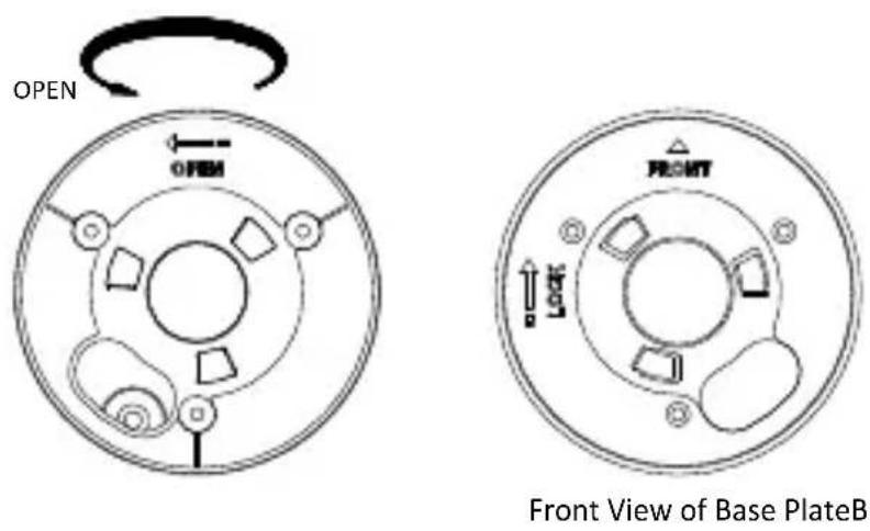
Figure 2-20 Base Plate for PTZIP4XX Series (IR) PTZ Camera
- Aach the drill template (supplied) to the place where you want to x the PTZ camera, and make sure the front arrow appoints to the monitoring area.
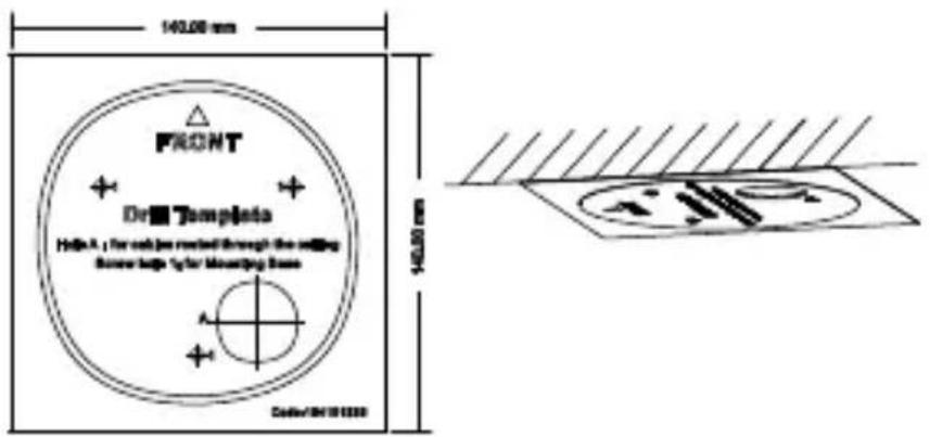
Figure 2-21 Aach the Drill Template
- Drill a cable hole in the ceiling according to the circle A on the template if you want to route the cables through the ceiling. Pull out the cable slot cover if you want to route the cables on the surface of the ceiling, as shown in Figure 2-22.
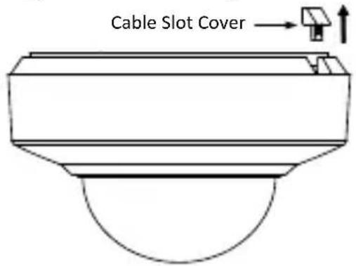
Figure 2-22 For PTZIP4XX Series PTZ Camera
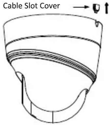
Figure 2-23 For PTZIP4XX Series (IR) PTZ Camera
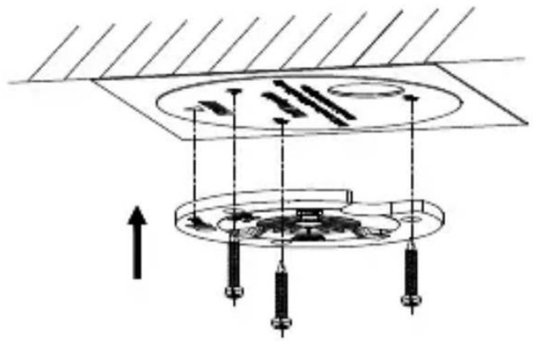
- Aach the base plate to the ceiling and secure it with the supplied three self-tapping screws by aligning with three screw holes in the ceiling, and the front arrows on the drill template and base plate should be aligned together as well, as shown in Figure 2-24 and Figure 2-25.
natural_image
Pure technical diagram of a mechanical assembly with no text, numbers, or symbolsFigure 2-24 For PTZIP4XX Series PTZ Camera
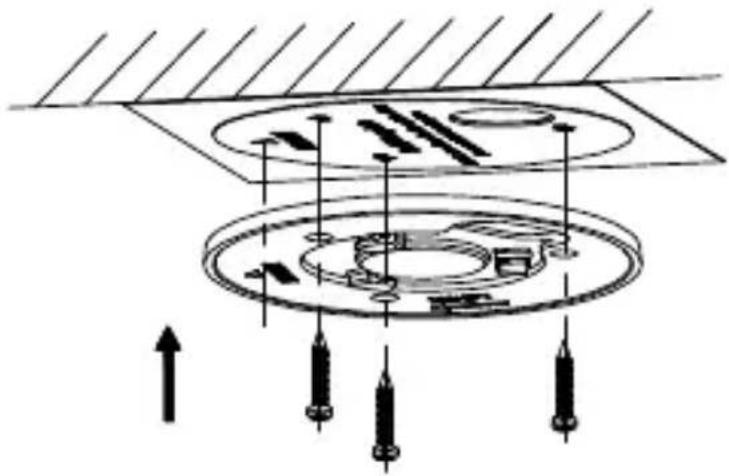
natural_image
Pure technical diagram of a mechanical assembly with concentric circles and directional arrows, no text or symbols present.Figure 2-25 For PTZIP4XX Series (IR) PTZ Camera
- Route the cables through the cable hole.
- Align the PTZ camera with the base plate. Rotate the PTZ camera clockwise into the base plate, and the PTZ camera is secured with the base plate by three locks on the plate.
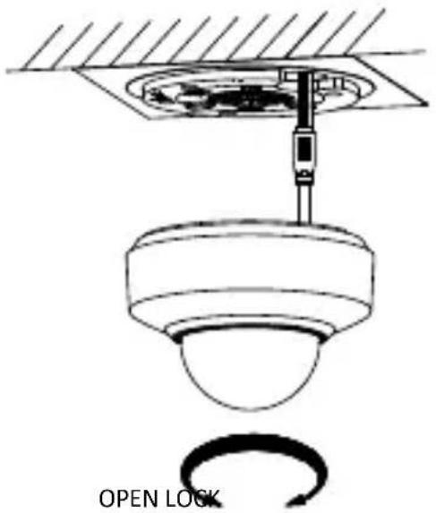
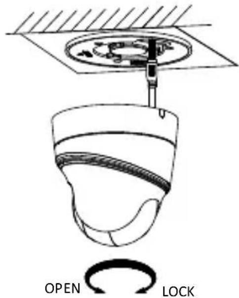
Figure 2-26 Secure the PTZ Camera
Note:
Aer PTZIP4XX series (IR) PTZ camera is installed, ghten the xing screw with a screwdriver as shown in Figure 2-27.
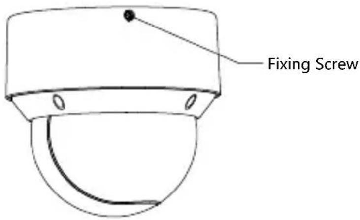
Figure 2-27 Tighten the Fixing Screw
2.3.2 In-ceiling Mounng
Notes:
- Reserve at least 250 mm of height for in-ceiling mounng.
● The thickness of the ceiling shall range from 5 mm to 40 mm.
● Make sure the ceiling is strong enough to withstand more than four mes the weight of the PTZ camera and its accessories
Steps:
- Rotate the base plate counterclockwise to separate it from the PTZ camera, as shown in Figure 2-28.
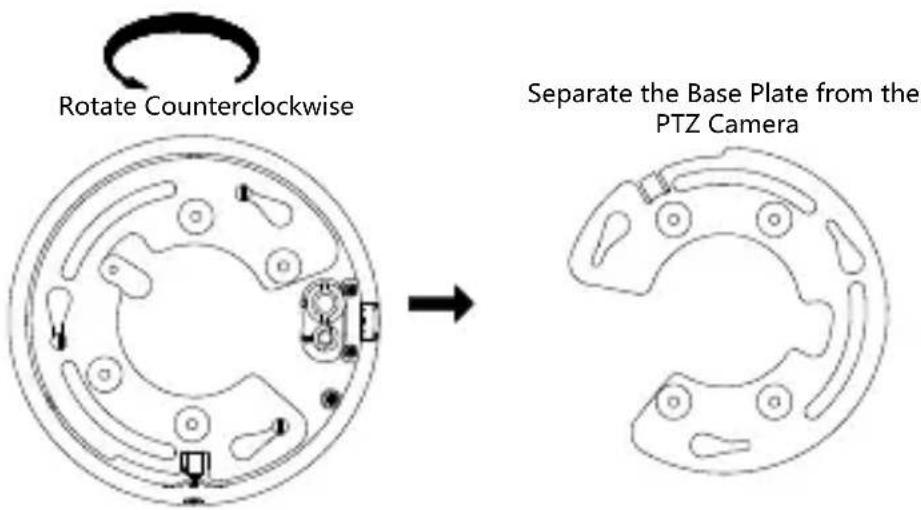
Figure 2-28 Separate the Base Plate from the PTZ camera
- Aach the drill template (supplied) to the place where you want to x the PTZ camera, and drill a hole in the ceiling according to the template.

Figure 2-29 Drill Template
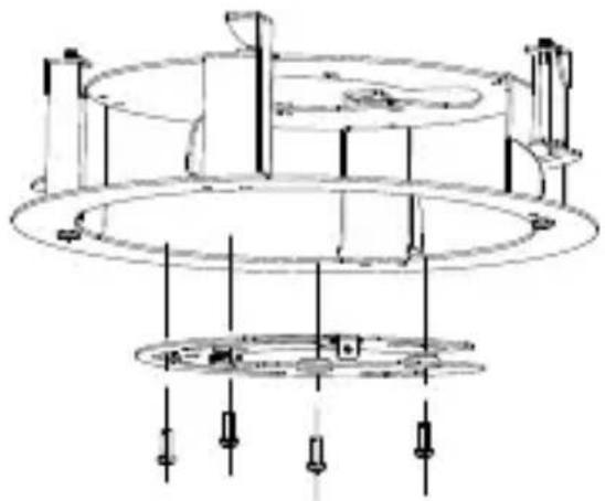
- Align the cable holes of the base plate to the cable holes of the in-ceiling bracket and then x the base plate onto the bracket with the four screws in the package (supplied), as shown in Figure 2-30.
natural_image
Technical line drawing of a mechanical assembly with concentric circular components and supporting elements (no text or symbols)Figure 2-30 Fix the Base Plate to In-ceiling Bracket
- Connect the cables and route the cables through the cable hole.
- Align the PTZ camera with the base plate. Rotate the PTZ camera clockwise into the base plate, and the PTZ camera is secured with the base plate by three locks on the plate.
- Fix the screws on the side with a screwdriver, as shown in Figure 2-31.
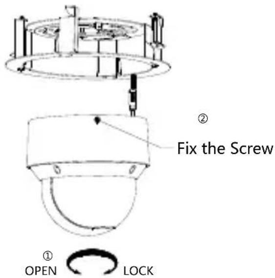
Figure 2-31 Fix the Camera
- Place the camera and the bracket into the hole drilled in step 2, and rotate the screws clockwise to x the camera.
- Fix the decorave rim with the bubble and the decorave rim will be aached to the in-ceiling bracket automacally, as shown in Figure 2-32.
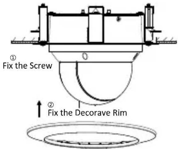
Figure 2-32 Assemble the Decorave Rim
3 Seng the PTZ Camera over the LAN
Notes:
- You shall acknowledge that the use of the product with Internet access might be under network security risks. For avoidance of any network aacks and informaon leakage, strengthen your own protecon. If the product does not work properly, contact with your dealer or the nearest service center.
- To ensure network security of the network PTZ camera, we recommend you to have the camera assessed and maintained termly. You can contact us if you need such service.
3.1 Wiring
To view and congregate the network PTZ camera via LAN (Local Area Network), you need to connect the network PTZ camera in the same subnet with your PC. Then, install the IP PORTAL or client soware to search and change the IP address of network PTZ camera.
Connect the camera to network according to the following gures.
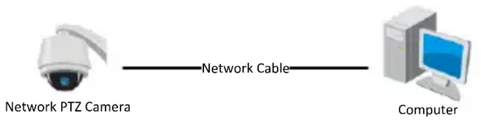
flowchart
graph LR
    A["Network PTZ Camera"] -->|Network Cable| B["Computer"]
Figure 3-1 Connecng Directly
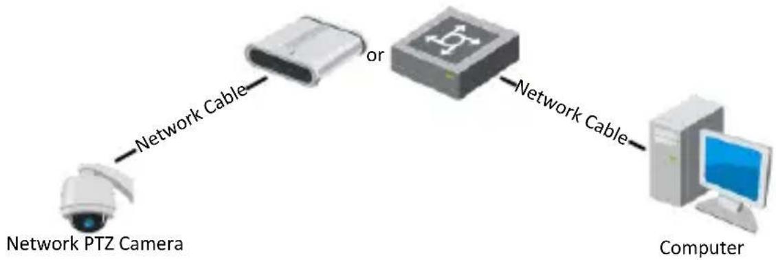
flowchart
graph LR
    A["Network PTZ Camera"] -->|Network Cable| B["Switch"]
    B -->|or| C["Computer"]
    C -->|Network Cable| B
Figure 3-2 Connecng via a Switch or a Router
3.2 Acvang the Camera
Purpose:
You are required to acvate the camera rst by seng a strong password for it before you can use the camera.
Acvaon via web browser, acvaon via IP PORTAL, and acvaon via client soware are supported. We will take acvaon via IP PORTAL soware and acvaon via web browser as examples to introduce the camera acvaon.
Note:
For the details of acvaon via client soware, refer to the user manual of the network camera.
3.2.1 Acvaon via Web Browser
Steps:
- Power on the camera. Connect the camera to your computer or the switch/router which your computer connects to.
- Input the IP address into the address bar of the web browser, and enter the acvaon interface.
Notes:
● The default IP address of the camera is 192.0.0.64.
- The computer and the camera should belong to the same subnet.
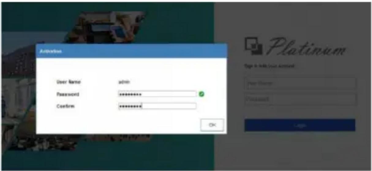
Figure 3-3 Acvaon Interface (Web)
- Create a password and input the password into the password eld.

STRONG PASSWORD RECOMMENDED— We highly recommend you create a strong password of your own choosing (using a minimum of 8 characters, including at least three of the following categories: upper case leers, lower case leers, numbers, and special characters) in order to increase the security of your product. And we recommend you reset your password regularly, especially in the high security system, reseng the password monthly or weekly can beer protect your product.
-
Conrm the password.
-
Click OK to acvate the camera and enter the live view interface.
3.2.2 Acvaon via IP PORTAL Soware
IP PORTAL soware is used for detectng the online device, acvang the device, and reseng the password.
Get the IP PORTAL soware from the supplied disk or the ocial website, and install the IP PORTAL according to the prompts.
Follow the steps to acvate the camera.
Steps:
- Run the IP PORTAL soware to search the online devices.
- Check the device status from the device list, and select an inactive device.
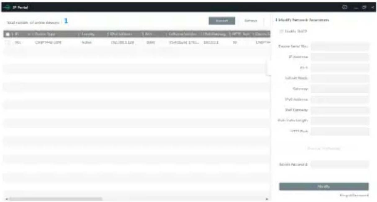
Figure 3-4 IP PORTAL Interface
Note:
The IP PORTAL soware supports acvang the camera in batch. Refer to the user manual of IP PORTAL soware for details.
- Create a password and input the password in the password eld, and conrm the password.

STRONG PASSWORD RECOMMENDED— We highly
recommend you create a strong password of your own choosing (using a minimum of 8 characters, including at least three of the following categories: upper case leers, lower case leers, numbers, and special characters) in order to increase the security of your product. And we recommend you reset your password regularly, especially in the high security system, reseng the password monthly or weekly can beer protect your product.
- Click Acvate to save the password.
Note:
You can check whether the acvaon is completed on the popup window. If acvaon failed, make sure that the password meets the requirement and try again.
3.3 Modifying the IP Address
Purpose:
To view and congregate the camera via LAN (Local Area Network), you need to connect the network camera in the same subnet with your PC.
Use the IP PORTAL soware or client soware to search and change the IP address of the device. We take modifying the IP Address via IP
PORTAL soware as an example to introduce the IP address modicaon.
Note:
For IP address modicaon via client soware, refer to the user manual of client soware.
Steps:
- Run the IP PORTAL soware.
- Select an acve device.
- Change the device IP address to the same subnet with your computer by either modifying the IP address manually or checking the Enable DHCP checkbox.
I Modify Network Parameters
Enable DHCP
Device Serial No.: CMIP7442-28M2016042688WR59
IP Address: 192.0.0.64
Port: 8000
Subnet Mask: 255.255.255.0
Gateway: 192.0.0.1
IPv6 Address:
IPv6 Gateway:
IPv6 Prefix Length: 0
HTTP Port 80
Security Verification
Admin Password:
Modify
Figure 3-5 Modify the IP Address
- Input the admin password and click Modify to acvate your IP address modicaon. The batch IP address modicaon is supported by IP PORTAL. Refer to the user manual of IP PORTAL for details.
4 Accessing via Web Browser
System Requirement:
Operang System: Microso Windows XP SP1 and above
version/Vista/Win7/Server 2003/Server 2008 32bits
CPU: Intel Penum IV 3.0 GHz or higher
RAM: 1G or higher
Display: 1024 × 768 resoluon or higher
Web Browser: Internet Explorer 8.0 and above version, Apple Safari
5.02 and above version, Mozilla Firefox 5 and above version and
Google Chrome 18 and above version
Steps:
-
Open the web browser.
-
In the browser address bar, input the IP address of the network PTZ camera, and enter the login interface.
Note:
The default IP address is 192.0.0.64. You are recommended to change the IP address to the same subnet with your computer.
- Input the user name and password.
The admin user should congregate the device accounts and user/operator permissions properly. Delete the unnecessary accounts and user/operator permissions.
Note:
The device IP address gets locked if the admin user performs 7 failed password aempts (5 aempts for the user/operator).
4. Click Login.

Sign in with your account
User Name
Password
Login
Figure 4-1 Login Interface
- Install the plug-in before viewing the live video and managing the network PTZ camera. Follow the installaon prompts to install the plug-in.
Note:
You may have to close the web browser to nish the installaon of the plug-in.
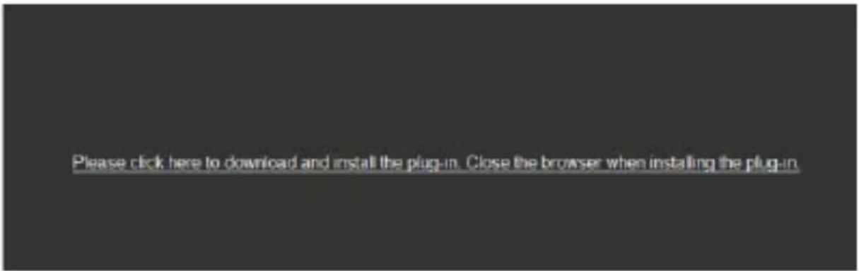
Figure 4-2 Download Plug-in
- Reopen the web browser aer the installaon of the plug-in and repeat the above steps 2-4 to login.
Note:
For detailed instrucons of further conguraon, refer to the user manual of the network camera.
- Legal Disclaimer
- Regulatory Informaon
- FCC Informaon
- FCC Conditions
- EU Conformity Statement
- Industry Canada ICES-003 Compliance
- Safety Instrucon
- Warnings
- Cauons
- Table of Contents
- Overview....9
- Installation 12
- Setting the PTZ Camera over the LAN 31
- Accessing via Web Browser 38
- Overview
- Introducon
- Cable Descripons
- Notes:
- Alarm Output
- Installaon
- Before you start:
- Installing the Memory Card
- PTZIP2XX Series PTZ Camera
- Steps:
- PTZIP4XX Series PTZ Camera
- Installing PTZIP2XX Series PTZ Camera
- Ceiling Mounng
- Wall Mounng
- Note:
- Installing PTZIP4XX Series PTZ Camera
- Ceiling Mounng
- Purpose:
- Wiring
- Ceiling Mounng without Juncon Box
- In-ceiling Mounng
- Seng the PTZ Camera over the LAN
- Wiring
- Acvang the Camera
- Acvaon via Web Browser
- Acvaon via IP PORTAL Soware
- STRONG PASSWORD RECOMMENDED— We highly
- Modifying the IP Address
- Accessing via Web Browser
- System Requirement:
- Click Login.
Brand : LTS
Model : PTZIP412X15WIR
Category : Surveillance Camera