LT-4GPOEW1 - Router LTS - Free user manual and instructions
Find the device manual for free LT-4GPOEW1 LTS in PDF.

User questions about LT-4GPOEW1 LTS
0 question about this device. Answer the ones you know or ask your own.
Ask a new question about this device
Download the instructions for your Router in PDF format for free! Find your manual LT-4GPOEW1 - LTS and take your electronic device back in hand. On this page are published all the documents necessary for the use of your device. LT-4GPOEW1 by LTS.
USER MANUAL LT-4GPOEW1 LTS
Industrial Router Pro Series
LT-4GPOEW1
Quick Start Guide
Welcome
Thank you for choosing LTS Industrial LT-4GPOEW1 industrial cellular router.
This guide describes how to install the LT-4GPOEW1 and how to log in the Web GUI to configure the device. Once you complete the installation, refer to the LTS Industrial LT-4GPOEW1 User Guide for instructions on how to perform configurations on the device.
Related Documents
This Start Guide only explains the installation of LTS Industrial LT-4GPOEW1 router. For more functionality and advanced settings, please refer to the relevant documents as below.
| Document | Description |
| LT-4GPOEW1 Datasheet | Datasheet for LT-4GPOEW1 industrial cellular router. |
| LT-4GPOEW1 User Guide | Users could refer to the guide for instruction on how to log in the web GUI, and how to configure all the settings. |
The related documents are available on LTS Industrial website: www.LTsecurityinc.com.au
Declaration of Conformity
LT-4GPOEW1 are in conformity with the essential requirements and other relevant provisions of the CE, FCC, and RoHS.

text_image
CE FC RoHS
text_image
Get HelpFor assistance, please contact
LTS Industrial technical support:
Email: service@LTsecurityinc.com.au
Tel: 02 9135 8750
Revision History
| Date | Doc Version | Description |
| Apr. 26, 2019 | V 1.0 | Initial version |
| May 11, 2020 | V 1.1 | Web interfaces upgrade |
| Nov. 25, 2020 | V 2.0 | Layout Replace |
1. Packing List
Before you begin to install the LT-4GPOEW1 router, please check the package contents to verify that you have received the items below.

1 × LT-4GPOEW1

1 × Ethernet Cable
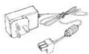
1 × Power Adapter

2 × Magnetic Cellular Antennas
1 × 6-Pin Pluggable Terminal

1 × DIN Rail Kit

4 × Setscrews

1 × Warranty Card

1 × Quick Start Guide

1 × Stubby Wi-Fi Antenna (Wi-Fi Version Only)

1 × GPS Antenna (GPS Version Only)

2 × Stubby Cellular Antennas (Optional)

If any of the above items is missing or damaged, please contact your sales representative.
2. Hardware Introduction
2.1 Overview

text_image
MAIN GPS/WIFI AUX UR32 POWER SYSTEM SIM MIN/Min-SD LAN 1/WIN LAN 2 ① ② ③ ④ ⑤ ⑥ ⑦ ⑧① Main Cellular Antenna Connector
② GPS/WIFI Antenna Connector
③ AUX Cellular Antenna
④ LED Indicator Area
POWER: Power Indicator
SYSTEM: Status Indicator
SIM : Status Indicator
Y: Signal Strength Indicator
⑤ Serial Port & I/O
⑥ Ethernet LAN1/WAN Port
⑦ Ethernet LAN2 Port
⑧ Power Connector
⑨ SIM and Reset Button Holder
2.2 Dimensions (mm)

text_image
90 82 108 90 26 4-Ø 3.6
text_image
28.52.3 Connectors

| PIN | RS232 | RS485* | DI | DO | Description |
| 1 | --- | --- | --- | OUT | Digital Output |
| 2 | --- | --- | IN | --- | Digital Input |
| 3 | GND | --- | --- | --- | Ground |
| 4 | --- | --- | COM | COM | Common Ground |
| 5 | RXD | B | --- | --- | Receive Data |
| 6 | TXD | A | --- | --- | Transmit Data |
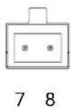
| PIN | Description |
| 7 | Positive |
| 8 | Negative |
*: Only for -485 model.
2.4 LED Indicators
| LED | Indication | Status | Description |
| POWER Power Status | Off The power is switched off | ||
| On The power is switched on | |||
| SYSTEM System Status | Green Light | Static: Start-up | |
| Blinking slowly: the system is running properly | |||
| Red Light | The system goes wrong | ||
| SIM SIM Card Status | Off | SIM1 or SIM2 is registering or fails to register (or there are no SIM cards inserted) | |
| Green Light | Blinking slowly: SIM1 has been registered and is ready for dial-up | ||
| Blinking rapidly: SIM1 has been registered and is dialing up now | |||
| Static: SIM1 has been registered and dialed up successfully | |||
| Orange Light | Blinking slowly: SIM2 has been registered and is ready for dial-up | ||
| Blinking rapidly: SIM2 has been registered and is dialing up now | |||
| Static: SIM2 has been registered and dialed up successfully | |||
| Signal Strength | Signal 1/2/3 | Off | No signal |
| Green Light | Static/Off/Off: weak signals with 1-10 ASU (please check if the antenna is installed correctly, or move the antenna to a suitable location to get better signal) | ||
| Static/Static/Off: normal signals with 11-20 ASU | |||
| (average signal strength) | |||
| Static/Static/Static: strong signals with 21-31 ASU (signal is good) | |||
2.5 Reset Button
Reset button is under the SIM slots.
| Function | Description | |
| SYSTEM LED | Action | |
| Reset | Blinking | Press and hold the reset button for more than 5 seconds. |
| Static Green → Rapidly Blinking | Release the button and wait. | |
| Off → Blinking | The router is now reset to factory defaults. | |
2.6 Ethernet Port Indicator
| Indicator | Status | Description |
| Link Indicator (Orange) | On Connected | |
| Blinking | Transmitting data | |
| Off | Disconnected |
3. Hardware Installation
Environmental Requirements
- Power Input: 9-48 VDC
- Power Consumption: Typical 1.9W (Max 2.4 W)
- Operating Temperature: -40°C to 70°C (-40°F -158°F)
- Relative Humidity: 0% to 95% (non-condensing) at 25°C/77°F
3.1 SIM Card/Micro SD Card Installation
A. Unscrew the cover of the SIM card then screw it up.

natural_image
Line drawing of a rectangular electronic device housing with internal compartments and mounting feet (no text or symbols)B. Put SIM card/Micro SD into the slot and take it off.

natural_image
Technical line drawing of a mechanical device with internal components and mounting bracket (no text or symbols)3.2 Antenna Installation
Rotate the antenna into the antenna connector accordingly.
The external antenna should be installed vertically always on a site with a good signal.

natural_image
Line drawing of two electronic devices connected by a cable, showing internal components and signal flow arrows (no text or symbols)3.4 Router Installation
The router can be placed on a desktop or mounted to a wall or a DIN rail.
3.4.1 Wall Mounting (Measured in mm)
Use 4 pcs of M3 × 6 flat head Phillips screws to fix the router on the wall.

Recommended torque for mounting is 1.0 N·m, and the maximum allowed is 1.2 N·m.

natural_image
Technical line drawing of a mechanical component with springs and bolts (no text or symbols)3.4.2 DIN Rail Mounting (Measured in mm)
Use 2 pcs of M3 × 6 flat head Phillips screws to fix the mount clip to the router, and then hang the device to the DIN rail. The width of DIN rail is 3.5 cm.

Recommended torque for mounting is 1.0 N·m, and the maximum allowed is 1.2 N·m.

natural_image
Technical line drawing of a mechanical housing or enclosure with mounting holes and a central panel (no text or symbols)
natural_image
Technical line drawing of a mechanical enclosure or housing with mounting holes and internal components (no text or symbols)4. Log in the Web GUI of Router
4.1 PC Configuration
Please connect PC to LAN port of LT-4GPOEW1 router. PC can obtain an IP address, or you can configure a static IP address manually. The following steps are based on Windows 10 operating system for your reference.
(Note: As remote access is disabled by default, you can't access to the router's Web GUI if you connect PC to WAN port of the router. But it will function properly if you enable it on Web GUI.)
text_image
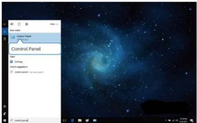
Control Panel Options Settings Search suggestions control panel: 10x 8x 6x 5x 4x 3x 2x 1x 0x control panel① Click "Search Box" to search "Control Panel" on the Windows 10 taskbar.
text_image
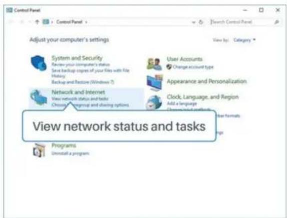
Control Panel Adjust your computer's settings View by: Category System and Security Review your computer's status Save backup copies of your files with file History Backup and Restore (Windows 7) User Accounts Change account type Appearance and Personalization Network and Internet View network status and tasks Choose group and closing options Clock, Language, and Region Add a language Change and other categories User formats View network status and tasks Programs Uninstall a program② Click "Control Panel" to open it, and then click
"View network status and tasks".
text_image
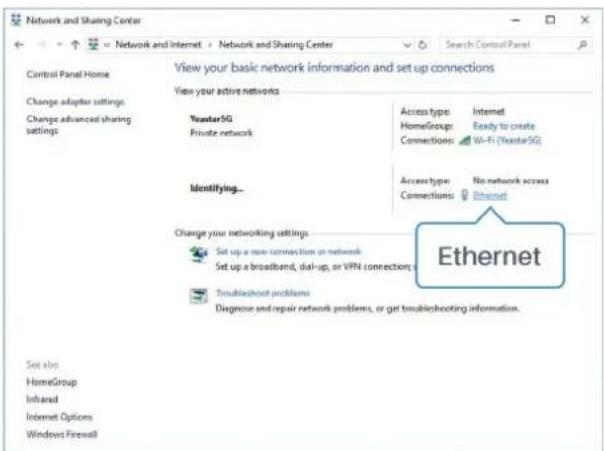
Network and Sharing Center Control Panel Home Change adapter settings Change advanced sharing settings View your basic network information and set up connections View your active networks YuantarSG Private network Access type: Internet HomeGroup: Ready to create Connections: Wi-Fi (YuantarSG) Identifying... Access type: No network access Connections: Ethernet Change your networking settings Set up a new connection or network Set up a broadband, dial-up, or VPN connections Ethernet Troubleshoot problems Diagnose and repair network problems, or get troubleshooting information. See also HomeGroup Inhand Internet Options Windows Firewall③ Click "Ethernet" (May have different names).

text_image
Ethernet Status General Connection IPv4 Connectivity: No network access IPv6 Connectivity: No network access Media State: Enabled Durations: 09:01:21 Speed: 1.0 Gbps Details... Activity Properties Received 210 0 Properties Enable Diagnose Close④ Click "Properties".
text_image
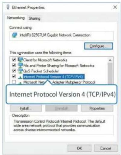
Ethernet Properties Networking Sharing Connect using: Intel(R) 82567LM Gigabit Network Connection Configure... This connection uses the following items: Client for Microsoft Networks File and Printer Sharing for Microsoft Networks GoS Packet Scheduler Internet Protocol Version 4 (TCP/IPv4) Microsoft Net Adapter Multiplexor Protocol Internet Protocol Version 4 (TCP/IPv4) Install... Uninstall Properties Description Transmission Control Protocol/Internet Protocol. The default wide area network protocol that provides communication across diverse interconnected networks. OK Cancel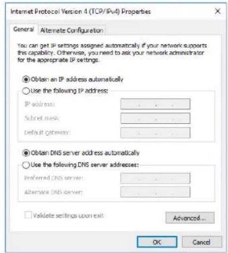
text_image
Internet Protocol Version 4 (TCP/IPv4) Properties General Alternate Configuration You can get IP settings assigned automatically if your network supports this capability. Otherwise, you need to ask your network administrator for the appropriate IP settings. Obtain an IP address automatically Use the following IP address: IP address: ... Subset mask: ... Default gateway: ... Obtain DNS server address automatically Use the following DNS server addresses: Preferred DNS server: ... Alternate DNS server: ... Validate settings upon exit Advanced... OK Cancel
text_image
Internet Protocol Version 4 (TCP/IPv4) Properties Genera You can get IP settings assigned this capability. Otherwise, you re for the appropriate IP settings. Obtain an IP address autom: Use the following IP address: IP address: 192 . 168 . 1 . 20 Subnet mask: 255 . 155 . 255 . 0 Default gateway: 192 . 168 . 1 . 1 Obtain DNS server address automatically Use the following DNS server addresses: Preferred DNS server: 192 . 168 . 1 . 1 Alternate DNS server: . Validate settings upon exit: 192 . 168 . 1 . 1 OK Cancel⑤ Double Click "Internet Protocol Version 4 (TCP/IPv4)" to configure IP address and DNS server.
⑥ Method 1: click "Obtain an IP address automatically";
Method 2: click "Use the following IP address" to assign a static IP manually within the same subnet of the router.
(Note: Remember to click "OK" to finish configuration.)
4.2 Log in the Router
If this is the first time you configure the router, please use the default settings below:
IP Address: 192.168.1.1
Username: admin
Password: password
A. Start a Web browser on your PC (Chrome is recommended), type in the IP address, and press Enter on your keyboard.
B. Enter the username and password, click "Login".

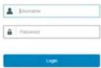

If you enter the username or password incorrectly more than 5 times, the login page will be locked for 10 minutes.
C. When you log in with the default username and password, you will be asked to modify the password. It's suggested that you change the password for the sake of security. Click "Cancel" button if you want to modify it later.
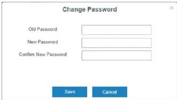
text_image
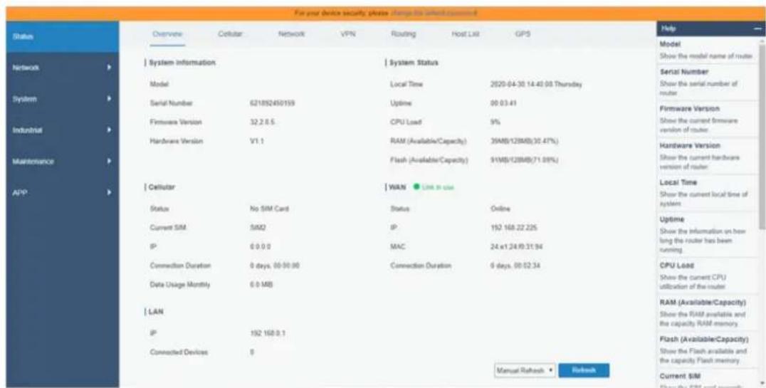
Change Password Old Password New Password Confirm New Password Save CancelD. After you log in the Web GUI, you can view system information and perform configuration on the router.
text_image
For your device security please change to which continued Status Overview Cellular Network VPN Routing Host List GPS Network System Information System Status Model Local Time 2020-04-30 14:45:00 Thursday Serial Number Show the serial number of router System Serial Number 621892450159 Uptime 00:03:41 Firmware Version Show the current firmware version of router. Industrial Hardware Version V1.1 CPU Load 9% Hardware Version Show the current hardware version of router Maintenance Cellular WALN Local Time Show the current local time of system Status No SIM Card Status Online Current SIM SIMQ IP 192.168.22.225 IP 6:0:0:0 MAC 24 x1.24 IP 31:94 Connection Duration 0 days, 00:00:00 Connection Duration 6 days, 00:02:34 Data Usage Monthly 6:0:MB LAN IP 192.168:0.1 Connected Devices 0 RAM Manual Refresh Refresh Current SIM5. Network Configuration
This chapter explains how to connect LT-4GPOEW1 to network via WAN connection or cellular.
5.1 Ethernet WAN Configuration
A. Go to "Network > Interface > Port" to change LAN1 to WAN port.
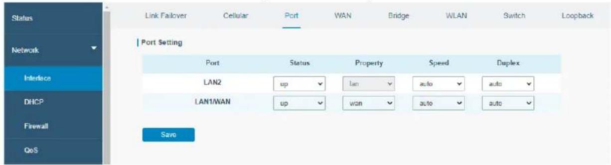
text_image
Link Failover Cellular Port WAN Bridge WLAN Switch Loopback Port Setting Port Status Property Speed Duplex LAN2 up lan auto auto LAN1/WAN up wan auto auto SaveB. Go to "Network > Interface > WAN" to configure WAN parameters. Take static IP configuration as an example. DHCP client and PPPoE type are optional according to your requirements.
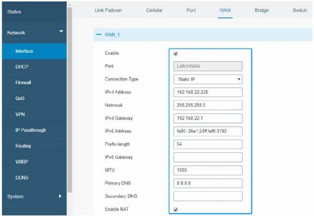
text_image
Status Link Failover Cellular Port WAN Bridge Switch Network WAN_1 Interface Enable Port LAN1/WAN Connection Type Static IP IPv4 Address 192.168.22.225 Netmask 255.255.255.0 IPv4 Gateway 192.168.22.1 IPv6 Address fe80::26e1:24ff:fe#0:3192 Prefix-length 64 IPv6 Gateway MTU 1500 Primary DNS 8.8.8.8 Secondary DNS Enable NATClick "Save & Apply" button to make the changes take effect.
C. Connect WAN port to another router or modem.
D. Log in LT-4GPOEW1 web GUI via WAN port IP address and go to "Status > Network" to check if status is "up".

text_image
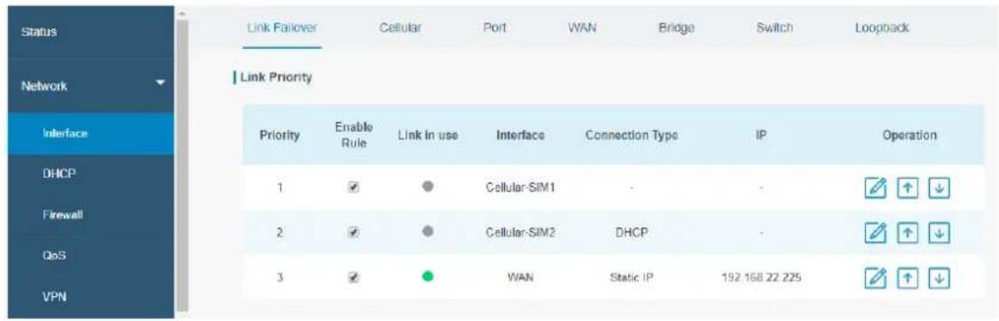
Status Overview Cellular Network VPN Routing Host List GPS Network | WAN-IPv4 Port Status Type IP Netmask Gateway DNS Connection Duration LAN1/WAN up Static 192.168.22.225 255.255.255.0 192.168.22.1 8.8.8.8 08h 22m 29s IndustrialE. Go to "Network > Interface > Link Failover" to rise the WAN priority to 1.

text_image
Status Network Interface DHCP Firewall QoS VPN Link Follower Cellular Port WAN Bridge Switch Loopback Link Priority Priority Enable Rule Link In use Interface Connection Type IP Operation 1 ✓ ● WAN Static IP 192.168.22.225 ✓ ↑ ↓ 2 ✓ ● Cellular-SIM1 DHCP - ✓ ↑ ↓ 3 ✓ ● Cellular-SIM2 - - ✓ ↑ ↓F. Open your preferred browser on PC, then type any available web address into address bar and see if it is able to visit Internet via LT-4GPOEW1 router.
5.2 Cellular Connection Configuration
Take inserting SIM card into SIM1 slot as an example; please refer to the following detailed operations.
A. Click "Network > Interface > Cellular > Cellular Setting" to configure the cellular info, like APN and network type.
B. Click "Save" and "Apply" for configuration to take effect.

text_image
Link Failover Cellular Port WAN Bridge Switch Loopback Cellular Settings SIM1 SIM2 APN Username Password PIN Code Access Number Authentication Type Auto Auto Network Type Auto Auto PPP Preferred SMS Center +8613800592500 +8613800592500 Enable NAT ✓ ✓ Roaming ✓ ✓ Data Limit 0 MB 0 MB Billing Day Day 1 of The Month Day 1 of The MonthIf you select "Auto", the router will obtain ISP information from SIM card to set APN, Username, and Password automatically. This option will only be taken effect when the SIM card is issued from a well-known ISP.
C. Go to "Network > Interface > Link Failover" to enable SIM1 and rise link priority of SIM1.
text_image
Status Link Failover Cellular Port WAN Bridge Switch Loopback Network Link Priority Interface Priority Enable Rule Link In use Interface Connection Type IP Operation DHCP 1 ✓ ● Cellular-SiM1 - - Firewall 2 ✓ ● Cellular-SiM2 DHCP - - QoS 3 ✓ ● WAN Static IP 192.168.22.225 VPND. Click to configure ICMP ping detection information.
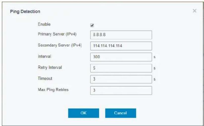
text_image
Ping Detection Enable Primary Server (IPv4) 8.8.8.8 Secondary Server (IPv4) 114.114.114.114 Interval 300 s Retry Interval 5 s Timeout 3 s Max Ping Retries 3 OK CancelE. Click "Status > Cellular" to view the status of the cellular connection. If it shows "Connected", it means SIM1 has dialed up successfully.
On the other hand, you can check the status of SIM indicator. If it keeps on green light statically, it means SIM1 has dialed up successfully.
| Overview | Cellular | Network | VPN | Routing | Host List | GPS |
| Modem | Network | |||||
| Status | Ready | Status | Connected | |||
| Model | IP Address | 10.2.25.74 | ||||
| Current SIM | SIM1 | Netmask | 255.255.255.240 | |||
| Signal Level | 29asu (-55dBm) | Gateway | 10.2.25.73 | |||
| Register Status | Registered (Home network) | DNS | 211.136.17.107 | |||
| IMEI | 861585042050250 | Connection Duration | 0 days, 00:00:34 | |||
| IMSI | 460045927703654 | Data Usage Monthly | ||||
| ICCID | 89860439101880723654 | SIM-1 | RX: 0.0 MIB TX: 0.0 MIB ALL: 0.0 MiB | |||
| ISP | CHINA MOBILE | |||||
| Network Type | FDD LTE | SIM-2 | RX: 0.0 MIB TX: 0.0 MIB ALL: 0.0 MiB | |||
| PLMN ID | 46000 | |||||
| LAC | 592f | |||||
| Cell ID | 271f848 | |||||
F. Open your preferred browser on PC, then type any available web address into address bar and see if it is able to visit Internet via LT-4GPOEW1 router.
[END]