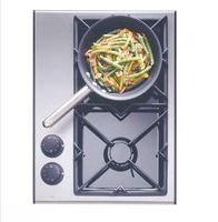
ZGW124ENSS - Hob GE - Free user manual and instructions
Find the device manual for free ZGW124ENSS GE in PDF.


| Product Type | Gas Cooktop Component |
| Brand | GE |
| Model | ZGW124ENSS |
| Dimensions (W x D x H) | 15-1/2 in x 21 in x 3-1/4 in |
| Cutout Width | 14-1/2 in |
| Cutout Depth | 19-1/2 in |
| Weight | Approx. 20 lbs |
| Fuel Type | Natural Gas (4 in water column pressure) |
| Gas Connection | 1/2 in NPT male |
| Electrical Requirements | 120 V, 60 Hz, 1.0 A |
| Ignition Type | Electronic Ignition |
| Number of Burners | 4 (2 per side, right hand controls) |
| Control Location | Right hand side |
| Modular System | Compatible with other Monogram component cooktops |
| LP Conversion | Not convertible to LP gas |
| Safety Features | Manual gas shut-off valve required; grounding required |
| Cleaning | Removable burner caps, grates, and knobs for easy cleaning |
| Included Accessories | Pressure regulator, joiner strip, clamping screws, chassis support brace |
| Warranty | Standard GE warranty (see manual for details) |
Frequently Asked Questions - ZGW124ENSS GE
User questions about ZGW124ENSS GE
0 question about this device. Answer the ones you know or ask your own.
Ask a new question about this device
Download the instructions for your Hob in PDF format for free! Find your manual ZGW124ENSS - GE and take your electronic device back in hand. On this page are published all the documents necessary for the use of your device. ZGW124ENSS by GE.
USER MANUAL ZGW124ENSS GE
Before you begin—Read these instructions completely and carefully.
IMPORTANT: Save these instructions for local inspector's use.
IMPORTANT: OBSERVE ALL GOVERNING CODES AND ORDINANCES.
NOTE TO INSTALLER: Be sure to leave these instructions with the Consumer.
NOTE TO CONSUMER: Keep these instructions with your Use and Care Book for future reference.
WARNING This appliance must be properly grounded. See “Electrical Supply”, page 13.
| If you have questions concerning the installation of this product, call the GE Answer Center® Consumer Information Service at 800.626.2000, 24 hours a day, 7 days a week. | If you received a damaged component, you should contact your dealer.Installation of these components require basic mechanical skills. Proper installation is the responsibility of the installer. |
| CAUTION: FOR PERSONAL SAFETY, REMOVE HOUSE FUSE OR CIRCUIT BREAKER BEFORE BEGINNING INSTALLATION.These appliances must be supplied with the proper voltage and frequency, as listed on page 18. Connect to an individual, properly grounded branch circuit breaker or time delay fuse. Proper electrical ratings should be verified with listing on product's rating plate.Wiring must conform to the requirements of the National Electrical Code. If the electric supply provided does not meet the specifications, call a licensed electrician.WARNING:Any home ventilation system, such as a cooktop with a downdraft mechanism, may interfere with the proper flow of exhaust products or combustion air required by gas furnaces, gas water heaters, fireplaces, or | other naturally vented systems. To minimize the chance of interference with such naturally vented systems, follow the heating equipment manufacturer's guidelines, and local codes.Also follow the guidelines in ASHRAE Standard 62-1989, "Ventilation for Acceptable Indoor Air Quality", section 5.8. When following these guidelines, be sure to test for proper airflow direction into the draft hood of a naturally vented gas furnace or water heater. This can be checked by striking a match, blowing it out, and while it is still smoking, holding it near the draft hood relief opening. If smoke is drawn into the opening, vent flow is in the proper direction. If the ASHRAE Standard 62 guidelines are not satisfied, a positive supply of outside air may have to be supplied.In the absence of local codes, the gas cooktop must comply with the National Fuel Gas Code, ANSI Z223.1, latest edition. |
| Models Available ....3Product Dimensions ....3, 4Installation Accessories....5Advance Planning ....5Installation Options ....5Installation Rules ....5Installation Location....6Tools & Materials Required ....7Cutout Information ....7, 8, 9Venting Options ....10Ductwork Advance Planning....10Optional Ductwork Arrangement ....10Determine Ductwork Location ....11 | Install Blower Assembly ....11Finalize Ductwork ....11Duct Fittings ....12Gas Supply Location ....13Electrical Supply ....13Step 1: Apply Gasket Strip ....14Step 2: Remove Knobs, Gates....14Step 3: Joining Multiple Cooktops ....14, 15, 16Step 4: Secure Cooktop(s) to Countertop....16Step 5: Connect Gas....17Step 6: Connect Electrical ....17, 18Electrical Power Requirements ....18Finalize Installation....19 |
Contents
Design Information
| Component Cooktop System | ||
| Models Available | Monogram Component Cooktop System offers cooking flexibility with modular cooktops in a variety of cooking technologies to meet any cooking need. | ZGW124EN3Gas Cooktop Component, with right hand controls |
| ZEW145VHalogen and Ribbon Component | ZGW125EN3Gas Cooktop Component, with left hand controls | |
| ZEW155NUpdraft Grill Cooktop Component, | JXBA55 blower motor assembly is supplied for the downdraft vent and downdraft grill.JXBC55 optional outdoor cover accessory may be ordered for installation of blower and motor assembly on an outside wall. | |
| ZEW166YDowndraft Grill Cooktop Component | ||
| ZEW176YDowndraft Vent Component | ||
| Product Dimensions | ZEW145VHalogen and Ribbon Component (240 and 208 volt, dual rated)Parts supplied:• 44" flexible conduit• One joiner strip• Two sets clamping screws• One chassis support brace | 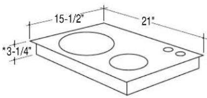 *Allow additional 1" depth for clearance of flexible conduit *Allow additional 1" depth for clearance of flexible conduit |
| ZEW155NUpdraft Grill Cooktop Component (240 volt)Parts supplied• Grease collection jar• 48" flexible conduit• One joiner strip• Two sets clamping screws• One chassis support brace |  | |
| ZEW176YDowndraft Vent ComponentInstall next to gas or halogen components.(Cannot be installed next to an updraft grill)(120 volt)Parts supplied:• 48" flexible conduit• Two downdraft joiner strips• One downdraft endcap• JXBA55 blower motor assemblyNOTE:The downdraft plenum is shipped with the discharge outlet on the left side. It can be changed to the right side. |  | |
Product Dimensions
ZEW166Y
Downdraft Grill Cooktop Component (240 volt)
Parts supplied:
- Grease collection jar
- 48" flexible conduit
• One set clamping screws
• One downdraft joiner strip
• JXBA55 blower motor assembly
NOTE: The downdraft plenum is shipped with the discharge outlet on the left side. It can be changed to the right side.


Front View, Downdraft Grill With Blower Motor Assembly Left Side View, Downdraft Grill
ZGW124EN3
Gas Cooktop Component, with right hand controls
ZGW125EN3
Gas Cooktop Component, with left hand controls
Parts supplied with each:
- 1/2" inlet pipe
- Pressure regulator
- One joiner strip
- Two sets clamping screws
• One chassis support brace
NOTE: Gas components are designed for natural gas operations and cannot be converted to LP operation.
If installation includes a drawer beneath gas cooktop, make allowance for gas inlet pipe. Gas inlet extends 1-1/4" from bottom.
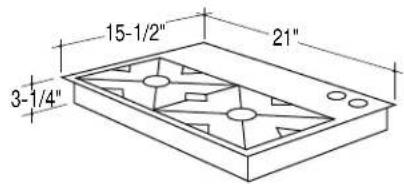


Design Information
| Component Cooktop System | ||||
| Installation Accessories Provided | Joiner strips and end caps are included to provide a finished look to any modular cooktop arrangement. |  | ||
| End Cap | Downdraft Joiner | Joiner Downdraft End Cap | ||
| Advance Planning | ·Consider base cabinet storage arrangements to accommodate the downdraft blower/motor assembly.-The downdraft plenum assembly will occupy the cabinet below the cooktop. Drawers cannot be installed below the downdraft vent or downdraft grill components. The blower may be installed in the cabinet or located downstream from the plenum in the duct run.-Shorter length drawers may be installed below gas components, allowing for gas inlet clearance.·Do not cut holes for ductwork locations until components are on-site, with countertop in place, and all pre-planned locations are confirmed. | ·Always pre-plan electrical and gas connections to be accessible at the time of installation.·Consider the distance to power supply, cable length and bending restrictions before cutting holes.·Gas components are not convertible to liquid propane operation.·In the absence of local codes, the gas cooktop must comply with the National Fuel Gas Code, ANSI Z223.1, latest edition.UL, A.G.A. approved. | ||
| Installation Options | ·Multiple gas and electric components can be combined to form one custom cooking arrangement.-Multiple electric components can operate from a single junction box, if local codes permit.-Multiple gas components can operate from a manifold, as permitted by local codes.·Updraft components can be vented according to normal exhausting methods.·The downdraft vent and grill blower assembly may be vented downwards to the left or right sides or through the floor. See page 11. | -The motor blower assembly can be mounted in the cabinet or under the floor. The blower will fit between floor joists on 16" centers.-The plenum on the downdraft grill and vent is shipped with the discharge on the left side. It can be changed to discharge from the right side.·JXBC55 optional outdoor cover accessory may be ordered for installation of blower and motor assembly on an outside wall. | ||
| Installation Rules | ·Never vent a cooktop into an interior space - always to the outdoors.·The updraft grill requires an overhead vent with at least 300 CFM.·DO NOT install an updraft grill component next to a downdraft vent. | ·DO NOT install a downdraft vent behind a cooktop.·DO NOT install a gas or grill cooktop where the knobs are between the heated area and the downdraft vent. | ||
Installation Location
- Whenever possible, avoid placing cabinetry directly above the cooking surface.
- If cabinetry is used above the cooking surface:
-Use cabinets no more than 13" deep.
-Maintain 30" minimum clearance between cooktop(s) and unprotected cabinets directly above the cooktop.
-If clearance is less than 30", protect cabinet bottoms with flame-retardant millboard at least 1/4" thick or gypsum board at least 3/16" thick covered with 28 gauge sheet steel or .02" thick copper.
-Clearance between cooktop and protected cabinetry must not be less than 24".
- Working areas next to the cooktops should have 18" minimum clearance between the countertop and the cabinet bottom.
EXCEPTION: Installation of a listed microwave oven or cooking appliance over the cooktop(s) shall conform to the installation instructions packed with that appliance.
- Installation must conform with local codes.

* Gas in side to side orientation requires 2" min. to rear wall.
[]
** Gas requires 2" min. to side wall.
Clearances:
- When installed electric components require the following clearances:
- 2" min. from front of cooktop to front edge of countertop,
-1" min. from back of cooktop to rear wall,
-1" min. from side of cooktop to side wall.
Gas components require:
-2" min. from back of cooktop to rear wall,
-2" min. from side of cooktop to side wall.
Cabinetry
Component Cooktop System
Tools & Materials Required (Not supplied)
- Carpenter's square
- Measuring tape
- Saw
-
2 Phillips head screwdriver bit socket • Phillips screwdriver
- 1/4" nutdriver
- 5/16" nutdriver
- 7/16" and 5/16" socket and ratchet wrench
- Pencil
- Scissors
- Level
- Hole saw
-6" 90° elbow - Duct work to suit the installation.
For Gas Components:
- Pipe wrench
• Gas line to reach installation location
• Gas resistant pipe joint sealant. - Manual gas line shut-off valve
- 3/4" NPT x 3/4" I.D. or 1/2" NPT x 1/2" I.D. flare union adapter
- 1/2" NPT x 3/4" I.D. or 1/2" I.D. flare union adapter
- 5 foot AGA certified flexible metal appliance connector, 3/4" x 1/2" I.D. to match gas supply line.
-If required by local codes, use solid pipe with fittings.
NOTE: Use new flexible line. DO NOT use old, previously used flexible line.
Cutout Information
4" Minimum Between Cutouts

Front to Back Orientation
- Minimum clearance is 4" between cooktops in separate cutouts. This clearance does not apply when multiple component cooktops are installed in one cutout.
4" Minimum Between Cutouts

Side to Side Orientation
NOTE: Do not install a downdraft vent in a side to side orientation behind a gas or halogen component. This would require the user to reach over a heated surface to access the control.
Find Dimension A in chart below and on the following page.

Cut the opening as shown above. Measure carefully when cutting countertop, making sure sides are parallel and front and rear cuts are perpendicular to sides.
- The front and rear of the opening must clear support rails of the cabinet.
- The cutout depth (front to back) is 19-1/2" for all components.

A
Halogen 14-1/2"
Gas 14-1/2"
Updraft grill 15-3/8"
Downdraft Grill 20-3/4"
Downdraft Vent 5-1/8"
Cabinetry
Component Cooktop System
Cutout Information (Continued)
If your configuration is not shown in the previous charts, use the following chart to calculate your cutout
size. For each of the following components, add the dimensions given.
Component/ Connector Model/ Name Width Quantity Sub Total Width

ZEW145V Halogen and Ribbon Component 14-1/2"

ZGW124EN3 ZGW125EN3 Gas Component 14-1/2"

ZEW166Y Downdraft Grill Component 20-3/4"

ZEW155N Updraft Grill Component 15-3/8"

Downdraft Vent ZEW176Y Component 5-1/8"
Connection between two cooktops (including updraft grill and non-vent Joiner Strip side of downdraft grill) 3/4"

Connection between cooktop and Downdraft downdraft vent or vent Joiner Strip side of downdraft grill 1/4"

Provide finished look to Cooktop and component cooktop Downdraft arrangement. Do not Vent End count as part of Caps cutout width. 0" 0"
Total Cutout Width-
Cutout Information: Multiple Components Example

Cutout information: multiple component units
If multiple components will be attached together, determine dimension A from the following:
Unit 1 Unit 2 Unit 3 Unit 4 Unit 5 A

Halogen Halogen 29-3/4"

RH Gas RH


LH Gas LH


Halogen Updraft 30-5/8"

Grill

RH Gas

LH Gas

Updraft Updraft 31-1/2"

-1/2"

Downdraft

Halogen 19-7/8"

RH Gas

Downdraft

Halogen 35-1/2"

RH Gas

Halogen Downdraft
Haloger
Vent*


LH Gas

RH Gas

Downdraft

Halogen

Halogen

RH Gas

RH Gas

LH Gas

Halogen

Downdraft

Halogen

Downdraft
Vent*

Halogen 54-3/4"

Downdraft
Vent*

Halogen

LH Gas

Downdraft
Vent*

Halogen 55-1/4"

RH Gas

RH Gas

Halogen

Downdraft

Downdraft

Halogen
55-5/8"

LH Gas

[Non-Text]

[Non-Text]

RH Gas
* See "Venting rules" concerning placement of knobs in relation to downdraft vent.
If your configuration is not shown, refer to following page.
Ductwork
Component Cooktop System
Venting Options

natural_image
Pure technical line drawing of a mechanical assembly without any text, numbers, or symbols
natural_image
Technical line drawing of a mechanical assembly or structural component (no text or symbols)Through Floor Between Joists Through Floor & Under Joists
Multiple cooktops and downdraft vent units may be used in a single arrangement.
- Plan the route for venting exhaust to the outdoors.
- Ductwork must be vented to outdoors - never to a crawl space, attic or other enclosed space.
- Duct should be located between floor joists or wall studs whenever possible.
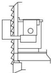
- Blower and motor assembly can be installed on an outside wall. JXBC55 optional outdoor cover accessory is required and must be ordered with each downdraft venting unit.
- Every downdraft vent and downdraft grill must have it's own, separate duct run.

natural_image
Technical line drawing of a mechanical assembly with no visible text or symbolsInside Wall To Roof
natural_image
Technical line drawing of a mechanical assembly with no visible text or symbolsDirect To Outdoors ☐ With JXBC55 Mounted☐ On Outside Wall
Ductwork Advance Planning
-
Use the shortest and straightest duct run possible.
-Duct run for Downdraft Grill Component, ZEW166Y, should not exceed equivalent length of 100 feet.
-Duct run for Downdraft Vent, ZEW176Y, should not exceed equivalent length of 150 feet.
-Refer to "Duct Fittings" chart to calculate equivalent length for various duct configurations. -
The downdraft blower system is designed for use with 3-1/4" x 10" ductwork. It can be transitioned to 6" round.
- Ductwork MUST be vented to the outside – never into a crawl space, attic or other enclosed space.
Optional Ductwork Arrangement
6" PVC duct should be used when installing under a concrete slab.
- Use recommended wall caps with damper. Do not use laundry type wall caps.
- Ductwork must be vented to the outside.
• Each cooktop blower system requires a separate duct system.
NOTE: Local building code must be followed for installation and in specifying approved type and schedule of PVC duct used.

natural_image
Pure technical line drawing of a pipe fitting or valve assembly without any text, labels, or symbolsDetermine Ductwork Location

Discharge left side (not to scale)

Discharge right side (not to scale)
To accurately locate the ductwork holes in the cabinet floor:
- Place all components into the cutout, arranged in the exact position they will be installed.
- Place a 90^ elbow over the discharge outlet and into the blower motor assembly.
- Position the transition duct on the end of the blower motor assembly.
- Mark the location and remove the components and blower motor assembly.
- Cut holes and install ductwork connections.
- The discharge on the plenum is located on the left side. To change to the right side, remove 2 screws on each side of the plenum below the cooktop flange. Rotate the plenum and re-install screws.

Discharge through the floor (not to scale).
Install Blower Assembly
Install blower
- The blower can be mounted in the cabinet or under the floor. The blower will fit between floor joists on 16" centers.
- For installation where the blower is mounted inside the cabinet, attach the mounting supports to the bottom corners of the blower housing. (The motor is on the bottom side, the 6" round opening is the top side).
- If the blower is installed under the floor, attach the mounting supports to the top corners (the side with the 6" round opening).
NOTE: Do not drill additional holes in the blower.
Adjust mounting supports
- Adjust the height of the mounting supports by sliding the two halves up or down. With supports at desired length, install bolts and nuts into the supports.
- Secure the blower to the cabinet floor or between floor joist with screws provided.
Finalize Ductwork
- Install ductwork, making connections in the direction of airflow as shown.
- Secure all joints with sheetmetal screws.
- Wrap joints with duct tape for airtight seal.
- Install a wall cap with damper or roof cap at exterior opening.

Duct fittings
Use copies of this form to compute maximum permissible lengths for duct runs to outdoors.
ZEW166Y Downdraft Grill Component maximum equivalent length is 100 feet.
ZEW176Y Downdraft Vent Component maximum equivalent length is 150 feet
Note: Do not exceed maximum permissible equivalent lengths!
Flexible ducting: If flexible metal ducting is used, all the equivalent length values in the table should be doubled. The flexible metal duct should be straight and smooth and extended as much as possible.
Do NOT use flexible plastic ducting.
CAUTION:
Any home ventilation system, such as a cooktop with a downdraft exhaust mechanism, may interrupt the proper flow of combustion air and exhaust required by fireplaces, gas furnaces, gas water heaters and other naturally vented systems. To minimize the chance of interruption of such naturally vented systems, follow the heating equipment manufacturer's guidelines and safety standards such as those published by NFPA and ASHRAE.
| Duct Piece Dimensions Length* Used Length | Total Equivalent Quantity Equivalent | |
 | 6" round, (per foot straight length) | 1 ft. |
 | 3-1/4" x 10" (per foot straight length) | 1 ft. |
 | 6"90° elbow 15 ft. | |
 | 6"45° elbow 9 ft. | |
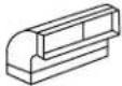 | 3-1/4" x 10"90° elbow 15 ft. | |
 | 3-1/4" x 10"45° elbow 9 ft. | |
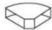 | 3-1/4" x 10"90° flat elbow 20 ft. | |
 | 6" roundto 3-1/4" x 10"transition 1 ft. | |
 | 3-1/4" x 10"to 6" roundtransition 5 ft. | |
 | 6" round to3-1/4" x 10"transition90° elbow 5 ft. | |
 | 3-1/4" x 10" to 6"round transition90° elbow 15 ft. | |
 | 6" roundwall capwith damper 30 ft. | |
 | 3-1/4" x 10"wall capwith damper 30 ft. | |
 | 6" roundroof cap 26 ft. | |
 | 6" roundroof vent | 24 ft. |
*Actual length of straight duct plus duct fitting equivalent. Equivalent length of duct pieces are based on actual tests conducted by GE Evaluation Engineering and reflect requirements for good venting performance with any downdraft cooktop.
Total Duct Run____
Component Cooktop System
Gas Supply Location
- Gas components are designed to operate on natural gas at 4" water column pressure.
These cooktops are supplied with 1/2" NPT male gas connections. The connection for models with right hand controls is on the bottom right corner, and left hand control models on the left corner. - Gas components cannot be converted to LP gas operation.
- Make gas connection through the rear wall, or on the cabinet floor at the rear.
- For rigid connection, locate pipe stub: -4-7/ 16" from center line of appliance, -on the back wall, at least 12" below countertop, -on the floor, 2-1/ 2" forward of the back of the countertop cutout.
For flexible connection, locate pipe stub on floor or back wall in a convenient location. - Install a manual shut-off valve in the gas line in an easily accessible location.
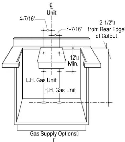
* Important: 12" min. is specified to allow space for shut-off valve if supply is opted to enter from rear.
Both left and right-controlled gas components are illustrated together in order to compare their supply rough-in locations.
Electrical Supply
Halogen and ribbon components operate on 240/208 volt, 60 Hz. Updraft grill and downdraft grill components operate on 240 volt, 60 Hz. Gas and downdraft vent components operate on 120 volt, 60 Hz. from a separate junction box. A dedicated circuit, protected by a time delay fuse or circuit breaker is required for cooktops. The downdraft vent requires an appliance circuit with a time delay fuse of circuit breaker.
- If local codes permit, more than one cooktop can be used on the same branch circuit. See local codes or the National Electrical Code for circuit demand loads.
WARNING: DO NOT USE AN EXTENSION CORD WITH THESE APPLIANCES.


Installation
Component Cooktop System
Step 1 Apply Gasket Strip
Apply foam tape (supplied) on top surface of countertop along all edges of the cutout.

natural_image
Line drawing of two hands using a ruler to cut a rectangular object (no text or symbols)Step 2 Remove Knobs, Gates
3 Joining Multiple Cooktops
- Turn all control knobs to OFF position.
- Carefully remove knobs by lifting straight up.
- Remove all grates, burner caps and vent covers from components.
- Remove tape covering screw holes on the downdraft grill.


natural_image
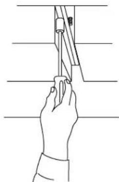
Line drawing of a hand holding a tool, no text or symbols present- Lay cooktops upside down on a clean flat work surface.
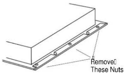
- Remove endcaps on sides to be joined by removing three nuts with a 5/16" nutdriver. Discard nuts.
-
Attach joiner strip to first cooktop by tightening flanged nuts (supplied) over the flanges.
-
Place the two cooktops into the countertop cutout.
- Slide the cooktops together so that the slots in the joiner strip are engaged by the studs. There should be no gaps between cooktops and joiners. Press together firmly to assure a tight fit.
- Place flanged nuts in end of 5/16" nutdriver. Start nuts on studs and tighten from below.
Attach chassis support brace to equal-height cooktops
- When attaching gas to gas, gas to halogen, halogen to halogen or grill to grill, place support brace as shown.
- Remove one screw from the center of each cooktop chassis.
- Position brace and tighten screws.
- Repeat these steps for three cooktops.

natural_image
Technical line drawing of a mechanical assembly with two bracket components and a magnified inset (no text or symbols)Joining Multiple Cooktops (Continued)
Attach chassis support brace to different height cooktops
- When attaching grill to halogen or gas, place the support brace as shown.
- Remove one screw from the center of each cooktop chassis.
- Position brace and tighten screws.
- Repeat these steps for three cooktops.


Joining Cooktop to Downdraft Vent
- Remove all grates, knobs, burner caps and drip pans.
- Lay cooktop upside down.
- Remove endcap on side of cooktop to be joined by removing three nuts with a 5/16" nutdriver.

natural_image
Line drawing of a hand using a tool to adjust or install components on a mechanical assembly (no text or symbols)Important: Pre-tap holes in downdraft joiner and endcaps by driving supplied screws through holes and then backing out before installation. This will make the joining process easier.
- Replace endcap with downdraft joiner strip using the same three nuts.
-If the vent is to be installed at the end of the countertop opening, attach downdraft endcap to that side.
- Place the downdraft vent and cooktop into the cutout.
- Remove two screws from the front of cooktop chassis. Drive the two screws into holes below the downdraft vent flange as shown. Use a phillips screwdriver bit socket.
- If downdraft vent is installed at the end of the cutout, secure the downdraft endcap to the countertop by driving two phillips head screws as shown.
- To finalize installation, proceed to "Securing cooktop(s) to countertop.
- If additional cooktop(s) are to be installed, proceed to "Joining additional cooktop to downdraft vent or downdraft grill."

Joining
Multiple
Cooktops
(Continued)

Joining additional cooktop to downdraft vent or to downdraft grill
- Remove endcap on the side of the next cooktop to be joined.
- Pre-tap holes in downdraft joiner and endcaps by driving supplied screws through holes and then backing out before installation. This will make the joining process easier.
- Attach downdraft joiner strip to cooktop.
- Place cooktop next to downdraft vent in the cutout.
- Drive two phillips head screws into pre-tapped holes. Use a phillips screwdriver bit socket.
- To install additional vent or cooktop(s), refer to "Joining Multiple Cooktops."

Secure
Cooktop(s)
to Countertop
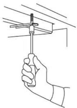
- Loosen screws on hold-down brackets at each end of cooktop. Extend the bracket to reach the underside of the countertop. Tighten screws.
- Drive a long screw (2 lengths are provided) through the bracket until screw is tight against the bottom of the countertop.
natural_image
Line drawing of a hand using a screwdriver to lift a pipe (no text or symbols)
Connect Gas
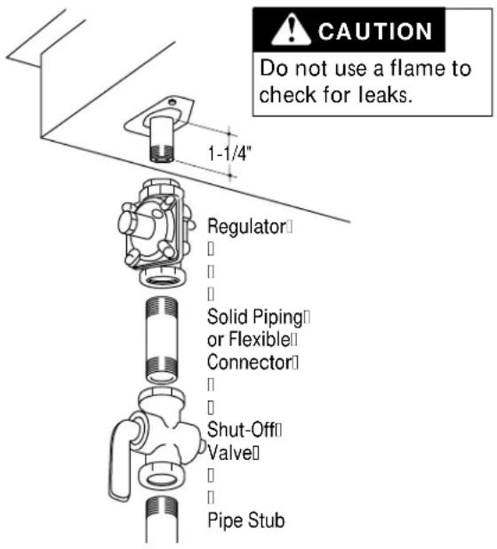
• Install the supplied pressure regulator in gas supply line as close to the cooktop inlet as possible. Allowances for ventilation ducting may be required.
—The regulator should be installed with the arrow pointing in the direction of gas flow.
- Install a manual gas shut-off valve where it will be easily reached. Be sure the user knows where and how to shut off the gas supply.
- Appropriate flare union adapters are required at each end of a flexible connector.
- Turn on the gas and check for leaks. Use a liquid leak detector at all connections in the system. A pressure test fitting is located on the pressure regulator.
NOTE: If local codes permit, use 5 foot AGA-certified flexible metal gas supply line. 3/4" or 1/2" I.D. to match gas supply line.
Do not use old, previously used flexible line.
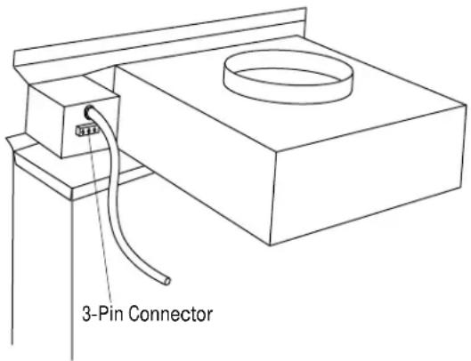
Connect electrical to downdraft vent
- Connect the 3-pin plastic plug from the blower/ motor assembly to the 3-pin plastic socket on the underside of the vent controls.
- Fasten the wire box on the conduit over the plug and onto the bottom of the control box with screws provided.
The blower conduit is long enough to reach the vent connection when installed in the cabinet below. The conduit will also reach some blower installations below the cabinet floor.
- If the blower conduit is not long enough to reach the vent connection, the leads can be extended.
To add conduit length:
- Install an appropriate junction box near the blower.
- Remove the wire box from the end of the blower conduit.
- Cut the leads approximately 3" from the plug.
- Cut a length of electrical cable to reach the junction box. Use 14 gauge min. electrical cable (or conform to local codes).
- Attach the wire box and plug to one end of the cable. Connect opposite end of cable to blower leads in the junction box.

flowchart
graph TD
    A["Vent"] --> B["Electrical Box (with vent)"]
    B --> C["Power Cable (not included with vent)"]
    B --> D["Junction Box (not included with vent)"]
    D --> E["To Blower"]
    style A fill:#f9f,stroke:#333
    style B fill:#ccf,stroke:#333
    style C fill:#cfc,stroke:#333
    style D fill:#fcc,stroke:#333
    style E fill:#ffc,stroke:#333

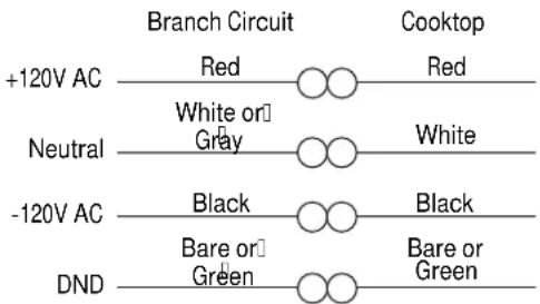
3-Conductor branch circuit:
- Connect red lead to branch circuit red lead.
- Connect black lead to branch circuit black lead.
- Connect bare or green conductor and white lead * of the cooktop to branch circuit neutral lead, which is white or gray.
4-Conductor branch circuit:
- Connect red lead to branch circuit red lead.
- Connect black lead to branch circuit black lead.
- Break connection between cooktop white lead to bare or green conductor.
- Connect cooktop white lead* to branch circuit neutral lead, which is white or gray.
- Ground unit by connecting bare conductor of cooktop to branch circuit bare or green lead (ground lead).
The frames of these appliances are grounded to neutral.
* Updraft grill has no white neutral wire. Connect only black, red and bare wires as shown.
3-Conductor Branch Circuit

4-Conductor Branch Circuit
Electrical
Power
Requirements
Model Voltage Frequency AMPS KW
ZGW124EN3 120 60 Hz 1.0 —
ZGW125EN3 120 60 Hz 1.0 —
ZEW145V 208 60 Hz 11.0 2.3
ZEW145V 240 60 Hz 12.7 3.0
ZEW155N 240 60 Hz 7.3 1.8
ZEW166Y 240 60 Hz 13.5 3.3
ZEW176Y 120 60 Hz 1.8 —
Finalize Installation
Install downdraft vent filter
- Place filter into the opening and on top of the supports.
- Place grille over the filter.

Electric Components:
Push in and turn each knob to high position.
Make sure each element heats up.
Gas Components:
(Electrical connections should be complete).
- Plug power cord into outlet.
- Assemble burner(s) as shown.
- Check for proper ignition:
-Push in control knob and turn 90° to HIGH position.
- First test may require some time, while air is flushed out of the gas line.
-Turn knob to OFF.
-Repeat the procedure for each burner.
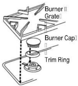

CAUTION
Do not operate
the burners until all burner parts are in place.
Note: While performing installations described in this book, safety glasses or goggles should be worn.
To obtain specific information concerning any Monogram product or service, call GE Answer Center® consumer information service at 800.626.2000—any time, day or night.
For Monogram local service in your area, call 1-800-444-1845.
NOTE: Product improvement is a continuing endeavor at General Electric. Therefore, materials, appearance and specifications are subject to change without notice.
Pub. No. 49-8834
Dwg. No. 164D3333P076
1997 GE Appliances
Printed in USA
(N.D. 751) 7/97



- Contents
- Product Dimensions
- ZEW166Y
- ZGW124EN3
- ZGW125EN3
- Installation Location
- Clearances:
- Cabinetry
- Phillips head screwdriver bit socket
- For Gas Components:
- Cutout Information (Continued)
- Ductwork
- Venting Options
- Ductwork Advance Planning
- Optional Ductwork Arrangement
- Determine Ductwork Location
- Install Blower Assembly
- Install blower
- Adjust mounting supports
- Finalize Ductwork
- Duct fittings
- CAUTION:
- Gas Supply Location
- Electrical Supply
- Installation
- Attach chassis support brace to equal-height cooktops
- Attach chassis support brace to different height cooktops
- Joining Cooktop to Downdraft Vent
- Joining additional cooktop to downdraft vent or to downdraft grill
- Connect electrical to downdraft vent
- To add conduit length:
- 3-Conductor branch circuit:
- 4-Conductor branch circuit:
- Finalize Installation
- Install downdraft vent filter
- Electric Components:
- Gas Components:
- CAUTION
Brand : GE
Model : ZGW124ENSS
Category : Hob