
EPN12C58HWI - Heat pump ELECTROLUX - Free user manual and instructions
Find the device manual for free EPN12C58HWI ELECTROLUX in PDF.


| Product Type | Heat Pump |
| Brand | Electrolux |
| Model | EPN12C58HWI |
| Dimensions (H x W x D) | 800 x 600 x 300 mm |
| Weight | 45 kg |
| Power Supply | 230V / 50 Hz |
| Power Consumption (Cooling) | 1.2 kW |
| Power Consumption (Heating) | 1.0 kW |
| Cooling Capacity | 3.5 kW |
| Heating Capacity | 4.0 kW |
| Energy Efficiency (EER) | 3.2 (Cooling) |
| Energy Efficiency (COP) | 3.5 (Heating) |
| Refrigerant Type | R32 |
| Noise Level (Indoor) | 45 dB(A) |
| Noise Level (Outdoor) | 55 dB(A) |
| Functions | Cooling, Heating, Dehumidifier, Fan |
| Remote Control | Included |
| Air Filter | Washable |
| Installation Type | Split System |
| Spare Parts Availability | Yes, via Electrolux service |
Frequently Asked Questions - EPN12C58HWI ELECTROLUX
User questions about EPN12C58HWI ELECTROLUX
0 question about this device. Answer the ones you know or ask your own.
Ask a new question about this device
Download the instructions for your Heat pump in PDF format for free! Find your manual EPN12C58HWI - ELECTROLUX and take your electronic device back in hand. On this page are published all the documents necessary for the use of your device. EPN12C58HWI by ELECTROLUX.
USER MANUAL EPN12C58HWI ELECTROLUX
WE'RE THINKING OF YOU
Thank you for purchasing an Electrolux appliance. You've chosen a product that brings with it decades of professional experience and innovation. Ingenious and stylish, it has been designed with you in mind. So whenever you use it, you can be safe in the knowledge that you'll get great results every time.
Welcome to Electrolux.
Visit our website to:

Get usage advice, brochures, trouble shooter, service information: www.electrolux.com

Register your product for better service: www.electrolux.com/productregistration

Buy Accessories, Consumables and Original spare parts for your appliance: www.electrolux.com/shop
CUSTOMER CARE AND SERVICE
We recommend the use of original spare parts.
When contacting Service, ensure that you have the following data available.
The information can be found on the rating plate. Model, PNC, Serial Number
Warning / Caution-Safety information.
General information and tips.
Environmental information.
Subject to change without notice.
1. ⚠️ SAFETY INSTRUCTIONS
Before the installation and use of the appliance, carefully read the supplied instructions. The manufacturer is not responsible if an incorrect installation and use causes injuries and damages. Always keep the instructions with the appliance for future reference.
1.1 Children and vulnerable people safety

WARNING!
Risk of suffocation, injury or permanent disability.
- This appliance can be used by children aged from 8 years and above and persons with reduced physical, sensory or mental capabilities or lack of experience and knowledge if they have been given supervision or instruction concerning use of the appliance in a safe way and understand the hazards involved.
• Children shall not play with the appliance. - Cleaning and user maintenance shall not be made by children without supervision.
1.2 Installation and Use

WARNING!
Risk of suffocation, injury or permanent disability.
- Contact an authorised installer for installation of this unit.
- Contact an authorised service technician for repair or maintenance of this unit.
- The socket outlet required to supply power must be connected and commissioned by a licenced contractor.
- If the supply cord is damaged, it must be replaced by the manufacturer, its service agent or similarly qualified persons in order to avoid a hazard.
• Installation work must be performed in accordance with the national wiring standards and the electricity
suppliers service rules by authorised personnel only.
- If the unit is to be moved to another location or disposed of, only a suitably qualified person is permitted to undertake such work.
- If you notice an unusual situation, such as a burning smell, please switch off the power to the air conditioner and contact the brand service agent. If this abnormal status continues the air conditioner may be damaged or even cause electric shock or fire.
- Do not operate the air conditioner with wet hands. This may cause electric shock.
- Do not damage or cut off the power cord or other wires. If this occurs, please have it repaired or replaced by an accredited technician.
- Do not connect this air conditioner to a multi outlet power board.
- Please switch off the power supply to the air conditioner if it is not to be used for an extended period. Otherwise, it will accumulate dust and may cause a fire.
- Before cleaning the air conditioner, please disconnect the power supply in order to eliminate the possibility of electric shock.
- The power supply should be matched with the air conditioner. Air conditioners provided with a supply cord should be connected directly to a power outlet with a suitable safety switch. Air conditioners that are hard wired must be connected to a suitable safety circuit breaker.
- Please ensure that the power supply to the air conditioner is stable and meets the requirements set out in the installation manual.
• Always ensure the product is installed with appropriate earthing.
- For safety, be sure to turn off the circuit breaker before performing any maintenance or cleaning or when the product is not used for an extended period of time. Accumulated dust may cause fire or electric shock.
- Select the most appropriate temperature. It can save electricity.
- Do not keep windows and doors open for a long time during operation. It will result in insufficient performance.
- Do not block the air inlet or outlet. It will result in insufficient performance and cause malfunctions.
- Keep combustible materials away from the units at least 1 meter. It may cause fire.
-
Do not step on the top of the outdoor unit or place heavy things on it. It may cause damage or injury.
-
Do not attempt to repair the air conditioner by yourself. Incorrect repairs may cause electric shock or fire. Please contact your local authorised service centre.
- Do not insert your hands or objects into the air inlet or outlet. It may cause injury.
- Do not expose animals or plants directly to the airflow.
- Do not use the unit for any other purpose, such as preserving food or drying clothes.
- Do not splash water on the air conditioner. It may cause electric shock or malfunction.
- This air conditioner uses R32 refrigerant.

R32 refrigerant warning
This product uses R32 difluoromethane refrigerant, which is a mildly flammable gas class 2.2 according to ISO 5149 and must be handled by a refrigeration mechanic with appropriate refrigerant handling licence.
2. PRODUCT DESCRIPTION
All the pictures in this manual are for explanation purposes only. The actual shape of the indoor unit you purchased may be slight different on front panel and display window. The actual shape shall prevail.
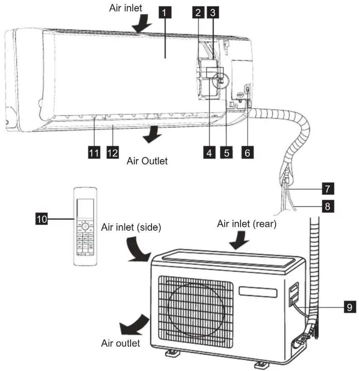
1 Front panel
2 Pre-dust filter
3 Air filter
4 Digital display
5 Cold plasma generator (inside)
6 Manual control button
7 Refrigerant pipe
8 Drain hose
9 Connecting cable
10 Remote controller
11 Vertical air flow louver
12 Horizontal air flow grille
3. INDOOR UNIT DISPLAY
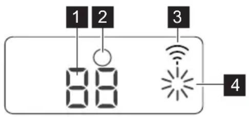
1 TEMPERATURE indication lamp
- Displays the setting/room temperature when the air conditioner is operational.
- Displays the malfunction code when fault occurs.
- Displays the function code when some function is activated.
2 Signal receiver
Beeping sound is generated when a signal from remote controller is received.
3 Wi-Fi mode lamp
Lights up when the Wi-Fi function is setting.
4 Operation mode lamp
Lights up when the unit is working in Cool, Heat or Dry mode.
4. REMOTE CONTROLLER
4.1 How to use the Remote controller
- Keep the remote controller where its signal can reach the receiver of the indoor unit.
- When operate the air conditioner, make sure the remote controller is pointing to the signal receiver of the indoor unit.
- When the remote controller sends out a signal, the symbol “⚠️ will blink for about 1 second in the display of the remote controller.
- The indoor unit will acknowledge the signal with beep sound when it receives an effective signal from the remote controller.
- Please press the button of the remote controller and resend the signal if you did not hear beep sound from the indoor unit.

- The air conditioner will not operate if curtains, doors or other materials block the signals from the remote controller to the indoor unit.
- Prevent any liquid from falling into the remote controller. Do not expose the remote controller to direct sunlight or heat.
- If the infrared signal receiver on the indoor unit is exposed to direct sunlight, the air conditioner may not function properly. Use curtains to prevent the receiver being exposed to sunlight.
- If other electrical appliances react to the remote controller, either move these appliances or consult your local dealer.
4.2 Location of the Remote Controller
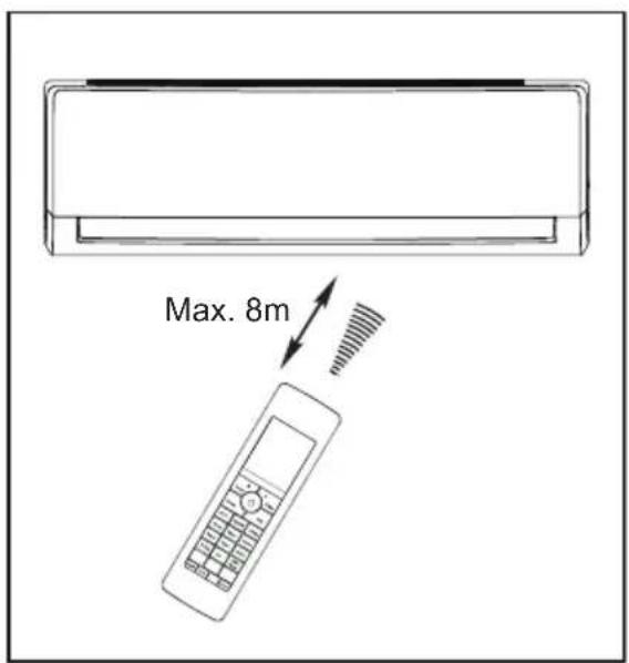
- Keep the remote controller where its signal can reach the receiver of the indoor unit (a maximum distance of 8 m is allowed).
- When the remote controller sends out a signal, the symbol “⚠️” will blink for about 1 second on the display. The indoor unit will acknowledge the signal with beep sound when it receives an effective signal.
4.3 Battery installation/replacement
natural_image
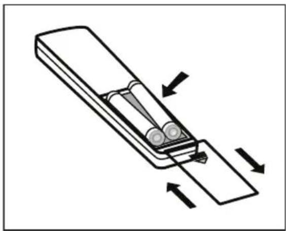
Diagram of a battery moving in a row with arrows indicating direction (no text or symbols)- Slide the back cover from the remote controller, exposing the battery compartment and insert two new alkaline dry batteries (2x AAA 1.5 Volt). Make sure that the polarity of (+) or (-) is installed correctly.
- Slide the battery compartment cover back on.

- When changing batteries, do not use old or varied ones, otherwise, it may cause problems with the remote controller.
- If the remote controller is not used for a long time, remove the batteries as old batteries may leak or corrode and damage the remote controller.
• The battery life during normal use is about six months. - If the remote controller does not operate normally, please remove and refit the batteries. If abnormal operation continues, replace with new batteries.
5. REMOTE CONTROLLER DESCRIPTION
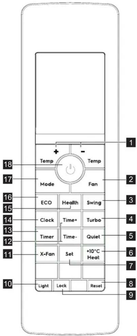
1 Temp +/- Button
2 Fan Button
3 Swing Button
4 Turbo Button
5 Quiet Button
6 +10°C Heat Button
7 Set Button
8 Reset Button
9 Lock Button
10 Light Button
11 X-Fan Button
12 Time +/- Button
13 Timer Button
14 Clock Button
15 Health Button
16 Eco Button
17 Mode Button
18 On/Off Button
ON/OFF BUTTON
Press the button to switch on or off the unit.
MODE BUTTON
Press the button to set the operation mode: AUTO, COOL, DRY, FAN and HEAT. Default setting: AUTO.

flowchart
graph LR
    A["AUTO"] --> B["COOL"]
    B --> C["DRY"]
    C --> D["F"]
    D --> E["AN"]
    E --> F["HEAT"]
• In AUTO mode, user can still set desired temperature.
ECO BUTTON
In COOL, HEAT or DRY mode, press this button to enable or disable Eco operation. If the ECO function is enabled, the ECO symbol "will be shown. Default setting: OFF.
This is ideal for the users to use while sleeping.
HEALTH BUTTON
Press the button to enable or disable the the health function. If the function is enabled, the symbol "L" will be shown.
CLOCK BUTTON
Press the button to set the clock. If the clock symbol “A” or “” blinks, press the Time +/- button to set the time. Keep the button pressed for five seconds to accelerate the process. Press the Set button to set the clock. The clock symbol stops blinking.
TIMER BUTTON
Press the button to set the timer function for switching on/off the unit. If the Timer symbol “OK” ” b OFF, press the
Time +/- button to set the timer. Keep the button pressed for five seconds to accelerate the process. Then press the Set button to set the timer. Press the Timer button again till the timer symbol disappeared to cancel the timer function.
TIME +/- BUTTON
Press the button to increase/decrease the time setting. Keep the button pressed for five seconds to accelerate the process.
X-FAN BUTTON
In COOL or DRY mode, press the button to enable or disable the X-FAN function. Default setting: OFF.
LIGHT BUTTON
Press the button once to show the ambient temperature.
Press the button twice in a row in 5 seconds to switch the display of the indoor unit off.
Default setting: ON.

- Continuous pressing Light button 7 times in 10s, the unit will enter the Wi-Fi binding status.
TEMP +/- BUTTON
Press the button to increase/decrease the temperature.
Temperature range: 16-30°C.
FAN BUTTON
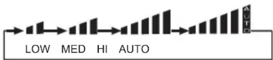
Press the button to set the fan speed: LOW, MEDIUM, HIGH and AUTO. In the AUTO and DRY mode, fan speed can also be set.
flowchart
graph LR
    A["Low"] --> B["MED"]
    B --> C["HI"]
    C --> D["AUTO"]
    D --> E["Output"]
SWING BUTTON
Press the button to activate swing function. Press again to cancel it.

- Short press the button will activate up/down swing. And long 1 second press will activate left/right swing.
- For some models, you can only adjust the louver left/right manually.
TURBO BUTTON
Press the button to enable or disable the turbo function. When enable the function, the symbol “” will be shown
When in turbo function, the fan will run in highest speed.
QUIET BUTTON
Press the button to enable or disable the quiet function. When enable the function, the symbol “” will be shown.
When in Quiet function, the fan will run in slowest speed.
+10°C HEAT BUTTON
In Heat mode, press the button to enable +10°C heat function. When enable the function, the temperature will set with 10°C. Switch mode and adjust the temp setting will cancel the setting.
SET BUTTON
In Timer and Clock setting, press the button to confirm the setting.
RESET BUTTON
Press the button to reset the remote controller, the set will back to default setting.
LOCK BUTTON
Press this button to lock and unlock the remote controller. When enable the function, the symbol "⚡" will be shown.
Default setting: OFF.
6. REMOTE CONTROLLER DISPLAY INDICATOR
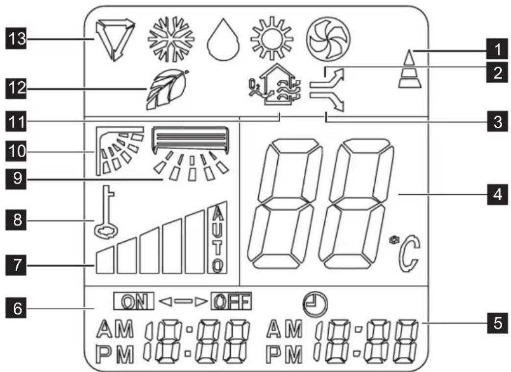
1 Transmission Indicator
2 Turbo display
3 Quiet display
4 Temp display
5 Clock display
6 Timer display
7 Fan display
8 Lock display
9 Swing left/right display (Optional)
10 Swing up/down display
11 Health display
12 Eco Indicator
13 Mode display
MODE DISPLAY
Displays the current selected mode.
Including AUTO, COOL, DRY, FAN and HEAT.
ECO DISPLAY
Displays when Eco function is enabled.
HEALTH DISPLAY
Displays when Health function is enabled.
SWING UP/DOWN DISPLAY
Displays when Swing function is enabled.
SWING LEFT/RIGHT DISPLAY
Displays when Swing function is enabled.
LOCK DISPLAY
Displays when Lock function is enabled.
FAN DISPLAY
Displays the selected fan speed: AUTO, LOW, MED and HIGH. When FAN Mode
is selected, there will be no AUTO speed to be selected.
TIMER DISPLAY
Displays when the Timer function is enabled.
TRANSMISSION INDICATOR
Displays when the remote controller transmits signals to the indoor unit.
TURBO DISPLAY
Displays when Turbo function is enabled.
QUIET DISPLAY
Displays when the Quiet function is enabled.
TEMP DISPLAY
Displays the set temperature.
CLOCK DISPLAY
Displays the set Clock time.
7. FIRST USE
- Ensure the unit is plugged in and power is available.
- Be sure the batteries are inserted correctly in the remote controller (the lights on the remote control will be on).
- Point the remote controller to the indoor unit and press ON/OFF button to turn the unit on.

- In case of energy cut off or product shut down when removing the power cord, or even when changing the remote controller batteries the
microprocessor will return back to the default setting.
- The default operating mode is AUTO. Once you select the operating mode with remote controller, the operating conditions will be saved in the indoor unit's microcomputer memory. The next time the air conditioner will start operating under the same conditions when you simply push the ON/OFF button of the remote controller.
8. HOW TO USE THE REMOTE CONTROLLER

Ensure the unit is plugged in and power is available. The OPERATION indicator on the display panel of the indoor unit illuminates.
Basic Operation
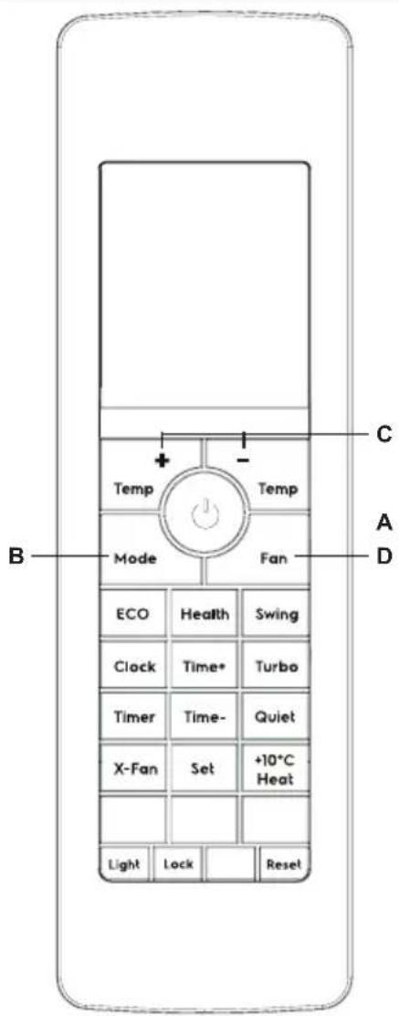
- Press the ON/OFF button (A) to start the air conditioner.
- Press the MODE button (B) to select Auto, Cool, Fan, Heat or Dry mode.
- Press the Temp+/- button (C) to set the desired temperature. The temperature can be set within a range of 16°C\~30°C in 1°C increments.
- Press the FAN SPEED button (D) to set the desired fan speed.
- Press the ON/OFF button (A) to turn the air conditioner off.

- In the Fan mode, Eco function can not be available.
- In the Fan mode, the temperature setting can not be available.
Swing Operation
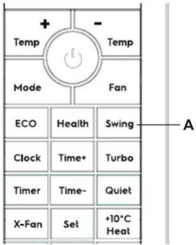
- When press the button (A), the air flow direction setting feature of the louver is activated. Press it again to stop.
- For models with Swing left/right function, short press button will activate up/down swing, and long 1 second press will activate left/right swing.

- When adjusting the flap by hand, turn off the unit.
- When humidity is high, condensate water might occur at air outlet if all vertical louvers are adjusted to left or right.
- It is advisable not to keep horizontal flap at downward position for a long time in COOL or DRY, otherwise, condensate water might occur.
- When restart after remote turning off, the remote controller will automatically memorize the previous set swing position.
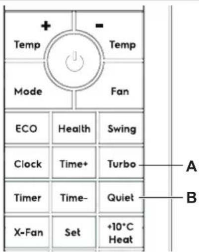
Turbo/Quiet Operation
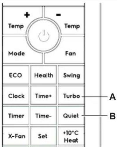
- Press the button (A) to enable or disable the turbo fuction. When enable the function, the symbol “→” will be shown.
When in turbo function, the fan will run in highest speed.
- Press the button (B) to enable or disable the quiet fuction. When enable the function, the symbol “” will be shown.
When in Quiet function, the fan will run in slowest speed.

- When you need fast cool, you can choose the Turbo function.
- when you sleeping or reading, you can choose Quiet function.
Timer Operation
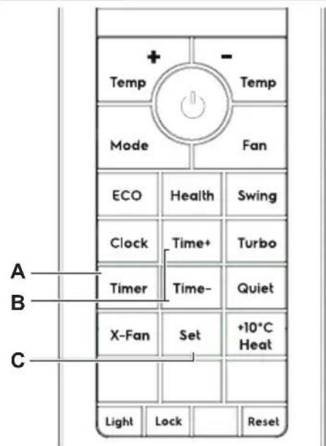
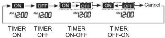
Press the Timer button (A) can set the auto-on and auto-off time of the unit. Every press the button can select timer mode as below sequence:
flowchart
graph LR
    A["ON"] --> B["OFF"]
    B --> C["ON"]
    C --> D["OFF"]
    D --> E["ON ← OFF"]
    E --> F["Cancel"]
    style A fill:#f9f,stroke:#333
    style B fill:#f9f,stroke:#333
    style C fill:#f9f,stroke:#333
    style D fill:#f9f,stroke:#333
    style E fill:#f9f,stroke:#333
    style F fill:#f9f,stroke:#333
To set the Timer On/Off time.
- Press the Timer button to select your desired timer mode (Timer On, Timer Off, Timer On-Off, Timer Off-On), the signal "ON" or "OFF" will flash on the display.
- Press the Time +/- button (B) to set the desired time you want to turn the unit on or off.
- Press the Set button (C) to confirm the setting.
To cancel the Timer setting.
After confirm the Timer setting, press Timer button several times until Timer mode disappears.

- The working time of the timer function set by the remote controller depends on the Clock time. Check that the Clock on the remote controller is set correctly in order to prevent malfunctioning.
- The effective operation time set by the remote controller is limited in 24 hours.
- Holding down the Time +/- to accelerate the process.
• After replacing batteries or a power failure happens, timer setting should be reset. - According to the Timer setting sequence of Timer On or Timer Off, either On-Off or Off-On can be achieved.
Setting the Clock
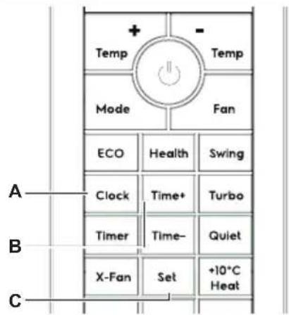
Before you start operating the air conditioner, set the clock of the remote controller using the procedure given in this section. The clock panel on the remote controller will display the time regardless of whether the air conditioner is in operation or not. After batteries are inserted in the remote controller or press the Reset button, "AM will display and begin to flash.
- Press the Clock button (A) to set the clock, and the symbol "A" or " " will flash.
- Press the Time +/- button (B) to set the desired time.
- Press the Set button (C) to confirm the setting and the symbol "A" or " " will stop flash.
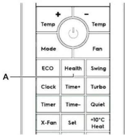
Health Operation
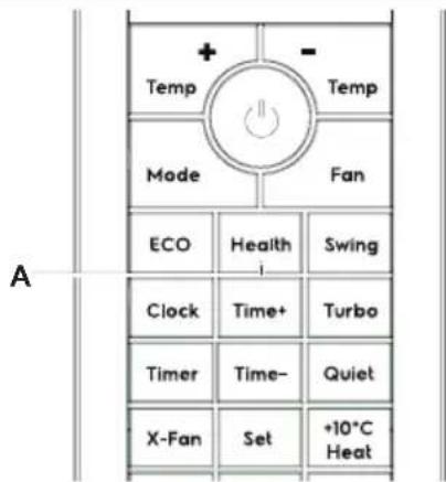
Press the Health button (A) to activate the Health function. The Cold Plasma generator releases plasma which can eliminate bacteria, viruses, dusts and other harmful agents in the air. This function is recommended when the indoor air quality is in bad condition.

- When indoor fan motor is running, it has healthy process function.
X-Fan Operation
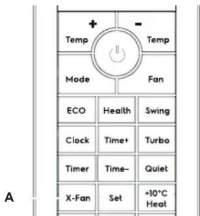
In Cool or Dry mode, press the X-Fan button (A) on the remote controller, indoor unit receives a signal from remote controller and have a sound and the panel flashes with "SC" for 3 seconds, and also flashes once every 0.5 seconds, then display is back to the previous status; After receiving the shutdown command, the indoor fan continues to blow for 2 minutes with "SC" display.
Eco Operation
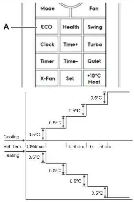
When you press the Eco button (A), the power saving function will be activated. The set temperature will increase(cooling) or decrease(heating) by 0.5°C per half a hour. The final temperature will then be maintained till further changes made by the user.

- The Eco function is only available under Cool, Heat and Dry mode.
- After setting the Eco function, press the "Turbo" or "Quiet" button to exit the power saving function.
- If the Eco function is set, you can not change the fan speed.
• After canceling the power saving function, the original temperature and fan speed setting will be restored.
+10°C Heat Operation
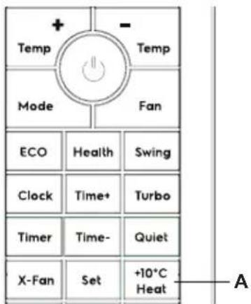
In Heat mode, press +10°C heat button (A) on the remote controller to activate the 10°C heat function, the temperature setting becomes 10°C.

- 10^ C Heat is only effective in heating mode.
- Switch mode and adjust the temperature setting, the 10°C heat function will stop working automatically.
Light/Wi-Fi Operation
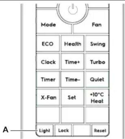
Press the Light button (A) once to show the ambient temperature.
Press the Light button twice in a row in 5 seconds the display extinguishes, and then the display lights when receiving a Light.
Continuous pressing Light button 7 times in 10s, then enter the Wi-Fi binding status

- Please refer to the "Quick Connection Guide" for the Wi-Fi connection details.
9. HOW TO USE THE INDOOR UNIT
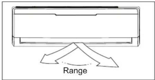

WARNING!
- Do not operate the air conditioner for long periods with the air flow direction set downward in cooling or dehumidifying mode. Otherwise, condensation may occur on the surface of the horizontal louver causing moisture to drop on to the floor or on furnishings.
- When the air conditioner is started immediately after it was stopped, the horizontal louver might not move for approximately 10 seconds. Louver in closed position.
- Adjust the air flow direction properly otherwise it might cause discomfort or cause uneven room temperatures.
- Adjust the horizontal louver using the remote controller.
- Adjust the vertical louver using the remote controller.
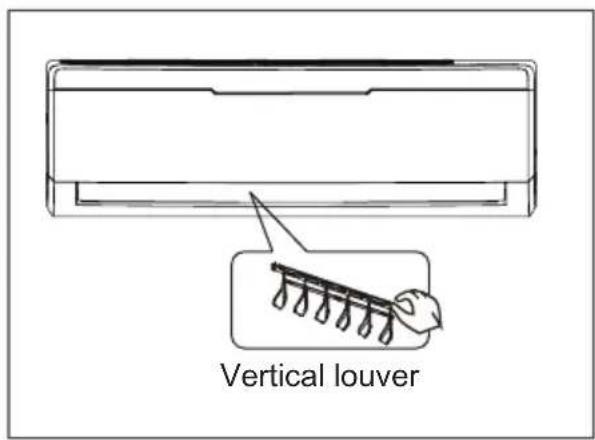
- Adjust the vertical louver manually (For models without 3D Swing function).
To set the vertical air flow (Up--Down) direction
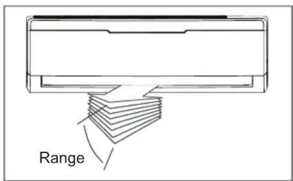
Perform this function while the unit is in operation. Use the remote controller to adjust the air flow direction. The horizontal louver can swing up and down automatically.
To set the horizontal air flow direction (left - right)
Perform this function while the unit is in operation. Use the remote controller to adjust the air flow direction. The vertical louver can swing left and right automatically.
For models without 3D Swing function, you need to move the vertical louver manually to adjust the air flow in the direction you prefer.
IMPORTANT!
Do not put your fingers into the panel of blower and suction side. The high-speed fan inside may cause danger.
- Open angle of the horizontal louver should not be set too small, as COOLING performance may be impaired due to too restricted air flow area.
- Do not move the horizontal louver manually, otherwise the horizontal louver will be out of sync. Please cease operating, unplug power for a few seconds, then restart the air conditioner.
- Do not operate unit with horizontal louver in closed position.
| Operating temperature ranges | ||
| Model climate Type | Ambient temperature (Cool) Ambient temperature (Heat) | |
| T1 18°C~43°C | -7°C~24°C | |
Important!
-
Optimum performance will be achieved within these operating temperatures. If air conditioner is used outside of the above conditions, certain safety protection features might come into operation and cause the unit to function abnormally.
-
If the air conditioner runs for a long time in cooling mode and the humidity is high, condensed water may drip out of the unit. Please sets the vertical air flow louver to its maximum angle (vertically to the floor), and set HIGH fan mode.
Use this operation only when the remote controller is defective or lost, and with function of emergency running, air conditioner can run automatically for a while.
- Open and lift the front panel up to an angle and fixed the position.
- When the emergency operation switch is pressed, the "Pi" sound is heard once, which means the start of this operation.
- When power switch is turning on for the first time and emergency operation starts, the unit will run automatically in the cool mode when room temperature above 23^ C and run in heat mode when room temperature below 23^ C.
- Close the panel firmly to its original position.

- It is impossible to change the settings of temp. and fan speed, It is also not possible to operate in time or dry mode.
- To restore the remote controller operation, use the remote controller directly.
To achieve optimal performance, please note the following:
- Adjust the air flow direction correctly.
- Adjust the temperature to achieve the highest comfort level. Do not adjust the unit to excessive temperature levels.
- Close doors and windows on COOL or HEAT modes, or performance may be reduced.
-
Use TIME ON button on the remote controller to select a time you want to start your air conditioner.
-
Do not put any object near air inlet or air outlet, as the efficiency of the air conditioner may be reduced and the air conditioner may stop running.
- Clean the air filter periodically, otherwise cooling or heating performance may be reduced.
- Do not operate unit with horizontal louver in closed position.
13. CLEANING AND MAINTENANCE
13.1 Before Mainatenance
Turn the system off before cleaning. To clean, wipe with a soft, dry cloth. Do not use bleach or abrasives.

WARNING!
Power supply must be disconnect before cleaning the indoor unit.

- A cloth dampened with cold water may be used on the indoor unit if it is very dirty. Then wipe it with a dry cloth.
- Do not use a chemically treated cloth or duster to clean the unit.
- Do not use benzine, thinner, polishing powder, or similar solvents for cleaning. These may cause the plastic surface to crack or deform.
- Never use water hotter than 40^ C/104°F to clean the front panel, it could cause deformation and discoloration.
13.2 Cleaning the Unit
Wipe the unit with a soft dry cloth only. If the unit is very dirty, wipe it with a cloth soaked in warm water.
13.3 Cleaning the Filters
A clogged air filter reduces the cooling efficiency of this unit. Please clean the filter once every 2 weeks.
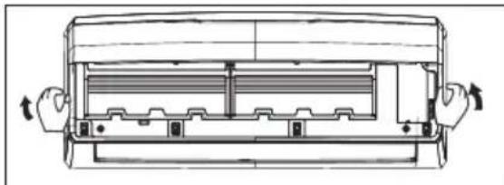
natural_image
Technical line drawing of a car air conditioner unit with hands operating the panel (no text or symbols)- Lift the indoor unit front panel up to an angle until it stops with a full support from the bracket.
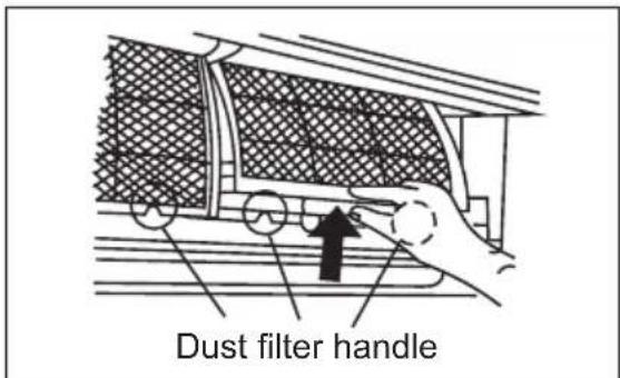
- Hold the dust filter handle and lift it up slightly to take it out from the filter holder.
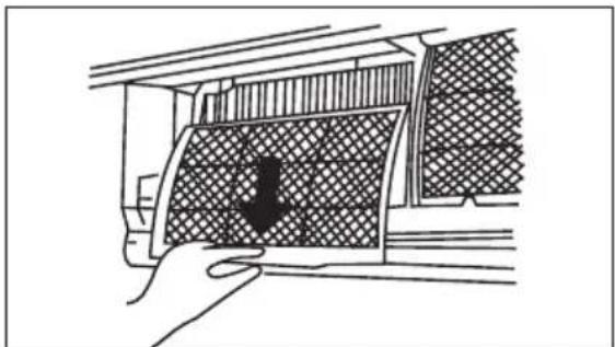
natural_image
Line drawing of a hand opening a window with a patterned panel (no text or symbols)- Then pull the dust filter downwards out of the indoor unit.
-
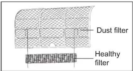
The healthy air freshening filter (if applicable) like Active carbon filter / Bio-Hepa filter / Vitamin C filter / 3M filter / Silver ion filter are fixed on the dust filte.
-
Remove the healthy filter from the support frame of the dust filter.
- Clean the healthy filter at least every 3 months and replace every 6 months.
- Clean with vacuum cleaner if possible.
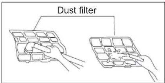
Clean the Dust filter with a vacuum cleaner or water, then dry it up in cool place.
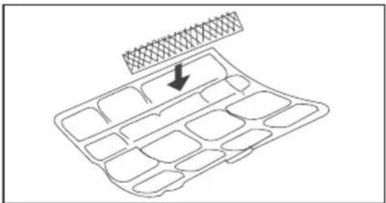
- Install the air freshening filter back into position.
natural_image
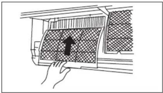
Diagram of a grid-like structure with an arrow pointing to a top panel (no text or symbols)- Insert the upper portion of air filter back into the unit, taking care that the left and right edges line up correctly and place filter into position.
natural_image
Diagram showing a hand pressing down on a car air vent with a grid-patterned panel and an upward arrow (no text or symbols)13.4 Cleaning the air outlet and the panel
- Use a dry and soft cloth to wipe it.
- Pure water or mild detergent may be used if it is very dirty.

WARNING!
- Do not use benzine, thinner, polishing powder, or similar solvents for cleaning. These may cause the surface to crack or deform.
• To avoid the risk of electrical shock or fire, do not let water fall into the indoor unit. - Never wipe the air flow louver violently.
- An air conditioner without air filter can not expel the dust out of the room, which would cause malfunctions by accumulation.
13.5 Replacement the filters
- Remove the air filter.
- Remove the air freshening filter.
- Install a new air freshening filter.
- Reinstall the air filter and securely close the front panel.
13.6 Preparation for extended non-operation
If you plan to idle the unit for a long time, perform the following:
- Clean the indoor unit and filters.
- Operate the fan for about half a day to dry the inside of the unit.
- Stop the air conditioner and disconnect power.
- Remove the batteries from the remote controller. The outdoor unit requires periodic maintenance and cleaning. Do not attempt to do this yourself. Contact your dealer or service provider.
13.7 Pre-season inspection
- Check that the wiring is not broken off or disconnected.
- Clean the indoor unit and filters.
- Check that the air filter is installed.
- Check if the air outlet or inlet is blocked after the air conditioner has not been used for a long time.

WARNING!
- Do not touch the metal parts of the unit when removing the filter. Injuries can occur when handling sharp metal edges.
- Do not use water to clean inside the air conditioner. Exposure to water can destroy the insulation, leading to possible electric shock.
- When cleaning the unit, first make sure that the power and circuit breaker are turned off.
- Do not wash air filter with hot water at more than 40^ C/104°F. Shake off moisture completely and dry it in the shade. Do not expose it directly to the sun, it may shrink.
14. OPERATION TIPS
The following events may occur during normal operation.
1. Protection of the air conditioner Compressor
- The compressor can't restart for 3-4 minutes after it stops.
Anti-cold air (Cooling and heating models only)
- The unit is designed not to blow cold air on HEAT mode, when the indoor heat exchanger is in one of the following three situations and the set temperature has not been reached.
A) When heating has just started.
B) Defrosting.
C) Low temperature heating.
- The indoor or outdoor fan stop running when defrosting (Cooling and heating models only).
Defrosting (Cooling and heating models only)
- Frost may be generated on the outdoor unit during heat cycle when outdoor temperature is low and humidity is high resulting in lower heating efficiency of the air conditioner.
- During this condition air conditioner will stop heating operation and start defrosting automatically.
- The time to defrost may vary from 4 to 10 minutes according to the outdoor temperature and the amount of frost built up on the outdoor unit.
2. A white mist coming out from the indoor unit
- A white mist may generate due to a large temperature difference between air inlet and air outlet on COOL mode in an indoor environment that has a high relative humidity.
- A white mist may generate due to moisture generated from defrosting process when the air conditioner restarts in HEAT mode operation after defrosting.
3. Abnormal noise of the air conditioner
- You may hear a low hissing sound when the compressor is running or has just stopped running. It is the sound of the refrigerant flowing or coming to a stop.
- You can also hear a low “squeak” sound when the compressor is running or has just stopped running. This is caused by heat expansion and cold contraction of the plastic parts in the unit when the temperature is changing.
- A noise may be heard due to louver restoring to its original position when power is turned on.
4. Dust is blown out from the indoor unit
This is a normal condition when the air conditioner has not been used for a long time or during first use of the unit.
5. A peculiar smell comes out from the indoor unit
This is caused by the indoor unit giving off smells permeated from building material, from furniture, or smoke.
6. The air conditioner turns to FAN only mode or stop operation from COOL or HEAT mode
When indoor temperature reaches the temperature setting on air conditioner, the compressor will stop automatically, and the air conditioner turns to FAN only mode or stop operation. The compressor will start again when the indoor temperature rises on COOL mode or falls on HEAT mode.
7. The air conditioner runs Anti-mildew function after turning off the unit.
- When turning off the unit under COOL and DRY mode, the air conditioner will run for 2 minutes to anti-mildew, then stop the operation and turn off the unit automatically.
- Dripping water may generate on the surface of the indoor unit when cooling in a high relatively humidity. Adjust the horizontal louver to the maximum
air outlet position and select HIGH fan speed.
8. Heating mode (For cooling and heating models only)
The air conditioner draws in heat from the outdoor unit and releases it via the indoor unit during heating operation. When the outdoor temperature falls, heat drawn in by the air conditioner decreases accordingly. At the same time, heat loading of the air conditioner increases due to larger difference between indoor and outdoor temperature. If a comfortable temperature can't be achieved by the air conditioner, we suggest you use a supplementary heating device.
9. Auto-restart function
- Power failure during operation will stop the unit completely.
- For the unit without Auto-restart feature, when the power restores, the OPERATION indicator on the indoor unit will flash for 1second. To restart the operation, push the ON/OFF button on the remote controller. For the unit with Auto-restart feature, when the power restores, the unit restarts automatically with all the previous settings preserved by the memory function.
15. TROUBLESHOOTING
| Trouble | OPERATION (RUN) indicator or other indicators continue flashing. | The unit may stop operation or continue to run in a safety condition(depending on models). Waiting for about 10 minutes, the fault may be recovered automatically, if not, disconnect the power and then connect it in again. If the problem still exists, disconnect the power and contact the nearest customer service center. |
| If one of the following code appears on the display area: E1, E2, E4...En, F1, F2, F3...Fn | ||
| Fuse blows frequently or circuit breaker trips frequently. | Stop the air conditioner immediately, disconnect the power and contact the nearest customer service center. | |
| Other objects or water fall into the air conditioner. | ||
| Terrible odors are smelled or abnormal sounds are heard. | ||
| SC code appears on the display area. | It is normal. The unit is in X-fan operation. |
| Malfunctions Cause What should be done? | ||
| Unit does not start | Power cut Wait for power to be restored. | |
| Unit may have become Unplugged. | Check that plug is securely in wall receptacle. | |
| Fuse may have blown. Replace the fuse. | ||
| Battery in Remote controller may have been exhausted. | Replace the battery. | |
| The time you have set with timer is incorrect. | Wait or cancel timer setting. | |
| Unit not cooling or heating (Cooling/heating models only) room very well while air flowing out from the air conditioner | Inappropriate temperature setting. | Set temperature correctly. For detailed method please refer to “Using remote controller” section. |
| Air filter is blocked. Clean the air filter. | ||
| Doors or Windows are open. Close the doors or windows. | ||
| Air inlet or outlet of indoor or outdoor unit has been blocked. | Clear obstructions away first, then restart the unit. | |
| Compressor 3 minutes protection has been activated. | Wait | |
| If the trouble has not been corrected, please contact a local dealer or the nearest customer service center. Be sure to inform them of the detailed malfunctions and unit model number. Do not attempt to repair the unit yourself. Always consult an authorized service provider. | ||
16. CORRECT DISPOSAL OF THIS PRODUCT

This marking indicates that this product should not be disposed with other household wastes throughout the EU. To prevent possible harm to the environment or human health from uncontrolled waste disposal, recycle it
responsibly to promote the sustainable reuse of material resources. To return your used device, please use the return and collection systems or contact the retailer where the product was purchased. They can take this product for environmental safe recycling.
INNHOLD
- SIKKERHETSANVISNINGER....25
- PRODUKTBESKRIVELSE 27
- VISNING FOR INNEND∅RSENHET 28
- FJERNKONTROLLER 28
- BESKRIVELSE AV FJERNKONTROLL....30
- DISPLAYINDIKATOR FOR FJERNKONTROLL 32
- F∅RSTE BRUK....33
- SLIK BRUKER DU FJERNKONTROLLEN 33
- SLIK BRUKER DU INNEND∅RS ENHET....38
- DRIFTSTEMPERATUR....39
- N∅DBRUK 39
- OPTIMAL DRIFT ....40
- RENGJ∅RING OG VEDLIKEHOLD....40
- BRUKSTIPS 43
- PROBLEML∅SING 44
- KORREKT AVHENDING AV DETTE PRODUKTET 45
VI TENKER PÅ DEG
Takk for at du har kjøpt et produkt fra Electrolux. Du har valgt et produkt som bringer flere tiår med erfaring og innovasjon med seg. Genialt og stilig, produktet er designet med deg i tankene. Så uansett når du bruker det, kan du være trygg på at du får et godt resultat hver gang.
www.electrolux.com/productregistration

natural_image
Diagram of a battery moving through a slot with arrows indicating direction (no text or symbols)1 Temp +/- -knapp
2 Fan-knapp
3 Swing-knapp
4 Turbo-knapp
5 Quiet-knapp
6 +10°C Heat-knapp
7 Set-knapp
8 Reset-knapp
9 Lock-knapp
10 Light-knapp
11 X-Fan-knapp
12 Time +/- knapp
13 Timer-knapp
14 Clock-knapp
15 Health-knapp
16 Eco-knapp
17 Mode-knapp
18 On/Off-knapp
ON/OFF-KNAPP
Standardinnstilling: ON

Standardinnstilling: OFF.
6. DISPLAYINDIKATOR FOR FJERNKONTROLL
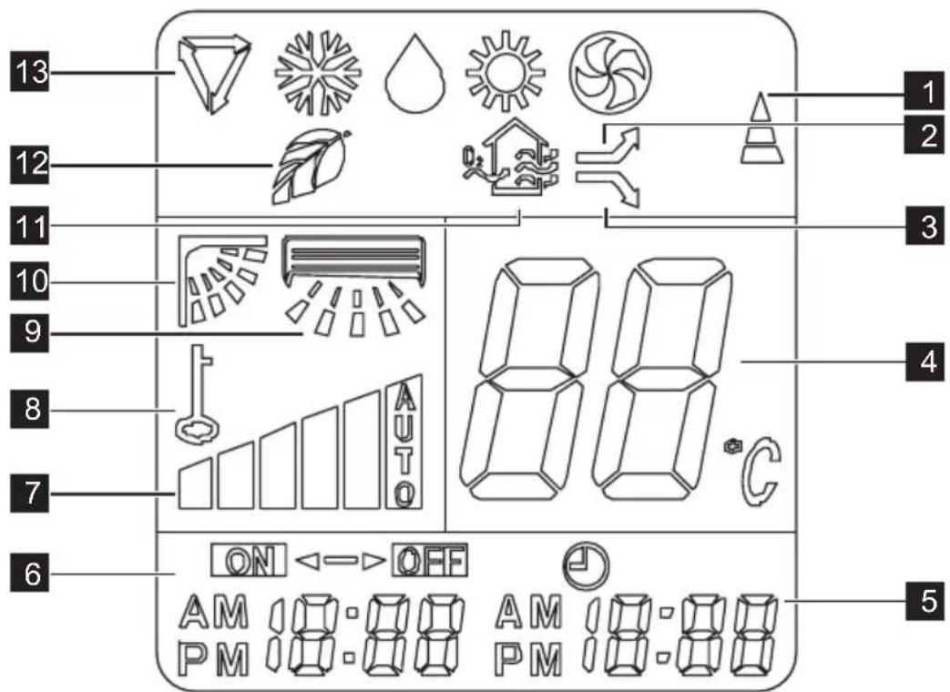
SWING UP/DOWN-SKJERM
Vises när Sving-funksjonen er aktivert.
SWING LEFT/RIGHT-SKJERM
Vises när Sving-funksjonen er aktivert.
LOCK-SKJERM
Vises när Lås-funksjonen er aktivert.
FAN-SKJERM
For å stille Timer On/Off.
natural_image
Technical line drawing of a mechanical component with arrows indicating assembly or movement (no text or symbols)natural_image
Line drawing of a hand opening a window with a patterned screen (no text or symbols)natural_image
Diagram of a grid-like structure with an arrow pointing to a textured top layer (no text or symbols)natural_image
Diagram showing a hand pressing down an air vent with a grid-patterned panel and an upward arrow (no text or symbols)natural_image
Diagram of a battery moving in a row with arrows indicating direction (no text or symbols)1 Temp +/- knap
2 Blæser-knap
3 Sving-knap
4 Turbo-knap
5 Stille-knap
6 +10°C varmeknap
7 Indstil-knap
8 Nulstil-knap
9 Lås-knap
10 Lyskontakt
11 X-blæser
12 Tid +/- knap
13 Timerknap
14 Urknap
15 Sundhedsknap
16 Eco-knappen
17 Funktionsvælger
18 Tænd-/sluk-knap
TIL-/FRA-KNAP
Slå displayet til ved at trykke på en vilkårlig knap.
TILSTAND-KNAP
flowchart
graph LR
    A["LAV (LOW)"] --> B["MEL (MED)"]
    B --> C["HØJ (HI)"]
    C --> D["AUTO"]
Turbo/Quiet Operation
Health Operation (Helbredsbetjening)
Tryk på knappen (A) en gang for at få vist temperaturen i omgivelserne.
natural_image
Technical line drawing of a front panel with arrows indicating directional movement (no text or symbols)natural_image
Line drawing of a hand opening a car window with a patterned vent (no text or symbols)natural_image
Hand placing a grid-patterned air vent into a car (no text or symbols visible)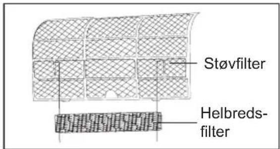
natural_image
Diagram of a grid-like structure with an arrow pointing to a textured top layer (no text or symbols)INNEHÅLLSFÖRTECKNING
- SÄKERHETSINSTRUKTIONER 69
- PRODUKTBESKRIVNING 71
- INOMHUSENHETENS DISPLAY....72
- FJÄRRKONTROLL 72
- BESKRIVNING AV FJÄRRKONTROLL....74
- FJÄRRKONTROLLENS DISPLAYINDIKATOR 76
- NÄR PRODUKTEN ANVÄNDS FÖRSTA GÅNGEN....77
- SÅ HÄR ANVÄNDER DU FJÄRRKONTROLLEN....77
- SÅ HÄR ANVÄNDER DU INOMHUSENHETEN....82
- DRIFTSTEMPERATUR....83
- NÖDSITUATIONSDRIFT 83
- OPTIMAL ANVÄNDNING....84
- RENGÖRING OCH UNDERHÅLL 84
- ANVÄNDNINGSTIPS 87
- FELSÖKNING 88
- KORREKT KASSERING AV PRODUKTEN....89
VI TÄNKER PÅ DIG
natural_image
Diagram of a battery moving in a row with arrows indicating direction (no text or symbols)flowchart
graph LR
    A --> B
    B --> C
    C --> D
    D --> E
    E --> F
    F --> G
    G --> H
    H --> I
    I --> J
    J --> K
    K --> L
    L --> M
    M --> N
    N --> O
    O --> P
    P --> Q
    Q --> R
    R --> S
    S --> T
    T --> U
    U --> V
    V --> W
    W --> X
    X --> Y
    Y --> Z
    Z --> A
MDLHG H
natural_image
Technical line drawing of a mechanical device with hands operating it, showing internal components and directional arrows (no text or symbols)natural_image
Line drawing of a hand opening a window with a patterned screen (no text or symbols)natural_image
Diagram of a grid-like structure with an arrow pointing to a textured top layer (no text or symbols)natural_image
Diagram showing a hand pressing down an air vent with a grid-patterned panel and an upward arrow (no text or symbols)natural_image
Diagram of a battery moving in a row with arrows indicating direction (no text or symbols)1 Temp +/- -painike
2 Fan-painike
3 Swing-painike
4 Turbo-painike
5 Quiet-painike
6 +10°C Heat -painike
7 Set-painike
8 Reset-painike
9 Lock-painike
10 Valopainike
11 X-Fan-painike
12 Time +/- -painike
13 Timer-painike
14 Clock-painike
15 Health-painike
16 Eco-painike
17 Mode-painike
18 On/Off-painike
ON/OFF-PAINIKE
natural_image
Technical line drawing of a mechanical component with hands operating, showing internal structure and rotation arrows (no text or symbols)natural_image
Line drawing of a hand opening a car window with a patterned vent (no text or symbols)natural_image
Diagram of a grid-like structure with an arrow pointing to a textured top layer (no text or symbols)natural_image
Diagram showing a hand pressing down on a car air vent with a grid-patterned panel and an upward arrow (no text or symbols)natural_image
Repeating pattern of gray geometric shapes on white background, no text or symbols present- WE'RE THINKING OF YOU
- Visit our website to:
- CUSTOMER CARE AND SERVICE
- ⚠️ SAFETY INSTRUCTIONS
- Children and vulnerable people safety
- WARNING!
- Installation and Use
- R32 refrigerant warning
- PRODUCT DESCRIPTION
- INDOOR UNIT DISPLAY
- TEMPERATURE indication lamp
- Signal receiver
- Wi-Fi mode lamp
- Operation mode lamp
- REMOTE CONTROLLER
- How to use the Remote controller
- Location of the Remote Controller
- Battery installation/replacement
- REMOTE CONTROLLER DESCRIPTION
- ON/OFF BUTTON
- MODE BUTTON
- ECO BUTTON
- HEALTH BUTTON
- CLOCK BUTTON
- TIMER BUTTON
- TIME +/- BUTTON
- X-FAN BUTTON
- LIGHT BUTTON
- TEMP +/- BUTTON
- FAN BUTTON
- SWING BUTTON
- TURBO BUTTON
- QUIET BUTTON
- +10°C HEAT BUTTON
- SET BUTTON
- RESET BUTTON
- LOCK BUTTON
- REMOTE CONTROLLER DISPLAY INDICATOR
- MODE DISPLAY
- ECO DISPLAY
- HEALTH DISPLAY
- SWING UP/DOWN DISPLAY
- SWING LEFT/RIGHT DISPLAY
- LOCK DISPLAY
- FAN DISPLAY
- TIMER DISPLAY
- TRANSMISSION INDICATOR
- TURBO DISPLAY
- QUIET DISPLAY
- TEMP DISPLAY
- CLOCK DISPLAY
- FIRST USE
- HOW TO USE THE REMOTE CONTROLLER
- Swing Operation
- Turbo/Quiet Operation
- Timer Operation
- To set the Timer On/Off time.
- To cancel the Timer setting.
- Setting the Clock
- Health Operation
- X-Fan Operation
- Eco Operation
- +10°C Heat Operation
- Light/Wi-Fi Operation
- HOW TO USE THE INDOOR UNIT
- To set the vertical air flow (Up--Down) direction
- To set the horizontal air flow direction (left - right)
- IMPORTANT!
- CLEANING AND MAINTENANCE
- Before Mainatenance
- Cleaning the Unit
- Cleaning the Filters
- Cleaning the air outlet and the panel
- Replacement the filters
- Preparation for extended non-operation
- Pre-season inspection
- OPERATION TIPS
- Protection of the air conditioner Compressor
- Anti-cold air (Cooling and heating models only)
- Defrosting (Cooling and heating models only)
- A white mist coming out from the indoor unit
- Abnormal noise of the air conditioner
- Dust is blown out from the indoor unit
- A peculiar smell comes out from the indoor unit
- The air conditioner turns to FAN only mode or stop operation from COOL or HEAT mode
- The air conditioner runs Anti-mildew function after turning off the unit.
- Heating mode (For cooling and heating models only)
- Auto-restart function
- TROUBLESHOOTING
- CORRECT DISPOSAL OF THIS PRODUCT
- INNHOLD
- VI TENKER PÅ DEG
- ON/OFF-KNAPP
- DISPLAYINDIKATOR FOR FJERNKONTROLL
- SWING UP/DOWN-SKJERM
- SWING LEFT/RIGHT-SKJERM
- LOCK-SKJERM
- FAN-SKJERM
- For å stille Timer On/Off.
- TIL-/FRA-KNAP
- TILSTAND-KNAP
- Health Operation (Helbredsbetjening)
- INNEHÅLLSFÖRTECKNING
- VI TÄNKER PÅ DIG
- ON/OFF-PAINIKE
Brand : ELECTROLUX
Model : EPN12C58HWI
Category : Heat pump